

Page 1
SERVICE MANUAL
COLOUR TELEVISION
YA00820039
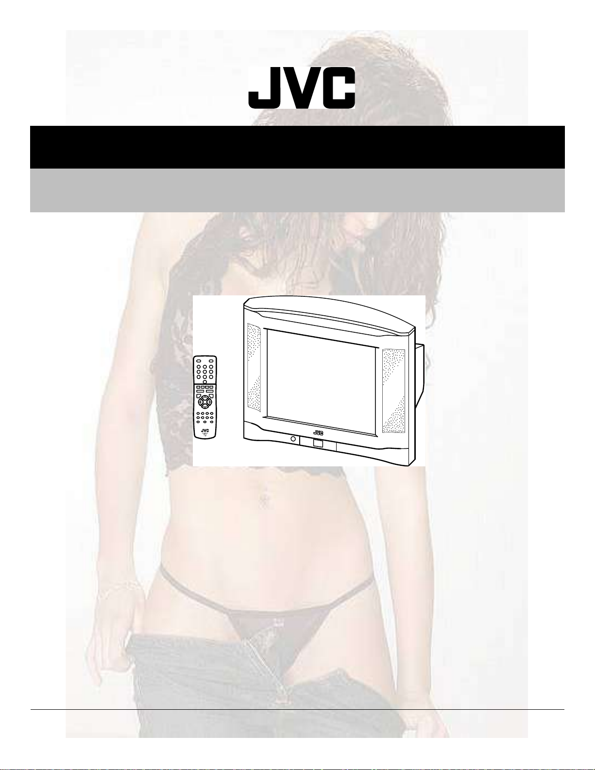
AV-29FH1BUG,
AV-29FH1SUG
TABLE OF CONTENTS
1PRECAUTION. . . . . . . . . . . . . . . . . . . . . . . . . . . . . . . . . . . . . . . . . . . . . . . . . . . . . . . . . . . . . . . . . . . . . . . . . 1-3
2SPECIFIC SERVICE INSTRUCTIONS. . . . . . . . . . . . . . . . . . . . . . . . . . . . . . . . . . . . . . . . . . . . . . . . . . . . . . 1-4
3DISASSEMBLY . . . . . . . . . . . . . . . . . . . . . . . . . . . . . . . . . . . . . . . . . . . . . . . . . . . . . . . . . . . . . . . . . . . . . . . 1-5
4ADJUSTMENT . . . . . . . . . . . . . . . . . . . . . . . . . . . . . . . . . . . . . . . . . . . . . . . . . . . . . . . . . . . . . . . . . . . . . . . . 1-8
5TROUBLESHOOTING . . . . . . . . . . . . . . . . . . . . . . . . . . . . . . . . . . . . . . . . . . . . . . . . . . . . . . . . . . . . . . . . . 1-12
COPYRIGHT © 2003 VICTOR COMPANY OF JAPAN, LIMITED
No.YA008
2003/9
Page 2

SPECIFICATION
Items
Dimensions ( W I H I D )81.2cm I 60.1cm I 52.2cm
Mass40kg
TV RF SystemCCIR (B/G, D/K, I , L/L')
Colour SystemPAL / SECAM / NTSC (Only in EXT mode)
Stereo SystemA2 (B/G, D/K) / NICAM (B/G, I, D/K, L)
Teletext SystemFastext (UK system)
TOP (German system)
WST(World standard system)
Receiving
Frequency
Intermediate
Frequency
Colour Sub
Carrier Frequency
Power InputAC220V ~ AC240V, 50Hz
Power Consumption84W, standby : 3W
Aerial Input Terminal75 unbalanced, coaxial
Picture TubeVisible size : 68cm (Measured diagonally)
Audio Power Output7W + 7W
EXT-1 / EXT-2 (Input / Output) 21-pin Euro connector (SCART socket I 2)
EXT-3 (Input) Video1V(p-p) 75 (RCA pin jack I 1)
Headphone JackStereo mini jack (Ø3.5mm) I 1
Remote Control UnitRM-C1514B (AAA/R03 dry battery I 2)RM-C1514 (AAA/R03 dry battery I 2)
Design & specifications are subject to change without notice.
VHF47MHz ~ 470MHz
UHF470MHz ~ 862MHz
French CATV116MHz ~ 172MHz / 220MHz ~ 469MHz
VIF Carrier38.9MHz (B/G, D/K, I , L) / 33.95MHz (L')
SIF Carrier33.4MHz (5.5MHz:B/G)
/ 32.9MHz (6.0MHz:I)
/ 32.4MHz (6.5MHz:L, D/K)
/ 40.45MHz (6.5MHz:L')
PAL4.43MHz
SECAM4.40625MHz / 4.25MHz
NTSC3.58MHz / 4.43MHz
Audio (L/R)500mV(rms) (-4dBs), High impedance (RCA pin jack I 2)
AV-29FH1BUGAV-29FH1SUG
Contents
1-2 (No.YA008)
Page 3

SECTION 1
PRECAUTION
1.1SAFETY PRECAUTIONS
(1)The design of this product contains special hardware,
many circuits and components specially for safety
purposes. For continued protection, no changes should be
made to the original design unless authorized in writing by
the manufacturer. Replacement parts must be identical to
those used in the original circuits. Service should be
performed by qualified personnel only.
(2)Alterations of the design or circuitry of the products should
not be made. Any design alterations or additions will void
the manufacturer's warranty and will further relieve the
manufacturer of responsibility for personal injury or
property damage resulting therefrom.
(3)Many electrical and mechanical parts in the products have
special safety-related characteristics. These
characteristics are often not evident from visual inspection
nor can the protection afforded by them necessarily be
obtained by using replacement components rated for
higher voltage, wattage, etc. Replacement parts which
have these special safety characteristics are identified in
the parts list of Service manual. Electrical components
having such features are identified by shading on the
schematics and by ( ) on the parts list in Service
manual. The use of a substitute replacement which does
not have the same safety characteristics as the
recommended replacement part shown in the parts list of
Service manual may cause shock, fire, or other hazards.
(4) Don't short between the LIVE side ground and
ISOLATED (NEUTRAL) side ground or EARTH side
ground when repairing.
Some model's power circuit is partly different in the GND.
The difference of the GND is shown by the LIVE : ( ) side
GND, the ISOLATED (NEUTRAL) : ( ) side GND and
EARTH : ( ) side GND.
Don't short between the LIVE side GND and ISOLATED
(NEUTRAL) side GND or EARTH side GND and never
measure the LIVE side GND and ISOLATED (NEUTRAL)
side GND or EARTH side GND at the same time with a
measuring apparatus (oscilloscope etc.). If above note will
not be kept, a fuse or any parts will be broken.
(5)If any repair has been made to the chassis, it is
recommended that the B1 setting should be checked or
adjusted (See B1 POWER SUPPLY check).
(6)The high voltage applied to the picture tube must conform
with that specified in Service manual. Excessive high
voltage can cause an increase in X-Ray emission, arcing
and possible component damage, therefore operation
under excessive high voltage conditions should be kept to
a minimum, or should be prevented. If severe arcing
occurs, remove the AC power immediately and determine
the cause by visual inspection (incorrect installation,
cracked or melted high voltage harness, poor soldering,
etc.). To maintain the proper minimum level of soft X-Ray
emission, components in the high voltage circuitry
including the picture tube must be the exact replacements
or alternatives approved by the manufacturer of the
complete product.
(7)Do not check high voltage by drawing an arc. Use a high
voltage meter or a high voltage probe with a VTVM.
Discharge the picture tube before attempting meter
connection, by connecting a clip lead to the ground frame
and connecting the other end of the lead through a 10k
2W resistor to the anode button.
(8)When service is required, observe the original lead dress.
Extra precaution should be given to assure correct lead
dress in the high voltage circuit area. Where a short circuit
has occurred, those components that indicate evidence of
overheating should be replaced. Always use the
manufacturer's replacement components.
(9) Isolation Check (Safety for Electrical Shock Hazard)
After re-assembling the product, always perform an
isolation check on the exposed metal parts of the cabinet
(antenna terminals, video/audio input and output terminals,
Control knobs, metal cabinet, screw heads, earphone jack,
control shafts, etc.) to be sure the product is safe to operate
without danger of electrical shock.
a) Dielectric Strength Test
The isolation between the AC primary circuit and all metal
parts exposed to the user, particularly any exposed metal
part having a return path to the chassis should withstand a
voltage of 3000V AC (r.m.s.) for a period of one second. (.
. . . Withstand a voltage of 1100V AC (r.m.s.) to an
appliance rated up to 120V, and 3000V AC (r.m.s.) to an
appliance rated 200V or more, for a period of one second.)
This method of test requires a test equipment not generally
found in the service trade.
b) Leakage Current Check
Plug the AC line cord directly into the AC outlet (do not use
a line isolation transformer during this check.). Using a
"Leakage Current Tester", measure the leakage current
from each exposed metal part of the cabinet, particularly
any exposed metal part having a return path to the chassis,
to a known good earth ground (water pipe, etc.). Any
leakage current must not exceed 0.5mA AC (r.m.s.).
However, in tropical area, this must not exceed 0.2mA AC
(r.m.s.).
Alternate Check Method
Plug the AC line cord directly into the AC outlet (do not
use a line isolation transformer during this check.). Use
an AC voltmeter having 1000 per volt or more
sensitivity in the following manner. Connect a 1500
10W resistor paralleled by a 0.15kF AC-type capacitor
between an exposed metal part and a known good earth
ground (water pipe, etc.). Measure the AC voltage
across the resistor with the AC voltmeter. Move the
resistor connection to each exposed metal part,
particularly any exposed metal part having a return path
to the chassis, and measure the AC voltage across the
resistor. Now, reverse the plug in the AC outlet and
repeat each measurement. Any voltage measured must
not exceed 0.75V AC (r.m.s.). This corresponds to
0.5mA AC (r.m.s.).
However, in tropical area, this must not exceed 0.3V AC
(r.m.s.). This corresponds to 0.2mA AC (r.m.s.).
AC VOLTMETER
(HAVING 1000/V,
OR MORE SENSITIVITY)
0.15F AC-TYPE
PLACE THIS PROBE
1500 10W
GOOD EARTH GROUND
ON EACH EXPOSED
METAL PART
(No.YA008)1-3
Page 4
SECTION 2
SPECIFIC SERVICE INSTRUCTIONS
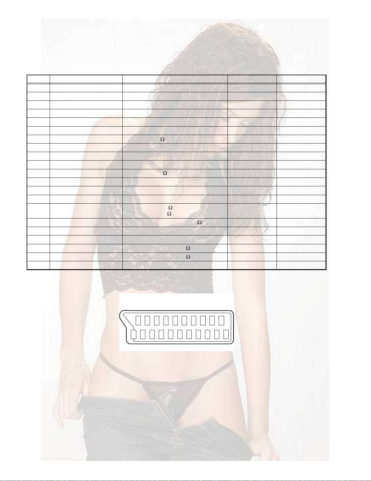
2.121-pin Euro connector (SCART) : EXT-1/EXT-2
Pin No.Signal designationMatching valueEXT-1EXT-2
1AUDIO R output500mV(rms) (Nominal), Low impedanceUsed (TV OUT)Used (LINE OUT)
2AUDIO R input500mV(rms) (Nominal), High impedanceUsed (R1)Used (R2)
3AUDIO L output500mV(rms) (Nominal), Low impedanceUsed (TV OUT)Used (LINE OUT)
4AUDIO GND---UsedUsed
5GND (B)---UsedUsed
6AUDIO L input500mV(rms) (Nominal), High impedanceUsed (L1)Used (L2)
7B input700mV
8FUNCTION SW (SLOW SW)Low : 0V-3V, High : 8V-12V, High impedanceUsedNC
9GND (G)---UsedNC
10SCL / T-V LINK---Not used NC
11G input700mV(B-W), 75 UsedNC
12SDA---Not used NC
13GND (R)---UsedUsed
14GND (YS)---UsedUsed
15R / C inputR : 700mV
C : 300mV
16Ys input (FAST SW)Low : 0V-0.4V, High : 1V-3V, 75 UsedNC
17GND (VIDEO output)---UsedUsed
18GND (VIDEO input)---UsedUsed
19VIDEO output1V
20VIDEO / Y input1V
(P-P)
(P-P)
21COMMON GND---UsedUsed
(P-P= Peak to Peak, B-W= Blanking to white peak)
, 75 UsedNC
(B-W)
(B-W)
(P-P)
, 75
, 75
Used (R)Used (C)
(Negative sync), 75 Used (TV OUT)Used (LINE OUT)
(Negative sync), 75 UsedUsed
1-4 (No.YA008)
Åз² ¿--·¹²³»²¬Ã
орпипкпмпоприкмо
оппзпйплпнппзйлнп
Page 5
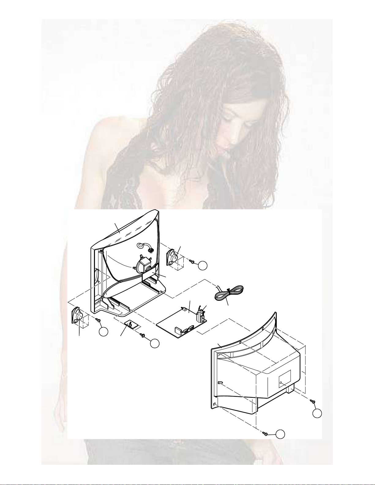
SECTION 3
DISASSEMBLY
3.1DISASSEMBLY PROCEDURE
3.1.1REMOVING THE REAR COVER
(1)Unplug the power cord.
(2)Remove the 8 screws [A].
(3)Remove the 1 screw [B].
(4)Withdraw the REAR COVER toward you.
3.1.2REMOVING THE SIDE SPEAKER
•Remove the REAR COVER.
(1)Remove the 4 screws [D], attaching the SPEAKER.
(2)Follow the same steps when removing the other hand
SPEAKER.
3.1.3REMOVING THE PFC FILTER PWB
•Remove the REAR COVER.
(1)Remove the 2 screws [C] as shown in the figure.
(2)Take off the 2 connectors linking chassis to PFC FILTER
PWB and withdraw the PFC FILTER PWB.
3.1.4REMOVING THE MAIN PWB
•Remove the REAR COVER.
(1)Slightly raise the both sides of the MAIN PWB by hand and
withdraw the MAIN PWB backward.
(If necessary, take off the wire clamp, connectors etc.)
FRONT CABINET
3.1.5CHECKING THE PW BOARD
•To check the back side of the PW Board.
(1)Pull out the MAIN PWB. (Refer to REMOVING THE MAIN
PWB).
(2)Erect the MAIN PWB vertically so that you can easily check
the back side of the PW Board.
3.1.6CAUTION
•When erecting the MAIN PWB, be careful so that there will be
no contacting with other PW Board.
•Before turning on power, make sure that the wire connector is
properly connected.
•When conducting a check with power supplied, be sure to confirm that the CRT EARTH WIRE (BRAIDED ASS'Y) is connected to the CRT SOCKET PW board.
3.1.7WIRE CLAMPING AND CABLE TYING
(1)Be sure to clamp the wire.
(2)Never remove the cable tie used for tying the wires
together.
Should it be inadvertently removed, be sure to tie the wires
with a new cable tie.
SPEAKER
D
PFC FILTER
PWB
C
SPEAKER
CRT SOCKET
PWB
MAIN PWB
D
FBT
POWER CORD
REAR COVER
B
A
(No.YA008)1-5
Page 6

3.2REPLACEMENT OF MEMORY IC
3.2.1MEMORY IC
This TV use memory IC. In the memory IC, there are memorized data for correctly operating the video and deflection circuits. When
replacing memory IC with a blanking memory IC, the set is automatically memorized following SERVICE MANU initial data.
3.2.2SERVICE MENU ADJUSTMENT ITEMS
There are 21 SERVICE ADJUSTMENT ITEMS. After replacing
memory IC, automatically memorized following initial data.
No.Adjustment item
1HOR CEN
2RED GAIN
3GRN GAIN
4BLUE GAIN
5RED BIAS
6GRN BIAS
7AGC LEVEL
8G2-SCREEN
9AFT
10OPTION1
11OPTION2
12AVL
13PARABOLA
14HOR WIDTH
15CORNER T
16CORNER B
17HOR PARAL
18V. LINEAR
19EW TRAPEZ
20S CORRECT
21VERT CENT
22VERT SIZE
23SHIPPING
3.2.3FACTORY SETTING
3.2.3.1FRONT BUTTON SETTING AND INITIAL SEETING
ItemValue
MAIN POWEROFF(SUB POWER ON)
PR POSITION01
INPUT MODETV
3.2.3.2USER MENU SETTING
ItemValue
PICTURE
BRIGHTNESSCenter
CONTRASTCenter
COLOURCenter
SHARPNESSCenter
TINTCenter
NOISE RED.WEAK
SOUND
VOLUME18
BALANCECenter
BASSCenter
TREBLECenter
FEATURES
CHILD LOCKOFF
WAKE TIMEOFF
WAKE PROG.01
CLOCK--:-CLOCK PROG01
PROG. INFOON
ZOOM AUTO4:3
LANGUAGEGB
INSTALL
ATSSOthers
EDIT
SYSTEMEURO
CHANNELC 02
FREQUENCY048. 25
NAME------PROGRAM01
STORE TO01
1-6 (No.YA008)
Page 7
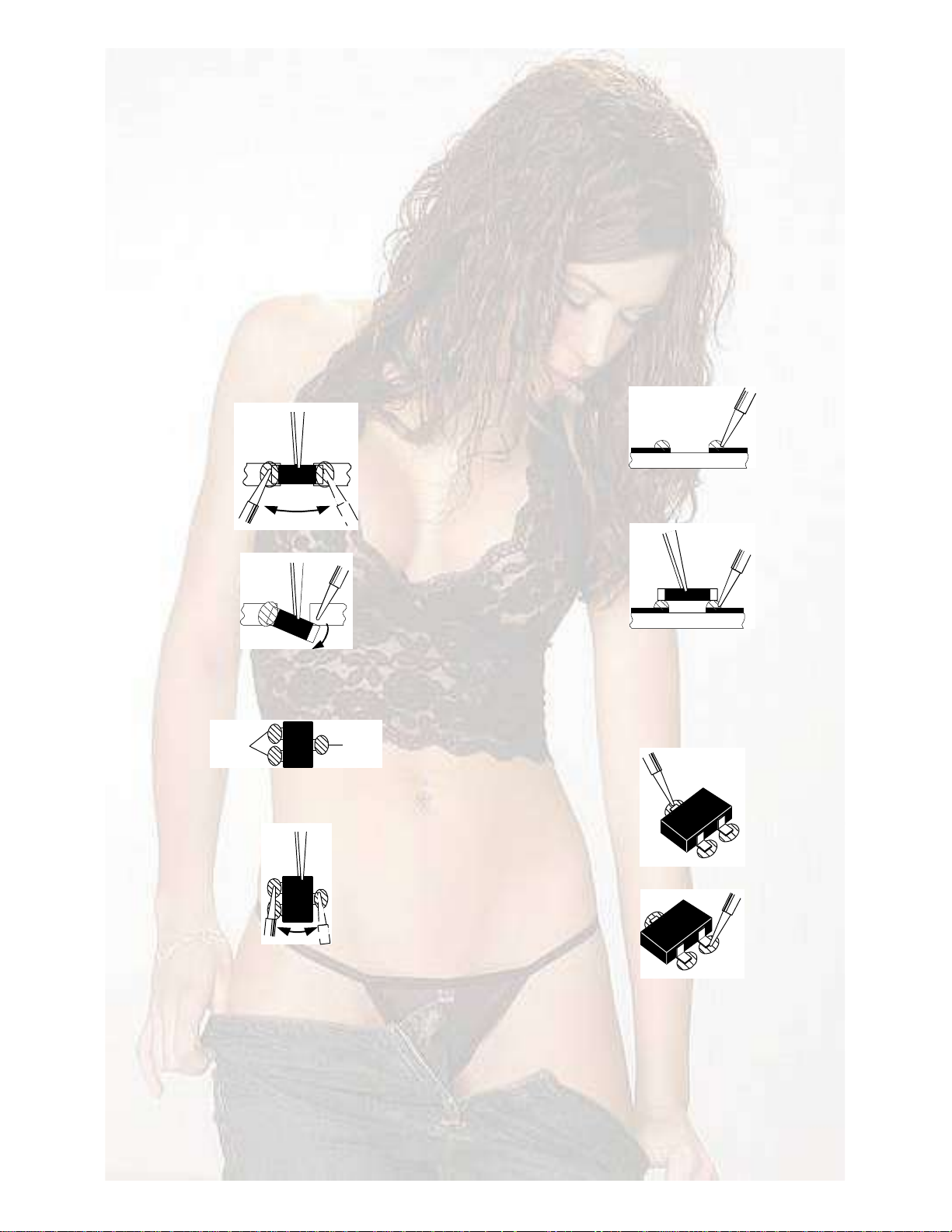
3.3REPLACEMENT OF CHIP COMPONENT
3.3.1CAUTIONS
(1)Avoid heating for more than 3 seconds.
(2)Do not rub the electrodes and the resist parts of the pattern.
(3)When removing a chip part, melt the solder adequately.
(4)Do not reuse a chip part after removing it.
3.3.2SOLDERING IRON
(1)Use a high insulation soldering iron with a thin pointed end of it.
(2)A 30w soldering iron is recommended for easily removing parts.
3.3.3REPLACEMENT STEPS
1. How to remove Chip parts
2. How to install Chip parts
[Resistors, capacitors, etc.]
(1)As shown in the figure, push the part with tweezers and
alternately melt the solder at each end.
(2)Shift with the tweezers and remove the chip part.
[Transistors, diodes, variable resistors, etc.]
(1)Apply extra solder to each lead.
НСФЬЫО
НСФЬЫО
(2)As shown in the figure, push the part with tweezers and
alternately melt the solder at each lead. Shift and remove
the chip part.
[Resistors, capacitors, etc.]
(1)Apply solder to the pattern as indicated in the figure.
(2)Grasp the chip part with tweezers and place it on the
solder. Then heat and melt the solder at both ends of the
chip part.
[Transistors, diodes, variable resistors, etc.]
(1)Apply solder to the pattern as indicated in the figure.
(2)Grasp the chip part with tweezers and place it on the
solder.
(3)First solder lead A as indicated in the figure.
ß
Þ
NOTE :
After removing the part, remove remaining solder from the
pattern.
(4)Then solder leads B and C.
Ý
ß
Þ
Ý
(No.YA008)1-7
Page 8
SECTION 4
ADJUSTMENT
4.1ADJUSTMENT PREPARATION
(1)There are 2 ways of adjusting this TV : One is with the REMOTE CONTROL UNIT and the other is the conventional method
using adjustment parts and components.
(2)Make sure that connection is correctly made AC to AC power source.
(3)Turn on the power of the TV and measuring instruments for warning up for at least 30 minutes before starting adjustments.
(4)If the receive or input signal is not specified, use the most appropriate signal for adjustment.
(5)Never touch the parts (such as variable resistors, transformers and condensers) not shown in the adjustment items of this service
adjustment.
4.2MEASURING INSTRUMENT AND FIXTURES
(1)DC voltmeter (or digital voltmeter)
(2)Signal generator (Pattern generator : PAL / SECAM / NTSC)
(3)Remote control unit.
4.3BASIC OPERATION OF SERVICE MENU
4.3.1TOOL OF SERVICE MENU OPERATION
Operate the SERVICE MENU with the REMOTE CONTROL UNIT.
4.3.2SERVICE ADJUSTMENT ITEMS
There are 23 adjustment items.
No.Adjustment itemNo.Adjustment item
1HOR CEN13PARABOLA
2RED GAIN14HOR WIDTH
3GRN GAIN15CORNER T
4BLUE GAIN16CORNER B
5RED BIAS17HOR PARAL
6GRN BIAS18V. LINEAR
7AGC LEVEL19EW TRAPEZ
8G2-SCREEN20S CORRECT
9AFT21VERT CENT
10OPTION122VERT SIZE
11OPTION223SHIPPING
12AVL
НЫОКЧЭЫ К»®рткй ж орсрлсрн
хррнкр
ÙÎÒ Ùß×Ò
Í»¬¬·²¹ ·¬»³
Í»¬¬·²¹ ª¿´«»
НЫОКЧЭЫ УЫТЛ НЭОЫЫТ
Ó«¬·²¹ µ»§
̱ Û²¬»®
ñ
øÍ»´»½¬ ·¬»³÷
ÓÛÒË
ø̱ »¨·¬÷
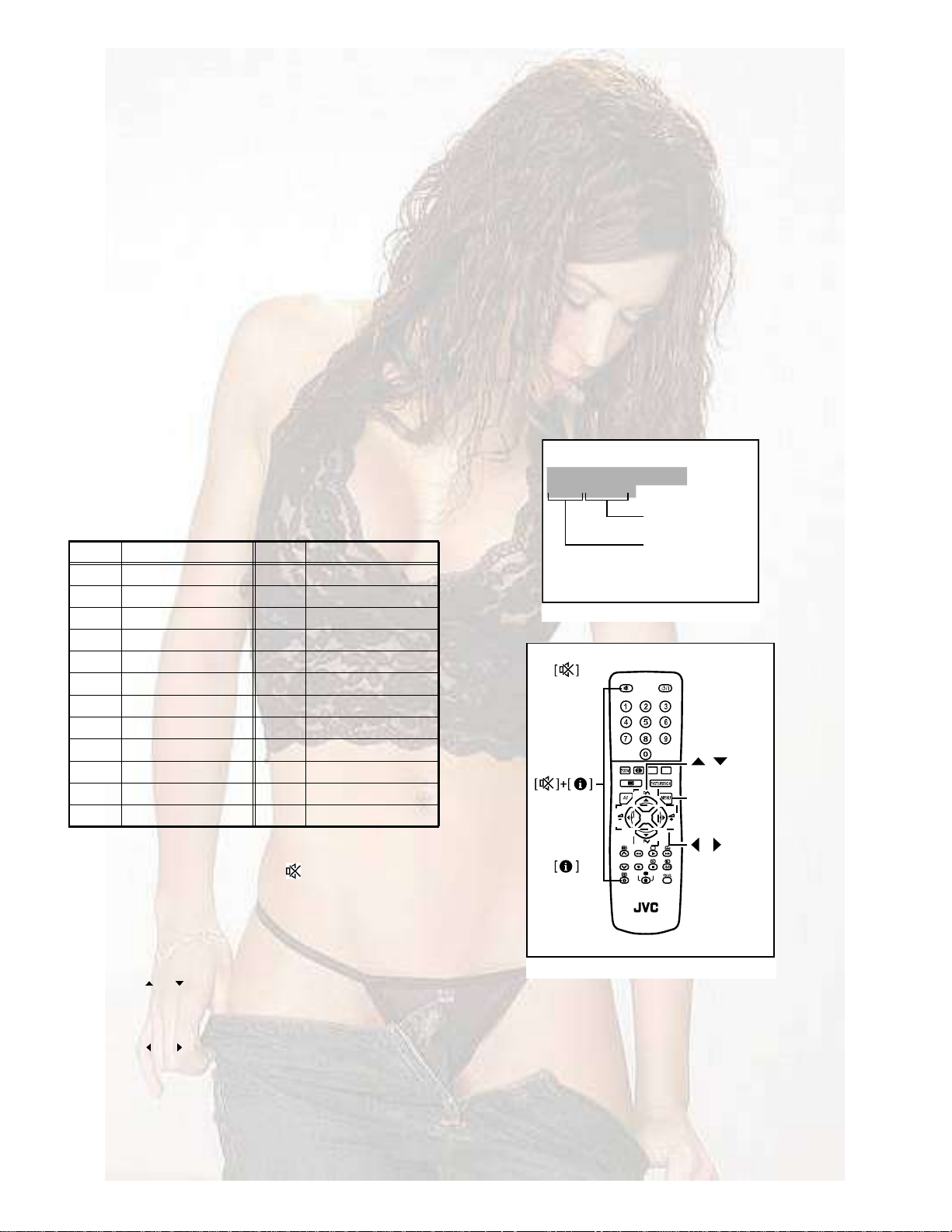
4.3.3HOW TO ENTER SERVICE MENU
(1)Press [ i ](Information) key and [ ](Muting) key same time
then enter SERVICE MENU.
(2)Adjust sharpness to minimum and exit all menus.
(3)Within 2 seconds press the key sequence [RED]-[GREEN]-
[MENU]key.
4.3.4SELECTION OF MENU SCREEN
(1)Press [ ] / [ ] keys of the REMOTE CONTROL UNIT and
select adjustment item.
4.3.5SETTING VALUE OF ADJUSTMENT ITEMS
(1)Press [ ] / [ ] keys of the REMOTE CONTROL UNIT and
setting value of adjustment items.
4.3.6HOW TO EXIT SERVICE MENU
(1)Press [MENU] key, then exit SERVICE MENU.
1-8 (No.YA008)
ײº±®³¿¬·±²
ÊÝÎ
µ»§
ОУуЭплпм
ÌÊ
ОЫУСМЫ ЭСТМОСФ ЛТЧМ
á
ÜÊÜ
ñ
øÍ»¬¬·²¹ ¼¿¬¿÷
Page 9
4.4ADJUSTMENT PROCEDURE
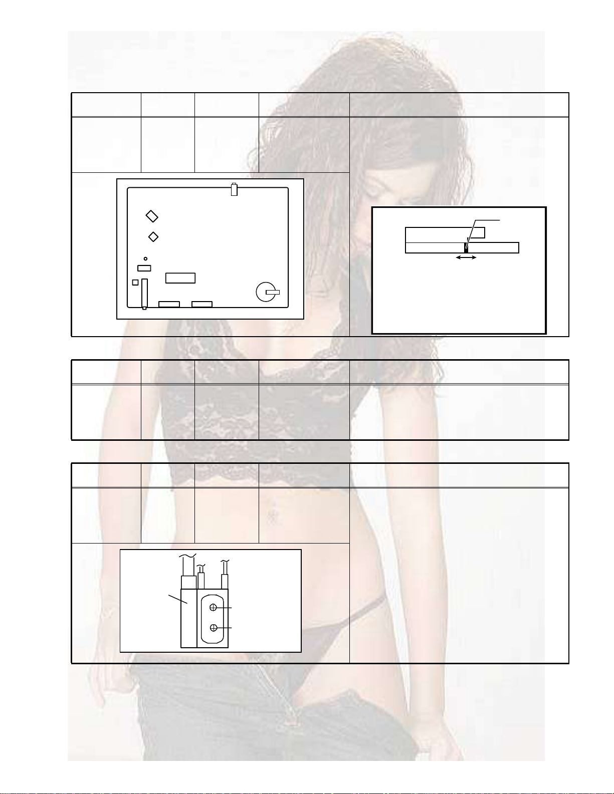
4.4.1LOCAL OSCILLATOR ADJUSTMENT
Item
AFT
adjustment
Measuring
instrument
Signal
generator
Test pointAdjustment partDescription
Remote
control unit
AFT
AFT coil : (L150)
[MAIN PWB]
(1)Receive a colour bar pattern signal.
(2)The frequency of the signal carrier must be accurate
(Max +/-10kHz deviation from the nominal channel
frequency).
(3)Select < AFT >.
(4)Adjust the AFT coil (L150) to bring the cursor to cen-
tral poison.
I502
I501
L150
I101
I702
I601
TUNER
4.4.2AGC
Item
AGC
adjustment
Measuring
instrument
Signal
generator
Remote
control unit
4.4.3FOCUS ADJUSTMENT
Item
FOCUS
adjustment
Measuring
instrument
Signal
generator
Remote
control unit
MAIN PWB
НЫОКЧЭЫ КСт нпЯ МРЛпз
хрррлй ЯЪМ ФЫКЫФ
FBT
Test pointAdjustment partDescription
AGC(1)Receive a colour bar pattern signal.
(2)Select < AGC >.
(3)Press the [OK] key and wait until AGC level stabilize
to the optimum value.
Test pointAdjustment partDescription
FOCUS VR
[On FBT]
(1)Receive a cross-hatch signal.
(2)Adjust the FOCUS volume on the FBT to have the
best resolution on the screen.
Ý«®-±®
FBT
FOCUS
SCREEN
(No.YA008)1-9
Page 10
4.4.4SCREEN ADJUSTMENT
Item
SCREEN
adjustment
4.4.5WHITE BALANCE ADJUSTMENT
Item
WHITE
BALANCE
adjustment
4.4.6DEFLECTION CIRCUIT ADJUSTMENT
Item
VERTICAL
GEOMETORY
adjustment
Measuring
instrument
Signal
generator
Remote
control unit
Measuring
instrument
Signal
generator
Remote
control unit
Measuring
instrument
Signal
generator
Remote
control unit
Test pointAdjustment partDescription
Test pointAdjustment partDescription
Test pointAdjustment partDescription
G2-SCREEN
SCREEN VR
[On FBT]
RED BIAS
GRN BIAS
RED GAIN
GRN GAIN
BLUE GAIN
V. LINEAR
S CORRECT
VERT SIZE
VERT CENT
(1)Receive a colour bar pattern signal.
(2)Select < G2-SCREEN >.
(3)Adjust the SCREEN VR on the FBT to bring the
cursor to central position.
(1)Receive a black and white pattern signal (colour off).
(2)Select < RED BIAS >, < GRN BIAS > and adjust the
screen until the black portion in the screen becomes
black.
(3)Select < RED GAIN >, < GRN GAIN >, < BLUE GAIN >
and adjust the screen until the white portion in the
screen become white.
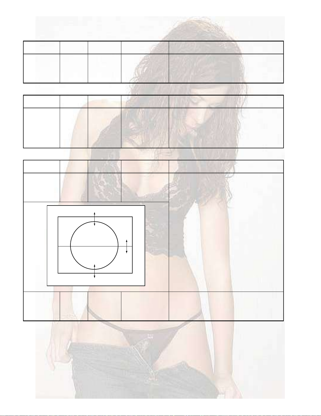
(1)Receive a circle pattern signal.
(2)Select < V. LINEAR >(Veretical linearity), < S
CORRECT > (S correction), < VERT SIZE >(Vertical
size), < VERT CENT >(Vertical center) respectively.
(3)Adjust to compensate for vertical distortion.
HORIZONTAL
POSITION
adjustment
1-10 (No.YA008)
Signal
generator
Remote
control unit
HOR CEN(1)Receive a circle pattern signal.
(2)Select < HOR CEN >(Horizontal center).
(3)Adjust to have the picture in the center of the screen.
Page 11
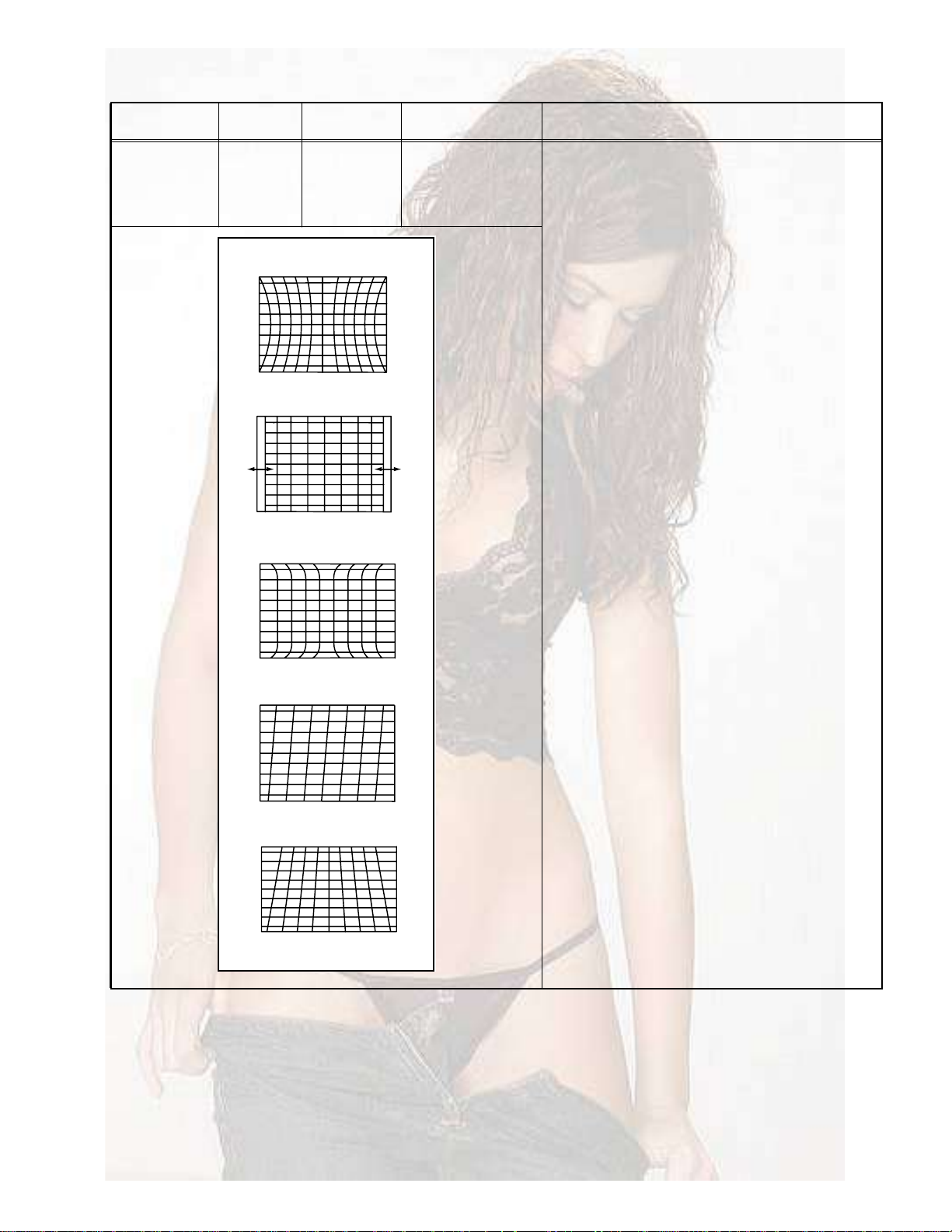
Item
HORIZONTAL
GEOMETORY
adjustment
Measuring
instrument
Signal
generator
Remote
control unit
Test pointAdjustment partDescription
PARABOLA
HOR WIDTH
CORNER
HOR PARAL
EW TRAPEZ
PARABOLA
HOR WIDTH
(1)Receive a cross-hatch pattern signal.
(2)Select < PALABOLA >(Side pin), < HOR WIDTH >
(Horizontal width), < CORNER >(Top/bottom
corner), < HOR PARAL >(Horizontal parallel), < EW
TRAPEZ >(Trapezium).
(3)Adjust these items to compensate for geometrical
distortion.
CORNER
HOR PARAL
EW TRAPEZ
(No.YA008)1-11
Page 12

SECTION 5
TROUBLESHOOTING
This service manual does not describe TROUBLESHOOTING.
1-12 (No.YA008)
Page 13

VICTOR COMPANY OF JAPAN, LIMITED
AV & MULTIMEDIA COMPANY VIDEO DISPLAY CATEGORY 12, 3-chome, Moriya-cho, kanagawa-ku, Yokohama, kanagawa-prefecture, 221-8528, Japan
(No.YA008)
Printed in Japan
WPC
Page 14

AV-29FH1SUG
AV-29FH1BUG
ENGLISH
DEUTSCH
FRANÇAIS
NEDERLANDS
CASTELLANO
ITALIANO
COLOUR TELEVISION
FARBFERNSEHGERÄT
TELEVISEUR COULEUR
KLEURENTELEVISIE
TELEVISOR A COLOR
TELEVISORE A COLORI
TELEVISOR A CORES
INSTRUCTIONS
BEDIENUNGSANLEITUNG
MANUEL D INSTRUCTIONS
GEBRUIKSAANWIJZING
MANUAL DE INSTRUCCIONES
ISTRUZIONI
INSTRUÇÕES
Page 15

Thank you for buying this JVC colour television.
To make sure you understand how to use your new TV, please read this manual thoroughly
before you begin.
WATER AND MOISTURE
1.
The apparatus shall not be exposed to dripping or splashing water and no object filled with liquids, such as vases , should
be placed on the apparatus.
HEAT
2.
Never place the set near heat sources.
Never put a naked flame, such as a candle, on the top of TV set.
VENTILATION
3.
Do not cover the ventilation openings in the cabinet and never place the set in a confined space such as in a bookcase or
built-in cabinet unless proper ventilation is provided. Leave a minimum 10 cm gap all around the unit.
OBJECT ENTRY
4.
Do not insert foreign objects, such as needles and coins, in the ventilation openings.
LIGHTNING STRIKE
5.
You should disconnect the set from the mains and the aerial system during thunderstorms.
CLEANING
6.
Unplug the set from the mains while cleaning.
AFTER MOVING THE SET
7.
If the set is moved or turned, the MAIN POWER button must be switched off for at least 15 minutes in order to take out
colour patches on the screen.
CAUTION
8.
There is danger of choking or suffocation if the cap which is removed from the TV is accidentally swallowed by children.
Store the cap out of the reach of children.
TV-LINK FUNCTION
1
2
3
3
4
7
8
12
14
15
16
Page 16

IDENTITY OF LOCAL & REMOTE CONTROL
LOCAL CONTROL
Front
B1
MAIN POWER button
B2
FRONT S-VIDEO INPUT socket Ext-3
B3
FRONT VIDEO INPUT socket Ext-3
B4
FRONT AUDIO INPUT socket Ext-3
B5
HEADPHONE socket
B1 B2 B3 B4 B5 B6 B7 B8 B9 B10
Rear
AERIAL socket
ßÒÌ
B6
STAND-BY indicator
B7
REMOTE sensor
B8
TV / AV button
B9
VOLUME UP/DOWN buttons
B10
PROGRAM UP/DOWN buttons
EN GLISH
SCART 1 socket EXT-1
SCART 2 socket EXT-2
REMOTE CONTROL
TV mode
ßï
ßî
ßí
ßì
ßë
ßê
ßé
ßè
ßç
ßïð
ßïï
ßïî
ßïí
ßïì
ßïë
ßïê
ßïé
ßïè
ßïç
ßîð
ßîï
ßîî
ßîí
ßîì
ßîë
ßîê
ð
РЧЭМЛОЫсСХ
V
2
SOUND MUTE
ñ×
POWER
9
NUMBER 0..9
¦±±³
ZOOM / SKIP
SOUND EFFECT / MOVE
SLEEP / DELETE
Not used
TV > TELETEXT
PICTURE / OK
ÓÛÒË
MENU
PROGRAM UP (CURSOR UP)
PROGRAM DOWN (CURSOR DOWN)
VOLUME DOWN (CURSOR LEFT)
VOLUME UP (CURSOR RIGHT)
ßÊ
TV / AV
Not used
Not used
Not used
Not used
Not used
Not used
Not used
Not used
i
INFORMATION
D
VCR / TELETEXT / DVD switch
I / II
MODE Stereo/Mono
Dual language
I / II
ЫИМуп
ßï
ßë
ï
ßì
ßè
ßïï
ßïë
ßïí
ßïé
ßïê
ßîð
ßîï
ßîì
ßîë
ЫИМуо
ø Í÷
ОУуЭплпм
РЧЭМЛОЫсСХ
ÓÛÒË
ОУуЭплпм
ßî
ßí
ßê
ßé
ßç
ßïð
ßïì
ßïî
ßïè
ßïç
ßîí
ßîî
ßîê
TELETEXT mode
ßï
ßî
ßí
ßì
ßë
ßê
ßé
ßè
ßç
ßïð
ßïï
ßïî
ßïí
ßïì
ßïë
ßïê
ßïé
ßïè
ßïç
ßîð
ßîï
ßîî
ßîí
ßîì
ßîë
ßîê
ð
SOUND MUTE
ñ×
POWER
9
NUMBER 0..9
RED
GREEN
YELLOW
CYAN
TELETEXT > TV
Not used
ÓÛÒË
VOL / BRIGHTNESS /CONTRAST
MENU
PAGE UP
PAGE DOWN
VOL / BRIGHTNESS / CONTRAST DOWN
VOL / BRIGHTNESS / CONTRAST UP
Not used
PAGE HOLD
Not used
?
REVEAL
DOUBLE SIZE
Not used
Not used
È
CANCEL
·
INDEX
SUBPAGE
VCR / TELETEXT / DVD switch
Not used
SELECTION
Page 17

SETTING UP
Batteries
EN GLISH
Open remote control battery compartment (at the
rear) and insert two 1.5V type AA / R6 batteries.
Warning: be careful to respect battery polarities.
START UP
SWITCHING ON
Switch the TV set on with the MAIN POWER button (B1).
LANGUAGE MENU
Insert the main plug into a
220 - 240V 50Hz AC
power socket.
Connect aerial to aerial jack.
It is usually connected by
means of a 75 ohm cable.
The very first time that you turn on the TV, the LANGUAGE menu will appear on the screen.
Its purpose is to enable you to select the language that will be used for all the OSD (On
Screen Display) menus. The user must enter a choice of language before proceeding further.
The descriptions used in the menu are those of the country code (e.g. GB = English, NL =
Holland etc).
P
PICTURE/OK
P
Selection is made by use of the remote control CURSOR UP (A11) / CURSOR DOWN (A12) buttons and CURSOR LEFT (A13) /
RIGHT (A14) buttons.Once you are satisfied with your selection, push the OK button (A9) to confirm your choice, and then the menu
willdisappear.
The language entered at this stage can still be modified at any later time, by entering the LANGUAGE selection (accessed from the
FEATURES menu page 11).
Note : The languages shown are subject to modification without prior notice.
3
3
Page 18

INSTALLATION
AUTO TUNING SYSTEM
MENU SELECTION
Press remote control MENU button (A10) to display the MAIN MENU.
Move the cursor to INSTALL by using the remote control CURSOR
UP (A11),DOWN(A12) buttons.
Then press the remote control OK button (A9).
Note: All menus are removed within 60 seconds if you don't press
any button.
COUNTRY SELECTION
Position the cursor at ATSS Menu and select country code where TV is
used by pressing the remote control CURSOR LEFT (A13), RIGHT(A14)
buttons.
The following countries can be selected.
A, B, CH, CZ, D, DK
E, F, FIN, GB, H, I, IRL,
N, NL, P, PL, S, SK, Others
MENU
EN GLISH
ATSS - Auto Tuning and Sorting System
After selecting country code, press and hold OK button for 3 - 4 seconds until "Please wait!" is displayed, then auto program
tuning starts searching all the available TV stations in your area. When auto tuning and sorting is completed, the EDIT menu
with the recorded programs appears on the screen.
You can proceed to edit the the program numbers using the EDIT functions. For details, see "EDIT MENU" below.
If you do not need to use the EDIT functions, go to next step to download the data to VCR with the T-V LINK function.
To exit the EDIT menu, press MENU button 3 times, then the menu display will disappear from TV screen. Now you can select
program using the remote control UP (A11) or DOWN (A12) buttons.
EDIT MENU
The EDIT menu shows you the programme position assignment. When
using the AUTO TUNING method, the broadcasts may not be found and
stored in the order you desired. For example, BBC1 may not be allocated to
programme number 01, and BBC2 may not be allocated to programme
number 02, etc. The EDIT menu enables you to change the programme
position assignment according to your personal preference.
To reach the EDIT menu you have to first select INSTALL menu from the
MAIN menu.
CHANGING ORDER OF CHANNELS
Position the cursor to the programme number you want to move and press the
remote control GREEN (A5) MOVE button. The programme turns to red colour.
Then use the UP (A11) or DOWN (A12) buttons to move the programme
number you wish to store it to and press MOVE button again to confirm the
operation. Press MENU to return to INSTALL menu.
PICTURE/OK
4
Page 19

DELETE PROGRAMME POSITION DATA
Position the cursor to the programme number you wish to delete using the
remote control UP (A11) or DOWN (A12) buttons. Press the YELLOW/DELETE
(A6) button.
The delete programme is instantly moved to programme N° 99. The programme
which was located at N° 99 will automatically move to N° 98.
PICTURE/OK
P
SKIPPING THE CHANNELS
Position the cursor to the programme number you wish to skip, then press the
RED (SKIP) (A4) button. A skipped programme is marked with the sign " "
at its right end. The channel corresponding to a skipped programme will not
appear on screen when changing channels using PROGRAM UP (A11) /
DOWN (A12) buttons.
PICTURE/OK
USING THE DECODER (EXT -2) FUNCTION WITH T-V LINK:
When connecting a T-V lINK compatible VCR to the EXT-2 terminal, be sure to connect the Decoder to the VCR.
If not the T-V LINK function may not work properly.
Position the cursor to the channel capable of being unscrambled with the decoder on EXT-2, then press the
"CYAN" (A7) button. A channel functioning with a decoder is marked with the icon of a key beside the program
number.
Even if the decoder is functioning a scrambled picture appears at this time. The decoded signal won't be visible
until you exit EDIT and INSTALL menus.
EN GLISH
DOWNLOADING THE DATA TO VCR WITH T-V LINK
In the EDIT menu, you can transmit the latest Program number data to the VCR with the T-V LINK function. To
start the data transfer, you must press and hold OK button for 3-4 seconds until "TV VCR" is displayed
flashing in the header of EDIT menu.
Caution : This operation will only be succesful if a T-V LINK compatible VCR is connected to the EXT-2
terminal, and if the VCR is ON.
Once the data transmission ends, the "TV VCR" indicator disappear and the EDIT menu
vanishes after 3 sec.
Note : If the TV is unable to transfer the data, the feature not available is displayed in the header of EDIT
menu in red to indicate an error. In such case, ensure the following three items are correct.
- Has the T-V LINK compatible VCR been connected to the EXT-2 terminal?
- Has the VCR power been turned ON?
- Does the SCART cable that is connected to the EXT-2 terminal to T-V LINK compatible VCR have all
proper connections?
If above is OK, then press and hold 3-4 seconds again.
MANUAL CHANNEL TUNING
Tuning by ATSS (Auto Tuning Sorting System) is recommendable, as it is the easiest tuning method. But Manual Tuning is
also possible using the following procedure.
5
Page 20

BROADCASTING SYSTEM SELECTION
Select INSTALL menu and using the remote control CURSOR UP (A11) / DOWN
(A12) buttons, move the cursor to SYSTEM menu and select the appropriate system
by the LEFT (A13) or RIGHT (A14) button.
"FRANCE"France SECAM L/L'
"GB"Great Britain / Ireland PAL-I/I'
"EURO"Westen Europe PAL-SECAM B/G
"E/EURO"Eastern Europe PAL-SECAM D/K
ACTIVATING MANUAL TUNING
Move the cursor to FREQUENCY (channel frequency) menu and press and hold for more than 2 seconds the remote control
CURSOR LEFT (A13) or RIGHT (A14) buttons. When one channel is tuned, the corresponding station name is indicated
automatically in NAME menu.
To tune the next channel, press the remote control CURSOR LEFT (A13) or RIGHT (A14) buttons again.
CHANNEL AND FREQUENCY MENU
If you know the channel or frenquency number you want to search, enter the data by 0...9 buttons. TV will tune that channel
quickly.
PERFORM FINE TUNING
If you are unable to obtain good picture or reasonable sound volume due to poor reception it is possible to perform fine tuning.
- Select the "FREQUENCY" menu.
- Press for less than 2 seconds, the remote control CURSOR LEFT (A13) and CURSOR RIGHT (A14) buttons to activate
FINE TUNING in steps of 0.05 MHz(50kHz).
STORING CHANNEL NAME
When one channel is tuned, the corresponding station NAME will be detected automatically. But in some cases, NAME will
not be detected due to the broadcasting situation. You may put in the channel NAME yourself.
Position the cursor to NAME menu and press the remote control CURSOR RIGHT(A14) button. A cursor appears on the left
end of NAME line ("-----"). Then press CURSOR UP (A11) or DOWN (A12) buttons untill you get the right letter or symbol.
Move the cursor to the next position by using CURSOR LEFT (A13) or RIGHT (A14) buttons and repeat the operation.
Press OK (A9) button to store the NAME.
EN GLISH
PROGRAM MENU
The number on the right side of the PROGRAM menu indicates the program number of the currently displayed channel.
STORE TO MENU
Select STORE TO menu and select the program number by 0....9 buttons or CURSOR LEFT (A13) or RIGHT (A14)
buttonsto which you want to store the currently displayed channel then press OK button.
Warning ! If you store the number already programmed, the previous programmes will be erased automatically.
CAUTION TO T-V LINK COMPATIBLE VCR USER :
After any channel arrangement modification you must also update the data memorised in your VCR. This can be done easily
with the T-V LINK. See page 5 : DOWNLOADING THE DATA TO VCR.
6
Page 21

T-V LINK FUNCTIONS
When a T-V LINK compatible VCR is connected to the EXT-2 Terminal on the TV, it is easier to set up the VCR and to view videos. T-V LINK
uses the following features:
TO USE T-V LINK FUNCTIONS:
A T-V LINK compatible VCR is necessary.
The VCR must be connected to the EXT-2 terminal on the TV by a fully wired SCART cable.
Note: A "T-V LINK compatible VCR means a JVC VCR with the T-V LINK logo or a VCR with one of the following logos. However, these
VCRs may support some or all of the features described below. For details, refer to your VCR insturction manual.
"Q-LINK" (a trademark of Panasonic Corporation)
"Data Logic" (a trademark of Metz Corporation)
"Easy Link" (a trademark of philips Corporation)
"Megalogic" (a trademark of Grundig Corporation)
"SMARTLINK" (a trademark of Sony Corporation)
PRE-SET DOWNLOAD
Download the registred data on the TV channels from the TV to the VCR.
The Preset Download function must be used when the initial setting is complete or whenever the AUTO PROGRAM or EDIT/MANUAL
operations are performed.
Note: This function can be operated via VCR operation.
When "TV VCR" is displayed in red :
If "TV VCR" is displayed in red, the download was not performed correctly. Before trying to download again, ensure the following :
-The VCR power is turned on.
-The VCR is T-V LINK compatible
-The VCR is connected to the EXT-2 terminal
-The SCART cable is fully wired.
If all points are OK, please press and hold OK button 3-4 seconds.
EN GLISH
DIRECT REC.
"What You See is What You Record"
You can record to VCR the images that you are currently viewing on TV by a simple operation.
For detalis, read the manual for your VCR.
The recording is initialed by the VCR.
Caution: When recording images from an external device connected to the TV, the VCR will stop recording if the TV is turned off or if the input
is switched.
The direct recording is not possible under following condition :
- When INSTALL or EDIT menu are on screen.
- When watching teletext
Note: - Operation via the TV is not possible
- Generally, the VCR cannot record a TV channel that cannot be received properly by the VCR's tuner, even though you can view
that TV channel on the TV. However, some VCR's can record a TV channel by using the TV's output if that channel can be viewed
on the TV, even though the TV channel cannot be received properly by the VCR's tuner. For details, refer to your VCR instruction
manual.
- When the signal source is RGB, direct recording function may not operate properly. To check if the TV signal source is RGB, press
'i' key, the program status display will indicate "EXT-1 RGB".
TV AUTO POWER ON/VCR IMAGE VIEW
When the VCR starts playing, the TV automatically turns on and the images from EXT-2 terminal are displayed on the screen.
When the VCR menu is operated, th TV automatically turns on and the image from EXT-2 terminal are displayed on the screen.
Note: This function does not operate if your TV's main power is turned off. Set your TV's main power to on (standby mode).
7
Page 22

DAILY USE
SWITCHING ON AND OFF TV SET
SWITCHING ON
If stand-by indicator (B6) is not lit, then the TV set is powered off.
Switch the set ON with POWER (ON/OFF) Button (B1), then, stand-by
indicator turns to red.
Press again PROGRAM UP or DOWN buttons (B10) on the front of the set, or
POWER button (A2) or UP/DOWN button (A11) or, one of the NUMBER 0...9
button on the remote control, then stand-by indicator turn to green and picture
appears on the screen.
If stand-by indicator (B6) is flashing red and green, TV set is in CHILD LOCK
mode. To deblock CHILD LOCK, press the remote control POWER button (A2) or
one of NUMBER 0...9 buttons (A3) or PROGRAM UP (A11) / DOWN (A12)
buttons.
Note : The front panel PROGRAM UP or DOWN (B10) button will not function
when CHILD LOCK is ON.
SWITCHING OFF
Press POWER button (A2) on the remote control to return the set to its STAND BY
mode. If you don't use the set for an extanded period of time, turn it off with MAIN
POWER button (B1) on the set.
EN GLISH
PROGRAM SELECTION (FROM 0 TO 99)
11
-------
10
-------
09
08
07
06
05
04
03
02
01
00
99
98
97
96
95
94
93
92
91
-------
-------
-------
CHANNEL 5
S4C
CHANNEL 4
ITV
BBC2
BBC1
-------
-------
-------
-------
-------
-------
-------
-------
-------
-------
Direct selection
Use the remote control NUMBER 0..9
buttons (A3). For two digit program
numbers, enter the second digit within
2 seconds.
Up / Down selection
Use the remote control PROGRAM UP
(A11) / DOWN (A12) buttons or the TV
set front panel PROGRAM UP / DOWN
buttons (B10).
LIST menu
Press on the CYAN button (A7) to display the LIST menu. Then use the CURSOR UP (A11) or DOWN (A12) buttons
to browse the list and find a program, with the aid of the program numbers plus associated names (see section
Manual Channel Tuning pages 5/6 for how to add or modify program names).
When you have found a program you want to select (the highlighted line in the middle of the menu), press on the OK
button (A9) to tune this program. The LIST menu will disappear at the same time.
If you decide to keep the current program, the menu can be cancelled at any time by pressing on the CYAN button
(A7).
1 2 3
4 5 6
7 8 9
0
P
P
8
Page 23

SOUND CONTROL
Volume adjustment
Use the remote control VOLUME
UP (A14) / DOWN (A13) buttons
or the TV set front panel
VOLUME UP / DOWN buttons
(B9).
Mono forcing, dual language
- If you are unable to get good sound quality for a
program due to poor reception, you can force a
change from stereo to mono transmission by
pressing the remote control MODE button (A26).
Then the program status display will indicate
"MONO" with a ( ) icon.
P
P
Mute
- Mute the sound by pressing the remote control SOUND
MUTE button (A1).
- Then, logo is displayed. The previous sound setting is
returned after pressing the same button a second time.
- If a sound related function is used (e.g. VOLUME, ) then
the MUTE will also be cancelled.
Sound effects
A SPATIAL sound effect is available, by using the remote
control (A5) button.
PICTURE/OK
The following display appears:
SPATIAL
STEREO
18:20
Spatial sound effect
Sound transmission mode
Clock
EN GLISH
I/II
- On the other hand, during a program with dual
language transmission, the MODE button (A26)
allows you to toggle between the first and second
language. The program status display will indicate
"DUAL 1" or "DUAL 2" (plus NICAM according to the
received signal) instead of Stereo or Mono.
- To return to initial state, press again the MODE
button (A26).
To return to initial sound effect, press again the (A5) button.
The following display appears:
OFF
STEREO
18:20
For other adjustments such as BALANCE, BASS or TREBLE
use the SOUND menu (here under).
SOUND MENU
Select SOUND menu from the MAIN menu.
- Select VOLUME function to adjust the volume level.
- Select BALANCE function to adjust sound balance between the left
and right speakers. If the indicator is highlighted in red, then the
central balance position has been found.
- Select the BASS and TREBLE functions to adjust the tone levels.
No sound effect
Sound transmission mode
Clock
9
Page 24

PICTURE CONTROL
Select PICTURE menu from the MAIN menu.
- Select and adjust the level of each function: BRIGHTNESS, CONTRAST, COLOUR,
SHARPNESS, TINT (if available) and NOISE REDUCTION.
- The above modified values are automatically stored in FAVOURITE mode.
- NOISE REDUCTION feature has 4 levels according to your preference.
- The FAVOURITE preset contains the settings that you lastly entered.
If the NTSC standard is detected (eg from VHS player connected to EXT-1), then TINT
will be available. Otherwise, TINT will be displayed but not selectable.
PICTURE/OK
рпЮЮЭп
ТСОУЯФЧ
пижор
You can select three pictures settings, by pressing repeatedly the remote control
PICTURE/OK button (A9) :
- NORMAL I (standard hard picture)
- NORMAL II (standard soft picture)
- FAVORITE.
рпЮЮЭп
ТСОУЯФЧЧ
пижор
PROGRAM STATUS DISPLAY (INFORMATION)
Use the remote controlbutton (A24) to
display (for 4 seconds only) program status
information. This display appears also after
a program selection or after switching on
the TV set.
i
Channel number
01 BBC1
MONO
Clock
18:20
SLEEP FUNCTION
EN GLISH
рпЮЮЭп
ЪЯКСЛОЧМЫ
пижор
Channel name
Sound transmission
Mode: Displayed with
forced icon ( ) only if
forced to mono by MODE
The set will turn off (to stand-by mode) after a period of time that you can select. By pressing repeatedly the remote control
YELLOW button (A6), you can enter one of the following settings :
OFF > 20 min > 40 min > 60 min > 80 min > 100 min > 120 min > OFF
The SLEEP time remaining (before TV turn-off) can be seen
again at any time by one touch on the remote control YELLOW
button (A6). A second touch (while the status display is on
screen) will modify the SLEEP time remaining.
рпЮЮЭп
ТЧЭЯУНМЫОЫС
îð
λ³¿·²·²¹¬·³»ø·²³·²«¬»-÷
¾»º±®»¬¸»ÌÊ-©·¬½¸»-±ºº
FORMAT SELECTION
AUTO setting: If picture format signalling data is received, then the most appropriate ZOOM format will be automatically
selected.
Otherwise, the preferred mode of the user can be forced by repeated pressing of the remote control ZOOM button (A4): The
following picture formats are available:
AUTO > 14:9 > 16:9 > FULL SCREEN > AUTOò
10
Page 25

FEATURES MENU
Select the FEATURES MENU from the main MENU as follows :
Ð
ÓÛÒË
Ð
Press on the button MENU Position cursor on FEATURES menu Press on the OK button
FEATURES menu content the following sub-menus.
РЧЭМЛОЫсСХ
EN GLISH
1. When switched to ON:
Prevents the use of the TV set without remote
control.
2. Wake up function
This function is only selectable when the clock is
set. The TV set turns on from stand-by at the
WAKE TIME and with the programme entered on
the WAKE PROG. line. Put the TV set on stand-by
with the remote control.
3. Shared with WAKE TIME.
4. TV clock setting
This function allows user to enter the time
manually.
Note : If you turn off the set with the main power
button, the clock setting is lost. An automatic
attempt is made to set the clock again at power on.
5. Programme Information function
This status information is under the editorial control
of the transmitting station, and can contain the
programme title.
6. This function is only selectable when the default
picture format is currently active (see also
FORMAT SELECTION, AUTO setting, page 8).
This selects the default format to be used only
when the format selected with the ZOOM button
(A4) is AUTO, and no picture format signalling data
is received.
7. LANGUAGE menu entry
1. Adjust this value ON or OFF.
- In stand-by mode, the stand-by indicator flashes
red and green to indicate the CHILD LOCK is set.
- The front panel TV buttons (B7, B8, B9) become
inactive and the TV will only respond to the
remote control.
2. - Switch the WAKE UP function 'OFF' or 'ON' (the
time will be shown e.g. 07:15) with the remote
control CURSOR LEFT (A13) / RIGHT (A14)
buttons.
- Enter the wake up time with the remote control
0..9 NUMBER (A3) buttons.
3. Adjust TV turn-on program number.
4. Adjust TV clock. Clock will start at 00 seconds
upon entry of the 4th figure.
The prog. no. which is used to automatically seize
the time at turn on should be entered here.
5. Adjust this value ON or OFF.
- When ON, the information (if available) is
displayed upon change of channel.
- When OFF, no information is displayed.
6. Choose your preferred default format with the
remote control CURSOR LEFT (A13) / RIGHT
(A14) buttons.
Note: FULL SCREEN is represented here by 4:3.
7. The currently selected LANGUAGE is displayed.
Press the OK button (A9) to access the menu and
change the selection.
ò
LANGUAGE MENU
Select LANGUAGE menu from the FEATURES menu.
- Select the preferred LANGUAGE by use of the CURSOR LEFT (A13),
RIGHT (A14) buttons, and the CURSOR UP (A11) or DOWN (A12)
buttons.
- Press the OK button (A9) to confirm the selection (the choice will be
highlighted in red).
Note : The languages shown are subject to modification without prior
notice.
ïï
ç
Page 26

TELETEXT
ENTERING/LEAVING TELETEXT MODE
- Set the VCR / / DVD switch (A25) to the (teletext) position.
- Press the remote control TELETEXT ( ) button (A8) to select teletext mode.
- To return to TV mode, press again the TELETEXT ( ) button (A8).
- Note : Some of the buttons may not work if the VCR / / DVD) switch is not set to
the (teletext) position.
PAGE SELECTION
- You can directly enter the 3 figure page number by using the remote control NUMBER 0..9 buttons (A3).
- You can sequentially select teletext pages by pressing the remote control PAGE UP (A11) / DOWN (A12) buttons.
COLOUR buttons FOR TELETEXT
- A red, green, yellow, and blue field is shown at the bottom of the screen. If TOP or FLOF teletext (FASTTEXT) is transmitted
by the station, pressing the corresponding colour button on the remote controller, you can select the desired page easily.
Once a request is made, the page number is shown in the extreme top left corner of the screen. If the requested page is not
immediately available the rolling header will be active until the page arrives.
PICTURE/OK
EN GLISH
USEFUL TELETEXT FUNCTIONS
INDEX button (A23):
Allows you to return directly to the initial teletext page.
PAGE HOLD button(A16)
Several sub pages can be combined under a page number and are scrolled at an interval determined by the television station.
The presence of sub pages is indicated by, for example, 3/6 beneath the time, which means that you are looking at the 3rd page
of a total of 6 pages. If you want to look at a subpage for a longer period of time, press the HOLD button. " " appears at the
top of the screen and the contents of the subpage shown are kept on the screen and no longer updated or switched to other
subpages. Pressing the HOLD button again, the current subpage appear
SUBPAGE button (A24):
Allows you to request a specific subpage:
- Press the SUBPAGE button. At the base of the screen a SUBPAGE menu will appear. This has a red subpage minus link, a
green subpage plus link, plus a white background showing (example for page 110), 110 / 0001. This is ready to accept the
subpage number.
- Enter directly the subpage number you want with the remote control NUMBER 0..9 buttons (A3): for example to request the
2nd subpage, type 0002.
- Alternatively, use the red subpage minus link or the green subpage plus link.
- The subpage number entered is shown at the base of the screen.
- If the requested page is not immediately available the rolling header will be active until the page arrives.
Warning: If the subpage is not available (does not exist), then the header will roll continuously and no new page will be found.
- To exit subpage mode, press the SUBPAGE button (A24) again.
Note: Teletext specification allows for subpage numbers 0000 to 3979 (the first figure is limited to the range 0..3, and the third
figure 0..7).
i
.
12
Page 27

DOUBLESIZEbutton (A19)
Repeadlypressingthe SIZE buttondoublesthecharactersizeinthefollowingorder:
Upperhalfofthepage>Lowerhalfofthepage>Returntonormalsize
Ifthepageisin UP or DOWN mode,thennormalsizeisautomaticallysetif
-Anewpagerequestismade(e.gCYAN,INDIXorPAGEUP/DOWN).
-ACANCEL mode(A22)functionisused.
- VOLUME menuisactivatedwiththe MENU button(A10)
Note ;Themenuatthebaseofthescreenisalwaysvisible.
REVEAL ANSWER button (A18)
Thisfonctioncanbeusedoncertainpagestorevealthesolutionofriddles.Pressthe REVEAL buttontorevealahidden
answerandpressagaintohideit.
?
VOLUME, BRIGHTNESS & CONTRAST CONTROL
VOLUME (and sound MUTE), BRIGHNESS and CONTRAST controls are all possible in teletext mode. The BRIGHTNESS and
CONTRAST controls are dedicated to the teletext display.
- Access the VOLUME control by pressing the MENU button (A10) in teletext mode. A bargraph will appear in the lower part of
the screen (as in TV mode). If MUTE is active, a mute icon is also shown.
- A second press on the MENU button (A10) will access the BRIGHTNESS control, and a third press the CONTRAST control.
- The active bargraph will timeout after 3-4 seconds (as in TV mode VOLUME control) or by pressing on the MENU button (A10)
a fourth time (after CONTRAST control).
P
MENU
P
- Each control can be adjusted by using the remote control CURSOR LEFT (A13) / RIGHT (A14) buttons.
- Mute can always be activated by pressing the SOUND MUTE button (A1).
- Any change to the VOLUME level will cancel the SOUND MUTE.
EN GLISH
WATCHING TV WHILE PAGE SEARCHING
The CANCEL function can be used to make the teletext page transparent, thus revealing the TV
picture:
- To enter cancel mode, press the CANCEL button (A22) while in teletext mode. The TV
program will reappear on the screen, while only the teletext page number remains at the top and
left corner of the screen.
- You can enter a new page number in this mode only by using the remote control NUMBER 0..9
buttons (A3), or with the INDEX button (A23).
- If a page has been requested, but has not yet arrived, "???" flashing characters will be displayed
until the page arrives. Otherwise, the same characters will be displayed without flashing until the
next arrival of the page in the transmission cycle. Once arrived the page number will be
displayed.
- The teletext page can be made visible again by pressing the CANCEL button (A22).
- It should be noted that the TV program cannot be changed while in cancel mode.
i
X
X
X
WATCHING TV WITH TELETEXT SUBTITLES
If the actual teletext page is a news flash or subtitle page, then most of the TV picture becomes visible. In this situation the
ZOOM format chosen in TV mode is reactivated, where possible.
13
Page 28

CONNECTING EXTERNAL EQUIPMENT
The rear Scart EXT-1, Scart EXT-2 sockets, the front EXT -3 socket are three dedicated sockets to connect audio-video equipment.
TV/AV SELECTION
Allows to switch between TV and external modes. By repeatedly pressing the remote control AV (A15) or the
TV front panel TV /AV button (B8), the on-screen display is changed as shown :
EXT-1 > EXT-2 > EXT-2 S > EXT-3 > EXT-3 S > TV
Remark: If the signal source from the rear SCART socket (EXT-1) is RGB (e.g.normally from a DVD player)
then EXT-1 RGB will be displayed. You can return to TV mode also by pressing number buttons or PROGRAM
UP/DOWN buttons
Rear
VCR / DVD / Video Game / Pay-TV decoder
Important:If your video equipment does not have SCART socket(s), or if you wish to
use only the aerial (RF) connection (not recommended), then you should make use
of program number 00 on the TV set for best performance.
AERIAL socket
REAR SCART SOCKET (EXT-1)
This socket has video / audio inputs and outputs. It is
recommended to connect to this socket automatic AV
switching equipment such as pay-TV decoders, video games,
DVD players and most VCR's.
This SCART socket doesn't support T-V LINK function. For
correct operation, you should not connect any T-V LINK
compatible device to this terminal.
In most cases, when connecting powered equipment to this
socket, the TV set switches automatically to AV mode. If
not, then use the AV buttons (A15 or B8) to select EXT-1.
ANT
EXT-1
EXT-2
( S)
REAR SCART SOCKET (EXT-2)
This socket has video / audio inputs and outputs. Automatic
AV switching equipment (for example most VCR's) can be
connected to this socket. In most cases, when connecting powered
equipment to this socket, the TV set switches automatically to AV
mode. If not, then use the AV buttons (A15 or B8) to select EXT-2.
You can also receive an S-VHS signal by selecting
EXT-2 S with the AV buttons (A15 or B8).
RGB mode is not available on this SCART T-V LINK compatible
device must be connected to this terminal.
When a decoder is connected to a T-V LINK compatible VCR, set
the DECORDER function to ON. For details,
see "Using the DECORDER (EXT-2) function" on page 5
Otherwise, you will not be able to view scambled channels.
EN GLISH
Front
FRONT AV SOCKET (EXT-3)
The front AV socket has audio and video inputs. To switch from TV to these inputs,
use the AV buttons (A15 or B8) and select EXT-3.
FRONT S-VHS JACK
The front S-VHS jack (B2) has
video inputs only. It is necessary to
connect the audio inputs to socket
(B4) in order to have audio and
video. To watch S-VHS from these
inputs, use the AV buttons (A15 or
B8) and select EXT-3 S.
CAMCORDER OR VIDEO GAME
14
HEADPHONE SOCKET
To hear TV sound with headphones, insert a 3.5mm
headphone plug into the headphone socket. The
speaker's sound will be automatically cut off.
Page 29

TROUBLESHOOTING
l×ftheplugisdisconnectedfromtheACsocket,ortheTVaerialhasproblems,youmaythinkthereisaproblemwiththeTVitself.Be
suretocheckthefollowingbeforecallingforservice.
ЧУРСОМЯТМ
l
Reviewallinstructioninthismanual
РОСЮФЫУ
ЯЭМЧСТ
n GENERAL
n PICTURE
TheTVcannotbeturnedon.
Nopictureorsound.
TheTVshutsoffautomatically.
TheTVturnsonautomatically.
Inoperableremotecontrol.
Poorcolour.
Linesorstreaksinpicture
(interference)
ò
l InsertthepluginanACsocket.
l Turnthemainpoweron.(Seepage3)
l ThebuttonsonthefrontpaneloftheTVwillnotworkiftheCHILDLOCK
isoperating(seeFEATURESmenu,onpage11).UsethePOWER
buttonontheremotecontroltoturntheTVon.
l Checkaerialconnections.(Seepage3).
l Selectthecorrectinputsource(Seepage14).
l ChangetheSYSTEMsettingmanually(seeManualChannelTuningon
pages5/6).
l DidyousettheSLEEPfunction?(Seepage10).
l Ifthebroadcastsignalisnotpresentforabout30minutes,thesetwillbe
automaticallyturnedoff.
l Forsafetyreasons,theTVwillautomaticallyturnoffifnooperationsare
madewithinapproximately3hoursaftertheTVisturnedonwiththe
WAKEUPfunction.
l DidyousettheWAKEUPfunction?(Seepage11).
l Replacethebatteries.(Seepage3).
l Insertthebatteriescorrectly.(Seepage3).
l Usetheremotecontrolwithinabout7metresoftheTV.
l ChangetheSYSTEMsettingmanually(seeManualChannelTuningon
pages5/6).
l Moveanyexternalequipmentawayuntiltheinterferenceiseliminated.
l Repositiontheaerial.
EN GLISH
l Repositiontheaerial.
l Replacewithanaerialwithbetterdirectionality.
l Repositiontheaerial.
l Replacewithanaerialwithbetterdirectionality.
l Checkaerialconnections.
l Redirecttheaerial.
l Replaceorrepairtheaerial.
l Disconnecttheheadphones.
n SOUND
Spots(crosstalk)
Doublepictures(ghosts)
Snowypictures(noise)
NosoundfromtheTV's
speakers
ThefollowingarenormalandareNOTmalfunctions:
l
Whentouchingthepicturetubesurface,youmightfeelaslightchargeofstaticelectricity.Thisisbecausethepicturetubecontains
staticelectricity;itdoesnotaffectthehumanbody.
l
TheTVmayemitacracklingsoundduetoasuddenchangeoftemperature.Thereisnoproblemunlessthepictureorsoundis
abnormal.
l
Whenastill,brightimage(ofawhitedress,forexample)appearsonthescreen,theimagemaybecoloured.Thisproblemoccursinall
picturetubes,andasthebrightimagedisappears,thecolouralsodisappears.
l
ThisTVisequippedwithamicrocomputerthatmayoperateabnormallyduetointerferencefromexternalequipment.Ifthishappens,
turnoffthemainpoweranddisconnectthepowercordfromtheACsocket.ThenreconnectthepowercordtotheACsocketandturnon
themainpoweragain.
15
Page 30

SPECIFICATIONS
Item
Model
AV-29FH1SUG/AV-29FH1BUG
EN GLISH
Designandspecificationsaresubjecttochangewithoutnotice
PicturesdisplayedonthescreenusingthisTV'simageprocessingfunctionsshouldnotbeshownforanycommercialordemonstration
purposeinpublicplaces(tearoomsandhallsinhotels,etc.)withouttheconsentoftheownersofcopyrightoftheoriginalpicturesources,
asthisconstitutesaninfringementofcopyright.
16
Page 31

PARTS LIST
CAUTION
The parts identified by the symbol are important for the safety. Whenever replacing these parts, be sure to use specified ones to secure
the safety .
The parts not indicated in this Parts List and those which are filled with lines in the Parts No. columns will not be supplied.
P. W. Board Ass'y will not be supplied, but those which are filled with the Parts No. in the Parts No. columns will be supplied.
CONTENTS
USING PW BOARD & REMOTE CONTROL UNIT 3-1
EXPLODED VIEW PARTS LIST 3-2
EXPLODED VIEW 3-3
PRINTED WIRING BOARD PARTS LIST 3-4
PACKING / PACKING PARTS LIST 3-8
USING P.W. BOARD AND REMOTE CONTROL UNIT
PWB ASS'Y
MAIN PWB
CRT SOCKET PWB
PFC FILTER PWB
REMOTE CONTROL UNIT
Model
AV-29FH1BUGAV-29FH1SUG
4859808593
4859829013
4859813824
48BC1514-(RM-C1514)
48BC1514B-
(RM-C1514B)
No. YA008
3-1
Page 32

EXPLODED VIEW PARTS LIST
Ref.No.Part No.Part NameDescription
V014859640560CRT (PHILIPS 29")Inc.DEF YOKE, PC MAGNET
L0158G0000149COIL DEGAUSSING
T40250H0000260FBT
14852086101MASK FRONTAV-29FH1BUG
14852086111MASK FRONTAV-29FH1SUG
24854866801BUTTON POWERAV-29FH1BUG
24854866811BUTTON POWERAV-29FH1SUG
34856716000SPRING
44851951001DOOR ASSYAV-29FH1BUG
44851951011DOOR ASSYAV-29FH1SUG
5485506084001DECO CTRL
64857923300DOOR LOCK
748556243SD02MARK BRANDAV-29FT1BUG
748556243SD01MARK BRANDAV-29FH1SUG
84858315210SPEAKER(2)
94859903511CORD POWER
104852164301COVER BACKAV-29FH1BUG
104852164311GCOVER BACKAV-29FH1SUG
117172401612SCREW TAPPING(8)
127178301212SCREW TAPPITE
134853535600HOLDER CORD
144855415800S/PLATE
15485580002207LABEL SERIAL
EXPLODED VIEW
3-2
No. YA008
Page 33

EXPLODED VIEW
No. YA008
3-3
Page 34

PRINTED WIRING BOARD PARTS LIST
Symbol No.Part No.Part NameDescription
I1011TDA4470M-IC IFTDA4470-M
I3011TDA8358J-IC VERTICALTDA8358J
I5011VSP9402AQIC CHIP VIDEOVSP9402
I5021DDP3315CQIC CHIPDDP3315CQ
I6011MSP3410V3IC SOUNDMSP3410G-V3
I6021TDA8946J-IC AUDIOTDA8946J
I7011SDA555XFLIC MICOM OTPSDA555XFL
I7021AT24C16PCIC MEMORYAT24C16-10PC
I7031TS0P1238WIC PREAMPTSOP1238WI1
I8011STRF6654-IC SMPSSTR-F6654
I8041KP1010C--IC PHOTO COUPLERKP-1010C
I8061DP130----IC ERROR AMPDP130
I810TX0202DA--THYRISTORX0202DA
I8201L7805CV--IC REGULATORL7805CV
I8211LD1117V33IC REGULATORLD1117AV33 3.3V TO-220
I8221L7808CV--IC REGULATORL7808CV
I8231LD1117V50IC REGULATORLD1117AV50 5.0V TO-220
I8241LD1117V18IC REGULATORLD1117AV18 1.8V TO-220
I8261LD1117V33IC REGULATORLD1117AV33 3.3V TO-220
I8271LD1117V25IC REGULATORLD1117AV25 2.5V TO-220
I9011TDA6108JFIC VIDEOTDA6108JF
Q103T2SC5343Y-TR2SC5343Y
Q104T2SC5343Y-TR2SC5343Y
Q110T2SC5343Y-TR2SC5343Y
Q150T2SC5343Y-TR2SC5343Y
Q151T2SC5343Y-TR2SC5343Y
Q333T2SC5343Y-TR2SC5343Y
Q334T2SC5343Y-TR2SC5343Y
Q401TST2310DH1TRST2310DHI
Q402T2SD1207T-TR2SD1207-T (TAPPING)
Q501T2SA1980Y-TR2SA1980Y
Q502T2SC5343Y-TR2SC5343Y
Q542T2SA1980Y-TR2SA1980Y
Q543T2SA1980Y-TR2SA1980Y
Q544T2SA1980Y-TR2SA1980Y
Q550T2SC5343Y-TR2SC5343Y
Q601T2SA1980Y-TR2SA1980Y
Q701T2SC5343Y-TR2SC5343Y
Q702T2SA1980Y-TR2SA1980Y
Q720TH2N7000--TRH2N7000
Q721TH2N7000--TRH2N7000
Q730T2SC5343Y-TR2SC5343Y
Q731T2SC5343Y-TR2SC5343Y
Q733T2SC5343Y-TR2SC5343Y
Q734T2SC5343Y-TR2SC5343Y
Q780T2SC5343Y-TR2SC5343Y
Q807T2SC5343Y-TR2SC5343Y
Q808T2SC5343Y-TR2SC5343Y
Q809T2SC5343Y-TR2SC5343Y
Q810T2SC5343Y-TR2SC5343Y
Q811T2SC5343Y-TR2SC5343Y
Q921TBF423----TRBF423 TO-92
Q922TBF423----TRBF423 TO-92
Q923TBF423----TRBF423 TO-92
D100DTZX33B---DIODE ZENERTZX33B (TAPPING)
D101DBAT85----DIODEBAT85 (TAPPING)
D103DBA282----DIODEBA282
D313DRGP15J---DIODERGP15J
D360DTZX22C---DIODE ZENERTZX22C (TAPPING)
D361DTZX33B---DIODE ZENERTZX33B (TAPPING)
D362DTZX33B---DIODE ZENERTZX33B (TAPPING)
D367DTZX33B---DIODE ZENERTZX33B (TAPPING)
D404DFMP3FU---DIODEFMP3FU
D405D1N4937G--DIODE1N4937G
D406DRGP15J---DIODERGP15J
D407DRGP15J---DIODERGP15J
D408D1N4937G--DIODE1N4937G
D410D1N4937G--DIODE1N4937G
D414D1N4004S--DIODE1N4004S
D415D1N4937G--DIODE1N4937G
D530D1N4148---DIODE1N4148 (TAPPING)
D531D1N4148---DIODE1N4148 (TAPPING)
D535D1N4148---DIODE1N4148 (TAPPING)
D540D1N4148---DIODE1N4148 (TAPPING)
D541D1N4148---DIODE1N4148 (TAPPING)
D550D1N4148---DIODE1N4148 (TAPPING)
D551D1N4148---DIODE1N4148 (TAPPING)
D602D1N4148---DIODE1N4148 (TAPPING)
D720DTZX2V7A--DIODE ZENERTZX2V7A (TAPPING)
D730DTZX7V5C--DIODE ZENERTZX7V5C (TAPPING)
D733DTZX7V5C--DIODE ZENERTZX7V5C (TAPPING)
D777DTZX5V6B--DIODE ZENERTZX5V6B (TAPPING)
D781DBAT85----DIODEBAT85 (TAPPING)
Symbol No.Part No.Part NameDescription
D801DLT2A05G--DIODELT2A05G
D802DLT2A05G--DIODELT2A05G
D803DLT2A05G--DIODELT2A05G
D804DLT2A05G--DIODELT2A05G
D805DRGP15J---DIODERGP15J
D806DRGP15J---DIODERGP15J
D808DRGP15J---DIODERGP15J
D809DRGP15J---DIODERGP15J
D811DTZX6V2---DIODE ZENERTZX6V2B (TAPPING)
D820DBYW76----DIODEBYW76
D821DRGP15J---DIODERGP15J
D824D1N4148---DIODE1N4148 (TAPPING)
D825D1N4148---DIODE1N4148 (TAPPING)
D830DRGP15J---DIODERGP15J
D831DRGP15J---DIODERGP15J
D840D1N4004S--DIODE1N4004S
D841D1N4004S--DIODE1N4004S
D860DBYW76----DIODEBYW76
D870DRGP15J---DIODERGP15J
D911D1N4004S--DIODE1N4004S
D912D1N4004S--DIODE1N4004S
D913D1N4004S--DIODE1N4004S
D921D1N4004S--DIODE1N4004S
D922D1N4004S--DIODE1N4004S
D923D1N4004S--DIODE1N4004S
D997DLT2A05G--DIODELT2A05G
DA11DTZX5V6B--DIODE ZENERTZX5V6B (TAPPING)
DA16DTZX5V6B--DIODE ZENERTZX5V6B (TAPPING)
DA17DTZX5V6B--DIODE ZENERTZX5V6B (TAPPING)
DA20DTZX5V6B--DIODE ZENERTZX5V6B (TAPPING)
DA27DTZX5V6B--DIODE ZENERTZX5V6B (TAPPING)
C101CCZB1H101KC CERA50V B 100PF K (AXIAL)
C102CEXF1E470VC ELECTRO25V RSS 47MF (5X11) TP
C106CEXF1H221VC ELECTRO50V RSS 220MF (10X16) TP
C117CEXF1H229VC ELECTRO50V RSS 2.2MF (5X11) TP
C118CMXL1J474JC MYLAR63V 0.47MF MKT
C121CEXF1E470VC ELECTRO25V RSS 47MF (5X11) TP
C150CEXF1E100VC ELECTRO25V RSS 10MF TP
C152CEXF1E100VC ELECTRO25V RSS 10MF TP
C153CEXF1H229VC ELECTRO50V RSS 2.2MF (5X11) TP
C157CEXF1E100VC ELECTRO25V RSS 10MF TP
C161CCZB1H220KC CERA50V B 22PF K (AXIAL)
C164CEXF1E470VC ELECTRO25V RSS 47MF (5X11) TP
C188CEXF1E100VC ELECTRO25V RSS 10MF TP
C301CMXM2A224JC MYLAR100V 0.22MF J BULK
C305CEXF1E221VC ELECTRO25V RSS 220MF (8X11.5) TP
C313CMXM2A104JC MYLAR100V 0.1MF J TP
C315CEXF1H101VC ELECTRO50V RSS 100MF (8*11.5) TP
C320CBXF1H104ZC CERA SEMI50V F 0.1MF Z (TAPPING)
C350CCXF1H223ZC CERA50V F 0.022MF Z (TAPPING)
C351CCXF1H223ZC CERA50V F 0.022MF Z (TAPPING)
C370CCXF1H473ZC CERA50V F 0.047MF Z (TAPPING)
C401CEXF1E101VC ELECTRO25V RSS 100MF (6.3X11) TP
C404CMYH3C113JC MYLAR1.6KV 0.011MF J
C405CMYE2J183JC MYLAR630V PU 0.018MF J
C408CMYE2G334JC MYLAR400V 0.33MF J
C411CEXF2C339VC ELECTRO160V RSS 3.3MF (8X16) TP
C415CEXF2E100VC ELECTRO250V RSS 10MF (10X20) TP
C416CCYR3D471KC CERAHIKR 2KV 470PF K 125C
C417CMYE2G103JC MYLAR400V PU 0.01MF J
C418CEYD1H689WC ELECTRO50V RHD 6.8MF (16X35.5)
C424CMXM2A333JC MYLAR100V 0.033MF J TP
C425CCXB1H472KC CERA50V B 4700PF K (TAPPING)
C500CEXF1E470VC ELECTRO25V RSS 47MF (5X11) TP
C501CEXF1E100VC ELECTRO25V RSS 10MF TP
C502CEXF1E100VC ELECTRO25V RSS 10MF TP
C503CEXF1E100VC ELECTRO25V RSS 10MF TP
C504CEXF1E100VC ELECTRO25V RSS 10MF TP
C505CEXF1H100VC ELECTRO50V RSS 10MF (5X11) TP
C508CCZB1H473KC CERA50V B 0.047MF K (AXIAL)
C509CCZB1H473KC CERA50V B 0.047MF K (AXIAL)
C510CCZB1H473KC CERA50V B 0.047MF K (AXIAL)
C515CBZF1H104ZC CERA SEMI50V F 0.1MF Z (AXIAL)
C516CBZF1H104ZC CERA SEMI50V F 0.1MF Z (AXIAL)
C517CBZF1H104ZC CERA SEMI50V F 0.1MF Z (AXIAL)
C518CBZF1H104ZC CERA SEMI50V F 0.1MF Z (AXIAL)
C519CBZF1H104ZC CERA SEMI50V F 0.1MF Z (AXIAL)
C524CEXF1E470VC ELECTRO25V RSS 47MF (5X11) TP
C530CEXF1E100VC ELECTRO25V RSS 10MF TP
C532CCZB1H103KC CERA50V B 0.01MF K (AXIAL)
C534CCZB1H103KC CERA50V B 0.01MF K (AXIAL)
C536CCZB1H102KC CERA50V B 1000PF K (AXIAL)
C537CCZB1H103KC CERA50V B 0.01MF K (AXIAL)
C538CCZB1H103KC CERA50V B 0.01MF K (AXIAL)
3-4
No. YA008
Page 35

Symbol No.Part No.Part NameDescription
C540CCZB1H333KC CERA50V B 0.033MF K (AXIAL)
C550CEXF1E100VC ELECTRO25V RSS 10MF TP
C551CEXF1E100VC ELECTRO25V RSS 10MF TP
C553CCZB1H103KC CERA50V B 0.01MF K (AXIAL)
C557CBZF1H104ZC CERA SEMI50V F 0.1MF Z (AXIAL)
C558CBZF1H104ZC CERA SEMI50V F 0.1MF Z (AXIAL)
C560CEXF1E101VC ELECTRO25V RSS 100MF (6.3X11) TP
C561CEXF1H339VC ELECTRO50V RSS 3.3MF (5X11) TP
C568CEXF1E101VC ELECTRO25V RSS 100MF (6.3X11) TP
C578CCZB1H561KC CERA50V B 560PF K (AXIAL)
C579CCZB1H561KC CERA50V B 560PF K (AXIAL)
C589CCZB1H561KC CERA50V B 560PF K (AXIAL)
C590CEXF1H109VC ELECTRO50V RSS 1MF (5X11) TP
C602CEXF1E221VC ELECTRO25V RSS 220MF (8X11.5) TP
C604CEXF1E102VC ELECTRO25V RSS 1000MF (13X20) TP
C605CEXF1E470VC ELECTRO25V RSS 47MF (5X11) TP
C608CEXF1E100VC ELECTRO25V RSS 10MF TP
C610CEXF1E100VC ELECTRO25V RSS 10MF TP
C611CEXF1H339VC ELECTRO50V RSS 3.3MF (5X11) TP
C612CEXF1H109VC ELECTRO50V RSS 1MF (5X11) TP
C613CEXF1H109VC ELECTRO50V RSS 1MF (5X11) TP
C614CEXF1H109VC ELECTRO50V RSS 1MF (5X11) TP
C615CEXF1H109VC ELECTRO50V RSS 1MF (5X11) TP
C616CEXF1E100VC ELECTRO25V RSS 10MF TP
C623CEXF1H109VC ELECTRO50V RSS 1MF (5X11) TP
C624CEXF1H109VC ELECTRO50V RSS 1MF (5X11) TP
C625CEXF1E101VC ELECTRO25V RSS 100MF (6.3X11) TP
C626CEXF1E101VC ELECTRO25V RSS 100MF (6.3X11) TP
C630CEXF1E470VC ELECTRO25V RSS 47MF (5X11) TP
C634CEXF1E100VC ELECTRO25V RSS 10MF TP
C636CEXF1E470VC ELECTRO25V RSS 47MF (5X11) TP
C641CEXF1E101VC ELECTRO25V RSS 100MF (6.3X11) TP
C642CEXF1E101VC ELECTRO25V RSS 100MF (6.3X11) TP
C650CZSL1H680JC CERA50V SL 68PF J (AXIAL)
C660CEXF1E100VC ELECTRO25V RSS 10MF TP
C661CMXM2A224JC MYLAR100V 0.22MF J BULK
C662CMXM2A224JC MYLAR100V 0.22MF J BULK
C666CBXF1H104ZC CERA SEMI50V F 0.1MF Z (TAPPING)
C668CMXM2A224JC MYLAR100V 0.22MF J BULK
C669CMXM2A224JC MYLAR100V 0.22MF J BULK
C690CEXF1H479VC ELECTRO50V RSS 4.7MF (5*11) TP
C691CEXF1H479VC ELECTRO50V RSS 4.7MF (5*11) TP
C709CEXF1E101VC ELECTRO25V RSS 100MF (6.3X11) TP
C711CEXF1E101VC ELECTRO25V RSS 100MF (6.3X11) TP
C712CBZF1H104ZC CERA SEMI50V F 0.1MF Z (AXIAL)
C713CEXF1E100VC ELECTRO25V RSS 10MF TP
C730CEXF1E100VC ELECTRO25V RSS 10MF TP
C733CEXF1H229VC ELECTRO50V RSS 2.2MF (5X11) TP
C737CEXF1E100VC ELECTRO25V RSS 10MF TP
C742CEXF1E100VC ELECTRO25V RSS 10MF TP
C744CEXF1E100VC ELECTRO25V RSS 10MF TP
C770CEXF1E101VC ELECTRO25V RSS 100MF (6.3X11) TP
C803CCXF3A472ZC CERA1KV F 4700PF Z (T)
C804CCXF3A472ZC CERA1KV F 4700PF Z (T)
C805CEYN2G181PC ELECTRO400V LHS 180MF (25X35)
C806CEXF1H330VC ELECTRO50V RSS 33MF (6.3X11) TP
C807CCXF1H473ZC CERA50V F 0.047MF Z (TAPPING)
C808CEXF1H479VC ELECTRO50V RSS 4.7MF (5*11) TP
C809CCXB1H102KC CERA50V B 1000PF K (TAPPING)
C811CCYR3D221KC CERA2KV R 220PF K 125C
C812CH1BFE472MC CERA ACAC400V 4700PF M U/C/V
C813CEXF2E101VC ELECTRO250V RSS 100MF 18X35.5
C814CEYF2E470VC ELECTRO250V RSS 47MF (16X25
C820CCYR3A471KC CERA1KV 470PF K 125C
C821CCXB1H102KC CERA50V B 1000PF K (TAPPING)
C823CEXF1E102VC ELECTRO25V RSS 1000MF (13X20) TP
C824CCXB3A471KC CERA1KV B 470PF K (T)
C830CBZF1H104ZC CERA SEMI50V F 0.1MF Z (AXIAL)
C831CCXB3A471KC CERA1KV B 470PF K (T)
C832CEXF1E102VC ELECTRO25V RSS 1000MF (13X20) TP
C835CEXF1E470VC ELECTRO25V RSS 47MF (5X11) TP
C840CEXF1C332VC ELECTRO16V RSS 3300MF
C841CEXF1C222VC ELECTRO16V RSS 2200MF(13X25)TP
C844CEXF1E101VC ELECTRO25V RSS 100MF (6.3X11) TP
C845CEXF1E102VC ELECTRO25V RSS 1000MF (13X20) TP
C846CEXF1E101VC ELECTRO25V RSS 100MF (6.3X11) TP
C850CCXB1H821KC CERA50V B 820PF K (TAPPING)
C861CEXF1E102CC ELECTRO25V RUS 1000MF 13X20 TP
C863CEXF1E101VC ELECTRO25V RSS 100MF (6.3X11) TP
C866CCYR3A471KC CERA1KV 470PF K 125C
C870CCXB3A471KC CERA1KV B 470PF K (T)
C871CEXF1E102VC ELECTRO25V RSS 1000MF (13X20) TP
C876CEXF1E470VC ELECTRO25V RSS 47MF (5X11) TP
C880CEXF1E101VC ELECTRO25V RSS 100MF (6.3X11) TP
C888CEXF1H229VC ELECTRO50V RSS 2.2MF (5X11) TP
C900CCXB3D102KC CERA2KV B 1000 PF K (TAPPING)
C902CMXL2E104KC MYLAR250V 0.1MF K MEU TP
C910CEXF2E479VC ELECTRO250V RSS 4.7MF (10X16)TP
Symbol No.Part No.Part NameDescription
C921CMXM2A102JC MYLAR100V 1000PF J TP
C922CMXM2A102JC MYLAR100V 1000PF J TP
C923CMXM2A102JC MYLAR100V 1000PF J TP
C997CEXF2E100VC ELECTRO250V RSS 10MF (10X20) TP
CA20CCZB1H222KC CERA50V B 2200PF K (AXIAL)
CC01HCBK471KCAC CHIP CERA50V X7R 470PF K 2012
CC02HCBK471KCAC CHIP CERA50V X7R 470PF K 2012
CC03HCBK471KCAC CHIP CERA50V X7R 470PF K 2012
CC04HCBK471KCAC CHIP CERA50V X7R 470PF K 2012
CC05HCBK471KCAC CHIP CERA50V X7R 470PF K 2012
CC06HCBK471KCAC CHIP CERA50V X7R 470PF K 2012
CC07HCBK471KCAC CHIP CERA50V X7R 470PF K 2012
CC08HCBK471KCAC CHIP CERA50V X7R 470PF K 2012
CC10HCBK102KCAC CHIP CERA50V X7R 1000PF K 2012
CC13HCBK102KCAC CHIP CERA50V X7R 1000PF K 2012
CC14HCBK102KCAC CHIP CERA50V X7R 1000PF K 2012
CC15HCBK102KCAC CHIP CERA50V X7R 1000PF K 2012
CC16HCBK102KCAC CHIP CERA50V X7R 1000PF K 2012
CC17HCBK102KCAC CHIP CERA50V X7R 1000PF K 2012
CC18HCBK102KCAC CHIP CERA50V X7R 1000PF K 2012
CC19HCBK102KCAC CHIP CERA50V X7R 1000PF K 2012
CC20HCBK471KCAC CHIP CERA50V X7R 470PF K 2012
CC21HCBK471KCAC CHIP CERA50V X7R 470PF K 2012
CC30HCBK102KCAC CHIP CERA50V X7R 1000PF K 2012
CC31HCBK102KCAC CHIP CERA50V X7R 1000PF K 2012
CC32HCBK222KCAC CHIP CERA50V X7R 2200PF K 2012
CC101HCBK102KCAC CHIP CERA50V X7R 1000PF K 2012
CC103HCBK102KCAC CHIP CERA50V X7R 1000PF K 2012
CC110HCFK103ZCAC CHIP CERA50V Y5V 0.01MF Z 2012
CC111HCFK103ZCAC CHIP CERA50V Y5V 0.01MF Z 2012
CC112HCBK102KCAC CHIP CERA50V X7R 1000PF K 2012
CC115HCBK104KCAC CHIP CERA50V X7R 0.1MF K 2012
CC117HCFK103ZCAC CHIP CERA50V Y5V 0.01MF Z 2012
CC119HCFK103ZCAC CHIP CERA50V Y5V 0.01MF Z 2012
CC120HCQK150JCAC CHIP CERA50V CH 15PF J 2012
CC127HCBK102KCAC CHIP CERA50V X7R 1000PF K 2012
CC129HCFK103ZCAC CHIP CERA50V Y5V 0.01MF Z 2012
CC136HCBK104KCAC CHIP CERA50V X7R 0.1MF K 2012
CC158HCBK104KCAC CHIP CERA50V X7R 0.1MF K 2012
CC160HCFK103ZCAC CHIP CERA50V Y5V 0.01MF Z 2012
CC166HCQK470JCAC CHIP CERA50V CH 47PF J 2012
CC177HCQK470JCAC CHIP CERA50V CH 47PF J 2012
CC501HCBK102KCAC CHIP CERA50V X7R 1000PF K 2012
CC502HCBK102KCAC CHIP CERA50V X7R 1000PF K 2012
CC503HCFK334ZCAC CHIP CERA50V Y5V 0.33MF Z 2012
CC504HCQK150JCAC CHIP CERA50V CH 15PF J 2012
CC505HCBK102KCAC CHIP CERA50V X7R 1000PF K 2012
CC506HCBK104KCAC CHIP CERA50V X7R 0.1MF K 2012
CC507HCBK102KCAC CHIP CERA50V X7R 1000PF K 2012
CC508HCBK102KCAC CHIP CERA50V X7R 1000PF K 2012
CC509HCBK102KCAC CHIP CERA50V X7R 1000PF K 2012
CC511HCBK102KCAC CHIP CERA50V X7R 1000PF K 2012
CC512HCBK102KCAC CHIP CERA50V X7R 1000PF K 2012
CC513HCBK102KCAC CHIP CERA50V X7R 1000PF K 2012
CC514HCBK104KCAC CHIP CERA50V X7R 0.1MF K 2012
CC515HCQK470JCAC CHIP CERA50V CH 47PF J 2012
CC516HCQK470JCAC CHIP CERA50V CH 47PF J 2012
CC517HCBK104KCAC CHIP CERA50V X7R 0.1MF K 2012
CC518HCBK104KCAC CHIP CERA50V X7R 0.1MF K 2012
CC521HCBK104KCAC CHIP CERA50V X7R 0.1MF K 2012
CC522HCBK104KCAC CHIP CERA50V X7R 0.1MF K 2012
CC523HCBK104KCAC CHIP CERA50V X7R 0.1MF K 2012
CC524HCBK102KCAC CHIP CERA50V X7R 1000PF K 2012
CC526HCQK220JCAC CHIP CERA50V CH 22PF J 2012
CC527HCQK220JCAC CHIP CERA50V CH 22PF J 2012
CC528HCBK102KCAC CHIP CERA50V X7R 1000PF K 2012
CC549HCBK104KCAC CHIP CERA50V X7R 0.1MF K 2012
CC550HCBK104KCAC CHIP CERA50V X7R 0.1MF K 2012
CC551HCBK104KCAC CHIP CERA50V X7R 0.1MF K 2012
CC552HCQK270JCAC CHIP CERA50V CH 27PF J 2012
CC553HCQK270JCAC CHIP CERA50V CH 27PF J 2012
CC556HCBK102KCAC CHIP CERA50V X7R 1000PF K 2012
CC560HCBK102KCAC CHIP CERA50V X7R 1000PF K 2012
CC561HCBK104KCAC CHIP CERA50V X7R 0.1MF K 2012
CC567HCBK102KCAC CHIP CERA50V X7R 1000PF K 2012
CC568HCBK104KCAC CHIP CERA50V X7R 0.1MF K 2012
CC569HCBK102KCAC CHIP CERA50V X7R 1000PF K 2012
CC570HCBK104KCAC CHIP CERA50V X7R 0.1MF K 2012
CC601HCBK472KCAC CHIP CERA50V X7R 4700PF K 2012
CC602HCBK472KCAC CHIP CERA50V X7R 4700PF K 2012
CC617HCBK104KCAC CHIP CERA50V X7R 0.1MF K 2012
CC620HCQK309CCAC CHIP CERA50V CH 3PF C 2012
CC621HCQK309CCAC CHIP CERA50V CH 3PF C 2012
CC622HCQK680JCAC CHIP CERA50V CH 68PF J 2012
CC629HCBK104KCAC CHIP CERA50V X7R 0.1MF K 2012
CC631HCBK104KCAC CHIP CERA50V X7R 0.1MF K 2012
CC635HCBK104KCAC CHIP CERA50V X7R 0.1MF K 2012
CC665HCBK472KCAC CHIP CERA50V X7R 4700PF K 2012
No. YA008
3-5
Page 36

Symbol No.Part No.Part NameDescription
CC667HCBK472KCAC CHIP CERA50V X7R 4700PF K 2012
CC680HCBK102KCAC CHIP CERA50V X7R 1000PF K 2012
CC701HCFK103ZCAC CHIP CERA50V Y5V 0.01MF Z 2012
CC709HCBK104KCAC CHIP CERA50V X7R 0.1MF K 2012
CC711HCBK104KCAC CHIP CERA50V X7R 0.1MF K 2012
CC712HCQK151JCAC CHIP CERA50V CH 150PF J 2012
CC713HCBK104KCAC CHIP CERA50V X7R 0.1MF K 2012
CC715HCBK104KCAC CHIP CERA50V X7R 0.1MF K 2012
CC716HCFK103ZCAC CHIP CERA50V Y5V 0.01MF Z 2012
CC720HCFK103ZCAC CHIP CERA50V Y5V 0.01MF Z 2012
CC726HCQK330JCAC CHIP CERA50V CH 33PF J 2012
CC727HCQK330JCAC CHIP CERA50V CH 33PF J 2012
CC730HCBK104KCAC CHIP CERA50V X7R 0.1MF K 2012
CC737HCBK102KCAC CHIP CERA50V X7R 1000PF K 2012
CC742HCBK102KCAC CHIP CERA50V X7R 1000PF K 2012
CC744HCBK102KCAC CHIP CERA50V X7R 1000PF K 2012
CC777HCBK104KCAC CHIP CERA50V X7R 0.1MF K 2012
CC782HCBK221KCAC CHIP CERA50V X7R 220PF K 2012
CF802CL1UC3474MC LINE ACROSS0.47MF 1J(UCVSNDF/SV
R103RD-AZ123J-R CARBON FILM1/6 12K OHM J
R110RN-4Z1502FR METAL FILM1/4 15K OHM F
R111RD-AZ133J-R CARBON FILM1/6 13K OHM J
R150RD-AZ561J-R CARBON FILM1/6 560 OHM J
R151RD-AZ102J-R CARBON FILM1/6 1K OHM J
R152RD-AZ271J-R CARBON FILM1/6 270 OHM J
R154RD-AZ470J-R CARBON FILM1/6 47 OHM J
R155RD-AZ751J-R CARBON FILM1/6 750 OHM J
R162RD-AZ153J-R CARBON FILM1/6 15K OHM J
R163RD-AZ752J-R CARBON FILM1/6 7.5K OHM J
R164RD-AZ752J-R CARBON FILM1/6 7.5K OHM J
R190RD-AZ221J-R CARBON FILM1/6 220 OHM J
R191RD-AZ331J-R CARBON FILM1/6 330 OHM J
R301RD-4Z472J-R CARBON FILM1/4 4.7K OHM J
R310RD-AZ432J-R CARBON FILM1/6 4.3K OHM J
R311RD-AZ432J-R CARBON FILM1/6 4.3K OHM J
R331RS01Y201J-R M-OXIDE FILM1W 200 OHM J
R333RD-AZ222J-R CARBON FILM1/6 2.2K OHM J
R334RD-AZ222J-R CARBON FILM1/6 2.2K OHM J
R345RD-4Z473J-R CARBON FILM1/4 47K OHM J
R350RD-AZ222J-R CARBON FILM1/6 2.2K OHM J
R351RD-AZ222J-R CARBON FILM1/6 2.2K OHM J
R370RD-4Z159J-R CARBON FILM1/4 1.5 OHM J
R388RW02Y508FSR WIRE WOUND2W 0.5 OHM F SMALL
R394RD-AZ272J-R CARBON FILM1/6 2.7K OHM J
R395RD-4Z564J-R CARBON FILM1/4 560K OHM J
R396RD-AZ272J-R CARBON FILM1/6 2.7K OHM J
R397RD-AZ823J-R CARBON FILM1/6 82K OHM J
R399RS02Y829JSR M-OXIDE FILM2W 8.2 OHM J SMALL
R401RS02Y820JSR M-OXIDE FILM2W 82 OHM J SMALL
R402RN02B750JSR METAL FILM2W 75 OHM J SMALL
R410RN02B473JSR METAL FILM2W 47K OHM J SMALL
R414RD-AZ681J-R CARBON FILM1/6 680 OHM J
R415RS02Y561JSR M-OXIDE FILM2W 560 OHM J SMALL
R416RD-4Z471J-R CARBON FILM1/4 470 OHM J
R420RD-AZ471J-R CARBON FILM1/6 470 OHM J
R424RD-4Z472J-R CARBON FILM1/4 4.7K OHM J
R430RD-4Z152J-R CARBON FILM1/4 1.5K OHM J
R444RS02Y330JSR M-OXIDE FILM2W 33 OHM J SMALL
R501RD-AZ101J-R CARBON FILM1/6 100 OHM J
R502RD-AZ101J-R CARBON FILM1/6 100 OHM J
R504RD-AZ102J-R CARBON FILM1/6 1K OHM J
R507RD-AZ562J-R CARBON FILM1/6 5.6K OHM J
R509RD-AZ472J-R CARBON FILM1/6 4.7K OHM J
R510RD-AZ101J-R CARBON FILM1/6 100 OHM J
R511RD-AZ330J-R CARBON FILM1/6 33 OHM J
R512RD-AZ330J-R CARBON FILM1/6 33 OHM J
R513RD-AZ330J-R CARBON FILM1/6 33 OHM J
R514RD-AZ151J-R CARBON FILM1/6 150 OHM J
R515RD-AZ223J-R CARBON FILM1/6 22K OHM J
R518RD-AZ750J-R CARBON FILM1/6 75 OHM J
R519RD-AZ750J-R CARBON FILM1/6 75 OHM J
R520RD-AZ750J-R CARBON FILM1/6 75 OHM J
R524RD-AZ391J-R CARBON FILM1/6 390 OHM J
R525RD-AZ101J-R CARBON FILM1/6 100 OHM J
R533RD-AZ392J-R CARBON FILM1/6 3.9K OHM J
R534RD-AZ391J-R CARBON FILM1/6 390 OHM J
R535RD-AZ122J-R CARBON FILM1/6 1.2K OHM J
R537RD-AZ301J-R CARBON FILM1/6 300 OHM J
R538RD-AZ301J-R CARBON FILM1/6 300 OHM J
R540RD-AZ472J-R CARBON FILM1/6 4.7K OHM J
R545RD-AZ750J-R CARBON FILM1/6 75 OHM J
R551RD-AZ471J-R CARBON FILM1/6 470 OHM J
R563RD-AZ101J-R CARBON FILM1/6 100 OHM J
R564RD-AZ101J-R CARBON FILM1/6 100 OHM J
R566RD-AZ220J-R CARBON FILM1/6 22 OHM J
R570RD-AZ271J-R CARBON FILM1/6 270 OHM J
R576RD-AZ151J-R CARBON FILM1/6 150 OHM J
Symbol No.Part No.Part NameDescription
R577RD-AZ151J-R CARBON FILM1/6 150 OHM J
R578RD-AZ330J-R CARBON FILM1/6 33 OHM J
R579RD-AZ330J-R CARBON FILM1/6 33 OHM J
R580RD-AZ101J-R CARBON FILM1/6 100 OHM J
R588RD-AZ101J-R CARBON FILM1/6 100 OHM J
R589RD-AZ330J-R CARBON FILM1/6 33 OHM J
R590RD-AZ102J-R CARBON FILM1/6 1K OHM J
R593RD-AZ203J-R CARBON FILM1/6 20K OHM J
R594RD-AZ101J-R CARBON FILM1/6 100 OHM J
R595RD-AZ101J-R CARBON FILM1/6 100 OHM J
R599RD-AZ151J-R CARBON FILM1/6 150 OHM J
R605RD-AZ101J-R CARBON FILM1/6 100 OHM J
R606RD-AZ101J-R CARBON FILM1/6 100 OHM J
R608RD-2Z151J-R CARBON FILM1/2 150 OHM J
R609RD-2Z151J-R CARBON FILM1/2 150 OHM J
R614RD-AZ102J-R CARBON FILM1/6 1K OHM J
R615RD-AZ102J-R CARBON FILM1/6 1K OHM J
R620RD-AZ242J-R CARBON FILM1/6 2.4K OHM J
R621RD-AZ102J-R CARBON FILM1/6 1K OHM J
R622RD-AZ102J-R CARBON FILM1/6 1K OHM J
R641RD-AZ102J-R CARBON FILM1/6 1K OHM J
R642RD-AZ102J-R CARBON FILM1/6 1K OHM J
R646RD-AZ102J-R CARBON FILM1/6 1K OHM J
R647RD-AZ102J-R CARBON FILM1/6 1K OHM J
R649RD-AZ102J-R CARBON FILM1/6 1K OHM J
R650RD-AZ472J-R CARBON FILM1/6 4.7K OHM J
R651RD-AZ102J-R CARBON FILM1/6 1K OHM J
R652RD-AZ102J-R CARBON FILM1/6 1K OHM J
R660RD-AZ472J-R CARBON FILM1/6 4.7K OHM J
R666RD-AZ102J-R CARBON FILM1/6 1K OHM J
R680RD-AZ473J-R CARBON FILM1/6 47K OHM J
R700RD-2Z332J-R CARBON FILM1/2 3.3K OHM J
R701RD-AZ472J-R CARBON FILM1/6 4.7K OHM J
R702RD-AZ102J-R CARBON FILM1/6 1K OHM J
R703RD-AZ101J-R CARBON FILM1/6 100 OHM J
R704RD-AZ101J-R CARBON FILM1/6 100 OHM J
R708RD-AZ472J-R CARBON FILM1/6 4.7K OHM J
R709RD-AZ102J-R CARBON FILM1/6 1K OHM J
R710RD-AZ102J-R CARBON FILM1/6 1K OHM J
R716RD-AZ113J-R CARBON FILM1/6 11K OHM J
R718RN-AZ3902FR METAL FILM1/6 39K OHM F
R720RD-AZ681J-R CARBON FILM1/6 680 OHM J
R733RD-AZ223J-R CARBON FILM1/6 22K OHM J
R741RD-AZ101J-R CARBON FILM1/6 100 OHM J
R748RD-AZ101J-R CARBON FILM1/6 100 OHM J
R750RD-AZ472J-R CARBON FILM1/6 4.7K OHM J
R781RD-AZ332J-R CARBON FILM1/6 3.3K OHM J
R784RD-AZ221J-R CARBON FILM1/6 220 OHM J
R786RD-AZ103J-R CARBON FILM1/6 10K OHM J
R787RD-AZ103J-R CARBON FILM1/6 10K OHM J
R788RD-AZ103J-R CARBON FILM1/6 10K OHM J
R789RD-AZ103J-R CARBON FILM1/6 10K OHM J
R790RD-AZ103J-R CARBON FILM1/6 10K OHM J
R791RD-AZ103J-R CARBON FILM1/6 10K OHM J
R802RS02Y753JSR M-OXIDE FILM2W 75K OHM J SMALL
R804RF01Y158K-R FUSIBLE1W 0.15 OHM K
R805RD-2Z100J-R CARBON FILM1/2 10 OHM J
R806RD-2Z472J-R CARBON FILM1/2 4.7K OHM J
R807RD-2Z272J-R CARBON FILM1/2 2.7K OHM J
R808RD-2Z821J-R CARBON FILM1/2 820 OHM J
R810RD-4Z102J-R CARBON FILM1/4 1K OHM J
R811RC-2Z565KPR CARBON COMP1/2 5.6M OHM K
R817RD-AZ473J-R CARBON FILM1/6 47K OHM J
R819RX10B339JNR CEMENT10W 3.3 OHM J BENCH 4P
R820RD-AZ102J-R CARBON FILM1/6 1K OHM J
R821RD-4Z102J-R CARBON FILM1/4 1K OHM J
R823RD-4Z102J-R CARBON FILM1/4 1K OHM J
R829RD-AZ103J-R CARBON FILM1/6 10K OHM J
R830RD-AZ332J-R CARBON FILM1/6 3.3K OHM J
R841RD-2Z470J-R CARBON FILM1/2 47 OHM J
R850RS02Y129JSR M-OXIDE FILM2W 1.2 OHM J SMALL
R854RS02Y569JSR M-OXIDE FILM2W 5.6 OHM J SMALL
R855RD-4Z225J-R CARBON FILM1/4 2.2M OHM J
R870RD-AZ222J-R CARBON FILM1/6 2.2K OHM J
R901RD-AZ101J-R CARBON FILM1/6 100 OHM J
R902RD-AZ101J-R CARBON FILM1/6 100 OHM J
R903RD-AZ101J-R CARBON FILM1/6 100 OHM J
R906RF01Y629JAR FUSIBLE1W 6.2 OHM J A CURVE
R911RD-AZ101J-R CARBON FILM1/6 100 OHM J
R912RD-AZ101J-R CARBON FILM1/6 100 OHM J
R913RD-AZ101J-R CARBON FILM1/6 100 OHM J
R921RC-2Z102K-R CARBON COMP1/2 1K OHM K
R922RC-2Z102K-R CARBON COMP1/2 1K OHM K
R923RC-2Z102K-R CARBON COMP1/2 1K OHM K
R931RD-AZ333J-R CARBON FILM1/6 33K OHM J
R932RD-AZ333J-R CARBON FILM1/6 33K OHM J
R933RD-AZ333J-R CARBON FILM1/6 33K OHM J
R996RD-2Z105J-R CARBON FILM1/2 1M OHM J
3-6
No. YA008
Page 37

Symbol No.Part No.Part NameDescription
R997RD-2Z102J-R CARBON FILM1/2 1K OHM J
RA01RD-AZ220J-R CARBON FILM1/6 22 OHM J
RA15RD-AZ750J-R CARBON FILM1/6 75 OHM J
RA16RD-AZ750J-R CARBON FILM1/6 75 OHM J
RA32RD-AZ680J-R CARBON FILM1/6 68 OHM J
RA35RD-AZ750J-R CARBON FILM1/6 75 OHM J
RA77RD-AZ750J-R CARBON FILM1/6 75 OHM J
RA88RD-AZ750J-R CARBON FILM1/6 75 OHM J
RC102HRFT561JCAR CHIP1/10 560 OHM J 2012
RC106HRFT101JCAR CHIP1/10 100 OHM J 2012
RC107HRFT101JCAR CHIP1/10 100 OHM J 2012
RC109HRFT104JCAR CHIP1/10 100K OHM J 2012
RC112HRFT223JCAR CHIP1/10 22K OHM J 2012
RC114HRFT472JCAR CHIP1/10 4.7K OHM J 2012
RC116HRFT243JCAR CHIP1/10 24K OHM J 2012
RC117HRFT243JCAR CHIP1/10 24K OHM J 2012
RC118HRFT151JCAR CHIP1/10 150 OHM J 2012
RC119HRFT272JCAR CHIP1/10 2.7K OHM J 2012
RC153HRFT470JCAR CHIP1/10 47 OHM J 2012
RC159HRFT682JCAR CHIP1/10 6.8K OHM J 2012
RC160HRFT472JCAR CHIP1/10 4.7K OHM J 2012
RC161HRFT102JCAR CHIP1/10 1K OHM J 2012
RC169HRFT222JCAR CHIP1/10 2.2K OHM J 2012
RC177HRFT562JCAR CHIP1/10 5.6K OHM J 2012
RC179HRFT222JCAR CHIP1/10 2.2K OHM J 2012
RC501HRFT101JCAR CHIP1/10 100 OHM J 2012
RC506HRFT750JCAR CHIP1/10 75 OHM J 2012
RC513HRFT103JCAR CHIP1/10 10K OHM J 2012
RC516HRFT471JCAR CHIP1/10 470 OHM J 2012
RC527HRFT333JCAR CHIP1/10 33K OHM J 2012
RC530HRFT103JCAR CHIP1/10 10K OHM J 2012
RC532HRFT223JCAR CHIP1/10 22K OHM J 2012
RC550HRFT102JCAR CHIP1/10 1K OHM J 2012
RC551HRFT471JCAR CHIP1/10 470 OHM J 2012
RC560HRFT102JCAR CHIP1/10 1K OHM J 2012
RC568HRFT102JCAR CHIP1/10 1K OHM J 2012
RC569HRFT151JCAR CHIP1/10 150 OHM J 2012
RC580HRFT821JCAR CHIP1/10 820 OHM J 2012
RC581HRFT102JCAR CHIP1/10 1K OHM J 2012
RC582HRFT102JCAR CHIP1/10 1K OHM J 2012
RC583HRFT102JCAR CHIP1/10 1K OHM J 2012
RC584HRFT821JCAR CHIP1/10 820 OHM J 2012
RC585HRFT911JCAR CHIP1/10 910 OHM J 2012
RC586HRFT911JCAR CHIP1/10 910 OHM J 2012
RC587HRFT821JCAR CHIP1/10 820 OHM J 2012
RC591HRFT393JCAR CHIP1/10 39K OHM J 2012
RC595HRFT271JCAR CHIP1/10 270 OHM J 2012
RC598HRFT271JCAR CHIP1/10 270 OHM J 2012
RC602HRFT104JCAR CHIP1/10 100K OHM J 2012
RC661HRFT103JCAR CHIP1/10 10K OHM J 2012
RC662HRFT103JCAR CHIP1/10 10K OHM J 2012
RC712HRFT101JCAR CHIP1/10 100 OHM J 2012
RC713HRFT181JCAR CHIP1/10 180 OHM J 2012
RC715HRFT103JCAR CHIP1/10 10K OHM J 2012
RC718HRFT223JCAR CHIP1/10 22K OHM J 2012
RC720HRFT101JCAR CHIP1/10 100 OHM J 2012
RC721HRFT151JCAR CHIP1/10 150 OHM J 2012
RC722HRFT241JCAR CHIP1/10 240 OHM J 2012
RC723HRFT391JCAR CHIP1/10 390 OHM J 2012
RC724HRFT102JCAR CHIP1/10 1K OHM J 2012
RC725HRFT103JCAR CHIP1/10 10K OHM J 2012
RC729HRFT103JCAR CHIP1/10 10K OHM J 2012
RC730HRFT223JCAR CHIP1/10 22K OHM J 2012
RC731HRFT223JCAR CHIP1/10 22K OHM J 2012
RC732HRFT103JCAR CHIP1/10 10K OHM J 2012
RC733HRFT473JCAR CHIP1/10 47K OHM J 2012
RC734HRFT103JCAR CHIP1/10 10K OHM J 2012
RC735HRFT223JCAR CHIP1/10 22K OHM J 2012
RC736HRFT103JCAR CHIP1/10 10K OHM J 2012
RC737HRFT682JCAR CHIP1/10 6.8K OHM J 2012
RC738HRFT000-CAR CHIP1/10 0 OHM 2012
RC739HRFT000-CAR CHIP1/10 0 OHM 2012
RC740HRFT000-CAR CHIP1/10 0 OHM 2012
RC741HRFT682JCAR CHIP1/10 6.8K OHM J 2012
RC742HRFT682JCAR CHIP1/10 6.8K OHM J 2012
RC743HRFT682JCAR CHIP1/10 6.8K OHM J 2012
RC750HRFT183JCAR CHIP1/10 18K OHM J 2012
RC770HRFT332JCAR CHIP1/10 3.3K OHM J 2012
RC780HRFT000-CAR CHIP1/10 0 OHM 2012
RC781HRFT273JCAR CHIP1/10 27K OHM J 2012
RC782HRFT104JCAR CHIP1/10 100K OHM J 2012
RC783HRFT221JCAR CHIP1/10 220 OHM J 2012
RC784HRFT393JCAR CHIP1/10 39K OHM J 2012
Symbol No.Part No.Part NameDescription
RC790HRFT512JCAR CHIP1/10 5.1K OHM J 2012
RC799HRFT472JCAR CHIP1/10 4.7K OHM J 2012
RCA77HRFT750JCAR CHIP1/10 75 OHM J 2012
L1015CPX479K--COIL PEAKING4.7UH K RADIAL
L1055CPZ479K02COIL PEAKING4.7UH 3.5MM K (LAL02TB)
L15058E0000041COIL AFTTRF-A005
L1535CPZ120K02COIL PEAKING12UH 3.5MM K (LAL02TB)
L38058C0000120COIL CHOKECH-100Q
L38158C0000120COIL CHOKECH-100Q
L40158H0000054COIL H-LINEARITYTRL-040F
L4025MC0000100COIL BEADMD-5 (HC-3550)
L40358C0000118COIL CHOKECH-191A
L5015CPX479K--COIL PEAKING4.7UH K RADIAL
L5025CPX479K--COIL PEAKING4.7UH K RADIAL
L5065CPZ479K04COIL PEAKING4.7UH 10.5MM K (LAL04TB)
L5075CPZ100K02COIL PEAKING10UH 3.5MM K (LAL02TB)
L5245CPZ100K02COIL PEAKING10UH 3.5MM K (LAL02TB)
L5515CPZ479K04COIL PEAKING4.7UH 10.5MM K (LAL04TB)
L5685CPZ100K02COIL PEAKING10UH 3.5MM K (LAL02TB)
L6015CPZ479K02COIL PEAKING4.7UH 3.5MM K (LAL02TB)
L6025CPZ100K02COIL PEAKING10UH 3.5MM K (LAL02TB)
L6035CPZ479K02COIL PEAKING4.7UH 3.5MM K (LAL02TB)
L6055CPZ479K02COIL PEAKING4.7UH 3.5MM K (LAL02TB)
L6505MC0000100COIL BEADMD-5 (HC-3550)
L7095CPZ100K02COIL PEAKING10UH 3.5MM K (LAL02TB)
L7115CPZ100K02COIL PEAKING10UH 3.5MM K (LAL02TB)
L7135CPZ100K02COIL PEAKING10UH 3.5MM K (LAL02TB)
L7305CPZ100K02COIL PEAKING10UH 3.5MM K (LAL02TB)
L7375CPZ100K02COIL PEAKING10UH 3.5MM K (LAL02TB)
L7425CPZ100K02COIL PEAKING10UH 3.5MM K (LAL02TB)
L7445CPZ100K02COIL PEAKING10UH 3.5MM K (LAL02TB)
L8015MC0000100COIL BEADMD-5 (HC-3550)
L80258CX430599COIL CHOKEAZ-9004Y 940K TP
LA015CPZ100K04COIL PEAKING10UH 10.5MM K (LAL04TB)
LA025CPZ100K04COIL PEAKING10UH 10.5MM K (LAL04TB)
LA035CPZ100K04COIL PEAKING10UH 10.5MM K (LAL04TB)
LA045CPZ100K04COIL PEAKING10UH 10.5MM K (LAL04TB)
LA065CPZ100K04COIL PEAKING10UH 10.5MM K (LAL04TB)
LA075CPZ100K04COIL PEAKING10UH 10.5MM K (LAL04TB)
LA085CPZ100K04COIL PEAKING10UH 10.5MM K (LAL04TB)
LA095CPZ100K04COIL PEAKING10UH 10.5MM K (LAL04TB)
T40150D25A2---TRANS DRIVETD-25A2
T40250H0000260FBT1362.5039
T80150M4936B4-TRANS SMPS2094.0074B
F8015FSCB4022RFUSE CERASEMKO F4AH 4A 250V MF51
F801A4857415001CLIP FUSEPFC5000-0702
F801B4857415001CLIP FUSEPFC5000-0702
G9004SG0DY0001SPARK GAPSSG-102-A1(1.0KV) BULK
G9014SG0DY0001SPARK GAPSSG-102-A1(1.0KV) BULK
G9024SG0DY0001SPARK GAPSSG-102-A1(1.0KV) BULK
G9034SG0DY0001SPARK GAPSSG-102-A1(1.0KV) BULK
JP014859102130JACK EARPHONEYSC-1537
JPA14859200401SOCKET RGBSR-21A1 (ANGLE TYPE)
JPA24859200401SOCKET RGBSR-21A1 (ANGLE TYPE)
JPA34859108450JACK PIN BOARDYSC03P-4120-14A
JPA44859106740SVHS JACKPH-SJ-9505A
LF1005PLF24A1--FILTER LINELF-24A1
LF2005PS2901N2-FILTER PFC CHOKEB82991-S2901-N2
M3514858900002HOLDER LED ASLH-3P
RF801DPC7R0M290POSISTOR96709 (BC)
SCT14859303530SOCKET CRTPCS629-03C
SF15PK3953M--FILTER SAWK3953M
SF25PK9650M--FILTER SAWK9650M
SW7005S50101090SW TACTSKHV17910A
SW7015S50101090SW TACTSKHV17910A
SW7025S50101090SW TACTSKHV17910A
SW7035S50101090SW TACTSKHV17910A
SW7045S50101090SW TACTSKHV17910A
SW8015S40101143SW PUSHPS3-22SP (P.C.B)
U1004859724930TUNER VARACTORUV1316/A I-4
X5015XE20R250ECRYSTAL QUARTZHC-49/U 20.2500MHZ 30PPM
X5025XEX5R000ECRYSTAL QUARTZHC-49/U 5.00MHZ 30PPM
X6015XE18R432ECRYSTAL QUARTZHC-49/U 18.43200MHZ 30PPM
X7015XE6R0000CCRYSTAL QUARTZHC-49/U 6.0000 MHZ 20PPM
Z1535PYXT5R5MBFILTER CERAXT5.5MB
Z6035PXF1B471MFILTER EMICFI 06 B 1H 470PF
Z6045PXF1B471MFILTER EMICFI 06 B 1H 470PF
ZA205PXF1B471MFILTER EMICFI 06 B 1H 470PF
ZA215PXF1B471MFILTER EMICFI 06 B 1H 470PF
No. YA008
3-7
Page 38

PACKING
PACKING PARTS LIST
Ref.No.Part No.Part NameDescription
1GPBJV6B3022BOX
24858199X00UPPAD UP2pcs in 1set
34858199X00DNPAD DOWN2pcs in 1set
44858215601POLY BAG 25"-28"
54858213801BAG INSTRUCTION
6PMJV6B3522MANUALEng, Fre, Ger, Ita, Psa, Dut, Por
6PMJV3B3322MANUALPol, Cze, Rom, Hun, Bul
748BC1514B-TRANSMITTER REMOCON(RM-C1514B) [AV-29FH1BUG]
748BC1514--TRANSMITTER REMOCON(RM-C1514) [AV-29FH1SUG]
8AV29FH1BUGBOX LABEL[AV-29FH1BUG]
8AV29FH1SUGBOX LABEL[AV-29FH1SUG]
--BT-54013-6LWARRANTY CARD
3-8
No. YA008
Page 39

НЭШЫУЯМЧЭ ЬЧЯЩОЯУН
ЭСФСЛО МЫФЫКЧНЧСТ
ЯКуозЪШпЮЛЩф
ЯКуозЪШпНЛЩ
ЭЬуОСУ Т±тНУФоррнïð
ЭСРЗОЧЩШМ w оррнКЧЭМСО ЭСУРЯТЗ СЪ ЦЯРЯТф ФЧУЧМЫЬ
Т±тЗЯрри
оррнсз
Page 40

Page 41

ЯКуозЪШпЮЛЩф ЯКуозЪШпНЛЩ
НМЯТЬЯОЬ ЭЧОЭЛЧМ ЬЧЯЩОЯУ
ЭСТМЫТМН
НЫУЧЭСТЬЛЭМСО НШЯРЫН
ЮФСЭХ ЬЧЯЩОЯУ
ЭЧОЭЛЧМ ЬЧЯЩОЯУН
РЯММЫОТ ЬЧЯЩОЯУН
îóî
îóí
îóë
îóé
îóç
No.YA008
îóï
Page 42

îóî
No.YA008
Page 43

ЮФСЭХ ЬЧЯЩОЯУ
Þ¿-» ¾¿²¼ -·¹²¿´
î
ß±¼·± ß³°ò
̱ -°»¿µ»®-ñ
¸»¿¼°¸±²»
×êðî
ýîè
ýîç
ͱ«²¼ Ю±½»--±®
×êðï
ýïð
ýíê
ýíé
ýëî
ýëí
ýíí
ýíì
ýìç
ýëð
ýìê
ýëèýç
ýìé
элйэлиэлкэлмэллэлн
ÊÍÐ
×ëðï
ýêí
èêëêÑ«¬
êëêײ
ÜÜÐ
×ëðî
ýìî
ýìí
ýìì
᫬
Ù±«¬
Þ±«¬
ß«¼·± ±«¬ ͽ¿®¬ ï
ß«¼·± ·² ͽ¿®¬ ï
ß«¼·± ±«¬ ͽ¿®¬ î
ß«¼·± ·² ͽ¿®¬ î
ß«¼·± ·² ßÊí
ÝÊÞÍ ±«¬ ͽ¿®¬ ï
Ç ·² ßÊí
ݸ®±³¿ ·² ßÊí
ݸ®±³¿ ·² ͽ¿®¬ î
ÝÊÞÍ ·² ßÊí
ЭКЮНс З ·² Н½¿®¬ о
ÝÊÞÍ ·² ͽ¿®¬ ï
ÝÊÞÍ ±«¬ ͽ¿®¬ î
̱ ÝÎÌ ½¿¬¸±¼-
НЧЪглтл УШ¦
Е-§-¬»³ ЮсЩГ
МЛТЫО
×Ú
ýëî
ЭКЮНп
Ê·¼»± ±«¬°«¬
ýïî
ýîì
Ü»³±¼ò
Í×Ú Ñ«¬
Ê·¼»± ×Ú
ЧЪгнитз УШ¦ ЕЯ´´ -¬¿²¼¿®¼ »¨½»°¬ ФщГ
гннтз УШ¦ ЕФщГ
ýê
ýé
×ïðï
ýï
ýî
ß«¼·± ×Ú
ÍÚîÍÚï
××Ý ÞËÍ
ÝÊÞÍ ·²°«¬
ýïî
элпэло
эниэнзэмр
ÑÍÜñ ̨¬ ±«¬
ýëí
ýï
ЫЫРОСУ
ýî
×éðî
ÌÊ Ý±²¬®±´´»® ú
Ì»´»¬»¨¬ ¼»½±¼»®
×éðï
No.YA008 No.YA0082-42-3
Page 44

ЭЧОЭЛЧМ ЬЧЯЩОЯУН
Óß×Ò ÐÉÞ ЭОМ НСЭХЫМ РЙЮРЪЭ ЪЧФМЫО РЙЮ
ЭОМ
шЧМЭч
No.YA008 No.YA0082-52-6
Page 45

РЯММЫОТ ЬЧЯЩОЯУН
ЪОСТМ
No.YA008 No.YA0082-82-7
Page 46

ЭОМ НСЭХЫМ РЙЮ
ÌÑÐ
РЪЭ ЪЧФМЫО РЙЮ
ЪОСТМ
No.YA008 No.YA0082-92-10
Page 47

Page 48

VICTOR COMPANY OF JAPAN, LIMITED
AV & MULTIMEDIA COMPANY VIDEO DISPLAY CATEGORY 12, 3-chome, Moriya-cho, kanagawa-ku, Yokohama, kanagawa-prefecture, 221-8528, Japan
(No.YA008)
Printed in Japan
WPC
 Loading...