

Page 1
AV32X25EUS / AV32X250EU
S
Y
Y
Y
AV32X25EIGY / AV32X25EKG
AV28X25EUS / AV28X25EIG
SERVICE MANUAL
COLOUR TELEVISION
AV28X25EKG
BAS IC CHASSIS
AV32X25EUS / AV32X250EUS
AV32X25EIGY / AV32X25EKGY
AV28X25EUS / AV28X25EIGY
AV28X25EKGY
MF
ⅡⅡⅡⅡ
CONTENTS
! SPECIFICATIONS ・・・・・・・・・・・・・・・・・・・・・・・・・・・・・・・・
! SAFE TY PRECAUT IONS ・・・・・・・・・・・・・・・・・・・・・・・・・・・・・・・・
!
FEATURES・・・・・・・・・・・・・・・・・・・・・・・・・・・・・・・・
!
MAIN DIFFERENCE LIST ・・・・・・・・・・・・・・・・・・・・・・・・・・・・・・・・
! FUNCTIONS ・・・・・・・・・・・・・・・・・・・・・・・・・・・・・・・・
!
SPECIFIC SERVICE INSTRUCTIONS
! SERVICE ADJUSTMENTS ・・・・・・・・・・・・・・・・・・・・・・・・・・・・・・・・
!
PARTS LIST
★
OPERATING INSTRUCTIONS
★
STAND ARD CIRCUIT DIAGRAM
1
・・・・・・・・・・・・・・・・・・・・・・・・・・・・・・・・・・・・・・・・・・・・・・・・・・・・・・・・・・・・・・・・
・・・・・・・・・・・・・・・・・・・・・・・・・・・・・・・・・・・・・・・・・・・・・・・・・・・・・・・・・・・・・・・・
・・・・・・・・・・・・・・・・・・・・・・・・・・・・・・・・・・・・・・・・・・・・・・・・・・・・・・・・・・・・・
・・・・・・・・・・・・・・・・・・・・・・・・・・・・・・・・・・・・・・・・・・・・・・・・・・・・・・・・・・・・・・・・
・・・・・・・・・・・・・・・・・・・・・・・・・・・・・・・・・・・・・・・・・・・・・・・・・・・・・・・
・・・・・・・・・・・・・・・・・・・・・・・・・・・・・・・・・・・・・・・・・・・・・・・・・・・・・・・・・・・・・・・・
・・・・・・・・・・・・・・・・・・・・・・・・・・・・・・・・・・・
・・・・・・・・・・・・・・・・・・・・・・・・・・・・・・・・・・・・・・・・・・・・・・・・・・・・・・・・・・・・・・・・
・・・・・・・・・・・・・・・・・・・・・・・・・・・・・・・・・・・・・・・・・・・・・・・・・・・・・・・
・・・・・・・・・・・・・・・・・・・・・・・・・・・・・・・・・・・・・・・・・・・・・・・・・・・・・・・・・・・・・・・・
・・・・・・・・・・・・・・・・・・・・・・・・・・・・・・・・・・・・・・・・・・・・・・・・・・・・・・・・・・・・・・・・
・・・・・・・・・・・・・・・・・・・・・・・・・・・・・・・・・・・・・・・・・・・・・・・・・・・・・・・・・・・・・・・・
・・・・・・・・・・・・・・・・・・・・・・・・・・・・・・・・
・・・・・・・・・・・・・・・・・・・・・・・・・・・・・・・・・・・・・・・・・・・・・
・・・・・・・・・・・・・・・・・・・・・・・・・・・・・・・・・・・・・・・・・・・・・・・・・・・・・・・・・・・・・・・・
・・・・・・・・・・・・・・・・・・・・・・・・・・・・・・・・・・・・・・・・・・・・・・・・・・・・・
・・・・・・・・・・・・・・・・・・・・・・・・・・・・・・・・・・・・・・・・・・・・・・・・・・・・・・・・・・・・・・・・
・・・・・・・・・・・・・・・・・・・・・・・・・・・・・・・・
・・・・・・・・・・・・・・・・・・・・・・・・・・・・・・・・・・・・・・・・・・・・・・・・・・・・・・・・・・・・・・・・
・・・・・・・・・・・・・・・・・・・・・・・・・・・・・・・・・・・・・・・・・・・・・・・・・・・・・・・・・・・・・・・・
・・・・・・・・・・・・・・・・・・・・・・・・・・・・・・・・
・・・・・・・・・・・・・・・・・・・・・・・・・・・・・・・・・・・・・・・・・・・・・・・・
・・・・・・・・・・・・・・・・・・・・・・・・・・・・・・・・・・・・・・・・・・・・・・・・・・・・・・・・・・・・・・・・
COPYRIGHT © 2002 VICTOR COMPANY OF JAPAN, LTD.
・・・・・・・・・・・・・・・・・・・・・・・・・・・・・ 2
・・・・・・・・・・・・・・・・・・・・・・・・・・・・・・・・・・・・・・・・・・・・・・・・・・・・・・・・・・
・・・・・・・・・・・・・・・・・・・・・・・・・・・・・・・・・・
・・・・・・・・・・・・・・・・・・・・・・・・・・・・・・・・・・・・・・・・・・・・・・・・・・・・・・・・・・・・・・・・
・・・・・・・・・・・・・・・・・・・・・・・・・・・・・・・・・・・・
・・・・・・・・・・・・・・・・・・・・・・・・・・・・・・・・・・・・・・・・・・・・・・・・・・・・・・・・・・・・・・・・
・・・・・・・・・・・・・・・・・・・・・・・ 4
・・・・・・・・・・・・・・・・・・・・・・・・・・・・・・・・・・・・・・・・・・・・・・
・・・ 6
・・・・・・
・・・・・・・・・・・・・・・・・・・・・・・ 6
・・・・・・・・・・・・・・・・・・・・・・・・・・・・・・・・・・・・・・・・・・・・・・
・・ 7
・・・・
・・・・・・・・・・・・・
・・・・・・・・・・・・・・・・・・・・・・・・・・
・・・・・・・・・・・・・・・・・・・・・ 14
・・・・・・・・・・・・・・・・・・・・・・・・・・・・・・・・・・・・・・・・・・
33
・・・・・・・・・・・・・・・・
・・・・・・・・・・・・・・・・・・・・・・・・・・・・・・・・
2- 1
8
No.519 94
Jun. 2002
Page 2
A
V32X25EUS / AV32X250EUS
A
A
A
(
(
y)
y)
V32X25EIGY / AV32X25EKGY
V28X25EUS / AV28X25EIGY
V28X25EKGY
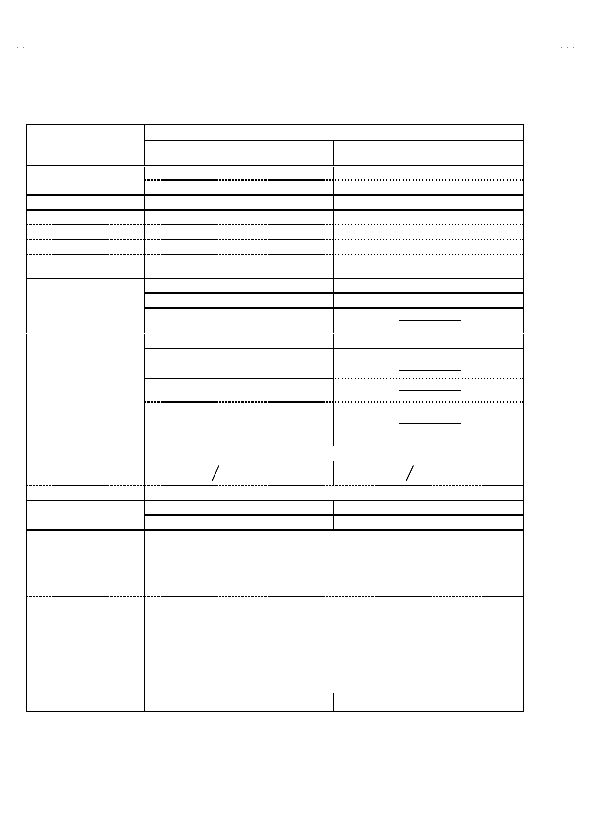
SPECIFICATIONS
Item
AV32 X2 5E US / AV3 2X2 50 EUS / AV28X25E US
Content
AV32 X2 5EIG Y / AV28 X25EIG Y
AV32 X2 5EK GY / AV 28X 25EKGY
32 ”) : 85. 5cm×55.0cm×56 .8c m
(28 ”) : 78. 0cm×50.9cm×49 .9c m
Mass (32 ”) : 54. 2k g / (28” ) : 40.2kg (32”) : 54. 2kg / ( 28” ) : 40. 2k g
TV RF Syste m CCIR ( B /G, D/ K, L, L’,I) CCIR ( I )
Colour Sy stem PA L / SEC A M / NTSC ( Only in EXT mo de ) PA L / NTSC (On ly in EXT mode)
Stere o Sy st em
Teletext System Fastext (UK syst em) / TOP (German syst em)
Receiving Frequency
Intermediate Frequency
Colour Sub Carr ier Fr eq.
Power Input
Power Consumpti on
Aerial Input Term
Picture Tube
Hi gh Vo l t ag e 31.0kV (at zero beam current)
Speake r
Au dio Output 7.5 W + 7.5 W
EX T-1 /EXT -2/E XT-3 ( I N/ OUT)
EXT-4 (Input)
A2 (B /G, D/ K) / NICAM (B/G, I, D/K, L) NICAM ( I )
WST(world standard system)
VHF : 47 MHz ~ 470MHz VHF : 47MHz ~ 470MHz ( EI model )
UHF : 470MHz ~ 86 2MHz UHF : 47 0MHz ~ 86 2 MHz ( EK / E I model )
• Fr enc h c able TV c han n el of br oa dcas t
fr eq ue ncies 1 16~ 1 72MH z & 220~ 46 9MH z
VIF Carr ier : 3 8.9MHz(B/G, D / K, I , L ) / 33.95MHz VIF C arr ier : 3 8. 9MHz
SIF Car r i er : 33 .4MH z(5.5 MHz : B/G ) SIF Carrier : 32.9MHz (6.0MHz )
32 .9 MHz( 6. 0MHz : I )
32 . 4MHz(6. 5MHz : L, D/K)
40.45 MHz ( 6 .5MH z : L ’)
PAL : 4.43 MHz PAL : 4. 43MH z
SE CAM : 4.40625MHz / 4.25MHz
NT S C : 3.58MHz / 4.43MHz NT S C : 3.58MHz / 4.43MHz
AC 2 20V~2 40V , 50Hz
187W (Max)
(32") (28 ” ) (32") (28”)
132W (Avg)
75 Ωun ba l anc ed, C oaxial
(32 ”) : V i ew ab l e ar e a 7 6cm ( meas ured di ag on ally)(32”) : V iewable are a 7 6cm ( meas ured di agon all
(28 ”) : V i ew ab l e ar e a 6 6cm ( meas ured di ag on ally)(28”) : V iewable are a 6 6cm ( meas ured di agon all
1.0kV
+
-1. 5kV
13 cm ×6.5cm , Ova l type×2
21 -p in E ur o c onnector (SCART s o cket)×3
Vide o : Vp-p 75Ω(RC A pin jack)
Au di o (L /R ) : 50 0m Vr ms(- 4d Bs), High Im pe dance (RC A p in j ac k)
S / Vide o Y : 1Vp- p P OSITI VE ( N eg ative sy nc Pr ovide d, when termi nat ed wit h 75Ω)
C : 0 .3V p-p ( B urst si gn al, wh en terminat ed with 75Ω)
178W (Max)
125W ( Av g)
32”) : 85. 5cm×55.0cm× 56 .8cmDimensions ( W××××H××××D )
(28”) : 78. 0cm×50.9cm×49 .9cm
Fastext (UK system)
WST(world standard system)
187W (Max)
132W (Avg)
178W (Max)
125W (Avg)
AUDIO OUT (Va riable)
Headphone jack
Remote Control Unit
0~1Vrms, Low Impedance (RCA pin jack×2)
St ereo min i jac k (φ3.5mm )
RM-C54 (AAA/ R 03 dry cel l batt er y×2) R M-C 55 (AAA/R0 3 dry cell b att er y×2)
De sign & sp eci fic ations are subje ct to cha ng e wi thout notic e .
2
No.51994
Page 3
A
V32X25EUS / AV32X250EU
S
A
A
A
V32X25EIGY / AV32X25EKGY
V28X25EUS / AV28X25EIGY
V28X25EKGY
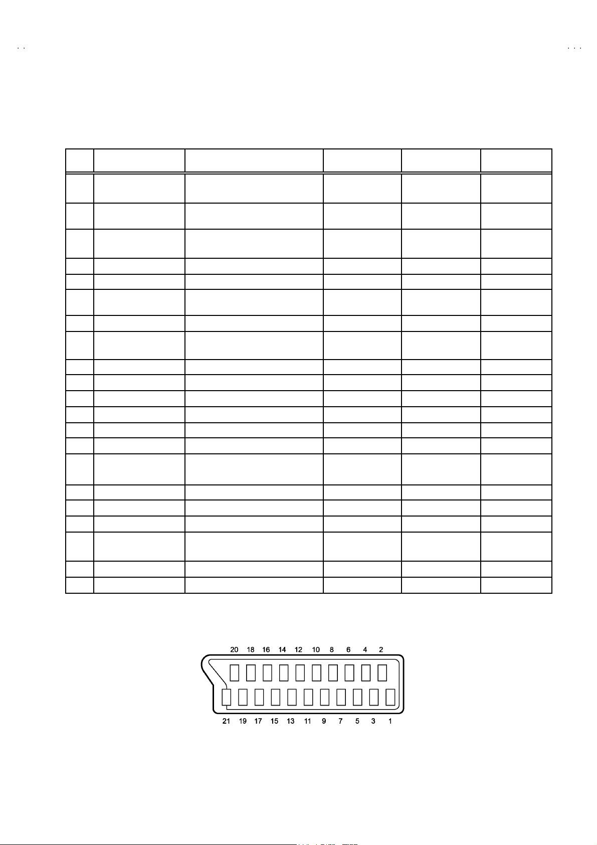
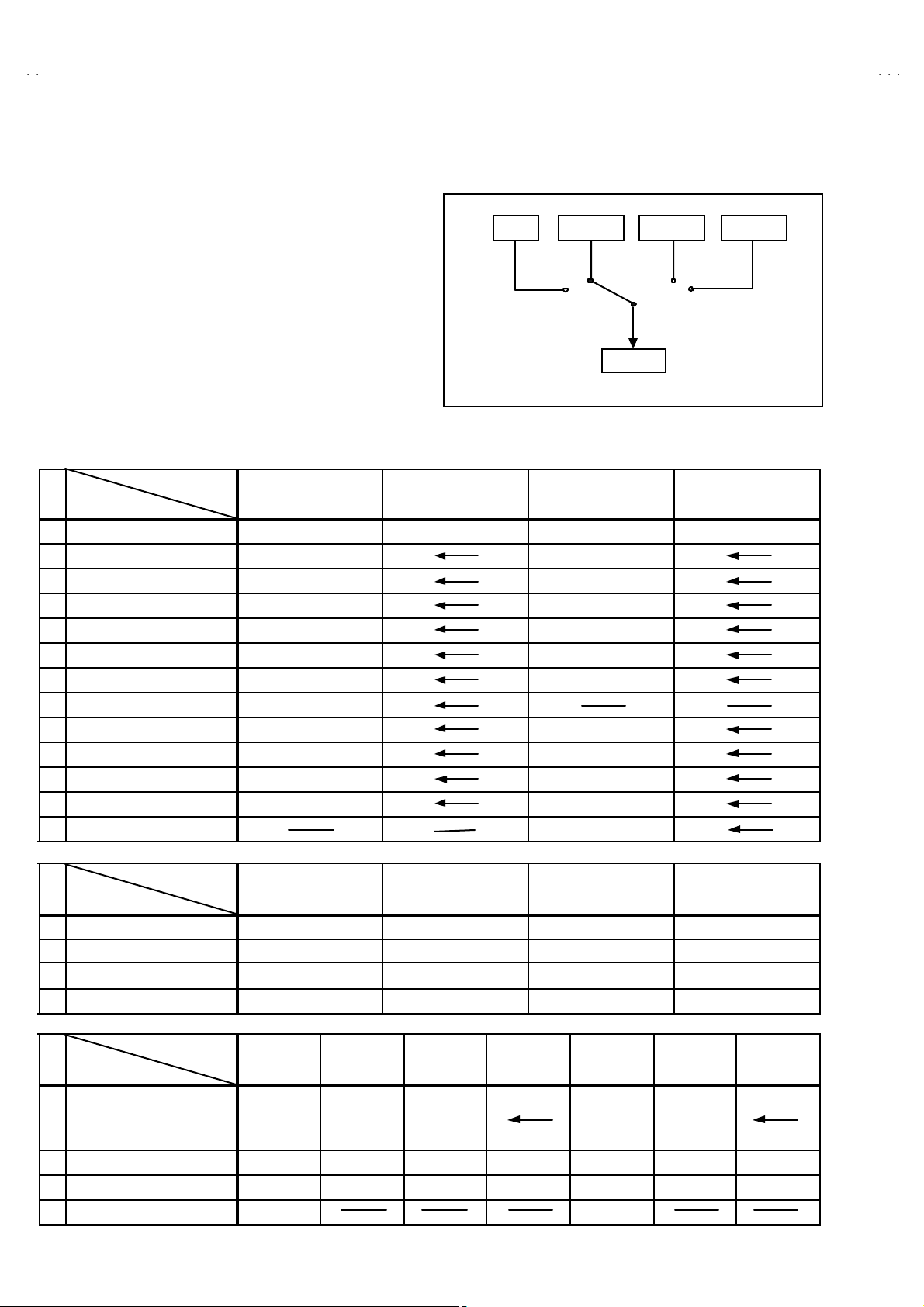
■■■■21-pin Euro connector (SCART socket) : EXT-1 / EXT-2 / EXT-3
(P-P= Peak to Peak, B-W= Blanking to white peak)
Pin
Signal Designation Matching Value EXT-1 EXT-2 EXT-3
No .
1 AUDIO R o ut put 50 0m Vr ms( N om i na l),
Low impedance
2 AUDIO R in put 500m Vr ms( Nominal),
High i m pe dance
3 AUDIO L o utput 50 0m Vr ms( N om i na l),
Low impedance
4 AUDIO G ND ○○○
5 GND (B)
6 AUDIO L input 500mVrms(Nominal),
High i m pe dance
7B input 700mV
8 FUNCTON SW
(SLOW SW)
9 GND (G)
10 SCL3 NC ○ NC
11 G in put 70 0mV
12 SDA3 NC ○ NC
13 GND (R)
14 GND (YS) ○○NC
15 R / C input R : 700mV
16 Ys i n put
17 GND(VIDEO output) ○○○
18 GND(VIDEO input) ○○○
19 VID EO outpu t 1V
20 VIDEO / Y inp ut 1V
21 COMMON G ND ○○○
Low : 0-3V, High : 8-12V, High
impedance
C : 300mV
Low : 0 - 0.4, High : 1 - 3V, 75Ω○ ○
, 75Ω○○NC
B- W
, 75Ω○○NC
B- W
, 75Ω
B- W
, 75Ω
P- P
(Nega tiv e g oi n g s ync ), 75 Ω○
P- P
(Nega tiv e g oi n g s ync ), 75 Ω○ ○ ○
P- P
○
(TV OUT)
○○○
○
(TV OUT)
○○○
○○○
○○○
○○○
○○○
○
(only R)
(TV)
○
(LINE O UT)
○
(LINE O UT)
○○
○
(LINE O UT)
NC
NC
(only C )
NC
NC
[Pin assignment]
No.51994
3
Page 4
A
V32X25EUS
A
A
V32X250EUS
V28X25EUS
SAFETY PRECAUTIONS
1. T he des ign of th is prod uct con ta in s sp ecial har d ware , many
circuit s and components specially for safety purposes. For
con tinu ed pr ot ection , n o c han g es sh ou ld b e ma de to the o rig i nal
d esi gn un les s a uth or i zed i n w riti n g by th e ma nu fact urer.
Replacem en t par ts must b e id ent ic al to thos e u sed in th e or i gin al
ci rcu its. S ervi ce sho ul d b e p erformed by qu alif ied p ers onnel
on ly.
2. Al te rati on s of t he desig n or circui tr y of t he pr oducts sh oul d not be
made. Any design alterations or additions will void the
manu fact ur er 's warrant y and w i ll f urth er r elieve t he ma nufac tu rer
of r esp onsi b ility for perso nal inj ur y or p rop erty d amag e r esul t ing
th erefr om.
3. M an y el ectrical an d m ec h ani cal parts i n th e pr od uc ts ha ve
special safety-related characteristics. T hese characteristics are
oft en no t e v i den t f r om vi s ua l insp ecti on nor ca n t he pr o tect ion
aff or de d by them nece ssarily b e ob tai n ed by us ing rep lacem en t
com po ne nts rated f or hi g he r vo l tag e, watt ag e, etc. R ep l acement
p arts whic h ha v e th ese s p ecial s afet y ch ar ac t er ist ics ar e
ide ntified i n the parts li st of S ervice manua l. El ectric al
components having such features are identified by shading
on t he sche mat ic s and by (!!!! ) on the parts list in Service
manual. The us e of a s ub sti tu te rep lacem en t which do es n ot
h ave th e s ame saf ety ch ar act er ist ics as t he reco mmen de d
replac em ent part shown in th e p ar ts list of S er v ice m an ual m ay
cause shock, fire, or other hazards .
4. Don't short between the LIVE side ground and ISOLATED
(NEUTRAL) side ground or EARTH side ground when
repairing.
Some model's power circuit is partly different in the GND. The
diff er enc e of th e GND is s ho wn b y th e LIV E : (") side GND , the
ISO LATE D(N EUTRAL) : (#) si de GND and EARTH : ($) side
GND. Do n't s h or t bet we en th e LIV E sid e GN D an d
ISO LATE D(N EUTRAL) side GND or EART H side GND an d
n ever m ea sur e w it h a mea sur i ng appa r atus ( osci lloscop e etc.)
th e LI VE sid e GND and IS OLA T ED(NE UTR AL ) side G ND or
EARTH side GND at the s ame time.
If above note will not be kep t, a fuse or any parts will b e broken.
5. If any repair has been made to the chassis, it is recommended
th at t he B1 s et ting shou ld b e ch ecked or adju ste d ( Se e
ADJUST M ENT OF B 1 POW E R SUPPL Y).
6. The high vol ta ge app lie d t o th e pi ctu r e tu be must con form with
th at s p ec ifi ed i n S er v ice m an ual. E xcessi ve h igh voltag e can
cau s e an i ncre ase in X-Ray em i ssi on , ar c i ng an d possible
component damage, therefore operation under excessive high
voltage conditions should be kept to a minimum, or should be
preve nt ed. If s evere arc in g occurs, remove t he AC pow er
immed i ate ly and de termine th e ca use by vis ua l insp ect ion
(inc or r ect install at ion, cr ac ked or melte d high volt age har n es s,
p oor so ldering, et c .) . To m ai nt ain the p rope r min imu m l e v el of
sof t X- R ay emis si on, c omp on en ts in th e hi gh voltag e circui tr y
incl ud i ng t he pic t ur e tu be must b e t he e xact r ep lac em e nts or
alte rn at ives ap prove d by the ma nuf act urer of th e c om pl et e
prod uct.
7. Do n ot c hec k high volt ag e b y draw ing an arc. Use a high volt ag e
meter or a hi g h v ol tag e pr ob e wit h a V TVM. D isc ha rg e th e
picture tube before attempting meter connection, by connecting
a cl i p lead to the grou nd frame a nd c onn ecting th e oth er end of
the lead through a 10kΩ 2W resi sto r to the an od e butt on .
8. W hen service is r equ ire d, ob ser ve th e or i gina l lea d dress. Ex tr a
prec aut ion sh ould b e g i ven t o as sure cor r ec t l ea d dres s in th e
high vol tag e ci r cuit a r ea. W here a s hor t c ircui t h as occu rre d,
th ose co mponent s tha t indic a te evi de nc e of ove r hea ting sho uld
b e r e pl aced. A l wa ys us e th e ma nuf act ur er 's r ep lac em en t
components.
9. Isolation Check
(1) Di electric Strength Test
(2) Leakage Current Check
AV32X25EUS / AV32X250EUS / AV28X25EUS
(Safety for Electrical Shock Hazard)
Af ter r e- as s embling th e p r odu c t, alw ays per f orm an is olat io n
ch ec k on the ex po sed me tal p ar ts of t he c abin et ( a nte nn a
ter m ina ls, video /au dio inpu t and ou tput t erminals, C on trol kn obs,
metal cabin et, s crewhe ad s, ea r ph one j ac k, contr ol shaf ts , etc.)
to be s u re the p r odu c t i s s af e t o o pe r ate with ou t d an ger of
elect rical shoc k.
The i so l ati on be tween the AC pr im a ry ci rcu i t an d all metal p ar ts
exp osed t o th e us er, p arti c ularly an y expos ed met al p art having a
retu rn p ath to t he chass is s ho ul d withs tan d a vol t age of 3 000 V
AC (r.m.s.) for a period of one second.
(. . . . W it hstan d a vo lt ag e of 110 0V A C (r.m. s .) to an ap plianc e
rate d up to 12 0V , an d 3 00 0V AC ( r .m. s.) to an ap pl i an c e rat ed
200V or more, for a period of one second.)
This meth od of test requires a t est equipment n ot g enerally found
in t he s er vic e trade.
Plug th e AC l in e c ord d irect ly into th e AC ou tlet (do n ot use a line
isol ati o n transf ormer du ring this ch eck.) . U s in g a " Lea kag e
Curr ent Teste r", me asure th e lea kage cu rre nt f rom each exp osed
metal p ar t of the c a bi ne t, p art icularly any expos ed me tal part
h avi ng a re turn pa th to t he c h assis , t o a k n ow n go od ea rt h
grou nd (wa ter pi p e, e tc.) . An y l eaka ge curren t m ust n ot e xc eed
0.5mA AC (r.m.s.).
Howev e r, i n tropic al ar ea , th is mus t no t exc e ed 0.2 mA AC
(r.m.s.).
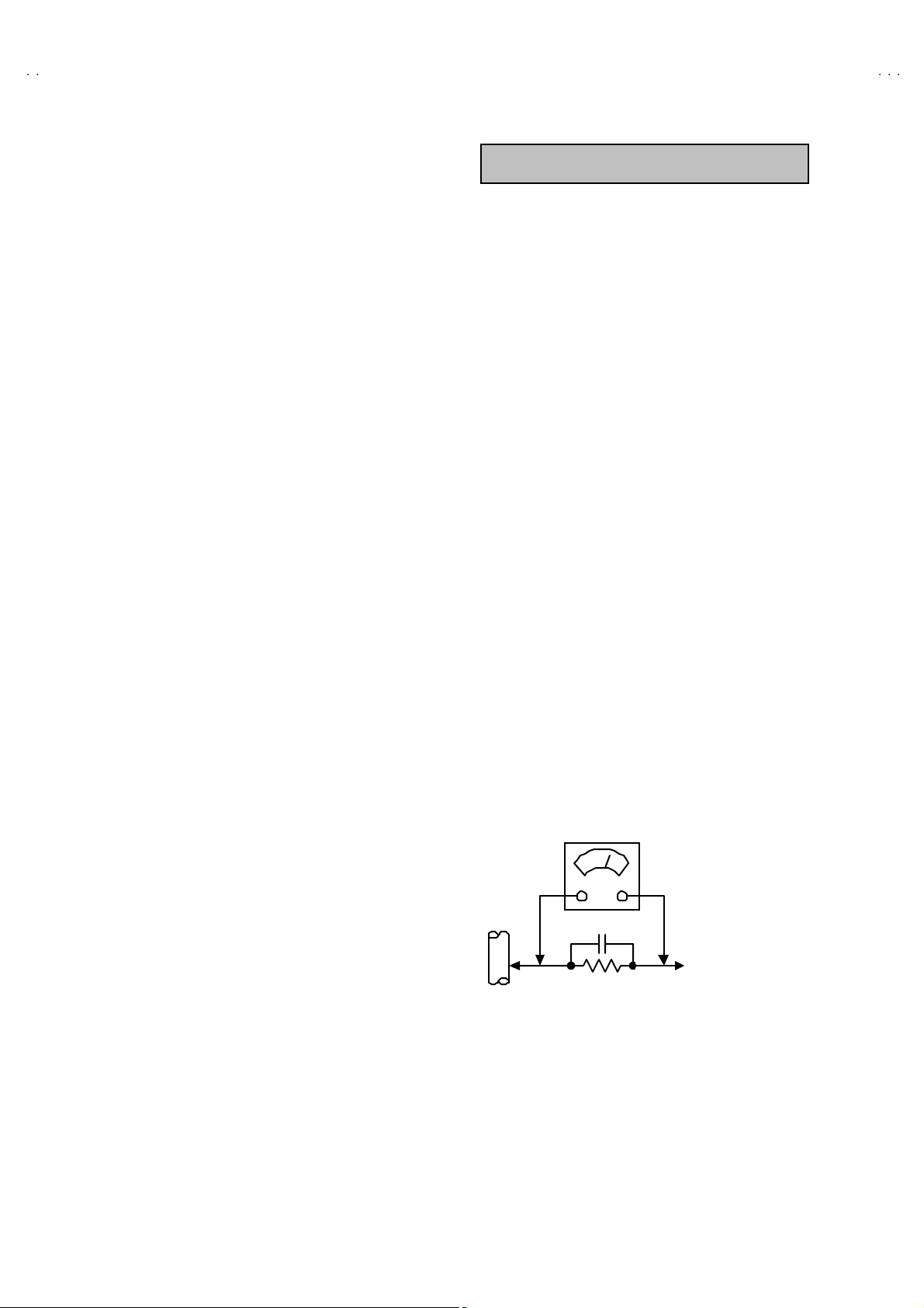
"""" Altern at e Che ck M ethod
Plug th e AC l in e c ord d irect ly into th e AC ou tlet (do n ot use a line
isol ati o n transformer during t his c he ck.). Use an AC v o lt me ter
h avi ng 1 000 oh ms pe r volt or m or e sens it i vity i n th e fo llowi ng
mann er . C on nec t a 1 500Ω 10W res ist or par a lle le d b y a 0 .1 5µF
AC-type c apa cit or bet ween an expo sed met al pa rt a nd a kno wn
g ood e ar th gr o un d ( water pi pe , etc.). Meas ure th e AC vo lt ag e
acr oss th e r es ist or with th e AC vo l tm eter . M ove th e r esis tor
con nec tion to e ach ex p os e d me tal par t, p art ic ularly any exp osed
metal p ar t hav in g a r etu rn pat h to t he chass is, an d m easu re th e
AC vol tag e ac ro s s the r es ist or . Now, re ver s e th e plu g in th e AC
ou tl et and r e peat eac h mea suremen t. Any volt ag e me as u re d
must no t e xceed 0 .7 5V AC (r .m.s.). This c orre spo nds to 0 .5mA
AC (r.m.s.).
Howeve r, in tropica l area, this must not exceed 0.3V AC ( r.m.s.).
This corresponds to 0.2mA AC (r.m.s.).
AC VOLTMETER
(HAVING 1000 Ω/V,
OR MOR E SENSIT IVITY)
0.15μF AC-T YPE
PLACE THIS PROBE
1500 Ω 10W
GOOD EARTH GROUND
ON E A C H EX PO SE D
ME T AL PA RT
4
No.51994
Page 5

A
A
SAFETY PRECAUTIONS
V32X25EIGY / AV32X25EKGY
V28X25EIGY / AV28X25EKGY
AV32 X2 5EIG Y / AV32 X25EKGY
AV28 X2 5EIG Y / AV28 X25EKGY
1. The d esign of thi s pro du ct c ont ai ns spe c i al hard ware and ma ny
circuit s and components spe cially for saf ety pur poses. For
con tinu ed pr ot ection , n o c han g es sh ou ld b e ma de to the o rig i nal
d esi gn un les s a uth or i zed i n w riti n g by th e ma nu fact urer.
Replacem en t par ts must b e id ent ic al to thos e u sed in th e or i gin al
ci rcu its. S ervi ce sho ul d b e p erformed by qu alif ied p ers onnel
on ly.
2. Al te rati on s of the desig n or circ ui tr y of the pr od uc t should no t b e
made. Any design alterations or additions will void the
manu fact ur er 's warrant y and w i ll f urth er r elieve t he ma nufac tu rer
of r esp onsi b ility for perso nal inj ur y or p rop erty d amag e r esul t ing
th erefr om.
3. M an y electr ical a nd me cha nical p arts in the prod uct h av e spe ci al
saf ety- r el at ed charact erist ic s. Thes e ch aracter istic s are oft en not
evi d ent fr om visu al insp ecti o n no r c an th e pr otect ion af for de d by
th em n ecess ar y b e o bta in ed by using r e plac em ent c omponen ts
rate d for hi gh er v ol ta ge, watta ge, etc . R e pl acemen t p arts wh ic h
WARNING
h ave th ese spe ci al saf et y c harac teris tic s ar e i d ent if ied in th e
Pa rts Lis t of S ervi ce Manu al. El ectr ical compon en ts having suc h
fe atur es are i de nti fied by shad in g on the sche ma tic s a nd by (!)
on t he P arts Lis t i n the S ervi ce Man ual . T he use of a sub stitut e
replac em ent whic h d oes no t hav e th e s am e saf ety
ch ar ac ter i sti cs as the r e c om mend ed r epl ace m ent p art sho wn i n
th e Par ts Li st of Se rvice M an ual m ay cau se shock , fire, or ot her
hazards.
4. The lea ds in th e p r odu cts ar e r ou ted an d d res sed with t i es,
cl am ps, tu bi ng ’s , b ar ri e rs and t he like t o be s epa ra ted fr om live
p arts, high t em pe ra tur e pa rts, m oving par ts and / or sh ar p ed ge s
for t he p reven tion of e l ectr i c sh oc k and fire h azard. W he n
ser vice i s requ ired , the or igin al le ad r outi n g and dre ss s h ou ld b e
ob ser v ed , and it should b e co nfirmed t hat th ey h ave b ee n
retu rn ed to no rmal , aft er re- asse mb li n g.
1. The eq ui pm e nt has b een d esigned a nd manu fact ured to me et i nternati o nal saf ety stand ar ds.
2. It is t he l eg al r esp onsib ility o f th e re pa irer t o ensure th at thes e s afet y sta nd ar ds are m aint ai ne d.
3. Rep ai rs mu st b e m ad e in acc ordan ce with th e rel e vant saf ety st an dards .
4. It is essen tial t hat saf ety critical c ompon ents ar e replac ed by a pp ro v ed pa rt s.
5. If main s vol t age s elec tor i s p r ovide d, ch eck s etti n g for loca l voltag e.
No.51994
5
Page 6
A
V32X25EUS / AV32X250EUS
A
A
A
V32X25EIGY / AV32X25EKGY
V28X25EUS / AV28X25EIGY
V28X25EKGY
FEATURES
"
New c hass i s d esi gn ena ble us e of an interac tive on s creen
control.
"
The TELETEXT SYSTEM has a built-in FASTEXT (UK system),
TOP (German syst em) and WST (world standard system)
system.
"
Be caus e th is T V unit corr es p on ds t o multiple x br oa dc a st, u ser s
can enjoy music programs and sporting events with live realism.
In ad di tion , BI LINGUAL pr o gr am s can b e h ear d in th eir original
language.
"
Users can make VCR dubbing of picture and sound by controlling
th e AV se l ec to r t o s el ect a n opt ional s our ce at the E XT-2 ou tpu t
sh own i n fi gu re.
MAIN DIFFERENCE LIST
TV EXT-1 EXT-3
EXT-2
EXT-4
Model Name
!
Part Name
MAIN PW B ASSY SMF-1 40 4A-U2 SMF-1944A-U 2 SMF -1403A-U 2 SMF-194 3A- U2
POWE R & DEF PW B AS SY SM F-240 4A- U2 SMF-2403A-U 2
CRT SOCKE T PWB AS SY SMF-3404A-U 2 SM F-3 40 3A- U2
FRONT CONTROL PWB ASSY
SIDE CONTROL PWB AS SY SMF-8104A-U 2 SM F-8 10 3A- U2
!
ITC T U BE W76 ER F042 X04 4 W66 QD E993 X925
!
DEGA US SING COI L QQW 0066 -0 01 QQW 0100 -0 01
!
ROTATIO N CO IL QQW 0 130-001
!
FBT QQH 0127 -001 QQH0 126- 001
!
REAR COVE R LC1131 6- 00 1A- U LC1128 2- 00 1C - U
CUSH ION AS SY LC1137 3- 00 2A- U LC1131 8- 00 2A- U
PA CKING CASE AE M1002- 07 9-E AE M1002- A76 -E
CORNE R POST AE M3119- 00 3A- E
Model Name
!
Part Name
!
FR ON T CABINET AS SY LC1136 0- 00 4A- U LC1136 0- 00 3A- U LC1131 3- 00 4B- U LC1131 3- 00 3B- U
!
POWER CO RD QMPK160-185-JC QMPN130-185-JC QMPK160-185-JC QMPN130-185-JC
JVC M AR K LC4125 0- 00 2C - C LC4 1250- 001C - C LC4 1250- 002A- C LC4125 0- 00 1C - C
REMOTE CONTROL UNIT RM-C54H-1C RM-C55H-1C RM-C54H-1C RM-C55H-1C
AV32 X2 5EUS
AV32 X2 50EU S
AV32 X2 5EIG Y
SMF-8404A-U2 SMF-8403A-U2
AV32 X2 5EUS
AV32 X2 50EU S
AV32 X2 5EKGY
AV32 X2 5EIG Y
AV32 X2 5EKGY
AV28 X2 5EUS
AV28 X2 5EIG Y
AV28 X2 5EUS
AV28 X2 5EKGY
AV28 X2 5EIG Y
AV28 X2 5EKGY
Model Name
!
Part Name
!
INST BOOK
!
RATING LABEL
EURO LABEL
WARNING LABEL
!
6
AV32X25EU S AV32X250EUS AV32X25EIGY AV32X25EKGY AV 28X25EU S AV28X25EIGY AV28X25EKGY
LC T1184- 00 1A-U
LC T1185- 00 1A-U
LC T1186- 00 1A-U
LC1 141 4-00 3A- U LC1 137 2- 004A -U LC1136 4- 00 8A-U LC1136 4- 00 7A- U LC1 141 4- 00 4A-U LC1136 4- 01 0A-U LC1136 4- 00 9A- U
AEM1064-017-U AEM1064-020-U AEM1064-019-U AEM1064-018-U AEM1064-021-U AEM1064-023-U AEM1064-022-U
LC3 078 9-00 2B- U LC3 078 9-00 2B- U
LC T1185- 00 1A-U LCT11 87- 00 1A-U
LC T1184- 00 1A-U
LC T1185- 00 1A-U
LC T1186- 00 1A-U
LC T1187- 00 1A-U
No.51994
Page 7
A
S
A
A
A
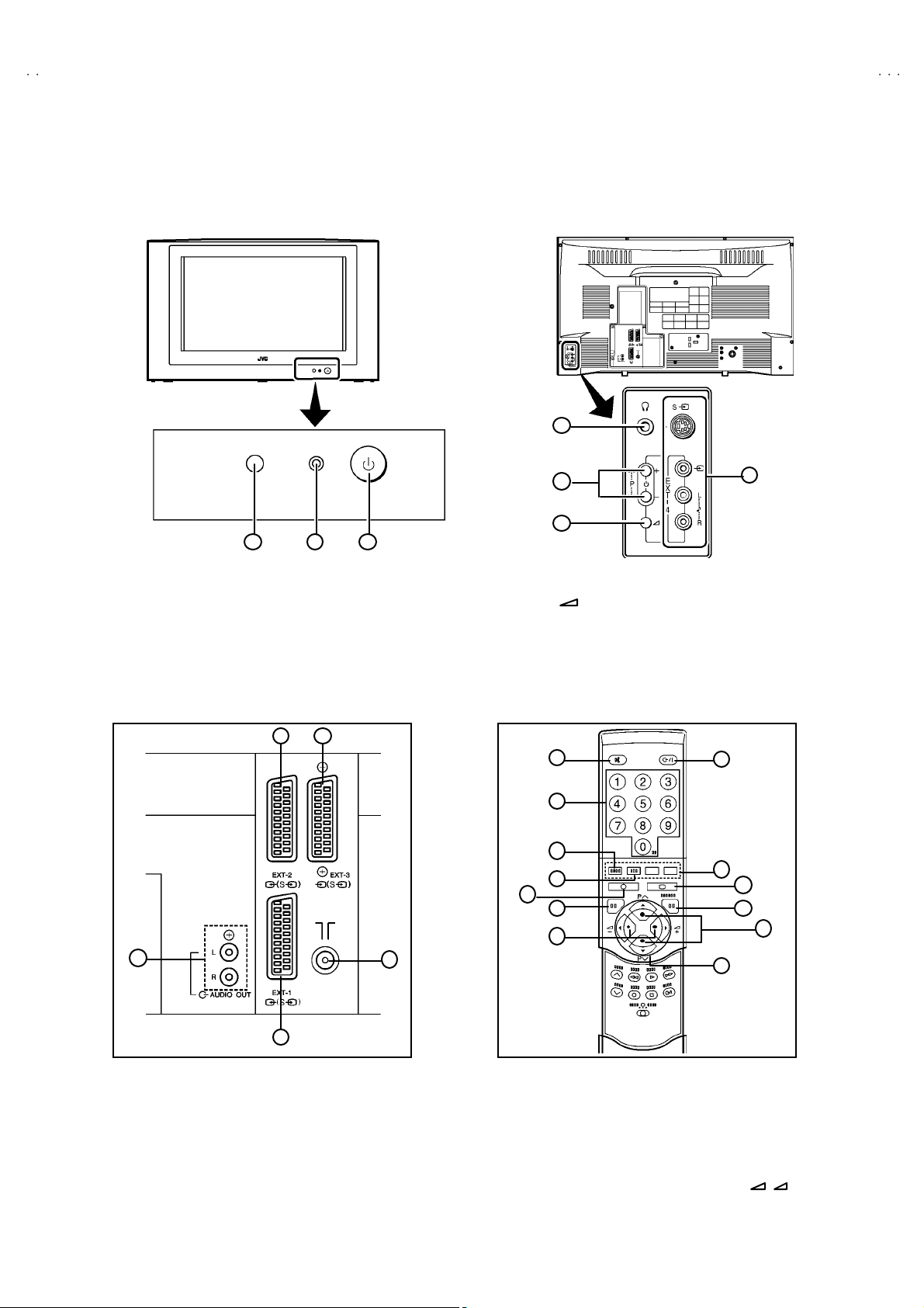
FUNCTIONS
(FRONT) (SIDE)
4
V32X25EUS / AV32X250EU
V32X25EIGY / AV32X25EKGY
V28X25EUS / AV28X25EIGY
V28X25EKGY
5
6
1 2
① R em ote co ntrol se nsor
② Power lamp
③ Main power butt on
3
∨/∧
⑤ P
buttons / -/+ bu ttons
⑥ (Volu me ) but ton
⑦ EXT-4 terminal
④ Headphone jack (mini jac k)
(REAR PANEL) (REMOTE CO NT ROL UNIT)
32
5
4
1
2
3
4
5
6
7
8
9
13
7
10
11
12
1
① EXT-1(IN/OUT) Terminal
② EXT-2(IN/OUT) Terminal
③
EXT-3(IN/OUT) Terminal
④
Aerial Sock et
⑤
Au di o out put t erm ina l
① Mu ting K ey
② Number Key
③
ZOOM Key
④
Hyper Sound Key
⑤
Information Key
⑥ TV Key
⑧ St and by (p ower) Key
⑨ Colour Key
⑩
TEXT Key
⑪
K/MENU Key
⑫
PR Channel ∨/∧Key
⑬
FUNCTION ( / / P∧/ P∨) Key
+ -
⑦ Volume -/+ Key
No. 51994
7
Page 8
A
V32X25EUS / AV32X250EUS
A
A
A
V32X25EIGY / AV32X25EKGY
V28X25EUS / AV28X25EIGY
V28X25EKGY
SPECIFIC SERVICE INSTRUCTIONS
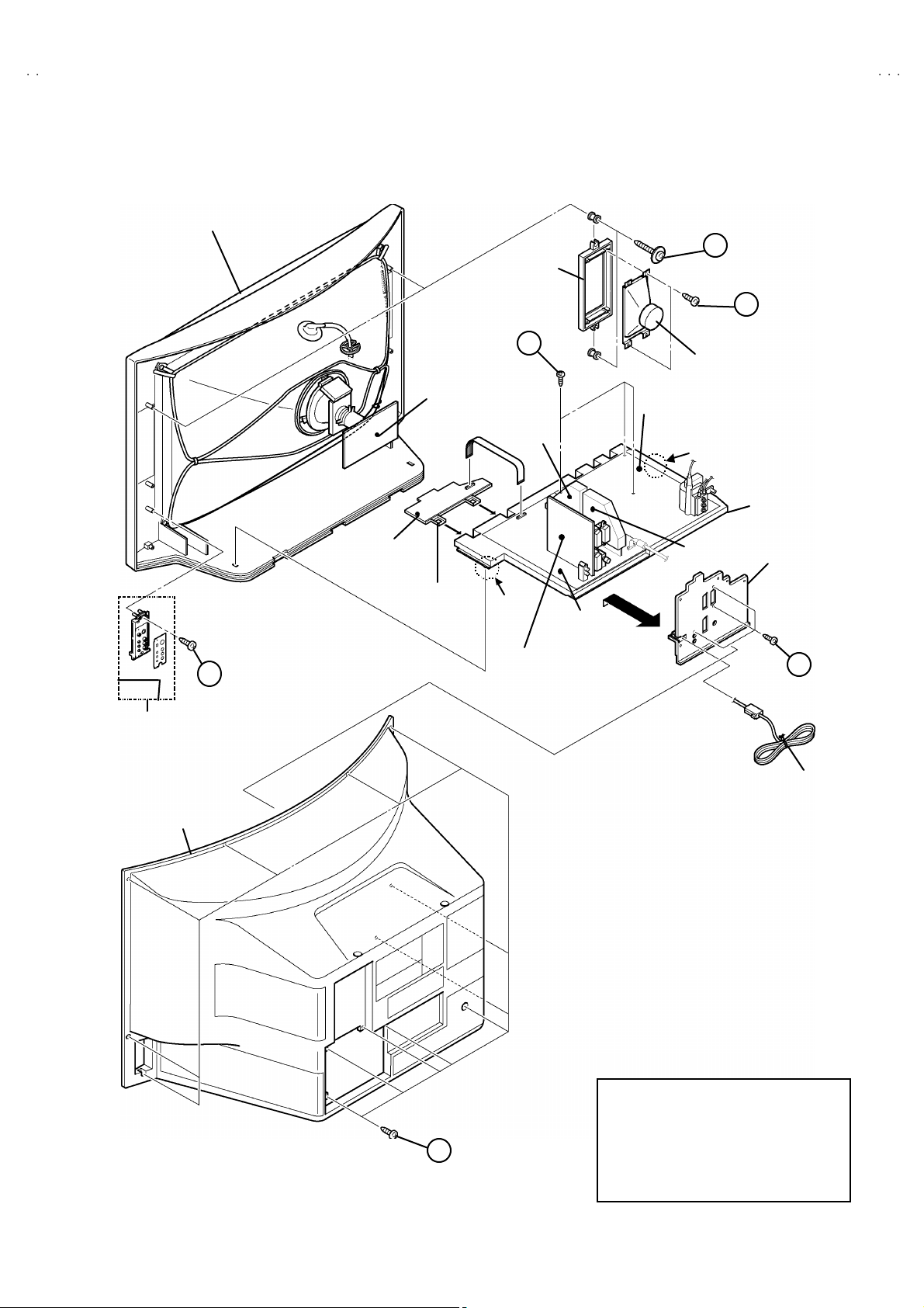
DISASSEMBLY PROCEDURE
REMOVING THE REAR COVER
1. Unp lu g t he po we r c ord.
2. Remove the 13 screws marked A as s hown i n t he F i g. 1.
3. W i thdr a w t he rear cover towa rd you .
REMOVING THE SIDE CONTROL JACK ASSEMBLY
"
After removing the rear cover.
1. Remove the screw marked B as shown in the Fi g.1 .
2. W hile s l ight l y r ai s e th e side c ontr o l jack asse mb ly, r em ov e th e 2
claws under the side control jack assembly.
3. Disc onn ect th e c onn ecto r “SR ”, “ SL”, “ S”, “F” and “CN01 6” as
shown in Fig 2.
REMOVING THE SIDE CONT ROL PWB
"
Af ter remov i ng th e re ar cov er an d sid e co ntr ol j ac k ass embly.
1. Remove th e 3 claws C from b ack side of the side control jack
asse mb l y as s hown in Fi g. 2.
2. Pu ll out the SI DE C ON T RO L PW B.
REMOVING THE CHASSIS
" After removing the rear cover.
1. Slight l y r ai se th e bo th si de s of th e c hassis by h and and re mo v e
th e tw o c laws u nd er the b oth sid es of the chass is from t he fr o nt
cab inet .
2. W i thdr a w t he chass is back w a rd .
(If n ecessary, take off the wire clamp, connecto rs etc.)
REMOVING THE POWER & DEF. PWB
"
After removing the CHASSIS.
1. Remove the 3 sc r ews m arked D a s sh own in the Fig.1 .
2. Remove the PO W ER & D EF. PW B upper .
(If n ecess ary, ta ke o ff the wire c lamp, co nnectors, etc.)
REMOVING THE SPEAKER
" After removing the rear cover.
1. R em ove t he 2 scr ew s marked E, and rem ove the sp eake r hold er
as s hown in F i g. 1.
NOTE : When rem oving th e scr ew s marked E of t he sp eaker ho lder
remove t he lower si de s cr ew fir s t, an d t hen r em ov e the
up per one .
2. Remove the 2 screws F a tta ching th e sp ea ker.
3. Follow th e s ame st eps wh en r em oving th e oth er ha nd spe aker.
REMOVING THE AV TERMINAL BOARD
"
After removing the rear cover.
1. R em ove th e 3 scr ew s marked G as show n i n t he F ig . 1 .
2. Remove the 2 claws marked H under the CHASSIS as shown in
Fig. 3.
3. Remove the AV TERMINAL BOARD slightly in the directio n of
arrow I as shown in Fi g. 3.
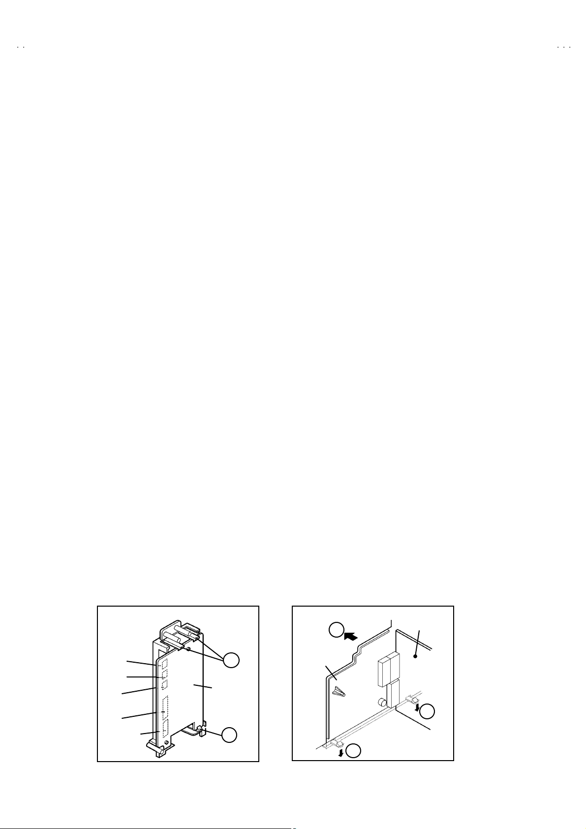
CHECKIN G THE PW BOARD
To c h eck the b ack side of th e PW Boar d.
1) Pull out the chassis. (R efer to REMOVING THE CHASSIS).
2) Erect t he c hassis vertically so that you c an easily check the
b ack side of th e PW Boar d.
[CAUTION]
"
When erecting the chassis, be caref ul s o that there will be no
con tact ing with ot her PW Boar d.
"
Be fore tur n in g on pow er , ma k e sur e tha t the wire co nn ecto r i s
prop er ly c on nec ted .
"
W hen condu cting a check with p ow er supplied , be sur e to c onfi r m
th at t he CRT E ARTH W I RE (BRAID ED AS S’Y) i s co nne cted t o
th e C R T SOC KE T PW b oar d.
WIRE CLAMPIN G AND CABLE T YING
1. Be sure t o clamp th e wire.
2. N ever rem ove th e c able tie use d f or ty i ng th e wires to ge the r.
Sh oul d it be i n adve rt ent ly remove d, b e sure to ti e th e wir es wit h
a n ew c able ti e.
I
Connector
SR
SL
S
F
CN0 16
C
SI DE
C ONT RO L
PWB
C
(Back view)
Fig . 2
8
No.51994
AV TERMINAL
BOARD
H
Fig . 3
AV SW PWB
H
Page 9
A
S
A
A
A
FRONT CABINET
(
)
(×3)
(×2)
(
)
SP EAKER
HOLDER
V32X25EUS / AV32X250EU
V32X25EIGY / AV32X25EKGY
V28X25EUS / AV28X25EIGY
V28X25EKGY
E
F
×
2
Fig.2
SI DE C ONTR OL
JACK ASSEMBLY
D (×3)
CRT
SOCKET
PWB
FRONT
C ONT RO L
PWB
C ONT RO L
BAS E
B
MICOM
PWB
CLAW
MAI N
PWB
AV SW
PWB
POWER & DEF.
PWB
SI DE
SP EAKER
CLAW
10 0Hz
PWB
CHAS SIS
AV TERMINAL
BOARD
G
POWER CORD
REAR COVER
A
×
13
Fig . 1
No.51994
Thi s expl o de d vi ew d escr i bes a bo ut 32”
models.
Alth ou gh 2 8” m ode ls ar e sli gh tly di ffe r ent
fr om th is f igur e, you can use the exp lod ed
vi ew f or di sass emb l ing t he 28 ” mod els in
same step as 32” models.
9
Page 10
A
V32X25EUS / AV32X250EUS
A
A
A
V32X25EIGY / AV32X25EKGY
V28X25EUS / AV28X25EIGY
V28X25EKGY
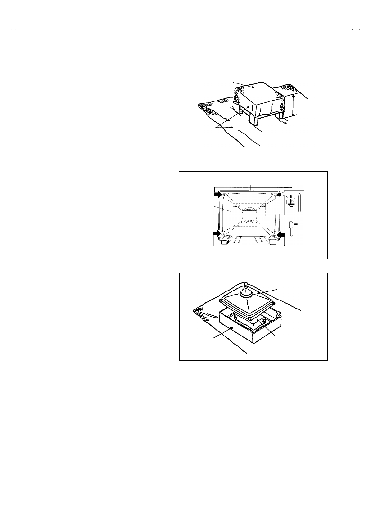
REMOVING THE CRT
∗
Replacem en t of the CR T sho ul d be p erformed b y 2 or m or e
p ers ons.
• After removing the cover, chassis etc.,
1. Putti ng the C R T c hange table on sof t cl oth , th e CRT c ha ng e tabl e
sh ould al so b e c overe d with s uch soft c lot h ( sho wn in Fi g. 8).
2. W hile kee pin g th e s urf ac e of C RT down , m ou nt the TV s et on t he
CRT change table balanced will as shown in Fig.9.
3. R em ove 4 sc re ws mar ked by arr o ws wi th a box typ e scr ew d ri ve r
as s hown in Fig. 9.
• Si nc e th e cab i net wi ll dr op w he n s crews h ave be en r em ove d, b e
sure t o su pp ort t he cab inet with h ands.
4. After 4 screws have been removed, put the cabinet slowly on
cloth (At this ti me, be carefully so as not to damage th e front
sur fac e of th e c abin et) sh own in Fig. 10.
• T he CR T sh oul d b e ass embled acc or di n g to th e o pp os i te
sequence of its dismounting steps.
∗
The C RT chang e t able sh ould pr ef erab l y b e small er t hat th e CRT
sur fac e, and i ts h ei gh t b e abo ut 35c m.
CRT CHAN GE TABLE
AP PROX.
35 cm
CLOTH
Fig. 8
CRT
CRT
CHA NGE
TABLE
BOX
TYPE
SCREW
DRI VER
CABINET
Fig. 9
CRT
CRT
CHANGE TA BLE
Fig. 10
10
No. 51994
Page 11

A
S
A
A
A
REPLACEMENT OF CHIP COMPONENT
! CAUTIONS
1. Avoid heating for more than 3 seconds.
2. D o n ot rub t he elec t ro des an d t he resi st p ar ts of the p att er n.
3. W hen rem oving a c hip par t, mel t th e s older adequ atel y.
4. D o n ot reuse a ch ip p ar t after removi ng it .
! SOLDERING IRON
1. U se a hig h ins ulati o n s older ing iron with a t hin po in ted end of it.
2. A 3 0w s older ing i r on is r ec ommended for easily r em ovi ng par ts.
!
REPLACE MENT STEPS
1. How to remove Chip parts
####
Resi st ors, ca pa cit o rs , etc
(1) As sh own in t he f igure, pu s h th e pa rt with tw ee zers and
alte rn at ely m elt th e sol de r at each en d.
(2) Sh if t w i th tweez e rs and r emo ve th e ch i p p ar t.
#### Trans ist o rs, dio des , va ria bl e r esistor s, etc
(1) Ap pl y e xt ra so ld er to each le ad .
SOLDE R SOLDE R
V32X25EUS / AV32X250EU
V32X25EIGY / AV32X25EKGY
V28X25EUS / AV28X25EIGY
V28X25EKGY
2. How to install Chip parts
####
Resi st ors, ca pa cit o rs , etc
(1) Apply sold er to th e p att ern a s indic ate d in the fig ure.
(2) Gr asp t he c h i p p art with twee zer s and pl ac e it on the s old er.
The n hea t and me lt th e so lder a t b oth ends of t he chip part.
#### T rans isto rs, dio d es , va ria bl e r esistor s, etc
(1) Apply sold er to th e p att ern a s indic ate d in the fig ure.
(2) Gr asp th e chip part w it h t we eze rs and p lace it on the so lder .
(3) First solder lead A as indica ted in t he figu re.
A
(2) As sh own in t he f igure, pu s h th e pa rt with tw ee zers and
alte rn at ely m elt th e sol d er at eac h le ad . S hift an d r em ov e the
chip part.
(4) Then so ld er l e ads B and C.
Note : A fte r re moving t he part , remove r emaining solder fr o m the
pattern.
C
A
C
No.51994
B
B
11
Page 12

A
V32X25EUS / AV32X250EUS
A
A
A
V32X25EIGY / AV32X25EKGY
V28X25EUS / AV28X25EIGY
V28X25EKGY
REPLACEMENT OF MEMORY ICs
1. Memory ICs
This TV use memory ICs. In the memory ICs, there are memorized data
for cor r ec tl y op er ati n g th e vid eo and def l ecti on circu its . W h en r ep lac ing
memory IC s , b e sure t o us e ICs writte n with th e ini ti al values of da ta.
2. Procedure f or replacing memory ICs
PROCE DURE
(1) Powe r off
Switch the p ower of f and un pl ug the p ower cord f ro m t he ou tlet.
(2) R ep la ce ICs.
Be sure to use memory ICs written with the init ial data values.
(3) Po we r o n
Plug th e pow er c ord i nt o the ou tlet a nd switch t he power on .
(4) C heck an d s et SY STEM CO NSTA NT SET :
It must not adjus t without signal.
****
1) Pr ess th e IN FO RMATI ON ke y and th e MUTING key of th e
REMOTE CONTROL UNIT simultaneously.
2) The SERVICE MENU screen of Fig. 1 will be displayed.
3) While th e S ER VICE ME NU is d is playe d, pres s th e
INFORMATION key and MUTING key s imultaneously, and the
SYSTEM CONSTANT SET screen of Fig. 2 will be display ed.
4) Check th e s e tting va lues of the S YSTEM CON STA NT SET of
Table 1. If the valu e is differe nt, se lect the s ettin g item with th e
FUNCTION U P/ DOWN ke y, an d s et t he c orrect value with the
FUNCTION - /+ ke y.
5) Press the MENU key to memorize the sett ing value.
6) Press t he INFORMATION ke y t wice, a nd retu rn t o th e normal
screen.
SE RV ICE MEN U
1. IF 2. V/C
3. A UDI O 4. D EF
5. VSM P RESET 6. S TAT US
7. P IP 8. -- -
9. SHIPPING (OFF) 0. BUS FREE
1 -9 : SE LE CT
SYS TE M C ONS TA NT S ET
1. DESTINATION EU
- /+ : STORE i : EXIT
OK
Fig.1
Fig.2
i
: EXI T
NAME OF REMOTE CONTROL KEY
(5) Setting o f re ceive chann e ls
Names of key
ke y
Se t th e r ec eive ch anne l.
For setting , refer to the OPE RATING IN S TRUC TIONS.
(6) U ser se ttings
INFORMATION
MU T I N G
iiii
Check th e us er sett in g values of T ab le 2, and i f sett in g v alue is
diff er ent , set the c orr ec t val u e.
For setting , refer to the OPE RATING IN S TRUC TIONS.
(7) Setting of SERVICE MENU
Ve rif y the set ti ng it ems of th e SE RVICE MENU of Tab le 3, and r ese t
ME NU
FUNCTION UP/ DOWN
OK
▼
▼
where n ecessary.
For setting , refer to the SE RVIC E ADJU STM ENTS.
FUNCTION -/+
▼
▼
12
No. 51994
Page 13

A
V32X25EUS / AV32X250EU
S
A
A
A
AV32X25EKGY
AV32X25EIGY
V32X25EIGY / AV32X25EKGY
V28X25EUS / AV28X25EIGY
V28X25EKGY
SETT ING VALU ES OF SY ST EM CO NS TANT SE T (TABLE 1)
Setting item Setting content Setting value Setting item Setting content Setting value
AV32X25EUS
AV 32X 250E US
DESTIN A TION
CRT TYPE 16:9 BBE YE S
EKEU EI
4:316 :9
AV28X25EUS
AV28X25EKGY
AV28X25EIGY
EU
PIC&TE XT NO
EK
DOLB Y NO
EI
NO
YE SNO
YE SNO
YE S
PURITY NO PROGRESSIVE NO
PICTURE TILT YES TDA9178 NO
DIGIP URE PRO NO TONE I C NO
PIP NO FLAT YE S
NO
1TUNERNO 2TUNER
YE SNO
YE SNO
YE S
NO
YE SNO
YE S
YE SNO
YE SNO
USER SETTING VALUES (TABLE 2)
PICTURE SE TTING EX T SETTI NG
TINT COOL
CONTRAST / BRIGHT
SHAR P / COLO UR
PICTURE FEATURES FEATURES
DIGITAL VNR AUTO
COLO UR S YST E M T V : Acco rdin g t o pr eset C H
4:3 AUT O ASPECT PA NO RAMIC
SOUND SETTING INSTALL
BA SS / T REBLE / BA LANCE LANGUAGE ENGLISH
HYPE R S OU ND
BB E
REFER to VSM PRESET
EXT : AUTO
CENTER
OFF
ON
ID
S-IN
DUB BING
SLEEP TIMER
BLUE BA CK
EDIT/MANUAL PRES ET CH only
BLANK
BLANK
EXT- 1→EX T-2
OFF
ON
The others : BLANK
SERVICE MENU SETING ITEMS (TAB LE 3)
Setting item Setting value Setting item Setting value
1. IF
2. V / C
3.A UDIO
(Do not adjust)
9.S HIPPI NG
(Do not adjust)
1. V CO
2. ATT ON /OFF
1. RGB BL K
2. W D R R
3. W D R G
4. W D R B
5. BRIGHT
6. CONTRAST
7. COLO UR
8. HUE
9. SHAR P
10. VC O A DJ .
11 . VID AGC
12 . SY C SL I
13 . A M OV I E
1. ER R LI MIT
2. A2 ID THR
3. Q-PEA K
ON/OFF
4. DEF.
5. VSM P RESET
COOL
NORMAL
WARM
6.S TATUS
(Do not a djust)
1. V-SHIF T
2. V-SIZE
3. H-CENT
4. H-S IZ E
5. TR APE Z
6. EW - PIN
7. COR-PIN
8. COR-UP
9. COR-LO
10. ANGLE
11 . BOW
12. V-S.CR
13 . V- LIN
1. CONT.
2. BRIGHT
3. SHAR P
4. COLO UR
5. HUE
6. W D R R
7. W D R G
8. W D R B
VP S
PDC
**** : Do not adjust
No. 51994
13
Page 14

A
V32X25EUS / AV32X250EUS
A
A
A
V32X25EIGY / AV32X25EKGY
V28X25EUS / AV28X25EIGY
V28X25EKGY
SERVICE ADJUSTMENTS
BEFORE STARTING SERVICE ADJUSTMENT
1. T here ar e 2 w ays of adjusting this TV: One is wi th the
REMOTE CONTROL UNI T and the other is the conventional
method using adjustment parts and components.
2. The setting (adjustment) using the REMOTE CONTROL
UNIT is made on th e ba sis o f the initial setting va lues . Th e
se tting va lues whic h a dj ust the sc ree n to t h e optimu m
condition can be differ ent from the initial setting values.
3. M ak e s ure th at conn ect ion i s c orrec t l y made t o AC p ower
source.
4. T ur n on th e powe r of th e TV a nd m easu r in g instrument for
warmi n g u p for at l east 30 m in ut es b ef ore sta rt in g adj u s tm ent .
5. If th e r ec ei ve or inp ut sig nal is not sp eci fi ed , use t he most
ap pr op ria te s igna l f or a dj ust me nt.
6. Never touch p arts ( s uch as v ar iab le resist or s, tr an s for m er s an d
condensers) not shown in the adjustment items of this service
adjustment.
7. Pr ep arati o n for adj ustmen t ( pr es etti n g) :
Unles s oth er w is e s p ec ified i n th e a djust ment it em s , p rese t th e
follo wi n g functions with th e REM OTE CO NT ROL UNI T.
"
Setti ng position
PICTURE MODE (VSM) NORMAL
SLEEP TIMER OFF
TONE BALAN CE CENTER
ZO OM FULL
MEASURING INSTRUMENT AND FIXTURES
1. DC voltmeter (or digital voltmet er)
2. Oscilloscope
3. Sign al g en erat or (Patt ern g en erat or) [ PAL / SE CA M / NTSC ]
4. Remote control unit
ADJUSTMENT ITEMS
●
Check ing i t ems.
●
Adjustment of FOCUS & SCREEN
●
VS M p r eset ad ju st s ettin g.
●
VIDEO / CHROMA circuit adjust ment.
●
DEFLECTION c ircuit adjustment.
●
AUDIO circuit adjustment. (Do not adjust)
14
No. 51994
Page 15

A
S
A
A
A
CN0
(
)
ay
CN00
U
SLSFCN016
ADJUSTMENT LOCATIONS
FRONT
FRONT CONTROL PWB
F8901
PW
PO WER SW
V32X25EUS / AV32X250EU
V32X25EIGY / AV32X25EKGY
V28X25EUS / AV28X25EIGY
V28X25EKGY
SIDE CONTROL PWB
TOP
HEAD
PH O NE
S-IN
E
UP
X
DOWN
MEN
T
4
CN001
W
SR
FRONT
AV SE L PW B
MAIN P WB POW ER &DE F PW B
CN001
TU NER
CN002
MICOM
100Hz
CN013
W DEG
4
CN005
HV
CN006
CN014
HVT
FRONT
X
1
5
TOP
CRT SOCKET PWB
TP-E
CN013
SOLDER SIDE
TP-47B
14
TP-Y
E1
FOC US
SC R EEN
28"MODEL
No. 51994
1pin:B1(TP-91)
2pin:NC
3pin:X-ray
4pin:X-r
5pin:TP-E
32"MODEL
FOC US 1
FOC US 2
SC R EEN
15
Page 16

A
V32X25EUS / AV32X250EUS
A
A
A
y
y
V32X25EIGY / AV32X25EKGY
V28X25EUS / AV28X25EIGY
V28X25EKGY
BASIC OPERATION SERVICE MENU
1. TOOL OF SERVICE MENU OPE RATION
Operate the SERVICE MENU with the REMOTE CONTROL UNI T.
2. SERVICE M ENU ITEMS
With the SERVI CE MEN U, various s ett ings ( ad ju stm en ts) can b e m ade , a nd th ey a re b r oad l y c las sified in th e f ol l ow i ng ite ms of set tings
(adjus tm ents ):
(1) 1. IF ・・・・・・・ ・・・・・・・・・・・・・ ・・・ This mode a djust s the se tting values of the IF circuit .
(2) 2.V /C ・・・・・・・・・・・・・・・・・・・・・・ This m ode adjust s th e se tting values of the VIDEO / CHRO MA circu it.
(3) 3.AUDIO・・・・・・・・・・・・・・・・・・・ This mode adjusts the setting values of the mult iplic ity SOUND circuit.
(4) 4. DEF ・・・・・・・・・・・・・・・・・・・・ ・ T hi s mode adj ust s th e se tti ng valu es o f th e DE FLECTION ci r c uit f or eac h as pect m od e g iven belo w .
FULL (100/120Hzi)
PA NO RA MIC ( 100 /1 2 0H z i )
SUBTITLE (100/120Hzi)
COMP RE SS (Fi x ed va lu e) ( 100 /1 20Hzi )
(5) 5.V SM PRESET
(VSM : Video Status Memory)
3. BASIC OPERATION OF SERVICE MENU
(1) Ho w to enter SERVICE MENU
Press the “INFORMATION” key and the “MUT ING” key of the
REMOTE CONTROL UNIT simultaneously, and the
SERVICE MENU screen of Fig.1 will be displayed.
(2) Selecti on of SUB MENU SCREEN
Press one of keys 1~5 of the REMOTE CONTROL UNIT
an d sel e ct th e S UB M EN U S C R EEN ( See F i g. 3 ), fo rm th e
SERV ICE MENU.
SERVICE MENU → SUB ME NU
・・・・・・・ ・・・・・・
1. IF
2. V / C
3. AUDIO
4. DE F.
5. VS M PRESE T
6. STATUS
7. PI P
8. ---
9. SHIP PING ( OF F)
0. BUS FREE
Thi s mod e adj ust s th e i n iti a l s etting values of CO OL, NORMAL an d W ARM.
SE RVICE M EN U
SE RVIC E ME N U
1. IF 2. V/C
3. AUDIO 4. DEF
5. VS M PRES ET 6. ST ATU S
7. PIP 8. ---
9. SH I PP ING ( OFF ) 0. BU S FR EE
****
: Do not adjust
1- 9 : SEL ECT
NAME OF REMOTE CONTROL KEY
Names of ke
INFORMATION
MU T I N G
ME N U
FUNCTION UP/DOWN
FUNCTION -/+
Fig.1
Fig.2
i
: EXI T
ke
iiii
OK
▼
▼
▼
▼
16
No. 51994
Page 17

A
S
A
A
A
SE RVICE M EN U
SERVICE MENU
1. I F 2. V/C
3. AUDIO 4. DE F
5. VSM PRESET 6. STATUS
7. PIP (OFF) 8. - - -
9. SHIPPING (OFF) 0. BUS FREE
1-9 : SELE CT : E XITi
V32X25EUS / AV32X250EU
V32X25EIGY / AV32X25EKGY
V28X25EUS / AV28X25EIGY
V28X25EKGY
1. V- SHIFT
2. V- SIZE
3. H-CE NT
4. H-S IZE
5. TRAPEZ
6. EW -PIN
7. COR-PIN
8. COR-UP
9. COR-LO
10. A NGLE
11. B OW
12.V- S.CR
13.V- LIN
DE F *** Hz FULL
1. V- SH I FT
: STORE i : EXIT
OK
- / +
4. DEF
***
1.IF(VCO)
IF SER VICE M ENU
1. VCO
2. ATT ON/ O FF
1-2 : SE LECT i : EXIT
2. V/C
PAL
****
1. RGB_BLK
OK
- / +
V/C
: STORE i : EXIT
Do no t move
1. RGB BLK
2. WDR R
3. WDR G
4. WDR B
5. BRIGHT
6. CONTRAST
7. COLOUR
8. HUE
9. SHARP
10. VCO ADJ
11. VID AGC
12. SYC SLI
13. A MO VIE
COOL
NORMAL
WARM
1. CONT.
2. BRIGHT
3. SHARP
4. COLOUR
5. HUE
6. WDR R
7. WDR G
8. WDR B
5. VSM PRESET
VSM PRESET NORMAL
1.CONT
OK
- / +
: STORE i : EXIT
***
- / +
Fig.3 SUB MENU SCREEN
No. 51994
3. AUDIO
AUDIO
1. ERR LIMIT 100H
ERROR RATE =
OK
: STORE i : EXIT
* ** *** **
Do no t adjust
1. ERR L IM IT
2. A2 ID TH R
3. Q P EAK
17
Page 18

A
V32X25EUS / AV32X250EUS
A
A
A
V32X25EIGY / AV32X25EKGY
V28X25EUS / AV28X25EIGY
V28X25EKGY
(3) Meth od of Set ting
1) Meth od of Set ting 1. IF
[VCO] ・・・・・・・ ・・・・・・・・・・・・・・・・・・・・・・・・・ ・・・ It mus t n ot adjust w itho ut signal.
① 1 K ey・・・・・・・・・・・・・・・・・・・・ ・・・・・・・・・・・・ Se lect 1.IF.
② 1 K ey・・・・・・・・・・・・・・・・・・・・ ・・・・・・・・・・・・ Se le ct 1 .VCO( CW)
Make sure that the arrow position between the ABOVE REF and BELOW REF.
③ INFORMATION Key ・・・・・・・ ・・・・・・・・・・・・ Return t o the SER VICE ME NU scre en.
2) Meth od of s ett in g 2.V/C, 3.AUDIO, 4 .DEF an d 5.VSM PRESET.
① 2~5 K ey・・・・・・・ ・・・・・・・・・・・・・ ・・・・・・・・・ Select one from 2.V/C, 3.AUDIO, 4.DEF an d 5.VSM PR ESET.
②
FUNCTION U P / DOWN ( / ) Ke y
③
FUNCTION -/+ ( / ) Key
④
ME NU Key
⑤
INFORM ATION K ey
・・・・・・・ ・・・・・・・・・・・・・ ・・・・・・・
・・・・・・・ ・・・・・・・・・・・・
・・・・・・・ ・・・・・・
・・・・・
Select s etting items.
Set ( ad just) th e se tting values of the settin g items.
Memorize the s ettin g va lue.
(Bef or e s t oring t he sett in g values in memory, do no t pr es s th e CH, TV, POWE R ON /
OFF k e y - if you do, t he value s will n ot be s tor ed in me mo r y. )
Retu rn t o th e SE R VICE ME NU scr ee n.
3) Do not setting 6.STATUS, 7. PIP, 8. --- , 9.SHIP PING(OFF) & 0.BUS FREE.
(4) Rele as e of SERV IC E M ENU
1) Af ter co mp l eti ng the se tting , ret urn t o t he SER VICE ME NU, th en ag ain p r ess the I NFORMATIO N key.
18
No. 51994
Page 19

A
S
A
A
A
ADJUSTMENTS
y
CHECK ITEM
Item
B1
Powe r Suppl
che ck
Measuring
instrume nt
Signal
generator
DC v oltm et er
Remote
control unit
V32X25EUS / AV32X250EU
V32X25EIGY / AV32X25EKGY
Test point Ad justment part Description
TP-91(B1)
TP-E(####)
[X connector
on POWER
DE F PW B ]
1.R G B BL K 1. R eceive a any broa dca st.
2. Pu sh t he “ZOOM ” ke y an d s el ect the FULL mode .
3. Select 2 . V/ C from the SER VICE ME NU .
4. Select 1 . RGB BLK wit h f un ction UP / DOW N ( / ) key.
5. Press the function + ( ) key to f ind the cut off screen (Black
screen).
6. C on nect a D C voltm et er t o TP-9 1(B 1) a nd T P- E( #).
7. M ake sur e that th e volt age is D C 13 9.9 ±2.0V.
8. Press the function – ( ) key t o retur n to service menu..
V28X25EUS / AV28X25EIGY
V28X25EKGY
Hi gh Vo l t ag e
che ck
Signal
generator
DC volunteer
Remote
control unit
VCO chec k Remot e
control unit
IF S ERVIC E MEN U
1. VCO
2. ATT ON/OFF
1-2 : SELECT
TO O HI GH
ABOVE REF
JUST REF
BELOW REF
TO O LO W
VCO( CW)
MAI N
CRT anode
Chass is
GND
i : EXIT
****
MHz
i : EXIT
1.R G B BL K 1. R eceive a any broa dca st.
2. Pu sh t he “ZOOM ” ke y an d s el ect the FULL mode .
3. Select 2 . V/ C from the SER VICE ME NU .
4. Select 1 . RGB BLK wit h f un ction UP / DOW N ( / ) key.
5. Press the function + ( ) key to f ind the cut off screen (Black
screen).
6. Connect a DC voltmeter to CRT ANODE and chassis GND.
7. M ake sur e that th e volt age is D C 3 1.0 kV .
8. Press the function – ( ) key t o retur n to service menu.
1. VC O
"
U nd er n orm a l c ondi ti ons, no ad just ment is r e qui r ed .
" Conf irmat io n a djust me nt.
1. Select 1 .IF f rom the SERV ICE MENU.
2. Then select 1 .VCO from th e IF S ERVICE MENU.
3. R eceiv e an y bro adc ast.
(Do not move)
4. C heck the arrow (
BE LOW REF.
) posi t io n betw een the A BOV E R E F. and
+1kV
-1.5kV
No. 51994
19
Page 20

A
V32X25EUS / AV32X250EUS
A
A
A
V32X25EIGY / AV32X25EKGY
V28X25EUS / AV28X25EIGY
V28X25EKGY
FOCU S & SCREEN ADJUSTM ENT
Item
FOCUS
adjust ment
[28” M OD EL ]
Measuring
instrume nt
Signal
gener ator
HVT
Test point Ad justment part Description
FOCUS V R
SCREE N VR
FOCUS VR
[In HV T]
[28”MODEL]
1. R eceiv e a cross -hatc h sign al.
2. Press the “ZOOM” key and s elect the FULL mode.
3. W hi l e w atc hing th e s cr een , a dj ust the F OC US VR to m ake th e
ver ti cal and ho rizo ntal l in es as f in e a nd sharp as possi b l e.
4. M ake sur e th at w hen the sc re en i s d arke ned , the lines r e main
in good focus.
FOCUS
adjus tment
[32” M OD EL ]
SCREE N
Ad j ust men t
Signal
gener ator
FOCUS 1
HVT
Signal
gener ator
1. RGB BLK
- / +
OK
0 0 0 0 0 1 0 0
FOCUS 2
V/C
: STORE i : EXIT
PAL
00
FOCUS2(F2)
FOCUS1(F1)
SCREEN1(S1)
FOCUS 1
FOCUS 2
[In HV T]
SCREEN VR
[In HV T]
CLOW
statu s
[32”MODEL]
1. R eceive a cross-h atc h si gna l.
2. Pu sh t he “ZOOM ” ke y an d s el ect the FULL mode .
3. By t ur ni n g th e FOC US2 VR , an d ad just th e pi cture so th at th e
“ “ part vertical line may become thinnest.
4. By t ur ni n g th e FOC US1 VR , an d ad just th e pi cture so th at th e
3rd h or izont al line from t he upp er m ay bec ome un ifor m a t th e
line c ent er an d its periph ery.
5. C ar r y out adjustm ent b y rep eat in g the s te ps 3 an d 4 ab ove .
6. M ake sur e th at w hen the sc re en i s d arke ned , the lines r e main
in good focus.
1 Press a wh ol e b la ck sign al
2 Press the “ZOOM” key and s elect the FULL mode.
3 Se lect 2. V/ C fr om the SERVICE ME NU.
4 Turn t he SCR EEN V R cl ockw is e f r om th e f ull co unt er
cl ockw is e position an d st op it a t th e po i nt w h ere “ CLOW ” stat us
(mark e d i n Fig.) ch ang es f ro m 1 t o 0 to 1 (whic h is
ind icated at th e 3rd column from th e righ t.)
5 T he n turn th e SC RE EN V R cou nt erclock wis e, an d s t op where
th e “ C LOW ” stat us ch anges 1 t o 0
* “CLOW ” : c ontro l loop ou t of win do w.
SERVICE MODE SCREEN
20
No. 51994
Page 21

A
S
A
A
A
VSM PR ES ET AD JUS T S ET TIN G
g
Item
VS M PRESET
se tting
COOL +16 0 -12 +1 0 -27 -12 0
Measurin
instrume nt
Remote
control unit
1.CONT. 2.BRIG HT 3.SHARP 4.COLOUR 5.HUE 6.WDR R 7.WDR G 8.WDR B
Test point Ad justment part Description
1. C ONT .
2. BR IG HT
3. SHARP
4. COLOUR
5. HUE
6. W DR R
7. W DR G
8. W DR B
V32X25EUS / AV32X250EU
V32X25EIGY / AV32X25EKGY
V28X25EUS / AV28X25EIGY
V28X25EKGY
1. Select COOL with the MENU key of t he remote control uni t.
2. Se lect 5 .VS M P R ESET from th e S ER VICE ME NU.
3. Adjust t he FUNCTIO N UP/DOW N ( / ) and -/+ ( / ) ke y to
bring th e set values of 1.CON T ~ 8. W DR B to the val ues
sh own i n th e table.
4. Pr es s the ME NU key a nd m em or iz e the s et va lue.
5. Respectively select the VSM PRESET mode for NORMAL and
WARM, an d m ak e simil ar a dj ust me nt as in 3 abo v e.
6. Pr es s the ME NU key a nd m em or iz e the s et va lue.
* Refer t o OP ERATING I NS TRUCTIONS for the PICTURE
MO DE .
32 ” NORMA L 00-1200000
WARM -13 0 -12 -1 0 +5 0 0
COOL +130 -120 0-28-12 0
28 ” NORMA L -30-1200000
WARM -13 0 -12 -1 0 +4 0 0
SE TT ING VAL UES OF VSM PRESET
No. 51994
21
Page 22

A
V32X25EUS / AV32X250EUS
A
A
A
V32X25EIGY / AV32X25EKGY
V28X25EUS / AV28X25EIGY
V28X25EKGY
VIDEO / CHR OMA CIRCUIT ADJ USTMENT
The setting (adjustment) using the REMOTE CONTROL UNIT is made on the basis of the initial setting values.
The setting values which adjust the scr een to the optimum condition can be different from the initial setting values.
Setting item
(Adjustment item)
2. V/C PAL SE CAM NT SC
1.R G B BL K
2.WDR R 00 00
3.WDR G 0000
4.WDR B (Do not adjust) -012
5. BR IG HT 00 00
6.CONTRAST 00 60
7.COLO UR 00 00
8. HUE 00 20
9.SHARP (Do not adjust) 00 07
Initial set ting v al ue
10.VCO ADJ. (Do not adjust)
11.VID AGC (Do not adjust) 00 00
12.SY C SLI ( Do not adjust) 00 07
13.A MOVIE (Do not adjust) 00 01
****
: Do not adjust
22
No. 51994
Page 23

A
V32X25EUS / AV32X250EU
S
A
A
A
V32X25EIGY / AV32X25EKGY
V28X25EUS / AV28X25EIGY
V28X25EKGY
Item
WHITE
BALANCE
(Hi gh Light)
adjust ment
SUB BRIGHT
adjus tment
Measuring
instrume nt
Signal
gener ator
Remote
control unit
Remote
control unit
Test point Ad justment part Description
2. W DR R
3. W DR G
4. W DR B
(Do not adjust)
5. BR I G HT 1. Receive any bro adc ast.
" Set the P IC TURE MODE to NOR MAL.
1. Recei ve a bl ack a nd w hi te sign al (col o ur of f).
2. Select 2 .V/C f rom the SERVICE M EN U.
3. M odif y 2. W D R R a nd 3.WDR G da ta t o adj u s t t he white
balance ( high light ).
4. Pr ess the ME NU key a nd m em or iz e the s et va lue.
5. Cha nge th e c ontras t a nd bri gh tnes s w i th the rem ote co ntrol up
& d ow n fr om low–li ght to hig h– l i ght and ch eck that th e tracki ng
of th e whi te bal anc e is g ood .
2. Select 2 .V/C f rom the SERVICE M EN U.
3. Select 5.BRIGHT with the FUN CTI ON UP/DOWN ( / ) key.
4. Set the initial setting value with the FUNCTION -/+ ( / )key.
5. If th e b ri gh tness is not th e be st with th e initial se tting v alue ,
make fine adjustment until you get the best brightness.
6. Pr ess the ME NU key a nd m em or iz e the s et va lue.
SUB CONT.
Ad j ust men t
Remote
control unit
6.CO NT. 1. Recei ve an y bro adc ast.
2. Se lec t 2 .V/C f rom the SE RVICE MEN U.
3. Select 6.CONT with the FUNCTION UP/DOWN ( / ) key.
4. Set the initial setting value with the FUNCTION - / + ( / )
key.
5. If the contr ast is n ot t he be st with t he initial se tting va lue, ma k e
fine adjustment until you get the best contrast.
6. Pr ess the MENU key a nd mem or iz e the s et va lue.
No. 51994
23
Page 24

A
V32X25EUS / AV32X250EUS
A
A
A
ey
V32X25EIGY / AV32X25EKGY
V28X25EUS / AV28X25EIGY
V28X25EKGY
Item
SUB CO LO UR
adjus tment
instrume nt
Remote
ⅠⅠⅠⅠ
control unit
Measuring
Test point Ad justment part Description
7.COLO UR
(PAL~~~~NT S C)
PAL COLOUR (PAL CO LOUR)
CH. key
SECA M COLOUR
MENU
( OK ) k ey
NTSC COLOUR
[Method of adjustment without m easuring instrument]
1. R eceiv e PA L br oadcast.
2. Se lec t 2 .V/C f rom the SE RVICE MEN U.
3. Select 7 .COLOUR wi th th e FUNCTIO N UP/DOWN ( / ) ke y.
4. Set the initial setting value for PAL COLOUR with the
FUNCTION - or + ( / ) ke y.
5. If t he c o l our is no t the bes t wi th th e initial set v a lu e, make
fine adjustment until you get the best colour.
6. Pr ess the MENU key a nd mem or iz e the s et va lue.
(SECAM COLO UR)
1. R eceiv e a SECAM b roadc ast.
2. M ak e fi n e adj ustm e nt of SE CA M C OLOUR i n the s am e
mann er as for abo ve.
(NTSC 3.58 COLOUR)
1. Input a NTSC 3 .58 MHz C OMPOSITE V IDEO sig na l fr om the
EXT t erminal.
2. Make s i mil ar fine ad jus tm en t of NT SC 3. 58 COLO UR in th e
sam e mann er as f or a bove.
FUNCTION k
( INFORM ATI ON ) keyi
REMOTE CONTROL KEY
(NTSC 4.43COLOUR)
1. When NTSC 3.58 COLOUR set, NTSC 4. 43 COLOUR will
automatically set.
24
No. 51994
Page 25

A
V32X25EUS / AV32X250EU
S
A
A
A
V32X25EIGY / AV32X25EKGY
V28X25EUS / AV28X25EIGY
V28X25EKGY
Item
SUB CO LO UR
adjus tment
Measuring
instrume nt
Signal
Ⅱ
Ⅱ
ⅡⅡ
gener ator
Oscilloscope
Remote
control unit
Test point Ad justment part Description
TP-47B
####
TP-E(
[CRT
SOCKET
PWB ]
7.COLO UR
(PAL~~~~NT S C)
)
PAL COLOUR (PAL CO LOUR)
SECA M COLOUR
[Method of adjustment using measur ing instrument]
1. R eceiv e a PAL fu ll f iel d co lour b ar sign al ( 75% whi te ).
2. Se lec t 2 .V/C f rom the SE RVICE MEN U.
3. Select 7.COLO UR with th e FUNCTI ON UP/DOWN ( / ) ke y.
4. Set the initial setting value of PAL COLOUR with the
FUNCTION - or + ( / ) ke y.
5. C on nect th e osc ill osc ope be twee n T P -4 7B and T P- E( #).
6. Ad just P AL COLO UR an d br in g th e v alu e of ( A) in the
illu stration t o the values as shown given billow (Voltage
diff er enc e b etw ee n wh i te ( W ) and blu e ( B) ) .
7. Pr ess the MENU key a nd mem or iz e the s etti n g value.
VOLTAGE (W-B) +5V
(SECAM COLO UR)
1. R eceiv e a SECAM fu ll fi el d co lour b ar sign al ( 75 % whi te ).
2. Set the initial setting value of SECAM COLOUR with the
FUNCTION -/+ ( / ) key.
3. Adju st SE CAM COLOUR an d b ring th e v al u e o f (A) in t he
illu str ati on to th e values as s hown g i ven bill ow ( Vol t ag e
diff er enc e b etw ee n wh i te ( W ) and blu e ( B) ) .
4. Pr ess the MENU key a nd mem or iz e the s etti n g value.
YG R
WCyMgB
NTSC COLOUR
(A)
(-)
(+)
VOLTAGE (W-B) +4V
(NTSC 3.58 COLOUR)
1. Input a NTSC 3.5 8 MHz C OMPOSITE V IDEO sign al ( fu ll fie ld
colo ur bar with 75% whit e) fr om th e E XT t erminal.
2. Set th e initial s etting val ue of NT SC 3.58 C OLO UR wit h th e
FUNCTION -/+ ( / ) key.
3. Ad jus t N T SC 3.5 8 C OLOU R and br ing th e v a l ue of (A) in the
illu stration t o the values as shown given billow (Voltage
diff er enc e b etw ee n wh i te ( W ) and blu e ( B) ) .
4. Pr ess the MENU key a nd mem or iz e the s etti n g value.
32” 28”
VOLTAGE (W-B) +5V +6V
(NTSC 4.43COLOUR)
0
1. When NTSC 3.58 COLOUR set, NTSC 4.43 COLOUR will
automatically set.
No. 51994
25
Page 26

A
V32X25EUS / AV32X250EUS
A
A
A
g)
V32X25EIGY / AV32X25EKGY
V28X25EUS / AV28X25EIGY
V28X25EKGY
Item
SUB HUEⅠⅠⅠⅠ
adjust ment
Ad j ust men t
of
SUB HUEⅡⅡⅡⅡ
Measuring
instrume nt
Remote
control unit
Signal
gener ator
Oscilloscope
Remote
control unit
YGR
Test point Ad justment part Description
8.HUE [Method of adjustment without m easuring instrument]
NTSC 3.58 HUE [NTSC 3.58 HUE]
1. Input a N T SC 3.5 8 MHz COM POSI TE V IDE O si gn al (f ull fi e ld
colo ur bar with 75% whit e) fr om th e E XT t erminal.
2. Se lec t 2 .V/C f rom the SE RVICE MEN U.
3. Select 8 . HUE wi th t he FUNCT ION U P /DOW N ( / ) key.
4. Se t the ini ti a l sett in g value of NTSC 3. 58 HUE w ith th e
FUNCTION -/+ ( / ) key.
5. If you cannot get the best hue with the initial setting value,
make fine adjustment until you get the best hue.
6. Pr ess the MENU key a nd mem or iz e the s et va lue.
NTSC 4.43 HUE (NTSC 4.43 HUE)
1. W hen NTS C 3.58 i s set , NT SC 4.4 3 wi ll be au tom at ically s et at
the respective values
TP-47B
TP-E(#### )
[CRT
SOCKET
PWB]
8. HUE [Method of adjustm ent using measuring instrument]
NTSC 3.58 HUE [NTSC 3.58 HUE]
1. Input a N T SC 3.5 8 MHz COM POSI TE V IDE O si gn al (f ull fi e ld
colo ur bar with 75% whit e) fr om th e E XT t erminal.
2. Se lec t 2 .V/C f rom the SE RVICE MEN U.
3. Select 8 . HU E wi th t he FUNCT ION U P /DOW N ( / ) key.
4. Se t the ini ti a l sett in g value of NTSC 3. 58 HUE w ith th e
FUNCTION - or + ( / ) ke y.
5. C on nect th e osc ill osc ope be twee n T P -4 7B and T P- E( #)
6. Adjust N T SC 3. 58 HUE t o br i ng th e val u e of (B) in the
illu str ati on to the values as s hown given b illo w ( vol tage
diff er enc e b etw ee n wh i te ( W ) an d mag en ta (Mg)).
(B)
(-)
7. Press the MENU key and memoriz e the setting value
0
WCyMgB
(+)
NTSC 4.43 HUE (NTSC 4.4 3 HUE)
1. When NTSC 3.58 COLOUR set, NTSC 4.43 COLOUR will
automatically set.
26
No. 51994
VOLTAGE (W-M
32” 28 ”
-8V -3V
Page 27

A
V32X25EUS / AV32X250EU
S
A
A
A
(
)
(
)
(
)
(
)
V32X25EIGY / AV32X25EKGY
V28X25EUS / AV28X25EIGY
DEFLECTION CIRCUIT ADJUSTMENT
Th ere are 4 as pe ct mod e s ( ①①①①FULL, ②②②②PANORAMIC, ③③③③ SUBTIT LE , ④④④④ COMPRES) of the adjustment ( 1 ) 100Hz i mode,
( 2 ) 120Hz i mode ・・・・ ・・
"
When the 100Hz FULL mode has be en establ ished, th e settin g of other modes will be done automatica lly.
However, if the picture quality has not been optimized, adjust each mode again, respectively.
" The adjustment using the remote control unit is made on the basis of the initial setting values.
"
The setti ng values which adj ust the screen to the optimum condition can be different from the initial s etting values.
・・・・ ・・ depending upon the kin d of signals ( vertical freque ncy 100Hzi / 120Hzi ).
・・・・ ・・・・・・ ・・
V28X25EKGY
Initial setting value (32”)
Initial set ting v al ue
Setting item Ad justment name
1. V- SH IF T Vert ic al cent er -002 + 008 00 00 00 00 + 006 00 00 00 00 00 00
2. V- SIZE Ve rt ic al he ig ht 00 00 + 002 00 00 00 00 +001 00 00 -014 00 00
3. H-CENT Hor i zont al ce nte r -012 + 004 -002 00 00 00 00 00 00 00 00 00 00
4. H-S IZE Horiz ont al width - 028 -004 -002 00 00 00 00 00 00 - 003 0000
5. TRAPE Z Tr ap ezoida l disto rti on c orrec tion -012 + 007 - 003 -002 -002 00 00 +002 00 00
6. EW - PIN Side p in correcti o n - 041 +001 00 00 -001 00 00 -002 00 00 00 00
7. COR -P IN C or ne r P i n 0000 + 006 00 00 00 00 0000 +002 00 00 00 00
8. COR -UP C or ne r P in c orr ect i on Up side 00 00 + 003 00 00 00 00 0000 00 00 00 00 0000
9. COR - LO Corne r P i n c orrect ion Low s id e - 005 -013 - 004 + 002 - 005 +003 00 00 00 00
10 .AN GL E An gle c orre cti on + 002 00 00 +001 00 00 + 002 00 00 0000 00 00
11.BOW Bow-sh ape d dis tortio n correc t ion 00 00 00 00 + 001 00 00 + 001 0000 00 00 00 00
12.V- S.CR
Do not adjust
13 .V- LIN
Do not adjust
Ve rt ic al height c or r ecti on 00 00 - 008 00 00 00 00 +007 00 00 00 00 00 00
Ve rt ic al Lin ear i ty - 007 +004 00 00 0000 - 015 0000 00 00 00 00
FULL PANORAMIC SUBTITLE COMPRESS
10 0Hzi 12 0Hzi 10 0Hzi 120Hzi 10 0Hzi 12 0Hzi 100H zi 60 P
**** : Fixed value
Initial setting value (28”)
Initial set ting v al ue
Setting item Ad justment name
1. V- SH IF T Vert ic al cent er -004 + 009 00 00 00 00 + 005 +001 00 00 00 00
2. V- SIZE Ve rt ic al he ig ht +005 00 00 00 00 00 00 + 001 00 00 - 015 00 00
3. H-CENT Hor i zont al ce nte r -007 + 004 -003 00 00 00 00 00 00 00 00 00 00
4. H-S IZE Horiz ont al width - 015 -004 -002 00 00 00 00 00 00 00 00 00 00
5. TRAPE Z Tr ap ezoida l disto rti on c orrec tion -022 + 009 - 004 00 00 00 00 + 006 00 00 00 00
6. EW - PIN Side p in correcti o n - 042 0000 00 00 0000 00 00 0000 00 00 00 00
7. COR -P IN C or ne r P i n 0000 + 010 00 00 00 00 0000 00 00 00 00 0000
8. COR -UP C or ne r P in c orr ect i on Up side 00 00 + 001 00 00 - 002 00 00 -008 00 00 00 00
9. COR - LO Corne r P i n c orrect ion Low s id e - 005 -007 00 00 00 00 0000 00 00 00 00 00 00
10 .AN GL E An gle c orre cti on 0000 00 00 00 00 00 00 00 00 0000 00 00 00 00
11.BOW Bow-sh aped distortion correction 0000 0000 0000 0000 0000 0000 00 00 00 00
12.V- S.CR
Do not adjust
13 .V- LIN
Do not adjust
Ve rt ic al height c or r ecti on +002 00 00 00 00 00 00 + 010 00 00 00 00 00 00
Ve rt ic al Lin ear i ty - 005 00 00 00 00 00 00 -015 00 00 00 00 00 00
FULL PANORAMIC SUBTITLE COMPRESS
10 0Hzi 12 0Hzi 10 0Hzi 120Hzi 10 0Hzi 12 0Hzi 100H zi 60 P
No. 51994
27
Page 28

A
V32X25EUS / AV32X250EUS
A
A
A
V32X25EIGY / AV32X25EKGY
V28X25EUS / AV28X25EIGY
V28X25EKGY
Item
V-SHIF T
Ad j ust men t
Measuring
instrume nt
Signal
gener ator
Remote
control unit
Test point Adjustment part Description
1. V- S HI FT [FULL mode]
1. Recei ve a cir cle p att ern si g nal of ve rt ic al fr eq uency 5 0Hz.
2. Sele ct 4 .DEF f rom t he SERVI CE M ENU.
3. Select 1.V-SHIFT with the FUNCTION UP / DOWN ( / ) key.
4. Adjust V-S HIFT to make A = B.
5. Check th e adj ustm en t v al u e ab ove in othe r zo om mo de . If it is a
wrong adjustment, re-adjust in PANORAMIC mode and adjust
A
B
by 1.V-SHIFT.
6. Press the MENU key a nd mem or iz e the s et value.
V-SIZ E
adjust ment
Screen size
Scr e en
size
Picture size 100%
AS PECT MODE FULL PANORAMIC SUBTITLE
SCREE N
TOP
SCREE N
BOTTOM
92 % 87 % 70%
92 % 87 % 83%
[ SCREEN SIZE ]
2.V-SI ZE 1. Receiv e a cros s-h atch si gna l.
2. Select 2.V-SIZE and set t he initial setting value.
3. Ad ju st V- S IZE a nd make s ure t hat th e vert ic al sc r een size of
4. Pr ess the MENU key a nd mem or iz e the s et va lue.
5. Input a N TSC VIDEO sig nal (60 Hz) fr om the E XT ter m in al ,
6. Press the MENU key and memoriz e the set value
Picture
size
10 0%
th e p ict ure s ize is i n t he bell ow t abl e.
an d m ake sur e that t he ver t ic al sc r een siz e i s i n th e ta ble
below.
28
No. 51994
Page 29

A
V32X25EUS / AV32X250EU
S
A
A
A
V32X25EIGY / AV32X25EKGY
V28X25EUS / AV28X25EIGY
V28X25EKGY
Item
H. CENTER
adjus tment
H.S IZ E
adjus tment
Measuring
instrume nt
CD
90 %
Test point Adjustment part Description
3.H-CENT. 1. Rec ei ve a c ircl e p at tern s ig na l.
2. Select 3.H-CENT and set the initial setting value.
3. Ad ju st H- CE NT to ma k e C=D.
4. Pr ess the ME NU key a nd mem or iz e the s et va lue.
90 %
4. H-SIZ E 1. Receive a circle pattern signal.
2. Select 4.H-SIZE and set the initial setting value.
3. Ad ju st H-S IZ E an d m ak e sure th at th e ho ri zonta l scr e en si ze
4. Pr ess the ME NU key a nd mem or iz e the s et va lue.
5. Inp ut a N TSC V ID EO si gn al (6 0H z) f r om th e EXT termina l,
6. Pr ess the ME NU key a nd mem or iz e the s et va lue.
of th e pict ur e size is in th e bel low t abl e .
an d m ake s u r e that th e h orizo nt al screen siz e of the each
ASPECT mode is in the below table.
AS PE CT
H SI Z E
EW-PIN
adjus tment
MODE
FULL PANORAMIC SUBTITLE
92 % 95 %
[ SCR EEN S IZE ]
6.E W-PI N 1. Select 6.EW - PIN and s et t he i ni ti al s etting val u e
Straight
92 %
2. Ad ju st EW - PIN an d make th e 2 nd .v e rt ic al li nes at th e left a nd
right ed ges of the scree n str a i ght . Als o m ake sur e th at th e 3r d
vertical lines are straigh t.
3. Pr ess the ME NU key a nd mem or iz e the s et va lue.
No. 51994
29
Page 30

A
V32X25EUS / AV32X250EUS
A
A
A
V32X25EIGY / AV32X25EKGY
V28X25EUS / AV28X25EIGY
V28X25EKGY
Item
TR APEZIU M
adjus tment
COR. UP/LO
adjus tment
Straight Straight
Measuring
instrume nt
Signal
gener ator
Remote
control unit
Signal
gener ator
Remote
control unit
Test point Adjustment part Description
5. TR A PEZ 1. Receiv e a cros s-hatch si gna l.
2. Select 5.TRAPE Z with the FUNCTION UP/DOWN ( / ) key.
3. Set th e initial sett ing value of TRAPEZ with the FUN CT ION
- or + ( / ) key.
Parallel
7.COR-PI N
8.COR-UP
9.COR-LO
4. Ad ju st TRAPE Z an d b ring the VERTIC A L l i nes at th e righ t a nd
left ed ges of the s creen p ar al lel .
5. Pr ess the MENU key a nd mem or iz e the s et va lue.
1. Se lect 8. CO R-UP with the FU NCTION UP / DOWN ( / )
key.
2. Set the init ial setting value of COR.-UP with the FUNCTION
- or + ( / ) key.
3. Ad ju st COR - UP , an d br in g t he st r ai ght line a t th e upp er corne r.
4. Se lect 9. CO R-LO with the FUNCTION UP / DOW N ( / )
key.
5. Set the init ial setting value of COR-LO with the FUNCTION
- or + ( / ) key.
6. Ad ju st COR - LO, and b rin g t he s tr ai gh t li ne at the l ow co rn er .
7. Pr ess the MENU key a nd mem or iz e the s et va lue.
8. If the e xtre am e u ppe r & lower c or n er s a re a litt l e pi n or ba rr el
ch ose 7.C OR -P IN an d adj u st.
9. Press the MENU key and memoriz e the set value
ANGL E
adjus tment
Fig. A
30
10. ANGLE • In c ase whe re th er e is a para lle logrammi cal dis tort ion of
images o n the scree n. ( Fig.A)
1. Se lect 10 .ANGLE with th e FU NCTION UP / DOW N ( / )
key.
2. Ad ju st AN GE L, an d b rin g t he VERT IC AL lines str aigh t..
3. Pr ess the MENU key a nd mem or iz e the s et va lue.
No. 51994
Page 31

A
V32X25EUS / AV32X250EU
S
A
A
A
V32X25EIGY / AV32X25EKGY
V28X25EUS / AV28X25EIGY
V28X25EKGY
Item
BOW
adjus tment
V-S.CR
&
V. LI NE AR IT Y
adjus tment
Measuring
instrume nt
Test point Adjustment part Description
11.B OW • In cas e where th ere is a bow-shaped distortion o f images
on the sc ree n. ( Fig.B)
1. Select 1 1.BOWwith th e FUNCTIO N UP/D OWN ( / ) key.
2. Ad ju st BO W, and b rin g t he VER T IC AL lines straigh t.
3. Pr ess the MENU key a nd mem or iz e the s et va lue.
Fig. B
12.V- S.CR
13.V- LIN
TOP
• Whe n the vertica l li n eari ty h a s b ee n dete riorated
remark ably, perform the following s teps
1. R eceive a cross-h atc h si gna l.
2. Select 1 3.V-LIN with the F UNCTION U P/ DOW N ( / )key.
3. Set the init ial setting value of 13.V-LIN with the FUNCTION
- / + ( / ) key.
4. Sele ct 1 2.V -S.COR wit h t he FUNCTION U P / DOWN ( / )
key.
5. Set th e initial sett ing value of 12.V- S.COR with th e FUNCTI ON
- / + ( / ) key.
6. Ad jus t 13 .V- LI N an d 12.V -S .COR so tha t th e sp aces of eac h
line on TO P, CENTE R and BOTT OM bec om e u ni fo rm.
.
CENTER
BOT TOM
No. 51994
NO T E : Do not adjust PA NO RAMIC & SUBTIT LE mode.
At first the adjustment in 100Hz FULL mode should be done,
th en th e d at a for th e ot her asp ec t mo de is c or rect ed in th e
resp ec ti ve value a t t he s ame time. A nd co nfirm th e defl ectio n
ad justmen t in itia l se tting value in 120Hz (NTSC EXT m od e)
FU LL m od e. If the adj u stm en t in 10 0Hz eac h asp ect mode h as
b een don e and sto re d, th e d ata f or th e s am e as pect m od es i n
12 0Hz i s correcte d in the res pect i ve va lue. Only t he da ta fo r th e
oth er as pect mod e i n 120H z is correct ed for its elf.
31
Page 32

A
V32X25EUS / AV32X250EUS
A
A
A
V32X25EIGY / AV32X25EKGY
V28X25EUS / AV28X25EIGY
V28X25EKGY
AUDIO CIRCU IT ADJUSTMENT
"
Do not tou ch 3. AUDIO a dj ust me nt of t he SERV ICE M EN U as it re qu ire s no ad j ustmen t.
If values ha d chan ge d f or the so me r eas on, set th e initi al values in t he f ollowing ta bl e.
3. AUDIO (Do not adjust)
Setting item Variable range fixed value
1. ER R LI M IT 00 0H~FF0H 100H
2. A2 ID THR 00H~FFH 19 H
3. Q-P EA K 0000 H~7FFFH ---
32
No. 51994
 Loading...