

Page 1
A
A
A
A
SER VICE MANUAL
COLOUR TELEVISION
AV32X10EUS
AV28X10EUS
AV28X10EKS
V32X10EUS
V28X10EUS
V28X10EKS
V28X10EIS
BASIC CHASSIS
MF
CONTENTS
SPECIFICATIONS
!
SAFETY PRECAUTIONS(EU)
!
SAFETY PRECAUTIONS(EK/EI)
!
FEATURES
!
FUNCTIONS
!
MAIN DIFFERENCE LIST
!
SPECIFIC SERVICE INSTRUCTIONS
!
SERVICE ADJUSTMENTS
!
PARTS LIST
!
★
OPERATING INSTRUCTIONS
★
STANDARD CIRCUIT DIAGRAM
・・・・・・・・・・・・・・・・・・・・・・・・・・・・・・・・
・・・・・・・・・・・・・・・・・・・・・・・・・・・・・・・・ ・・・・・・・・・・・・・・・・・・・・・・・・・・・・・・・・
・・・・・・・・・・・・・・・・・・・・・・・・・・・・・・・・・・・・・・・・・・・・・・・・・・・・・・・・・・・・・・・・
・・・・・・・・・・・・・・・・・・・・・・・・・・・・・・・・
・・・・・・・・・・・・・・・・・・・・・・・・・・・・・・・・ ・・・・・・・・・・・・・・・・・・・・・・・・・・・・・
・・・・・・・・・・・・・・・・・・・・・・・・・・・・・・・・・・・・・・・・・・・・・・・・・・・・・・・・・・・・・・・・
・・・・・・・・・・・・・・・・・・・・・・・・・・・・・・・・
・・・・・・・・・・・・・・・・・・・・・・・・・・・・・・・・ ・・・・・・・・・・・・・・・・・・・・・・・・・・・・・・・・
・・・・・・・・・・・・・・・・・・・・・・・・・・・・・・・・・・・・・・・・・・・・・・・・・・・・・・・・・・・・・・・・
・・・・・・・・・・・・・・・・・・・・・・・・・・・・・・・・
・・・・・・・・・・・・・・・・・・・・・・・・・・・・・・・・ ・・・・・・・・・・・・・・・・・・・・・・・
・・・・・・・・・・・・・・・・・・・・・・・・・・・・・・・・・・・・・・・・・・・・・・・・・・・・・・・・・・・・・・・・
・・・・・・・・・・・・・・・・・・・・・・・・・・・・・・・・
・・・・・・・・・・・・・・・・・・・・・・・・・・・・・・・・ ・・・・・・・・・・・・・・・・・・・・・
・・・・・・・・・・・・・・・・・・・・・・・・・・・・・・・・・・・・・・・・・・・・・・・・・・・・・・・・・・・・・・・・
・・・・・・・・・・・・・・・・・・・・・・・・・・・・・・・・
・・・・・・・・・・・・・・・・・・・・・・・・・・・・・・・・ ・・・・・・・・・・・・・・・・・・・・・・・・・・・・・・・・
・・・・・・・・・・・・・・・・・・・・・・・・・・・・・・・・・・・・・・・・・・・・・・・・・・・・・・・・・・・・・・・・
AV28X10EIS
・・・・・・・・・・・・・・・・・・・・・・・・・・・・・
・・・・・・・・・・・・・・・・・・・・・・・・・・・・・・・・・・・・・・・・・・・・・・・・・・・・・・・・・・
・・・・・・・・・・・・・・・・・・・・・・・・・・・・・・・・
・・・・・・・・・・・・・・・・・・・・・・・・・・・・・・・・ ・・・・・・・・・・・・・・・・・・・
・・・・・・・・・・・・・・・・・・・・・・・・・・・・・・・・・・・・・・・・・・・・・・・・・・・・・・・・・・・・・・・・
・・・・・・・・・・・・・・・・・・・・・・・・・・・・・・・・
・・・・・・・・・・・・・・・・・・・・・・・・・・・・・・・・ ・・・・・・・・・・・・・・・・・
・・・・・・・・・・・・・・・・・・・・・・・・・・・・・・・・・・・・・・・・・・・・・・・・・・・・・・・・・・・・・・・・
・・・・・・・・・・・・・・・・・・・・・・・・・・・・・・・・ ・・・
・・・・・・・・・・・・・・・・・・・・・・・・・・・・・・・・・・・・・・・・・・・・・・・・・・・・・・・・・・・・・・・・
・・・・・・・・・・・・・・・・・・・・・・・・・・・・・・・・ ・・
・・・・・・・・・・・・・・・・・・・・・・・・・・・・・・・・・・・・・・・・・・・・・・・・・・・・・・・・・・・・・・・・
・・・・・・・・・・・・・・・・・・・・・・・・・・・・・・・・
・・・・・・・・・・・・・・・・・・・・・・・・・・・・・・・・ ・・・・・・・・・・・・・
・・・・・・・・・・・・・・・・・・・・・・・・・・・・・・・・・・・・・・・・・・・・・・・・・・・・・・・・・・・・・・・・
・・・・・・・・・・・・・・・・・・・・・・・・・・・・・・・・ ・・・・
・・・・・・・・・・・・・・・・・・・・・・・・・・・・・・・・・・・・・・・・・・・・・・・・・・・・・・・・・・・・・・・・
・・・・・・・・・・・・・・・・・・・・・・・・・・・・・・・・
・・・・・・・・・・・・・・・・・・・・・・・・・・・・・・・・ ・・・・・・・・・・・・・・・・
・・・・・・・・・・・・・・・・・・・・・・・・・・・・・・・・・・・・・・・・・・・・・・・・・・・・・・・・・・・・・・・・
・・・・・・・・・・・・・・・・・・・
・・・・・・・・・・・・・・・・・・・・・・・・・・・・・・・・・・・・・・
・・・・・・・・・・・・・・・・・
・・・・・・・・・・・・・・・・・・・・・・・・・・・・・・・・・・
・・・
・・・・・・
・・
・・・・
・・・・・・・・・・・・・・・・・・・・・・・
・・・・・・・・・・・・・・・・・・・・・・・・・・・・・・・・・・・・・・・・・・・・・・
・・・・・・・・・・・・・
・・・・・・・・・・・・・・・・・・・・・・・・・・
・・・・・・・・・・・・・・・・・・・・・
・・・・・・・・・・・・・・・・・・・・・・・・・・・・・・・・・・・・・・・・・・
・・・・・・・・・・・・・・・・
・・・・・・・・・・・・・・・・・・・・・・・・・・・・・・・・
2
4
5
6
6
7
8
14
33
2-1
1
COPYRIGHT © 2001 VICTOR COMPANY OF JAPAN, LTD.
No.51780
May. 2001
Page 2
A
V32X10EUS
A
A
A
V28X10EUS
V28X10EKS
V28X10EIS
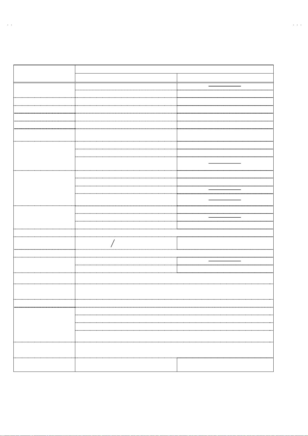
SPECIFICATIONS
Item
Dimensions ( W
Mass
TV RF System
Colour System
Stereo System
Teletext System
Receiving Frequency
Intermediate Frequency
Colour Sub Carrier Freq.
Power Input
Power Consumption
Aerial Input Term
Picture Tube
High Voltage
Speaker
Audio Output
EXT-1/EXT-2/EXT-3 (IN/OUT)
EXT-4 (Input)
××××H××××
D )
Content
AV32X1 0EUS / AV28X10EUS AV28X1 0EK S / AV 28 X10EIS
(32”) : 85.5cm×55.0cm×56.8cm
(28”) : 78.0cm×50.9cm×49.9cm 78.0cm×50.9cm×49.9cm
(32”) : 54.2kg / (28”) : 40.2kg 40.2kg
CCIR ( B/G, D/K, L, L’,I) CCIR ( I )
PAL / SECAM / NTSC (Only in EXT mode) PAL / NTSC (Only in EXT mode)
A2 (B/G, D/K) / NICAM (B/G, I, D/K, L) NICAM ( I )
Fastext (UK system) / TOP (German system)
WST(world standard system)
: 47MHz ~ 470MHz
VHF
: 470MHz ~ 862MHz
UHF
French cable TV channel of broadcast frequencies
!
116~172MHz & 220~469MHz
Carri er : 38.9MHz(B/G, D/K , I, L ) / 33.95MHz (L’)
VIF
Carrier : 33.4MHz(5.5MHz : B/G)
SIF
32.9MHz (6.0MH z : I )
32.4MHz(6.5MHz : L, D/K)
40.45MHz (6.5MHz : L’)
: 4.43MHz
PAL
: 4.40625MHz / 4.25MHz
SECAM
: 3.58MHz / 4.43MHz
NTSC
AC 220V~240V , 50Hz
189W(Max)
(32")
140W(Avg)
75Ωunbalanced, Coaxial
(32”) : Viewable area 76cm ( measured diagonally)
(28”) : Viewable area 66cm ( measured diagonally) Viewable area 66cm ( measured diagonally)
+
31.0kV (at zero beam current)
16cm×4cm, Oval type×2
7.5W + 7.5W
21-pin Euro connector (SCART socket)×3
Video
Audio(L/R)
S / Video
1.0kV
-1.5kV
: Vp-p 75Ω(RCA pin j ac k)
: 500mVrms(-4dBs), High Impedance (RCA pin jack)
Y : 1Vp-p POSITIVE (Negative sync Provided, when terminated with 75Ω)
C : 0.3Vp-p (Burst signal, when terminated with 75Ω)
(28”)
183W(Max)
127W(Avg)
Fastext (UK system)
WST(world standard system)
: 47MHz ~ 470MHz ( EI model )
VHF
: 470MHz ~ 862MHz ( EK / EI model )
UHF
Carrier : 38.9MHz
VIF
Carrier : 32.9MHz (6.0MHz )
SIF
: 4.43MHz
PAL
: 3.58MHz / 4.43MHz
NTSC
183W ( Max) , 127W( Avg)
AUDIO OUT (Variable)
Headphone jack
Remote Control Unit
0~1Vrms, Low Impedance (R CA pin jack×2)
Stereo mini jack (φ3.5mm )
RM-C54 (AAA/R03 dry cell battery×2) RM -C55 (AAA/R03 dry cell battery×2)
Design & specifications are subject to change without notice
2
.
No.51780
Page 3
A
A
A
A
■■■■
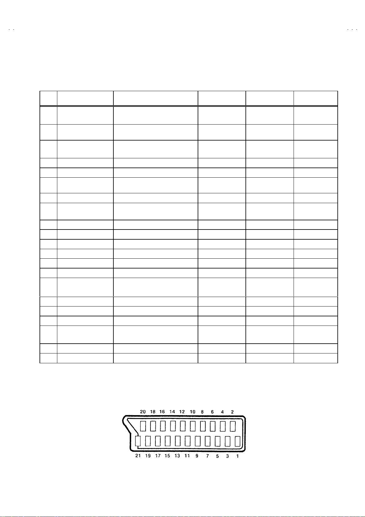
21-pin Euro connector (SCART socket) : EXT-1 / EXT-2 / EXT-3
(P-P= Peak to Peak, B -W= Bl ank ing to white peak)
V32X10EUS
V28X10EUS
V28X10EKS
V28X10EIS
Pin
No.
Signal Designation Matching Value EXT-1 EXT-2 EXT-3
1 AUDIO R output 500mVrms(Nominal),
Low impedance
2 AUDIO R input 500mVrms(Nominal),
High impedance
3 AUDIO L output 500mVrms(Nominal),
Low impedance
4 AUDIO GND
5 GND (B)
6 AUDIO L input 500mVrms(Nominal),
High impedance
7B input
8 FUNCTON SW
(SLOW SW)
9 GND (G)
10 SCL3 NC
11 G input
12 SDA3 NC
13 GND (R)
14 GND (YS)
15 R / C input
16 Ys input
17 GND(VIDEO output)
18 GND(VIDEO input)
19 VIDEO out pu t
20 VIDEO / Y input
21 COMMON GND
700mV
Low : 0-3V, High : 8-12V, High
impedance
700mV
R : 700mV
C : 300mV
Low : 0 - 0.4, High : 1 - 3V, 75
1V
1V
, 75
Ω○○
B-W
, 75
Ω○○
B-W
, 75
Ω
B-W
, 75
Ω
P-P
(Neg ati ve g oin g s ync ) , 75
P-P
(Neg ati ve g oin g s ync ) , 75
P-P
Ω○ ○
Ω○
Ω○ ○ ○
(TV OUT)
(TV OUT)
(only R)
(TV)
○
○○○
○
○○○
○○○
○○○
○○○
○○○
○○○
○○
○
○○○
○○○
○○○
○
(LINE OUT)
○
(LINE OUT)
○
○
○○
○
(LINE OUT)
NC
NC
NC
NC
NC
NC
NC
(only C)
NC
NC
Pin assignment
[
]
No.51780
3
Page 4
A
V32X10EUS
A
V28X10EUS
SAFETY PRECAUTIONS
AV32X10EUS / AV28X10EUS
1. The design of this product contains special hardware, many
circuits and components specially for safety purposes. For
continued protection, no changes should be made to the original
design unless authorized in writing by the manufacturer.
Replacement parts must be identical to those used in the original
circuits. Service should be performed by qualified personnel
only.
2. Alterations of the design or circuitry of the products should not be
made. Any design alterations or additions will void the
manuf act urer's warr an t y and wil l fur t h er reli ev e t h e manufacturer
of responsi bility f or person al injury or pr operty dam age res ulting
therefrom.
3. Many electrical and mechanical parts in the products have
special safety-related characteristics. These char acteristics are
often not evident f rom visual i nspection nor can t he protect ion
afford ed by them n ecess arily be obt ained by using rep lacem ent
compon ents rated f or higher voltag e, watt ag e, etc. R epl acem ent
parts which have these special safety characteristics are
identified in the parts list of Service manual.
compon ents hav in g su ch feat ures are id entif ied by s hadin g
on the sche matics and by (
manual.
have the same safety characteristics as the recommended
replac ement part shown i n the p arts list of S ervic e manu al may
cause shock, fire, or other hazards.
The us e of a subst itute replacement which does n ot
) on the parts list in Service
!!!!
Electrical
4.
Don't short b etween the LIV E side groun d and ISOLATED
(NEUTRAL) side ground or EARTH side ground when
repairing.
Some model's power circuit is partly different in the GND. The
difference of the GN D is sh ow n b y t h e LI V E : (") side GND, the
ISOLATED(NEUTRAL ) : (#) side GND and EARTH : ($) side
GND. Don't short between the LIVE side GND and
ISOLATED(NEUTRAL) side GND or EARTH side GND and
never meas ure with a measuri ng apparatus (osc illoscope etc .)
the LIVE side GND and ISOLATED(NEUTRAL) side GND or
EARTH side GND at the same time.
If above not e wi ll n ot be kept, a fuse or any parts w ill be br oken.
5. If any repair has been made to the chassis, it is recommended
that the B1 setting should be checked or adjusted (See
ADJUSTMENT OF B1 POWER SUPPLY).
6. The hig h voltage app lied t o the picture t ube must c onform wit h
that specified in Service manual. Excessive high voltage can
cause an increase in X-Ray emission, arcing and possible
component damage, therefore operation under excessive high
voltag e conditions s hould b e kept to a mi nimum, or sh ould be
prevented. If severe arcing occurs, remove the AC power
immediately and determine the cause by visual inspection
(incorrect install ation, crack ed or melted high volt age harness,
poor solderi ng, etc.). To maintain the pr oper minimum level of
soft X-Ray emission, components in the high voltage circuitry
including the picture tube must be the exact replacements or
alternatives approved by the manufacturer of the complete
product.
7. Do not check high voltage by drawing an arc. Use a high voltage
meter or a high voltage probe with a VTVM. Discharge the
pictur e tube bef ore attempting met er connect ion, by connecting
a clip l ead to th e g roun d fr am e and c on necti ng t h e oth er end of
the lead through a 10k" 2W resistor t o the an ode button .
8. W hen servic e is requir ed, obser ve the origin al lead dress . Extr a
precaut ion shou ld be gi ven to assure c orrect l ead dr ess in t he
high voltage circuit area. Where a short circuit has occurred,
those comp onents that in dicat e evidenc e of over heating should
be replaced. Always use the manufacturer's replacement
components.
9.
Isolation Check
(Saf ety for Electrical Shock Hazard)
After re-assembling the product, always perform an isolation
check on the exposed metal parts of the cabinet (antenna
termin als , vid eo/ au dio input and output term inals, Con trol knobs,
metal c abinet, s crewhead s, earph one j ack, contr ol shafts, etc.)
to be sure the product is safe to operate without danger of
electrical shock.
(1)
Dielectric Stren gt h Test
The isol ation b etween th e AC pr imar y circuit and all metal parts
expos ed t o th e user, p ar tic u larly any exp osed metal part h avi ng a
return p ath to the chassis should withst and a voltage of 3000V
AC (r.m.s .) for a period of on e s ec on d.
(. . . . W ithstand a voltag e of 1100 V AC ( r.m.s.) to an applianc e
rated up t o 120V, and 3000 V AC (r. m.s.) t o an appl iance r ated
200V or mor e, f or a peri od of on e s ec on d.)
This method of test requires a test equipment not generally found
in the service trade.
(2)
Leak age Current Check
Plug the AC lin e c or d dir ec t l y int o t he AC outlet ( d o not use a line
isolation transformer during this check.). Using a "Leakage
Current Tester", measure the leakage current from each exposed
metal part of the cabinet, particularly any exposed metal part
having a return path to the chassis, to a known good earth
ground ( water pipe, etc. ). An y leak age c urr ent mus t not exceed
0.5mA AC (r.m.s.).
However, in tropical area, this must not exceed 0.2mA AC
(r.m.s.).
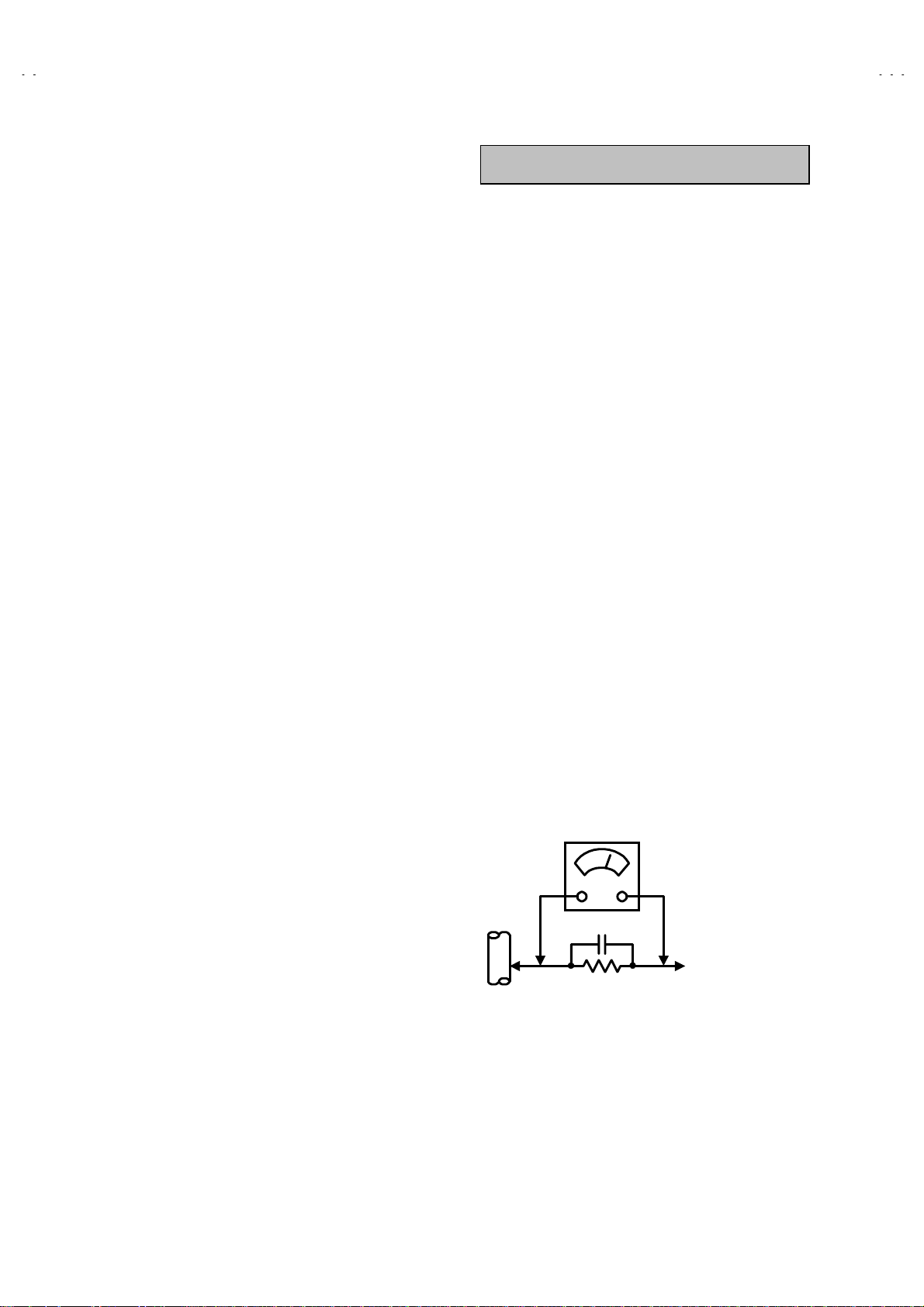
Alternate Check Method
""""
Plug the AC lin e c or d dir ec t l y int o t he AC outlet ( d o not use a line
isolati on transform er during t his check. ). Use an AC voltmet er
having 1000 ohms per volt or more sensitivity in the following
manner. Connect a 1 500" 10W resistor paralleled by a 0.15#F
AC-typ e capacitor betw een an expos ed metal part and a know n
good earth ground (water pipe, etc.). Measure the AC voltage
across the resistor with the AC voltmeter. Move the resistor
connect ion t o each exp os ed met al p art, part icul arl y any exp osed
metal part h avin g a return p ath to th e chassis , and meas ure th e
AC voltag e across the res istor. N ow, re vers e the plug in the AC
outlet and repeat each measurement. Any voltage measured
must not exceed 0.75V AC (r.m.s.). This corresponds to 0.5mA
AC (r.m.s.).
However , i n t ropical area, this m us t not exc eed 0.3V AC ( r . m.s . ).
This corresponds to 0.2mA AC (r.m.s.).
0.15μF AC-TYPE
1500
GOOD EARTH GROUND
"
AC VOLTMETER
(HAVING 1000
OR MORE SENSITIVITY)
10W
"
/V,
PLACE THIS PROBE
ON EACH EXPOSED
METAL PART
4
No.51780
Page 5

A
V28X10EKS
A
V28X10EIS
SAFETY PRECAUTIONS
1. T he design of this produc t cont ains speci al hard ware and m any
circuits and components specially for safety purposes. For
continued protection, no changes should be made to the original
design unless authorized in writing by the manufacturer.
Replacement parts must be identical to those used in the original
circuits. Service should be performed by qualified personnel
only.
2. Alterations of the desi g n or c ir c ui try of th e product s h ould not be
made. Any design alterations or additions will void the
manuf act urer's warr an t y and wil l fur t h er reli ev e t h e manufacturer
of responsi bility f or person al injury or pr operty dam age res ulting
therefrom.
3. Many electrical and mechanical parts in the product have special
safety-related characteristics. These characteristics are often not
evident from visu al ins pec tion n or can th e protect i on aff orded by
them nec essar y be obtain ed by usi ng repl acemen t comp onent s
rated for hi gher volt age, wattag e, etc. R eplacem ent parts whic h
4. The leads in the products are routed and dressed with ties,
AV2 8X10E KS / AV28X10EIS
have these special safety characteristics are identified in the
Parts List of S er vice Man u al. E l ec tr ical comp on en ts having s uch
features ar e i d entified by shad in g on the sc h em ati c s an d b y (!)
on the P arts Lis t in th e Ser vic e Man ual. Th e us e of a subst itu te
replacement which does not have the same safety
charact erist ics as the rec omm ended r eplacem ent par t shown in
the Par ts L i s t of Service Manual may c ause shoc k, fire, or oth er
hazards.
clamps, tubing’s , bar riers and the like to b e separ ated fr om li ve
parts, high temperature parts, moving parts and / or sharp edges
for the prevention of electric shock and fire hazard. When
servic e is r eq uired, t h e original l ead routi ng and dress sh ou ld b e
observed, and it should be confirmed that they have been
return ed t o nor m al , after re-assembli ng.
WARNING
1. The equipment has been designed and manufactured to meet international safety standards.
2. It is the legal responsibility of the repairer to ensure that these safety standards are maintained.
3. Repairs must be made in accordance with the relevant safety standards.
4. It is essential that safety critical components are replaced by approved parts.
5. If mains voltage selector is provided, check setting for local voltage.
No.51780
5
Page 6
A
V32X10EUS
A
A
A
V28X10EUS
V28X10EKS
V28X10EIS
FEATURES
New chassis design enable use of an interactive on screen
"
control.
The TELETEXT SYSTE M has a built-i n FAST EXT ( UK s ystem),
"
TOP (German system) and WST (world standard system)
system.
Pure FLAT CRT reproduce fine textured.
"
Digi Pure pro : Auto digi pure with motion picture compensation.
"
B ecause this TV uni t corresp onds t o multipl ex broadc ast, us ers
"
can enjo y music pr ograms an d spor ting ev ents wit h live real ism.
In additi on, BILINGUAL programs c an be heard in their original
language.
Built-in ECO (ECONOMY, ECOLOGY) MODE.
"
In accordance with the brightness in a room, the brightness
and/or contrast of the picture can be adjusted automatic ally to
make th e opti mu m pictur e whic h is eas y on t h e ey e.
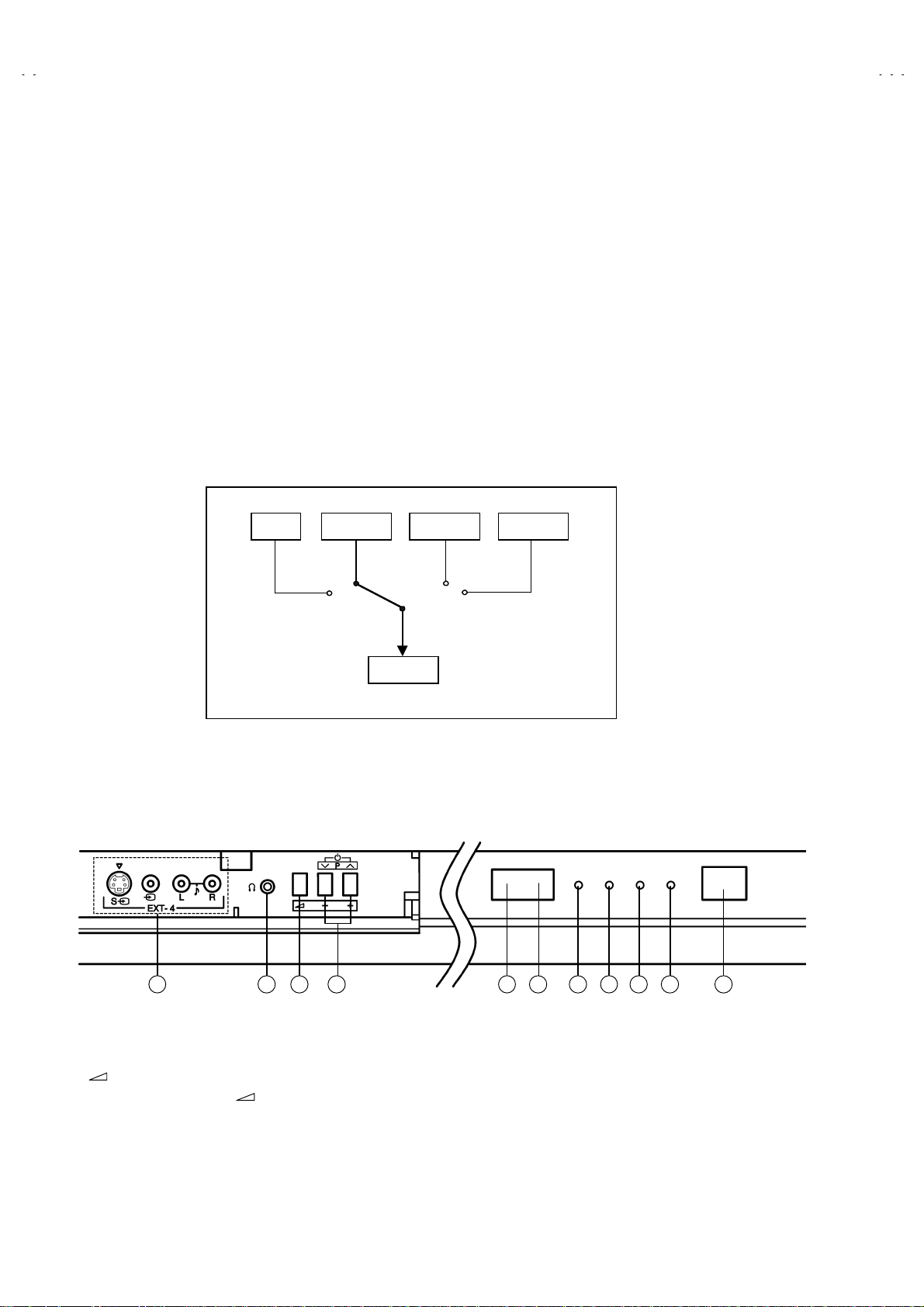
TV EXT-1 EXT-3
Users can make VCR dubbing of picture and sound by controlling
"
the AV select or to sel ect an opti onal sour ce at the E XT-2 output
shown in figure.
EXT-4
FUNCTIONS
(FRONT)
1 42 5 6 7 8 9 10 113
EXT-4 (INPUT) terminals
①
Headphone jack (mini jack)
②
(Volume) button
③
Function (P∨/∧ buttons / -/+ buttons )
④
EXT-2
Remote control sensor
⑤
ECO sensor
⑥
Hyper Sound lamp
⑦
ECO lamp
⑧
Sleep tim er lam p
⑨
Power lamp
⑩
Main power button
⑪
6
No. 51780
Page 7
A
V32X10EUS
A
A
A
V28X10EUS
V28X10EKS
V28X10EIS
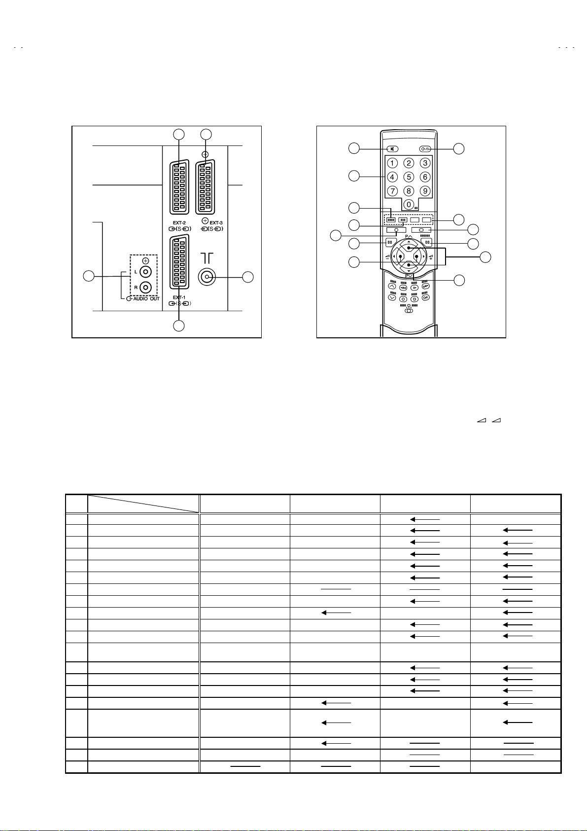
(REAR PANEL) (REMOTE CONTROL UNIT )
32
5
1
EXT-1(IN/OUT) Terminal
①
EXT-2(IN/OUT) Terminal
②
EXT-3(IN/OUT) Terminal
③
Aerial Socket
④
Audio out put termin al
⑤
4
1
2
3
4
5
6
7
Muting K e y
①
Number Key
②
ZOOM Key
③
Hyper Sound Key
④
Information Key
⑤
TV Key
⑥
Volume -/+ Key
⑦
8
9
13
Standby (power) Key
⑧
Colour K ey
⑨
TEX T Key
⑩
K/MENU Key
⑪
PR Channel ∨/∧Key
⑫
FUNCTION ( / / P∧/ P∨) Key
⑬
10
11
12
+ -
MAIN DIFFERENCE LIST
!!!!
MAIN PWB SMF-1006A-U2 SMF-1007A-U2 SMF-1903A-U2
POWER & DEF. PWB SMF-2002A-U2 SNF-2003A-U2
FRONT CONTROL PWB SMF-8006A-U2 SMF-8004A-U2
CRT SOCKET PWB SMF-3003A-U2 SMF-3004A-U2
PICTURE TUBE (V01) W76ERF041X044 W66QDE891XA25
!
DEG COIL (L01) QQW0066-001 QQW0101-001
!
ROTATION COIL (L03) CELD904-001
!
FBT (SERVICE) QQH0091-002-I2 QQH0091-003-I2
!
POWER CORD QMPK160-185-JC QMPN130-185-JC
!
FRONT CABINET ASS’Y LC10376-012A-U LC10662-009B-U
!
REAR COVER LC10378-004A-U LC10664-003A-U
!
RATING LABEL
!
PACKING CASE AM1002-070-E AEM1002-A68-E
CUSHION ASS’Y LC10384-002C-U LC10722-002A-U
EURO LABEL AEM1039-090-E AEM1039-091-E
REMOTE CONTROL UNIT RM-C54-1C RM-C55-1C
INST BOOK
!
S. DIAGRAM 2832X10EUS-HSAE
X-RAY CARD AEM1059-001A-E AEM1057-001A-E
REG. SHEET AEM3148-001-E
Model name
AV32X10EUS AV 28X10EUS AV28X10EIS AV28X10EKS
LC20380-010A-U
LC20079-010A-U
LCT0887-001A-U
LCT0888-001A-U
LCT0889-001A-U
LC20380-009A-U
LC20379-009A-U
LC20080-013A-U LC20091-021A-U
LCT0893-001A-U
No. 51780
7
Page 8
A
V32X10EUS
A
A
A
A
V28X10EUS
V28X10EKS
V28X10EIS
SPECIFIC SERVICE INSTRUCTIONS
DISASSEMBLY PROCEDURE
REMOVING THE REAR COVER
1. Unplug the power cord.
2.
[32inch]
Remove the 13 screws marked
[28inch]
Remove the 12 screws marked
3. Withdraw the rear cover toward you.
as shown in the Fig. 1.
!!!!
as shown in the Fig. 1.
!!!!
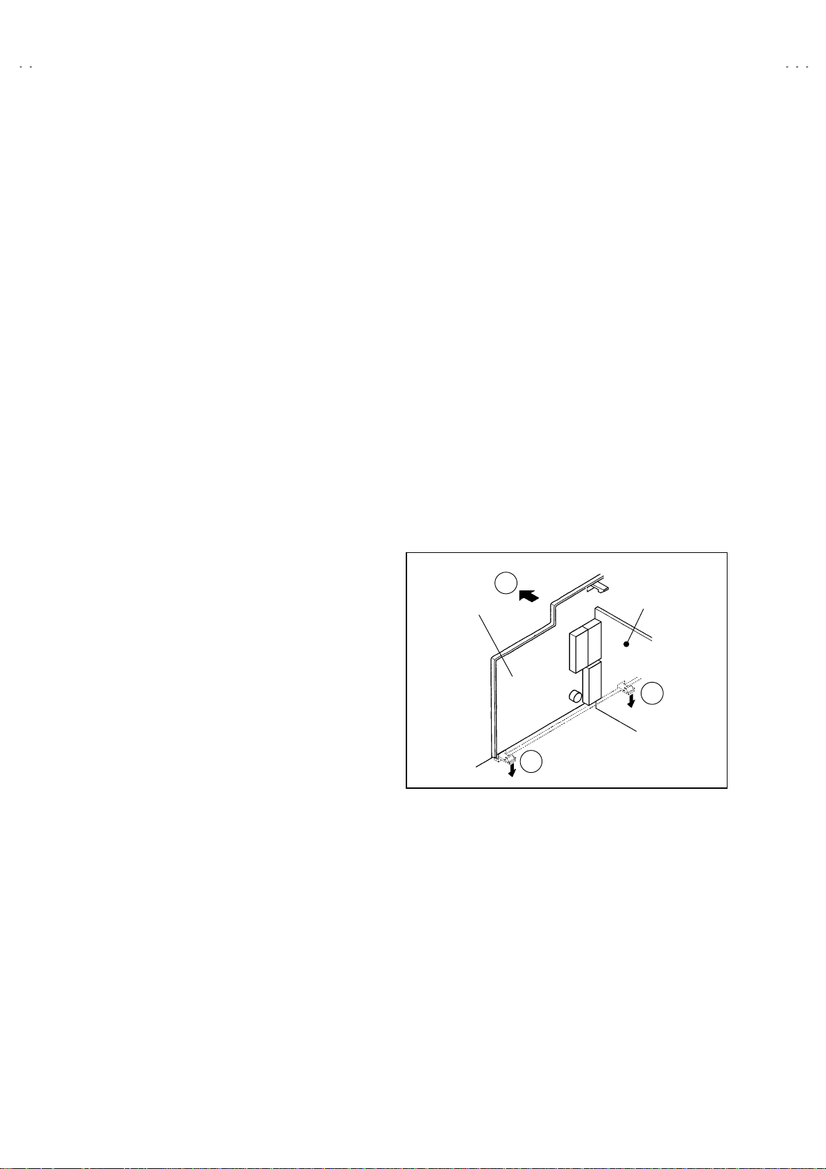
REMOVING THE AV TERMINAL BOARD
After removing the rear cover.
"
1. Remove the 3 screws marked
2. Remove the 2 c laws m ark ed
in Fig. 2.
3. Remove th e AV TERMIN AL BOARD slig htly in the direc tion of
arrow
as shown in Fig. 2.
$$$$
as shown in the Fig. 1.
""""
under the CHASSIS as shown
####
REMOVING THE CHASSIS
After removing the rear cover.
"
1. Slightl y rais e th e bot h sid es of th e ch assis b y h an d and rem ove
the 2 claws under the both sides of the chassis from the front
cabinet.
2. Withdraw the chassis backward.
(If necessary, take off the wire clamp , connectors etc.)
CHECKING THE PW BOARD
To check the back side of the PW Board.
1) Pull out the chassis. (Refer to REMOVING THE CHASSIS).
2) Erect t he ch assis vertic ally s o that you c an easi ly ch eck th e
back side of the PW Board.
[CAUTION]
When erecting the chassis, be careful so that there will be no
"
co n tac ting w i th oth er PW Board.
Before turning on power, make sure that the wire connector is
"
properly connected.
When conducting a check with power supplied, be sure to confirm
"
that the CRT EARTH WIRE (BRAID ED ASS’Y) is conn ected to
the CRT SOCKET PW board.
WIRE CLAMPING AND CABLE TYING
1. Be sure to clamp the wire.
2. Never remove the cable tie used for tying the wires together.
Should it be inad ver tent l y remov ed, b e sur e to ti e th e wir es with
a new cable tie.
F
V TERMINAL
BOARD
AV SW PWB
REMOVING THE SPEAKER
After removing the rear cover.
"
1. Remove the 2 screws marked
: When removing the screws marked
NOTE
remove the lower side screw first, and then remove the
upper one.
2. Remove the 2 screws
3. Follow the same steps when removing the other hand speaker.
&&&&
as shown in Fig. 1.
%%%%
%%%%
attaching the speaker.
of the speaker
E
E
Fig. 2
8
No.51780
Page 9
A
A
A
A
A
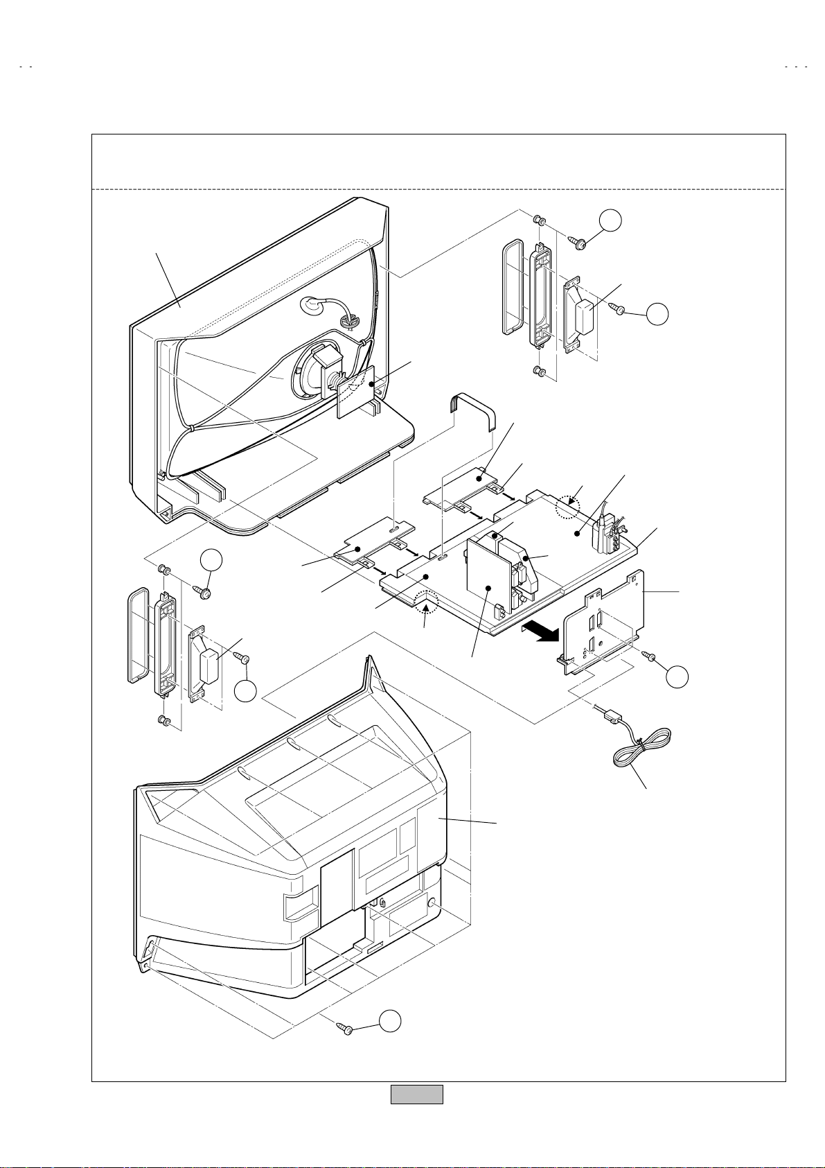
This exploded view describes about the AV32X10EUS (32inch).
*
Although the 28inc h is slig htly differ en t f r om t his figure, you can use the e xp loded view for disassemb li ng the 28inch
in the same step as for this one.
D
FRONT CABINET
SPEAKER
C
CRT
SOCKET
PWB
FRONT
CONTROL
PWB (L)
V32X10EUS
V28X10EUS
V28X10EKS
V28X10EIS
D
FRONT
CONTROL
PWB (R)
SPEAKER
C
CONTROL
BASE
MAIN PWB
CLAW
V SW PWB
REAR COVER
CONTROL
BASE
MICON
PWB
100Hz
PWB
POWER & DEF
PWB
CLAW
CHASSIS
AV TERMINAL
BOARD
B
(×3)
POWER CORD
(×13)
A
Fig.
1
No.51780
9
Page 10
A
V32X10EUS
A
A
A
A
A
A
A
A
V28X10EUS
V28X10EKS
V28X10EIS
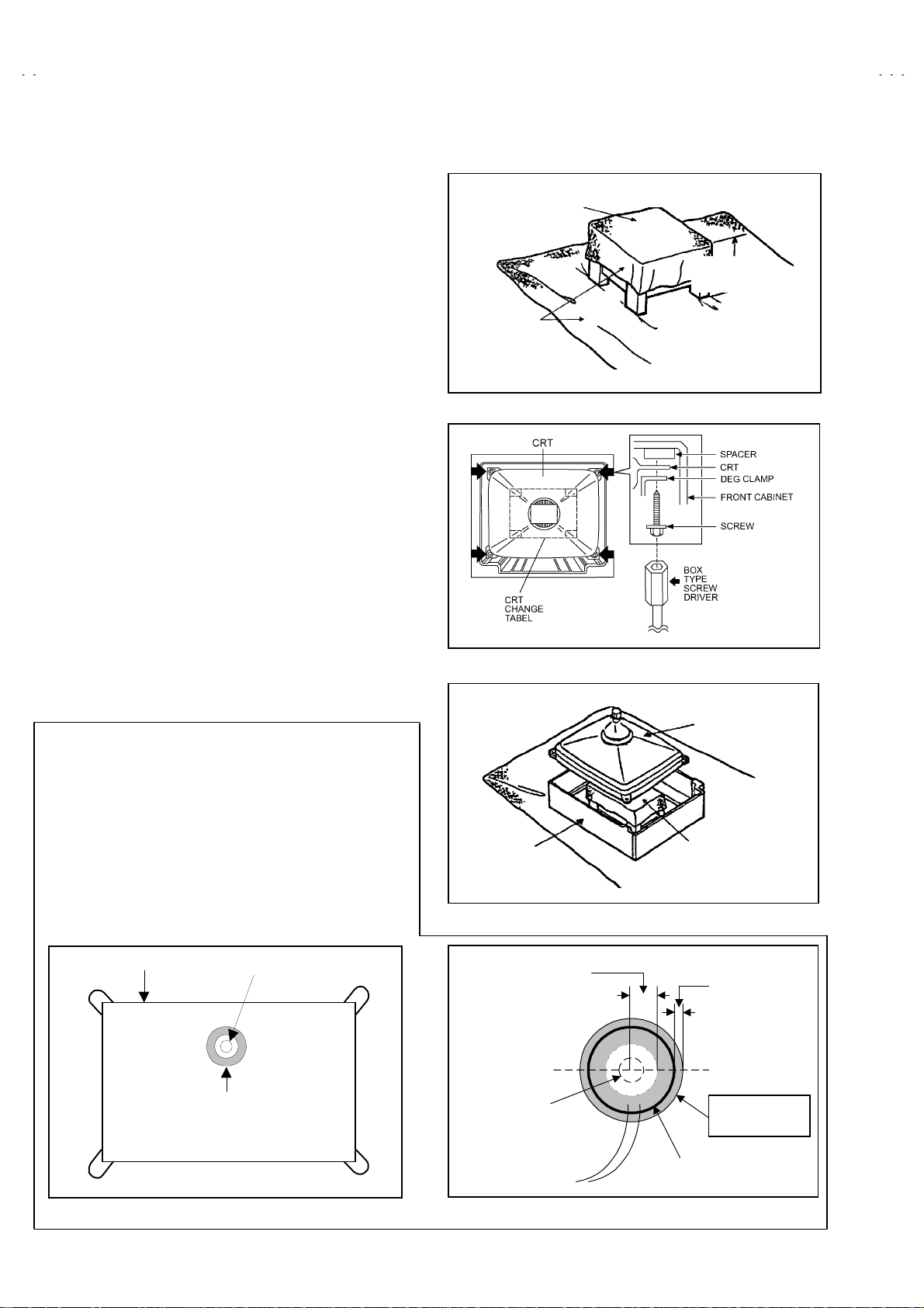
REMOVING THE CRT
Replacement of the CRT should be performed by 2 or more
$
persons.
After removing the cover, chassis etc.,
!
1. Putting the CRT change table on soft cloth, the CRT change table
should also be covered with such soft cloth (shown in Fig.3).
2. While keeping the surface of CRT down, mount the TV set on the
CRT change table balanced will as shown in Fig.4.
3. Remove 4 scr ews m ar k ed b y arrows with a b ox type scr ew driver
as shown in Fig.4.
Since the cabinet will dr op w h en s c rews h av e b een removed , be
!
sure to support the cabinet with hands.
4. After 4 sc rews have been removed, put the cabinet s lowly on
cloth (At this time, be carefully so as not to damage the front
surface of the cabinet) shown in Fig.5.
The CRT should be assembled according to the opposite
!
sequence of its dism oun t i ng st eps .
T he CRT ch ang e t ab l e shoul d preferab l y be smal l er th at th e CRT
$
surfac e, and its height be about 35c m. (Fig.3)
About CRT Spacer (Fig.4)
$
An appropriat e CR T s pacer sh ould b e used in th e corr es p on di ng
CRT in accordance with the type o f th e CRT.
When a CRT is repl ac ed, s peci al att enti on s houl d be p aid to t his
matter.
CRT CHANGE TABLE
PPROX.
35cm
CLOTH
Fig. 3
COAT ING OF SILICON GREASE FO R ELECTRICAL
INSULATION ON THE CRT ANODE CAP SECTION.
Subs equent t o repl acement of the CRT and HV tr ansf ormer or
!
repair of the anode c ap, etc. by dismounting them, be sure to
coat silicon grease for electrical insulation as sh ow n in Fi g.6.
Wipe around the anode button with clean and dry cloth. (Fig.6)
Coat sil icon gr eas e on t he s ection arou nd the anod e but ton. A t
this ti me, t ak e c are s o th at an y si lic on gr eas es d os e not s tic k to
the anode button. (Fig.7)
Silicon grease product No. KS - 650N
★★★★
CRT
Silicon gr ease
node button
coating
CABINET
pprox.
20mm (Do not
coat grease on
this section
node button
(No sticking of
silicon grease)
Fig. 4
CRT
CRT
CHANGE TABLE
Fig. 5
Silicon gr ease
should b e c oat ed
by 5mm or mor e
from the outside
diamet er of
anode cap.
Coating position
of silicon grease
node cap
Fig. 6 Fig. 7
10
No. 51780
Page 11

A
A
A
A
REPLACEMENT OF MEMORY ICs
1. Memory ICs
This TV use mem ory ICs . In the mem or y ICs, there ar e memor iz ed dat a
for cor rectl y op er ating th e vi deo an d def l ection cir cu its. W h en r epl acing
memory ICs, be sure to use ICs written with the initial values of data.
2. Procedu re for repl acin g memory ICs
PROCEDURE
(1)
Power off
Switch th e p ow er off and unplug th e p ow er c ord f r om t h e wall outlet.
SERVICE MENU
1. IF 2. V/C
3. AUDIO 4. DE F
5. VSM PRESET 6. STATUS
7. PI P 8. - - -
9. SHIPPING (OFF) 0. BUS FREE
1-9 : SELECT : EXITi
Fig.1
V32X10EUS
V28X10EUS
V28X10EKS
V28X10EIS
(2)
Replace ICs
.
Be sure to use memory ICs written with the initial data values.
(3)
Power on
Plug the power cord into the wall outlet and switch the power on.
(4)
Check and set SYSTEM CONSTANT SET:
It must not adjust with ou t sign al.
****
1) Press the INFORMATION key and the MUTING key of the
REMOTE CONTROL UNIT simultaneously.
2) T he SERVICE MENU scr een of Fi g . 1 wil l b e dis pl ay ed.
3) While the SERVICE MENU is displayed, press the
INFORM ATION key and MUT ING key s imultan eousl y, and th e
SYSTEM CONSTANT SET screen of Fig. 2 will b e dis pl ay ed .
4) Ch eck t he s etti ng valu es of th e SY STE M CON STA NT S ET of
Table 1. If the valu e is dif f erent , s elect the s et ting item wi th th e
FUNCTION UP/DOWN key, and set th e correct value with the
FUNCTION -/+ key.
5) Press the MENU(OK) key to memorize the setting value.
6) Press the INFORMATION key, and return to the normal screen.
(5)
Setting o f re ce iv e channel s
Set the receive channel.
For setting, refer to the OPERATING INSTRUCTIONS.
SYSTEM CONSTANT SET
1. DESTINATION
OK
+ : STORE : EX IT
**
i
Fig.2
2. CRT TYPE 1 6 : 9
3. PURITY NO
4. PICTURE TILT YES
5. DIGIPURE PRO YES
6. PIP NO
7. PIC & TEXT YES
8. DOLBY NO
9. BBE YES
10. PROGRESSIVE YES
11. TDA9178 YES
12. TONE IC NO
13. FLAT YES
NAME OF REMOTE CONTROL KEY
Names of key
INFORMATION
key
iiii
(6)
Setting of SERVICE MENU
Verif y the s etting items of t h e
SERVICE MENU
of Table 2, and reset
wh ere nec essar y .
For setting, refer to the SERVICE ADJUSTMENTS.
(7)
User setti n gs
Check th e us er s ett in g values of Table 3, and if set ti ng v al u e is
MUTING
MENU
FUNCTION UP/DOWN
OK
▼
▼
different, set the correct value.
For setting, refer to the OPERATING INSTRUCTIONS.
FUNCTION -/+
TV
No. 51780
▼
▼
+
TV
11
Page 12

A
V32X10EUS
A
A
A
US
V28X10EUS
V28X10EKS
V28X10EIS
SETTING VALUES OF SYSTEM CONSTANT SET (TABLE 1 )
Setting item Setting content
1. DESTINATION EU EI EK
EK EU EI
AV32X10E
AV28X10EUS
Setting value
AV28X10EIS AV28X10EKS
1 TUNER
16 : 9 4 : 3
YES NO
YES NO
YES NO
2 TUNER
YES NO
YES NO
YES NO
YES NO
YES NO
YES NO
YES NO
NO
2. CRT TY P E 16 : 9
3. PURITY NO
4. PICTURE TILT YES
5. DIGIPURE PRO YES
6. PIP NO
7. PIC & TEXT YES
8. DOLBY NO
9. BBE YES
10. PROGRESSIVE YES
11. TDA9178 YES
12. TONE IC NO
13. FLAT YES
SERVICE MENU SETTING ITEMS (TABLE 2)
Setting item Setting value Setting item Setting value
1. IF 1. VCO 4. DEF. 1. V-SHIFT
2. V-SIZE
3. H-CENT
4. H-SIZE
5. TRAPEZ
2. V / C 1. RGB BLK
2. WDR R
3. WDR G
4. WDR B
5. BRIGHT
6. CONTRAST
7. COLOUR
8. HUE
9. SHARP
10. VCO ADJUSTMENT
11. VIDEO AGC
12. SYNC SLICE
5. VSM PRESET
COOL
NORMAL
WARM
6. EW-PIN
7. COR-PIN
8. COR-UP
9. COR-LO
10. ANGLE
11. BOW
12. V-S.CR
13. V.LIN
1. CONT.
2. BRIGHT
3. SHARP
4. COLOUR
5. HUE
6. WDR R
7. WDR G
8. WDR B
3. AUDIO
(Do not adjust)
12
1. ERR LIMIT
2. A2 ID THR
6. STATUS
No. 51780
(Do not adjust)
VPS
PDC
Page 13

A
A
A
A
USER SETTING VALUES (TABLE 3)
Setting item Setting value Setting item Setting value
SUB POWER ON VOLUME Appropriate sound volume
SHIPPING CHANNEL PR1 DISPLAY INDICATED
V32X10EUS
V28X10EUS
V28X10EKS
V28X10EIS
PRESET CHANNEL
PICTURE SETTING EXT SETTING
TINT
CONTRAST
BRIGHT
SHARP
COLOUR
ECO MODE
PICTURE FEATURES FEATURES
DIGITAL VNR
DIGIPURE PRO
COLOUR SYSTEM
4:3 AUTO ASPECT
SOUND SETTING INSTALL
BASS
TREBLE
BALANCE
TV SPEAKER
HYPER SOUND
BBE
See ; OPERATING
INSTRUCTIONS.
COOL
REFER to VSM SETTING
REFER to VSM SETTING
REFER to VSM SETTING
REFER to VSM SETTING
OFF
AUTO
AUTO
TV : According to preset CH
EXT : AUTO
PANORAMIC
CENTER
CENTER
CENTER
L / R
OFF
ON
ZOOM MODE PANORAMIC
ID
DUBBING
SLEEP TIMER
BLUE BLACK
CHILD LOCK
DECODER (EXT-2)
LANGUAGE
EDIT
BLANK
EXT-1→EXT-2
OFF
ON
ID : No.0000, ALL CH : OFF
ALL CH : OFF
ENGLISH
PR CHANNEL ONLY
OTHERS : BLANK
No. 51780
13
Page 14

A
V32X10EUS
A
A
A
V28X10EUS
V28X10EKS
V28X10EIS
SERVICE ADJUSTMENTS
BEFORE STARTING SERVICE ADJUSTMENT
1.
There are 2 ways of adjusting this TV: One is with the
REMOTE CONTRO L UNIT and t he oth er is t he conv ention al
method using adjustment parts a nd components.
2.
The setting (adjustment) using the REMOTE CONTROL
UNIT is ma de on t he b asis of th e initi al se tting v alue s. The
setting values which adjust the screen to the optimum
condition can be different from the initial setting values.
3. Make sure that connection is correctly made to AC power
source.
4. Turn on the power of the TV and measuring instrument for
warming up for at least 30 minutes before starting adjustment.
5. If the receive or input signal is not specified, use the most
appropriate signal for adjustment.
6. N ever touc h parts ( suc h as vari able r esist ors, tr ansf ormers and
condens ers) not show n in the adj ustment i tems of this s ervice
adjustment.
7. Preparation for adjustment (presetting):
Unless oth erwise sp ecified in t he adjust ment items , preset t he
following functions with the REMOTE CONTROL UNIT:
Setting position
"
PICTURE MODE (VSM) NORMAL
SLEEP TIMER OFF
BALANCE CENTER
ECO OFF
ZOOM PANORAMIC
MEASURING INSTRUMENT AND FIXTURES
1. DC voltmeter (or digital voltmeter)
2. Oscilloscope
3. Signal generator (Pattern generator) [PAL / SECAM / NTSC]
4. Remote control unit
ADJUSTMENT ITEMS
Checking items.
●
Adjustment of FOCUS.
●
VSM preset s etti ng.
●
VIDEO / CHROMA circuit adjustment.
●
DEFLECTION circuit adjustment.
●
AUDIO circuit adjustment.
●
(Do not adjust)
14
No. 51780
Page 15

A
A
A
A
ADJUSTMENT LOCATIONS
(
)
)
)
)
(L)
(R)
V32X10EUS
V28X10EUS
V28X10EKS
V28X10EIS
FRONT
FRONT
FRONT CONTROL PWB (R
POWER
SW
FUSE
PW
POWER
TIMER
ECO
W
HYPER
SOUND
MAIN PWB POWER&DEF P WB
CN002 W DEG
L
MICON PWB
AV SW PWB
CN007
CN001
TUNER
CDS
CN002
FRONT CONTROL PWB (L
MENU
HEAD
PHONE
F
J
CN004
CN005
DOWN
UP
CH
CH
J
VIDEO
EXT- 4
S-IN
FRONT
AUDIO
OUT(L/R)
EXT 1 2 3
IN-OUT IN
TOP
CN003
CN013
100Hz PWB
ANT-IN
CRT SOCKET PWB
TP-47R
TP-47G
TP-E
CN013
CRT
C2
SOLDER SIDE
E1
TP-47B
CN014
CN006
VM
VM
CN014
HV
HVT
FOCUS 1 VR
FOCUS 2 VR
SCREEN VR
X
1
5
1pin:B1(TP-91
2pin:NC
3pin:X-RAY
4pin:X-RAY
5pin:GND
No. 51780
15
Page 16

A
V32X10EUS
A
A
A
V28X10EUS
V28X10EKS
V28X10EIS
BASIC OPERATION SERVICE MENU
1. TOOL OF SERVICE MENU OPER AT ION
Operate the SERVICE MENU with the REMOTE CONTROL UNIT.
2. SERVICE MENU ITEMS
With the S ERVIC E MENU, vari ous s ettings (adjust ments ) can be made, and the y are br oadly c lassif ied in th e f ollowing items of settings
(adjustments):
(1)
(2)
(3)
(4)
1. IF
・・・・・・・・・・・・・・・・・・・・・・・
2.V/C
・・・・・・・・・・・・・・・・・・・・・・
3.AUDIO
4.DEF
・・・・・・・・・・・・・・・・・・・
・・・・・・・・・・・・・・・・・・・・・
This mode adjusts the setting values of the IF circuit.
This mode adjusts the setting values of the VIDEO / CHROMA circuit.
This mode adjusts the s etting val u es of the multi pl ic it y SOUND circui t.
This mode adjusts the setting values of the DEFLECTION circuit for each aspect mode given below.
ASPECT V. FREQ.
FULL 100Hzi / 60HzP / 120Hzi
PANORAMIC
SUBTITLE
↑
↑
(5)
5.VSM PRESET
・・・・・・・・・・・・・
This mod e adj us ts the initial setting valu es of COOL,NOMAL and WARM.
(VSM : Video Status Memory)
3. BASIC OPERATION OF SERVICE MENU
(1)
How to enter SERVICE MENU
Press the INFORMATION key and the MUTING key of the
REMOTE CONTROL UNIT simultaneously, and the
SERVICE ME NU sc r een of Fi g. 1 wi ll b e dis pl ay ed.
(2)
Selection of SUB MENU SCREEN
Press one of k eys 1~5 of the REMOTE CONTROL UNIT
and select the SUB MENU SCR EEN (See Fi g. 3), f orm the
SERVICE MENU.
SERVICE MENU → SUB MENU
1. IF
2. V / C
3. AUDIO
4. DEF.
5. VSM PRESET
6. STATUS
7. PIP
8. - - -
9. SHIPPING (OFF)
0. BUSS FRE E
DO NOT
WORK
SERVICE MENU
SERVICE MENU
1. IF 2. V/ C
3. AUDIO 4. DEF
5. VSM PRESET 6. STATUS
7. PIP 8. - - -
9. SHIPPI NG (OFF) 0. BUS FREE
1-9 : SELECT : EXITi
Fig.1
NAME OF REMOTE CONTROL KEY
Names of key
INFORMATION
MUTING
MENU
FUNCTION UP/DOWN
FUNCTION -/+
TV
key
iiii
OK
▼
▼
TV
▼
▼
+
Fig.2
16
No. 51780
Page 17

A
A
A
A
1. V-SHIFT
2. V-SIZE
3. H-CENT
4. H-SIZE
5. H-TRAPEZ
6. EW-PIN
7. COR-PIN
8. COR-UP
9. COR-LO
10. ANGLE
11. BOW
12. V-S.CR
13. V.LIN
SUB MENU 4. DEF
DEF FULL
1. V-SHIFT
- / +
: STORE i : EXIT
OK
SERVICE MENU
SERVICE MENU
1. IF 2. V/C
3. AUDIO 4. DEF
5. VSM PRESET 6. STATUS
7. PIP 8. - - -
9. SHIPPING(OFF) 0. BUS FREE
1-9 : SELECT i : EXIT
Hz
**
**
****
***
(**)
MAI N
TOO HIGH
ABOVE REF
JUST REF
BELOW REF
TOO LOW
IF SERVICE MENU
1. VCO
2. ATT ON / OFF
1-2 : SELECT i : EXIT
SUB MENU 1.IF (CW)
VCO (CW)
**
**....**
****
**
****
MHz
i : EXIT
V32X10EUS
V28X10EUS
V28X10EKS
V28X10EIS
Do not move.
COOL
NORMAL
WARM
1. CONT.
2. BRIGHT
3. SHARP
4. COLOUR
5. HUE
6. WDR R
7. WDR G
8. WDR B
SUB MENU 5. VSM PRESET
VSM PRESET NORMAL
1.CONT
- / +
OK
: STORE i : EXIT
***
SUB MENU 2. V/C
1. RGB. BLK
- / +
SUB MENU 3. AUDIO (Do not adjust)
- / +
: STORE i : EXIT
OK
1. ERR LIMIT 10H
C AD BITS =
: STORE i : EXIT
OK
Fig. 3 S UB M E NU S CRE E N
V/C
AUDIO
PAL
********
****
1. RGB BLK
2. WDR R
3. WDR G
4. WDR B
5. BRIGHT
6. CONTRAST
7. COLOUR
8. HUE
9. SHARP
10.VCO ADJUS TMENT
11. VIDEO AGC
12. SYNC SLICE
1.ERR LIMIT
2. A2 ID THR
No. 51780
17
Page 18

A
V32X10EUS
A
A
A
V28X10EUS
V28X10EKS
V28X10EIS
(3)
Method of Setting
Method of Sett i ng
"
[VCO]
1 Key
①
1 Key
②
1.IF
・・・・・・・・・・・・・・・・・・・・・・・・・・・ *
・・・・・・・・・・・・・・・・・・・・・・・・・
・・・・・・・・・・・・・・・・・・・・・・・・
It must not adjust without sign al
Select 1.IF.
Select 1. VC O (CW)
Check the arrow position between the ABOVE REF. and BELOW REF.
INFORMATION ( ) Key
③
Method of setting
"
5 Key
①2~
FUNCTION UP/DOWN Key
②
FUNCTION -/+
③
MENU (OK) Key
④
INFORMATION ( ) Key
⑤
Can not setting
"
(4)
Release of SERVICE MENU
1) After completing the setting, return to the SERVICE MENU, then again press the INFORMATION (OK) key.
・・・・・・・・・・・・・・・・・・・・・・
i
2.V/C, 3.AUDIO, 4.DEF
・・・・・・・・・・・・・・・・・
・・・・・・・・・・・・・・・
i
6. STATUS, 7. PIP, 8. --- , 9. SHIPPING(ON) & 0. BUS FREE.
Return to the SERVICE MENU screen.
・・・・・・
and
5.VSM PRESET.
Select on e from
Select setting items.
・・・・・
Set (adjust) the setting values of the setting items.
Memorize the setti ng value.
(Before storing the setting values in memory, do not press the CH, TV, POWER ON / OFF key -
if you do, the values will not be stored in memory.)
Return to the
・・・・・・
2. V/C, 3. AUDIO, 4. DEF
SERVICE MENU
screen.
and
5. VSM PRESET
.
18
No. 51780
Page 19

A
A
A
A
ADJUSTMENT
)
CHECKING ITEM
V32X10EUS
V28X10EUS
V28X10EKS
V28X10EIS
Item
Measuring
instrument
Check of B 1
Power Supply
Signal
Generator
DC voltmeter
Remote
Control unit
Check of Hi gh
Voltage
Signal
Generator
DC volunteer
Remote
Control unit
Check of VC O R em ot e
control unit
IF SERVICE MENU
1. VCO
2. ATT ON/OFF
1-2 : SELECT
Test point Adjustment part Description
TP-91(B1)
TP-E(
)
####
[X connector
on POWER
DEF P WB]
1. RGB BLK
1. Rec eive an y broadcast.
2. Press the ZOOM key and select the FULL mode.
3. Select 2. V/C from the SERVICE MENU.
4. Select 1. RGB BLK with function UP / DOWN key.
5. Pr ess the f uncti on +( ) key t o find t he cut off sc reen (B lack
screen).
6. Connect a DC voltmeter to TP-91(B1) and TP-E(#).
7. Make sure that the voltage is DC139.9 ±2.0V.
8. Press the function – ( ) key to return to service menu.
CRT anode
1. RGB BLK
1. Rec eive an y broadcast.
2. Press the ZOOM key and select the FULL mode.
Chassis GND
3. Select 2. V/C from the SERVICE MENU.
4. Select 1. RGB BLK with function UP / DOWN key.
5. Pr ess the f uncti on +( ) key t o find t he cut off sc reen (B lack
screen).
6. Connect a DC voltmeter to CRT ANODE and chassis GND.
7. Make sure that the voltage is DC 31.0kV .
8. Press the function – ( ) key to return to service menu.
1. VCO
Und er n orm al c ond it i ons , no adjustm ent is r equ ired.
"
Confirmation adjustment.
"
1. Select 1.IF from the SERVICE MENU.
2. Then select 1.VCO from the IF SERVICE MENU.
3. Receive any broadcast.
(Do not move)
4. Check the arr ow ( ) posi tion bet ween th e ABOVE R EF. and
BELOW REF.
i: EXIT
+1kV
-1.5kV
VCO(CW
TOO HIGH
ABOVE REF
JUST REF
BELOW REF
TOO LOW
MAIN
****
MHz
i : EXIT
No. 51780
19
Page 20

A
V32X10EUS
A
A
A
V28X10EUS
V28X10EKS
V28X10EIS
ADJUSTMENT OF FOCUS & SCREEN
Item
Adjustment of
FOCUS
HVT
Adjustment of
SCREEN VR
Measuring
instrument
Signal
generator
FOCUS 1 VR
FOCUS 2 VR
SCREEN VR
Signal
generator
V/C
1. RGB BLK
- / +
: STORE i : EXIT
OK
0 0 0 0 0 1 0 0
SERVICE MODE SCREEN
Test point Adjustment part Description
FOCUS 1 VR
FOCUS 2 VR
[In HVT]
1. Receive a cross-hatch signal.
2. By turning t he FOCUS 2 VR, ad just the to m ake the vertic al
lines as fin e an d sh arp as p oss ib le.
3. By tur ning the FOCU S 2 VR , adjus t t h e pict ur e s o that the 5th
vertic al line f rom left side of th e c ross-h atch pic tur e bec omes
thinnest.
FOCUS 2 VR
FOCUS 1 VR
4. By turning the FOCUS 1 VR, adjust the 3rd horizontal line from
the upper s id e may b ecome unif orm at th e line c ent er and its
periphery.
5. Carr y out ad jus tment by r ep eat ing the steps 2, 3 an d 4 ab out .
6. Make sur e th at when the s cr een is d ar ken ed, the l in es r emai n
in good foc us .
SCREEN VR
(In HVT)
1. Receive a whole black signal .
2. Press the ZOOM key and select the FULL mode.
3. Select 2. V/C from the SERVICE MENU.
4. Rotate the SCREEN VR clockwise from the full
PAL
00
CLOW
status
counterclockwise position and stop it at the point where
“CLOW” status (marked in Fig.) changes from 1 to 0
(which is indicated at the 3rd
“CLOW” : control loop ou t of wi nd ow.
*
column from the right.)
VSM PRESET SETTING
Item
Setting of
VSM PRESET
VSM preset mode
COOL
NORMAL
WARM
20
Measuring
instrument
Remote
control unit
Setting item
Test point Adjustment part Description
1.CONT.
2. BRI GHT
3. SHARP
4. COLOUR
5. HUE
6. WDR R
7. WDR G
8. WDR B
1. Select 5.VSM PRESET from the SERVICE MENU.
2. Select COOL with the MENU key of the remote control unit.
3. Adjust the FUNCTION UP/DOWN and -/+ key to bring the set
val ues of 1.CONT ~ 8. WDR B to the valu es shown i n the
table.
4. Press the MENU k ey an d m em or i z e t h e s et value.
5. Respectively select the VSM PRESET mode for NORMAL and
WAR M, and m ak e sim il ar ad jus t m ent as in 3 above.
6. Press the MENU k ey an d m em or i z e t h e s et value.
Refer to OPERATING INSTRUCTIONS for the PICTURE
$
MODE.
1. CONT. 2. BRIGHT 3. SHARP 4. COLOUR 5. HUE 6. WDR R 7. WDR G 8. WDR B
+16 0 -12 0 0 -25 -12 0
00-1200000
-13 0 -12 -1 0 +5 0 0
SETTING VALUES OF VSM PRESET
No. 51780
Page 21

A
A
A
A
VIDEO/CHROMA CIRCUIT ADJUSTM E NT
The setting (adjustment) using the REMOTE CONTROL UNIT is made on the basis of the initial setting values.
The setting values which adjust the screen to the optimum condition can be different from the initial setting values.
V32X10EUS
V28X10EUS
V28X10EKS
V28X10EIS
Colour system
Setting item
RGB BLK 7.COLOUR
2.WDR R
3.WDR G
4.WDR B
5.BRIGHT
6.CONTRAST
Item
Adjustment
of WHITE
BALANCE
(High-Light)
Measuring
instrument
Signal
generator
Remote
control unit
Initial setting val u e Initial setting val u e
PAL SECAM
000
000
%
-012
000
000
Test point Adjustment part Description
2.WDR R
3.WDR G
NTSC
Setting item
8.HUE
9.SHARP
10.VCO ADJUSTM ENT
11.V IDEO AGC
12.SYNC SLICE
Set the PICTURE MODE to NORMAL.
"
1. Receive a bl ac k an d w hi te signal (colour off ) .
2. Select 2. V/C from the SERVICE MENU.
3. Modify 2. WDR R and 3.WDR G data to adjust the white
4. Press th e MEN U k ey and memor i z e th e set value.
5. Change the contrast and brightness with the remote control up
marked
"
Colour system
PAL SECAM NTSC
000 000 000
%
+007
Automatically optimized
%
000
%
+007
balance ( high light ).
& down from low–light to high–light and check that the tracking
of the white balance is good.
:Do not adjust
%
after adjus tment
020
Adjustment
of
SUB BR I GHT
Adjustment
Of SU B
CONTRAST.
Remote
control unit
Remote
control unit
5.BRIGHT
6.CONTRAST
1. Receive an y broadc ast.
2. Select 2.V/C from the SERVICE MENU.
3. Select 5.BRIGHT with the FUNCTION UP/DOWN key.
4. Set the initial setting value with the FUNCTION -/+ key.
5. If the brightness is n ot the best with the initi al sett ing value,
make fin e adj us tm en t unt il y ou g et t h e bes t br ig ht n ess .
6. Press th e MEN U k ey and memor i z e th e set value.
1. Receive an y broadc ast.
2. Select 2.V/C from the SERVICE MENU.
3. Select 6.CONTRAST with the FUNCTION UP/DOWN key.
4. Set the initial setting value with t h e FUNCTION - or + key.
5. If the contrast is not the best with the initial setting value, make
fine adjustment until you get the best contrast.
6. Press th e MEN U k ey and memor i z e th e set value.
No. 51780
21
Page 22

A
V32X10EUS
A
A
A
V28X10EUS
V28X10EKS
V28X10EIS
Item
Adjustment
of SUB
COLOUR
ⅠⅠⅠⅠ
Measuring
instrument
Remote
control unit
Test point Adjustment part Description
key
CH.
MENU
( OK ) key
7.COLOUR
(PAL/SECAM/NTSC)
PAL COLOUR (PAL COLOUR)
SECAM COLOUR (SECAM COLOUR)
NTSC COLOUR
[Method of adjustment without measuring instrument]
1. Receive PAL broadcast.
2. Select 2.V/C from the SERVICE MENU.
3. Select 7.COLOUR with the FUNCTION UP/DOWN key.
4. Set the initial setting value for PAL COLOUR with the
FUNCTION - or + key.
5. If the col our is not th e bes t with th e initi al set val ue, mak e fin e
adjust m ent un t il you get t h e bes t c ol our .
6. Press th e MEN U k ey and memor i z e th e set value.
1. Rec eive a SE C A M broadcas t.
2. Make fine adjustment of SECAM COLOUR in the same
manner as for ab ov e.
(NTSC 3.58 COLOUR)
1. Input a N TSC 3.58 MHz CO MPOSITE V IDEO si gnal from the
EXT terminal.
2. M ake similar fine adjustment of NTSC 3. 58 COLOUR in the
same manner as for ab ove.
(
INFORMATION
i
FUNCTION
) key
key
(NTSC 4.43 COLOUR)
1. R ec eive a NTSC 4.43MHz CO MPOSITE VIDEO s ignal from
the EXT terminal.
2. Make similar fine adjustment of 4.43 COLOUR in the same
manner as for ab ov e.
22
No. 51780
Page 23

A
V32X10EUS
A
A
A
V28X10EUS
V28X10EKS
V28X10EIS
Item
Adjustment
of SUB
COLOUR
ⅡⅡⅡⅡ
W
Measuring
instrument
Signal
generator
Oscilloscope
Remote
control unit
Cy Mg B
Test point Adjustment part Description
TP-47B
TP-E(
[CRT
SOCKET
PWB ]
(A)
7.COLOUR
(PAL/SECAM/NTSC)
)
####
PAL COLOUR (PAL COLOUR)
SECAM COLOUR (SECAM COLOUR)
(-)
NTSC COLOUR
0
(+)
[Method of adjustment using measuring instrument]
1. Receive a PAL full field colour bar signal(75% white).
2. Select 2.V/C from the SERVICE MENU.
3. Select 7.COLOUR with the FUNCTION UP/DOWN key.
4. Set the initial setting value of PAL COLOUR with the
FUNCTION - or + key.
5. Conn ect t h e osc i ll oscope bet ween TP-47B and TP-E
6. Adjust PAL COLOUR and bring the value of
illustr ation to
blue (B)).
7. Pr ess th e MEN U k ey an d m em or i z e th e s ett in g value.
1. Receive a SECAM full field colour bar signal(75% white).
2. Set the initial setting value of SECAM COLOUR with the
FUNCTION -/+ key.
3. Adjust SECAM COLOUR and bring the value of
illustr ation to
4. Pr ess th e MEN U k ey an d m em or i z e th e s ett in g value.
(NTSC 3.58 COLOUR)
1. Inp ut a NT SC 3.5 8MH z CO MPOSIT E VID EO si gnal (fu ll f ield
colour bar with 75% white) from the EXT terminal.
2. Set the init ial setti ng value of N TSC 3.58 C OLOUR wit h the
FUNCTION -/+ key.
3. Adj ust NTSC 3.58 CO LOUR and bring t he valu e of
illustr ation to
4. Pr ess th e MEN U k ey an d m em or i z e th e s ett in g value.
(volt age diff erenc e between w hite (w) an d
+5V
(W~B).
+4V
(W~B).
+6V
(A)
(A)
(A)
in the
of the
of t h e
(NTSC 4.43 COLOUR)
1. Inp ut a NT SC 4.4 3MH z CO MPOSIT E VID EO si gnal (fu ll f ield
colour bar with 75% white) from the EXT terminal.
2. S et the initi al s etting val ue of NTSC 4.43 COLO UR with the
FUNCTION -/+ key.
3. Adj ust NTSC 4.43 CO LOUR and bring t he valu e of
illustr ation to
4. Pr ess th e MEN U k ey an d m em or i z e th e s ett in g value.
+6V
(W~B).
No. 51780
(A)
of t h e
23
Page 24

A
V32X10EUS
A
A
A
V28X10EUS
V28X10EKS
V28X10EIS
Item
Adjustment
of
SUB HUE
Adjustment
of
SUB HUE
ⅠⅠⅠⅠ
ⅡⅡⅡⅡ
W
Measuring
instrument
Remote
control unit
Signal
generator
Oscilloscope
Remote
control unit
Cy Mg B
Test point Adjustment part Description
8.HUE [Method of adjustment without measuring instrument]
TP-47B
TP-E(
[CRT
SOCKET
PWB]
(B)
NTSC 3.58 HUE
NTSC 4.43 HUE [NTSC 4.43 HUE]
8.HUE [Method of adjustment using measuring instrument]
)
####
NTSC 3.58 HUE [NTSC 3.58 HUE]
(-)
0
(+)
NTSC 4.43 HUE [NTSC 4.43 HUE]
[NTSC 3.58 HUE]
1. Input a NTSC 3.58MH z COMPO SITE VI DEO sign al (full f ield
colour bar with 75% white) from the EXT terminal.
2. Select 2.V/C from the SERVICE MENU.
3. Select 8.HUE with the FUNCTION UP/DOWN key.
4. Set the initial setting value of NTSC 3.58 HUE with the
FUNCTION -/+ key.
5. If you cannot get the best hue with the initial setting value,
make fin e adj us tm en t unt il y ou g et t h e bes t hu e.
6. Press the MENU k ey an d m em or i z e t h e s et value.
1. When NTSC 3.58 is set, NTSC 4.43 will be automatically set at
the respective values.
1. Input a N TSC 3.58 MHz CO MPOSITE V IDEO sign al (full f ield
colour bar with 75% white) from the EXT terminal.
2. Select 2.V/C from the SERVICE MENU.
3. Select 8.HUE with the FUNCTION UP/DOWN key.
4. Set the initial setting value of NTSC 3.58 HUE with the
FUNCTION - or + key.
5. C onn ect t h e osc i ll oscope bet ween TP-47B and TP-E
6. Adjust NTSC 3.58 HUE to bring the value of
illustr ation to
magenta(Mg)).
7. Press the MENU k ey an d m em or i z e the settin g val u e
1. When NTSC 3.58 is set, NTSC 4.43 will be automatically set at
the respective values.
・・・・・・・・・・・・・・・・・
(voltage difference between white (W) and
-3V
(NTSC only)
(B)
in the
Adjustment
of VCO
for colour
decoder
Signal
generator
Remote
control unit
24
10. VCO
No. 51780
1. Input a PA L full field colour bar s ignal (75% white) f rom exit
terminal.
2. Select 2. V/C from the SERVICE MENU.
3. Select 10. VCO adjustment with the FUNCTION UP/DOWN
key.
4. Press the OK key.
When the O K key is pres sed, VC O f or colour decod er will be
*
automatically set at the respective values.
Page 25

A
A
A
A
DEF. CIRCUIT ADJUSTMENT
There are 4 as pect modes (
and ( 3 ) 120Hz i mode
When the 10 0 Hz FUL L mo d e ha s bee n est ablished , th e setting of oth er modes will b e done automat i c ally .
"
However , if the pi c tu re qu ali t y has n ot been optimi z e d, adjust eac h mo d e again, respectiv ely .
The adjustment using the remote control unit is made on the basis of the initial setting values.
"
The setting values which adjust the screen to the optimum condition can be different from the initial setting values.
"
Setting item
100Hz i 60Hz p 100Hz i 60Hz p 100Hz i
1.V- SHIFT -4 +8 +1 0 +8 +2 0 0
2.V-SIZE +700000-15 0
3.H-CENT -23 +4 -4 0 0 0 0 0
FULL,
①①①①
depending upon the kind of signals ( vertical frequency 100Hzi / 60HZp / 120Hzi ).
・・・・・・・・
・・・・・・・・
・・・・・・・・
FULL PANORAMIC SUBTITLE COMPRESS
PANORAMIC,
②②②②
SUBTITLE,
③③③③
Initial settin g val ue
COMPRESS) of the ad jus tm ent ( 1 ) 100Hz i m od e, ( 2 ) 6 0 Hz p
④④④④
60Hz p
100Hz i
V32X10EUS
V28X10EUS
V28X10EKS
V28X10EIS
120Hz i
4.H-SIZE -27-4-40000 0
5.TRAPEZ -17 +13 0 0 0 0 0 0
6.EW-PIN -45 0 0 0 0 0 0 0
7.COR-PIN0000000 0
8.COR-UP 0 0 0 0 0 0 0 0
9.COR-LO -10 0 0 0 0 0 0 0
10.ANGLE 0000000 0
11.BOW 0000000 0
12.V-S.CR +6 0 +5 0 +7 0 0 0
13.V-LIN -4 +4 -11 0 -22 0 0 0
Screen tone : Do not move fixed value.
%
No. 51780
25
Page 26

A
V32X10EUS
A
A
A
V28X10EUS
V28X10EKS
V28X10EIS
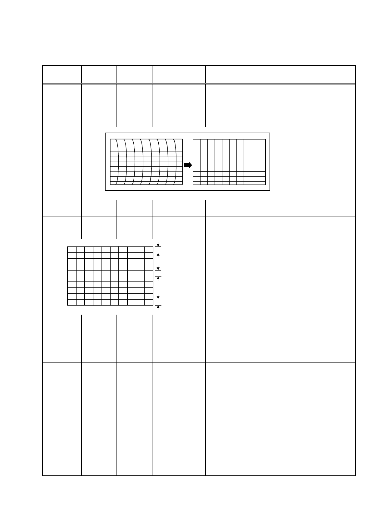
Item
Adjustment
of
V-SHIFT
Adjustment
of V-SIZE
Screen
size
Measuring
instrument
Signal
generator
Remote
control unit
Test point Adjustment part Description
1. V- SHIFT
A
B
2.V-SIZE
Screen size
Picture
size
100%
[FULL mode]
1. Rec eive a c ir c l e pattern signal of vertical frequ ency 50Hz.
2. Select 4.DEF from the SERVICE MENU.
3. Select 1.V-SHIFT with the FUNCTION UP/DOWN key.
4. Adjust V-SHIFT to make
5. Check the adjustment value above in other zoom mode.
If it is a wrong adjustm ent, re-adjus t in “PANORA MIC” mode
and adjus t b y 1. V-SH I FT.
6. Press th e MEN U k ey an d m em or i z e the set value.
7. Receive a cross-hatch signal.
8. Select 2.V-SIZE and set the initial setting value.
9. Adj ust V-S IZE and mak e sure that t he ver tic al screen siz e of
the picture size is in the bellow table.
10. Press the MEN U k ey and memorize the set value.
11. Input a NTSC VIDEO sign al (60Hz) from th e EXT terminal,
and make sure that the vertical screen size is in the table
below.
12. Press the MEN U k ey and memorize the set value.
A = B
.
Picture size 100%
ASPECT
SCREEN
POSITION
TOP
BOTTOM 92% 87% 83%
26
FULL PANORAMIC
92% 87% 70%
[ SCREEN SIZE ]
SUB TITLE
No. 51780
Page 27

A
V32X10EUS
A
A
A
V28X10EUS
V28X10EKS
V28X10EIS
Item
Adjustment of
H.CENTER
Adjustment
of
H.SIZE
Measuring
instrument
Signal
generator
Remote
control unit
CD
Test point Adjustment part Description
3.H-CENT.
4.H-SIZE
13. Receive a circ l e pattern sig n al.
14. Select 3.H-CENT and set the initial setting value.
15. Adjust H-CENT to make
16. Press the MENU k ey an d memori z e th e s et val u e.
17. Receive a cross-hatch signal.
18. Select 4.H-SIZE and set the initial setting value.
19. Adjust H -SIZE and make sur e t hat t he hori zontal s cr een s ize
of the picture size is in the bellow table.
20. Press the MENU k ey an d memori z e th e s et val u e.
21. Input a NTSC VIDEO signal (60Hz) from the EXT terminal, and
make sure that the horizontal screen size is in the table below.
22. Press the MENU k ey an d memori z e th e s et val u e.
C=D
.
ASPECT
MODE
H-SIZE
Adjustment of
EW-PIN
FULL PANORAMIC
92% 95% 92%
[ SCREEN SIZE ]
6.EW-PIN
Straight
SUBTITLE
23. Select 6.EW-PIN and set the initial setting value
24. Adjus t EW-PI N and m ake t h e 2nd .ver tic al li nes at t he l eft and
right edg es of t h e s c reen str ai ght. Also make s ure that th e 3r d
vertical lines are straight.
25. Press the MENU k ey an d memori z e th e s et val u e.
No. 51780
27
Page 28

A
V32X10EUS
A
A
A
V28X10EUS
V28X10EKS
V28X10EIS
Item
Adjustment
of TRAPEZ
Adjustment of
CORNER
UP/ LOW
Measuring
instrument
Signal
generator
Remote
control unit
Signal
generator
Remote
control unit
Straight Straight
Test point Adjustment part Desc ription
5.TRAPEZ
Parallel
7.COR-PIN
8.COR-UP
9.COR-LO
26. Receive a cross-hatch signal.
27. Select 5.TRAPEZ with the FUNCTION UP/DOWN key.
28. Set the initial setting value of TRAPEZ with the FUNCTION or + key.
29. Adjust T RAPEZ and bring the VERTICAL lines at the right and
left edges of the screen parallel .
30. Press the MENU k ey an d memori z e th e s et val u e.
31. Select 9.COR-LO with the FUNCTION UP / DOWN key.
32. Set the initial setting value of COR-LO with the FUNCTION –
or + key.
33. Adjust COR-LO, and bring the straight line at the low corner.
34. Select 8.COR-UP with the FUNCTION UP / DOWN key.
35. Set the initial setting value of COR-UP with the FUNCTION –
or + key.
36. Adjust COR-UP, and bring the straight line at the upper
corner.
37. If the extrem e upper & lower corners and a litt le pin or barr el,
chose 7.CO R -PIN and adj us t.
And adjust to get the straight. Store the set value.
Adjustment of
ANGLE
Signal
generator
Remote
control unit
28
10.ANGLE
No. 51780
In case where there is a parallelogrammical distortion of
"
images on the screen. (Fig. A)
38. Select 10.ANGLE with the FUNCTION UP / DOWN key.
39. Adjust ANGLE, and bring the VERTICAL lines straight.
40. Press the MENU k ey an d memori z e th e s et val u e.
Fig. A
Page 29
A
V32X10EUS
A
A
A
V28X10EUS
V28X10EKS
V28X10EIS
Item
Adjustment
of BOW
Adjustment
of V-S.CR &
V.LINE
Measuring
instrument
Signal
generator
Remote
control unit
Test point Adjustment part Desc ription
11.BOW
Fig. C
12.V-S.CR
13.V.LIN.
TOP
CENTER
BOTTOM
In c ase where t here is a bow-sh aped dist ortion of im ages on
"
the screen. (Fig.C)
41. Select 11.BOW with the FUNCTION UP/DOWN key.
42. Adjust BOW, and bring the VERTICAL lines straight.
43. Press the MENU k ey an d memori z e th e s et val u e.
When the ver tic al linear ity has been deter iorat ed rem ark ably,
!
perform the following steps.
44. Receive a cross-hatch signal.
45. Select 13. V.LIN with the FUNCTION UP / DOWN key.
46. Set the initial setting value of 13. V.LIN with the FUNCTION
- / + key.
47. Select 12. V-S.CR. with the FUNCTION UP / DOWN key.
48. Set the initial setting value of 12. V-S.CR. with the FUNCTION
- / + key.
49. Adjust 13. V .LIN and 12. V -S.CR . so that th e spac es of each
line on TOP, C EN T E R , an d BOTTOM bec om e u niform.
NOTE : Do not adjust “PANORAMIC” & “SUBTITLE” mode.
At first t he adjus tm ent in 1 00Hz FUL L mo de sh ould b e done,
then th e data for th e other aspect mode is corrected in the
respect ive valu e at th e same tim e. And c onfirm t he defl ection
adjust ment initial s etting value in 120H z (NTSC EXT mode)
FULL mode. If the adjust m ent in 100Hz each asp ec t m od e has
been don e and st ored, the dat a for the s ame as pect m odes in
120Hz is c orrect ed in the r espect ive value. O nly th e data f or
the other as pect mode in 12 0H z is c orrec ted for its elf .
No. 51780
29
Page 30

A
V32X10EUS
A
A
A
V28X10EUS
V28X10EKS
V28X10EIS
AUDIO CIRCUIT ADJUSTMENT
Do not touch
"
If values had changed for the some reason, set the initial values in the following table.
3. AUDIO(Do not adj ust)
1. ERR LIMIT 00H~FFH 10H
3. AUDIO
Sett ing item Variable ran ge fixed value
adjust m ent of t h e SER V IC E MENU as it req ui res no adjus tment.
2. A2 ID THR
00H~FFH
19H
30
No. 51780
Page 31

A
A
A
A
REPLACEMENT OF CHIP COMPONENT
CAUTIONS
!
1. Avoid heating for more than 3 seconds.
2. Do not rub the electrodes and the resist parts of the pattern.
3. When removing a chip part, melt the solder adequately.
4. Do not r euse a chip part after removi ng it.
SOLDERING IRON
!
1. Use a high ins ul at i on s old er in g ir on wi th a t hi n p oint ed end of it.
2. A 30w soldering iron is recommended for easily removing parts.
REPLACEMEN T STEPS
!
How to remove Chip parts
1.
Resistors, capacitors, etc
####
(1) As shown in the figure, push the part with tweezers and
alternately melt t h e s old er at eac h en d.
(2) S hif t wi th tweezers an d rem ove the chip p ar t.
Transistors, diodes, variable resistors, etc
####
(1) Apply extra solder to each lead.
V32X10EUS
V28X10EUS
V28X10EKS
V28X10EIS
2. How to install Chip part s
Resistors, capacitors, etc
####
(1) Apply solder to the pattern as indicated in the figure.
(2) Grasp th e chip part with tw eezers and pl ace it on th e sold er.
Then heat an d m elt t h e s old er at b oth en ds of th e chip part .
Transistors, diodes, variable resistors, etc
####
(1) Apply solder to the pattern as indicated in the figure.
(2) Grasp the chip part with tweezers and place it on the solder.
(3) First solder lead
as indicated in the figure.
A
SOLDER
(2) As shown in the figure, push the part with tweezers and
alternat el y melt t he s old er at each lead . Shif t and r emov e th e
chip part.
Note : After removing the part, remove remaining solder from the
pattern.
SOLDER
No.51780
A
(4) Then solder leads
A
C
and C.
B
C
B
B
31
Page 32

A
V32X10EUS
A
A
A
V28X10EUS
V28X10EKS
V28X10EIS
32
No.51780
Page 33

V
ICTOR COMPANY OF JAPAN, LIMITED
HOME AV NETWORK BUSINESS UNIT 12, 3-chome, Moriya-cho, Knagawa-ku, Yokohama, Kanagawa-prefecture, 221-8528, Japan
4
AV32X10EUS-U #4 AV28X10EUS-U #4
AV28X10EKS-U #3 AV28X10EIS-U #4
Printed in Japan
VP 0105
DP1058
 Loading...