

Page 1
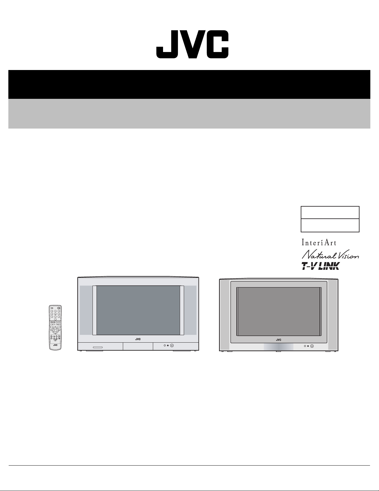
SERVICE MANUAL
COLOUR TELEVISION
YA06020043
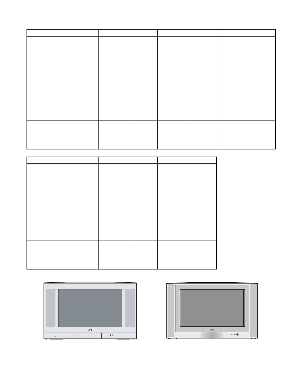
AV-28R4SK, AV-28T4BK, AV-28T4SK,
AV-28T4SP, AV-28T4BR, AV-28T4SR,
AV-28T77SK, AV-32R4SK, AV-32T4SK,
AV-32T4SP, AV-32T4SR, AV-32T77SK
BASIC CHASSIS
JW
1
2
3
4
5
6
7
8
9
0
AV
MENU
P
TV OK
P
.T/L
F
TV
AV-28R4SK, AV-28T4BK, AV-28T4SK,
AV-28T4SP, AV-28T4BR, AV-28T4SR,
AV-28T77SK
AV-32T77SK
AV-32R4SK, AV-32T4SK, AV-32T4SP,
AV-32T4SR
TABLE OF CONTENTS
1 PRECAUTION. . . . . . . . . . . . . . . . . . . . . . . . . . . . . . . . . . . . . . . . . . . . . . . . . . . . . . . . . . . . . . . . . . . . . . . . . 1-4
2 SPECIFIC SERVICE INSTRUCTIONS . . . . . . . . . . . . . . . . . . . . . . . . . . . . . . . . . . . . . . . . . . . . . . . . . . . . . . 1-6
3 DISASSEMBLY . . . . . . . . . . . . . . . . . . . . . . . . . . . . . . . . . . . . . . . . . . . . . . . . . . . . . . . . . . . . . . . . . . . . . . . 1-9
4 ADJUSTMENT . . . . . . . . . . . . . . . . . . . . . . . . . . . . . . . . . . . . . . . . . . . . . . . . . . . . . . . . . . . . . . . . . . . . . . . 1-18
5 TROUBLE SHOOTING. . . . . . . . . . . . . . . . . . . . . . . . . . . . . . . . . . . . . . . . . . . . . . . . . . . . . . . . . . . . . . . . . 1-34
COPYRIGHT © 2004 VICTOR COMPANY OF JAPAN, LIMITED
No.YA060
2004/3
Page 2
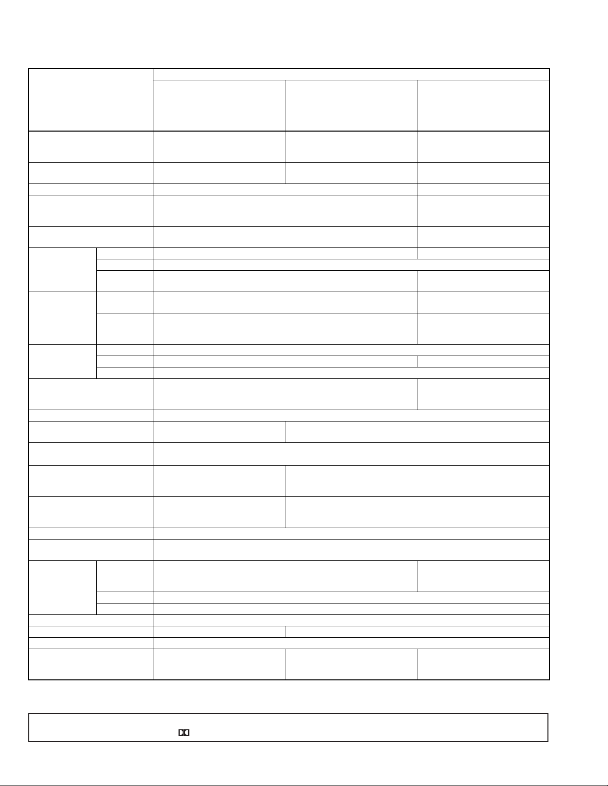
SPECIFICATION
Contents
AV-28T4SK
Items
Dimensions ( W × H × D ) 85.4cm × 50.8cm × 49.7cm 85.4cm × 50.7cm × 49.7cm
Mass 42.0kg 42.0kg
TV RF System CCIR ( I ) CCIR (B/G, I, L)
Colour System PAL
NTSC3.58 / NTSC4.43 (Only EXT mode)
Stereo System NICAM ( I ) A2 (B/G)
Receiving
Frequency
French CATV --- 116MHz - 172MHz
Intermediate
Frequency
Colour Sub
Carrier Frequency
Teletext System FLOF (Fastext level 2.5)
Power Input AC 220V~AC240V, 50Hz
Power Consumption 125W(Max) / 115W(Avg)
Picture Tube Visible size : 66cm [measured diagonally] (H : 58.3cm × V : 33.0cm)
High Voltage 31.0kV (+1kV / -1.5kV) (at zero beam current)
Speaker MAIN : 6.5cm × 13cm oval type × 2
Audio Power Output MAIN : 10W + 10W
Aerial Input Terminal 75 Ω unbalanced, coaxial
EXT-1 / EXT-2 / EXT-3
(Input / Output)
EXT-4 S-Video Mini-DIN 4-pin × 1
Audio Out (variable) 0 - 1000V(rms), low impedance, RCA pin jack × 2
Surround Rear Terminal 7.5W + 7.5W, 8 Ω ---
Headphone Jack Stereo mini jack, Ø3.5mm × 1
Remote Control Unit RM-C1502-1C
VHF --- 47MHz - 470MHz
UHF 470MHz - 862MHz
VIF 38.9MHz ( I ) 38.9MHz (B/G, I, L)
SIF 32.9MHz (6.0MHz :I) 33.4MHz (5.5MHz :B/G)
PAL 4.43MHz
SECAM --- 4.40625MHz / 4.25MHz
NTSC 3.58MHz / 4.43MHz
WST(Standard system)
Standby : 2.7W
CENTER : 4cm × 16cm oval type × 2
SUB WOOFER : 13cm round type × 1
CENTER : 10W
SUB WOOFER : 18W
21-pin Euro connector (SCART socket × 3)
Y : 1V(p-p) positive, negative sync 75Ω
C : 0.286V(p-p) (burst signal) 75Ω
Video 1V(p-p) positive, negative sync provided, 75Ω, RCA pin jack × 1
Audio 500mV(rms) (-4dBs), high impedance, RCA pin jack × 2
(AA/R6 dry cell battery × 2)
AV-28R4SK
85.4cm × 50.7cm × 48.9cm
[AV-28T77SK]
39.0kg [AV-28T77SK]
120W(Max) / 110W(Avg)
Standby : 2.7W
6.5cm × 13cm oval type × 2
10W + 10W
RM-C1502-1C (Silver)
RM-C1502B-1C (Black)
(AA/R6 dry cell battery × 2)
Design & specifications are subject to change without notice.
[AV-28R4SK]
This product is manufactured under license from Dolby Laboratories Licensing Corporation.
"Dolby" and the double-D symbol are trademarks of Dolby Laboratories Licensing Corporation.
AV-28T4BK
AV-28T4SR
AV-28T4BR
AV-28T77SK
AV-28T4SP
85.4cm × 50.8cm × 49.3cm
39.0kg
PAL
SECAM
NTSC3.58 / NTSC4.43 (Only EXT mode)
NICAM (B/G, I, L)
220MHz - 469MHz
33.9MHz (L')
32.9MHz ( 6.0MHz:I )
32.4MHz (6.5MHz :L)
TOP (German system)
FLOF (Fastext level 2.5 720P)
WST (Standard system)
RM-C1502-1C
(AA/R6 dry cell battery × 2)
---
1-2 (No.YA060)
Page 3
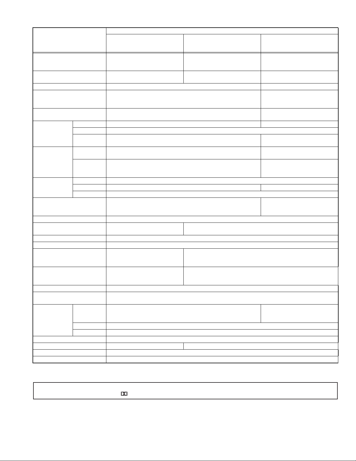
Contents
Items
Dimensions ( W × H × D ) 94.8cm × 56.2cm × 55.4cm 94.8cm × 56.2cm × 55.4cm
Mass 56.0kg 56.0kg
TV RF System CCIR ( I ) CCIR (B/G, I, L)
Colour System PAL
NTSC3.58 / NTSC4.43 (Only EXT mode)
Stereo System NICAM ( I ) A2 (B/G)
Receiving
Frequency
French CATV --- 116MHz - 172MHz
Intermediate
Frequency
Colour Sub
Carrier Frequency
Teletext System FLOF (Fastext level 2.5)
Power Input AC 220V~AC240V, 50Hz
Power Consumption 125W(Max) / 115W(Avg)
Picture Tube Visible size : 76cm [measured diagonally] (H : 67.4cm × V : 38.4cm)
High Voltage 31.0kV (+1kV / -1.5kV) (at zero beam current)
Speaker MAIN : 6.5cm × 13cm oval type × 2
Audio Power Output MAIN : 10W + 10W
Aerial Input Terminal 75 Ω unbalanced, coaxial
EXT-1 / EXT-2 / EXT-3
(Input / Output)
EXT-4 S-Video Mini-DIN 4-pin × 1
Audio Out (variable) 0 - 1000V(rms), low impedance, RCA pin jack × 2
Surround Rear Terminal 7.5W + 7.5W, 8 Ω ---
Headphone Jack Stereo mini jack (Ø3.5mm × 1)
Remote Control Unit RM-C1502-1C (AA/R6 dry cell battery × 2)
VHF --- 47MHz - 470MHz
UHF 470MHz - 862MHz
VIF 38.9MHz ( I ) 38.9MHz (B/G, I, L)
SIF 32.9MHz (6.0MHz :I) 33.4MHz (5.5MHz :B/G)
PAL 4.43MHz
SECAM --- 4.40625MHz / 4.25MHz
NTSC 3.58MHz / 4.43MHz
WST(Standard system)
Standby : 2.7W
CENTER : 4cm × 16cm oval type × 2
SUB WOOFER : 13cm round type × 1
CENTER : 10W
SUB WOOFER : 18W
21-pin Euro connector (SCART socket × 3)
Y : 1V(p-p) positive, negative sync 75Ω
C : 0.286V(p-p) (burst signal) 75Ω
Video 1V(p-p) positive, negative sync provided, 75Ω, RCA pin jack × 1
Audio 500mV(rms) (-4dBs), high impedance, RCA pin jack × 2
AV-32R4SK
94.6cm × 56.2cm × 54.7cm
[AV-32T77SK]
53.0kg [AV-32T77SK]
120W(Max) / 110W(Avg)
Standby : 2.7W
6.5cm × 13cm oval type × 2
10W + 10W
AV-32T4SK
AV-32T4SR
AV-32T77SK
AV-32T4SP
94.8cm × 56.2cm × 55.0cm
53.0kg
PAL
SECAM
NTSC3.58 / NTSC4.43 (Only EXT mode)
NICAM (B/G, I, L)
220MHz - 469MHz
33.9MHz (L')
32.9MHz ( 6.0MHz:I )
32.4MHz (6.5MHz :L)
TOP (German system)
FLOF (Fastext level 2.5 720P)
WST (Standard system)
Design & specifications are subject to change without notice.
[AV-32R4SK]
This product is manufactured under license from Dolby Laboratories Licensing Corporation.
"Dolby" and the double-D symbol are trademarks of Dolby Laboratories Licensing Corporation.
---
(No.YA060)1-3
Page 4

SECTION 1
PRECAUTION
1.1 SAFETY PRECAUTIONS [EXCEPT FOR UK]
(1) The design of this product contains special hardware,
many circuits and components specially for safety
purposes. For continued protection, no changes should be
made to the original design unless authorized in writing by
the manufacturer. Replacement parts must be identical to
those used in the original circuits. Service should be
performed by qualified personnel only.
(2) Alterations of the design or circuitry of the products should
not be made. Any design alterations or additions will void
the manufacturer's warranty and will further relieve the
manufacturer of responsibility for personal injury or
property damage resulting therefrom.
(3) Many electrical and mechanical parts in the products have
special safety-related characteristics. These
characteristics are often not evident from visual inspection
nor can the protection afforded by them necessarily be
obtained by using replacement components rated for
higher voltage, wattage, etc. Replacement parts which
have these special safety characteristics are identified in
the parts list of Service manual. Electrical components
having such features are identified by shading on the
schematics and by ( ) on the parts list in Service
manual. The use of a substitute replacement which does
not have the same safety characteristics as the
recommended replacement part shown in the parts list of
Service manual may cause shock, fire, or other hazards.
(4) Don't short between the LIVE side ground and
ISOLATED (NEUTRAL) side ground or EARTH side
ground when repairing.
Some model's power circuit is partly different in the GND.
The difference of the GND is shown by the LIVE : ( ) side
GND, the ISOLATED (NEUTRAL) : ( ) side GND and
EARTH : ( ) side GND.
Don't short between the LIVE side GND and ISOLATED
(NEUTRAL) side GND or EARTH side GND and never
measure the LIVE side GND and ISOLATED (NEUTRAL)
side GND or EARTH side GND at the same time with a
measuring apparatus (oscilloscope etc.). If above note will
not be kept, a fuse or any parts will be broken.
(5) If any repair has been made to the chassis, it is
recommended that the B1 setting should be checked or
adjusted (See B1 POWER SUPPLY check).
(6) The high voltage applied to the picture tube must conform
with that specified in Service manual. Excessive high
voltage can cause an increase in X-Ray emission, arcing
and possible component damage, therefore operation
under excessive high voltage conditions should be kept to
a minimum, or should be prevented. If severe arcing
occurs, remove the AC power immediately and determine
the cause by visual inspection (incorrect installation,
cracked or melted high voltage harness, poor soldering,
etc.). To maintain the proper minimum level of soft X-Ray
emission, components in the high voltage circuitry
including the picture tube must be the exact replacements
or alternatives approved by the manufacturer of the
complete product.
(7) Do not check high voltage by drawing an arc. Use a high
voltage meter or a high voltage probe with a VTVM.
Discharge the picture tube before attempting meter
connection, by connecting a clip lead to the ground frame
and connecting the other end of the lead through a 10kΩ
2W resistor to the anode button.
(8) When service is required, observe the original lead dress.
Extra precaution should be given to assure correct lead
dress in the high voltage circuit area. Where a short circuit
has occurred, those components that indicate evidence of
overheating should be replaced. Always use the
manufacturer's replacement components.
(9) Isolation Check (Safety for Electrical Shock Hazard)
After re-assembling the product, always perform an
isolation check on the exposed metal parts of the cabinet
(antenna terminals, video/audio input and output terminals,
Control knobs, metal cabinet, screw heads, earphone jack,
control shafts, etc.) to be sure the product is safe to operate
without danger of electrical shock.
a) Dielectric Strength Test
The isolation between the AC primary circuit and all metal
parts exposed to the user, particularly any exposed metal
part having a return path to the chassis should withstand a
voltage of 3000V AC (r.m.s.) for a period of one second. (.
. . . Withstand a voltage of 1100V AC (r.m.s.) to an
appliance rated up to 120V, and 3000V AC (r.m.s.) to an
appliance rated 200V or more, for a period of one second.)
This method of test requires a test equipment not generally
found in the service trade.
b) Leakage Current Check
Plug the AC line cord directly into the AC outlet (do not use
a line isolation transformer during this check.). Using a
"Leakage Current Tester", measure the leakage current
from each exposed metal part of the cabinet, particularly
any exposed metal part having a return path to the chassis,
to a known good earth ground (water pipe, etc.). Any
leakage current must not exceed 0.5mA AC (r.m.s.).
However, in tropical area, this must not exceed 0.2mA AC
(r.m.s.).
Alternate Check Method
Plug the AC line cord directly into the AC outlet (do not
use a line isolation transformer during this check.). Use
an AC voltmeter having 1000Ω per volt or more
sensitivity in the following manner. Connect a 1500Ω
10W resistor paralleled by a 0.15µF AC-type capacitor
between an exposed metal part and a known good earth
ground (water pipe, etc.). Measure the AC voltage
across the resistor with the AC voltmeter. Move the
resistor connection to each exposed metal part,
particularly any exposed metal part having a return path
to the chassis, and measure the AC voltage across the
resistor. Now, reverse the plug in the AC outlet and
repeat each measurement. Any voltage measured must
not exceed 0.75V AC (r.m.s.). This corresponds to
0.5mA AC (r.m.s.).
However, in tropical area, this must not exceed 0.3V AC
(r.m.s.). This corresponds to 0.2mA AC (r.m.s.).
AC VOLTMETER
(HAVING 1000 /V,
OR MORE SENSITIVITY)
0.15 F AC-TYPE
PLACE THIS PROBE
1500 10W
GOOD EARTH GROUND
ON EACH EXPOSED
ME TAL PAR T
1-4 (No.YA060)
Page 5

1.2 SAFETY PRECAUTIONS [FOR UK]
(1) The design of this product contains special hardware and many circuits and components specially for safety purposes. For
continued protection, no changes should be made to the original design unless authorized in writing by the manufacturer.
Replacement parts must be identical to those used in the original circuits. Service should be performed by qualified personnel
only.
(2) Alterations of the design or circuitry of the product should not be made. Any design alterations or additions will void the
manufacturer's warranty and will further relieve the manufacturer of responsibility for personal injury or property damage
resulting therefrom.
(3) Many electrical and mechanical parts in the product have special safety-related characteristics. These characteristics are often
not evident from visual inspection nor can the protection afforded by them necessary be obtained by using replacement
components rated for higher voltage, wattage, etc. Replacement parts which have these special safety characteristics are
identified in the Parts List of Service Manual. Electrical components having such features are identified by shading on the
schematics and by ( ) on the Parts List in the Service Manual. The use of a substitute replacement which does not have the
same safety characteristics as the recommended replacement part shown in the Parts List of Service Manual may cause shock,
fire, or other hazards.
(4) The leads in the products are routed and dressed with ties, clamps, tubing’s, barriers and the like to be separated from live parts,
high temperature parts, moving parts and / or sharp edges for the prevention of electric shock and fire hazard. When service is
required, the original lead routing and dress should be observed, and it should be confirmed that they have been returned to
normal, after re-assembling.
WARNING
(1) The equipment has been designed and manufactured to meet international safety standards.
(2) It is the legal responsibility of the repairer to ensure that these safety standards are maintained.
(3) Repairs must be made in accordance with the relevant safety standards.
(4) It is essential that safety critical components are replaced by approved parts.
(5) If mains voltage selector is provided, check setting for local voltage.
(No.YA060)1-5
Page 6
SECTION 2
SPECIFIC SERVICE INSTRUCTIONS
2.1 FEATURES
• New chassis design enable use of an interactive on screen
control.
• The TELETEXT SYSTEM has a built-in FASTEXT (UK
system), TOP (German system) and WST (world standard
system) system.
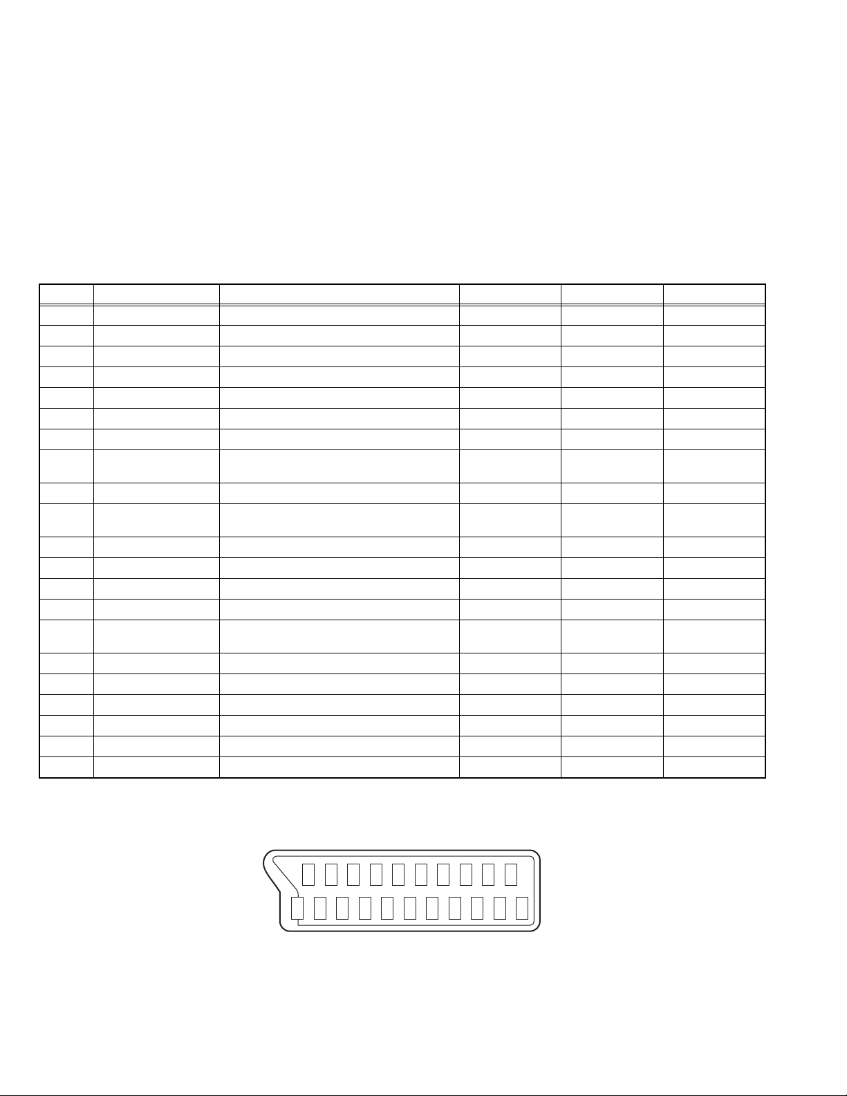
2.2 21-pin Euro connector (SCART) : EXT-1/EXT-2/EXT-3
Pin No. Signal designation Matching value EXT-1 EXT-2 EXT-3
1 AUDIO R output 500mV(rms) (Nominal), Low impedance Used (TV OUT) Used (LINE OUT) Not used
2 AUDIO R input 500mV(rms) (Nominal), High impedance Used (R1) Used (R2) Used (R3)
3 AUDIO L output 500mV(rms) (Nominal), Low impedance Used (TV OUT) Used (LINE OUT) Not used
4 AUDIO GND Used Used Used
5 GND (B) Used Used Used
6 AUDIO L input 500mV(rms) (Nominal), High impedance Used (L1) Used (L2) Used (L3)
7 B input 700mV
FUNCTION SW
8
(SLOW SW)
Low : 0V-3V
High : 8V-12V, High impedance
, 75Ω Used Used Not used
(B-W)
9 GND (G) Used Used Used
10 SCL / T-V LINK Not used
11 G input 700mV
, 75Ω Used Used Not used
(B-W)
12 SDA Not used Used (SDA2) Not used
13 GND (R) Used Used Used
14 GND (YS) Used Not used Not used
15 R / C input
R : 700mV
C : 300mV
(B-W)
(P-P)
, 75Ω
, 75Ω
16 Ys input (FAST SW) Low : 0V-0.4V, High : 1V-3V, 75Ω Used Used Not used
17 GND (VIDEO output) Used Used Used
18 GND (VIDEO input) Used Used Used
19 VIDEO output 1V
20 VIDEO / Y input 1V
(Negative sync), 75Ω Used (TV OUT) Used (LINE OUT) Not used
(P-P)
(Negative sync), 75Ω Used Used Used
(P-P)
21 COMMON GND Used Used Used
• Because this TV unit corresponds to multiplex broadcast,
users can enjoy music programs and sporting events with live
realism. In addition, BILINGUAL programs can be heard in
their original language.
• Users can make VCR dubbing of picture and sound by
controlling the AV selector to select an optional source at the
EXT-2 output.
Used Used Used
Used
(SCL2 / TV-LINK)
Not used
Used (R) Used (C2/R) Used (C3)
(P-P= Peak to Peak, B-W= Blanking to white peak)
[Pin assignment]
20 18 16 14 12 10 8 6 4 2
21 19 17 15 13 11 9 7 5 3 1
1-6 (No.YA060)
Page 7
2.3 MAIN DIFFERENCE LIST
Item AV-28R4SK AV-28T4SK AV-28T4BK AV-28T4SR AV-28T4BR AV-28T77SK AV-28T4SP
CABINET TYPE A ←←←←BA
CABINET COLOUR Silver ← Black Silver Black Silver Silver
DESTINATION England England England Ireland Ireland England Germany
Belgium
France
Switzerand
Austria
Italy
Spain
Portugal
Sweden
Denmark
Finland
Norway
Greece
DOLBY SORROUND YES NO ←←←←←
SUB WOOFER YES NO ←←←←←
POWER PLUG UK type(3pin) ←←←←←EU type(2pin)
S VIDEO INPUT YES ←←←←←NO
Item AV-32R4SK AV-32T4SK AV-32T4SR AV-32T77SK AV-32T4SP
CABINET TYPE A ←←BA
DESTINATION England England Ireland England Germany
Belgium
France
Switzerand
Austria
Italy
Spain
Portugal
Sweden
Denmark
Finland
Norway
Greece
DOLBY SORROUND YES NO ←←←
SUB WOOFER YES NO ←←←
POWER PLUG UK type(3pin) ←←←EU type(2pin)
S VIDEO INPUT YES ←←←NO
CABINET TYPE
B typeA type
(No.YA060)1-7
Page 8
2.4 TECHNINAL INFORMATION
2.4.1 MAIN MI-COM (CPU) PIN FUNCTION
Pin
No.
1 VssP2 -- GND 65 SVM O SVM output
2 VssC4 -- GND 66 FbiSo I/O Flyback input/SC output
3 V1.8C4 -- 1.8VD 67 Hout O H output
4 V3.3A3 -- 3.3V 68 VssComb -- GND for comb filter
5 VrefP_Sdac -- 3.3V 69 V5Comb -- 5V for comb filter
6 VrefN_Sdac -- 0V 70 Vin/R2/Pr I V-input for YUV
7 VrefP_Sdac -- 3.3V 71 Uin/B2/Pb I U-input for YUV
8 VrefN_Sdac -- 0V 72 Yin/G2/Y I Y-input for YUV
9 VrefP_Sdac -- 3.3V 73 Ysync I Y-input for SyncSep
10 XtalIn I XTALIN 74 Yout O Y-out
11 XtalOut O XTALOUT 75 Uout/INSSW2 I/O U-out (2nd RGB/YPbPr insertion input)
12 VssA1 -- GND 76 Vout/Swo1 O NC
13 Vguard/Swo I/O VGUARD or I/O switch 77 INSSW3 I 3rd RGB/YPbPr insertion
14 DecDig -- Decoupling Digital Supply 78 R3/Pr I 3rd R in/Pr in
15 V5P1 -- 1st Supply 5V 79 G3/Y I 3rd G in/Y in
16 Phi2 -- Phase-2 filter 80 B3/Pb I 3rd B in/Pb in
17 Phi1 -- Phase-1 filter 81 Gnd3 -- GND3
18 Gnd1 -- GND1 82 V5P3 -- 3rd supply
19 SecPll -- SECAM PLL Decoupling 83 BCL I BCL input
20 Dec8G -- Bandgap decoupling 84 BLKIN I Black current input
21 Ewd/Avl O E/W Drive or AVL cap. 85 Rout O Red output
22 Vdb O V. Drive B output 86 Gout O Green output
23 Vda O V. Drive A output 87 Bout O Blue output
24 Vif1 I IF input 1 88 V3.3A1 -- 3.3V analog
25 Vif2 I IF input 2 89 RefAdN -- Negative ref. voltage
26 Vsc -- Vertical sawtooth cap. 90 V3.3RefAdP -- Positive ref. voltage
27 Iref I Ref. current input 91 RefAd -- Reference voltage for ADC
28 GndIF -- GND IF 92 GndA -- GND
29 Sif1 I SIF input 1 / DVB input 1 93 V1.8A I Supply for ADC
30 Sif2 I SIF input 2 / DVB input 2 94 V3.3A2 I Supply for SDAC
31 Agc O Tu AGC output 95 VssADC -- GND for Temp. sensor
32 EHT I EHT/overvoltage protect 96 V1.8ADC -- Supply video ADC
33 Ssif/RefIn/Avl/RefOut O L/OTHER 97 IntO I REMOCON
34 AudioIn5L I Audio 5 input (Left) 98 P10/Int1 I AV_LINK IN
35 AudioIn5R I Audio 5 input (Right) 99 P11/TO O AV_LINK OUT
36 AudOutSL O Audio output (Left) 100 V1.8C2 -- digital 1.8V
37 AudOutSR O Audio output (Right) 101 VssC2 -- GND
38 DecsDem -- decoupling sound demod. 102 P04/I2SWs I/O (I2S_WS)
39 QssO/AmO/AudeEm O QSSO/AMout/deemphasis 103 P03/I2SClk I/O (I2S_CLK)
40 Gnd2 -- GND2 104 P02/I2SDo2 O L/R_OTH (I2S_Dout2)
41 PllIf -- IF PLL loop filter 105 P01/I2SDo1 O D/A_RST (I2S_Dout1)
42 SifAgc -- AGC SIF / int-extAGCforDVB 106 P00/I2SDI1 I H/P DET
43 IfVo/FmRo/DvbO O DVBout/IFvideo/FMout 107 P13/T1 O POWER
44 FmRo/DvbO O DVBout/FMout 108 SCL1 I/O SCL1
45 V8AudioSwitches -- 8V for Audio SW. 109 SDA1 I/O SDA1
46 AgcSsif -- AGC cap.2nd SIF 110 V3.3P -- 3.3V
47 V5P2 -- 2nd supply 5V 111 P20/TPwm O ROTATION (or N/S CANCEL)
48 SVO/IfVo/Cvbsl I/O IF vout/selCVBSo/CVBSin 112 P21/Pwm0 O (N/S_CEN/OTH)
49 Audio4InL I Audio 4 input (Left) 113 P22/Pwm1 O A_MUTE
50 Audio4InR I Audio 4 input (Right) 114 P23/Pwm2 O AMP_MUTE
51 Y4/Cvbs4 I CVBS4/Y4 input 115 P30/Adc0 I PROTECT
52 C4 I Chroma-4 input 116 P31/Adc1 O LED
53 Audio2InL I Audio 2 input (Left) 117 V1.8C1 -- 1.8V digital
54 Audio2InR I Audio 2 input (Right) 118 DecV1V8 -- Decoupling 1.8V
55 Cvbs2/Y I CVBS2/Y2 input 119 P32/Adc2 I KEY input
56 Audio3InL I Audio 3 input (Left) 120 P33/Adc3 I AGC input (ECO)
57 Audio3InR I Audio 3 input (Right) 121 VssC1+P1 I Digital GND m controller
58 Y3/Cvbs I CVBS3/Y3 input 122 P24/PWM3 O NC(SAW_SW)
59 C3 I Chroma-2/3 input 123 P25/PWM4 O RES_OUT
60 AudOutLsL I Audio output for AMP 124 V1.8C3 -- 1.8V digital
61 AudOutLsR I Audio output for AMP 125 VssC3 -- GND
62 AudOutHpL I HP L Audio output 126 P12/Int2 I POW_DET
63 AudOutHpR I HP-R Audio ouput 127 P14/RX I/O SDA0
64 CVBSO/PIP I/O CVBS/PIP output 128 P15/TX I/O SCL0
Pin name I/O Function
Pin
No.
Pin name I/O Function
1-8 (No.YA060)
Page 9
SECTION 3
DISASSEMBLY
3.1 DISASSEMBLY PROCEDURE
The illustration of Fig.5 is explained about AV-28R4SK/AV-32R4SK.
In case of AV-28T Series or AV-32T Series MODELS, you disassemble in the same procedure using Fig.6.
3.1.1 REMOVING THE REAR COVER
(1) Unplug the power plug.
(2) Remove the sub woofer cord from the AV TERMINAL
BOARD.
(3) Remove the SUB WOOFER UNIT on the top of the rear
cover upward.
(4) Remove the 13 screws [A] as shown in Fig.5.
(5) Withdraw the REAR COVER toward you.
3.1.2 REMOVING THE SIDE CONTROL JACK ASSY
• Remove the REAR COVER.
(1) Remove the screw [B] as shown in Fig.5.
(2) Slightly pull the SIDE CONTROL JACK ASSY toward you,
and detach the claw from FRONT CABINET.
Then it can be removed.
(3) Then disconnect the connector [S], [F] and [K] as shown
in Fig 1.
3.1.3 REMOVING THE SIDE CONTROL PWB
• Remove the REAR COVER.
• Remove the SIDE CONTROL JACK ASSY.
(1) Remove the 3 claws [C] from backside of the SIDE
CONTROL JACK ASSY as shown in Fig.1.
(2) Remove the SIDE CONTROL PWB from the SIDE
CONTROL JACK ASSY.
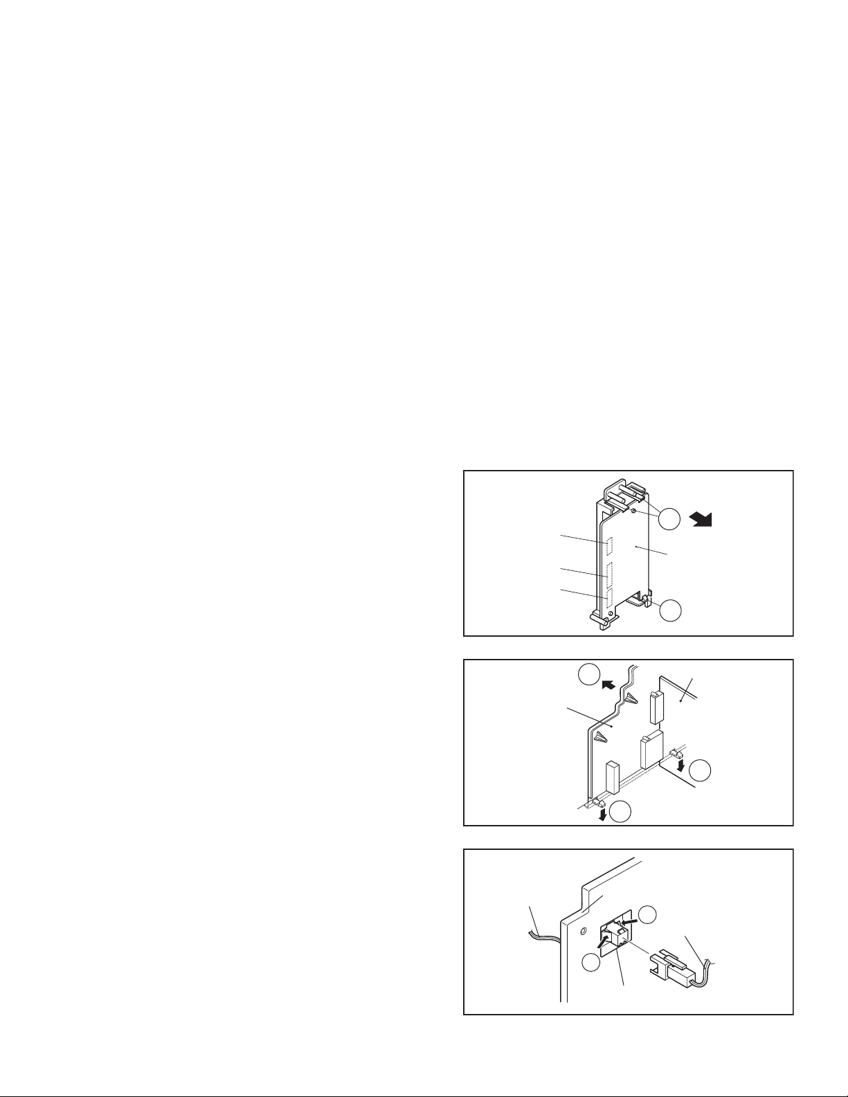
3.1.4 REMOVING THE AV TERMINAL BOARD
• Remove the REAR COVER.
(1) Remove the 5 screws [G] as shown in Fig. 5.
(2) Remove the 2 claws [H] at the bottom of the AV
TERMINAL BOARD as shown in Fig. 2.
(3) Shift the AV TERMINAL BOARD slightly in the direction of
arrow [I], and remove it as shown in Fig. 2.
(4) At first, expand the lever [K] with the SUB WOOFER connector,
and pull it out of connector jack as shown in Fig.3.
3.1.5 REMOVING THE MAIN CHASSIS
• Remove the REAR COVER.
(1) Slightly raise the MAIN CHASSIS, and release the two claws
at the bottom of and both sides of the MAIN CHASSIS.
(2) Then withdraw the MAIN CHASSIS backward from the
front cabinet. (If necessary, detach the wire clamp,
connectors etc.)
3.1.6 REMOVING THE MAIN SPEAKER
• Remove the REAR COVER.
(1) Remove the 2 screws [E], and detach the MAIN SPEAKER
HOLDER as shown in Fig. 5. (When removing the screws
[E] of the MAIN SPEAKER HOLDER, the lower side screw
first, and then upper one.)
(2) Remove the 4 screws [F], which attached the MAIN
SPEAKER.
(3) Follow the same steps when disassemble the other hand
MAIN SPEAKER.
3.1.7 REMOVING THE CENTER SPEAKER
• Remove the REAR COVER.
• Remove the MAIN CHASSIS.
(1) Remove the 2 screws [D] as shown in Fig. 5.
(2) Remove the CENTER SPEAKER. If necessary, detach the
cables.
3.1.8 CHECKING THE PW BOARD
(1) Pull out the MAIN CHASSIS (Refer to REMOVING THE
MAIN CHASSIS).
(2) Erect the CHASSIS vertically with the HVT side facing up
so that you can easily check the back side of the PW board.
3.1.9 CAUTION
(1) When erecting the MAIN CHASSIS, be careful so that
there will be no contacting with other PWB.
(2) Before turning power on, make sure that the wire connector
is properly connected.
(3) When conducting a check with power supplied, be sure to
confirm that the CRT EARTH WIRE (BRAIDED ASS’Y) is
connected to the CRT SOCKET PWB.
3.1.10 WIRE CLAMPING AND CABLE TYING
(1) Be sure to clamp the wire.
(2) Never remove the cable tie used for tying the wires
together.Should it be inadvertently removed, be sure to tie
the wires with a new cable tie.
Connector
C
S
F
K
SIDE
CONTROL
PWB
C
(Back view)
Fig.1
I
AV
TERMINAL
BOARD
H
AV JACK PWB
Fig.2
SUB WOOFER
CORD
AV TERMINAL
BOARD
K
SUB WOOFER
CORD
K
CONNECTOR for
SUB WOOFER
Fig.3
FRONT
H
(No.YA060)1-9
Page 10
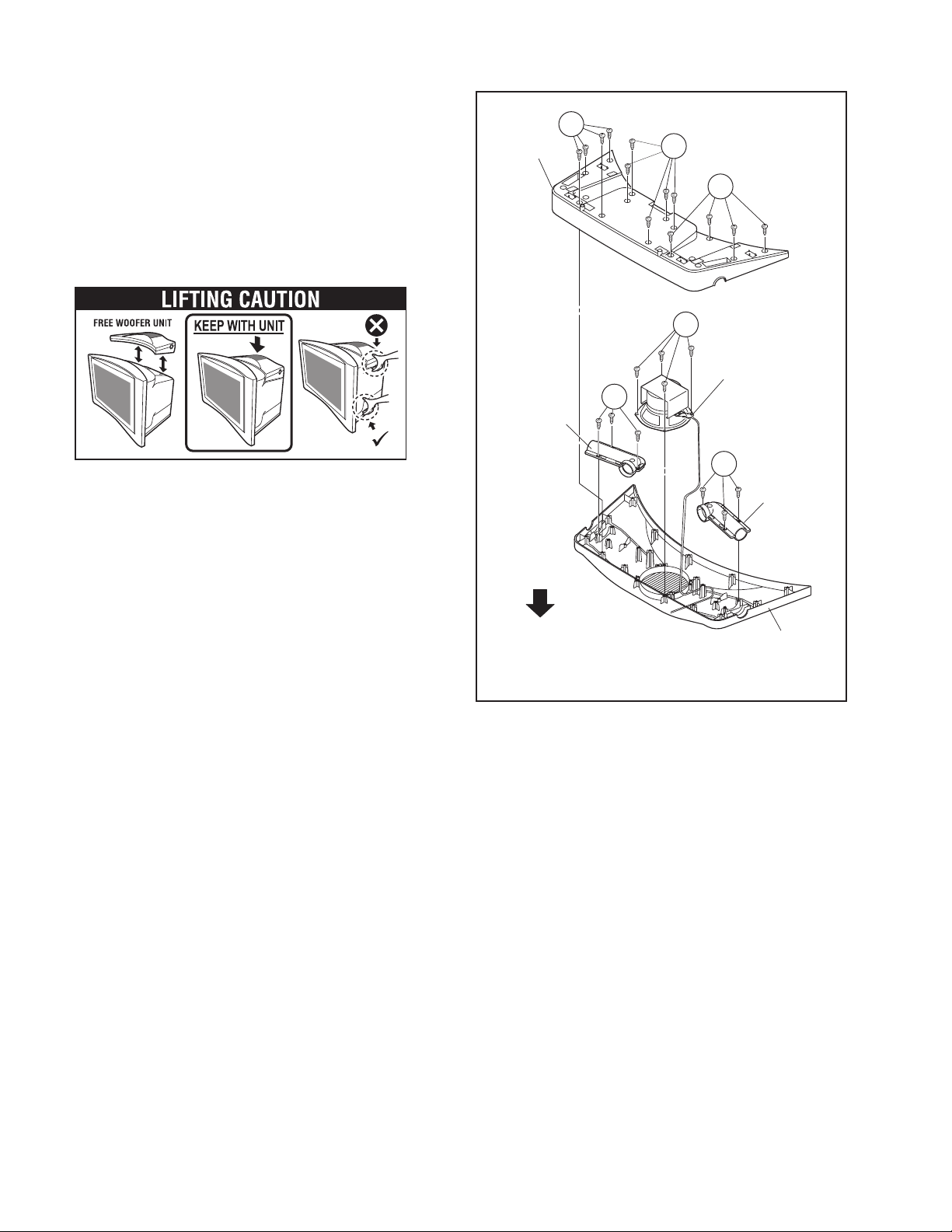
3.1.11 REMOVING THE SUB WOOFER UNIT [AV-28R4SK / AV-32R4SK]
(1) Remove the 15 screws [L], remove the SP BOX B.
(2) Remove the 4 screws [M], remove the SPEAKER.
(3) Remove the 3 screws [N], remove BASS INT. DUCT.
CAUTION
• The woofer unit is mounted on the TV. Always move the TV
and woofer unit together when removing the TV from the
box, or when moving the woofer unit.
• If the TV is tilted during movement the woofer unit may fall.
Be careful to keep the TV level when moving it.
• Do not grip the woofer unit when moving the TV.
• Do not place objects on the woofer unit duct.
SP BOX B
BASS
INT. DUCT
L
L
L
M
SPEAKER
N
N
BASS
INT. DUCT
TOP
SP BOX T
Fig.4
1-10 (No.YA060)
Page 11
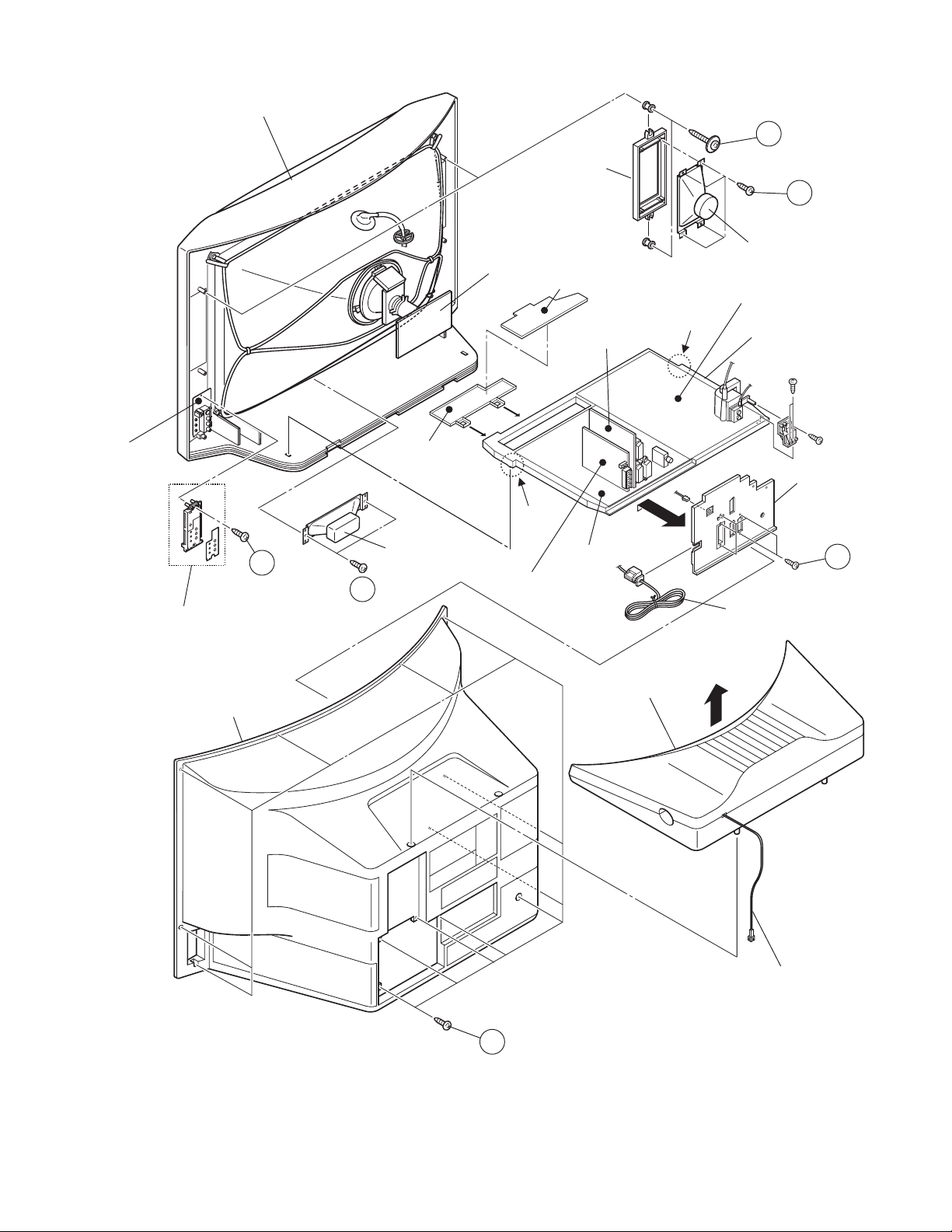
3.1.12 EXPLODED VIEW [AV-28R4SK and AV-32R4SK]
FRONT CABINET
E
MAIN SPEAKER
HOLDER
F
MAIN SPEAKER
CRT SOCKET PWB
FRONT CONTOL PWB
POWER & DEF. PWB
SIDE
CONTROL
PWB
SIDE CONTROL
JACK ASSY
REAR COVER
B
D
CONTROL
BASE
CENTER
SPEAKER
AV JACK PWB
CLAW
MAIN PWB
DOLBY PWB
CLAW
SUB WOOFER UNIT
MAIN CHASSIS
AV TERMINAL
BOARD
G
POWER CORD
A
Fig.5
SUB WOOFER CORD
(No.YA060)1-11
Page 12

3.1.13 EXPLODED VIEW [AV-28T Series and AV-32T Series]
SIDE
CONTROL
PWB
FRONT CABINET
B
CONTROL
BASE
MAIN SPEAKER
HOLDER
CRT SOCKET PWB
FRONT CONTOL PWB
CLAW
MAIN PWB
AV JACK PWB
CLAW
E
F
MAIN
SPEAKER
POWER & DEF.PWB
AV TERMINAL
BOAD
G
SIDE CONTROL
JACK ASSEMBLY
REAR COVER
POWER CORD
This exploded view describes
about AV-32T4SP.
Although other models(AV-28T
series / AV-32T series) are
slightly different from this figure
you can use the exploded view
for disassembling other models
in same step as AV-32T4SP.
A
Fig.6
1-12 (No.YA060)
Page 13

3.1.14 REMOVING THE CRT
NOTE:
• Replacement of the CRT should be performed by 2 or more
persons.
• After removing the REAR COVER, CHASSIS etc.,
(1) Putting the CRT change table on soft cloth, the CRT
change table should also be covered with such soft cloth
(shown in Fig. 6).
(2) While keeping the surface of CRT down, mount the TV set
on the CRT change table balanced will as shown in Fig. 6.
(3) Remove 4 screws marked by arrows with a box type
screwdriver as shown in Fig. 7.
NOTE:
Since the cabinet will drop when screws have been
removed, be sure to support the cabinet with hands.
(4) After 4 screws have been removed, put the cabinet slowly
on cloth (At this time, be carefully so as not to damage the
front
surface of the cabinet) shown in Fig. 8.
NOTE:
• The CRT should be assembled according to the
opposite sequence of its dismounting steps.
• The CRT change table should preferably be smaller
that the CRT surface, and its height be about 35cm.
CRT CHANGE TABLE
CLOTH
CRT
CHANGE
TABLE
Fig.7
CRT
Fig.8
APPROX.
35cm
BOX
TYPE
SCREW
DRIVER
CRT
CABINET
CRT
CHANGE TABLE
Fig.9
COATING OF SILICON GREASE FOR ELECTRICAL INSULATION ON THE CRT ANODE CAP SECTION.
Subsequent to replacement of the CRT and HV transformer or repair of the anode cap, etc. by dismounting them, be sure to coat
silicon grease for electrical insulation as shown in Fig.9.Wipe around the anode button with clean and dry cloth. (Fig.9)Coat silicon
grease on the section around the anode button. At this time, take care so that any silicon greases dose not sticks to the anode
button. (Fig.10)
Silicon grease product No. KS - 650N
CRT
Anode button
Approx.
20mm (Do not
coat grease on
this section
Silicon grease
should be coated
by 5mm or more
from the outside
diameter of anode
cap.
Silicon grease
coating
Fig.10
Anode button
(No sticking of
silicon grease)
Fig.11
Coating position
of silicon grease
Anode cap
(No.YA060)1-13
Page 14

3.2 MEMORY IC REPLACEMENT
• This model uses the memory IC.
• This memory IC stores data for proper operation of the video and drive circuits.
• When replacing, be sure to use an IC containing this (initial value) data.
3.2.1 MEMORY IC REPLACEMENT PROCEDURE
1. Power off
Switch off the power and disconnect the power plug from the
AC outlet.
2. Replace the memory IC
Be sure to use the memory IC written with the initial setting
values.
3. Power on
Connect the power plug to the AC outlet and switch on the
power.
4. System constant check and setting
* It must not adjust without signal.
(1) Press the [INFORMATION] key and the [MUTING] key of
the REMOTE CONTROL UNIT simultaneously.
(2) The SERVICE MENU screen of Fig. 1 will be displayed.
(3) While the SERVICE MENU is displayed, press the
Address
Setting data
[INFORMATION] key and [MUTING] key
simultaneously, and the SYSTEM CONSTANT SET
screen of Fig. 2 will be displayed.
(4) Refer to the "SETTING VALUES OF SYSTEM
CONSTANT SET" , and check the setting items. Where
these differ, select the addres with the [FUNCTION (UP/
DOWN)] key and adjust it with the [FUNCTION (RIGHT/
LEFT)] keys. (The letter of the selected item is displayed
in yellow.)
(5) A setup will become effective if the main power is shut
off.
5. Receiving channel setting
Refer to the OPERATING INSTRUCTIONS and set the
receive channels (Channels Preset) as described.
6. User settings
Check the user setting items according to the given in page
later.
Where these do not agree, refer to the OPERATING
INSTRUCTIONS and set the items as described.
7. SERVICE MENU setting
Verify what to set in the SERVICE MENU, and set whatever is
necessary (Fig.1). Refer to the SERVICE ADJUSTMENT for
setting.
SERVICE MENU
1. IF 2. V/C
3. AUDIO 4. DEF
5. VSM PRESET 6. VPS
7. SHIPPING (OFF)
MODEL=JW EURO (XXXXX)
Fig.1
EEP EDIT (LAST MEMORY)
TOP ADDRESS=000H
00 01 02 03 04 05 06 07
8F 00 FE FF FF FF FF FF
08 09 0A 0B 0C 0D 0E 0F
FF 01 BB FC 1F F9 FF FF
Fig.2
NAME OF REMOTE CONTROL KEY
Names of key
INFORMATION
MUTING
MENU
FUNCTION UP/DOWN
FUNCTION -/+
key
OK
Do not adjust
3.2.2 SYSTEM CONSTANT SETTING
Setting data
Address
AV-28R4SK
00 8F 8B CF CF 89 9F 9B DF DF 99
01 00 00 02 01 00 00 00 02 01 00
AV-28T4SK
AV-28T4BK
AV-28T4SP
AV-28T4SR
AV-28T4BR
AV-28T77SK AV-32R4SK AV-32T4SK AV-32T4SP AV-32T4SR AV-32T77SK
1-14 (No.YA060)
Page 15

3.2.3 SETTINGS OF FACTORY SHIPMENT
3.2.3.1 BUTTON OPERATION 3.2.3.2 REMOTE CONTROL DIRECT OPERATION
Setting item Setting position
POWER Off
CHANNEL PR1
VOLUME 10
3.2.3.3 REMOTE CONTROL MENU OPERATION
(1) PICTURE
CHANNEL PR1
VOLUME 10
ZOOM PANORAMIC
3D SOUND OFF
(3) FEATURES
Setting item Setting position
Setting item Setting position
PICTURE MODE STANDARD
CONTRAST / BRIGHT
SHARP / COLOUR / HUE
COLOUR TEMP. NORMAL
FEATURES
AUTO VNR AUTO
COLOUR SYSTEM TV According to preset CH
4:3 AUTO ASPECT PANORAMIC
(2) SOUND
Setting item Setting position
STEREO / I•II Stereo sound
BASS Centre
TREBLE Centre
BALANCE Centre
HYPER SOUND OFF
DOLBY VIRTUAL
[AV-28T77SK/AV-32T77SK]
TV SPEAKER
[AV-28R4SK/AV-32R4SK]
SUROUND MODE
[AV-28R4SK/AV-32R4SK]
DOLBY
PRO LOGIC II
TV SPEAKER L / C / R
CENTRE MAX
RIGHT MAX
WOOFER MAX
DISTANCE 0
Refer to [5. VSM PRESET]
EXT AUTO
OFF
ON
LEFT MAX
LS MAX
RS MAX
Setting item Setting position
SLEEP TIMER OFF
BLUE BACK ON
CHILD LOCK Refer to OPERATION
INSTRUCTIONS
(4) SET UP
Setting item Setting position
AUTO PROGRAM TV channel automatically set
EDIT/MANUAL PRESET CH only
The others : BLANK
LANGUAGE ENGLISH
DECODER (EXT-2) OFF
EXT SETTING ID BLANK
S-IN BLANK
DUBBING EXT-1 → EXT-2
PICTURE TILT MIDDLE
(No.YA060)1-15
Page 16

3.2.4 SERVICE MENU SETING ITEMS
Setting item Setting value Setting item Setting value
1. IF 1. VCO
2. DELAY POINT
2. V / C 1.SCREEN
2.CUTOFF R / G
3.WDR R / G / B
4.BRIGHT
5.CONT.
6.COLOUR
7.HUE
8.BLACK OFFSET B-Y
9.SHARP
10.Y-DELAY
11.TINT DVD
12.RGB BLK
3. AUDIO
(Do not adjust)
4. DEF. 1.V-SHIFT
1.DCX0 ADJ.
2.ERROR LIMIT
3.A2 ID THR
2.V-SLOPE
3.V-SIZE
4.H-CENT
5.H-SIZE
6.TRAPEZ
7.EW-PIN
8.COR-UP
9.COR-LOW
10.ANGLE
11.BOW
12.V-S.CR
13.V-LIN
5. VSM PRESET BRIGHT/SOFT/STD COOL/WARM/NOMAL
1.BRIGHT
2.CONT.
3.COLOUR
4.SHARP
5.HUE
6.VPS
(Do not adjust)
7.SHIPPING
(Do not adjust)
VPS
PDC
WSS
SN
ON/OFF
1.WDR R
2.WDR G
3.WDR B
1-16 (No.YA060)
Page 17

3.3 REPLACEMENT OF CHIP COMPONENT
3.3.1 CAUTIONS
(1) Avoid heating for more than 3 seconds.
(2) Do not rub the electrodes and the resist parts of the pattern.
(3) When removing a chip part, melt the solder adequately.
(4) Do not reuse a chip part after removing it.
3.3.2 SOLDERING IRON
(1) Use a high insulation soldering iron with a thin pointed end of it.
(2) A 30w soldering iron is recommended for easily removing parts.
3.3.3 REPLACEMENT STEPS
1. How to remove Chip parts
2. How to install Chip parts
[Resistors, capacitors, etc.]
(1) As shown in the figure, push the part with tweezers and
alternately melt the solder at each end.
(2) Shift with the tweezers and remove the chip part.
[Transistors, diodes, variable resistors, etc.]
(1) Apply extra solder to each lead.
SOLDER
SOLDER
[Resistors, capacitors, etc.]
(1) Apply solder to the pattern as indicated in the figure.
(2) Grasp the chip part with tweezers and place it on the
solder. Then heat and melt the solder at both ends of the
chip part.
[Transistors, diodes, variable resistors, etc.]
(1) Apply solder to the pattern as indicated in the figure.
(2) Grasp the chip part with tweezers and place it on the
solder.
(3) First solder lead A as indicated in the figure.
(2) As shown in the figure, push the part with tweezers and
alternately melt the solder at each lead. Shift and remove
the chip part.
NOTE :
After removing the part, remove remaining solder from the
pattern.
A
B
C
(4) Then solder leads B and C.
A
B
C
(No.YA060)1-17
Page 18

SECTION 4
ADJUSTMENT
4.1 ADJUSTMENT PREPARATION
(1) There are 2 ways of adjusting this TV : One is with the
REMOTE CONTROL UNIT and the other is the
conventional method using adjustment parts and
components.
(2) The adjustment using the REMOTE CONTROL UNIT is
made on the basis of the initial setting values. The
setting values which adjust the screen to the optimum
condition can be different from the initial setting
values.
(3) Make sure that connection is correctly made AC to AC
power source.
(4) Turn on the power of the TV and measuring instruments for
warning up for at least 30 minutes before starting
adjustments.
(5) If the receive or input signal is not specified, use the most
appropriate signal for adjustment.
(6) Never touch the parts (such as variable resistors,
transformers and condensers) not shown in the adjustment
items of this service adjustment.
4.2 PRESET SETTING BEFORE ADJUSTMENT
Unless otherwise specified in the adjustment items, preset the
following functions with the REMOTE CONTROL UNIT.
Item Preset value
PICTURE MODE STD
COLOUR TEMP. NORMAL
BASS / TREBLE / BALANCE Centre
ZOOM FULL
SLEEP TIMER OFF
4.3 MEASURING INSTRUMENT AND FIXTURES
(1) DC voltmeter (or digital voltmeter)
(2) Oscilloscope
(3) Signal generator
(Pattern generator : PAL / SECAM / NTSC)
(4) Remote control unit
4.4 ADJUSTMENT ITEMS
CHECK ITEM
• B1 POWERSUPPLY check
• HIGH VOLTAGE check
• IF VCO check
FOCUS
• FOCUS adjustment
DEFLECTION CIRCUIT
• V. POSITION adjustment
• V. SIZE adjustment
• H. POSITION adjustment
• H. SIZE adjustment
• SIDE-PIN adjustment
• TRAPEZIUM adjustment
• CORNER adjustment
• ANGLE adjustment
• BOW adjustment
• V. S-SHAPE CORRECTION & V.LINEARITY adjustment
VIDEO CIRCUIT
• WHITE BALANCE adjustment
• SUB BRIGHT adjustment
• SUB CONTRAST adjustment
• SUB COLOUR-1 adjustment
• SUB COLOUR-2 adjustment
• SUB HUE-1 adjustment
• SUB HUE-2 adjustment
• SECAM BLACK OFFSET adjustment
VSM PRESET SETTING
• VSM PRESET setting
1-18 (No.YA060)
Page 19

4.5 ADJUSTMENT LOCATIONS
TOP
SIDE CONTROL PWB
FRONT CONTROL PWB
POWER
S
F
K
POWER
SW
LED
D8801
F8901
PW
POWER CORD
LF8901
FRONT
IC8851
W
B
FRONT
POWER&DEF PWB
SUB
WOOFER
CENTER
SPEAKER
SPEAKER
L
R
SW
(Only AV-28R4SK
/ AV-32R4SK)
S
[AV-28R4SK / AV-32R4SK]
SC
DOLBY PWB
[AV-28R4SK / AV-32R4SK]
MAIN PWB
CN008
CN001
AV JACK
PWB
W
IC941
K
B
CN004
F
HV
TUNER
IC702
MEMORY
IC
CN003
CN009
HVT
28"MODEL
X
1
1 B1
2 N.C.
3 X-ray
5
4 X-ray
5 GND
TOP
CRT SOCKET PWB
TP-47R
TP-47G
CN3008
TP-47B
CN3009
(SOLDER SIDE)
E1
TP-E
SC
VM2
FOCUS1
SCREEN
32"MODEL
FOCUS1
FOCUS2
SCREEN
(No.YA060)1-19
Page 20

4.6 BASIC OPERATION OF SERVICE MENU
4.6.1 TOOL OF SERVICE MENU OPERATION
Operate the SERVICE MENU with the REMOTE CONTROL UNIT.
4.6.2 SERVICE MENU ITEMS
With the SERVICE MENU, various adjustments can be made, and they are broadly classified in the following items of settings.
1.IF This mode adjusts the setting values of the IF circuit.
2.V/C This mode adjusts the setting values of the VIDEO / CHROMA circuit.
3.AUDIO This mode adjusts the setting values of the multiplicity SOUND circuit. [Do not adjust]
4.DEF This mode adjusts the setting values of the DEFLECTION circuit for each aspect mode given below.
5.VSM PRESET This mode adjusts the initial setting values of COOL, NORMAL and WARM. (VSM : Video Status Memory)
6.VPS This mode shows the monitor of the VPS, PDC, WSS and SN. [Do not adjust]
7.SHIPPING(OFF) This mode is set at shipping. [Do not adjust]
4.6.3 BASIC OPERATION OF SERVICE MENU
(1) HOW TO ENTER SERVICE MENU
Press the [INFORMATION] key and the [MUTING] key of the
REMOTE CONTROL UNIT simultaneously, and the SERVICE
MENU screen of Fig.1 will be displayed.
(2) SELECTION OF SUB MENU SCREEN
Press one of [1] - [5] keys of the REMOTE CONTROL UNIT
and select the SUB MENU SCREEN (See “SERVICE MENU
FLOW CHART”), form the SERVICE MENU.
SERVICE MENU
1. IF 2. V/C
3. AUDIO 4. DEF
5. VSM PRESET 6. VPS
7. SHIPPING (OFF)
NAME OF REMOTE CONTROL KEY
Names of key
INFORMATION
MUTING
Key
Fig.1
MENU
FUNCTION UP/DOWN
FUNCTION -/+
OK
Fig.2
(3) METHOD OF SETTING
z 1.IF
[1.VCO] : It must not adjust without signal.
Key Function
(1) [1] Select 1.IF
(2) [1] Select 1.VCO (CW)
Make sure that the arrow position between the ABOVE REF and BELOW REF.
(3) [INFORMATION] Return to the SERVICE MENU screen.
z 2.V/C, 4.DEF AND 5.VSM PRESET.
Key Function
(1) [2] / [3] / [4] / [5] Select one from 2.V/C, 4.DEF and 5.VSM PRESET.
(2) [FUNCTION UP / DOWN (/)] Select setting items.
(3) [FUNCTION -/+ (/)] Set (adjust) the setting values of the setting items.
(4) [OK] Memorize the setting value.(Before storing the setting values in memory, do not press
the CH, TV, POWER ON / OFF key if you do, the values will not be stored in memory.)
(5) [INFORMATION] Return to the SERVICE MENU screen.
z 3.AUDIO, 6.VPS, and 7.SHIPPING.
[Do not setting]
(4) RELEASE OF SERVICE MENU
After completing the setting, return to the SERVICE MENU, then again press the [INFORMATION] key.
1-20 (No.YA060)
Page 21

4.6.4 SERVICE MENU FLOW CHART
SERVICE MENU
SERVICE MENU
1. IF 2. V/C
3. AUDIO 4. DEF
5. VSM PRESET 6. VPS
7. SHIPPING (OFF)
1. V-SHIFT
2. V-SLOPE
3. V-SIZE
4. H-CENT
5. H-SIZE
6. TRAPEZ
7. EW-PIN
8. COR-UP
9. COR-LO
10. ANGLE
11. BOW
12.V-S.CR
13.V-LIN
PICTURE MODE
BRIGHT
STD
SOFT
1. BRIGHT
2. CONT
3. COLOUR
4. SHARP
5. HUE
COLOR TEMP
COOL
NORM
WARM
1. WDR R
2. WDR G
3. WDR B
4. DEF
DEF FULL 50Hz
1. V-SHIFT
5. VSM PRESET
VSM PRESET BRIGHT
1.BRIGHT
IF SERVICE MENU
1. VCO
2. DELAY POINT
2. V/C
1. SCREEN
PAL
HBC
WBC
1.VCO1.IF
VCO (CW) ** , ** MHz
TOO HIGH
ABOVE REFERENCE
JUST REFERENCE
BELOW REFERENCE
TOO LOW
2.DELAY POINT
DELAY POINT
AGC TAKE OVER **
1. SCREEN
2. CUTOFF R/G
3. WDR R/G/B
4. BRIGHT
5. CONTRAST
6. COLOUR
7. HUE
8. BLACK OFFSET
9. SHARP
10. Y DELAY
11. TINT DVD
12. RGB BLK
Do not adjust
3. AUDIO
AUDIO
1. DCX0 ADJ. =
NOT NICAM
0002
0009
000A
Do not adjust
1. DCX0 ADJ.
2.
ERROR LIMIT
3. A2 ID THR
(No.YA060)1-21
Page 22

4.7 INITIAL SETTING VALUE OF SERVICE MENU
(1) Adjustment of the SERVICE MENU is made on the basis of the initial setting values. However, the new setting values which
displays on the screen in its optimum condition may differ from the initial setting value.
(2) Do not change the initial setting values of the items not listed in “ADJUSTMENT PROCEDURE”.
(3) “---” is impossible to adjust or not requirement to adjustment.
4.7.1 [2. V/C]
VIDEO
Setting value
Setting value
SRF
VIDEO
RGB
S
RGB
Setting item
2. CUT OFF RED -63~+63 0 0 0 0 0
GREEN -63~+63 0 0 0 0 0
3. WDR RED -63~+63 0 0 0 0 0
GREEN -63~+63 0 0 0 0 0
BLUE -63~+63 0 0 0 0 0
4. BRIGHT -63~+63 0 0 0 0 0
5. CONTRAST -63~+63 -10 -10 -10 -10 0
6. COLOUR -63~+63 0 0 0 0 0
7. HUE -63~+63 --- --- 0 0 ---
8. BLACK OFFSET B-Y 0~3 --- 3 --- --- ---
Setting item
9. SHARP -63~+63 +5+5+5+5+5+5+5+5 +5
Setting item
10. Y DELAY -63~+63 +5 +5 +5 +5 +5 +5 +5 +5 +5 +5 +5 +5 +5
Variable
range
RF
Variable
range
Variable
range
PAL SECAM NTSC NTSC4.43
VIDEO
SRF
PAL SECAM NTSC NTSC4.43 RGB
PAL SECAM NTSC NTSC4.43
RF VIDEO RF VIDEO RF VIDEO RF VIDEO
Setting value
VIDEO
SRF
Setting value
range
Variable
range
PAL SECAM NTSC NTSC4.43 RGB
Setting value
Setting item
11. TINT DVD-63~+6300000
12. RGB BLK --- --- --- --- --- ---
4.7.2 [3. AUDIO] [Do not adjust]
Setting item
1. DCXO ADJ. --- F0
2. A2 ID THR 000H~FF0H B0
3. ERR LIMIT 00H~FFH 00
Variable
1-22 (No.YA060)
Page 23

4.7.3 [4. DEF]
Setting item
1.V-SHIFT -32~+31±0+3+3±0-12±0±0±0±0±0±0±0
2.V-SLOPE -32~+31 ±0 ±0 ±0 ±0 ±0 ±0 ±0 ±0 ±0 ±0 ±0 ±0
3.V-SIZE -32~+31 ±0 -1 +5 ±0 +20 ±0 +14 ±0 ±0 ±0 -32 ±0
4.H-CENT -32~+31 +8 5 -2 ±0 ±0 ±0 ±0 ±0 ±0 ±0 +11 ±0
5.H-SIZE -32~+31 +18 ±0 +9 ±0 ±0 ±0 ±0 ±0 ±0 ±0 ±0 ±0
6.TRAPEZ -32~+31 -4 ±0 ±0 ±0 +2 ±0 ±0 ±0 ±0 ±0 ±0 ±0
7.EW-PIN -32~+31 -15 ±0 ±0 ±0 ±0 ±0 ±0 ±0 ±0 ±0 ±0 ±0
8.COR-UP -32~+31±0±0±0±0±0±0±0±0±0±0±0±0
9.COR-LO -32~+31 ±0±0±0±0+7±0±0±0±0±0±0±0
10.ANGLE -32~+31 ±0±0±0±0±0±0±0±0±0±0±0±0
11.BOW -32~+31 ±0±0±0±0±0±0±0±0±0±0±0±0
12.V.S-COR -32~+31-14±0+10±0+4±0±0±0±0±0±0±0
13.V.LIN -32~+31 +3±0+6±0+8±0±0±0±0±0±0±0
4.7.4 [5. VSM PRESET]
Item
1.BRIGHT -16~+16 +0 +0 +0 --- --- ---
2.CONT -16~+16 +12 +10 +2 --- --- ---
3.COLOUR -16~+16 +6 +0 -2 --- --- ---
4.SHARP -16~+16 +0 +0 -2 --- --- ---
5.HUE -16~+16 +0 +0 +0 --- --- ---
1.WDR R -64~+64 --- --- --- -8 +7 +0
2.WDR G -64~+64 --- --- --- +0 +0 +0
3.WDR B -64~+64 --- --- --- +9 -6 +0
Variable
range
Variable
range
FULL PANORAMIC SUBTITLE 14:9 ZOOM REGULAR COMPRESS
50Hz 60Hz 50Hz 60Hz 50Hz 60Hz 50Hz 60Hz 50Hz 60Hz 50Hz 60Hz
PICTURE MODE COLOUR TEMP.
BRIGHT STANDARD SOFT COOL NORMAL WARM
Initial setting value
Setting value
(No.YA060)1-23
Page 24

4.8 ADJUSTMENT PROCEDURE
4.8.1 CHECK ITEM
Item
B1 POWER
SUPPLY
check
Measuring
instrument
Signal
generator
DC voltmeter
X connector
TP-91(B1)
TP-E
[POWER DEF
PWB]
Remote
control unit
HIGH VOLTAGE
check
Signal
generator
CRT anode
Chassis GND
HV voltmeter
Remote
control unit
IF VCO
check
Remote
control unit
IF SERVICE MENU
1. VCO
2. DELAY POINT
Test point Adjustment part Description
[2.V/C]
12.RGB BLK
(1) Receive the any broadcast.
(2) Select 2. V/C from the SERVICE MENU.
(3) Select < 12. RGB BLK >.
(4) Press the [FUNCTION + ()] key to find the cut off
screen (Black screen).
(5) Connect a DC voltmeter to TP-91(B1) and TP-E.
(6) Make sure that the voltage is DC143V ± 2.0V.
(7) Press the [FUNCTION - ()] key to return to service
menu.
[2.V/C]
12.RGB BLK
(1) Receive the any broadcast.
(2) Select 2. V/C from the SERVICE MENU.
(3) Select < 12. RGB BLK >.
(4) Press the [FUNCTION + ()] key to find the cut off
screen (Black screen).
(5) Connect a HV voltmeter to CRT ANODE and
chassis GND.
(A ground side is connected previously)
(6) Make sure that the voltage is DC 31.0kV
(+1kV / -1.5kV).
(7) Press the [FUNCTION - ()] key to return to service
menu.
NOTE:
When removing a prove, an anode side is removed
previously.
[1.IF]
1.VCO
• Under normal conditions, no adjustment is required.
• It must not adjust without broadcast signal.
(1) Receive the any broadcast.
(2) Select 1.IF from the SERVICE MENU.
(3) Select < 1.VCO >.
(4) Check the ←(arrow) position between the ABOVE
REF. and BELOW REF.
Do not move
TOO HIGH
ABOVE REF
JUST REF
BELOW REF
TOO LOW
1-24 (No.YA060)
VCO( CW)
****
MHz
Page 25

4.8.2 FOCUS
Item
FOCUS
[32" MODELS]
Measuring
instrument
Signal
generator
finest and sharpest
as possible
Test point Adjustment part Description
FOCUS 1 VR
FOCUS 2 VR
[In HVT]
(1) Receive the crosshatch signal.
(2) Set the ZOOM mode to FULL.
(3) By turning the FOCUS 2 VR, adjust the picture so
that the A part vertical line may become thinnest
(Fig.1) .
A
(4) By turning the FOCUS 1 VR, adjust the picture so
that the A part horizontal line may become uniform
at the line centre and its periphery (Fig.1) .
(5) Make sure that when the screen is darkened, the
lines remain in good focus.
HVT
Horizontal
line
FOCUS 1
FOCUS 2
SCREEN
FOCUS
[28" MODELS]
Signal
generator
Fig.1
Vertical
line
FOCUS VR
[In HVT]
(1) Receive the cross-hatch signal.
(2) Set the ZOOM mode to FULL.
(3) While looking at the screen, adjust the FOCUS VR
to the vertical and horizontal lines will be clear and
infine detail.
(4) Make sure that the picture is in focus even when the
screen gets darkened.
HVT
FOCUS
SCREEN
(No.YA060)1-25
Page 26

4.8.3 DEFLECTION CIRCUIT
There are 6 aspect modes ( 1.FULL, 2.PANORAMIC, 3.SUBTITLE, 4.14:9 ZOOM 5.REGULAR 6.COMPRESS) of the adjustment.
Depending upon the kind of signals.
NOTE :
• At first the adjustment in 50Hz FULL mode should be done, then the data for the other aspect mode is corrected in the respective
value at the same time. And confirm the deflection adjustment initial setting value in 60Hz (NTSC EXT mode) FULL mode. If the
adjustment in 50Hz each aspect mode has been done and stored, the data for the same aspect modes in 60Hz is corrected in
the respective value. Only the data for the other aspect mode in 60Hz is corrected for itself.
Item
Measuring
instrument
V. POSITION Signal
generator
Remote
control unit
V. SIZE Signal
generator
Remote
control unit
Screen
size
Test point Adjustment part Description
[4.DEF]
1.V- SHIFT
(1) Receive the circle pattern signal of vertical
frequency 50Hz (PAL / SECAM).
(2) Set the ZOOM mode to FULL.
(3) Select 4.DEF from the SERVICE MENU.
(4) Select < 1.V-SHIFT >.
(5) Set the initial setting value of < 1.V-SHIFT >.
(6) Adjust vertical position to make A = B.
(7) Check the adjustment value above in other zoom
mode. If it is a wrong adjustment, re-adjust in FULL
A
B
[4.DEF]
3.V-SIZE
mode and adjust by < 1.V-SHIFT >.
(8) Press the [MENU] key and memorize the set value.
(1) Receive the cross-hatch signal.
(2) Set the ZOOM mode to FULL.
(3) Select 4.DEF from the SERVICE MENU.
(4) Select < 3.V-SIZE >.
(5) Set the initial setting value of < 3.V-SIZE >.
(6) Adjust to make sure that the vertical screen size of
the picture size is in the bellow table.
(7) Make sure that the vertical screen size of the each
ASPECT mode is in the below table.
(8) Press the [MENU] key and memorize the set value.
(9) Input a NTSC VIDEO signal (60Hz) from the EXT
terminal, and make sure that the vertical screen size
is in the table below.
Picture
size
100%
(10) Press the [MENU] key and memorize the set value.
[SCREEN SIZE]
ASPECT MODE FULL PANORAMIC SUBTITLE
SCREEN TOP
SCREEN BOTTOM
92%
92%
87%
87%
1-26 (No.YA060)
14:9 ZOOM REGULAR
70%
83%
80%
80%
92%
92%
Page 27

Item
Measuring
instrument
H. POSITION Signal
generator
Remote
control unit
CD
Test point Adjustment part Description
[4.DEF]
4.H-CENT
(1) Receive the circle pattern signal.
(2) Set the ZOOM mode to FULL.
(3) Select 4.DEF from the SERVICE MENU.
(4) Select < 4.H-CENT >.
(5) Set the initial setting value of < 4.H-CENT >.
(6) Adjust horizontal position to make C=D.
(7) Press the [MENU] key and memorize the set value.
H. SIZE Signal
generator
Remote
control unit
[SCREEN SIZE]
MODE FULL PANORAMIC SUBTITLE
28inch
32inch
91%
91%
95% (94%)
95% (94%)
SIDE-PIN Signal
generator
Remote
control unit
Straight
92%
92%
[4.DEF]
5.H-SIZE
14:9 ZOOM REGULAR
570mm
495mm
510mm
450mm
[4.DEF]
7.EW-PIN
(1) Receive the circle pattern signal.
(2) Set the ZOOM mode to FULL.
(3) Select 4.DEF from the SERVICE MENU.
(4) Select < 5.H-SIZE >.
(5) Set the initial setting value of < 5.H-SIZE >.
(6) Adjust to make sure that the horizontal screen size
of the picture size is in the bellow table.
(7) Make sure that the horizontal screen size of the each
ASPECT mode is in the below table.
(8) Press the [MENU] key and memorize the set value.
NOTE :
14 : 9 ZOOM and REGULAR are length of 90%.
The value in ( ) shows NTSC adjustment value.
(1) Receive the cross-hatch signal.
(2) Set the ZOOM mode to FULL.
(3) Select 4.DEF from the SERVICE MENU.
(4) Select < 7.EW-PIN >.
(5) Set the initial setting value of < 7.EW-PIN >.
(6) Adjust to make the 2nd vertical lines at the left and
right edges of the screen straight. Also make sure
that the 3rd vertical lines are straight.
(7) Press the [MENU] key and memorize the set value.
(No.YA060)1-27
Page 28

Item
Measuring
instrument
TRAPEZIUM Signal
generator
Remote
control unit
Test point Adjustment part Description
[4.DEF]
6.TRAPEZ
(1) Receive the cross-hatch signal.
(2) Set the ZOOM mode to FULL.
(3) Select 4.DEF from the SERVICE MENU.
(4) Select < 6.TRAPEZ >.
(5) Set the initial setting value of < 6.TRAPEZ >.
(6) Adjust to bring the vertical lines at the right and left
edges of the screen parallel.
(7) Press the [MENU] key and memorize the set value.
Parallel
CORNER Signal
generator
Remote
control unit
Straight Straight
ANGLE Signal
generator
Remote
control unit
[4.DEF]
8.COR-UP
9.COR-LO
[4.DEF]
10. ANGLE
(1) Receive the cross-hatch signal.
(2) Set the ZOOM mode to FULL.
(3) Select 4.DEF from the SERVICE MENU.
(4) Select < 8.COR-UP >.
(5) Set the initial setting value of < 8.COR-UP >.
(6) Adjust to bring the straight line at the upper corner.
(7) Select < 9.COR-LO >.
(8) Set the initial setting value of < 9.COR-LO >.
(9) Adjust to bring the straight line at the low corner.
(10) Press the [MENU] key and memorize the set value.
• In case where there is a parallelogrammical distortion of
images on the screen.
(1) Receive the cross-hatch signal.
(2) Set the ZOOM mode to FULL.
(3) Select 4.DEF from the SERVICE MENU.
(4) Select < 10.ANGLE >.
(5) Set the initial setting value of < 10. ANGLE >.
(6) Adjust to bring the vertical lines straight.
(7) Press the [MENU] key and memorize the set value.
1-28 (No.YA060)
Bring the vertical lines straight.
Page 29

Item
Measuring
instrument
BOW Signal
generator
Remote
control unit
Test point Adjustment part Description
[4.DEF]
11.BOW
• In case where there is a bow-shaped distortion of
images on the screen.
(1) Receive the cross-hatch signal.
(2) Set the ZOOM mode to FULL.
(3) Select 4.DEF from the SERVICE MENU.
(4) Select < 11.BOW >.
(5) Set the initial setting value of < 11. BOW >.
(6) Adjust to bring the vertical lines straight.
(7) Press the [MENU] key and memorize the set value.
Bring the vertical lines straight.
V. S-SHAPE
CORRECTION
&
V. LINEARITY
Signal
generator
Remote
control unit
[4.DEF]
12.V-S.CR
13.V-LIN
TOP
CENTER
BOTTOM
• When the vertical linearity has been deteriorated
remarkably, perform the following steps.
(1) Receive the cross-hatch signal.
(2) Set the ZOOM mode to FULL.
(3) Select 4.DEF from the SERVICE MENU.
(4) Select < 13.V-LIN >.
(5) Set the initial setting value of < 13.V-LIN >.
(6) Select < 12.V-S.COR >.
(7) Set the initial setting value of < 12.V-S.COR >.
(8) Adjust < 13.V-LIN > and < 12.V-S.COR > so that the
spaces of each line on top, center and bottom
become uniform.
(9) Press the [MENU] key and memorize the set value.
(No.YA060)1-29
Page 30

4.8.4 VIDEO CIRCUIT
Item
WHITE
BALANCE
Measuring
instrument
Signal
generator
Remote
control unit
REMOTE CONTROL UNIT KEY
CUTOFF G ٕ
WDR G ٕ
CUTOFF R ً
WDR R ً
CUTOFF R ٕ
WDR R ٕ
Test point Adjustment part Description
[2. V/C]
2.CUTOFF R / G
3.WDR R / G / B
123
456
789
CUTOFF G ً
WDR G ً
WDR B ً
WDR B ٕ
(1) Receive the black and white signal (colour off).
(2) Set the ZOOM mode to FULL.
(3) Set the PICTURE mode to STD.
(4) Set the COLURTEMP. to NORMAL.
(5) Select 2.V/C from the SERVICE MENU.
(6) Select < 2.CUTOFF >.
(7) Each select (R), (G) and adjust the screen until the
black portion in the screen becomes black.
(8) Select < 3.WDR >.
(9) Each select (R), (G), (B) and adjust the screen until
the white portion in the screen becomes white.
NOTE:
Do not adjust < 3. WDR G >.
(10) Press the [MENU] key and memorize the set value.
(11) Change the contrast and brightness from low-light to
high-light and check that the tracking of the white
balance is good.
SUB BRIGHT Remote
control unit
SUB
CONTRAST
SUB COLOUR-1 Remote
Remote
control unit
control unit
[2. V/C]
4. BRIGHT
[2. V/C]
5. CONT.
[2.V/C]
6.COLOUR
(PAL/SECAM/NTSC)
(1) Receive the any broadcast.
(2) Set the ZOOM mode to FULL.
(3) Set the PICTURE mode to STD.
(4) Select 2.V/C from the SERVICE MENU.
(5) Select < 4.BRIGHT >.
(6) Set the initial setting value of < 4.BRIGHT >.
(7) If the brightness is not the best with the initial setting
value, make fine adjustment until you get the best
brightness.
(8) Press the [MENU] key and memorize the set value.
(1) Receive the any broadcast.
(2) Set the ZOOM mode to FULL.
(3) Set the PICTURE mode to STD.
(4) Select 2.V/C from the SERVICE MENU.
(5) Select < 5.CONT >.
(6) Set the initial setting value of < 5.CONT >.
(7) If the contrast is not the best with the initial setting
value, make fine adjustment until you get the best
contrast.
(8) Press the [MENU] key and memorize the set value.
[Method of adjustment without measuring instrument]
PAL COLOUR
(1) Receive PAL broadcast.
(2) Set the ZOOM mode to FULL.
(3) Set the PICTURE mode to STD.
(4) Select 2.V/C from the SERVICE MENU.
(5) Select < 6.COLOUR >.
(6) Set the initial setting value of < 6.COLOUR >.
(7) If the colour is not the best with the initial set value,
make fine adjustment until you get the best colour.
(8) Press the [MENU] key and memorize the set
value.
SECAM COLOUR [AV-28T4SP / AV-32T4SP]
(1) Receive the SECAM broadcast.
(2) Make fine adjustment of SECAM COLOUR in the
same manner as for above.
NTSC 3.58 COLOUR
(1) Input the NTSC 3.58MHz signal from the EXT
terminal.
(2) Make similar fine adjustment of NTSC 3.58
COLOUR in the same manner as for above.
NTSC 4.43 COLOUR
(1) When NTSC 3.58 COLOUR set, NTSC 4.43
COLOUR will automatically set.
1-30 (No.YA060)
Page 31

Item
Measuring
instrument
SUB COLOUR-2 Signal
generator
Oscilloscope
Remote
control unit
W
[PAL COLOUR VOLTAGE SETTING]
VOLTAGE (W-B)
[SECAM COLOUR VOLTAGE SETTING]
VOLTAGE (W-B)
[NTSC COLOUR VOLTAGE SETTING]
VOLTAGE (W-B)
SUB HUE-1 Remote
control unit
Test point Adjustment part Description
TP-47B
TP-E
[CRT SOCKET
PWB ]
Y
G
C
M
[2.V/C]
6.COLOUR
(PAL/SECAM/NTSC)
R
(A)
B
Voltage setting
+2V
Voltage setting
-8V
Voltage setting
+2V
[2.V/C]
7.HUE
(-)
0V
(+)
[Method of adjustment using measuring instrument]
PAL COLOUR
(1) Receive the PAL full field colour bar signal (75%
white).
(2) Set the ZOOM mode to FULL.
(3) Set the PICTURE mode to STD.
(4) Select 2.V/C from the SERVICE MENU.
(5) Select < 6.COLOUR >.
(6) Set the initial setting value of < 6.COLOUR >.
(7) Connect the oscilloscope between TP-47B and
TP-E.
(8) Adjust PAL COLOUR and bring the value of (A) in
the illustration to the values as shown given billow
(Voltage difference between white (W) and blue
(B)).
(9) Press the [MENU] key and memorize the setting
value.
SECAM COLOUR [AV-28T4SP / AV-32T4SP]
(1) Receive the SECAM colour bar signal (75%
white).
(2) Set the initial setting value of SECAM COLOUR.
(3) Adjust SECAM COLOUR and bring the value of
(A) in the illustration to the values as shown given
billow (Voltage difference between white (W) and
blue (B)).
(4) Press the [MENU] key and memorize the setting
value.
NTSC 3.58 COLOUR
(1) Input the NTSC 3.58MHz signal (full field colour
bar with 75% white) from the EXT terminal.
(2) Set the initial setting value of NTSC 3.58
COLOUR.
(3) Adjust NTSC 3.58 COLOUR and bring the value
of (A) in the illustration to the values as shown
given billow (Voltage difference between white
(W) and blue (B)).
(4) Press the [MENU] key and memorize the setting
value.
NTSC 4.43 COLOUR
(1) When NTSC 3.58 COLOUR set, NTSC 4.43
COLOUR will automatically set.
[Method of adjustment without measuring instrument]
NTSC 3.58
(1) Input the NTSC 3.58MHz COMPOSITE VIDEO
signal (full field colour bar with 75% white) from
the EXT terminal.
(2) Set the ZOOM mode to FULL.
(3) Set the PICTURE mode to STD.
(4) Select 2.V/C from the SERVICE MENU.
(5) Select < 7. HUE >.
(6) Set the initial setting value of < 7. HUE >.
(7) If you cannot get the best hue with the initial
setting value, make fine adjustment until you get
the best hue.
(8) Press the [MENU] key and memorize the set
value.
NTSC 4.43
(1) When NTSC 3.58 is set, NTSC 4.43 will be
automatically set at the respective values.
(No.YA060)1-31
Page 32

Item
Measuring
instrument
SUB HUE-2 Signal
generator
Oscilloscope
Remote
control unit
[VOLTAGE SETTING]
W
Test point Adjustment part Description
TP-47B
TP-E
[CRT SOCKET
PWB]
Y
G
C
M
R
B
Voltage setting
[2.V/C]
7.HUE
(B)
(-)
0V
(+)
[Method of adjustment using measuring instrument]
NTSC 3.58 HUE
(1) Input the NTSC 3.58MHz signal (full field colour
bar with 75% white) from the EXT terminal.
(2) Set the ZOOM mode to FULL.
(3) Set the PICTURE mode to STD.
(4) Select 2.V/C from the SERVICE MENU.
(5) Select < 7. HUE >.
(6) Set the initial setting value of < 7. HUE >.
(7) Connect the oscilloscope between TP-47B and
TP-E.
(8) Adjust < 7. HUE > to bring the value of (B) in the
illustration to the values as shown given billow
(voltage difference between white (W) and
magenta (M)).
(9) Press the [MENU] key and memorize the setting
value.
NTSC 4.43 HUE
(1) When NTSC 3.58 COLOUR set, NTSC 4.43
COLOUR will automatically set.
SECAM
BLACK OFFSET
B/W mode
VOLTAGE (W-M)
Signal
generator
TP-47B
TP-E
-10V
[2.V/C]
8. BLACK OFFSET
[CRT SOCKET
Remote
PWB]
control unit
COLOUR mode
1
2
3
4
5
6
R-Y
7
R-Y
It adjusts so that the voltage of B/W and
COLOUR waveform may become the same.
8
0
AV
3D
B-Y
9
B-Y
(1) Receive the SECAM full field colour bar signal.
(2) Set the ZOOM mode to FULL.
(3) Set the PICTURE mode to STD.
(4) Select 2. V/C from the SERVICE MENU.
(5) Select < 8. BLACK OFFSET >.
(6) Set the initial setting value of < 8.BLACK OFFSET >.
(7) Connect the oscilloscope between TP-47B and TP-
E at the CRT SOCKET PWB.
(8) Press [1] and [2] keys alternately (turn the colour on
and off), check the waveform of difference in the
voltage.
(9) While looking at the waveform, adjust < 8.BLACK
OFFSET > to become same level of the signal
voltage of black and white waveform by pressing [6]
or [9] keys of remote control unit.
(10) Press the [MENU] key and memorize the set value.
Black and White waveform
1-32 (No.YA060)
Colour waveform
[ TP-47B WAVEFORM ]
Page 33

4.8.5 VSM PRESET SETTING
Item
VSM PRESET Remote
Measuring
instrument
control unit
Test point Adjustment part Description
[5.VSM PRESET]
(BRIGHT/STD/SOFT)
1. BRIGHT
2. CONT.
3. COLOUR
4. SHARP
5. HUE
(COOL/WARM/NORMAL)
1. WDR R
2. WDR G
3. WDR B
(1) Set the ZOOM mode to FULL.
(2) Select 5.VSM PRESET from the SERVICE MENU.
(3) Press the [MENU] key, and set the PICTURE MODE
to BRIGHT.
(4) Adjust the [FUNCTION UP/DOWN] and [-/+] key to
bring the set values of 1.BRIGHT to 5. HUE to the
values shown in the [5. VSM PRESET].
(5) Press the [MENU] key, and set the PICTURE MODE
to STD.
(6) Make similar adjustment as in 3 above.
(7) Press the [MENU] key, and set the PICTURE MODE
to SOFT.
(8) Make similar adjustment as in 3 above.
(9) Press the [MENU] key, and set the COLOUR TEMP
to COOL.
(10) Adjust the [FUNCTION UP/DOWN] and [-/+] key to
bring the set values of 1.WDR R to 3. WDR B to the
values shown in the table.
(11) Press the [MENU] key, and set the COLOUR TEMP
to WARM.
(12) Make similar adjustment as in 9 above.
(13) Press the [MENU] key, and set the COLOUR TEMP
to NORMAL.
(14) Make similar adjustment as in 9 above.
4.8.6 AUDIO CIRCUIT
• Do not adjust 3.AUDIO of the SERVICE MENU. Not to change the values of 1. DCX0 ADJ., 2. ERROR LIMIT. 3. A2 ID THR .
(No.YA060)1-33
Page 34

SECTION 5
TROUBLE SHOOTING
This service manual does not describe TROUBLE SHOOTING.
1-34 (No.YA060)
Page 35

VICTOR COMPANY OF JAPAN, LIMITED
AV & MULTIMEDIA COMPANY VIDEO DISPLAY CATEGORY 12, 3-chome, Moriya-cho, kanagawa-ku, Yokohama, kanagawa-prefecture, 221-8528, Japan
(No.YA060)
Printed in Japan
WPC
 Loading...