

Page 1
SERVICE MANUAL
COLOUR TELEVISION
YA08220047
AV-28NT4BU,
AV-28NT4SU
TABLE OF CONTENTS
1 PRECAUTION. . . . . . . . . . . . . . . . . . . . . . . . . . . . . . . . . . . . . . . . . . . . . . . . . . . . . . . . . . . . . . . . . . . . . . . . . 1-3
2 SPECIFIC SERVICE INSTRUCTIONS . . . . . . . . . . . . . . . . . . . . . . . . . . . . . . . . . . . . . . . . . . . . . . . . . . . . . . 1-4
3 DISASSEMBLY . . . . . . . . . . . . . . . . . . . . . . . . . . . . . . . . . . . . . . . . . . . . . . . . . . . . . . . . . . . . . . . . . . . . . . . 1-5
4 ADJUSTMENT . . . . . . . . . . . . . . . . . . . . . . . . . . . . . . . . . . . . . . . . . . . . . . . . . . . . . . . . . . . . . . . . . . . . . . . . 1-8
5 TROUBLESHOOTING . . . . . . . . . . . . . . . . . . . . . . . . . . . . . . . . . . . . . . . . . . . . . . . . . . . . . . . . . . . . . . . . . 1-12
COPYRIGHT © 2004 Victor Company of Japan, Limited
No.YA082
2004/7
Page 2
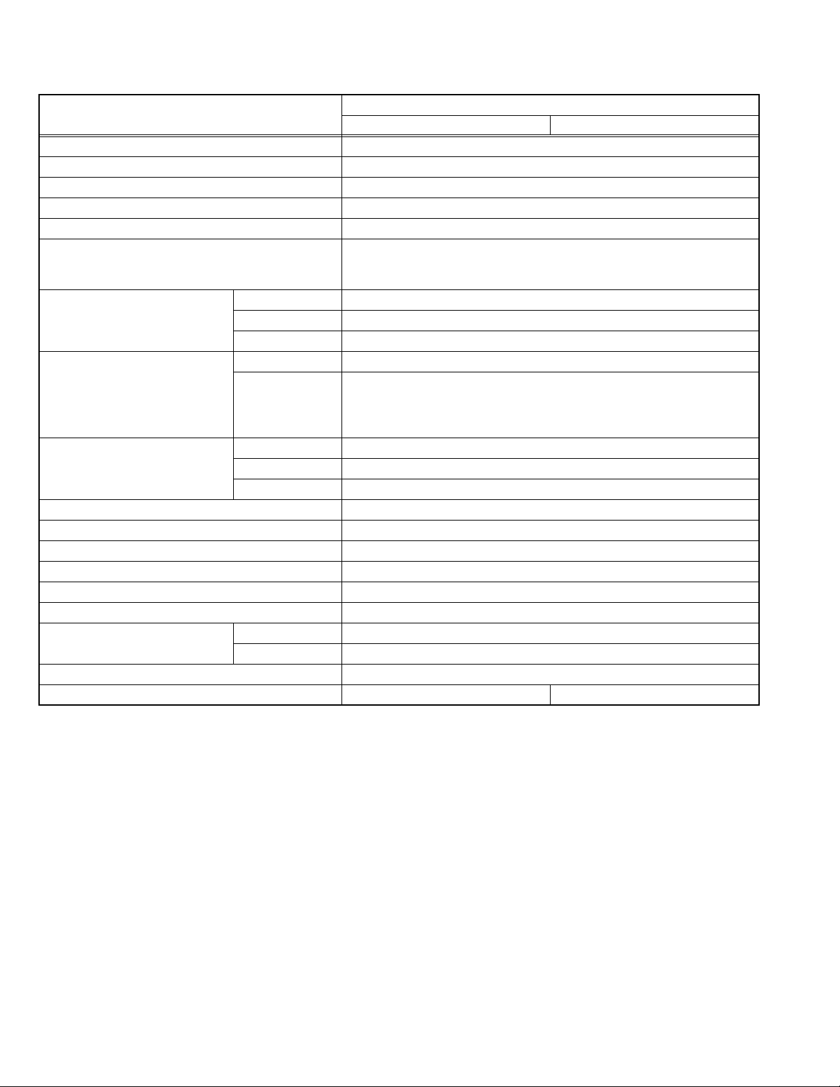
SPECIFICATION
Item
Dimensions ( W × H × D ) 74.6cm × 59.6cm × 48.0cm
Mass 31.5kg
TV RF System CCIR (B/G, D/K, I , L/L')
Colour System PAL / SECAM / NTSC (Only in EXT mode)
Stereo System A2 (B/G, D/K) / NICAM (B/G, I, D/K, L)
Teletext System FLOF (Fastext)
TOP (German system)
WST(World standard system)
Receiving Frequency VHF 47MHz ~ 470MHz
UHF 470MHz ~ 862MHz
French CATV 116MHz ~ 172MHz / 220MHz ~ 469MHz
Intermediate Frequency VIF 38.9MHz (B/G, D/K, I , L) / 33.95MHz (L')
SIF 33.4MHz (5.5MHz:B/G)
/ 32.9MHz (6.0MHz:I)
/ 32.4MHz (6.5MHz:L, D/K)
/ 40.45MHz (6.5MHz:L')
Colour Sub Carrier Frequency PAL 4.43MHz
SECAM 4.40625MHz / 4.25MHz
NTSC 3.58MHz / 4.43MHz
Power Input AC220V ~ AC240V, 50Hz
Power Consumption 69W (stand-by: 3W)
Aerial Input Terminal 75Ω unbalanced, coaxial
Picture Tube Visible size : 66cm (Measured diagonally)
Audio Power Output 7W + 7W (Rated)
EXT-1 / EXT-2 (Input / Output) 21-pin Euro connector (SCART socket × 2)
EXT-3 (Input) Video 1V(p-p), 75Ω (RCA pin jack × 1)
Audio (L/R) 500mV(rms) (-4dBs), High impedance (RCA pin jack × 2)
Headphone Jack 3.5mm stereo mini jack × 1
Remote Control Unit RM-C1514B (AA/R6 dry battery × 2) RM-C1514 (AA/R6 dry battery × 2)
Design & specifications are subject to change without notice.
AV-28NT4BU AV-28NT4SU
Contents
1-2 (No.YA082)
Page 3
SECTION 1
PRECAUTION
1.1 SAFETY PRECAUTIONS
(1) The design of this product contains special hardware,
many circuits and components specially for safety
purposes. For continued protection, no changes should be
made to the original design unless authorized in writing by
the manufacturer. Replacement parts must be identical to
those used in the original circuits. Service should be
performed by qualified personnel only.
(2) Alterations of the design or circuitry of the products should
not be made. Any design alterations or additions will void
the manufacturer's warranty and will further relieve the
manufacturer of responsibility for personal injury or
property damage resulting therefrom.
(3) Many electrical and mechanical parts in the products have
special safety-related characteristics. These
characteristics are often not evident from visual inspection
nor can the protection afforded by them necessarily be
obtained by using replacement components rated for
higher voltage, wattage, etc. Replacement parts which
have these special safety characteristics are identified in
the parts list of Service manual. Electrical components
having such features are identified by shading on the
schematics and by ( ) on the parts list in Service
manual. The use of a substitute replacement which does
not have the same safety characteristics as the
recommended replacement part shown in the parts list of
Service manual may cause shock, fire, or other hazards.
(4) Don't short between the LIVE side ground and
ISOLATED (NEUTRAL) side ground or EARTH side
ground when repairing.
Some model's power circuit is partly different in the GND.
The difference of the GND is shown by the LIVE : ( ) side
GND, the ISOLATED (NEUTRAL) : ( ) side GND and
EARTH : ( ) side GND.
Don't short between the LIVE side GND and ISOLATED
(NEUTRAL) side GND or EARTH side GND and never
measure the LIVE side GND and ISOLATED (NEUTRAL)
side GND or EARTH side GND at the same time with a
measuring apparatus (oscilloscope etc.). If above note will
not be kept, a fuse or any parts will be broken.
(5) If any repair has been made to the chassis, it is
recommended that the B1 setting should be checked or
adjusted (See B1 POWER SUPPLY check).
(6) The high voltage applied to the picture tube must conform
with that specified in Service manual. Excessive high
voltage can cause an increase in X-Ray emission, arcing
and possible component damage, therefore operation
under excessive high voltage conditions should be kept to
a minimum, or should be prevented. If severe arcing
occurs, remove the AC power immediately and determine
the cause by visual inspection (incorrect installation,
cracked or melted high voltage harness, poor soldering,
etc.). To maintain the proper minimum level of soft X-Ray
emission, components in the high voltage circuitry
including the picture tube must be the exact replacements
or alternatives approved by the manufacturer of the
complete product.
(7) Do not check high voltage by drawing an arc. Use a high
voltage meter or a high voltage probe with a VTVM.
Discharge the picture tube before attempting meter
connection, by connecting a clip lead to the ground frame
and connecting the other end of the lead through a 10kΩ
2W resistor to the anode button.
(8) When service is required, observe the original lead dress.
Extra precaution should be given to assure correct lead
dress in the high voltage circuit area. Where a short circuit
has occurred, those components that indicate evidence of
overheating should be replaced. Always use the
manufacturer's replacement components.
(9) Isolation Check (Safety for Electrical Shock Hazard)
After re-assembling the product, always perform an
isolation check on the exposed metal parts of the cabinet
(antenna terminals, video/audio input and output terminals,
Control knobs, metal cabinet, screw heads, earphone jack,
control shafts, etc.) to be sure the product is safe to operate
without danger of electrical shock.
a) Dielectric Strength Test
The isolation between the AC primary circuit and all metal
parts exposed to the user, particularly any exposed metal
part having a return path to the chassis should withstand a
voltage of 3000V AC (r.m.s.) for a period of one second. (.
. . . Withstand a voltage of 1100V AC (r.m.s.) to an
appliance rated up to 120V, and 3000V AC (r.m.s.) to an
appliance rated 200V or more, for a period of one second.)
This method of test requires a test equipment not generally
found in the service trade.
b) Leakage Current Check
Plug the AC line cord directly into the AC outlet (do not use
a line isolation transformer during this check.). Using a
"Leakage Current Tester", measure the leakage current
from each exposed metal part of the cabinet, particularly
any exposed metal part having a return path to the chassis,
to a known good earth ground (water pipe, etc.). Any
leakage current must not exceed 0.5mA AC (r.m.s.).
However, in tropical area, this must not exceed 0.2mA AC
(r.m.s.).
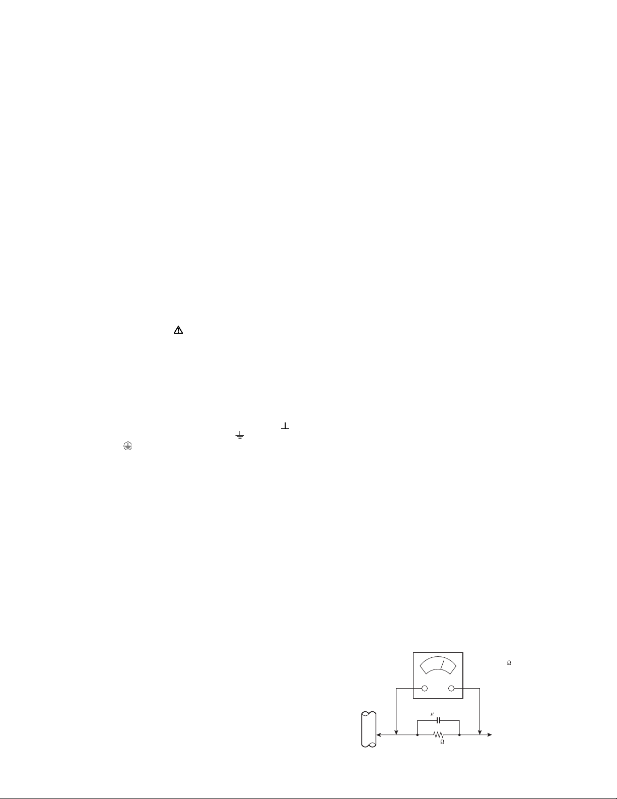
Alternate Check Method
Plug the AC line cord directly into the AC outlet (do not
use a line isolation transformer during this check.). Use
an AC voltmeter having 1000Ω per volt or more
sensitivity in the following manner. Connect a 1500Ω
10W resistor paralleled by a 0.15µF AC-type capacitor
between an exposed metal part and a known good earth
ground (water pipe, etc.). Measure the AC voltage
across the resistor with the AC voltmeter. Move the
resistor connection to each exposed metal part,
particularly any exposed metal part having a return path
to the chassis, and measure the AC voltage across the
resistor. Now, reverse the plug in the AC outlet and
repeat each measurement. Any voltage measured must
not exceed 0.75V AC (r.m.s.). This corresponds to
0.5mA AC (r.m.s.).
However, in tropical area, this must not exceed 0.3V AC
(r.m.s.). This corresponds to 0.2mA AC (r.m.s.).
AC VOLTMETER
(HAVING 1000 /V,
OR MORE SENSITIVITY)
0.15 F AC-TYPE
PLACE THIS PROBE
1500 10W
GOOD EARTH GROUND
ON EACH EXPOSED
ME TAL PAR T
(No.YA082)1-3
Page 4
SECTION 2
SPECIFIC SERVICE INSTRUCTIONS
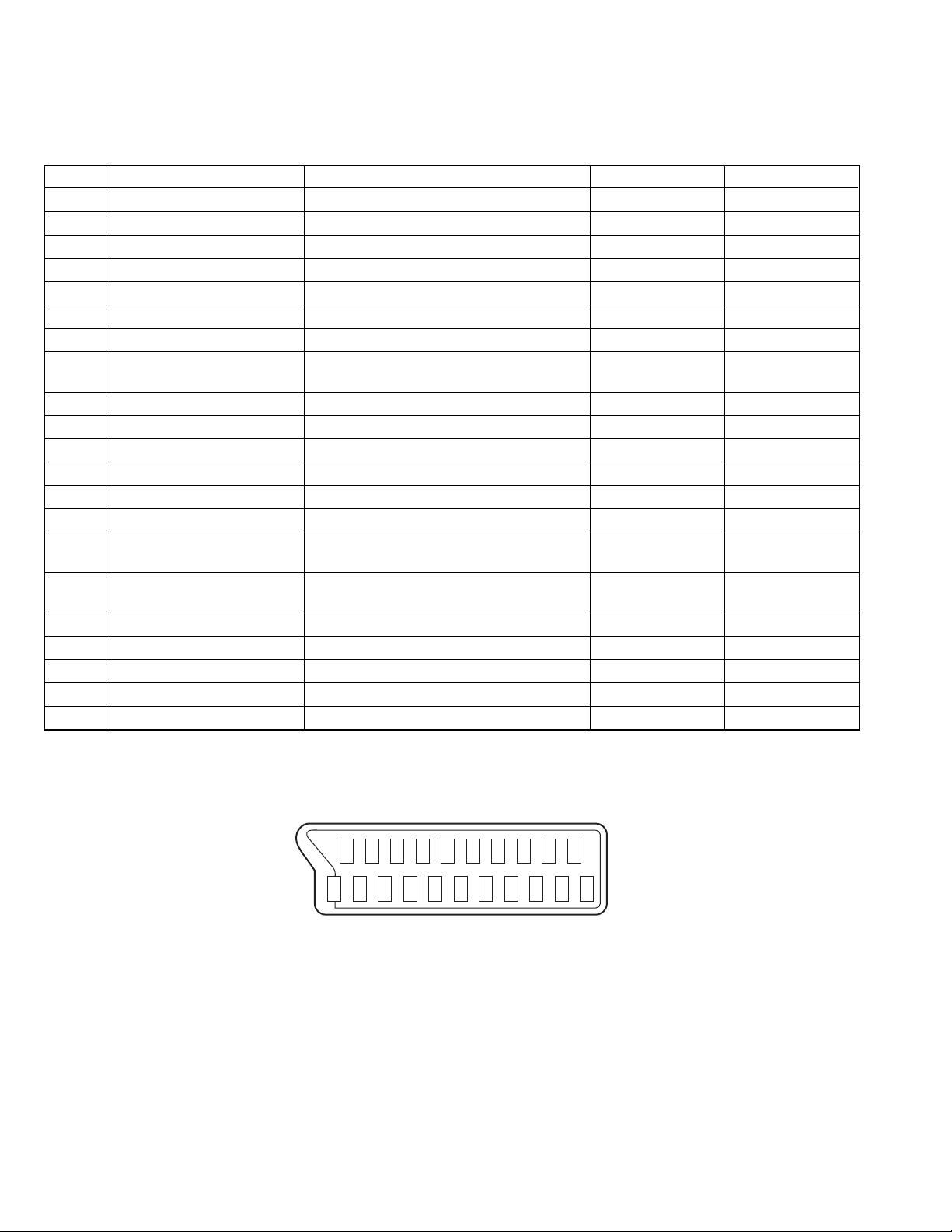
2.1 21-pin Euro connector (SCART) : EXT-1/EXT-2
Pin No. Signal designation Matching value EXT-1 EXT-2
1 AUDIO R output 500mV(rms) (Nominal), Low impedance Used (TV OUT) Used (LINE OUT)
2 AUDIO R input 500mV(rms) (Nominal), High impedance Used (R1) Used (R2)
3 AUDIO L output 500mV(rms) (Nominal), Low impedance Used (TV OUT) Used (LINE OUT)
4 AUDIO GND --- Used Used
5 GND (B) --- Used Used
6 AUDIO L input 500mV(rms) (Nominal), High impedance Used (L1) Used (L2)
7 B input 700mV
8 FUNCTION SW(SLOW SW) Low : 0V-3V
High : 8V-12V, High impedance
9 GND (G) --- Used NC
10 SCL / T-V LINK --- Not used NC
11 G input 700mV(B-W), 75 Ω Used NC
12 SDA --- Not used NC
13 GND (R) --- Used Used
14 GND (YS) --- Used Used
15 R / C input R : 700mV
C : 300mV
16 Ys input (FAST SW) Low : 0V-0.4V
High : 1V-3V, 75 Ω
17 GND (VIDEO output) --- Used Used
18 GND (VIDEO input) --- Used Used
19 VIDEO output 1V
20 VIDEO / Y input 1V
(P-P)
(P-P)
21 COMMON GND --- Used Used
, 75 Ω Used NC
(B-W)
Used NC
(B-W)
(P-P)
, 75 Ω
, 75 Ω
Used (R) Used (C)
Used NC
(Negative sync),75 Ω Used (TV OUT) Used (LINE OUT)
(Negative sync), 75 Ω Used Used
(P-P= Peak to Peak, B-W= Blanking to white peak)
[Pin assignment]
20 18 16 14 12 10 8 6 4 2
21 19 17 15 13 11 9 7 5 3 1
1-4 (No.YA082)
Page 5

SECTION 3
DISASSEMBLY
3.1 DISASSEMBLY PROCEDURE
3.1.1 REMOVING THE REAR COVER
(1) Unplug the power cord.
(2) Remove the 4 screws [A].
(3) Remove the 1 screw [B].
(4) Withdraw the REAR COVER toward you.
3.1.2 REMOVING THE MAIN PWB
• Remove the REAR COVER.
(1) Slightly raise the both sides of the chassis by hand and
Withdraw the MAIN PWB backward.
(If necessary, take off the wire clamp, connectors etc.)
3.1.3 REMOVING THE SIDE SPEAKER
• Remove the REAR COVER.
(1) Remove the 4 screws [C], attaching the SPEAKER.
(2) Follow the same steps when removing the other hand
SPEAKER.
3.1.4 CHECKING THE PW BOARD
• To check the back side of the PW Board.
(1) Pull out the MAIN PWB. (Refer to REMOVING THE MAIN
PWB).
(2) Erect the MAIN PWB vertically so that you can easily check
the back side of the PW Board.
CAUTION:
• When erecting the MAIN PWB, be careful so that there will
be no contacting with other PW Board.
• Before turning on power, make sure that the wire connector
is properly connected.
• When conducting a check with power supplied, be sure to
confirm that the CRT EARTH WIRE (BRAIDED ASS’Y) is
connected to the CRT SOCKET PWB.
3.1.5 WIRE CLAMPING AND CABLE TYING
• Be sure to clamp the wire.
• Never remove the cable tie used for tying the wires together.
• Should it be inadvertently removed, be sure to tie the wires
with a new cable tie.
FRONT CABINET
CRT EARTH WIRE
CRT SOCKET PWB
(With MAIN PWB)
MAIN PWB
REAR COVER
SPEAKER
FBT
C
(x4)
POWER CORD
B
(x1)
A
(x8)
(No.YA082)1-5
Page 6

3.2 REPLACEMENT OF MEMORY IC
3.2.1 MEMORY IC
This TV use memory IC. In the memory IC, there are memorized data for correctly operating the video and deflection circuits.
When replacing memory IC with a blanking memory IC, the set is automatically memorized following SERVICE MANU initial data.
3.2.2 SERVICE MENU ADJUSTMENT ITEMS
There are 22 SERVICE ADJUSTMENT ITEMS. After replacing
memory IC, automatically memorized following initial data.
No. Adjustment item
1HOR CEN
2 RED GAIN
3 GRN GAIN
4BLUE GAIN
5 RED BIAS
6 GRN BIAS
7 AGC LEVEL
8 G2-SCREEN
9OPTION 1
10 OPTION 2
11 AVL
12 PARABOLA
13 HOR WIDTH
14 CORNER T
15 CORNER B
16 HOR PARAL
17 V. LINEAR
18 V. SLOPE
19 EW TRAPEZ
20 S CORRECT
21 VERT CENT
22 VERT SIZE
3.2.3 FACTRY SETTING
3.2.3.1 FRONT BUTTON SETTING AND INITIAL SEETING
Item Value
MAIN POWER OFF(SUB POWER ON)
PR POSITION 01
INPUT MODE TV
LANGUAGE ENGLISH
3.2.3.2 USER MENU SETTING
Item Value
PICTURE
PICTURE SETTING NOMAL1
NOISE RED WEAK
SOUND
VOLUME 15
BALANCE Center
TREBLE Center
FEATURES
CHILD LOCK OFF
ZOOM AUTO 4:3
1-6 (No.YA082)
Page 7

3.3 REPLACEMENT OF CHIP COMPONENT
3.3.1 CAUTIONS
(1) Avoid heating for more than 3 seconds.
(2) Do not rub the electrodes and the resist parts of the pattern.
(3) When removing a chip part, melt the solder adequately.
(4) Do not reuse a chip part after removing it.
3.3.2 SOLDERING IRON
(1) Use a high insulation soldering iron with a thin pointed end of it.
(2) A 30w soldering iron is recommended for easily removing parts.
3.3.3 REPLACEMENT STEPS
1. How to remove Chip parts
2. How to install Chip parts
[Resistors, capacitors, etc.]
(1) As shown in the figure, push the part with tweezers and
alternately melt the solder at each end.
(2) Shift with the tweezers and remove the chip part.
[Transistors, diodes, variable resistors, etc.]
(1) Apply extra solder to each lead.
SOLDER
SOLDER
[Resistors, capacitors, etc.]
(1) Apply solder to the pattern as indicated in the figure.
(2) Grasp the chip part with tweezers and place it on the
solder. Then heat and melt the solder at both ends of the
chip part.
[Transistors, diodes, variable resistors, etc.]
(1) Apply solder to the pattern as indicated in the figure.
(2) Grasp the chip part with tweezers and place it on the
solder.
(3) First solder lead A as indicated in the figure.
(2) As shown in the figure, push the part with tweezers and
alternately melt the solder at each lead. Shift and remove
the chip part.
NOTE :
After removing the part, remove remaining solder from the
pattern.
A
B
C
(4) Then solder leads B and C.
A
B
C
(No.YA082)1-7
Page 8

SECTION 4
ADJUSTMENT
4.1 ADJUSTMENT PREPARATION
(1) There are 2 ways of adjusting this TV : One is with the REMOTE CONTROL UNIT and the other is the conventional method
using adjustment parts and components.
(2) Make sure that connection is correctly made AC to AC power source.
(3) Turn on the power of the TV and measuring instruments for warning up for at least 30 minutes before starting adjustments.
(4) If the receive or input signal is not specified, use the most appropriate signal for adjustment.
(5) Never touch the parts (such as variable resistors, transformers and condensers) not shown in the adjustment items of this service
adjustment.
4.2 MEASURING INSTRUMENT AND FIXTURES
(1) DC voltmeter (or digital voltmeter)
(2) Signal generator (Pattern generator : PAL / SECAM / NTSC)
(3) Remote control unit
4.3 BASIC OPERATION OF SERVICE MENU
4.3.1 TOOL OF SERVICE MENU OPERATION
Operate the SERVICE MENU with the REMOTE CONTROL
UNIT.
SERVICE Ver0.67 : 20/05/04
+00360
GRN GAIN
4.3.2 SERVICE ADJUSTMENT ITEMS
There are 22 adjustment items.
No. Adjustment item No. Adjustment item
1 HOR CEN 12 PARABOLA
2 RED GAIN 13 HOR WIDTH
3 GRN GAIN 14 CORNER T
4 BLUE GAIN 15 CORNER B
5 RED BIAS 16 HOR PARAL
6 GRN BIAS 17 V. LINEAR
7 AGC LEVEL 18 V. SLOPE
8 G2-SCREEN 19 EW TRAPEZ
9 OPTION 1 20 S CORRECT
10 OPTION 2 21 VERT CENT
11 AVL 22 VERT SIZE
4.3.3 HOW TO ENTER SERVICE MENU
(1) Press [ i ](Information) key and [ ](Muting) key same time
then enter SERVICE MENU.
(2) Adjust sharpness to minimum and exit all menus.
(3) Within 2 seconds press the key sequence [RED]-[GREEN]-
[MENU]key.
4.3.4 SELECTION OF ADJUSTMENT ITEMS
(1) Press [] / [] keys of the REMOTE CONTROL UNIT and
select adjustment item.
SERVICE MENU SCREEN
Muting key
To Enter
Information
key
Setting item
Setting value
132
465
798
0
ZOOM
PICTURE/OK
P
MENUAV
P
?
DVD
VCR
RM-C1514
TV
/
(Select item)
MENU
(To exit)
/
(Setting data)
4.3.5 SETTING OF ADJUSTMENT ITEMS
(1) Press [] / [] keys of the REMOTE CONTROL UNIT and
setting value of adjustment items.
4.3.6 HOW TO EXIT SERVICE MENU
(1) Press [MENU] key, then exit SERVICE MENU.
1-8 (No.YA082)
REMOTE CONTROLLER KEY
Page 9

4.4 ADJUSTMENT PROCEDURE
4.4.1 AGC
Item
AGC
adjustment
4.4.2 FOCUS ADJUSTMENT
Item
FOCUS
adjustment
Measuring
instrument
Signal
generator
Remote
control unit
Measuring
instrument
Signal
generator
Remote
control unit
FBT
Test point Adjustment part Description
AGC (1) Receive a colour bar pattern signal.
(2) Select < AGC >.
(3) Press the [OK] key and wait until AGC level stabilize
to the optimum value.
Test point Adjustment part Description
FOCUS VR
[On FBT]
(1) Receive a crosshatch signal.
(2) Adjust the FOCUS volume on the FBT to have the
best resolution on the screen.
FOCUS
4.4.3 SCREEN ADJUSTMENT
Item
SCREEN
adjustment
Measuring
instrument
Signal
generator
Remote
control unit
SCREEN
Test point Adjustment part Description
G2-SCREEN
SCREEN VR
[FBT]
(1) Receive a colour bar pattern signal.
(2) Select < G2-SCREEN >.
(3) Adjust the SCREEN VR on the FBT to bring the
cursor to central position.
(No.YA082)1-9
Page 10

4.4.4 WHITE BALANCE ADJUSTMENT
Item
WHITE
BALANCE
adjustment
4.4.5 DEFLECTION CIRCUIT ADJUSTMENT
Measuring
instrument
Signal
generator
Remote
control unit
Test point Adjustment part Description
RED BIAS
GRN BIAS
RED GAIN
GRN GAIN
BLUE GAIN
(1) Receive a black and white pattern signal (colour off).
(2) Select < RED BIAS >, < GRN BIAS > and adjust the
screen until the black portion in the screen becomes
black.
(3) Select < RED GAIN >, < GRN GAIN >, < BLUE GAIN >
and adjust the screen until the white portion in the
screen become white.
Item
VERTICAL
GEOMETORY
adjustment
Measuring
instrument
Signal
generator
Remote
control unit
Test point Adjustment part Description
V. LINEAR
S CORRECT
VERT SIZE
VERT CENT
(1) Receive a circle pattern signal.
(2 ) Select < V. LINEAR > (Veretical linearity), < S CORRECT >
(S-shape correction), < VERT SIZE > (Vertical size),
< VERT CENT > (Vertical center) respectively.
(3) Adjust to compensate for vertical distortion.
HORIZONTAL
POSITION
adjustment
1-10 (No.YA082)
Signal
generator
Remote
control unit
HOR CEN (1) Receive a circle pattern signal.
(2) Select < HOR CEN >(Horizontal center).
(3) Adjust to have the picture in the center of the screen.
Page 11

Item
HORIZONTAL
SIZE/
SIDE PIN
adjustment
Measuring
instrument
Signal
generator
Remote
control unit
Test point Adjustment part Description
PARABOLA
HOR WIDTH
CORNER
HOR PARAL
EW TRAPEZ
(1) Receive a crosshatch pattern signal.
(2) Select < PALABOLA >(Parabola), < HOR WIDTH >
(Horizontal width), < CORNER >(Top/bottom
corner), < HOR PARAL >(Horizontal parallel), < EW
TRAPEZ >(East/west trapezium.
(3) Adjust these items to compensate for geometrical
distortion.
PARABOLA
HOR WIDTH
CORNER
HOR PARAL
EW TRAPEZ
(No.YA082)1-11
Page 12

SECTION 5
TROUBLESHOOTING
This service manual does not describe TROUBLESHOOTING.
1-12 (No.YA082)
Page 13

Victor Company of Japan, Limited
AV & MULTIMEDIA COMPANY VIDEO DISPLAY CATEGORY 12, 3-chome, Moriya-cho, kanagawa-ku, Yokohama, kanagawa-prefecture, 221-8528, Japan
(No.YA082)
Printed in Japan
WPC
 Loading...