

Page 1
S
S
B
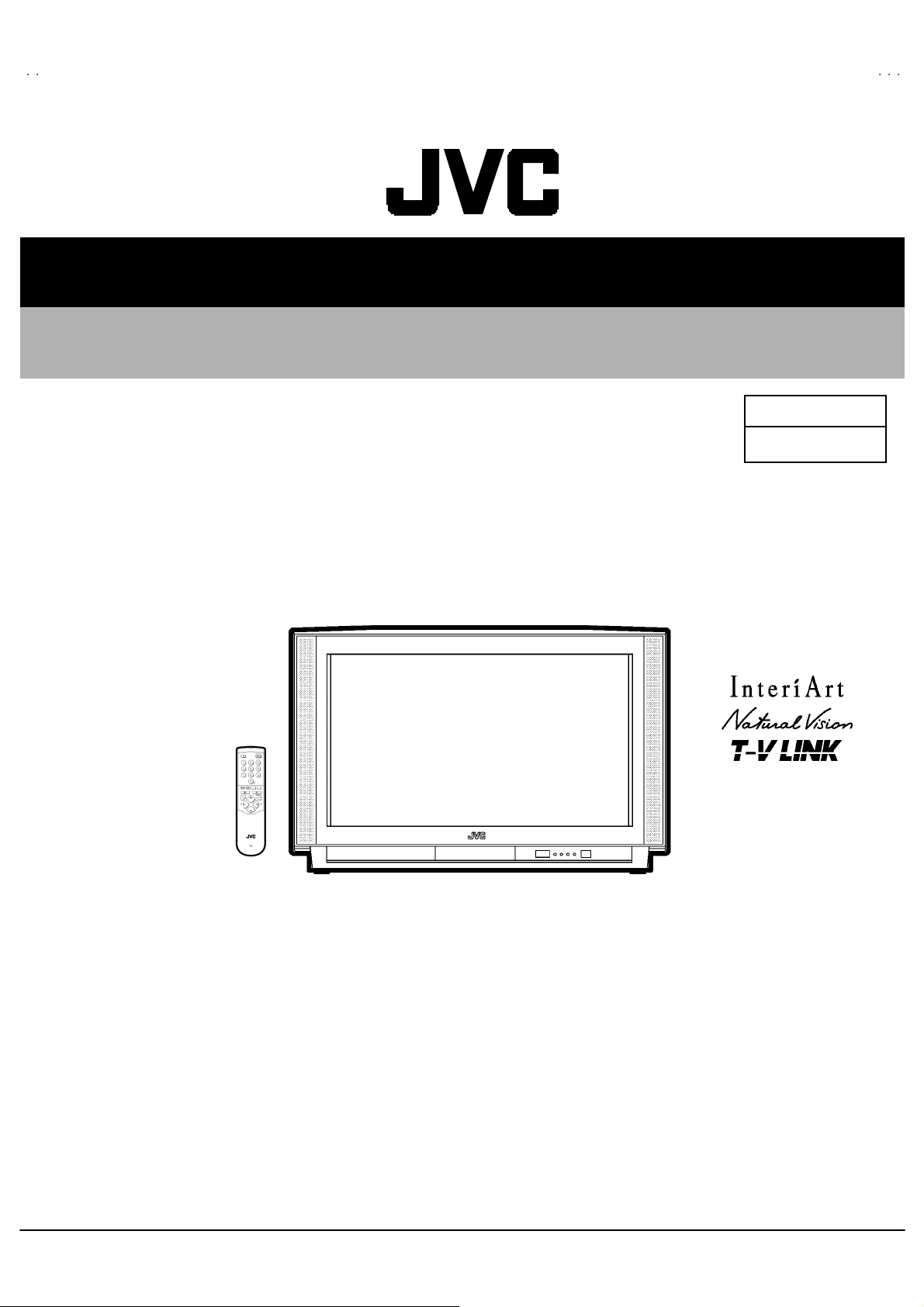
SERVICE MANUAL
COLOUR TELEVISION
AV32H20EUS
AV28H20EUS
AV32H20EU
AV28H20EU
AV28H20EU
BASIC CHASSIS
ⅡⅡⅡⅡ
MF
AV28H20EUB
CONTENTS
! SPECIFICATIONS ・・・・・・・・・・・・・・・・・・・・・・・・・・・・・・・・
!
SAFETY PRECAUT IONS
! FEATU RES・・・・・・・・・・・・・・・・・・・・・・・・・・・・・・・・
! MAIN DIFFERENCE LIST ・・・・・・・・・・・・・・・・・・・・・・・・・・・・・・・・
!
SPECIFIC SERVICE INSTRUCTIONS ・・・・・・・・・・・・・・・・・・・・・・・・・・・・・・・・
! SERVICE ADJUSTMENTS ・・・・・・・・・・・・・・・・・・・・・・・・・・・・・・・・
!
PARTS LIST
★
OPERATING INSTRUCTIONS
★
STAND ARD CIRCUIT DIAGRAM
・・・・・・・・・・・・・・・・・・・・・・・・・・・・・・・・・・・・・・・・・・・・・・・・・・・・・・・・・・・・・・・・
・・・・・・・・・・・・・・・・・・・・・・・・・・・・・・・・・・・・・・・・・・・・・・・・・・・・・・・・・・・・・・・・
・・・・・・・・・・・・・・・・・・・・・・・・・・・・・・・・・・・・・・・・・・・・・・・・・・・・・・・・・・・・・
・・・・・・・・・・・・・・・・・・・・・・・・・・・・・・・・・・・・・・・・・・・・・・・・・・・・・・・・・・・・・・・・
・・・・・・・・・・・・・・・・・・・・・・・・・・・・・・・・
・・・・・・・・・・・・・・・・・・・・・・・・・・・・・・・・・・・・・・・・・・・・・・・・・・・・・・・
・・・・・・・・・・・・・・・・・・・・・・・・・・・・・・・・・・・・・・・・・・・・・・・・・・・・・・・・・・・・・・・・
・・・・・・・・・・・・・・・・・・・・・・・・・・・・・・・・・・・
・・・・・・・・・・・・・・・・・・・・・・・・・・・・・・・・・・・・・・・・・・・・・・・・・・・・・・・・・・・・・・・・
・・・・・・・・・・・・・・・・・・・・・・・・・・・・・・・・・・・・・・・・・・・・・・・・・・・・・・・
・・・・・・・・・・・・・・・・・・・・・・・・・・・・・・・・・・・・・・・・・・・・・・・・・・・・・・・・・・・・・・・・
・・・・・・・・・・・・・・・・・・・・・・・・・・・・・・・・・・・・・・・・・・・・・
・・・・・・・・・・・・・・・・・・・・・・・・・・・・・・・・・・・・・・・・・・・・・・・・・・・・・・・・・・・・・・・・
・・・・・・・・・・・・・・・・・・・・・・・・・・・・・・・・・・・・・・・・・・・・・・・・・・・・・
・・・・・・・・・・・・・・・・・・・・・・・・・・・・・・・・・・・・・・・・・・・・・・・・・・・・・・・・・・・・・・・・
・・・・・・・・・・・・・・・・・・・・・・・・・・・・・・・・
・・・・・・・・・・・・・・・・・・・・・・・・・・・・・・・・・・・・・・・・・・・・・・・・・・・・・・・・・・・・・・・・
・・・・・・・・・・・・・・・・・・・・・・・・・・・・・・・・・・・・・・・・・・・・・・・・・・・・・・・・・・・・・・・・
・・・・・・・・・・・・・・・・・・・・・・・・・・・・・・・・
・・・・・・・・・・・・・・・・・・・・・・・・・・・・・・・・・・・・・・・・・・・・・・・・
・・・・・・・・・・・・・・・・・・・・・・・・・・・・・・・・・・・・・・・・・・・・・・・・・・・・・・・・・・・・・・・・
・・・・・・・・・・・・・・・・・・・・・・・・・・・・・ 2
・・・・・・・・・・・・・・・・・・・・・・・・・・・・・・・・・・・・・・・・・・・・・・・・・・・・・・・・・・
・・・・・・・・・・・・・・・・・・・・・・・
・・・・・・・・・・・・・・・・・・・・・・・・・・・・・・・・・・・・・・・・・・・・・・
・・・・・・・・・・・・・・・・・・・・・・・ 5
・・・・・・・・・・・・・・・・・・・・・・・・・・・・・・・・・・・・・・・・・・・・・・
・・・・・・・・・・・・・・・・・・・・・ 12
・・・・・・・・・・・・・・・・・・・・・・・・・・・・・・・・・・・・・・・・・・
・・・・・・・・・・・・・・・・・・・・・・・・・・・・・・・・・・・・
・・・・・・・・・・・・・・・・・・・・・・・・・・・・・・・・・・・・・・・・・・・・・・・・・・・・・・・・・・・・・・・・
・・・ 5
・・・・・・
・・・・・・・・・・・・・ 6
・・・・・・・・・・・・・・・・・・・・・・・・・・
・・・・・・・・・・・・・・・・
・・・・・・・・・・・・・・・・・・・・・・・・・・・・・・・・
4
31
2- 1
1
COPYRIGHT © 2002 VICTOR COMPANY OF JAPAN, LTD.
No.519 45
May 2002
Page 2
A
V32H20EUS
A
A
V28H20EUS
V28H20EUB
SPECIFICATIONS
Item
Dimensions ( W××××H××××D ) 85 5m m ×5 50mm×5 68mm 78 0m m ×5 09mm ×499m m
Mass 53 .6 kg 40 .2 kg
TV RF System
Colour Syst em PA L / SEC A M / N TSC (Only in EXT mode)
Stere o Sy st em A2 (B /G,D/K )/ NICAM ( B/G, I,D /K,L )
Teletext System FLOF (Fastext)
Receiving Frequency
French CATV 116MHz ~ 1 72MHz / 22 0MHz ~ 469MHz
Intermediate Fr equency
VIF Carrier 38.9MHz ( B/G , I ,L)/ 33.95 MHz (L’)
SIF Carrier 33.4MHz ( 5 .5MHz :B/ G) / 32.9MHz ( 6.0MHz:I ) / 32.4MHz ( 6. 5MHz:L , D/K) / 40.4 5MHz (6.5MHz:L ’)
Colour Sub Carrier Freq.
SE CAM 4.40625MHz/4.25MHz
Power Input 220 – 240 V AC, 50Hz 220 – 240 V AC, 50Hz
Power Consumption 187W(Max) / 138W(Avg), standby : 2.6W 178W(Max) / 125W(Avg), standby : 2.6W
Aerial Input Term
Pictur e Tube Visi bl e siz e : 7 6cm, M eas ured dia gon ally Visi bl e size : 66cm , Meas ured dia gonal ly
Hi gh Vo l t ag e
CCIR (B/G ,D/K,I ,L, L ’)
TOP (German syst em)
WST(W orld Stan dard system)
VHF 47 MHz ~ 47 0M Hz
UHF
470MHz ~ 8 62MHz
PAL 4.43MHz
NT S C 3.58MHz / 4.43MHz
75Ωun ba l anc ed, C oaxial
1kV
+
-1. 5kV
31.0kV (at zero beam current)
AV 32 H 20 EU S AV 28 H 20 EU S / AV28 H2 0E UB
Content
Speake r (16c m×4c m) ov al typ e ×2
Au dio Output 7.5 W + 7.5 W
EX T-1/EXT - 2/E XT-3
(Input / Output)
S / Video
EXT-4 (Input) Video
Au di o (L /R )
S / Video
AUDIO OUT (Vari able)
Headphone jack
Remote Control Unit RM-C 54 H (AAA/R0 3 dr y batte ry×2) : (A V32H 20 EUS, A V28H20 EU S)
21 -p i n E uro c onnec to r
(SCART socket)
p-p
Y : 1V
C : 0.3V
1V p- p 7 5Ω( RCA pin jack )
50 0m Vr ms( -4dB s ), H i gh Im pe dance ( RCA pin jack )
Y : 1V
C : 0.3V
0~1Vrm s , Low Im p ed ance
(RCA pi n ja ck×2)
St ereo min i jac k (φ3.5mm )
RM-C 50( A AA/R0 3 d r y bat tery×2) : (AV28H20EUB)
POSITIVE (Negative sync Provided, when terminated with 75Ω)
p-p
(Burst signal, when terminated with 75Ω)
p-p
POSITIVE (Negative sync Provided, when terminated with 75Ω)
p-p
(Burst signal, when terminated with 75Ω)
De sign & speci f icatio ns ar e su bje ct to cha ng e wi thout no t ice.
2
No.51945
Page 3
A
V32H20EUS
A
A
V28H20EUS
V28H20EUB
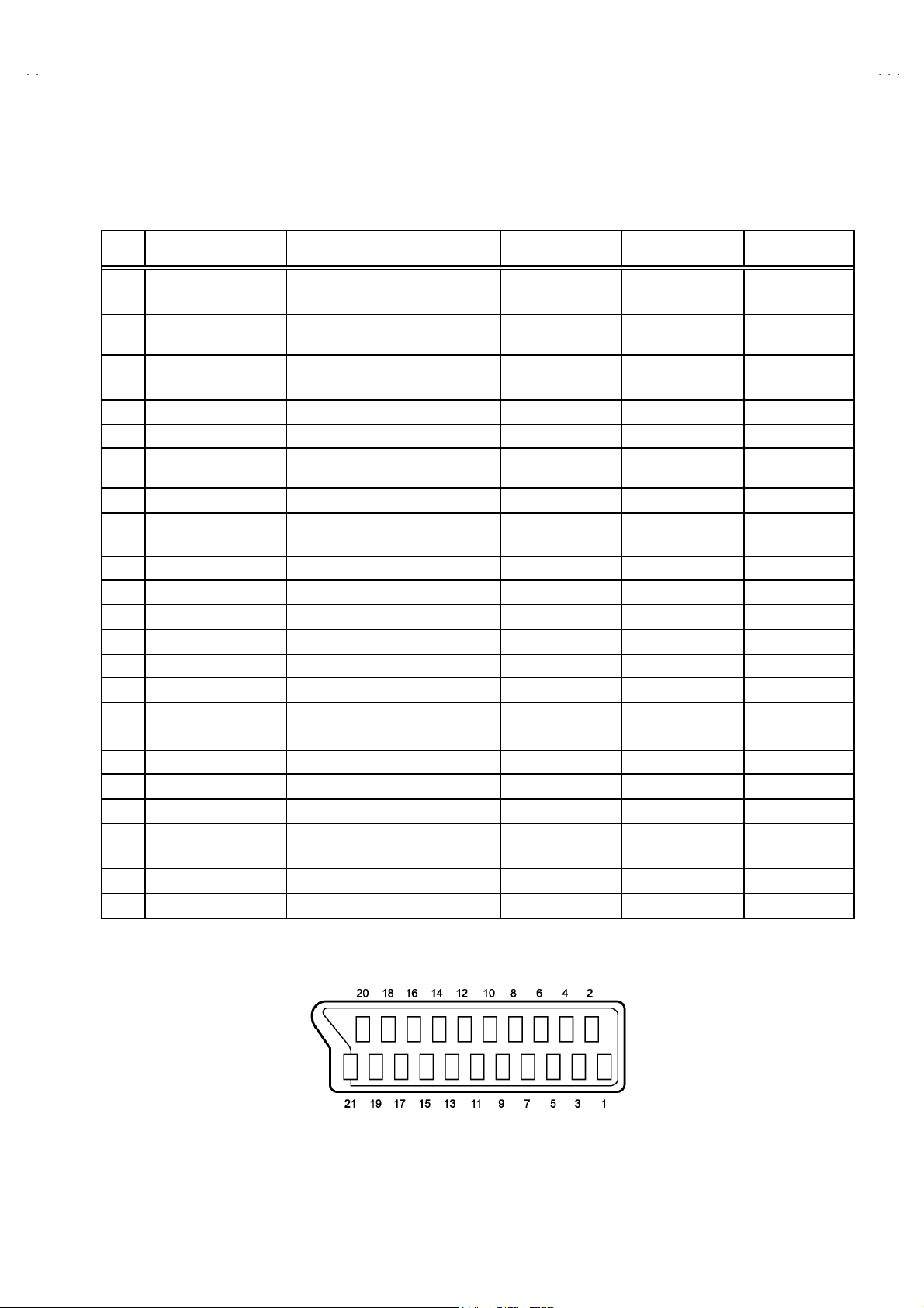
■■■■21-pin Euro connector (SCART socket) : EXT-1 / EXT-2 / EXT-3
(P-P= Peak to Peak, B-W= Blanking to white peak)
Pin
Signal Designation Matching Value EXT-1 EXT-2 EXT-3
No .
1 AUDIO R o utput 50 0m Vr ms(Nomina l) ,
Low impedance
2 AUDIO R i n put 50 0m Vr ms(Nomina l) ,
High i m pe danc e
3 AUDIO L outp ut 50 0m Vr ms(Nomina l),
Low impedance
4 AUDIO GN D ○○○
5 GND (B)
6 AUDIO L input 500mVrms(Nominal),
High i m pe danc e
7B input 700mV
8 FUNCTION SW
(SLOW SW)
9 GND (G)
10 SCL3 NC ○ NC
11 G in put 70 0mV
12 SDA3 NC ○ NC
13 GND (R)
14 GND (YS) ○ NC NC
15 R / C input R : 700mV
16 Ys i n put
17 GND(VIDEO output) ○○○
18 GND(VIDEO input) ○○○
19 VID EO outpu t 1V
20 VIDEO / Y inp ut 1V
21 COMMON GN D ○○○
Low : 0-3V, High : 8-12V, High
impedance
C : 300mV
Low : 0 - 0.4, High : 1 - 3V, 75Ω○
, 75Ω○○NC
B- W
, 75Ω○○NC
B- W
, 75Ω
B- W
, 75Ω
P- P
(Nega ti ve g oi n g s ync ), 75Ω○
P- P
(Nega ti ve g oi n g s ync ), 75Ω○ ○ ○
P- P
○
(TV OUT)
○○○
○
(TV OUT)
○○○
○○○
○○○
○○○
○○○
○
(only R)
(TV)
○
(LINE OUT)
○
(LINE OUT)
○
NC NC
○
(LINE OUT)
NC
NC
○
(only C )
NC
[Pin assignment]
No.51945
3
Page 4
A
V32H20EUS
A
A
V28H20EUS
V28H20EUB
SAFETY PRECAUTIONS
1. T he des i gn of th is pr od uct con ta ins speci al har d ware , many
circuit s and components specially for saf ety purposes. For
con tinu ed pr ot ecti on , n o chan g es sh ould b e ma de to the o rig i nal
d esign un less a uth or ized in writi n g by th e manu fac t urer .
Replacem ent p arts m ust b e i d entic al to thos e u sed in th e or i gi n al
ci rcu its. S er v i ce sho ul d b e p er for m ed by qu alif ied p ers on nel
on ly.
2. Alte r ation s of the desi g n or circui tr y of t he prod ucts s h oul d not be
made. Any design alterations or additions will void the
manu fac t urer 's warra nt y and will f urth er r el i eve t he ma nufac tu rer
of r esp onsib ili ty for per s o na l injury or pr operty d am ag e res ul t ing
th erefr om.
3. M an y el ectr i cal an d mech anic a l p ar ts i n th e pr od uc ts ha v e
special safety-related chara cteristics. T hese characteristics are
oft en no t e vi den t f r om v i sua l insp ecti on nor ca n t he pro tect io n
aff orde d by th em nece ssarily be ob tain ed b y u s in g r ep l ac em en t
com po nents rated for hig he r vo l tag e, watt age, etc . R ep lac em en t
p arts whic h have th ese sp ecial s afet y ch ar act erist ics ar e
ide ntified in the parts list of Ser vic e manua l. El ectric al
components having such features are ide ntified by shading
on the sche mat ic s and b y (
manual. The us e of a sub sti tu te r ep lac em en t which do es n ot
h ave th e sam e s af ety c h ar ac t erist ics as t he reco mmen ded
replac ement par t sh ow n i n th e parts list of Ser v i ce man ual m ay
cause shock, fire, or other hazards.
!!!!
) on the parts list in Service
4. Don't shor t between the LIVE s ide ground and ISOLATED
(NE UTRAL) side ground or EARTH side ground when
repairing.
Some model's power circuit is partly different in the GND. The
diff erenc e of th e G ND i s sho wn b y th e LIVE : (") side GND, the
ISO LATE D(N EU TR AL) : (#) si de G ND and EART H : ($) side
GND. D o n't sh ort b et ween th e LIV E s i d e GND an d
ISO LATE D(N EU TR AL) si de GND or EAR TH side GN D an d
n ever mea sure w it h a mea sur i ng a ppa r atus ( osci l lo scop e etc.)
th e LI VE sid e GN D an d IS OLA TED(NE UTRAL ) s ide G ND or
EARTH sid e GND at the s ame time.
If above not e will not be kept, a fuse or any parts will be broken.
5. If any repair has been made to the chassis, it is recommended
th at t he B1 set ting shou l d b e c h ec ked or adju ste d ( Se e
ADJUSTM ENT OF B 1 POW E R SUPPLY).
6. The hi gh vol ta ge app lie d t o th e pi ctu r e tu be mu s t c on form with
th at sp ecifi ed i n S ervi ce man ual . E xc essi ve h i gh volt ag e c a n
cau se an i ncr e ase i n X- R ay em iss i on , arci ng an d possi b le
component damage, therefore operation under excessive high
voltage conditions should be kept to a minimum, or should be
preve nt ed. If s ever e arc ing occur s, r emov e t he AC power
immed iate l y and de ter m i ne th e ca us e b y vi sua l insp ec t ion
(incor r ec t in stal lat i on, cr ac ke d or melte d hi gh vo lt age harn ess,
p oor so ld er ing, et c.) . T o m ai nt ain the prope r mi n imu m le vel of
sof t X- R ay em iss i on, c omp on en ts i n th e hi gh voltag e c i r cuitr y
incl ud i ng t he pict ure tu be must be t he e xact r ep lacem e nts or
alte rn at ives ap pr ove d b y th e manuf ac t urer of th e c omplet e
prod uct.
7. Do not c hec k hi gh volt ag e by dr aw i ng an arc. Use a hi gh volt age
meter or a hig h v oltag e pr ob e wit h a V TVM . Discha rg e th e
picture tube before attempting meter connection, by connecting
a cl i p le ad to th e gr ou nd f rame and conn ecti n g th e oth er end of
the lead through a 10kΩ 2W resi sto r to the anod e butt on .
8. When se r vic e is r equ ire d, ob serve th e or i gina l lea d dr ess. E x tr a
prec aut i on sh ou ld b e given t o assur e cor r ect l ea d dress in th e
high vol tag e circui t a rea. W her e a s hor t c i r cuit h as occ u rr e d,
th ose co mpon ent s tha t indica te evide nce of ove r hea ting should
b e r e place d. A lways u s e th e manuf act ur er 's rep lacem ent
components.
9. Isol ation Check
(1) Dielectric Strength Test
(2) Leakage Current Check
(Safety for Electrical Shock Hazard)
Af ter r e- ass embl in g th e p r odu ct, always per f orm an i solat io n
ch eck on the expo s ed me tal p ar ts of t he cabin et ( a nte nn a
ter m i na ls, vid eo /au dio i npu t and outpu t t ermi n al s, C on trol kn obs,
metal cabin et, sc r ew he ad s, ea rph one j ack, con tr ol s haf ts, etc.)
to be su re th e p r odu ct is s af e t o o pe rate with ou t d an ger of
elect rical shoc k.
The iso lation be tw een the AC pr im a ry ci rcu it an d al l me tal p arts
exp osed t o the us er, p ar ticular ly an y e xpos ed met al p art having a
retu rn p ath to t he c hass is sho uld withs tan d a vol t age of 3000 V
AC (r.m. s.) for a period of one sec ond.
(. . . . W it hstan d a v o lt age of 110 0V A C (r .m. s.) t o an ap plianc e
rate d up to 12 0V , an d 3 00 0V AC ( r.m. s.) to an ap pl i an c e r at ed
200V or more, for a period of one second.)
This meth od of test r equi res a test equipment n ot g enerall y fou nd
in t he serv ic e trad e.
Plug th e AC l in e c ord d irect ly into the A C ou tlet ( d o not use a lin e
isol ati o n transf orm er du r ing this ch eck.). U sin g a " Lea kag e
Current T este r", me as ur e th e l ea k ag e cu rr e nt f rom eac h ex p os ed
metal p ar t of the cabine t, p art icu lar ly any e x pos ed me tal p art
h aving a re turn pa th to the ch assis , to a kn own go od ea rt h
grou nd (w a ter pip e, e tc.). An y l eaka ge c ur r en t must n ot e xceed
0.5mA AC (r.m.s.).
Howev e r, in trop ic al ar ea , th is mu st no t ex ce ed 0.2 mA AC
(r.m.s.).
""""
Alte rn at e Che ck M et hod
Plug th e AC l in e c ord d irect ly into the A C ou tlet ( d o not use a lin e
isol ati o n tran sfor m er dur i ng this c he c k.). Use an AC vo lt meter
h aving 1 00 0 oh ms pe r vol t or mor e s ens it i vity i n th e fo llowi ng
mann er . C on nec t a 1 50 0Ω 10W res ist or par a lle le d b y a 0 .1 5µF
AC-type c apa cit or bet ween an expo sed met al pa rt and a kno wn
g ood e ar th gr o und (water pi pe , etc.) . M eas ur e th e A C volt ag e
acr os s th e res ist or wi th th e AC vo l tm eter. Move th e r es i stor
con nec tion to e ach exp ose d me tal part, p art i cularly any exp osed
metal p ar t havi n g a r etu rn pat h to the ch assis, and m easu r e th e
AC vol tag e ac ros s the res ist or. No w , re v er se th e pl u g in th e AC
ou tl et and re pe at eac h mea suremen t. An y vol t ag e me asu re d
must no t e xc eed 0 .7 5V AC (r.m. s.) . This c orre spo nds to 0 .5mA
AC (r.m. s.).
Howeve r, in tropica l area, this must n ot exce ed 0 .3V AC ( r .m.s.).
This corresponds to 0.2mA AC (r.m.s.).
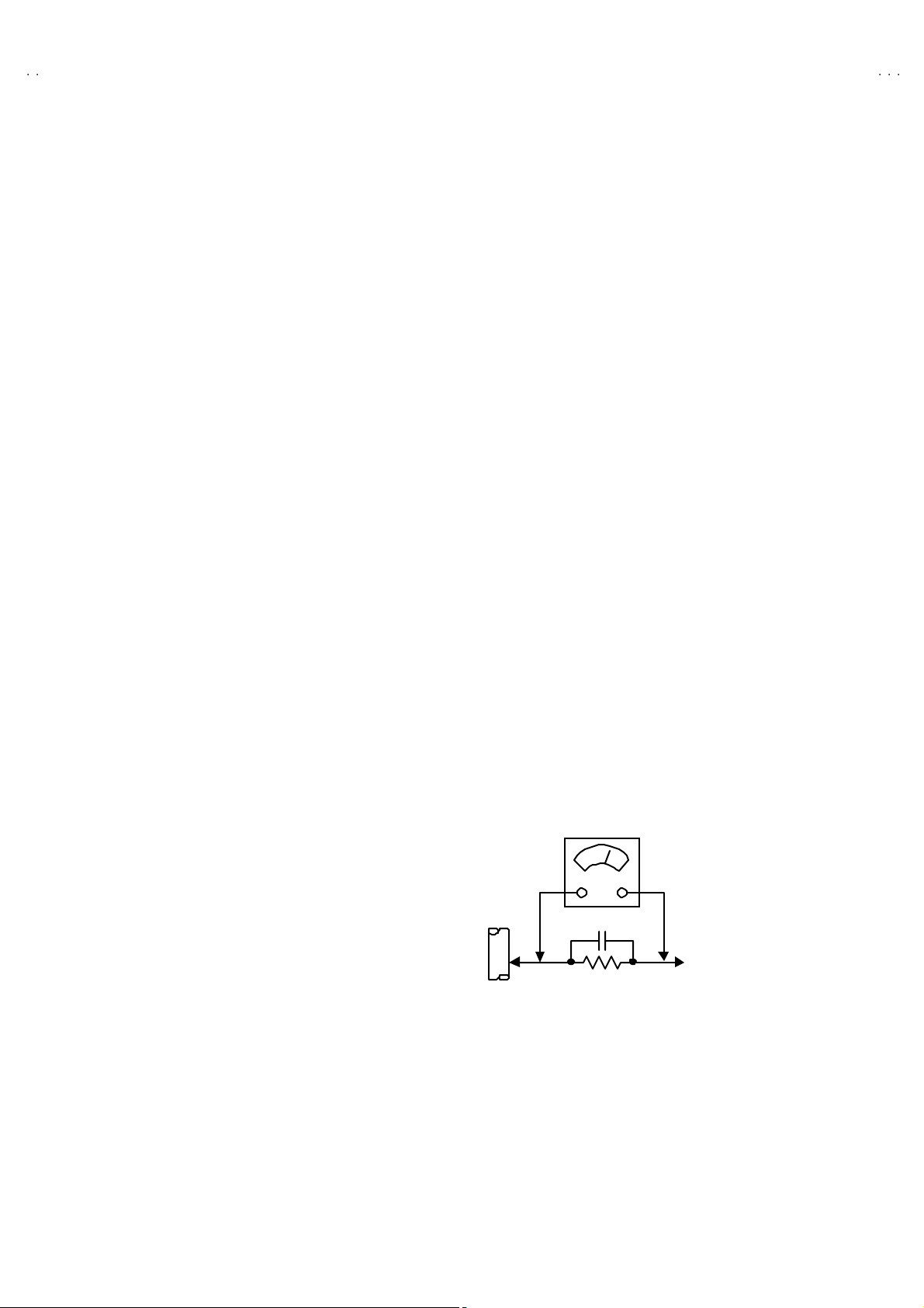
AC VOLT MET ER
(HAVING 1000 Ω /V,
OR MOR E SENSIT IVITY)
0.15μF AC-T YPE
PLACE THIS PROBE
1500 Ω 10W
GOOD EARTH GROUND
ON E A C H EX PO SE D
ME T AL PA RT
4
No.51945
Page 5
A
A
A
FEATURES
V32H20EUS
V28H20EUS
V28H20EUB
"
New c hassi s d esign ena bl e us e of an inte rac tive on screen
control.
"
The TELETEXT SYSTEM has a built-in FASTEXT (UK system),
TOP (Germ an syst em) and W ST (world stan dard system)
system.
"
Be caus e th is TV un i t corr esp on ds t o m ultipl e x br oa dca s t, u ser s
can enjoy music programs and sporting events with live realism.
In ad dition , BI LIN GU AL pro gr am s can be h ear d in th ei r or i g in al
language.
TV EXT-1 EXT-3
EXT-2
"
Users can make VCR dubbing of picture and sound by controlling
th e AV sel ec tor to s e le c t an o pti o na l so urc e at th e EXT- 2 outp ut
sh own i n figu re.
EXT-4
MAIN DIFFERENCE LIST
Model Name
!
Par t Name
MAIN PWB ASSY SMF-1401A-U2 SMF-1402A-U2
POWER & DEF PWB ASSY SMF-2401A-U2 SMF-2402A-U2
CRT SOCKET PWB ASSY SMF-3401A-U2 SMF-3402A-U2
FRONT C ONT ROL PW B ASSY SMF- 84 01A- U2 SMF- 8402 A- U2
!
FRONT C AB I NET A SS Y LC10 376- 020A -U LC 1066 2-02 3A-U LC 1066 2-02 4A-U
!
DOOR LC 20 265- 017A -U LC 20 265- 024A -U
!
POWE R KNOB LC 30 578- 007B-U LC 3057 8- 00 4A -U
!
REAR COVER LC10378-004B-U LC10664-003B-U LC10664-001E-U
JV C MA RK LC 40 354- 003A-C LC 4035 4- 00 1C- C
!
RATING LABEL LC20379-027A-U LC20379-026A-U LC20379-025A-U
AV32 H20E US AV28 H2 0E US AV28 H20E UB
EURO LABEL AEM 10 52-0 63 -E AEM 1052 -064 -E AEM 10 52-0 96 -E
REMOTE CONTROL UNIT RM -C54H-1C RM-C50-1C
No.51945
5
Page 6
A
V32H20EUS
A
A
V28H20EUS
V28H20EUB
SPECIFIC SERVICE INSTRUCTIONS
DISASSEMBLY PROCEDURE
REMOVING THE REAR COVER
1. Unplug t he po we r c ord.
2. Rem ov e t he 12 (28 ” m od el s), 13 ( 32 ” m ode l) scr ews ma r ked A
as s hown in t he F i g. 1.
3. Withdr a w t he r ear co ver to wa rd you .
REMOVING THE CHASSIS
"
After removing the rear cover.
1. Sli ght ly rai se th e bo th si de s of the c hass i s by h and and r e mo ve
th e two c l aws u nd er th e b oth sid es of the chass i s fr om t he fro nt
cab inet .
2. Withdr a w t he chass is backw a rd .
(If necessary, take off the wire clamp, co nnectors etc.)
REMOVING THE SPEAKER
"
After removing the rear cover.
1. Remove t he 2 scr ew s m ar ked B, and r em ove th e sp eake r hold er
as s hown in Fi g. 1.
NOTE : When r em oving t he sc r ew s marked B of t he sp eake r
remove t he lo w er side sc r ew fi r s t, an d t hen remove th e
up per one .
2. Remove the 2 screws C a ttac hing th e sp eak er.
3. Fol l ow th e s am e st eps wh en rem oving the oth er ha nd spe ake r.
REMOVING THE AV TERMINAL BOARD
" After removing the rear cover.
1. Remove the 3 scr ew s m ar ked D as shown in t he F ig. 1 .
2. Remove the 2 cla ws mark ed E under the CHASSIS as shown in
Fig. 2.
3. Remove the AV TERMINAL BOARD slightly in the direction of
arrow F as shown in Fig. 2.
REMOVING THE POWER & DEF PWB
" After removing the rear cover.
"
After removing the rear CHASSIS.
1. Remove the 3 scr ew s marked G .
2. Rem ove the PO WER & DEF PW B.
CHECKIN G THE PW BOARD
To c h ec k the back s i de of th e PW B oard.
1) Pull out the ch assis. ( Refer to REMOVIN G TH E CH AS SIS ).
2) Erect the c hassis vertically so that you c an easily check the
b ack side of the PW B oard.
[CAUTION]
"
When erecting the chassis, be careful s o that there will be no
con tact ing with ot her PW Boar d.
"
Be fore tur n ing on po wer, ma ke sur e tha t the wire co nnecto r is
prop er l y con nected .
"
W hen co ndu cti ng a c h ec k wi th p ow er su pplied , b e sure to c onfir m
th at t he CRT E AR T H WI RE (B RAIDED AS S’Y) is co nne c ted t o
th e C R T SOC KE T PW b oard.
WIRE CLAMPIN G AND CABLE T Y ING
1. Be sur e t o clamp th e wire.
2. Never r em ove th e c able tie use d f or tying th e wires to ge the r.
Should it be inadver t ent ly removed , b e sure to tie th e wires wi th
a n ew c able tie.
AV SW PWB
AV TERMINAL
BOARD
E
E
Fig . 2
6
No.51945
Page 7
A
A
A
FRONT CABINET
(
)
(×3)
(
)
(
)
FRONT
C ONT RO L
PWB(1/2 )
CRT
SOCKET
PWB
FRONT
C ONT RO L
PWB(2/2 )
V32H20EUS
V28H20EUS
V28H20EUB
B
×
2
SP EAKER
C
G
×
3
×
2
MICOM PWB
100Hz PWB
POWER & DEF.
PWB
CLAW
REAR COVER
AV TERMINAL
BOARD
AV SW
PWB
CLAW
MAIN
PWB
CHASSIS
D
POWER CORD
Thi s expl o de d vi ew des cribe s ab out
AV 28H2 0EUS / AV28 H20EUB.
Alth ou gh AV 32 H 20E US are sl i ght ly
diff erent from t his f ig ur e, you c an use
th e e xpl od ed vi ew f or disass em bl i ng
th e A V32 H 20E U S in sam e ste p as
AV 28H2 0EUS / AV28 H20E UB.
(×12 : 28” mod el s)
A
(×13 : 32” mod el )
Fig . 1
No.51945
7
Page 8
A
V32H20EUS
A
A
V28H20EUS
V28H20EUB
REMOVING THE CRT
∗
Replacem en t of th e CRT s ho ul d be p er for m ed b y 2 or mor e
p ers ons.
• After removing the cover, chassis etc.,
1. Putti ng the CRT chan ge table o n sof t cl oth , th e C R T cha nge ta ble
sh ould al so b e c over e d w i th s uch soft clot h (s ho wn i n Fig. 3) .
2. W hile kee pin g the s urfac e of C RT down , mou nt the TV s et o n t he
CRT change table balanced will as shown in Fig.4.
3. R em ov e 4 sc rews mark e d by arro ws with a box ty p e scr e w dri ver
as s hown in Fig. 4.
• Si nc e the cab i net will drop w h en scr ews h ave b een rem o ve d, be
sure t o su pp ort t he cabinet with hands.
4. After 4 screws have been removed, put the cabinet slowly on
cloth (At th is time, be ca refully so as not to damage th e front
sur fac e of th e c abin et) s h ow n i n Fig.5 .
• The CRT sh ould b e ass embled accor di n g to th e o pp osi te
sequence of its dismounting steps.
∗
The C RT cha ng e t able sh ould pr ef erab ly b e smaller that th e CRT
sur fac e, and its h ei gh t be abo ut 35c m.
CRT CHANGE TABLE
AP PROX.
35 cm
CLOTH
Fig. 3
CRT
CRT
CHANGE
TABLE
BOX
TYPE
SCREW
DRI VER
CABINET
Fig. 4
CRT
CRT
CHANGE TABLE
Fig. 5
8
No. 51945
Page 9
A
A
A
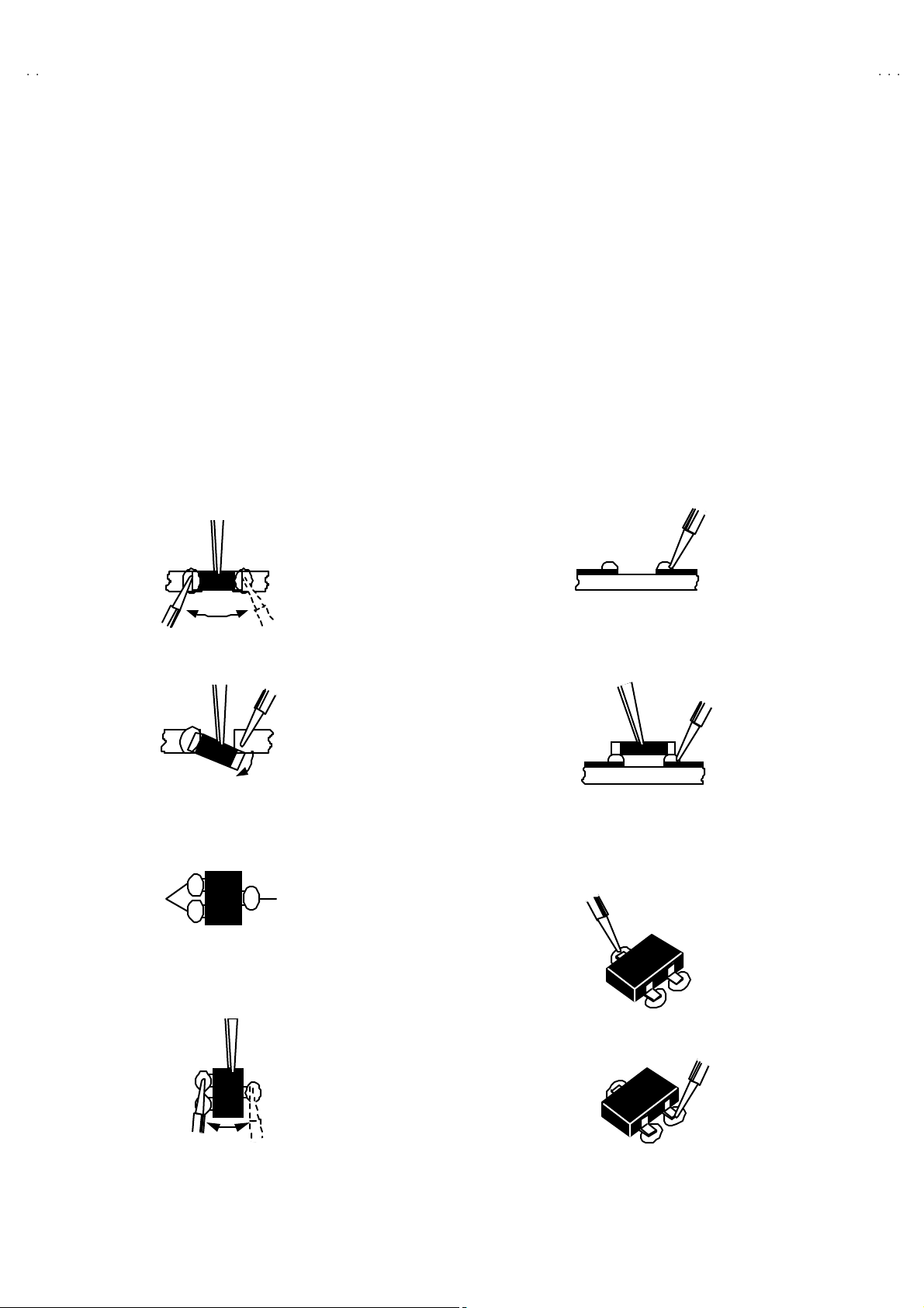
REPLACEMENT OF CHIP COMPONENT
! CAUTIONS
1. Avoid heating for more than 3 seconds.
2. Do n ot ru b the elect ro des an d the r esist p arts of the p att ern.
3. W hen r em oving a chip par t, mel t th e s older ad equately.
4. Do n ot reuse a ch ip p ar t afte r re mo v ing it .
! SOLDERING IRON
1. Use a hig h i ns ulatio n s ol der i ng i r on with a thi n poin ted e nd of it.
2. A 3 0 w s older i ng iron is r ec ommend ed for easily r em oving p ar ts.
!
REPLACEMENT STEPS
1. How to remove Chip parts
####
Resi st o rs, capacitors , etc
(1) As sh own in the f ig ur e, pu sh th e pa rt w ith tw ee zer s and
alte rn at ely melt the s ol de r at eac h end.
(2) Sh if t with tweeze rs and r em ove th e c h i p p art.
#### Tran s istor s, diodes , variabl e r esistor s, etc
(1) Ap pl y e xt ra so ld er to eac h le ad .
SOLDE R SOLDE R
V32H20EUS
V28H20EUS
V28H20EUB
2. How to install Chip parts
####
Resi st o rs, ca pacit ors , etc
(1) Apply sold er to the pattern as indic ate d in the figure.
(2) Gr asp the c h i p p art with tw ee zer s and pl ac e it on th e s old er.
The n hea t and me lt th e so lder a t both ends of t he chi p part.
#### Tran s istor s, diodes , variabl e r esistor s, etc
(1) Apply sold er to the pattern as indic ate d in the figure.
(2) Gr asp th e ch ip p art wit h t we ezers an d pl ac e it on th e so l der .
(3) First s older lead A as i ndica ted in the fi gure.
A
(2) As sh own in the f ig ur e, pu sh th e pa rt w ith tw ee zer s and
alte rn at ely melt th e sol d er at each le ad . S hi ft an d r em ove the
chip part.
(4) The n so lder le ads B and C.
Note : A fte r re moving t he part, r emove rem ain ing solder fr o m the
pattern.
C
A
C
No.51945
B
B
9
Page 10

A
V32H20EUS
A
A
V28H20EUS
V28H20EUB
REPLACEMENT OF MEMORY ICs
1. Memory ICs
This TV use memory ICs. In the memory ICs, there are memorized data
for correctly op er atin g th e video an d def l ection circ u its . Wh en r ep lac i ng
memory ICs, be s ure t o us e IC s wr itte n with the i ni tial values of da ta.
2. Procedure for replacin g memory ICs
PROCEDURE
(1) Power off
Switch the p ow er of f and un plug th e pow er cor d f ro m t he ou tlet.
(2) R epla ce ICs.
Be sure to use memory ICs written with the initial data values.
(3) Powe r o n
Plug th e pow er c ord int o th e outl et a nd s wit ch t he powe r on .
(4) Check and s et SY STEM CONSTANT SET :
It must not adjust wit hout s ign al.
****
1) Pr es s th e INFO RMATI ON ke y and the MUT ING key of th e
REMO TE CONTROL UNIT simultaneous ly.
2) The SERVICE MENU screen of Fig. 1 will be displayed.
3) W hile th e S ERVICE ME NU is d is playe d, pr es s th e
INFORMATION key and MUTING key s imultaneously, and the
SYSTEM CONSTANT SET screen of Fig. 2 will be displayed.
4) Check th e se tti ng va lu es of the S YSTEM CONSTA NT SET of
Table 1. If the valu e is dif fere nt, sel ect th e s etting item with th e
FUNCTION UP/ DOWN ke y, and s et the corr ect va lue with th e
FUNCTION -/+ ke y.
5) Press the MENU key to memorize the setting value.
6) Pr ess t he IN F OR M ATION ke y t wice, a nd r etu rn t o th e no rmal
screen.
SE RV ICE MEN U
1. IF 2. V/C
3. A UDI O 4. D EF
5. VSM P RESET 6. S TAT US
7. P IP 8. ---
9. SHIPPING (OFF) 0. BUS FREE
1 -9 : SE LE CT
SYS TE M C ONS TA NT S ET
1. DESTINATION EU
- /+ : STORE i : EXIT
OK
Fig.1
Fig.2
i
: EXI T
NAME OF REMOTE CONTROL KEY
(5) Se tt in g of re ceive chann e ls
Names of key
ke y
Se t th e r ec eiv e ch anne l.
For setting , r ef er to the OPE RATING INS TRUCTIONS.
(6) U ser se tting s
INFORMATI ON
MU T I N G
iiii
Check th e us er s ett ing values of T ab le 2, and if sett in g value is
diff erent , set th e c orrec t val u e.
For setting , r ef er to the OPE RATING INS TRUCTIONS.
(7) Setting of SERVICE MENU
Ve rif y the set ting it ems of the SE R VICE ME NU of Tab l e 3, and rese t
ME NU
FUNCTION UP/ DO WN
OK
▼
▼
where n ecessary.
For setting , r ef er to the SE RVIC E ADJUSTMENTS.
FUNCTION -/+
▼
▼
10
No. 51945
Page 11

A
V32H20EUS
A
A
V28H20EUS
V28H20EUB
SETT ING VALU ES OF SYST EM CO NS TANT SE T (TABLE 1)
Setting item Setting content Setting value Setting item Setting content Setting value
DESTIN A TION EU DOLB Y NO
CRT TYPE 16:9 BBE YE S
EKEU EI
4:316 :9
YE SNO
YE SNO
PURITY NO PROGRESSIVE NO
PICTURE TILT YES TDA9178 NO
DIGIP URE PRO NO TONE IC NO
PIP NO FLAT YE S
PIC&TE XT NO
1TUNERNO
NO
YE SNO
YE SNO
YE SNO
2TUNER
YE S
NO
YE SNO
YE SNO
YE S
YE SNO
USER SETTING VALUES (TABLE 2)
PICTURE SE TTING EXT SET TI NG
TINT COOL
CONTRAST / BRIGHT
SHAR P / COLO UR
PICTURE FEATURES FEATURE S
DIGITAL VNR AUTO
COLO UR S YSTE M T V : Acco rd in g t o pr eset CH
4:3 AUTO ASPECT PA NORAMIC
SOUND SET TING INSTALL
BA SS / T REBL E / BALANCE LANGUAGE ENGLISH
HYPE R S OU ND
BB E
REFER to VSM PRESET
EXT : AUTO
CENTER
OFF
ON
ID
S-IN
DUBBING
SLEEP TIMER
BLUE BA CK
EDIT/MANUAL PRESET CH only
BLANK
BLANK
EXT- 1→EX T-2
OFF
ON
The others : BLA NK
SERVICE MENU SETING ITEMS (TABLE 3)
Setting item Setting value Setting item Setting value
1. IF
2. V / C
3.A UD IO
(Do not adjust)
9.S HIPPI NG
(Do not adjust)
1. V CO
2. ATT ON /OFF
1. RGB BLK
2. W D R R
3. W D R G
4. W D R B
5. BRIGHT
6. CONTRAST
7. COLO UR
8. HUE
9. SHAR P
10. VC O A DJ .
11 . VID AGC
12 . SY C SL I
13 . A M OV I E
1. ER R LI MIT
2. A2 ID THR
3. Q-PEA K
ON/OFF
4. DEF.
5. VSM P RESET
COOL
NORMA L
WARM
6.S TATUS
(Do not a dju st)
1. V-SHIF T
2. V-SIZE
3. H-CENT
4. H-S IZ E
5. TR APE Z
6. EW - PIN
7. COR-P IN
8. COR-UP
9. COR-LO
10. ANGLE
11 . BOW
12. V-S.CR
13 . V- LIN
1. CONT.
2. BRIGHT
3. SHAR P
4. COLO UR
5. HUE
6. W D R R
7. W D R G
8. W D R B
VP S
PDC
**** : Do not adjust
No. 51945
11
Page 12

A
V32H20EUS
A
A
V28H20EUS
V28H20EUB
SERVICE ADJUSTMENTS
BEFORE STARTING SERVICE ADJUSTMENT
1. Ther e ar e 2 w ays of ad ju st in g this TV: One is wi th t h e
REMOTE CONTROL UNI T and the other is the conventional
method using adjustment parts and components.
2. The setting (adjustment) us ing the REMOTE CONTROL
UNIT is made on the ba sis of th e initial se tting values . Th e
se tting va lu es whic h adjust the sc ree n to the o p t imum
condition can be different from the initial setting values.
3. M ak e s ure th at conn ect i on i s c orrec t ly ma de t o AC p ower
source.
4. T ur n on th e powe r of th e TV a nd m easu r in g i nstr um en t for
warmin g up f or at least 30 min ut es bef ore sta rt in g adju stm ent .
5. If th e r ec ei ve or i np ut sig nal is not sp eci fi ed , use t he m ost
ap pr op ri a te s ig na l f or a dj ust me nt.
6. Nev er tou ch p ar ts ( s uch as var i ab le r es ist ors, tr an s for m er s an d
condensers) not shown in the adjustment items of this service
adjustment.
7. Pr ep ar atio n f or ad j ustm en t (pr es etti n g) :
Unles s oth erw is e sp eci fi ed in th e a dj us t ment it em s , p res e t th e
follo win g fu nct ions with th e REMOTE CONTROL UNIT.
"
Setti ng positi on
PICTURE MODE (VSM) NORMAL
SLEEP TIMER OFF
TONE BALAN CE CENTER
ZO OM FULL
MEASURING INSTRUMENT AND FIXTURES
1. DC voltmet er (or digit al voltmeter)
2. Oscilloscope
3. Si gn al g en erat or (Patt er n g en er at or) [ PAL / SE CA M / N TSC]
4. Remote control unit
ADJUSTMENT ITEMS
●
Check ing i t ems.
●
Adjustm en t of FOCU S & SC R EEN
●
VS M p r es et adju st s etti n g.
●
VIDEO / CHROMA circ uit adjustment.
●
DEFLECTION c ircuit adjustment.
●
AUDIO circuit adjustment. (Do not adjust)
12
No. 51945
Page 13

A
A
A
ADJUSTMENT LOCATIONS
(
)
5
)
)
FRONT
FRONT CONTROL PWB (1/2
REMOCO NLED
F90 1POWER SW
PW
CN002
FRONT CONTROL PWB (2/2
JJ
UP DOWN
SP R
VLHPR
F
SP L
V32H20EUS
V28H20EUS
V28H20EUB
S
FRONT
AV SEL PW B
MAIN PWB POWE R&DE F PWB
CN001
TUNER
CN002
MIC OM
100Hz
CN013
W DEG
CN004
CN005
HV
CN006
CN014
FRONT
HVT
X
1
CRT SOCKET PWB
TP-E
SOLDER SIDE
T P- 47B
TOP
E1
FOCUS
SCREEN
1pin:B1( TP-91)
2pin:NC
3pin:X-ray
4pin:X-ray
5pin:T P-E
28"MODEL
FOCUS 1
FOCUS 2
CN014
CN013
TP-Y
32"MODEL
No. 51945
SCREEN
13
Page 14

A
V32H20EUS
A
A
y
y
V28H20EUS
V28H20EUB
BASIC OPERATION SERVICE MENU
1. TOOL OF SERVICE MENU OPE RATION
Operate the SERVICE MENU with the REMOTE CONTROL UNIT.
2. SE RVICE MENU ITEM S
With the SERVI CE MENU, var i ou s sett ings ( ad ju s tm en ts) c an b e m ade , a nd th ey are b r oad ly classif i ed i n th e f ol lowing ite ms of set tings
(adjus tments ):
(1) 1. IF ・・・・・・・・・・・・・・・・・・・・ ・・・ This m ode adjust s the se tting values of the IF circu it.
(2) 2.V /C ・・・・・・・ ・・・・・・・・・・・・・ ・・ This m ode adjust s th e se tti ng valu es o f th e VIDEO / CHROMA circu it.
(3) 3.AUDIO・・・・・・・ ・・・・・・・・・・・・ This mode adjusts the setting values of the multiplicity SOUND circuit.
(4) 4. DEF ・・・・・・・ ・・・・・・・・・・・・・・ T his m ode adjust s th e setti ng valu es o f th e DE FLECTION ci r c ui t f or eac h as pect m od e gi ven be lo w .
FULL (100/120Hzi)
PA NO RA MIC ( 100 /12 0H z i )
SUBTITLE (100/120Hzi)
COMP RE SS (F ixed va lu e) (100 /1 20Hzi)
(5) 5.V SM PR ESE T
(VSM : Video Status Memory)
3. BASIC OPERATION OF SERVICE MENU
(1) Ho w to enter SERVICE MENU
Press the “INFORM ATI ON” key and th e “MUT ING” ke y of the
REMO TE CONTROL UNIT simultaneous ly, and the
SERVICE MENU screen of Fig.1 will be displayed.
(2) Selection of SUB MENU SCREEN
Press one of keys 1~5 of the REMOTE CONTROL UNIT
an d sele ct th e S UB MENU SCREEN (See F i g. 3 ), fo rm the
SERVICE MENU.
SERVICE MENU → SUB MENU
・・・・・・・ ・・・・・・
1. IF
2. V / C
3. AUDIO
4. DEF.
5. VSM PRESE T
6. STATUS
7. PI P
8. ---
9. SHIP PING (OFF )
0. BUS FREE
Thi s m od e adjust s th e in iti a l s ett in g va l ues of CO OL, NORMAL an d WAR M .
SE RVICE MENU
SE RVIC E ME N U
1. IF 2. V/C
3. AUDIO 4. DEF
5. VS M PRES ET 6. ST ATU S
7. PIP 8. ---
9. SH I PP I NG (OF F) 0 . BUS F R EE
****
: Do not adjust
1- 9 : SEL ECT
NAME OF REMOTE CONTROL KEY
Names of ke
INFORMA TION
MU T I N G
ME N U
FUNCTION UP/DOWN
FUNCTION -/+
Fig.1
Fig.2
i
: EXI T
ke
iiii
OK
▼
▼
▼
▼
14
No. 51945
Page 15

A
A
A
SE RVICE MENU
SERVICE ME NU
1. I F 2. V /C
3. AUDIO 4. DEF
5. VSM PRESET 6. STATUS
7. PIP (O FF) 8. - - -
9. SHIPPING (OFF) 0. BUS FREE
1-9 : SELE CT : E X ITi
V32H20EUS
V28H20EUS
V28H20EUB
1. V- SHIFT
2. V- SIZE
3. H-CENT
4. H-SIZE
5. TRAPEZ
6. EW -PIN
7. COR-PIN
8. COR-UP
9. COR-LO
10. A NGLE
11. B OW
12.V- S.C R
13.V-LIN
DE F *** Hz FULL
1. V- SHIFT
: STORE i : EXIT
OK
- / +
4. DEF
***
1.IF(VCO)
IF SER VICE M ENU
1. VCO
2. ATT ON/ O FF
1-2 : SELECT i : EXIT
2. V/C
PAL
****
1. RGB_BLK
OK
- / +
V/C
: STORE i : EXIT
Do no t move
1. RGB BLK
2. WDR R
3. WDR G
4. WDR B
5. BRIGHT
6. CONTRAST
7. COLOUR
8. HUE
9. SHARP
10. VCO ADJ
11. VID AGC
12. SYC SLI
13. A MO VIE
COOL
NORMAL
WARM
1. CONT.
2. BRIGHT
3. SHARP
4. COLOUR
5. HUE
6. WDR R
7. WDR G
8. WDR B
5. VSM PRESET
VSM PRESET NORMAL
1.CONT
OK
- / +
: STORE i : EXIT
***
- / +
Fig.3 SUB MENU SCREE N
No. 51945
3. AUDIO
AUDIO
1. ERR LIMIT 100H
ERROR RATE =
OK
: STORE i : EXIT
* ** *** **
Do no t adjust
1. ERR L IMIT
2. A2 ID THR
3. Q P EAK
15
Page 16

A
V32H20EUS
A
A
V28H20EUS
V28H20EUB
(3) M eth od of Set ting
1) Meth od of Set ting 1.IF
[VCO] ・・・・・・・ ・・・・・・・・・・・・・ ・・・・・・・・・・・・ ・・・ It must n ot adjust witho ut signal.
① 1 K ey・・・・・・・ ・・・・・・・・・・・・・ ・・・・・・・・・・・・ Select 1.IF.
② 1 K ey・・・・・・・ ・・・・・・・・・・・・・ ・・・・・・・・・・・・ Sele ct 1.VCO(CW)
Make sure that the arrow position between the ABOVE REF and BELOW REF.
③ INFOR MAT ION Key ・・・・・・・ ・・・・・・・・・・・・ Return t o th e SERVICE MENU screen.
2) Meth od of s ett in g 2.V/C, 3.AUDI O, 4.DEF and 5 .VSM PRESET.
① 2 ~5 K ey・・・・・・・・・・・・・・・・・・・・ ・・・・・・・・・ Select one from 2.V/C, 3.AUDIO, 4.DEF an d 5.VSM PRESET.
②
FUNCTION UP / D OWN ( / ) Key
③
FUNCTION - /+ ( / ) Ke y
④
ME NU K ey
⑤
INFORM ATION K ey
・・・・・・・ ・・・・・・・・・・・・・ ・・・・・・・
・・・・・・・ ・・・・・・・・・・・・
・・・・・・・ ・・・・・・
・・・・・
Select s etting items.
Set ( ad just) th e se tting values of the settin g items.
Memorize th e s etting value.
(Bef ore st orin g t he sett in g values in m emor y, do not pres s th e C H , T V, POWE R ON /
OFF k e y - if you d o, the value s will n ot be s tor ed in me mo r y. )
Retu rn t o the SE R VICE ME NU scr een.
3) Do not setting 6.STATUS , 7.PIP, 8.--- , 9.SHIPPING(OFF) & 0.BUS FREE.
(4) R ele ase o f SER V ICE M ENU
1) Af ter co mpl eti ng the s e tting , ret urn t o t he SERVICE ME NU, then agai n p ress th e I NFOR M ATIO N ke y.
16
No. 51945
Page 17

A
A
A
ADJUSTMENTS
y
CHECK ITEM
Item
B1
Powe r Suppl
che ck
Measuring
instrume nt
Signal
generator
DC v oltm et er
Remote
control unit
Test point Ad justment part Description
TP-91(B1)
TP-E(####)
[X connector
on POWER
DE F PW B ]
1.R G B BL K 1. Rec ei ve a an y broa dca st.
2. Pu sh t he “ZOOM ” k e y an d s elec t the FU LL mode .
3. Se lect 2. V/ C from the SERVICE MENU.
4. Se lect 1. RGB BLK with f un cti on UP / DOWN ( / ) key.
5. Press the function + ( ) key to find th e cut off screen (Bla ck
screen).
6. Con nect a D C voltmet er t o TP- 9 1(B 1) a nd TP-E( #).
7. Make sure t hat th e volt age is D C 13 9.9 ±2.0V.
8. Pr ess the function – ( ) key t o retu rn to service menu..
V32H20EUS
V28H20EUS
V28H20EUB
Hi gh Vo l t ag e
che ck
Signal
generator
DC volunteer
Remote
control unit
VCO chec k Remo t e
control unit
IF S ERVICE MEN U
1. VCO
2. ATT ON/OFF
1-2 : SELECT
TO O HI GH
ABOVE REF
JUST REF
BELOW REF
TO O LO W
VCO(CW)
MAI N
CRT anode
Chass is
GND
i : EXIT
****
MHz
i : EXIT
1.R G B BL K 1. Rec ei ve a an y broa dca st.
2. Pu sh t he “ZOOM ” k e y an d s elec t the FU LL mode .
3. Se lect 2. V/ C from the SERVICE MENU.
4. Se lect 1. RGB BLK with f un cti on UP / DOWN ( / ) key.
5. Press the function + ( ) key to find th e cut off screen (Bla ck
screen).
6. Connect a DC voltmeter t o CRT ANODE and chassis GND.
7. Make sure t hat th e volt age is D C 3 1.0kV .
8. Pr ess the function – ( ) key t o retu rn to service menu.
1. VC O
"
U nd er n orma l c ondi tions , no ad just ment is r e quir ed .
" Conf irm at ion a dj ust me nt.
1. Se lect 1.IF f rom the SERVICE M ENU .
2. Then se lect 1.VC O fr om th e IF S ERVICE MENU.
3. Recei ve an y bro adc ast.
←←←←
) p ositi on be tween th e AB OVE REF . an d
(Do not move)
4. Chec k t he arrow (
BE LOW REF.
+1kV
-1.5kV
No. 51945
17
Page 18

A
V32H20EUS
A
A
V28H20EUS
V28H20EUB
FOCU S & SCREEN ADJUSTMENT
Item
FOCUS
adjust me nt
[28” M ODEL]
Measuring
instrume nt
Signal
generator
HVT
Test point Ad justment part Description
FOCUS VR
SCREEN VR
FOCUS VR
[In HVT]
[28”MODEL]
1. Recei ve a cross -hatc h sign al .
2. Press the “ZOOM” ke y and select the FULL mode.
3. While watc hing th e scr een, a dj us t th e F OC US VR to m ak e th e
ver tic al and hori zo nta l l in es as f in e a nd sha rp as possib le.
4. Make sure th at when the sc re en is dar k e ned , the li nes r e mai n
in good focus.
FOCUS
adjus tme nt
[32” M ODEL]
SCREEN
Ad j ust men t
Signal
generator
FOCUS 1
HVT
Signal
generator
1. RGB BLK
- / +
OK
0 0 0 0 0 1 0 0
FOCUS 2
V/C
: STORE i : EXIT
PAL
00
FOCUS2(F2)
FOCUS1(F1)
SCREEN1(S1)
FOCUS 1
FOCUS 2
[In HVT]
SCREEN VR
[In HVT]
CLOW
status
[32”MODEL]
1. Rec ei ve a cross - h atch signa l.
2. Pu sh t he “ZOOM ” k e y an d s elec t the FU LL mode .
3. By turnin g th e FOCU S2 VR , and a djust t he pict ure s o tha t th e
“ “ part vertical lin e may become thinnest.
4. By turnin g th e FOCU S1 VR , and a djust t he pict ure s o tha t th e
3rd h or i zont al line fr om the upp er m ay bec ome un i for m at th e
line c ent er an d its periph ery.
5. Carry out adjustm ent b y rep eat in g the ste ps 3 an d 4 ab ove .
6. Make sure th at when the sc re en is dar k e ned , the li nes r e mai n
in good focus.
1 Pr ess a wh ol e b la c k s i gn al
2 Press the “ZOOM” key and s elect the FULL mode.
3 Se lect 2 . V/ C from th e SERVICE MENU.
4 T ur n t he SC REEN V R c l ockw is e f r om th e f ul l co unt er
cl ockw is e pos i ti on and st op i t a t th e po i nt w h ere “ C LOW ” stat us
(mark e d i n F i g.) c h ang es f rom 1 t o 0 to 1 ( which i s
ind icated at th e 3 rd colu mn from the right.)
5 The n turn th e SCREEN V R cou nt erclo ckwis e, an d st op wher e
th e “ C LOW ” stat us ch anges 1 t o 0
* “CLOW ” : c ontr o l l oop ou t of w indo w.
SERVICE MODE SCREEN
18
No. 51945
Page 19

A
A
A
VSM PR ESET AD JUST SET TIN G
g
Item
VS M PRESET
se tting
COOL +16 0 -10 +1 0 -27 -12 0
Measurin
instrume nt
Remote
control unit
1.CONT. 2.BRIGHT 3.SHARP 4.COLOUR 5. HUE 6.WDR R 7.WDR G 8.WDR B
Test point Ad justment part Description
1. C ONT .
2. BR I G HT
3. SHARP
4. COLOUR
5. HUE
6. W DR R
7. W DR G
8. W DR B
V32H20EUS
V28H20EUS
V28H20EUB
1. S elect COOL with the MENU key of the remote control unit.
2. Selec t 5 .VS M P RESET from th e S ERVICE ME NU.
3. Ad just t he FUNCTIO N UP/DOWN ( / ) and -/+ ( / )ke y to
bring th e set va l ues of 1.CONT ~ 8. W DR B to the val ues
sh own i n the ta bl e.
4. Pr ess the ME NU key a nd m em or iz e the s et va l ue.
5. Respectively s elect the VSM PRESET mode for NORMAL and
WAR M, an d make simi l ar a dj ust me nt as in 3 abo ve.
6. Pr ess the ME NU key a nd m em or iz e the s et va l ue.
* Refer t o OP ERATING I NS TRUC TION S for the PICTURE
MO DE .
32 ” NORMAL 00-1000000
WARM -13 0 -12 -1 0 +5 0 0
COOL +130 -120 0-28-120
28 ” NORMAL -30-1200000
WARM -13 0 -12 -1 0 +4 0 0
SE TTING VALU ES OF VSM PRESET
No. 51945
19
Page 20

A
V32H20EUS
A
A
V28H20EUS
V28H20EUB
VIDEO / CHROMA CIRCUIT ADJUSTMENT
The setting (adjustment) using the REMOTE CONTROL UNIT is made on the basis of the initial setting values.
The setting values which adjust the scr een to the optimum condition can be different from the initial setting values.
Setting item
(Adjustment item)
2. V/C PAL SE CAM NT SC
1.R G B BL K
2.WDR R 00 00
3.WDR G 00 00
4.WDR B (Do not adjust) -012
5. BR IG HT 00 00
6.CONTRAST 0060
7.COL O UR 00 00
8. HUE 00 20
9.SHARP (Do not adjust) 00 07
Initial setting value
10.VCO ADJ. (Do not adjust)
11 .VI D AGC (Do no t adjust) 00 00
12.SY C SLI ( Do not adjust) 00 07
13.A MOVIE (Do not adjust) 0001
****
: Do not adjust
20
No. 51945
Page 21

A
V32H20EUS
A
A
V28H20EUS
V28H20EUB
Item
WHITE
BALANCE
(High Light)
adjust me nt
SUB BRIGHT
adjus tme nt
Measuring
instrume nt
Signal
generator
Remote
control unit
Remote
control unit
Test point Ad justment part Description
2. W DR R
3. W DR G
4. W DR B
(Do not adjust)
5. BR I G HT 1. Rec ei ve an y br o adc ast.
" Se t th e P IC TURE MODE to NORMAL.
1. Recei ve a bl ack a nd w hi te sign al (col o ur of f).
2. Se le ct 2.V/C f r om the SE RV IC E M ENU.
3. M odi f y 2. W DR R and 3. WDR G d ata to adjust th e whi te
balance ( high light ).
4. Press the ME NU key a nd m em or iz e the s et va l ue.
5. Change the c ontras t a nd bri gh tnes s wi th th e rem ot e co ntr ol up
& d ow n from low–light to hi g h– light an d ch eck that th e tr acki ng
of th e white ba lanc e is g ood .
2. Se le ct 2.V/C f r om the SE RV IC E M ENU.
3. Se lect 5.BRIGHT with th e FU NCTION UP/DOW N ( / ) key.
4. Set the initial setting value with t he FUNCTION -/+ ( / )key.
5. If th e b ri gh tn ess is no t th e be st wi th th e initial se tti ng val ue ,
make fine adjustment until you get the best brightness.
6. Press the ME NU key a nd m em or iz e the s et va l ue.
SUB CONT.
Ad j ust men t
Remote
control unit
6.CO NT . 1. Rec eive any br o adcast.
2. Select 2 .V/C f rom the SE RVICE MENU .
3. Select 6.CONT with the FUNCTION UP/DOWN ( / ) key.
4. Set the initial s etting value with the FUNCTION - / + ( / )
key.
5. If the con tras t is n ot t he best w ith t he i ni tial s e tting va lu e, make
fine adjustment until you get the best contrast.
6. Pr ess the ME NU k ey a nd m emor iz e the s et va lue.
No. 51945
21
Page 22

A
V32H20EUS
A
A
ey
V28H20EUS
V28H20EUB
Item
SUB CO LO UR
adjus tme nt
instrume nt
Remote
ⅠⅠⅠⅠ
control unit
Measuring
Test point Ad justment part Description
7.COL O UR
(PAL~~~~NT S C)
PAL COLOUR (PAL COLOUR)
CH. key
SECAM COLOUR
MENU
( OK ) k ey
NTSC COLO UR
[Method of adjustm ent without measuring instrument]
1. Recei ve PA L br oadcast.
2. Select 2 .V/C f rom the SE RVICE MENU .
3. Se lect 7.COLOUR with th e FUNCTIO N UP/DOW N ( / ) ke y.
4. Set the initial setting value f or PAL COLOUR with the
FUNCTION - or + ( / ) key.
5. If t he co l our i s no t the bes t with th e in iti al set value, ma k e
fine adjustment until you get the best colour.
6. Pr ess the ME NU k ey a nd m emor iz e the s et va lue.
(SECAM C OLO UR)
1. Recei ve a SECAM b roadc ast.
2. Mak e fi n e a djustme nt of SE CA M C OLOUR in the s ame
mann er as fo r abo v e.
(NTSC 3.58 COLOUR)
1. Input a NTSC 3 .58MHz COMPOS ITE VIDEO sig na l from the
EXT t erminal .
2. Make si milar f in e ad jus tm en t of NT SC 3. 58 COLO UR in th e
sam e mann er as f or a bo ve .
FUNCTION k
( INFORMATI ON ) keyi
REMOTE CONTROL KEY
(NTSC 4.43COLOUR)
1. When NTSC 3.58 COLOUR set, NTSC 4.43 COLOUR will
automatically set.
22
No. 51945
Page 23

A
V32H20EUS
A
A
V28H20EUS
V28H20EUB
Item
SUB CO LO UR
adjus tme nt
Measuring
instrume nt
Signal
Ⅱ
Ⅱ
ⅡⅡ
generator
Oscilloscope
Remote
control unit
Test point Ad justment part Description
TP-47B
####
TP-E(
[CRT
SOCKET
PWB ]
7.COL O UR
(PAL~~~~NT S C)
)
PAL COLOUR (PAL COLOUR)
SECAM COLOUR
[Method of adjustm ent using measur ing instrument]
1. Recei ve a PAL fu ll f i el d co lour b ar s ign al ( 75% whi te ).
2. Select 2 .V/C f rom the SE RVICE MENU .
3. Se lect 7.COLO UR with th e FU NCTION UP/DOW N ( / ) ke y.
4. Set the initial setting value of PAL COLOUR with the
FUNCTION - or + ( / ) key.
5. Con nect th e osc illosc ope be tw ee n TP -4 7B an d T P- E( #).
6. Ad just P AL COLO UR an d br in g th e val u e of (A) in the
illustration to the values as shown giv en billow (Voltage
diff erenc e betwee n wh i te ( W) and blu e ( B) ) .
7. Pr ess the ME NU k ey a nd m emor iz e the s etti n g value.
VOLTAGE (W-B) +5V
(SECAM C OLO UR)
1. Recei ve a SECAM fu ll fi el d colour b ar sign al (75 % white ).
2. Set the initial setting value of SECAM CO LOUR with the
FUNCTION - /+ ( / ) key.
3. Adju s t SE CAM CO LOU R an d b rin g t he va lu e of (A) in t he
illu s tr ation t o th e values as s hown gi ven b ill ow ( Vol t ag e
diff erenc e betwee n wh i te ( W) and blu e ( B) ) .
4. Pr ess the ME NU k ey a nd m emor iz e the s etti n g value.
YG R
WCyMgB
NTSC COLO UR
(A)
(-)
(+)
VOLTAGE (W-B) +4V
(NTSC 3.58 COLOUR)
1. Input a NTSC 3.58MHz COMPOS ITE VIDEO sign al ( fu ll fie ld
colo ur bar with 75% whit e) from th e EXT t erminal.
2. Set th e ini ti al setti ng val ue of N T SC 3.58 COLO UR wit h th e
FUNCTION - /+ ( / ) key.
3. Ad ju st NTS C 3.5 8 C OLO UR a nd bring th e v alu e of (A) in the
illustration to the values as shown giv en billow (Voltage
diff erenc e betwee n wh i te ( W) and blu e ( B) ) .
4. Pr ess the ME NU k ey a nd m emor iz e the s etti n g value.
32” 28”
VOLTAGE (W-B) +5V +6V
(NTSC 4.43COLOUR)
0
1. When NTSC 3.58 COLOUR set, NTSC 4.43 COLOUR will
automatically set.
No. 51945
23
Page 24

A
V32H20EUS
A
A
V28H20EUS
V28H20EUB
Item
SUB HUEⅠⅠⅠⅠ
adjust me nt
Ad j ust men t
of
SUB HUE
ⅡⅡⅡⅡ
Measuring
instrume nt
Remote
control unit
Signal
generator
Oscilloscope
Remote
control unit
YGR
Test point Ad justment part Description
8.HUE [Method of adjustm ent without measuring instrument]
NTSC 3.58 HUE [NTSC 3.58 HUE]
1. Inp ut a NTSC 3.5 8 MH z COMPOSI TE V IDEO sign al (f ul l fi e ld
colo ur bar with 75% whit e) from th e EXT t erminal.
2. Select 2 .V/C f rom the SE RVICE MENU .
3. Se lect 8. HUE wi th t he FUNCTION UP /DOW N ( / ) ke y.
4. Se t the initia l sett in g value of N TSC 3. 58 H UE w i th th e
FUNCTION - /+ ( / ) key.
5. If you cannot get the best hue with the initial setting value,
make fine adjustment until you get the best hue.
6. Pr ess the ME NU k ey a nd m emor iz e the s et va lue.
NTSC 4.43 HUE (NTS C 4.43 HUE)
1. W hen NTS C 3 .58 is s et , NT SC 4.4 3 will be au tomat ic all y s et at
the respective values
TP-47B
TP-E(#### )
[CRT
SOCKET
PWB]
8. HUE [Method of adjustm ent using measur ing instrument]
NTSC 3.58 HUE [NTSC 3.58 HUE]
1. Inp ut a NTSC 3.5 8 MH z COMPOSI TE V IDEO sign al (f ul l fi e ld
colo ur bar with 75% whit e) from th e EXT t erminal.
2. Select 2 .V/C f rom the SE RVICE MENU .
3. Se lect 8. HU E wi th t he FUNCTION UP /DOW N ( / ) ke y.
4. Se t the initia l sett in g value of N TSC 3. 58 H UE w i th th e
FUNCTION - or + ( / ) key.
5. Con nect th e osc illosc ope be tw ee n TP -4 7B an d T P- E( #)
6. Adjust NTSC 3. 58 H UE t o bring th e val u e of (B) in the
illu s tr ation t o the values as s hown gi ven b i llo w ( volta ge
diff erenc e betwee n wh i te ( W) an d mag en ta ( Mg )) .
(B)
(-)
7. Press the MENU key and memoriz e the settin g value
0
WCyMgB
24
(+)
NTSC 4.43 HUE (NTSC 4.43 HUE)
1. W hen N T SC 3. 58 CO LOUR se t, NT SC 4 .43 COLO UR wil l
automatically set.
No. 51945
VOLTAGE (W-Mg) -8V -3V
32” 28 ”
Page 25

A
A
A
DEFLECTION CIRCUIT ADJUSTMENT
(
)
(
)
(
)
(
)
Th ere are 4 as pe ct mode s ( ①①①①FULL, ②②②②PANORAMIC, ③③③③ SUBTIT LE , ④④④④ COMPRES) of the adjustment ( 1 ) 100Hz i mode,
( 2 ) 120Hz i mode ・・・・・・
"
When the 100 Hz FU LL mode has be en establ ished, the se ttin g of oth er mode s will be done automatically.
Ho wever, if the picture quality has not been optimized, adjust each mode again, respectively.
" The adjustment using the remote control unit is made on the basis of the initial setting values.
"
The setting values which adjust the screen to the optimum condition can be different from the initial setting values.
・・・・ ・・ depending upon the kin d of signals ( vertical frequency 100Hzi / 120Hzi ).
・・・・ ・・・・・・ ・・
V32H20EUS
V28H20EUS
V28H20EUB
Initial setting value (AV32H20EUS)
Initial setting value
Setting item Adjustment nam e
1. V- SH IF T Vert ic al cent er -001 +001 00 00 00 00 +012 00 00 0000 00 00
2. V- SIZE Ve rt ic al heig ht +002 -001 +002 00 00 +008 00 00 - 014 00 00
3. H-CENT Hor i zont al cente r -005 +004 - 002 0000 00 00 00 00 00 00 00 00
4. H-S IZE Horizont al width 0000 -004 -003 0000 0000 00 00 0000 00 00
5. TRAPE Z Tr ap ez oida l di sto rt ion c orrec tion -013 - 002 - 003 0000 -002 0000 00 00 00 00
6. EW - PIN Si de pin cor r ectio n - 041 0000 00 00 0000 0000 00 00 00 00 00 00
7. COR-PIN Corner Pin 0000 0000 0000 0000 0000 0000 00 00 00 00
8. COR -UP Cor ne r P in c orr ect ion Up si de 00 00 00 00 00 00 00 00 00 00 00 00 00 00 00 00
9. COR - LO Corne r P i n c orrect ion Lo w s id e 0000 00 00 00 00 00 00 00 00 00 00 00 00 00 00
10 .AN GL E An gl e c orre c ti on 00 00 00 00 00 00 00 00 00 00 00 00 00 00 00 00
11.BOW Bo w-shaped distortion correction 0000 0000 0000 0000 0000 0000 00 00 00 00
12.V- S.CR
Do not adjust
13 .V- LIN
Do not adjust
Ve rt ic al height c orr ection 00 00 0000 00 00 00 00 +012 00 00 00 00 00 00
Ve rt ic al Lin eari ty -007 0000 00 00 00 00 - 017 0000 00 00 00 00
FULL PANORAMIC SUBTITLE COMPRE SS
10 0Hzi 12 0Hzi 100Hzi 120Hzi 100Hz i 12 0Hzi 100H zi 60P
**** : Fixed value
Initial setting value (AV28H20EUS, AV28H20EUB)
Initial setting value
Setting item Adjustment nam e
1. V- SH IF T Vert ic al cent er -002 +002 00 00 00 00 +011 00 00 0000 00 00
2. V- SIZE Ve rt ic al heig ht +006 00 00 +003 00 00 + 009 00 00 - 015 00 00
3. H-CENT Hor i zont al cente r -013 +004 - 003 0000 + 001 00 00 00 00 00 00
4. H-S IZE Horizont al width -002 - 004 -004 0000 00 00 00 00 00 00 00 00
5. TRAPE Z Tr ap ez oida l di sto rt ion c orrec tion -023 0000 - 003 00 00 0000 00 00 00 00 00 00
6. EW - PIN Si de pin cor r ectio n - 042 0000 00 00 0000 0000 00 00 00 00 00 00
7. COR-PIN Corner Pin 0000 0000 0000 0000 0000 0000 00 00 00 00
8. COR -UP Cor ne r P in c orr ect ion Up si de 00 00 00 00 00 00 00 00 00 00 00 00 00 00 00 00
9. COR - LO Corne r P i n c orrect ion Lo w s id e 0000 00 00 00 00 00 00 00 00 00 00 00 00 00 00
10 .AN GL E An gl e c orre c ti on 00 00 00 00 00 00 00 00 00 00 00 00 00 00 00 00
11.BOW Bo w-shaped distortion correction 0000 0000 0000 0000 0000 0000 00 00 00 00
12.V- S.CR
Do not adjust
13 .V- LIN
Do not adjust
Ve rt ic al height c orr ection + 002 00 00 00 00 00 00 +010 00 00 0000 00 00
Ve rt ic al Lin eari ty -005 0000 00 00 00 00 - 015 0000 00 00 00 00
FULL PANORAMIC SUBTITLE COMPRE SS
10 0Hzi 12 0Hzi 100Hzi 120Hzi 100Hz i 12 0Hzi 100H zi 60P
No. 51945
25
Page 26

A
V32H20EUS
A
A
V28H20EUS
V28H20EUB
Item
V-SHIF T
Ad j ust men t
Measuring
instrume nt
Signal
generator
Remote
control unit
Test point Ad justment part Description
1. V- S HI FT [FULL mode]
1. Receive a cir c l e p att ern s ig na l of ve rt ic al fr eque ncy 5 0H z.
2. Select 4 .DEF f rom t he SERVI CE M ENU.
3. Select 1.V-SHIFT with the FUNCTION UP / DOWN ( / ) key.
4. Ad just V-SHIFT to make A = B.
5. Check the ad j ustm en t val u e abo ve in o the r zoom mode . If i t i s a
wrong adjustment, re-adjust in PANORAMIC mode and adjust
A
B
by 1.V-SHIFT.
6. Pres s the ME NU key a nd m emor iz e th e s et va lue.
V-SIZ E
adjust me nt
Screen size
Scr e en
size
Picture size 100%
ASPECT MODE FULL PANORAMIC SUBTITLE
SCREEN
TOP
SCREEN
BOTTOM
92 % 87 % 70%
92 % 87 % 83%
[ SCREEN SIZE ]
2.V-SI ZE 1. R ecei v e a cross - h atch signa l.
2. Select 2.V-SIZE and set the initial s etting valu e.
3. Ad ju st V- S IZE a nd m ak e s ure t hat th e vert ic al sc r een siz e of
4. Pr ess the ME NU k ey a nd m emor iz e the s et va lue.
5. Input a NTSC VID EO si g nal ( 60 Hz) fr om the E XT ter m in al ,
6. Press the MENU key and memoriz e the set value
Picture
size
10 0%
th e p ict ur e s ize is in t he bellow t able.
an d m ake sure th at t he ver t ic al sc r een s iz e is i n th e ta ble
below.
26
No. 51945
Page 27

A
V32H20EUS
A
A
V28H20EUS
V28H20EUB
Item
H. CENTER
adjus tme nt
H.S IZ E
adjus tme nt
Measuring
instrume nt
CD
90 %
Test point Ad justment part Description
3. H-CENT. 1. Recei ve a c ircle p atter n s igna l.
2. Select 3.H-CENT and set the initial s etting value.
3. Ad ju s t H - CE NT to ma ke C=D.
4. Press the MENU key a nd m emoriz e th e s et va lue.
90 %
4. H- SIZ E 1. Receive a circle pattern signal.
2. Select 4.H-SIZE and set the initial setting value.
3. Ad jus t H- S IZE an d m ake su re th at th e ho ri zo nta l scr e en si ze
4. Press the MENU key a nd m emoriz e th e s et va lue.
5. Inp ut a N T SC V IDEO sign al (6 0H z) f r om th e EXT ter m i na l,
6. Press the MENU key a nd m emoriz e th e s et va lue.
of th e p ict ure s i ze is in th e b ellow t abl e .
an d m ake su re tha t th e h orizo nt al scr een si ze of the each
ASPECT mode is in the below table.
AS PE CT
H SI Z E
EW-PIN
adjus tme nt
MODE
FULL PANORAMIC SUBTITLE
92 % 95 %
[ SCR EEN S IZ E ]
6.E W-PI N 1. Se le ct 6 .EW - PIN an d s et t he ini tial s etti ng valu e
Straight
92 %
2. Ad jus t EW -PIN an d m ak e th e 2nd .v e rt ic al lines at th e l eft a nd
right ed ges of the s cree n str a i ght . A ls o make sur e th at th e 3rd
vertical lines are straight.
3. Press the MENU key a nd m emoriz e th e s et va lue.
No. 51945
27
Page 28

A
V32H20EUS
A
A
V28H20EUS
V28H20EUB
Item
TR APEZIU M
adjus tme nt
COR. UP/LO
adjus tme nt
Straight Straight
Measuring
instrume nt
Signal
generator
Remote
control unit
Signal
generator
Remote
control unit
Test point Ad justment part Description
5. TRA PEZ 1. R eceiv e a cross - h atch s igna l.
2. Select 5.TRAPEZ with the FUNCTION UP/DOWN ( / ) key.
3. Se t th e in it ial sett ing value of TRAPEZ with th e FU NCTION
- or + ( / ) key.
Paralle l
7.COR-PIN
8.COR-UP
9.COR-LO
4. Ad ju st TRAPE Z an d b r in g the VE RTICA L l i nes at th e ri gh t a nd
left edges of the scr een par al l el .
5. Pr ess the ME NU k ey a nd m emor iz e the s et va lue.
1. Se lect 8.COR-UP wit h the FUNCTION UP / DOW N ( / )
key.
2. Set the initial setting value of COR.-UP with the FUNCTION
- or + ( / ) key.
3. Ad ju st C OR - UP , an d br in g t he st raight l i ne a t the u pp er c orne r.
4. Se lect 9.COR-LO with th e FUNCTION UP / D OWN ( / )
key.
5. Set the initial setting value of COR-LO with the FUNCTION
- or + ( / ) key.
6. Ad ju st C OR - LO, an d brin g t he s tr aigh t l i ne at the l ow co rner .
7. Pr ess the ME NU k ey a nd m emor iz e the s et va lue.
8. If the e xt re am e u pper & low er c or n er s are a l itt le pi n or ba rrel
ch ose 7.C OR -P IN an d adju st.
9. Press the MENU key and memoriz e the set value
ANGLE
adjus tme nt
Fig. A
28
10. ANGLE • In case where ther e is a para lle logrammi cal dis tort ion of
images o n t he screen. (F ig.A )
1. Se lect 10.ANGLE with the FUNCTION UP / DOW N ( / )
key.
2. Ad ju st AN GE L, an d b ri n g t he VERTICAL l i nes str ai gh t..
3. Pr ess the ME NU k ey a nd m emor iz e the s et va lue.
No. 51945
Page 29

A
V32H20EUS
A
A
V28H20EUS
V28H20EUB
Item
BOW
adjus tme nt
V-S.CR
&
V. LI NE AR IT Y
adjus tme nt
Measuring
instrume nt
Test point Ad justment part Description
11.B OW • In case where there is a bow-shaped distortion of images
on the sc ree n. ( Fig.B)
1. Se lect 11.BOWwith th e FU NCTIO N UP/DOW N ( / ) key.
2. Ad ju st BO W, an d b ri n g t he VERTICAL l i nes str ai gh t.
3. Pr ess the ME NU k ey a nd m emor iz e the s et va lue.
Fig. B
12.V- S.CR
13.V- LIN
TOP
• Whe n the vertica l li neari ty h a s been det e riorat ed
remark ably, perform the following steps
1. Rec ei ve a cross - h atch signa l.
2. Se lect 13.V-LIN wit h t he FUNCTION UP/ DOW N ( / )k ey.
3. Set the initial setting value of 13.V-LIN with the FUNCTION
- / + ( / ) key.
4. Select 1 2.V -S .COR with t he FUNCTION UP / DOW N ( / )
key.
5. Se t th e in it ial sett ing value of 12.V-S.COR with th e FU NCTION
- / + ( / ) key.
6. Ad ju st 13 .V-LI N an d 12.V -S.COR so tha t th e s p ac es of eac h
line on TO P, CE NTE R and BO T T OM bec ome u ni fo rm.
.
CENTER
BOT TOM
No. 51945
NO T E : Do not ad just PA NO RAMIC & SUBTIT LE mode.
At first the adjustment in 100Hz FULL mode should be done,
th en th e d at a f or the ot her asp ec t mo de is cor rec t ed in the
resp ecti ve value a t t he s am e time. A nd co nfir m th e d efl ec ti o n
ad justmen t in iti a l setti ng va lue i n 12 0Hz (NT SC EXT m od e)
FU LL m od e. If the adj u s tm en t in 10 0H z eac h asp ec t mode h as
b een don e and sto re d, th e d ata f or th e s am e as pect m od es i n
12 0Hz i s c or re cte d i n the res pect i ve va lue. Onl y t he da ta fo r th e
oth er as pect mod e in 12 0Hz i s co rrect ed f or its elf.
29
Page 30

A
V32H20EUS
A
A
V28H20EUS
V28H20EUB
AUDIO CIRCU IT ADJ USTMENT
"
Do not tou ch 3. AUDIO a djust ment of t he SER V ICE MEN U as it re qu ir e s no ad justmen t.
If values ha d ch an ge d for th e s o me r eas on, s et the ini tial values in t he fol l ow i ng ta bl e.
3. AUDIO (Do not adjust)
Setting item Variabl e range fixed value
1. ER R LI MIT 00 0H~FF0H 100H
2. A2 ID THR 00H~FFH 19H
3. Q-P EA K 00 00 H ~7FFFH ---
30
No. 51945
 Loading...