

Page 1
JVC AV-21TS2EK
General Information
Also Covers
AV-21TS2EN
JE Chassis
Matrix
Item See Model Vol
Safety Precautions .......................................................... JVC AV-28WFR1 EKS 8
Other Adjustments .................................................................JVC AV-29TS2 EK 6
Recommended Safety Parts
Item Part No. Description
[AV-21TS2EK]
1 CM12774-A01-E REAR COVER
5 CQ40319-001-E INST BOOK
10 AEEMP003-185 POWER CORD
11 CM46618-A01-E POWER CORD CLAMP
12 CM22875-014-E RATING LABEL
13 CM23158-002-E RATING LABEL For GBR/ESP
C1521 QFZ0125-952N MPP CAP. 9500pF 2000V ±2.5%
C1524 QFZ0119-254S MPP CAP. 0.25µF 200V ±3%
C1531 QFZ0119-154S MPP CAP. 0.15µF 200V ±3%
C1902 QCZ9034-472A C CAP. 4700pFAC400V P
C1903 QCZ9034-472A C CAP. 4700pFAC400V P
C1904 QCZ9034-472A C CAP. 4700pFAC400V P
C1992 QCZ9041-471A C CAP. 470pFAC400V K
C1993 QCZ9041-332A C CAP. 3300pFAC400V M
C8901 QFZ9040-474N MF CAP. 0.47µFAC275V M
C8904 QFZ9040-473N MM CAP. 0.047µFAC275V M
CP1952 ICP-N50-Y I.C. PROTECT
CP1953 ICP-N50-Y I.C. PROTECT
D1901 D3SBA60 DIODE BRIDGE
F8901 QMF51D2-3R15J1 FUSE 3.15A
FR1551 QRZ0054-4R7M F R 4.7Ω 1/4W J
FR1552 QRH017J-1R0M F R 1Ω 1W J
FR1553 QRH017J-1R0M F R 1Ω 1W J
FR1954 QRH017J-1R2M F R 1.2Ω 1W J
FR1968 QRZ0054-331M F R 330Ω 1/4W J
IC1902 TLP721F (D4-GR) I.C. (PH.COUPLER)
L01 CELD018-005J7 DEGAUSSING COIL
LF8901 AEELF002-001 LINE FILTER
Q1521 BU2506DX POWER TRANSISTOR H OUT
R0403 QRZ0054-470M F R 47Ω 1/4W J
R1585 QRV141F-2941AY MF R 2.94kΩ 1/4W F
R1586 QRV141F-1582AY MF R 15.8kΩ 1/4W F
R1991 QRZ0057-825 C R 8.2MΩ 1W J
S8901 QSP4K21-C01 PUSH SWITCH MAIN POWER
SK3001 CE42535-001J1 C.R.T.SOCKET
T1551 QQH0018-001 FLYBACK TRANSF.
T1901 CETS085-001J4 SWITCH.TRANSF.
TH8901 CEKP010-001J2 W.P. THERMISTOR
V01 A51EAL155X01 PICTURE TUBE (ITC)
[AV-21TS2EN Only]
5 CQ40317-001-E INST BOOK For GBR/GER/FRA/NED/ITA/ESP
6 CQ40318-001-E INST BOOK For FIN/NOR/DEN/SWE/POR
10 AEEMP001-185 POWER CORD
12 CM23156-A04-E RATING LABEL For GBR/GER/ITA
SAFETY PRECAUTIONS - See Matrix
FEATURES
1. The TELETEXT SYSTEM has a built-in
FASTEXT, TOP & WST system.
2. By means of AUTO SET, the TV stations can
be selected automatically and the TV
channels can also be rearranged automatically.
3. Built-in ECO (ECONOMY, ECOLOGY)
MODE
In accordance with the brightness in a room,
the brightness and/or contrast of the picture
can be adjusted automatically to make the
optimum picture which is easy on the eye.
4. The audio circuit has a built-in A2/NICAM
stereo system.
5. The EXT-2 TERMINAL (21-pin Euro
connector) can select the output circuit as
shown in Fig.
FEATURES
1.The TELETEXT SYSTEM has a built-in
FASTEXT & WST system.
2. By means of AUTO SET, the TV stations can
be selected automatically and the TV channels
can also be rearranged automatically.
3. Built-in ECO (ECONOMY, ECOLOGY) MODE
In accordance with the brightness in a room,
the brightness andIor contrast of the picture
can be adjusted automatically to make the
optimum picture which is easy on the eye.
4. The audio circuit has a built-in NICAM stereo
system.
5. The EXT-2 TERMINAL (21-pin Euro connector)
can select the output circuit as shown in Fig.
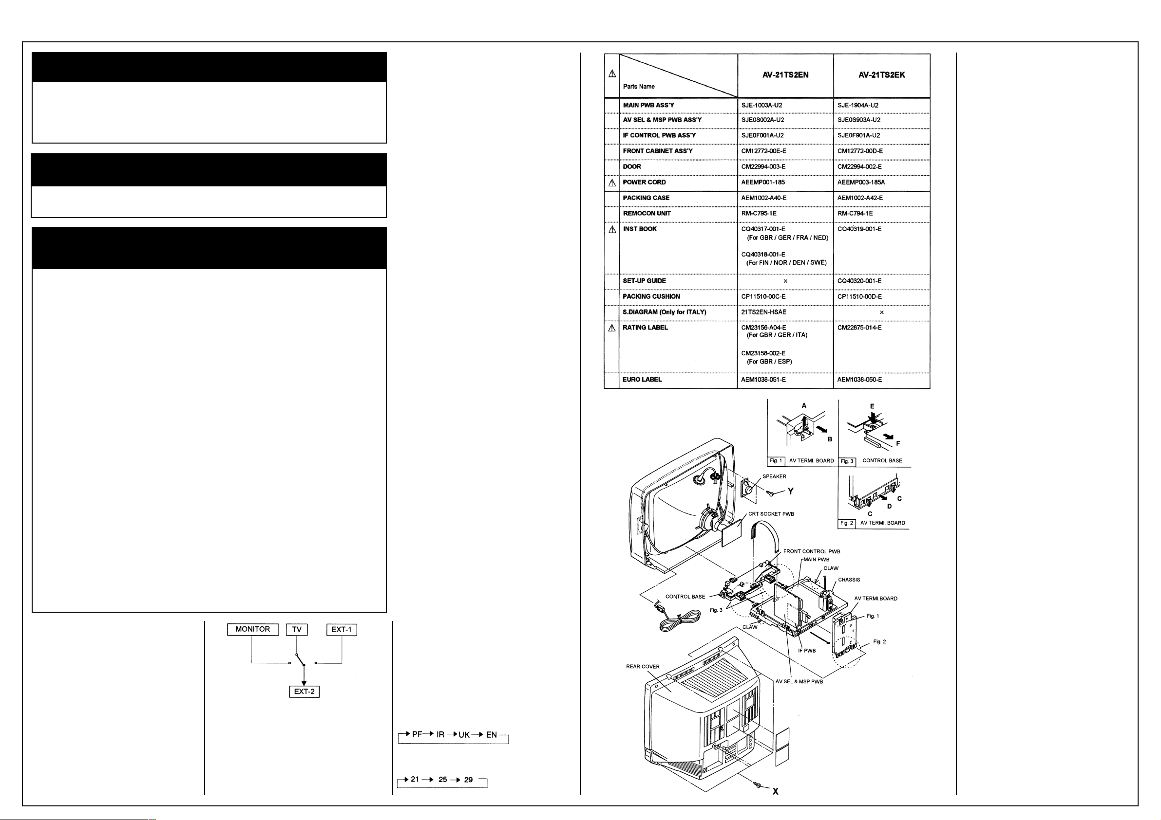
MAIN DIFFERENCE PARTS LIST
(See table opposite).
SPECIFIC SERVICE INSTRUCTIONS
DISASSEMBLY PROCEDURE
REMOVING THE REAR COVER
1. Unplug the power cord.
2. Remove the 6 screws marked X as shown in
the figure.
3. Withdraw the rear cover toward you.
REMOVING THE CHASSIS
• After removing the rear cover.
1. Slightly raise the both sides of the chassis by
hand and remove the two claws under the both
sides of the chassis from the front cabinet.
2. Withdraw the chassis backward. (If necessary,
take off the wire clamp, connectors etc.)
REMOVING THE AV TERMI. BOARD
• After removing the rear cover.
1. While raising the claw marked A, remove the
top of the AV TERMI. board slightly in the
direction of arrow B as shown in Fig. 1.
2. Pressing the claws marked C, remove the AV
TERMI. Board in the arrow direction marked D
as shown in Fig. 2 (Opposite).
REMOVING THE CONTROL BASE
1. While pushing down the claws marked E
remove the CONTROL BASE in the arrow
direction F as shown in Fig. 3. (If necessary,
take off the wire clamp, connectors etc.)
REMOVING THE SPEAKER
• After removing the rear cover.
1. Remove the two screws marked Y as shown in
figure.
2. Follow the same steps when removing the
other hand speaker.
CHECKING THE PW BOARD
1. To check the back side of the PW Board.
1) Pull out the chassis. (Refer to REMOVING THE
CHASSIS).
2) Erect the chassis vertically so that you can
easily check the back side of the PW Board.
[CAUTION]
• When erecting the chassis, be careful so that
there will be no contacting with other PW
Board.
• Before turning on power, make sure that the
wire connector is properly connected.
WIRE CLAMPING AND CABLE TIES
1. Be sure to clamp the wire.
2. Never remove the cable tie used for tying the
wires together. Should it be inadvertently
removed, be sure to tie the wires with a new
cable tie.
SETTING VALUES OF SYSTEM CONSTANT SET
Setting item
1. COUNTRY
Setting content
Setting item
2. INCH
Setting value [AV-21TS2EN]
EN
21"
Setting value [AV-21TS2EK]
UK
21"
USER SETTING VALUES - See Matrix
SERVICE MENU SETING ITEMS
Setting item:
1. IF
Setting value:
1. VCO
2. DELAY POINT
Setting item:
2. V/C
Setting value:
1. CUT OFF
2. DRIVE
3. BRIGHT
4. CONT.
5. COLOUR(PAL./SECAM/NTSC)
6. TINT(NTSC)
7. BLACK OFFSET(SECAM)
8. SHARP
9. TEXT(RGB) CONT
10. DC TRAN RATE
11. BLACK STRETCH
12. B.S.OFF
(Do not adjust)
(Do not adjust)
(Do not adjust)
(Do not adjust)
(Do not adjust)
Setting item:
3. AUDIO
(Do not adjust)
Setting value:
1. CONC LIMIT
2. A2 ID THR
Setting item:
4. DEF.
Setting value:
2. V-SHIFT
3. V-SIZE
4. H-CENT
7. V-S. CR (Fixed)
10. ABL POINT (Do
11. ABL GAIN (Do
not adjust)
not adjust)
Setting item:
5. VSM PRESET (COOL/NORMAL/WARM)
Setting value:
1. BRIGHT
2. CONT.
3. COLOUR
4. SHARP
5. TINT
6. R DRIVE
7. B DRIVE
8. BASS
9. TREBLE
Setting item:
6. VPS
(Do not adjust)
Setting value:
VPS
Setting item:
7. AUTO PROGRAM
(Do not adjust)
Setting value:
ON/OFF
BEFORE STARTING SERVICE ADJUSTMENTS - See Matrix
BASIC OPERATION OF SERVICE MENU -
See Matrix
Page 2

JVC AV-21TS2EK
Test point:
TP-47B
TP-E
[CRT SOCKET PWB]
Adjustment part:
5.COLOUR
(PAL~NTSC)
Description:
[Method of adjustment using measuring instrument]
Adjustment part:
PAL COLOUR
Description:
(PAL COLOUR)
1. Receive a PAL full field colour bar signal(75%
white).
2. Select 2.V/C from the SERVICE MENU.
3. Select 7.COLOUR with the FUNCTION UP/
DOWN key.
4. Set the initial setting value for PAL COLOUR
with the FUNCTION - or + key.
5. Connect the oscilloscope between TP-47B and
TP-E
6. Adjust PAL COLOUR and bring the value of (A)
in the illustration to +1V (voltage difference
between White and Blue).
7. Press the MENU key and memorize the setting
value.
Adjustment part:
NTSC 3.58 COLOUR
Description:
(NTSC 3.58 COLOUR)
1. Input a NTSC 3.58MHz COMPOSITE VIDEO
signal (full field colour bar with 75% white) from
the EXT terminal.
2. Set the initial setting value of NTSC 3.58
COLOUR with the FUNCTION -/+ key.
3. Adjust NTSC 3.58 COLOUR and bring the
value of (A) of the illustration to +5V (Voltage
difference between White and Blue).
4. Press the MENU key and memorize the setting
value.
(NTSC 4.43 COLOUR)
1. When NTSC 3.58 is set, NTSC 4.43 will be
automatically set at the respective values
For Adjustment of BLACK OFFSET (SECAM),
DEFLECTION CIRCUIT, V-SHIFT, V-SIZE,
H.CENTRE, V-S.CR and AUDIO CIRCUIT - See
Matrix
The End
For POWER SUPPLY CHECK, FOCUS, IF
CIRCUIT, VSM PRESET ADJUSTMENTS -
See Matrix
VIDEO/CHROMA CIRCUIT ADJUSTMENT
The setting (adjustment) using the REMOTE
CONTROL UNIT is made on the basis of the
initial setting values. The setting values which
adjust the screen to the optimum condition can
be different from the initial setting values.
Adjustment part:
SECAM COLOUR (AV-21TS2EN)
Description:
(SECAM COLOUR)
1. Receive a SECAM full field colour bar signal
(75% white).
2. Set the initial setting value of SECAM COLOUR with the FUNCTION -/+ key.
3. Adjust SECAM COLOUR and bring the value of
(A) of the illustration to 0 V (Voltage difference
between White and Blue).
4. Press the MENU key and memorize the setting
value.
This area is intentionally left blank.
Items in ( ) are automatically set to table.
(See table opposite).
For adjustment of WHITE BALANCE, SUB
BRIGHT, SUB CONT., SUB COLOUR I, SUB
TINT - See Matrix
Adjustment of SUB COLOUR II
Measuring instrument:
Signal Generator
Oscilloscope
Remote Control Unit
Page 3
Page 4

Page 5

Page 6

Page 7

Page 8

Page 9

Page 10

 Loading...