

Page 1
AV-2134EE/AV-21DTG2
SER VICE MANUAL
COLOUR TELEVISION
AV-21D10 / AV-21D10
AV-21DM10 / AV-21DM10
/AU
/-A
AV-21D10/AV-21DM10
BASIC CHASSIS
CG
AV-2134EE / AV-21DTG2
CONTENTS
/-A
SPECIFICATIONS
!
SAFETY PRECAUTIONS
!
FEATURES
!
FUNCTIONS
!
MAIN DIFFERENCE LIST
!
SPECIFIC SERVICE INSTRUCTIONS
!
SERVICE ADJUSTMENTS
!
PARTS LIST
!
★
OPERATING INSTRUCTIONS
★
STANDARD CIRCUIT DIAGRAM
1
・・・・・・・・・・・・・・・・・・・・・・・・・・・・・・・・
・・・・・・・・・・・・・・・・・・・・・・・・・・・・・・・・ ・・・・・・・・・・・・・・・・・・・・・・・・・・・・・・・・
・・・・・・・・・・・・・・・・・・・・・・・・・・・・・・・・・・・・・・・・・・・・・・・・・・・・・・・・・・・・・・・・
・・・・・・・・・・・・・・・・・・・・・・・・・・・・・・・・
・・・・・・・・・・・・・・・・・・・・・・・・・・・・・・・・ ・・・・・・・・・・・・・・・・・・・・・・・・・・・・・
・・・・・・・・・・・・・・・・・・・・・・・・・・・・・・・・・・・・・・・・・・・・・・・・・・・・・・・・・・・・・・・・
・・・・・・・・・・・・・・・・・・・・・・・・・・・・・・・・
・・・・・・・・・・・・・・・・・・・・・・・・・・・・・・・・ ・・・・・・・・・・・・・・・・・・・・・・・
・・・・・・・・・・・・・・・・・・・・・・・・・・・・・・・・・・・・・・・・・・・・・・・・・・・・・・・・・・・・・・・・
・・・・・・・・・・・・・・・・・・・・・・・・・・・・・・・・
・・・・・・・・・・・・・・・・・・・・・・・・・・・・・・・・ ・・・・・・・・・・・・・・・・・・・・・・・・・・・・・・・・
・・・・・・・・・・・・・・・・・・・・・・・・・・・・・・・・・・・・・・・・・・・・・・・・・・・・・・・・・・・・・・・・
・・・・・・・・・・・・・・・・・・・・・・・・・・・・・・・・
・・・・・・・・・・・・・・・・・・・・・・・・・・・・・・・・ ・・・・・・・・・・・・・・・・・・・・・・・
・・・・・・・・・・・・・・・・・・・・・・・・・・・・・・・・・・・・・・・・・・・・・・・・・・・・・・・・・・・・・・・・
・・・・・・・・・・・・・・・・・・・・・・・・・・・・・・・・
・・・・・・・・・・・・・・・・・・・・・・・・・・・・・・・・ ・・・・・・・・・・・・・・・・・・・・・
・・・・・・・・・・・・・・・・・・・・・・・・・・・・・・・・・・・・・・・・・・・・・・・・・・・・・・・・・・・・・・・・
・・・・・・・・・・・・・・・・・・・・・・・・・・・・・・・・
・・・・・・・・・・・・・・・・・・・・・・・・・・・・・・・・ ・・・・・・・・・・・・・・・・・・・・・・・・・・・・・・・・
・・・・・・・・・・・・・・・・・・・・・・・・・・・・・・・・・・・・・・・・・・・・・・・・・・・・・・・・・・・・・・・・
COPYRIGHT © 2001 VICTOR COMPANY OF JAPAN, LTD.
・・・・・・・・・・・・・・・・・・・・・・・・・・・・・
・・・・・・・・・・・・・・・・・・・・・・・・・・・・・・・・・・・・・・・・・・・・・・・・・・・・・・・・・・
・・・・・・・・・・・・・・・・・・・・・・・
・・・・・・・・・・・・・・・・・・・・・・・・・・・・・・・・・・・・・・・・・・・・・・
・・・・・・・・・・・・・・・・・・・・・・・・・・・・・・・・ ・・・
・・・・・・・・・・・・・・・・・・・・・・・・・・・・・・・・・・・・・・・・・・・・・・・・・・・・・・・・・・・・・・・・
・・・・・・・・・・・・・・・・・・・・・・・・・・・・・・・・ ・・
・・・・・・・・・・・・・・・・・・・・・・・・・・・・・・・・・・・・・・・・・・・・・・・・・・・・・・・・・・・・・・・・
・・・・・・・・・・・・・・・・・・・・・・・
・・・・・・・・・・・・・・・・・・・・・・・・・・・・・・・・・・・・・・・・・・・・・・
・・・・・・・・・・・・・・・・・・・・・・・・・・・・・・・・
・・・・・・・・・・・・・・・・・・・・・・・・・・・・・・・・ ・・・・・・・・・・・・・
・・・・・・・・・・・・・・・・・・・・・・・・・・・・・・・・・・・・・・・・・・・・・・・・・・・・・・・・・・・・・・・・
・・・・・・・・・・・・・・・・・・・・・
・・・・・・・・・・・・・・・・・・・・・・・・・・・・・・・・・・・・・・・・・・
・・・・・・・・・・・・・・・・・・・・・・・・・・・・・・・・ ・・・・
・・・・・・・・・・・・・・・・・・・・・・・・・・・・・・・・・・・・・・・・・・・・・・・・・・・・・・・・・・・・・・・・
・・・・・・・・・・・・・・・・・・・・・・・・・・・・・・・・
・・・・・・・・・・・・・・・・・・・・・・・・・・・・・・・・ ・・・・・・・・・・・・・・・・
・・・・・・・・・・・・・・・・・・・・・・・・・・・・・・・・・・・・・・・・・・・・・・・・・・・・・・・・・・・・・・・・
・・・・・・・・・・・・・
・・・・・・・・・・・・・・・・・・・・・・・・・・
・・・・・・・・・・・・・・・・
・・・・・・・・・・・・・・・・・・・・・・・・・・・・・・・・
・・・
・・・・・・
2
3
4
・・
5
・・・・
6
7
14
31
2-1
No. 51858
Oct. 2001
Page 2
A
A
REPLACEMENT OF MEMORY ICs
1. MEMORY ICs
This mod el uses memory ICs. This m em or y IC d at a ar e f or pr op er oper ation of the video and d efl ec tion circuit s .
When replaci n g m emor y ICs , be sure to use ICs written with the ini ti al v alu es of d ata.
V-21D10/AV-21DM10
V-2134EE/AV-21DTG2
2. PROCEDURE FOR REPLACING MEMORY ICs
(1) Power off
Switch th e p ow er off and disc onn ec t t h e pow er pl ug f r om the w al l outlet.
(2) Replace ICs
Be sure to u se memory ICs written with the initial data values.
(3) Power on
Connect the power plu g into the wall ou tl et an d s wit c h th e pow er on.
(4) Check and set SYSTEM CONSTANT SET
It must not adjust without adjustment signals.
・・・・
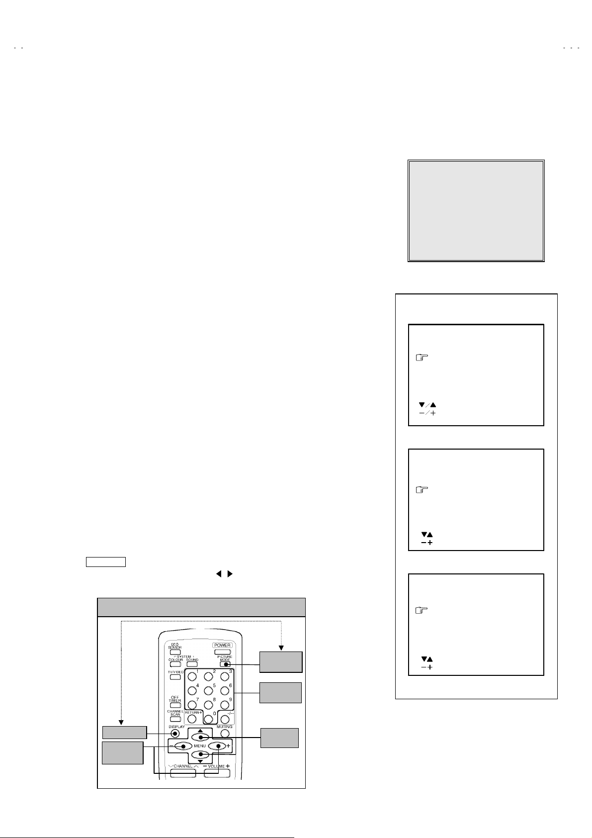
1) Press the
DISPLAY
CONTROL UNIT simultaneously.
2) T he SERVICE MEN U scr een of F ig . 1 wil l b e dis pl ay ed.
3) W hile the S ERVIC E MENU is dis pl ayed, ag ain press the
PICTURE MODE
screen of Fi g. 2 will be displayed.
1) Check the setti ng values of th e SYST EM C O NSTA NT SET of Table 1 I f t h e
value is dif ferent, s elect the s etting it em with the
the correct value with the
5) Press the
DISPLAY
(5) R ec eiv e channel of setting
Refer to the
(channels preset) as described
(6) User Setting
Check th e user set ting val ue of T able 2, and if setti ng valu e is diff erent, s et
the correct value.
For setting, refer to the
(7) Setting of SERVICE MENU
Verif y the s etti ng it ems of the S ER VICE ME NU of T abl e 3, and r es et wh ere
necessary.
For setting, refer to the
NOTE
Both
MENU -/+ Key and MENU
key and the
PICTURE MODE
key of the REMOTE
DISPLAY
key s imultaneous ly, and th e SYSTEM CONSTAN T SET
▼/▲key, and set
MENU
- / + key.
MENU
key twice, and return to the normal screen.
OPERATING INSTRUCTIONS
OPERATING INSTRUCTIONS
SERVICE ADJUSTMENTS
and set the receive channels
.
.
/ key have the same functions.
key an d
SERVICE MENU
1.IF 2.V/C
3.DEF 4.VSM PRESET
5.PRESET
6.TURBO TIMER OFF
1-6 SELECT DISP : EXIT
******
***********
***** **
************
**********
*** ** **
*** ** **** ***
*** ** ***** ** **
**.***
****
** ***
** ***** ***
***
******
Fig.1
SYSTEM CONSTANT-
SYSTEM CONSTANT SET 1
COLOUR
COLOUR :
COLOURCOLOUR
BILINGUAL
BILINGUAL : ***
BILINGUALBILINGUAL
TUNER
TUNER :
TUNERTUNER
ECO SENSOR
ECO SENSOR : YES
ECO SENSORECO SENSOR
LANGUAGE
LANGUAGE : E/R/A/F
LANGUAGELANGUAGE
: SELECT
: OPERATE DISP : EXIT
SYSTEM CONSTANT-
SYSTEM CONSTANT SET 2
B/B SOUND : NO
LOCK : 180
COLOUR AUTO : YES
QSS : MINT
ALC : NO
TEXT RATE : 20
:SEL
:OPE
SYSTEM CONSTANT-
ⅠⅠⅠⅠ
: *****
*****
: :
**********
: ***
: ***: ***
: **
**
: :
****
: YES
: YES: YES
: E/R/A/F
: E/R/A/F: E/R/A/F
ⅡⅡⅡⅡ
DISP:EXIT
ⅢⅢⅢⅢ
SYSTEM CONSTANT SET 3
AMP TUNER
KEY ASSIGNMENT OF REMOTE CONTROL UNIT
PICTURE
MODE key
NUMBERS
AMP TUNER : YES
AMP TUNERAMP TUNER
VNR
VNR : NO
VNRVNR
TEXT TABLE
TEXT TABLE :::: ***
TEXT TABLETEXT TABLE
:SEL
:OPE
: YES
: YES: YES
: NO
: NO: NO
***
******
DISP:EXIT
key
Fig.2
DISPLAY ke y
MENU
key
-/+
MENU
▼/▲
key
No. 51858
9
Page 3
A
V-21D10/AV-21DM10
A
A
V-2134EE/AV-21DTG2
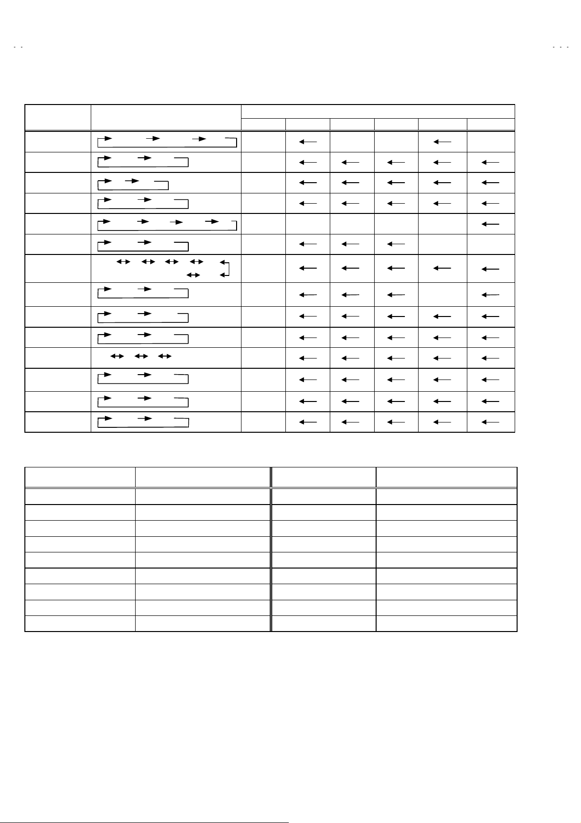
SETTING OF SYSTEM CONSTANT SET
Setting item Setting contents
COLOUR TRIPLE MULTI TRIPLE MULTI
MULTI.
PALTRIPLE
AV-21D10 AV-21D10
AV-21DM10 AV-2134EE AV-21DTG2
/AU
Mode
AV-21DM10
/-A
/-A
BILINGUAL NO
TUNER MU
ECO SENSOR YES
LANGUAGE E/R/C E/A/F/R E/A/R/F E/R/U E/A/R/F
B/B SOUND OFF NO NO
LOCK
COLOUR
AUTO
QSS MINT
ALC NO
TEXT RATE
AMP TUNER NO
VNR YES
TEXT TABLE CYL
YES NO
MA
MU
YES NO
E/A/R/F E/R/C
E/R/U
ON OFF
YES 10 20
230
~
250 240
YES
NO
MINT MQSS
YES NO
10 20 40 80
YES
YES
RA
NO
NO
CYL
E/F
180
NO YES
20
Table 1
USER SETTING VALUES
Setting item Setting value Setting item Setting value
MAIN POWER SW OFF PICTURE MODE (VSM) BRIGHT
SUB POWER ON LANGUAGE ENGLISH (ENG)
CHANNEL POSITION 1 POSITION CHANNEL PRESET Refer to OPERATING INSTRUCTION
VOLUME
TV/VIDEO
About 10 ECO SENSOR OFF
TV VNR OFF
ON SCREEN DISPLAY POSITION INDICATION AUTO SHUTOFF OFF
COLOUR SYSTEM AUTO PAL ON TIMER PR1 0:00
SOUND SYSTEM B / G BLUE BACK OFF
OFF TIMER OFF ( shown : 00 ) CHILD LOCK OFF
Table 2
10
No. 51858
Page 4
A
V-21D10/AV-21DM10
A
V-2134EE/AV-21DTG2
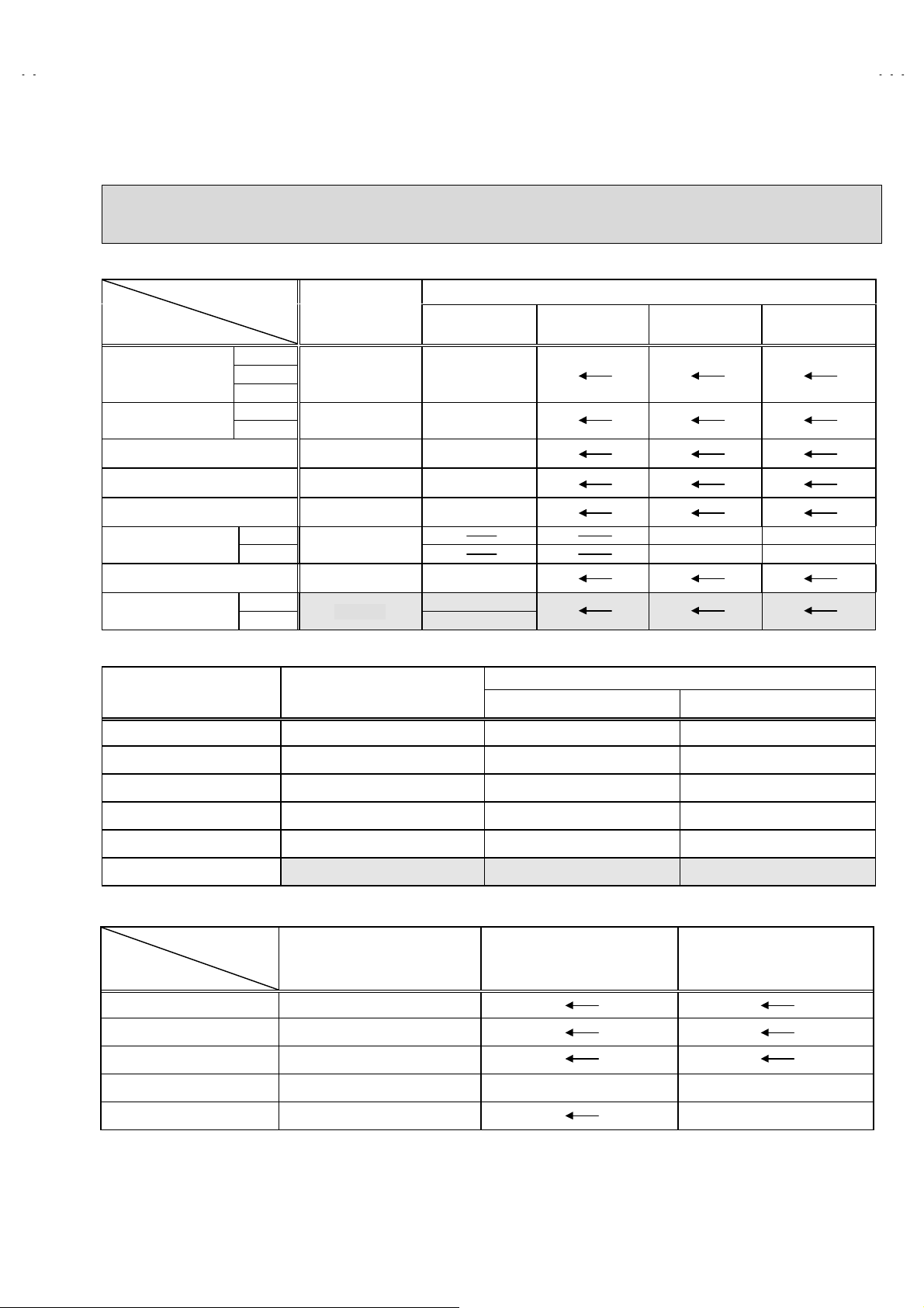
INITIAL SETTING VALUE OF SERVICE MENU
1. Adjustment of the SERVICE MENU is made on the basis of the initial setting values ; however, the new setting values which
set the screen in its optimum condition may differ from the initial setting.
2. Do not change the initial Setting Values of the Setting (Adjustment) items not listed In “ADJUSTMENT”.
2. V/C
Setting item
1. CUT OFF
2. DRIVE
3. BRIGHT
4. CONT.
5. COLOUR
6. TINT
7. SECAM BL ADJ.
8. SHARP
3. DEFLECTION
1. VER. POSITION
2. HOR. POSITION
(Do Not Adj.)
Setting item Variable range
Colour system
RED
GREEN
BLUE
RED
BLUE
TV
VIDEO
TV
VIDEO
Variable
range
-128~+127 -50
-128~+127 + 0
-127~+127 + 0
-63~+63 + 0
-63~+63 + 0
-63~+63
-31~+31 + 0
-32~+31
-04 ~ +03
-16 ~ +15
PAL SECAM NTSC 3.58 NTSC 4.43
- 8(Fixed)
+15(Fixed)
Initial settin g val ue
+ 0 + 0
+ 8 + 0
Initial settin g val ue
fv : 50Hz MODE fv : 60Hz MODE
- 1 - 3
+ 3 + 3
3. VER. HEIGHT
4. VER. LINEARITY
5. VER. SCURVE
6. HOR. VCO ADJUST
4. VSM PRESET
VSM preset
VSM mode
Setting item
SETTING VALUE +15
TINT
COLOUR
BRIGHT
CONT.
SHARP
SETTING VALUE +15
SETTING VALUE +15
SETTING VALUE +30 +15 +11
SETTING VALUE +15 +12
-64 ~ +63
-32 ~ +31
-32 ~ +31
-63 ~ +62
BRIGHT STANDARD SOFT
+35 + 1
+15 - 1
+32 + 0
+ 0 + 0
No. 51858
11
Page 5

A
V-21D10/AV-21DM10
A
V-2134EE/AV-21DTG2
5. PRESET
The items in the following table, it is no requirement for adjustment.
If values had changed by the miss operation, set the initial setting values in the following table.
Colour System (Do Not Ad ju st )
Setting item
1. C TRAP FIX
2. SHARP PEAK
PAL SEC AM NTSC 3.58 NTSC 4.43
111 1
000 0
Initial setting value (Fixed value)
3. ABL
4. GAMMA
5. Y. DELAY TIME
6. BLACK EXP START
7. C-BPF
8. CW / SCP
9. VIF DET LEVEL
11. IF AGC MIN
12. VIF AGC
13. VIF PMOD
19. VNR
20. RGB LIM
21. RGB LIM IT LEVEL
23. TEXT H. POSIT ION
TV
VIDEO
TV
VIDEO
111 1
000 0
022 3
020 2
3
+
110 0
111 1
000 0
000 0
000 0
000 0
000 0
15 15 15 15
111 1
222 2
-3 -3 -3 -3
3
+
3
+
3
+
24. READ DATA
Sound System (Do Not Adjust)
Setting item B/G I D/K M
10. SIF DET LEVEL
14. SIF BPF BW ADJUST
15. SIF TRAP FO ADJUST
16. SIF TRAP FO ADJUST 2
17. SIF - TRAP
18. SIF -BPF
22. SIF S W
12
0
+
0 (-) 0 (-) 0 (-) 0 (-)
0 (-) 0 (-) 0 (-) 0 (-)
0 (-) 0 (-) 0 (-) 0 (-)
000 0
000 1
111 0
0
+
0
+
0
+
No. 51858
Page 6

A
V-21D10/AV-21DM10
A
V-2134EE/AV-21DTG2
REPLACEMENT OF IC301 (IF V/C DECODER)
For the IC3 01(IF V/C DEC ODER) of this model , all data ar e written in t he micro-c omputer . So, write t he data in the micro-
"
comput er i n ac cor d ance with th e fol lo wi n g pr oc edures bef ore start in g adjustment.
PROCEDURES
Turn the POWER OFF.
(1)
Replace the IC301 with a new one.
(2)
While pr essi ng MENU but t on and VO L+ bu tt on O N t he FR ONT CAB INET s imu lt aneous l y, tur n the PO W ER ON. W hen th e P OW ER is
(3)
turned ON, the data is written in the micro-computer immediately.
LOCATIONS OF FRONT PANEL BUTTONS AND LAMPS
MENU buttons
①
CHANNEL ∨/∧ buttons
②
(MENU ∨/∧ buttons)
VOLUME -/+ buttons
③
(MENU -/+ buttons)
ECO sens or
④
REMOTE CONTROL sensor
⑤
ON TIMER lamp
⑥
POWER lamp
⑦
MAIN POWER button
⑧
1 2 3 4 5 6 7 8
No. 51858
13
Page 7

A
V-21D10/AV-21DM10
A
V-2134EE/AV-21DTG2
SERVICE ADJUSTMENTS
BEFORE STARTING SERVICE ADJUSTMENT
1. There are 2 way of adjusting this TV: One is with the
REMOTE CONTRO L UNIT and t he oth er is t he conv ention al
method using adjustment parts and com ponents.
2. The ad justm ent w ith the REM OTE C ONTROL UNIT is mad e
on the basis of the initial setting values. The setting values
which adjust th e screen t o it s o p timum c on d ition may d iff er
from the initial setting values.
3. Make sure that connection is correctly made to AC power
source.
4. Turn on the p ower of the set and equipmen t before us e, and
start the adjustment procedures after waiting at least 30 minutes.
5. Unless other wise spec ified, prepare t he most suitab le rec eption
or input signal for adjustment.
6. Never touch any adjustment setting value, which are not
specified in the list for this adjustment.
7. Preparation for adjustment
Unless oth erwis e sp ec ified i n th e adjustment ins truc tions, p r eset
the following functions with the REMOTE CONTROL UNIT.
User mode positi on
PICTURE MODE (VSM) BRI GHT
VNR OFF
COLOUR / BRIGHT
CONT. / SHARP
BLUE BACK OFF
OFF TIMER OFF
ECO SENSOR OFF
AUTO SHUT OFF OFF
Refer to VSM PRESET
MEASURING INSTRUMENT AND FIXTURES
1. DC voltmeter (or digital voltmeter)
2. Oscilloscope
3. Signal generator (Patte rn generator) [PAL / SECAM / NTSC]
4. Remote control unit
ADJUSTMENT ITEMS
Adjustment item Adjustment item
B1 POWER SUPPLY
FOCUS adjustm ent VSM PRESET setting
IF circuit adjustment
V/C (Video / Chroma) circuit
adjustment
DEF. circuit adjustment
PURITY / CONVERGENCE adjustment
14
No. 51858
Page 8

A
V-21D10/AV-21DM10
A
V-2134EE/AV-21DTG2
BASIC OPERATION OF SERVICE MENU
The adjustment using SERVICE MENU
"
The followi ng adjustm ent items us e the SERVICE ME NU in the seri es of the adjust ment. The adjus tments are made on the basis of the
initial setting values. The adjustment values which adjust the screen to the optimum condition can be different from the initial setting values.
With the SERVICE MENU, various settings can be made, and they are broadly classified in the following items of settings.
1.IF
・・・・・・・・・・・・・・・・・・・・・・・・
2.V/C
・・・・・・・・・・・・・・・・・・・・・・
3.DEF
・・・・・・・・・・・・・・・・・・・・・
4.VSM PRESET
5.PRESET
6.TURBO TIMER
Key operation of the SERVICE MENU
"
・・・・・・・・・・・・・
・・・・・・・・・・・・・・・・・
・・・・・・・・・・・・
[Enter to SERVICE MENU]
Press the
DISPLAY
key and th e
UNIT simultaneously. Then enter the SERVICE MENU mode as shown in Fig.1.
Adjustment of the IF circuits.
Adjustment of the VIDEO/CHROMA circuit.
Adjustment of the DEFLECTION circuit.
Adjustm en t of th e initial s ettin g values of VSM condit i on as STANDAR D , SO FT and BRIGH T.
(VSM : Video Status Memory)
Adjustmen t of the RF circuit
[Do not adjust]
.
For quick s et ti ng t h e TI MER c ou nt value, ad jus t able not onl y b y minuets but also by sec on d.
[Should be OFF]
PICTURE M ODE
.
key of the REMOTE CONTROL
[Exit from SERVICE MENU]
When complete the adjustment work, press the
DISPLAY
key to return to the
SERVICE MENU.
And then press the
DISPLAY
key again, return to the normal screen.
[Select from SERVICE MENU]
In SERVICE MENU , press t h e num b er (1~6) key of the remote control unit, to select
any of the adj ustmen t it ems .
SERVICE MENU
KEY ASSIGNMENT OF REMOTE CONTROL UNIT
SERVICE MENU
1.IF 2.V/C
3.DEF 4.VSM PRESET
5.PRESET
6.TURBO TIMER OFF
1-6 SELECT DISP : EXIT
******
***********
***** **
************
**********
*** ** **
*** ** **** ***
*** ** ***** ** **
**.***
****
** ***
** ***** ***
***
******
Fig.1
DISPLAY ke y
MENU
key
-/+
PICTURE
MODE key
NUMBERS
key
MENU
key
▼/▲
(RM-C364GY)
No. 51858
15
Page 9

A
V-21D10/AV-21DM10
A
V-2134EE/AV-21DTG2
[Method of setting]
1. IF
[1. VCO]
1 Key
①
②
③
④
[2. DELAY POINT]
①
②
③
④
・・・・・・・・・・・・・・・・・・・・・・・・・
1 Key
・・・・・・・・・・・・・・・・・・・・・・・・・
The VCO (CW) screen will be displayed a allow mark wh en the AF C vol t age is at a certai n level.
DISPLAY Key
1 Key
・・・・・・・・・・・・・・・・・・・・・・・・・
2 Key
・・・・・・・・・・・・・・・・・・・・・・・・・
MENU -/+
DISPLAY Key
・・・・・・・・・・・・・・・・・・・・・
・・・・・・・・・・・・・・・・・
・・・・・・・・・・・・・・・・・
Select
Select
When this is pressed twice, you will return to the
Select
Select
Set (adjust) the setting values of the setting items.
When this is pressed twice, you will return to the
.
1.IF
1.VCO
.
1.IF
2.DELAY POINT
.
SERVICE MENU
SERVICE MENU
.
.
2.V/C, 3.DEF
2~4Key
①
MENU ▼/▲ Key
②
MENU -/+
③
DISPLAY Key
④
6.TURBO TIMER
By pressing the 6 key, you can change the ON or OFF (
①
and
4.VSM PRESET
・・・・・・・・・・・・・・・・・・・・・・・
・・・・・・・・・・・・・・
・・・・・・・・・・・・・・・・・・・・・
・・・・・・・・・・・・・・・・・・
(Should be OFF)
If it is ON, the timer in TIMER mode changes from 1 minute into 1 sec temporarily.
%
(It is easier to checks the Operation of TIMER)
If you turn the TV power off, this setting becomes OFF automatically.
Select on e from
Select setting items.
Adjust the setting values of the setting items.
When this is pressed, return to the
2. V/C, 3. DEF
should be OFF
and
4. VSM PRESET
SERVICE MENU
).
.
.
16
No. 51858
Page 10

A
A
SERVICE MENU FLOW CHART
(R)
(G)
(B)
V-21D10/AV-21DM10
V-2134EE/AV-21DTG2
SERVICE MENU
SERVICE MENU
1.IF 2.V/C
3.DEF 4.VSM PRESET
5.PRESET
6.TURBO TIMER OFF
1-6 SELECT DISP : EX IT
******
****** *****
***** **
************
**********
*** ** **
*** ** ** ** ***
*** ** ***** ** **
6.TURBO TIMER
** ***
** ***** ***
OFF
ON /
**.***
***
****
******
OFF
(By pressi ng 6-key)
SUB MENU 1. IF
IF
1. VCO
2. DELAY POINT
1-2 : SELECT DISP : EXIT
SUB MENU 2. V/C
V/C PAL
1. CUTOFF
50Hz
/ :SELECT
- / + : OPERATE DISP : EXIT
* **
* **
* **
VCO (CW)
TOO HIGH
ABOVE REFERENCE
JUST REFERENCE
BELOW REFERENCE
TOO LOW
AFT ADJUST
VCO ADJUST
FINE
DELAY POINT UHF
AGC TAKE-OVER
- / + : OPERATE DISP : EXIT
MHz
***.**
***(**)
***(**)
***(**)***(**)
***(**)
***(**)
***(**)***(**)
DISP : EXIT
**
SUB MENU 3. DEF
DEF
1. VER. POSITION
50Hz
/ :SELECT
- / + : OPERATE DISP : EXIT
PAL
***
SUB MENU 4. VSM PRESET
BRIGHT
TINT
COLOUR
BRIGHT
CONT.
SHARP
/ :SELECT
- / + : OPERATE DISP : EXIT
**
**
**
**
**
SUB MENU 5. PRESET
PRESET
1. C-TRAP FIX
50Hz
/ :SELECT
- / + : OPERATE DISP : EXIT
PAL
No. 51858
B/G
***
17
Page 11

BLOCK DIAGRAM
TU001
TUNER
AV-21D10/AV-21DM10
AV-2134EE/AV-21DTG2
IF
Q102
IF AMP
SF101
AV-21D10/AV-21DM10
AV-2134EE/AV-21DTG2
AUDIO
IC651
AUDIO AMP
3
SP
OUT
8
SP
SF102
REAR
VIDEO
IN
AUDIO
VIDEO
OUT
AUDIO
IC702
MEMORY
SCL
SDA
37.38
SCL
SDA
3.58/
OTH
IC701
MICRO COMPUTER
HEAD
Q103
SW
SCL/SDA
25
18.19
SAW
30
AUDIO
OUT
IC201
ECO
REMOCON
KEY
1 CHIP DECODER
IND.
R / G /B
IC421
OSD
RGB
30.31.32
6.7.8
EXT
RGB
VIDEO
IN
24
VIDEO
OUT
38
AUDIO
IN
RGB
10.11.12
29
H.OUT V.OUT
42
46
V.OUT
PHONE
FRONT
IN
VIDEO
AUDIO
CRT SOCKET PWB
RGB
DRV
V01
CRT
VERT.OUT
REG.
DY(V)
SP
AC IN
POWER SW
D901
RECT
CF901
No.51858
IC921
POWER
REG.
PC921
VOLTAGE
FEEDBACK
T921
SW
TRANSF.
IC971
9V REG.
IC941
ERROR
AMP
IC972
5V REG.
B1
2-3 2-4
REG.
H.OUT
MAIN PWB
Q522
H.OUT
No.51858
B1
T522
HVT
DY(H)
DEF.YOKE
FOCUS
SCREEN
EHV
Page 12

AV-21D10/AV-21DM10
AV-2134EE/AV-21DTG2
AV-21D10/AV-21DM10
AV-2134EE/AV-21DTG2
CIRCUIT DIAGRAMS MAIN PWB CIRCUIT DIAGRAMS
4.9V
4.9V
0.7V
4.7V
0V
0V
4.9V
1.7V
4.9V
4.2V
0.1V
2.4V
0V0V
4.9V
4.1V
4.9V
0V
0V
2.9V
4.9V
0V
0V
4.9V
4.9V
4.9V
4.7V
[1/2]
4.9V 0V
4.4V4.4V4.7V
MAIN PWB
4.9V
4.1V
5.4V
5V
AT24C08-21DTT2
4.9V
4.9V
4.8V
4.9V
4.9V
4.9V
4.9V
4.7V
0.1V
0V
0V
14.4V
4.9V
3W
4.9V
4.9V
10.5V
0.3V
15.1V
-2.2V
5.5V
12.4V
15V
0V
0.6V
10.9V
10.7V
0.3V
22.1V
0V
SCG-1023A-H2
(AV-21DTG2-A)
SCG-1025A-H2
(AV-21DM10)
SCG-1026A-H2
(AV-21D10)
SCG-1027A-H2
(AV-2134EE)
SCG-1281A-H2
(AV-21D10-AU)
IC301 36
2
-H2
-H2
-H2
-H2
-H2
9V
4.9V
4.2V
4V
3.3V
0V
4.9V
4.9V
3.3V
8.1V
4.8V
4.1V
2.4V
4.9V
4.9V
1.2V1.2V
0V
2.4V
0V2.4V
1.3V1.3V
1.2V
2.4V0.7V
3.3V
3.2V
1.2V
1.2V
1.3V
1.2V
2.4V
0.2V
0.1V0.2V
0V
0.3V
0.8V
0.1V
0.5V
4.9V
2.2V
1.5V
3.7V
0V
0V
0V
3.3V
4.3V0.6V
0V
4V
4V
1.7V
0.1V
0.5V
3.8
4.9V
0V
0.5V
4.1V
0.1V
9V
0.2V
V
0.1
V
6.2V4.2V
5V
4.9V
3V
3.3V
0V
4.9V
4.9V
0.9V
3.7V1.1V
3.4V
9V
4.9V
3.2V
4.3V2.7V
6.2V
2.8V
3.1V3.1V
4.2V
4.2V8.5V
4.2V
4.6V
4.2V
4.1V
9V
3.6V
3.9V3.2V
3.4V
IC301
39
2
3.8V
9V
4.1V
2.7V
2.7V
1.8V
1.8V
3.4V
2.9V3.2V3.6V
9V
2.2V
1.5V
42
2.5
0V
32.6V
4.9V
4.3V
4.2V
1.8V
46
2.2
0.3V
0V
3.4
IC301
IC301
11
12
3.4
No.51858 No.51858
2-5 2-6
IC301
3
10
Page 13

MAIN PWB CIRCUIT DIAGRAM [2/2]
QMPR340-165-K2
[AV-21D10/AV-21DM10/AV-2134EE]
QMP2980-185-J5
[AV-21D10-AU]
QMPR010-200-E2 or QMPR010-200-K2
[AV-21DM10-A/AV-21DTG2-A]
.1 AC275V MPP
AV-21D10/AV-21DM10
AV-2134EE/AV-21DTG2
AV-21D10/AV-21DM10
AV-2134EE/AV-21DTG2
IC421 5
50
IC421 3 6
25
CRT COCKET
PICTURE TUBE
A51KQK99X
QQW0077-001
3.7V 24.7
1V
V
14.6
V
p AC250V
15.4V
14.6V
3.9V
9V
15.2V
4.9V
1
20
0V
Q521 B
Q521 C
5.5V
Q522 B
2
0.2V
9.7V
-0.2V
250V MPP
.047
AC250V
AC250V
137.5V
0.1V
16.9V
1V
p AC250V
AC250V
11.8V
11.4V 4.9V
0.1V
24.9V
3.7V
7.2V
0.2V
0.2V
1.5KVH MPP
QFZ0200-972
1/2W
QQH0102-001
CRT SOCKET PWB
(Within MAIN PWB)
SCG-1023A-H2
(AV-21DTG2-A)
SCG-1025A-H2
(AV-21DM10,AV-21DM10-A)
SCG-1026A-H2
(AV-21D10)
SCG-1027A-H2
(AV-2134EE)
SCG-1281A-H2
(AV-21D10-AU)
Q353 C
120
Q352 C
120
(1/2)
Q351 C
120
3.9 10W
114.8V
TR-91
(B1)
0V
114.5V
QQD0061-001
1000
1
No.51858
T522
3
70
7
28
4.9V
0V
16.9V
15.4V
6V
14.3V
5.5V
-H2
-H2
-H2
3.9 10W
4.7 7W
4.7 7W
-H2
-H2
4.7 7W
AC250V
1/2W
0V
0V
No.51858
114.9V
13.8V
4.3V
SCG-1023A-H2
SCG-1025A-H2
SCG-1026A-H2
SCG-1027A-H2
SCG-1281A-H2
MAIN PWB
(AV-21DTG2-A)
(AV-21DM10,AV-21DM10-A)
(AV-21D10)
(AV-2134EE)
(AV-21D10-AU)
2-7 2-8
(1/2)
TP-E
2.2 1/4W
5
240
9
220
 Loading...