

Page 1
AV-2108TEE AV-2908TEE
AV-2508TEE AV-3408TEE
SERVICE MANUAL
COLOUR TELEVISION
BASIC CHASSIS
CH
AV-2108TEE
AV-2508TEE
POWER
DISPLAY
MENU
CHANNEL VOLUME
SYSTEM
SOUND MUTING
COLOUR
TV/VIDEO
123
456
PICTURE MODE
7809
RETURN
CHANNEL SCAN
-/--
OFF TIMER
TV/TEXT
ECO SENSOR
TEXT
REVEAL HOLD INDEX STORE
MODE SIZE SUBPAGE CANCEL
RM-C355 REMOTE CONTROL UNIT
RM-C355-1C
/B
/B
AV-2908TEE
AV-3408TEE
/B
/B
Regarding service information other than these sections, refer to the AV-2108TEE service
manual (No. 51849), AV-2508TEE service manual (No. 51848), AV-2908TEE service manual
(No. 51839) and AV-3408TEE service manual (No.51854).
Also, be sure to note important safety precautions provided in the service manual.
COPYRIGHT © 2001 VICTOR COMPANY OF JAPAN, LTD.
No. 51901
Sep. 2001
Page 2

AV-2108TEE AV-2908TEE
AV-2508TEE AV-3408TEE
CONTENTS
a SPECIFIC SERVICE INSTRUCTIONS [AV-2108TEE/B] ......................................................................... 3
a SERVICE ADJUSTMENTS [AV-2108TEE/B] .......................................................................................... 4
a PARTS LIST [AV-2108TEE/B] ................................................................................................................ 9
a SPECIFIC SERVICE INSTRUCTIONS [AV-2508TEE/B] ....................................................................... 18
a SERVICE ADJUSTMENTS [AV-2508TEE/B] ........................................................................................ 19
a PARTS LIST [AV-2508TEE/B] ............................................................................................................... 24
a SPECIFIC SERVICE INSTRUCTIONS [AV-2908TEE/B] ....................................................................... 30
a SERVICE ADJUSTMENTS [AV-2908TEE/B] ........................................................................................ 31
a PATTERN DIAGRAMS [AV-2908TEE/B] ............................................................................................... 38
a PARTS LIST [AV-2908TEE/B] ............................................................................................................... 40
a SPECIFIC SERVICE INSTRUCTIONS [AV-3408TEE/B] ....................................................................... 49
a SERVICE ADJUSTMENTS [AV-3408TEE/B] ........................................................................................ 50
a PATTERN DIAGRAMS [AV-3408TEE/B] ............................................................................................... 53
a PARTS LIST [AV-3408TEE/B] ............................................................................................................... 54
2 No. 51901
Page 3
AV-2108TEE
SPECIFIC SERVICE INSTRUCTIONS [AV-2108TEE/B]
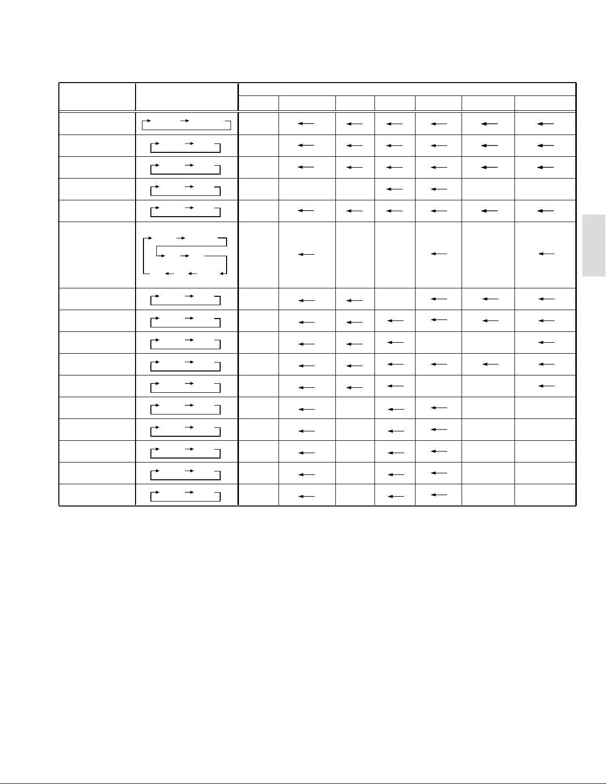
SETTING OF SYSTEM CONSTANT SET
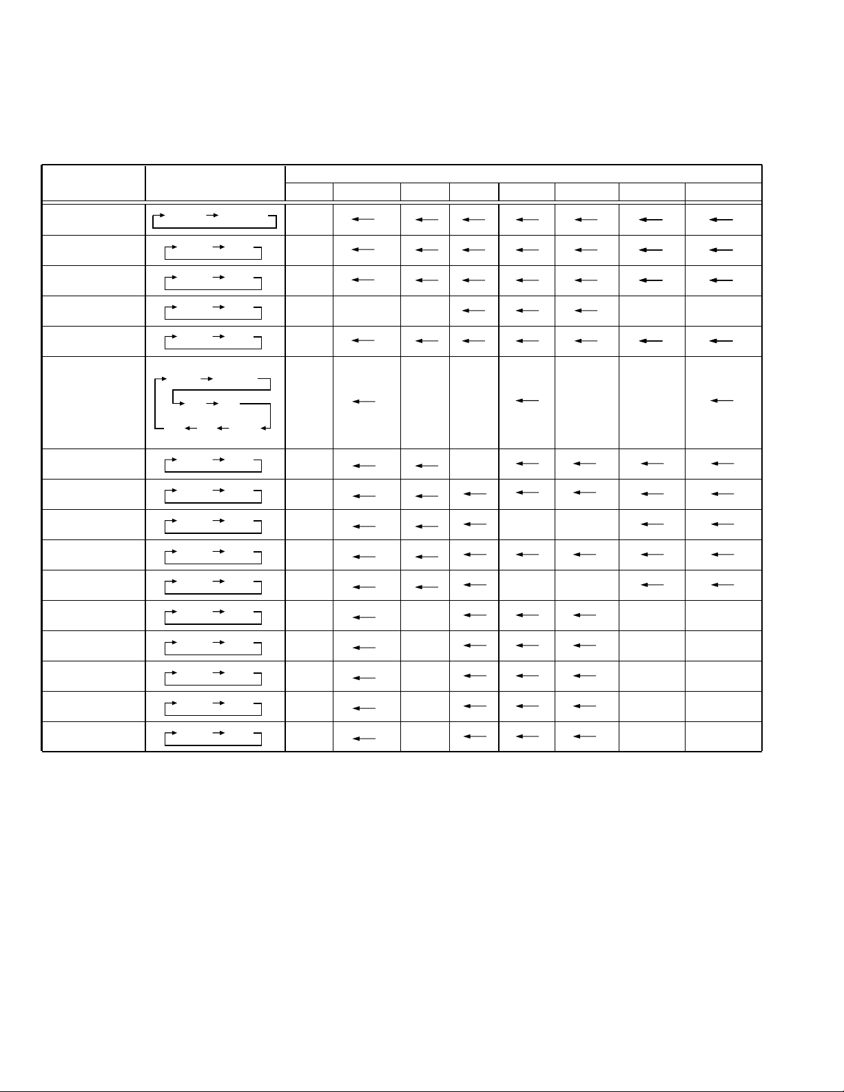
Setting item Setting content
AV-21LS AV-21LS-AU AV-21LXAV-21LH AV-2108TEE AV-2108TEE/BAV-21X-A
Setting value
SYSTEM
COMB
TILT
TEXT
SUPER BASS
LANGUAGE
MSP
BILINGUAL
B/B SOUND
TUNER
COLOUR AUTO
LOCK 1MHz
MULTI TRIPLE
YES NO
YES NO
YES NO
YES NO
E/R/C E/R/A/F
E/F E/A
E/R E/C E/A/F
YES NO
YES NO
YES NO
MU MA
YES NO
000 024
MULTI
NO
NO
ARABIC
NO
E/R/C
YES
NO
NO
MU
NO
020(040)
PAN EURO NO
E/C E/R/A/F E/R
020
NO
YES
YES
RUSSIAN UKRANIAN
NO
NO
020(040)
(040)
AV-2108TEE
500KHz
250KHz
156.25KHz
31.25KHz
NOTE : (
000 024
000 024
000 024
000 024
) is for Micon (IC1701) Part No. TDA9365N13S0518.
***
020(040)
020(040)
015(030)
015(030)
Table 1
020
020
015
015
020(040)
020(040)
015(030)
015(030)
(040)
(040)
(030)
(030)
No. 51901 3
Page 4
AV-2108TEE
SERVICE ADJUSTMENTS [AV-2108TEE/B]
VC (VIDEO/CHROMA) CIRCUIT ADJUSTMENT
The setting (adjustment) using the remote control unit is made on the basis of the initial setting values.
The setting values which adjust the screen to the optimum condition can be different from the initial setting values.
Do not change the initial setting values of the setting (adjustment) items not listed in “ADJUSTMENT”.
•
[SUB MENU 2. VC] : Do not adjust.
Setting (Adjustment) item Variable range
Initial setting value
PAL SECAM NTSC3.58 NTSC4.43 COMPONENT
1 CUTOFF(R/G) –7 — +8 0
2 DRIVE(R/G/B) –30 — +31 0
3 BRIGHT(COM./TV/V-1/V-2/V-3) –30 — +31 0/–18/0/0/0
4 CONT –30 — +31 –20 —
5 COLOUR –30 — +31 –5 –3 –12 –2 +10
6 TINT (TV/VIDEO) –30 — +31 — — –15/+4 +1/+1 —
7 SHARP (TV/VIDEO) –30 — +31 –16/–2 –/0
8 YDELAY (TV/VIDEO/S) –8 — +7 0/+1/0 +5/+1/+1 0/+1/+1 +5/0/+1 —
Item
Adjustment
of WHITE
Measuring
instrument
Signal
generator
Test point Adjustment part Description
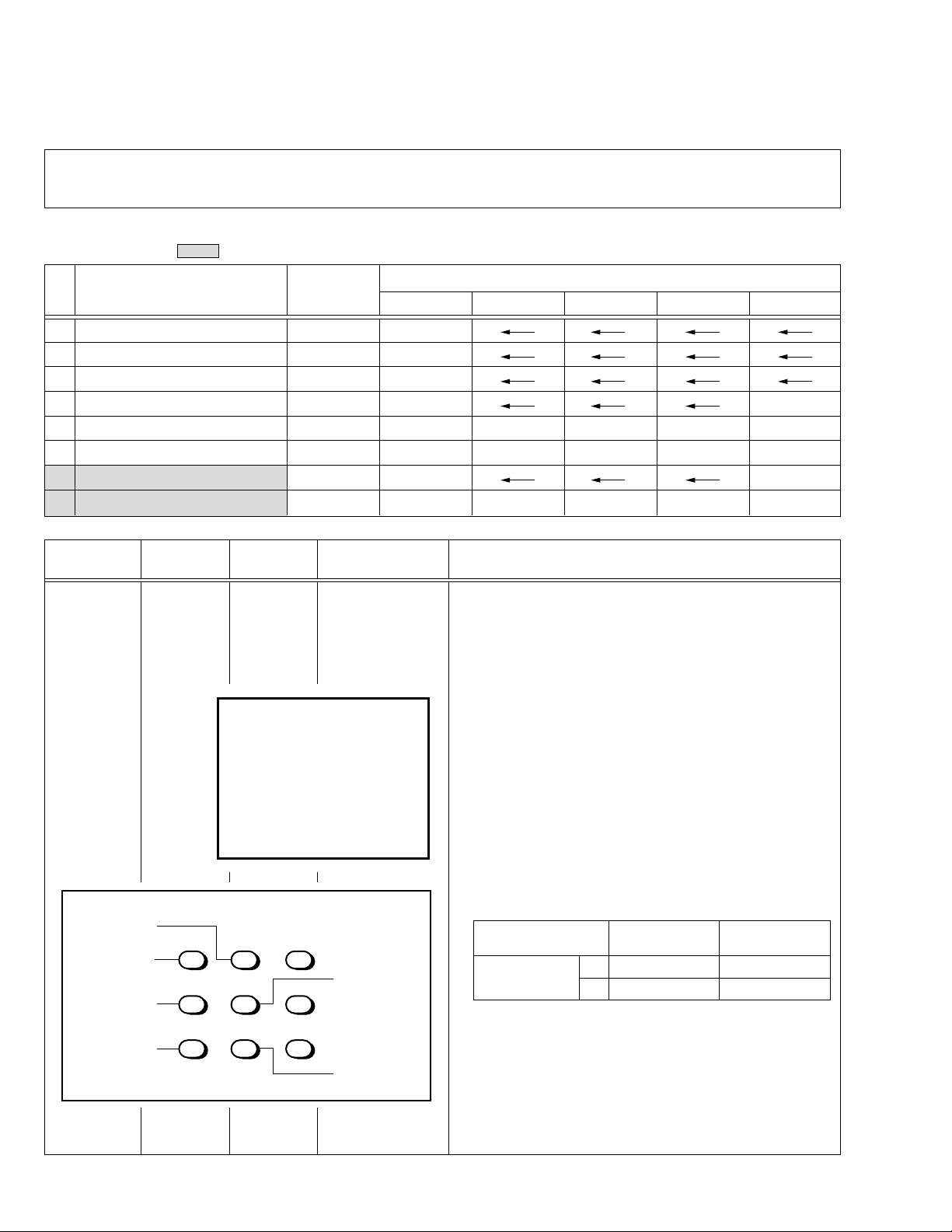
1. CUTOFF (R)
CUTOFF (G)
Note:
• Set PICTURE MODE (VSM) to “BRIGHT”.
BALANCE
(Low light)
Remote
control unit
SCREEN VR
[In HVT]
1. Receive a PAL black and white signal (colour off).
2. Select 2. VC from the SERVICE MENU.
3. Select 1. CUTOFF (R) and (G) with MENU &/^ key, and set each
value to initial setting value with the 4 and 7 keys, or 5 and 8 keys on
V/C
1. CUTOFF
50 Hz
MENU 89: SELECT
MENU
(R)
(G)
-
/+ : OPERATE
PAL
**
**
DISPLAY : EXIT
the remote control unit.
4. Press the 1 key on the remote control unit to produce a single hori-
zontal line.
5. Turn the SCREEN VR fully counterclockwise, then slowly turn it clockwise to where a red, blue or green colour is faintly visible.
6. Use the keys 4 and 7 or 5 and 8 on the remote control unit and
adjust the other 2 colours to where the single horizontal line appears white.
7. Turn the SCREEN VR to where the single horizontal line glows faintly.
8. Press the 2 key to return to 1. CUTOFF screen.
9. Press the DISPLAY key twice to return to the normal screen.
Setting (Adjustment) Variable Initial setting
Item range value
1. CUT OFF
R –7 — +8 0
G –7 — +8 0
H.LINE OFF
H.LINE ON
R. CUTOFF (
REMOTE CONTROL UNIT
12 3
4
8
)
56
G. CUTOFF (8)
789
R. CUTOFF (
)
9
G.CUTOFF (
)
9
4 No. 51901
Page 5
AV-2108TEE
Item
Adjustment
of
SUB
COLOUR-I
Measuring
instrument
Remote
control unit
Test point Adjustment part Description
5. COLOUR
[Method of adjustment without measuring instrument]
Notes:
• Proceed to the following this adjustment after having completed the
adjustment of SUB CONT.
• Set PICTURE MODE (VSM) to “BRIGHT”.
– PAL COLOUR –
1. Receive a PAL broadcast.
2. Select 2. VC from the SERVICE MENU.
3. Select 5. COLOUR with the MENU &/^ key.
4. Set the initial setting value for PAL COLOUR with the MENU –/+ key.
5. If the colour is not best with the initial setting value, make fine ad-
justment until you get the best colour.
6. Press the DISPLAY key twice to return to the normal screen.
– SECAM COLOUR –
7. Receive a SECAM broadcast.
8. Press the COLOUR SYSTEM button on the remote control unit to
select the SECAM colour system.
9. Make fine adjustment of SECAM COLOUR in the same way as for
“PAL COLOUR”.
– NTSC 3.58 COLOUR –
10. Receive a NTSC 3.58MHz broadcast.
11. Press the COLOUR SYSTEM button on the remote control unit to
select the NTSC 3.58 colour system.
12. Make similar fine adjustment of NTSC 3.58 COLOUR in the same
way as for “PAL COLOUR”.
– NTSC 4.43 COLOUR –
When adjustment is done for NTSC 3.58 COLOUR, appropriate
values are automatically set for NTSC 4.43 COLOUR.
AV-2108TEE
Adjustment
of SUB
COLOUR-II
Signal
generator
Oscilloscope
Remote
control unit
Cy
Y
W
TP-47G
TP-E (H)
[CRT
SOCKET
PWB]
Mg
G
5. COLOUR [Method of adjustment using measuring instrument]
Notes:
• Proceed to the following this adjustment after having completed the
adjustment of SUB CONT.
• Set PICTURE MODE (VSM) to “BRIGHT”.
– PAL COLOUR –
1. Receive a PAL colour bar signal (full field colour bar 75% white).
2. Select 2. VC from the SERVICE MENU.
3. Select 5. COLOUR with the MENU &/^ key.
4. Set the initial setting value of PAL COLOUR with the MENU –/+ key.
5. Connect the oscilloscope between TP-47G and TP-E.
B
R
(A)
(–)
0V
(+)
6.
Adjust PAL COLOUR to set the value (A) in the figure to +14V (V
W-G
– SECAM COLOUR –
7. Receive a SECAM colour bar signal (full field colour bar 75% white).
8. Press the COLOUR SYSTEM button on the remote control unit to
select the SECAM colour system.
9. Set the initial setting value of SECAM COLOUR with the MENU –/+ key.
).
10. Adjust SECAM COLOUR to set the value (A) in the figure to +5V
(VW-G ).
– NTSC 3.58 COLOUR –
11. Receive a NTSC 3.58 colour bar signal (full field colour bar 75% white).
12. Press the COLOUR SYSTEM button on the remote control unit to
select the NTSC 3.58 colour system.
13. Set the initial setting value of NTSC 3.58 COLOUR with the MENU
–/+ key.
14. Adjust NTSC 3.58 COLOUR to set the value (A) in the figure to
+5V (VW-G).
– NTSC 4.43 COLOUR –
When adjustment is done for NTSC 3.58 COLOUR, appropriate
values are automatically set for NTSC 4.43 COLOUR.
No. 51901 5
Page 6
AV-2108TEE
Item
Adjustment
of
SUB TINT-I
Measuring
instrument
Remote
control unit
Test point Adjustment part Description
6. TINT [Method of adjustment without measuring instrument]
Notes:
• Proceed to the following this adjustment after having completed the
adjustment of SUB CONT.
• Set PICTURE MODE (VSM) to “BRIGHT”.
– NTSC 3.58 TINT –
1. Receive a NTSC 3.58 colour bar signal (full field colour bar 75%
white).
2. Press the COLOUR SYSTEM button on the remote control unit to
select the NTSC 3.58 colour system.
3. Select 2. VC from the SERVICE MENU.
4. Select 6. TINT with the MENU &/^ key.
5. Set the initial setting value of NTSC 3.58 with the MENU –/+ key.
6. If you cannot get the best tint with the initial setting value, make fine
adjustment until you get the best tint.
7. Press the DISPLAY key twice to return to the normal screen.
– NTSC 4.43 TINT –
When adjustment is done for NTSC 3.58 TINT, appropriate values are
automatically set for NTSC 4.43 TINT.
Adjustment
of SUB
SUB TINT-II
Signal
generator
Oscilloscope
Remote
control unit
(B)
W
Y
Cy
TP-47G
TP-E (H)
[CRT
SOCKET
PWB]
B
Mg
R
G
6. TINT [Method of adjustment using measuring instrument]
Notes:
• Proceed to the following this adjustment after having completed the
adjustment of SUB CONT.
• Set PICTURE MODE (VSM) to “BRIGHT”.
– NTSC 3.58 TINT –
1. Receive a NTSC 3.58 colour bar signal (full field colour bar 75%
white).
2. Press the COLOUR SYSTEM button on the remote control unit to
select the NTSC 3.58 colour system.
3. Select 2. VC from the SERVICE MENU.
4. Select 6. TINT with the MENU &/^ key.
5. Set the initial setting value of NTSC 3.58 with the MENU –/+ key.
6. Connect the oscilloscope between TP-47G and TP-E.
(–)
0V
(+)
7. Adjust NTSC 3.58 TINT to set the value (B) in the figure to +6V
(VW-Cy).
8. Press the DISPLAY key twice to return to the normal screen.
– NTSC 4.43 TINT –
When adjustment is done for NTSC 3.58 TINT, appropriate values are
automatically set for NTSC 4.43 TINT.
6 No. 51901
Page 7
AV-2108TEE
DEFLECTION CIRCUIT ADJUSTMENT
The setting (adjustment) using the remote control unit is made on the basis of the initial setting values.
The setting values which adjust the screen to the optimum condition can be different from the initial setting values.
Note:
Proceed to the following this adjustment after having completed the adjustments of SUB BRIGHT and SUB CONT.
[SUB MENU 3. DEF] : Do not adjust.
Setting
(Adjustment)
item
Variable range
50Hz 60Hz
4:3
1. VER. SLOPE –31 — +31 +6 –1 —— —
2. VER. HEIGHT –31 — +31 +31 +31 –9 –30 —
3. VER. POSITION –31 — +31 –9+1—— —
4. VER. SCURVE –31 — +31 –21 –2 —— —
5. HOR. POSITION –31 — +31 +5 +6 —— +7
6. HOR. WIDTH –31 — +31 0 0 —— —
7. EW-PIN –31 — +31 0 0 0 0 —
8. EW-TRAPEZ –31 — +31 0 0 —— —
9. UP CORNER –31 — +31 0 0 0 0 —
10. DW CORNER –31 — +31 0 0 0 0 —
11. HOR. PARALL –31 — +31 –11 0 —— —
12. HOR. BOW –31 — +31 0 0 —— —
13. V.ZOOM –31 — +31 –1 –3 +11 +14 —
Initial setting value
COMPRESS(16:9)
50Hz 60Hz
COMPONENT
DVD(50Hz/60Hz)
AV-2108TEE
[fv : 50Hz mode]
Item
Adjustment
of
VER. SLOPE
Adjustment
of
VER.POSITION
Measuring
instrument
Signal
generator
Remote
control unit
Signal
generator
Remote
control unit
Test point Adjustment part Description
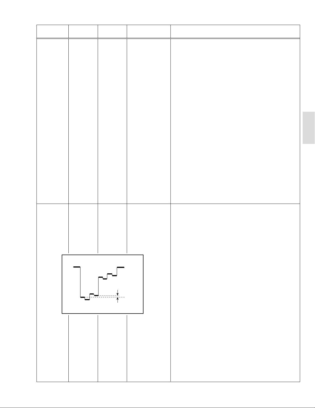
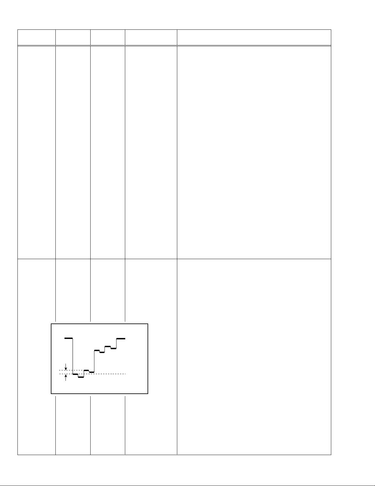
1. VER. SLOPE 1. Receive a PAL circle pattern signal of vertical frequency 50Hz.
2. Select 3. DEF from the SERVICE MENU.
3. Select 1. VER. SLOPE with the MENU &/^ key.
4. Set the initial setting value of 1. VER. SLOPE with the MENU –/+
key.
5. Adjust 1. VER. SLOPE to make “A = B” with the MENU –/+ key.
A
Blanking
line
B
3. VER. POSITION 6. Select 3. VER. POSITION with the MENU &/^ key.
7. Set the initial setting value of 3. VER. POSITION with the MENU
–/+ key.
8. Adjust 3. VER. POSITION to make “A = B” with the MENU –/+ key.
A
(to be continued)
B
No. 51901 7
Page 8
AV-2108TEE
PRESET ADJUSTMENT
Do not adjust 5. PRESET in the SERVICE MENU as it requires no adjustment.
•
[SUB MENU 5. PRESET]
Setting item Variable range Initial setting value
1 CB 0/1 0
2 ACL 0/1 0
3 MUS 0/1 0
4 MAT 0/1 0
5 FCO 0/1 0
6 BPS 0/1 0
7 IFLH 0/1 0
8 VID 0/1 0
9 STM 0/1 0
10 AFCW 0/1 0
11 VSW 0/1 0
12 FFI 0/1 0
13 AGC 00/10/01 10
14 CL 50 – 95 80
15 AKB 0/1 0
16 HBL 0/1 0
17 BKS 0/1 1
18 READ STATUS ——
19 VNR 00 – 63 25
8 No. 51901
Page 9
AV-2508TEE
SPECIFIC SERVICE INSTRUCTIONS [AV-2508TEE/B]
SETTING OF SYSTEM CONSTANT SET
Setting item Setting content
SYSTEM
COMB
TILT
TEXT
SUPER BASS
LANGUAGE
MSP
BILINGUAL
B/B SOUND
TUNER
MULTI TRIPLE
YES NO
YES NO
YES NO
YES NO
E/R/C E/R/A/F
E/F E/A
E/R E/C E/A/F
YES NO
YES NO
YES NO
MU MA
AV-25LS AV-25LS-AU
MULTI
NO
NO
ARABIC
E/R/C
PAN EURO NO
NO
YES
NO
NO
MU
Setting value
AV-25LH AV-25LX-AU AV-2508TEE AV-2508TEE/BAV-25X-A
AV-25LX
E/C E/R/A/F E/R/C E/R
NO
YES NO
RUSSIAN UKRANIAN
COLOUR AUTO
LOCK 1MHz
500KHz
250KHz
156.25KHz
31.25KHz
NOTE : (
***
YES NO
000 024
000 024
000 024
000 024
000 024
) is for Micon (IC1701) Part No. TDA9365N13S0518.
NO
020(040)
020(040)
020(040)
015(030)
015(030)
Table 1
020
020
020
015
015
YES NO
020(040)
020(040)
020(040)
015(030)
015(030)
(040)
(040)
(040)
(030)
(030)
18 No. 51901
Page 10

AV-2508TEE
SERVICE ADJUSTMENTS [AV-2508TEE/B]
VC (VIDEO/CHROMA) CIRCUIT ADJUSTMENT
The setting (adjustment) using the remote control unit is made on the basis of the initial setting values.
The setting values which adjust the screen to the optimum condition can be different from the initial setting values.
Do not change the initial setting values of the setting (adjustment) items not listed in “ADJUSTMENT”.
•
[SUB MENU 2. VC] : Do not adjust.
Setting (Adjustment) item Variable range
Initial setting value
PAL SECAM NTSC3.58 NTSC4.43 COMPONENT
1 CUTOFF(R/G) –7 — +8 0
2 DRIVE(R/G/B) –30 — +31 0
3 BRIGHT(COM./TV/V-1/V-2/V-3) –30 — +31 0/–18/0/0/0
4 CONT –30 — +31 –20 —
5 COLOUR –30 — +31 5 –3 –12 –6 +10
6 TINT (TV/VIDEO) –30 — +31 — — –12/+4 +1/+1 —
7 SHARP (TV/VIDEO) –30 — +31 –16/–2 —/0
8 YDELAY (TV/VIDEO/S) –8 — +7 0/+1/0 +5/+1/+1 0/+1/+1 +5/0/+1 —
Item
Adjustment
of WHITE
Measuring
instrument
Signal
generator
Test point Adjustment part Description
1. CUTOFF (R)
CUTOFF (G)
Note:
• Set PICTURE MODE (VSM) to “BRIGHT”.
BALANCE
(Low light)
Remote
control unit
SCREEN VR
[In HVT]
1. Receive a PAL black and white signal (colour off).
2. Select 2. VC from the SERVICE MENU.
3. Select 1. CUTOFF (R) and (G) with MENU &/^ key, and set each
value to initial setting value with the 4 and 7 keys, or 5 and 8 keys on
V/C
-
/+ : OPERATE
(R)
(G)
1. CUTOFF
50 Hz
MENU 89: SELECT
MENU
PAL
**
**
DISPLAY : EXIT
the remote control unit.
4. Press the 1 key on the remote control unit to produce a single hori-
zontal line.
5. Turn the SCREEN VR fully counterclockwise, then slowly turn it clockwise to where a red, blue or green colour is faintly visible.
6. Use the keys 4 and 7 or 5 and 8 on the remote control unit and
adjust the other 2 colours to where the single horizontal line appears white.
7. Turn the SCREEN VR to where the single horizontal line glows faintly.
8. Press the 2 key to return to 1. CUTOFF screen.
9. Press the DISPLAY key twice to return to the normal screen.
Setting (Adjustment) Variable Initial setting
Item range value
1. CUT OFF
R –7 — +8 0
G –7 — +8 0
H.LINE OFF
H.LINE ON
R. CUTOFF (
REMOTE CONTROL UNIT
12 3
4
8
)
56
G. CUTOFF (8)
AV-2508TEE
R. CUTOFF (
789
)
9
G.CUTOFF (
)
9
No. 51901 19
Page 11

AV-2508TEE
Item
Adjustment
of
SUB
COLOUR-I
Measuring
instrument
Remote
control unit
Test point Adjustment part Description
5. COLOUR
[Method of adjustment without measuring instrument]
Notes:
• Proceed to the following this adjustment after having completed the
adjustment of SUB CONT.
• Set PICTURE MODE (VSM) to “BRIGHT”.
– PAL COLOUR –
1. Receive a PAL broadcast.
2. Select 2. VC from the SERVICE MENU.
3. Select 5. COLOUR with the MENU &/^ key.
4. Set the initial setting value for PAL COLOUR with the MENU –/+ key.
5. If the colour is not best with the initial setting value, make fine ad-
justment until you get the best colour.
6. Press the DISPLAY key twice to return to the normal screen.
– SECAM COLOUR –
7. Receive a SECAM broadcast.
8. Press the COLOUR SYSTEM button on the remote control unit to
select the SECAM colour system.
9. Make fine adjustment of SECAM COLOUR in the same way as for
“PAL COLOUR”.
– NTSC 3.58 COLOUR –
10. Receive a NTSC 3.58MHz broadcast.
11. Press the COLOUR SYSTEM button on the remote control unit to
select the NTSC 3.58 colour system.
12. Make similar fine adjustment of NTSC 3.58 COLOUR in the same
way as for “PAL COLOUR”.
– NTSC 4.43 COLOUR –
When adjustment is done for NTSC 3.58 COLOUR, appropriate
values are automatically set for NTSC 4.43 COLOUR.
Adjustment
of SUB
COLOUR-II
Signal
generator
Oscilloscope
Remote
control unit
Cy
Y
W
TP-47G
TP-E (H)
[CRT
SOCKET
PWB]
Mg
G
5. COLOUR [Method of adjustment using measuring instrument]
Notes:
• Proceed to the following this adjustment after having completed the
adjustment of SUB CONT.
• Set PICTURE MODE (VSM) to “BRIGHT”.
– PAL COLOUR –
1. Receive a PAL colour bar signal (full field colour bar 75% white).
2. Select 2. VC from the SERVICE MENU.
3. Select 5. COLOUR with the MENU &/^ key.
4. Set the initial setting value of PAL COLOUR with the MENU –/+ key.
5. Connect the oscilloscope between TP-47G and TP-E.
B
R
(A)
(–)
0V
(+)
6.
Adjust PAL COLOUR to set the value (A) in the figure to +14V (V
W-G
– SECAM COLOUR –
7. Receive a SECAM colour bar signal (full field colour bar 75% white).
8. Press the COLOUR SYSTEM button on the remote control unit to
select the SECAM colour system.
9. Set the initial setting value of SECAM COLOUR with the MENU –/+ key.
).
10. Adjust SECAM COLOUR to set the value (A) in the figure to –3V
(VW-G).
– NTSC 3.58 COLOUR –
11. Receive a NTSC 3.58 colour bar signal (full field colour bar 75% white).
12. Press the COLOUR SYSTEM button on the remote control unit to
select the NTSC 3.58 colour system.
13. Set the initial setting value of NTSC 3.58 COLOUR with the MENU
–/+ key.
14. Adjust NTSC 3.58 COLOUR to set the value (A) in the figure to
+3V (VW-G).
– NTSC 4.43 COLOUR –
When adjustment is done for NTSC 3.58 COLOUR, appropriate
values are automatically set for NTSC 4.43 COLOUR.
20 No. 51901
Page 12

AV-2508TEE
Item
Adjustment
of
SUB TINT-I
Measuring
instrument
Remote
control unit
Test point Adjustment part Description
6. TINT [Method of adjustment without measuring instrument]
Notes:
• Proceed to the following this adjustment after having completed the
adjustment of SUB CONT.
• Set PICTURE MODE (VSM) to “BRIGHT”.
– NTSC 3.58 TINT –
1. Receive a NTSC 3.58 colour bar signal (full field colour bar 75%
white).
2. Press the COLOUR SYSTEM button on the remote control unit to
select the NTSC 3.58 colour system.
3. Select 2. VC from the SERVICE MENU.
4. Select 6. TINT with the MENU &/^ key.
5. Set the initial setting value of NTSC 3.58 with the MENU –/+ key.
6. If you cannot get the best tint with the initial setting value, make fine
adjustment until you get the best tint.
7. Press the DISPLAY key twice to return to the normal screen.
– NTSC 4.43 TINT –
When adjustment is done for NTSC 3.58 TINT, appropriate values are
automatically set for NTSC 4.43 TINT.
AV-2508TEE
Adjustment
of SUB
SUB TINT-II
Signal
generator
Oscilloscope
Remote
control unit
(B)
Cy
W
Y
TP-47G
TP-E (H)
[CRT
SOCKET
PWB]
B
Mg
R
G
6. TINT [Method of adjustment using measuring instrument]
Notes:
• Proceed to the following this adjustment after having completed the
adjustment of SUB CONT.
• Set PICTURE MODE (VSM) to “BRIGHT”.
– NTSC 3.58 TINT –
1. Receive a NTSC 3.58 colour bar signal (full field colour bar 75%
white).
2. Press the COLOUR SYSTEM button on the remote control unit to
select the NTSC 3.58 colour system.
3. Select 2. VC from the SERVICE MENU.
4. Select 6. TINT with the MENU &/^ key.
5. Set the initial setting value of NTSC 3.58 with the MENU –/+ key.
6. Connect the oscilloscope between TP-47G and TP-E.
(–)
0V
(+)
7.
Adjust NTSC 3.58 TINT to set the value (B) in the figure to +3V (V
8. Press the DISPLAY key twice to return to the normal screen.
– NTSC 4.43 TINT –
When adjustment is done for NTSC 3.58 TINT, appropriate values are
automatically set for NTSC 4.43 TINT.
W-cy
).
No. 51901 21
Page 13

AV-2508TEE
DEFLECTION CIRCUIT ADJUSTMENT
The setting (adjustment) using the remote control unit is made on the basis of the initial setting values.
The setting values which adjust the screen to the optimum condition can be different from the initial setting values.
Note:
Proceed to the following this adjustment after having completed the adjustments of SUB BRIGHT and SUB CONT.
[SUB MENU 3. DEF]
Setting
(Adjustment)
item
Variable range
50Hz 60Hz
4:3
1. VER. SLOPE –31 — +31 0 0 —— —
2. VER. HEIGHT –31 — +31 +31 +31 0 0 —
3. VER. POSITION –31 — +31 0 0 —— —
4. VER. SCURVE –31 — +31 –21 –2 —— —
5. HOR. POSITION –31 — +31 0 0 —— +7
6. HOR. WIDTH –31 — +31 0 0 —— —
7. EW-PIN –31 — +31 0 0 0 0 —
8. EW-TRAPEZ –31 — +31 0 0 —— —
9. UP CORNER –31 — +31 0 0 0 0 —
10. DW CORNER –31 — +31 0 0 0 0 —
11. HOR. PARALL –31 — +31 0 0 —— —
12. HOR. BOW –31 — +31 0 0 —— —
13. V.ZOOM –31 — +31 0 0 0 0 —
Initial setting value
COMPRESS(16:9)
50Hz 60Hz
COMPONENT
DVD(50Hz/60Hz)
[fv : 50Hz mode]
Item
Adjustment
of
VER. SLOPE
Adjustment
of
VER.POSITION
Measuring
instrument
Signal
generator
Remote
control unit
Signal
generator
Remote
control unit
Test point Adjustment part Description
1. VER. SLOPE 1. Receive a PAL circle pattern signal of vertical frequency 50Hz.
2. Select 3. DEF from the SERVICE MENU.
3. Select 1. VER. SLOPE with the MENU &/^ key.
4. Set the initial setting value of 1. VER. SLOPE with the MENU –/+
key.
5. Adjust 1. VER. SLOPE to make “A = B” with the MENU –/+ key.
A
Blanking
line
B
3. VER. POSITION 6. Select 3. VER. POSITION with the MENU &/^ key.
7. Set the initial setting value of 3. VER. POSITION with the MENU
–/+ key.
8. Adjust 3. VER. POSITION to make “A = B” with the MENU –/+ key.
A
(to be continued)
B
22 No. 51901
Page 14

AV-2508TEE
PRESET ADJUSTMENT
Do not adjust 5. PRESET in the SERVICE MENU as it requires no adjustment.
•
[SUB MENU 5. PRESET]
Setting item Variable range Initial setting value
1 CB 0/1 0
2 ACL 0/1 0
3 MUS 0/1 0
4 MAT 0/1 0
5 FCO 0/1 0
6 BPS 0/1 0
7 IFLH 0/1 0
8 VID 0/1 0
9 STM 0/1 0
10 AFCW 0/1 0
11 VSW 0/1 0
12 FFI 0/1 0
13 AGC 00/10/01 10
14 CL 50 – 95 83
15 AKB 0/1 0
16 HBL 0/1 0
17 BKS 0/1 1
18 READ STATUS ——
19 VNR 00 – 63 25
AV-2508TEE
No. 51901 23
Page 15

AV-2908TEE
SPECIFIC SERVICE INSTRUCTIONS [AV-2908TEE/B]
SETTING OF SYSTEM CONSTANT SET
Setting item Setting content
SYSTEM
COMB
TILT
TEXT
SUPER BASS
LANGUAGE
MSP
BILINGUAL
B/B SOUND
TUNER
MULTI TRIPLE
YES NO
YES NO
YES NO
YES NO
E/R/C E/R/A/F
E/F E/A
E/R E/C E/A/F
YES NO
YES NO
YES NO
MU MA
AV-29LS AV-29LS-AU
MULTI
YES
YES
ARABIC
E/R/C
PAN EURO NO
NO
YES
NO
NO
MU
Setting value
AV-29LH AV-29LX-AU AV-2908TEE AV-2908TEE/BAV-29X-A
AV-29LX
E/C E/R/A/F E/R/C E/R
NO
YES NO
RUSSIAN UKRANIAN
COLOUR AUTO
LOCK 1MHz
500KHz
250KHz
156.25KHz
31.25KHz
NOTE : (
) is for Micon (IC1701) Part No. TDA9365N13S0518.
***
YES NO
000 024
000 024
000 024
000 024
000 024
NO
020(040)
020(040)
020(040)
015(030)
015(030)
Table 1
020
020
020
015
015
YES NO
020(040)
020(040)
020(040)
015(030)
015(030)
(040)
(040)
(040)
(030)
(030)
30 No. 51901
Page 16

AV-2908TEE
SERVICE ADJUSTMENTS [AV-2908TEE/B]
B1 POWER SUPPLY
Item
Measuring
instrument
Test point Adjustment part Description
Check of
B1 POWER
SUPPLY
Signal
Generator
DC Voltmeter
FOCUS ADJUSTMENT
Item
Adjustment
of FOCUS
Measuring
instrument
Signal
generator
B1 (pin 1)
GND (pin 5)
[CN00S
connector]
Test point Adjustment part Description
FOCUS VR1,2
[In HVT]
1. Receive a black and white signal.
2. Connect a DC voltmeter between B1 and GND
(between pins 1 and 5 of the connector CN00S).
3. Make sure that the voltage is DC134.5 ± 2V.
Notes:
• Proceed to the following this adjustment after having completed the
adjustments of B1 POWER SUPPLY, SUB BRIGHT and SUB CONT.
• Set PICTURE MODE (VSM) to “BRIGHT”.
• The final adjustment of CONVERGENCE must be done after the
FOCUS adjustment. (CONVERGENCE is changed by FOCUS adjustment.)
When makes difference by FOCUS adjustment, should be reconfirming
PURITY adjustment.
1. Receive a cross-hatch signal.
2. While looking at the screen centre, adjust the FOCUS VR2 (F2) so
that the horizontal lines will be clear and in fine detail.
3. Adjust the FOCUS VR1 (F1) so that the vertical lines will be clear
and in fine detail.
4. Make sure that the picture is in focus even when the screen gets
darkened.
AV-2908TEE
IF CIRCUIT ADJUSTMENT
Item
Adjustment
of VCO (CW)
Adjustment
of DELAY
POINT
Setting
(Adjustment time)
DELAY POINT
(AGC TAKE-OVER)
Measuring
instrument
Remote
control unit
VCO (CW)
TOO HIGH
ABOVE REFERENCE
BELOW REFERENCE
TOO LOW
Remote
control unit
Test point Adjustment part Description
. MHz
DISPLAY : EXIT
NTSC 3.58 22
OTHERS 15
VCO (CW)
fv
YELLOW
DELAY POINT
(AGC TAKE-OVER)
Initial setting value
Note:
• Under normal conditions, no adjustment is required.
1. Select 1. IF from the SERVICE MENU.
2. Select 1. VCO by pressing the 1 key on the remote control unit.
3. Receive a broadcast signal.
4. Check the characters colour of the BELOW REFERENCE displayed
to yellow.
5. Press the DISPLAY key three times to return to normal screen.
1. Receive a black and white broadcast signal (colour off).
2. Select 1. IF from the SERVICE MENU.
3. Select 2. DELAY POINT by pressing the 2 key on the remote con-
trol unit.
4. Adjust the MENU –/+ key in order to eliminate any noise or beat
from the image. Any increase above the initial value produces noise
and any decrease below it produces beat.
5. Press the DISPLAY key three times to return to the normal screen.
6. Turn to other channels and make sure that there are no irregularities.
No. 51901 31
Page 17

AV-2908TEE
VC (VIDEO/CHROMA) CIRCUIT ADJUSTMENT
The setting (adjustment) using the remote control unit is made on the basis of the initial setting values.
The setting values which adjust the screen to the optimum condition can be different from the initial setting values.
Do not change the initial setting values of the setting (adjustment) items not listed in “ADJUSTMENT”.
•
[SUB MENU 2. VC] : Do not adjust.
Setting (Adjustment) item Variable range
Initial setting value
PAL SECAM NTSC3.58 NTSC4.43 COMPONENT
1 CUTOFF(R/G) –7 — +8 0
2 DRIVE(R/G/B) –32 — +31 0
3 BRIGHT(COM./TV/V-1/V-2/V-3) –32 — +31 –1/–16/0/0/0
4 CONT –32 — +31 0 —
5 COLOUR –32 — +31 –5 –3 –12 +1 +10
6 TINT (TV/VIDEO) –32 — +31 ——–15/+6 +1/+1 —
7 SHARP (TV/VIDEO) –32 — +31 –24/–10 —/0
8 YDELAY (TV/VIDEO/S) –8 — +7 0/+1/0 +5/+1/+1 0/+1/+1 +5/0/+1 —
Item
Adjustment
of WHITE
Measuring
instrument
Signal
generator
Test point Adjustment part Description
1. CUTOFF (R)
CUTOFF (G)
Note:
• Set PICTURE MODE (VSM) to “BRIGHT”.
BALANCE
(Low light)
Remote
control unit
SCREEN VR
[In HVT]
1. Receive a PAL black and white signal (colour off).
2. Select 2. VC from the SERVICE MENU.
3. Select 1. CUTOFF (R) and (G) with MENU &/^ key, and set each
value to initial setting value with the 4 and 7 keys, or 5 and 8 keys on
V/C
1. CUTOFF
50 Hz
MENU 89: SELECT
MENU
(R)
(G)
-
/+ : OPERATE
PAL
**
**
DISPLAY : EXIT
the remote control unit.
4. Press the 1 key on the remote control unit to produce a single hori-
zontal line.
5. Turn the SCREEN VR fully counterclockwise, then slowly turn it clockwise to where a red, blue or green colour is faintly visible.
6. Use the keys 4 and 7 or 5 and 8 on the remote control unit and
adjust the other 2 colours to where the single horizontal line appears white.
7. Turn the SCREEN VR to where the single horizontal line glows faintly.
8. Press the 2 key to return to 1. CUTOFF screen.
9. Press the DISPLAY key twice to return to the normal screen.
Setting (Adjustment) Variable Initial setting
Item range value
1. CUT OFF
R –7 — +8 0
G –7 — +8 0
H.LINE OFF
H.LINE ON
R. CUTOFF (
REMOTE CONTROL UNIT
12 3
4
8
)
56
G. CUTOFF (8)
789
R. CUTOFF (
)
9
G.CUTOFF (
)
9
32 No. 51901
Page 18

AV-2908TEE
DEFLECTION CIRCUIT ADJUSTMENT
The setting (adjustment) using the remote control unit is made on the basis of the initial setting values.
The setting values which adjust the screen to the optimum condition can be different from the initial setting values.
Note:
Proceed to the following this adjustment after having completed the adjustments of SUB BRIGHT and SUB CONT.
[SUB MENU 3. DEF]
Setting
(Adjustment)
item
Variable range
50Hz 60Hz
4:3
1. VER. SLOPE –31 — +31 +3 0 —— —
2. VER. HEIGHT –31 — +31 +31 0 –29 –24 —
3. VER. POSITION –31 — +31 +2 –1 —— —
4. VER. SCURVE –31 — +31 –21 0 —— —
5. HOR. POSITION –31 — +31 –4+7—— +7
6. HOR. WIDTH –31 — +31 +11 –1 —— —
7. EW-PIN –31 — +31 –11 –1 –13 –12 —
8. EW-TRAPEZ –31 — +31 0 0 —— —
9. UP CORNER –31 — +31 –25 0 0 0 —
10. DW CORNER –31 — +31 –25 0 0 0 —
11. HOR. PARALL –31 — +31 0 0 —— —
12. HOR. BOW –31 — +31 0 0 —— —
13. V.ZOOM –31 — +31 –1 –1 +14 +6 —
Initial setting value
COMPRESS(16:9)
50Hz 60Hz
COMPONENT
DVD(50Hz/60Hz)
[fv : 50Hz mode]
Item
Adjustment
of
VER. SLOPE
Adjustment
of
VER.POSITION
Measuring
instrument
Signal
generator
Remote
control unit
Signal
generator
Remote
control unit
Test point Adjustment part Description
AV-2908TEE
1. VER. SLOPE 1. Receive a PAL circle pattern signal of vertical frequency 50Hz.
2. Select 3. DEF from the SERVICE MENU.
3. Select 1. VER. SLOPE with the MENU &/^ key.
4. Set the initial setting value of 1. VER. SLOPE with the MENU –/+
key.
5. Adjust 1. VER. SLOPE to make “A = B” with the MENU –/+ key.
A
Blanking
line
B
3. VER. POSITION 6. Select 3. VER. POSITION with the MENU &/^ key.
7. Set the initial setting value of 3. VER. POSITION with the MENU
–/+ key.
8. Adjust 3. VER. POSITION to make “A = B” with the MENU –/+ key.
A
(to be continued)
B
No. 51901 33
Page 19

AV-2908TEE
[fv : 60Hz mode]
Item
Measuring
instrument
Test point Adjustment part Description
Adjustment
of
VER. SLOPE
Adjustment
of
VER.POSITION
Signal
generator
Remote
control unit
Signal
generator
Remote
control unit
1. VER. SLOPE 1. Receive a NTSC circle pattern signal of vertical frequency 60Hz.
2. Select 3. DEF from the SERVICE MENU.
3. Select 1. VER. SLOPE with the MENU &/^ key.
4. Set the initial setting value of 1. VER. SLOPE with the MENU –/+
key.
5. Adjust 1. VER. SLOPE to make “A = B” with the MENU –/+ key.
A
Blanking
line
B
3. VER. POSITION 6. Select 3. VER. POSITION with the MENU &/^ key.
7. Set the initial setting value of 3. VER. POSITION with the MENU
–/+ key.
8. Adjust 3. VER. POSITION to make “A = B” with the MENU –/+ key.
Adjustment
of
V. ZOOM
Screen
size
91%
Signal
generator
Remote
control unit
Screen size
A
B
2. VER. HEIGHT
13. V. ZOOM
Picture
size
100%
9. Receive a NTSC cross-hatch signal.
10. Select 2. VER. HEIGHT with the MENU &/^ key.
11. Set the initial setting value of 2. VER. HEIGHT with the MENU –/+
key.
12. Select 13. V. ZOOM with the MENU &/^ key.
13. Set the initial setting value of 13. V. ZOOM with the MENU –/+ key.
14. Adjust 13. V. ZOOM and make the vertical screen size 91% of the
picture size with the MENU –/+ key.
(to be continued)
Picture size 100%
34 No. 51901
Page 20

AV-2908TEE
Item
Adjustment
of
HOR. POSITION
Adjustment
of
HOR. WIDTH
Measuring
instrument
Signal
Test point Adjustment part Description
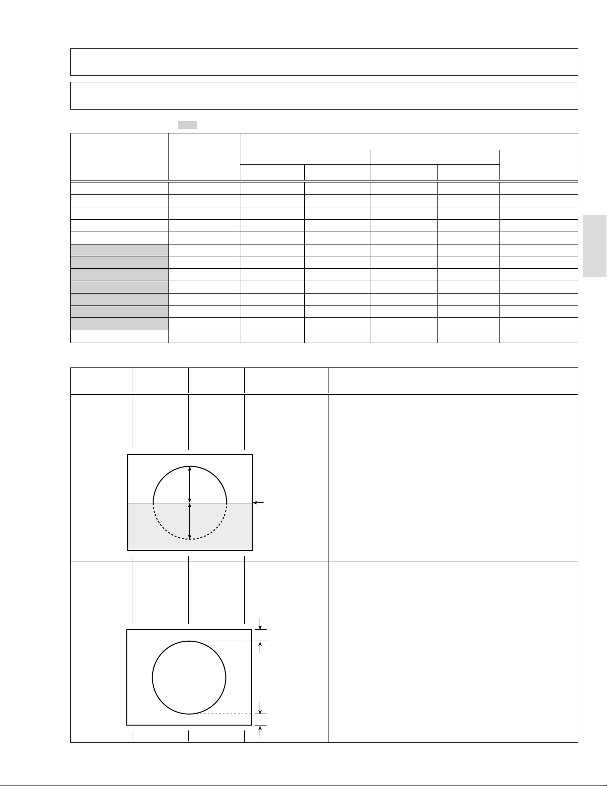
5. HOR. POSITION 15. Receive a NTSC circle pattern signal.
generator
Remote
control unit
CD
Signal
6. HOR. WIDTH 19. Receive a NTSC cross-hatch signal.
generator
Remote
control unit
Screen size 91%
16. Select 5. HOR. POSITION with the MENU &/^ key.
17. Set the initial setting value of 5. HOR. POSITION with the MENU
–/+ key.
18. Adjust 5. HOR. POSITION to make “C=D” with the MENU –/+ key.
20. Select 6. HOR. WIDTH with the MENU &/^ key.
21. Set the initial setting value of 6. HOR. WIDTH with the MENU –/+
key.
22. Adjust 6. HOR. WIDTH and make the horizontal screen size 91%
of the picture size with the MENU –/+ key.
Screen
Adjustment
of
EW-PIN
size
91%
Signal
generator
Remote
control unit
AV-2908TEE
Picture
size
100%
Picture size 100%
7. EW-PIN 23. Select 7. EW-PIN with the MENU &/^ key.
24. Set the initial setting value of 7. EW-PIN with the MENU –/+ key.
25. Adjust 7. EW-PIN so that the first vertical lines at the left and right
edges on the screen are straight.
Straight
(to be continued)
No. 51901 35
Page 21

AV-2908TEE
Item
Adjustment
of
EW-TRAPEZ
Adjustment
of
VER. SCURVE
Measuring
instrument
Signal
generator
Remote
control unit
Signal
generator
Remote
control unit
Test point Adjustment part Description
8. EW-TRAPEZ 26. Select 8. EW-TRAPEZ with the MENU &/^ key.
27. Set the initial setting value of 8. EW-TRAPEZ with the MENU –/+
Parallel
key.
28. Adjust 8. EW-TRAPEZ so that the vertical lines at the left and right
edges on the screen are in parallel.
4. VER. SCURVE 29. Select 4. VER. SCURVE with the MENU &/^ key.
30.Set the initial setting value of 4. VER. SCURVE with the MENU –/+
key.
31. Adjust 4. VER. SCURVE so that the spaces of each line on TOP,
CENTRE and BOTTOM become uniform.
TOP
Adjustment
of
UP CORNER
and
DW CORNER
Adjustment
of
HOR. PARALL
Adjustment
of
HOR. BOW
Signal
generator
Remote
control unit
Signal
generator
Remote
control unit
Signal
generator
Remote
control unit
CENTRE
BOTTOM
9. UP CORNER
10. DW CORNER
32. Select 9. UP CORNER with the MENU &/^ key.
33. Set the initial setting value of 9. UP CORNER with the MENU –/+
key.
34. Sekect 10. DW CORNER with the MENU &/^ key.
35. Set the initial setting value of 10. DW CORNER with the MENU –/+
key.
36. Adjust 9. UP CORNER and 10. DW CORNER so that the vertical
lines at the four corners on the screen are straight.
11. HOR. PARALL 37. Select 11. HOR. PARALL with the MENU &/^ key.
38. Set the initial setting value of 11. HOR. PARALL with the MENU
–/+ key.
39. Adjust 11. HOR. PARALL to optimize the parallelogram distortion.
12. HOR. BOW 40. Select 12. HOR. BOW with the MENU &/^ key.
Straight
41. Set the initial setting value of Select 12. HOR. BOW with the MENU
–/+ key.
42. Adjust 12. HOR. BOW to optimize the horizontal arc distortion.
43. Press the DISPLAY key twice to return to the normal screen.
36 No. 51901
Page 22

AV-2908TEE
PRESET ADJUSTMENT
Do not adjust 5. PRESET in the SERVICE MENU as it requires no adjustment.
•
[SUB MENU 5. PRESET]
Setting item Variable range Initial setting value
1 CB 0/1 0
2 ACL 0/1 0
3 MUS 0/1 0
4 MAT 0/1 0
5 FCO 0/1 0
6 BPS 0/1 0
7 IFLH 0/1 0
8 VID 0/1 0
9 STM 0/1 0
10 AFCW 0/1 0
11 DIDEOSW 0/1 0
12 FFI 0/1 0
13 AGC 00/10/01 10
14 CL 50 – 95 77
15 AKB 0/1 0
16 HBL 0/1 0
17 BKS 0/1 1
18 READ STATUS ——
19 VNR 00 – 63 25
AV-2908TEE
No. 51901 37
Page 23

SPECIFIC SERVICE INSTRUCTIONS [AV-3408TEE/B]
SETTING OF SYSTEM CONSTANT SET
AV-3408TEE
Setting item Setting content
SYSTEM MULTI
COMB
TILT
TEXT
SUPER BASS
LANGUAGE
MSP
BILINGUAL
B/B SOUND
TUNER
MULTI TRIPLE
PA L
YES NO
YES NO
YES NO
YES NO
E/R/C E/R/A/F
E/F E/A
E/R E/C E/A/F
YES NO
YES NO
YES NO
MU MA
AV-34LS AV-34LS-AU AV-34LXAV-34LH AV-3408TEE AV-3408TEE/BAV-34X-A
YES
YES
ARABIC
NO
E/R/C
YES
NO
NO
MU
PAN EURO NO
E/C E/R/A/F E/R
Setting value
NO
YES
RUSSIAN UKRANIAN
NO
COLOUR AUTO
LOCK 1MHz
500KHz
250KHz
156.25KHz
31.25KHz
NOTE : (
***
YES NO
000 024
000 024
000 024
000 024
000 024
) is for Micon (IC1701) Part No. TDA9365N13S0518.
NO
020(040)
020(040)
020(040)
015(030)
015(030)
Table 1
020
020
020
015
015
YES
NO
020(040)
020(040)
020(040)
015(030)
015(030)
(040)
(040)
(040)
(030)
(030)
AV-3408TEE
No. 51901 49
Page 24

AV-3408TEE
SERVICE ADJUSTMENTS [AV-3408TEE/B]
ADJUSTMENTS
B1 POWER SUPPLY
Item
Measuring
instrument
Test point Adjustment part Description
Check of
B1 POWER
SUPPLY
Signal
Generator
DC Voltmeter
FOCUS ADJUSTMENT
Item
Adjustment
of FOCUS
Measuring
instrument
Signal
generator
B1 (pin 1)
GND (pin 5)
[CN00S
connector]
Test point Adjustment part Description
FOCUS VR1,2
[In HVT]
1. Receive a black and white signal.
2. Connect a DC voltmeter between B1 and GND
(between pins 1 and 5 of the connector CN00S).
3. Make sure that the voltage is DC134.5 ± 2V.
Notes:
• Proceed to the following this adjustment after having completed the
adjustments of B1 POWER SUPPLY, SUB BRIGHT and SUB CONT.
• Set PICTURE MODE (VSM) to “BRIGHT”.
• The final adjustment of CONVERGENCE must be done after the
FOCUS adjustment. (CONVERGENCE is changed by FOCUS adjustment.)
When makes difference by FOCUS adjustment, should be reconfirming
PURITY adjustment.
1. Receive a cross-hatch signal.
2. While looking at the screen centre, adjust the FOCUS VR2 (F2) so
that the horizontal lines will be clear and in fine detail.
3. Adjust the FOCUS VR1 (F1) so that the vertical lines will be clear
and in fine detail.
4. Make sure that the picture is in focus even when the screen gets
darkened.
IF CIRCUIT ADJUSTMENT
Item
Adjustment
of VCO (CW)
Adjustment
of DELAY
POINT
Setting
(Adjustment time)
DELAY POINT
(AGC TAKE-OVER)
Measuring
instrument
Remote
control unit
VCO (CW)
TOO HIGH
ABOVE REFERENCE
BELOW REFERENCE
TOO LOW
Remote
control unit
Test point Adjustment part Description
. MHz
DISPLAY : EXIT
NTSC 3.58 22
OTHERS 15
VCO (CW)
fv
YELLOW
DELAY POINT
(AGC TAKE-OVER)
Initial setting value
Note:
• Under normal conditions, no adjustment is required.
1. Select 1. IF from the SERVICE MENU.
2. Select 1. VCO by pressing the 1 key on the remote control unit.
3. Receive a broadcast signal.
4. Check the characters colour of the BELOW REFERENCE displayed
to yellow.
5. Press the DISPLAY key three times to return to normal screen.
1. Receive a black and white broadcast signal (colour off).
2. Select 1. IF from the SERVICE MENU.
3. Select 2. DELAY POINT by pressing the 2 key on the remote con-
trol unit.
4. Adjust the MENU –/+ key in order to eliminate any noise or beat
from the image. Any increase above the initial value produces noise
and any decrease below it produces beat.
5. Press the DISPLAY key three times to return to the normal screen.
6. Turn to other channels and make sure that there are no irregulari-
ties.
50 No. 51901
Page 25

VC (VIDEO/CHROMA) CIRCUIT ADJUSTMENT
The setting (adjustment) using the remote control unit is made on the basis of the initial setting values.
The setting values which adjust the screen to the optimum condition can be different from the initial setting values.
Do not change the initial setting values of the setting (adjustment) items not listed in “ADJUSTMENT”.
•
[SUB MENU 2. VC] : Do not adjust.
AV-3408TEE
Setting (Adjustment) item Variable range
Initial setting value
PAL SECAM NTSC3.58 NTSC4.43 COMPONENT
1 CUTOFF(R/G) –7 — +8 0 0/+3
2 DRIVE(R/G/B) –32 — +31 0
3 BRIGHT(COM./TV/V-1/V-2/V-3) –32 — +31 –1/–16/0/0/0
4 CONT –32 — +31 0 —
5 COLOUR –32 — +31 –5 –3 –12 +1 +10
6 TINT (TV/VIDEO) –32 — +31 ——–15/+6 +1/+1 —
7 SHARP (TV/VIDEO) –32 — +31 –24/–10 —/0
8 YDELAY (TV/VIDEO/S) –8 — +7 0/+1/0 +5/+1/+1 0/+1/+1 +5/0/+1 —
Item
Adjustment
of WHITE
Measuring
instrument
Signal
generator
Test point Adjustment part Description
1. CUTOFF (R)
CUTOFF (G)
Note:
• Set PICTURE MODE (VSM) to “BRIGHT”.
BALANCE
(Low light)
Remote
control unit
SCREEN VR
[In HVT]
1. Receive a PAL black and white signal (colour off).
2. Select 2. VC from the SERVICE MENU.
3. Select 1. CUTOFF (R) and (G) with MENU &/^ key, and set each
value to initial setting value with the 4 and 7 keys, or 5 and 8 keys on
V/C
1. CUTOFF
50 Hz
MENU 89: SELECT
MENU
(R)
(G)
-
/+ : OPERATE
PAL
**
**
DISPLAY : EXIT
the remote control unit.
4. Press the 1 key on the remote control unit to produce a single hori-
zontal line.
5. Turn the SCREEN VR fully counterclockwise, then slowly turn it clockwise to where a red, blue or green colour is faintly visible.
6. Use the keys 4 and 7 or 5 and 8 on the remote control unit and
adjust the other 2 colours to where the single horizontal line appears white.
7. Turn the SCREEN VR to where the single horizontal line glows faintly.
8. Press the 2 key to return to 1. CUTOFF screen.
9. Press the DISPLAY key twice to return to the normal screen.
Setting (Adjustment) Variable Initial setting
Item range value
1. CUT OFF
R –7 — +8 0
G –7 — +8 0
H.LINE OFF
H.LINE ON
R. CUTOFF (
REMOTE CONTROL UNIT
12 3
4
8
)
56
G. CUTOFF (8)
AV-3408TEE
R. CUTOFF (
789
)
9
G.CUTOFF (
)
9
No. 51901 51
Page 26

AV-3408TEE
PRESET ADJUSTMENT
Do not adjust 5. PRESET in the SERVICE MENU as it requires no adjustment.
•
[SUB MENU 5. PRESET]
Setting item Variable range Initial setting value
1 CB 0/1 0
2 ACL 0/1 0
3 MUS 0/1 0
4 MAT 0/1 0
5 FCO 0/1 0
6 BPS 0/1 0
7 IFLH 0/1 0
8 VID 0/1 0
9 STM 0/1 0
10 AFCW 0/1 0
11 VSW 0/1 0
12 FFI 0/1 0
13 AGC 00/10/01 10
14 CL 50 – 95 80
15 AKB 0/1 0
16 HBL 0/1 0
17 BKS 0/1 1
18 READ STATUS ——
19 VNR 00 – 63 25
52 No. 51901
Page 27

PATTERN DIAGRAMS [AV-3408TEE/B]
CRT SOCKET PWB PATTERN (CKF1476-CH2-1)
Pattern diagram is the same as for AV-2908TEE/B. Refer to page 38.
FRONT CONTROL PWB PATTERN (CKF1477-CH2-1)
Pattern diagram is the same as for AV-2908TEE/B. Refer to page 39.
AV-3408TEE
AV-3408TEE
No. 51901 53
Page 28

VICTOR COMPANY OF JAPAN, LIMITED
HOME AV NETWORK BUSINESS UNIT 12, 3-chome, Moriya-cho, kanagawa-ku, Yokohama, kanagawa-prefecture, 221-8528, Japan
AV2108TEEB-H #4
AV2508TEEB-H #4
AV2908TEEB-H #4
AV3408TEEB-H #4
Printed in Japan
VP0109
SW
 Loading...