

Page 1
AV-2108TEE AV-2908TEE
AV-2508TEE AV-3408TEE
SERVICE MANUAL
COLOUR TELEVISION
BASIC CHASSIS
CH
AV-2108TEE
AV-2508TEE
POWER
DISPLAY
MENU
CHANNEL VOLUME
SYSTEM
SOUND MUTING
COLOUR
TV/VIDEO
123
456
PICTURE MODE
7809
RETURN
CHANNEL SCAN
-/--
OFF TIMER
TV/TEXT
ECO SENSOR
TEXT
REVEAL HOLD INDEX STORE
MODE SIZE SUBPAGE CANCEL
RM-C355 REMOTE CONTROL UNIT
RM-C355-1C
/B
/B
AV-2908TEE
AV-3408TEE
/B
/B
Regarding service information other than these sections, refer to the AV-2108TEE service
manual (No. 51849), AV-2508TEE service manual (No. 51848), AV-2908TEE service manual
(No. 51839) and AV-3408TEE service manual (No.51854).
Also, be sure to note important safety precautions provided in the service manual.
COPYRIGHT © 2001 VICTOR COMPANY OF JAPAN, LTD.
No. 51901
Sep. 2001
Page 2

AV-2108TEE AV-2908TEE
AV-2508TEE AV-3408TEE
CONTENTS
a SPECIFIC SERVICE INSTRUCTIONS [AV-2108TEE/B] ......................................................................... 3
a SERVICE ADJUSTMENTS [AV-2108TEE/B] .......................................................................................... 4
a PARTS LIST [AV-2108TEE/B] ................................................................................................................ 9
a SPECIFIC SERVICE INSTRUCTIONS [AV-2508TEE/B] ....................................................................... 18
a SERVICE ADJUSTMENTS [AV-2508TEE/B] ........................................................................................ 19
a PARTS LIST [AV-2508TEE/B] ............................................................................................................... 24
a SPECIFIC SERVICE INSTRUCTIONS [AV-2908TEE/B] ....................................................................... 30
a SERVICE ADJUSTMENTS [AV-2908TEE/B] ........................................................................................ 31
a PATTERN DIAGRAMS [AV-2908TEE/B] ............................................................................................... 38
a PARTS LIST [AV-2908TEE/B] ............................................................................................................... 40
a SPECIFIC SERVICE INSTRUCTIONS [AV-3408TEE/B] ....................................................................... 49
a SERVICE ADJUSTMENTS [AV-3408TEE/B] ........................................................................................ 50
a PATTERN DIAGRAMS [AV-3408TEE/B] ............................................................................................... 53
a PARTS LIST [AV-3408TEE/B] ............................................................................................................... 54
2 No. 51901
Page 3
AV-2108TEE
SPECIFIC SERVICE INSTRUCTIONS [AV-2108TEE/B]
SETTING OF SYSTEM CONSTANT SET
Setting item Setting content
AV-21LS AV-21LS-AU AV-21LXAV-21LH AV-2108TEE AV-2108TEE/BAV-21X-A
Setting value
SYSTEM
COMB
TILT
TEXT
SUPER BASS
LANGUAGE
MSP
BILINGUAL
B/B SOUND
TUNER
COLOUR AUTO
LOCK 1MHz
MULTI TRIPLE
YES NO
YES NO
YES NO
YES NO
E/R/C E/R/A/F
E/F E/A
E/R E/C E/A/F
YES NO
YES NO
YES NO
MU MA
YES NO
000 024
MULTI
NO
NO
ARABIC
NO
E/R/C
YES
NO
NO
MU
NO
020(040)
PAN EURO NO
E/C E/R/A/F E/R
020
NO
YES
YES
RUSSIAN UKRANIAN
NO
NO
020(040)
(040)
AV-2108TEE
500KHz
250KHz
156.25KHz
31.25KHz
NOTE : (
000 024
000 024
000 024
000 024
) is for Micon (IC1701) Part No. TDA9365N13S0518.
***
020(040)
020(040)
015(030)
015(030)
Table 1
020
020
015
015
020(040)
020(040)
015(030)
015(030)
(040)
(040)
(030)
(030)
No. 51901 3
Page 4
AV-2108TEE
SERVICE ADJUSTMENTS [AV-2108TEE/B]
VC (VIDEO/CHROMA) CIRCUIT ADJUSTMENT
The setting (adjustment) using the remote control unit is made on the basis of the initial setting values.
The setting values which adjust the screen to the optimum condition can be different from the initial setting values.
Do not change the initial setting values of the setting (adjustment) items not listed in “ADJUSTMENT”.
•
[SUB MENU 2. VC] : Do not adjust.
Setting (Adjustment) item Variable range
Initial setting value
PAL SECAM NTSC3.58 NTSC4.43 COMPONENT
1 CUTOFF(R/G) –7 — +8 0
2 DRIVE(R/G/B) –30 — +31 0
3 BRIGHT(COM./TV/V-1/V-2/V-3) –30 — +31 0/–18/0/0/0
4 CONT –30 — +31 –20 —
5 COLOUR –30 — +31 –5 –3 –12 –2 +10
6 TINT (TV/VIDEO) –30 — +31 — — –15/+4 +1/+1 —
7 SHARP (TV/VIDEO) –30 — +31 –16/–2 –/0
8 YDELAY (TV/VIDEO/S) –8 — +7 0/+1/0 +5/+1/+1 0/+1/+1 +5/0/+1 —
Item
Adjustment
of WHITE
Measuring
instrument
Signal
generator
Test point Adjustment part Description
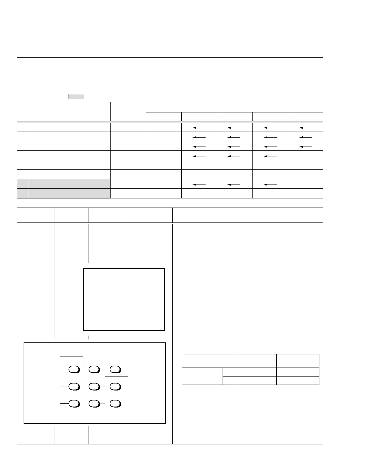
1. CUTOFF (R)
CUTOFF (G)
Note:
• Set PICTURE MODE (VSM) to “BRIGHT”.
BALANCE
(Low light)
Remote
control unit
SCREEN VR
[In HVT]
1. Receive a PAL black and white signal (colour off).
2. Select 2. VC from the SERVICE MENU.
3. Select 1. CUTOFF (R) and (G) with MENU &/^ key, and set each
value to initial setting value with the 4 and 7 keys, or 5 and 8 keys on
V/C
1. CUTOFF
50 Hz
MENU 89: SELECT
MENU
(R)
(G)
-
/+ : OPERATE
PAL
**
**
DISPLAY : EXIT
the remote control unit.
4. Press the 1 key on the remote control unit to produce a single hori-
zontal line.
5. Turn the SCREEN VR fully counterclockwise, then slowly turn it clockwise to where a red, blue or green colour is faintly visible.
6. Use the keys 4 and 7 or 5 and 8 on the remote control unit and
adjust the other 2 colours to where the single horizontal line appears white.
7. Turn the SCREEN VR to where the single horizontal line glows faintly.
8. Press the 2 key to return to 1. CUTOFF screen.
9. Press the DISPLAY key twice to return to the normal screen.
Setting (Adjustment) Variable Initial setting
Item range value
1. CUT OFF
R –7 — +8 0
G –7 — +8 0
H.LINE OFF
H.LINE ON
R. CUTOFF (
REMOTE CONTROL UNIT
12 3
4
8
)
56
G. CUTOFF (8)
789
R. CUTOFF (
)
9
G.CUTOFF (
)
9
4 No. 51901
Page 5
AV-2108TEE
Item
Adjustment
of
SUB
COLOUR-I
Measuring
instrument
Remote
control unit
Test point Adjustment part Description
5. COLOUR
[Method of adjustment without measuring instrument]
Notes:
• Proceed to the following this adjustment after having completed the
adjustment of SUB CONT.
• Set PICTURE MODE (VSM) to “BRIGHT”.
– PAL COLOUR –
1. Receive a PAL broadcast.
2. Select 2. VC from the SERVICE MENU.
3. Select 5. COLOUR with the MENU &/^ key.
4. Set the initial setting value for PAL COLOUR with the MENU –/+ key.
5. If the colour is not best with the initial setting value, make fine ad-
justment until you get the best colour.
6. Press the DISPLAY key twice to return to the normal screen.
– SECAM COLOUR –
7. Receive a SECAM broadcast.
8. Press the COLOUR SYSTEM button on the remote control unit to
select the SECAM colour system.
9. Make fine adjustment of SECAM COLOUR in the same way as for
“PAL COLOUR”.
– NTSC 3.58 COLOUR –
10. Receive a NTSC 3.58MHz broadcast.
11. Press the COLOUR SYSTEM button on the remote control unit to
select the NTSC 3.58 colour system.
12. Make similar fine adjustment of NTSC 3.58 COLOUR in the same
way as for “PAL COLOUR”.
– NTSC 4.43 COLOUR –
When adjustment is done for NTSC 3.58 COLOUR, appropriate
values are automatically set for NTSC 4.43 COLOUR.
AV-2108TEE
Adjustment
of SUB
COLOUR-II
Signal
generator
Oscilloscope
Remote
control unit
Cy
Y
W
TP-47G
TP-E (H)
[CRT
SOCKET
PWB]
Mg
G
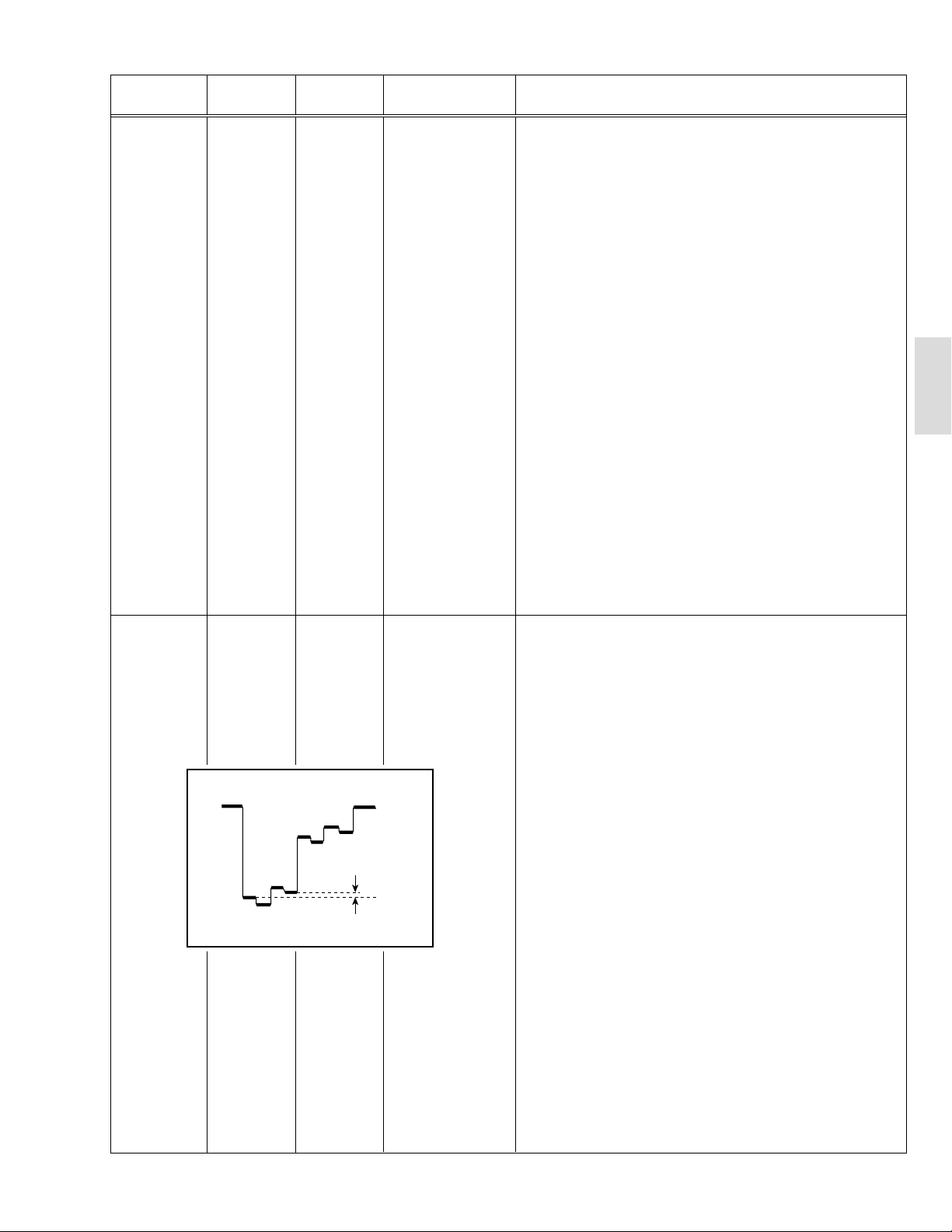
5. COLOUR [Method of adjustment using measuring instrument]
Notes:
• Proceed to the following this adjustment after having completed the
adjustment of SUB CONT.
• Set PICTURE MODE (VSM) to “BRIGHT”.
– PAL COLOUR –
1. Receive a PAL colour bar signal (full field colour bar 75% white).
2. Select 2. VC from the SERVICE MENU.
3. Select 5. COLOUR with the MENU &/^ key.
4. Set the initial setting value of PAL COLOUR with the MENU –/+ key.
5. Connect the oscilloscope between TP-47G and TP-E.
B
R
(A)
(–)
0V
(+)
6.
Adjust PAL COLOUR to set the value (A) in the figure to +14V (V
W-G
– SECAM COLOUR –
7. Receive a SECAM colour bar signal (full field colour bar 75% white).
8. Press the COLOUR SYSTEM button on the remote control unit to
select the SECAM colour system.
9. Set the initial setting value of SECAM COLOUR with the MENU –/+ key.
).
10. Adjust SECAM COLOUR to set the value (A) in the figure to +5V
(VW-G ).
– NTSC 3.58 COLOUR –
11. Receive a NTSC 3.58 colour bar signal (full field colour bar 75% white).
12. Press the COLOUR SYSTEM button on the remote control unit to
select the NTSC 3.58 colour system.
13. Set the initial setting value of NTSC 3.58 COLOUR with the MENU
–/+ key.
14. Adjust NTSC 3.58 COLOUR to set the value (A) in the figure to
+5V (VW-G).
– NTSC 4.43 COLOUR –
When adjustment is done for NTSC 3.58 COLOUR, appropriate
values are automatically set for NTSC 4.43 COLOUR.
No. 51901 5
Page 6
AV-2108TEE
Item
Adjustment
of
SUB TINT-I
Measuring
instrument
Remote
control unit
Test point Adjustment part Description
6. TINT [Method of adjustment without measuring instrument]
Notes:
• Proceed to the following this adjustment after having completed the
adjustment of SUB CONT.
• Set PICTURE MODE (VSM) to “BRIGHT”.
– NTSC 3.58 TINT –
1. Receive a NTSC 3.58 colour bar signal (full field colour bar 75%
white).
2. Press the COLOUR SYSTEM button on the remote control unit to
select the NTSC 3.58 colour system.
3. Select 2. VC from the SERVICE MENU.
4. Select 6. TINT with the MENU &/^ key.
5. Set the initial setting value of NTSC 3.58 with the MENU –/+ key.
6. If you cannot get the best tint with the initial setting value, make fine
adjustment until you get the best tint.
7. Press the DISPLAY key twice to return to the normal screen.
– NTSC 4.43 TINT –
When adjustment is done for NTSC 3.58 TINT, appropriate values are
automatically set for NTSC 4.43 TINT.
Adjustment
of SUB
SUB TINT-II
Signal
generator
Oscilloscope
Remote
control unit
(B)
W
Y
Cy
TP-47G
TP-E (H)
[CRT
SOCKET
PWB]
B
Mg
R
G
6. TINT [Method of adjustment using measuring instrument]
Notes:
• Proceed to the following this adjustment after having completed the
adjustment of SUB CONT.
• Set PICTURE MODE (VSM) to “BRIGHT”.
– NTSC 3.58 TINT –
1. Receive a NTSC 3.58 colour bar signal (full field colour bar 75%
white).
2. Press the COLOUR SYSTEM button on the remote control unit to
select the NTSC 3.58 colour system.
3. Select 2. VC from the SERVICE MENU.
4. Select 6. TINT with the MENU &/^ key.
5. Set the initial setting value of NTSC 3.58 with the MENU –/+ key.
6. Connect the oscilloscope between TP-47G and TP-E.
(–)
0V
(+)
7. Adjust NTSC 3.58 TINT to set the value (B) in the figure to +6V
(VW-Cy).
8. Press the DISPLAY key twice to return to the normal screen.
– NTSC 4.43 TINT –
When adjustment is done for NTSC 3.58 TINT, appropriate values are
automatically set for NTSC 4.43 TINT.
6 No. 51901
Page 7
AV-2108TEE
DEFLECTION CIRCUIT ADJUSTMENT
The setting (adjustment) using the remote control unit is made on the basis of the initial setting values.
The setting values which adjust the screen to the optimum condition can be different from the initial setting values.
Note:
Proceed to the following this adjustment after having completed the adjustments of SUB BRIGHT and SUB CONT.
[SUB MENU 3. DEF] : Do not adjust.
Setting
(Adjustment)
item
Variable range
50Hz 60Hz
4:3
1. VER. SLOPE –31 — +31 +6 –1 —— —
2. VER. HEIGHT –31 — +31 +31 +31 –9 –30 —
3. VER. POSITION –31 — +31 –9+1—— —
4. VER. SCURVE –31 — +31 –21 –2 —— —
5. HOR. POSITION –31 — +31 +5 +6 —— +7
6. HOR. WIDTH –31 — +31 0 0 —— —
7. EW-PIN –31 — +31 0 0 0 0 —
8. EW-TRAPEZ –31 — +31 0 0 —— —
9. UP CORNER –31 — +31 0 0 0 0 —
10. DW CORNER –31 — +31 0 0 0 0 —
11. HOR. PARALL –31 — +31 –11 0 —— —
12. HOR. BOW –31 — +31 0 0 —— —
13. V.ZOOM –31 — +31 –1 –3 +11 +14 —
Initial setting value
COMPRESS(16:9)
50Hz 60Hz
COMPONENT
DVD(50Hz/60Hz)
AV-2108TEE
[fv : 50Hz mode]
Item
Adjustment
of
VER. SLOPE
Adjustment
of
VER.POSITION
Measuring
instrument
Signal
generator
Remote
control unit
Signal
generator
Remote
control unit
Test point Adjustment part Description
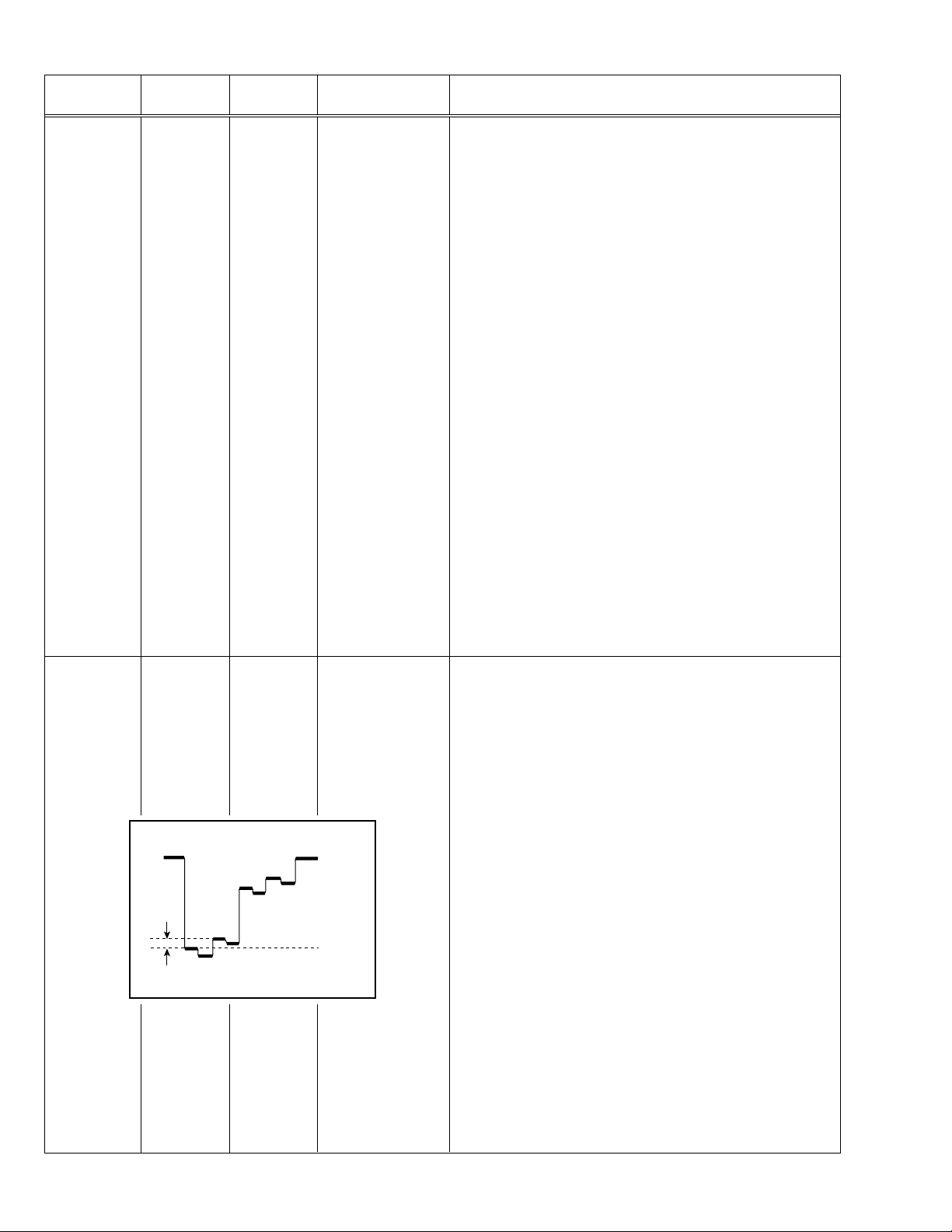
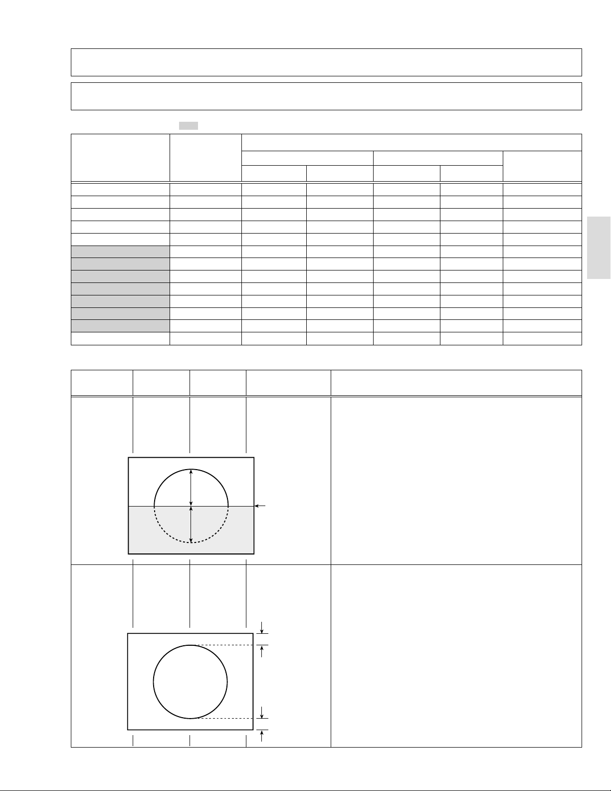
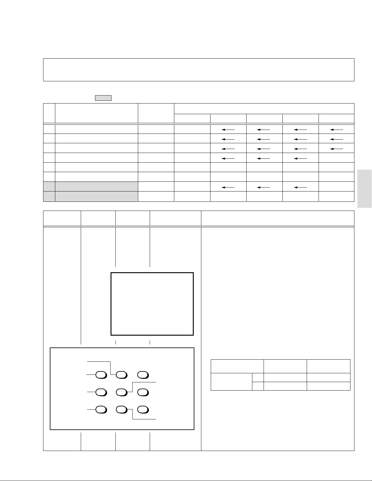
1. VER. SLOPE 1. Receive a PAL circle pattern signal of vertical frequency 50Hz.
2. Select 3. DEF from the SERVICE MENU.
3. Select 1. VER. SLOPE with the MENU &/^ key.
4. Set the initial setting value of 1. VER. SLOPE with the MENU –/+
key.
5. Adjust 1. VER. SLOPE to make “A = B” with the MENU –/+ key.
A
Blanking
line
B
3. VER. POSITION 6. Select 3. VER. POSITION with the MENU &/^ key.
7. Set the initial setting value of 3. VER. POSITION with the MENU
–/+ key.
8. Adjust 3. VER. POSITION to make “A = B” with the MENU –/+ key.
A
(to be continued)
B
No. 51901 7
Page 8
AV-2108TEE
PRESET ADJUSTMENT
Do not adjust 5. PRESET in the SERVICE MENU as it requires no adjustment.
•
[SUB MENU 5. PRESET]
Setting item Variable range Initial setting value
1 CB 0/1 0
2 ACL 0/1 0
3 MUS 0/1 0
4 MAT 0/1 0
5 FCO 0/1 0
6 BPS 0/1 0
7 IFLH 0/1 0
8 VID 0/1 0
9 STM 0/1 0
10 AFCW 0/1 0
11 VSW 0/1 0
12 FFI 0/1 0
13 AGC 00/10/01 10
14 CL 50 – 95 80
15 AKB 0/1 0
16 HBL 0/1 0
17 BKS 0/1 1
18 READ STATUS ——
19 VNR 00 – 63 25
8 No. 51901
Page 9
AV-2508TEE
SPECIFIC SERVICE INSTRUCTIONS [AV-2508TEE/B]
SETTING OF SYSTEM CONSTANT SET
Setting item Setting content
SYSTEM
COMB
TILT
TEXT
SUPER BASS
LANGUAGE
MSP
BILINGUAL
B/B SOUND
TUNER
MULTI TRIPLE
YES NO
YES NO
YES NO
YES NO
E/R/C E/R/A/F
E/F E/A
E/R E/C E/A/F
YES NO
YES NO
YES NO
MU MA
AV-25LS AV-25LS-AU
MULTI
NO
NO
ARABIC
E/R/C
PAN EURO NO
NO
YES
NO
NO
MU
Setting value
AV-25LH AV-25LX-AU AV-2508TEE AV-2508TEE/BAV-25X-A
AV-25LX
E/C E/R/A/F E/R/C E/R
NO
YES NO
RUSSIAN UKRANIAN
COLOUR AUTO
LOCK 1MHz
500KHz
250KHz
156.25KHz
31.25KHz
NOTE : (
***
YES NO
000 024
000 024
000 024
000 024
000 024
) is for Micon (IC1701) Part No. TDA9365N13S0518.
NO
020(040)
020(040)
020(040)
015(030)
015(030)
Table 1
020
020
020
015
015
YES NO
020(040)
020(040)
020(040)
015(030)
015(030)
(040)
(040)
(040)
(030)
(030)
18 No. 51901
Page 10
AV-2508TEE
SERVICE ADJUSTMENTS [AV-2508TEE/B]
VC (VIDEO/CHROMA) CIRCUIT ADJUSTMENT
The setting (adjustment) using the remote control unit is made on the basis of the initial setting values.
The setting values which adjust the screen to the optimum condition can be different from the initial setting values.
Do not change the initial setting values of the setting (adjustment) items not listed in “ADJUSTMENT”.
•
[SUB MENU 2. VC] : Do not adjust.
Setting (Adjustment) item Variable range
Initial setting value
PAL SECAM NTSC3.58 NTSC4.43 COMPONENT
1 CUTOFF(R/G) –7 — +8 0
2 DRIVE(R/G/B) –30 — +31 0
3 BRIGHT(COM./TV/V-1/V-2/V-3) –30 — +31 0/–18/0/0/0
4 CONT –30 — +31 –20 —
5 COLOUR –30 — +31 5 –3 –12 –6 +10
6 TINT (TV/VIDEO) –30 — +31 — — –12/+4 +1/+1 —
7 SHARP (TV/VIDEO) –30 — +31 –16/–2 —/0
8 YDELAY (TV/VIDEO/S) –8 — +7 0/+1/0 +5/+1/+1 0/+1/+1 +5/0/+1 —
Item
Adjustment
of WHITE
Measuring
instrument
Signal
generator
Test point Adjustment part Description
1. CUTOFF (R)
CUTOFF (G)
Note:
• Set PICTURE MODE (VSM) to “BRIGHT”.
BALANCE
(Low light)
Remote
control unit
SCREEN VR
[In HVT]
1. Receive a PAL black and white signal (colour off).
2. Select 2. VC from the SERVICE MENU.
3. Select 1. CUTOFF (R) and (G) with MENU &/^ key, and set each
value to initial setting value with the 4 and 7 keys, or 5 and 8 keys on
V/C
-
/+ : OPERATE
(R)
(G)
1. CUTOFF
50 Hz
MENU 89: SELECT
MENU
PAL
**
**
DISPLAY : EXIT
the remote control unit.
4. Press the 1 key on the remote control unit to produce a single hori-
zontal line.
5. Turn the SCREEN VR fully counterclockwise, then slowly turn it clockwise to where a red, blue or green colour is faintly visible.
6. Use the keys 4 and 7 or 5 and 8 on the remote control unit and
adjust the other 2 colours to where the single horizontal line appears white.
7. Turn the SCREEN VR to where the single horizontal line glows faintly.
8. Press the 2 key to return to 1. CUTOFF screen.
9. Press the DISPLAY key twice to return to the normal screen.
Setting (Adjustment) Variable Initial setting
Item range value
1. CUT OFF
R –7 — +8 0
G –7 — +8 0
H.LINE OFF
H.LINE ON
R. CUTOFF (
REMOTE CONTROL UNIT
12 3
4
8
)
56
G. CUTOFF (8)
AV-2508TEE
R. CUTOFF (
789
)
9
G.CUTOFF (
)
9
No. 51901 19
Page 11
AV-2508TEE
Item
Adjustment
of
SUB
COLOUR-I
Measuring
instrument
Remote
control unit
Test point Adjustment part Description
5. COLOUR
[Method of adjustment without measuring instrument]
Notes:
• Proceed to the following this adjustment after having completed the
adjustment of SUB CONT.
• Set PICTURE MODE (VSM) to “BRIGHT”.
– PAL COLOUR –
1. Receive a PAL broadcast.
2. Select 2. VC from the SERVICE MENU.
3. Select 5. COLOUR with the MENU &/^ key.
4. Set the initial setting value for PAL COLOUR with the MENU –/+ key.
5. If the colour is not best with the initial setting value, make fine ad-
justment until you get the best colour.
6. Press the DISPLAY key twice to return to the normal screen.
– SECAM COLOUR –
7. Receive a SECAM broadcast.
8. Press the COLOUR SYSTEM button on the remote control unit to
select the SECAM colour system.
9. Make fine adjustment of SECAM COLOUR in the same way as for
“PAL COLOUR”.
– NTSC 3.58 COLOUR –
10. Receive a NTSC 3.58MHz broadcast.
11. Press the COLOUR SYSTEM button on the remote control unit to
select the NTSC 3.58 colour system.
12. Make similar fine adjustment of NTSC 3.58 COLOUR in the same
way as for “PAL COLOUR”.
– NTSC 4.43 COLOUR –
When adjustment is done for NTSC 3.58 COLOUR, appropriate
values are automatically set for NTSC 4.43 COLOUR.
Adjustment
of SUB
COLOUR-II
Signal
generator
Oscilloscope
Remote
control unit
Cy
Y
W
TP-47G
TP-E (H)
[CRT
SOCKET
PWB]
Mg
G
5. COLOUR [Method of adjustment using measuring instrument]
Notes:
• Proceed to the following this adjustment after having completed the
adjustment of SUB CONT.
• Set PICTURE MODE (VSM) to “BRIGHT”.
– PAL COLOUR –
1. Receive a PAL colour bar signal (full field colour bar 75% white).
2. Select 2. VC from the SERVICE MENU.
3. Select 5. COLOUR with the MENU &/^ key.
4. Set the initial setting value of PAL COLOUR with the MENU –/+ key.
5. Connect the oscilloscope between TP-47G and TP-E.
B
R
(A)
(–)
0V
(+)
6.
Adjust PAL COLOUR to set the value (A) in the figure to +14V (V
W-G
– SECAM COLOUR –
7. Receive a SECAM colour bar signal (full field colour bar 75% white).
8. Press the COLOUR SYSTEM button on the remote control unit to
select the SECAM colour system.
9. Set the initial setting value of SECAM COLOUR with the MENU –/+ key.
).
10. Adjust SECAM COLOUR to set the value (A) in the figure to –3V
(VW-G).
– NTSC 3.58 COLOUR –
11. Receive a NTSC 3.58 colour bar signal (full field colour bar 75% white).
12. Press the COLOUR SYSTEM button on the remote control unit to
select the NTSC 3.58 colour system.
13. Set the initial setting value of NTSC 3.58 COLOUR with the MENU
–/+ key.
14. Adjust NTSC 3.58 COLOUR to set the value (A) in the figure to
+3V (VW-G).
– NTSC 4.43 COLOUR –
When adjustment is done for NTSC 3.58 COLOUR, appropriate
values are automatically set for NTSC 4.43 COLOUR.
20 No. 51901
Page 12

AV-2508TEE
Item
Adjustment
of
SUB TINT-I
Measuring
instrument
Remote
control unit
Test point Adjustment part Description
6. TINT [Method of adjustment without measuring instrument]
Notes:
• Proceed to the following this adjustment after having completed the
adjustment of SUB CONT.
• Set PICTURE MODE (VSM) to “BRIGHT”.
– NTSC 3.58 TINT –
1. Receive a NTSC 3.58 colour bar signal (full field colour bar 75%
white).
2. Press the COLOUR SYSTEM button on the remote control unit to
select the NTSC 3.58 colour system.
3. Select 2. VC from the SERVICE MENU.
4. Select 6. TINT with the MENU &/^ key.
5. Set the initial setting value of NTSC 3.58 with the MENU –/+ key.
6. If you cannot get the best tint with the initial setting value, make fine
adjustment until you get the best tint.
7. Press the DISPLAY key twice to return to the normal screen.
– NTSC 4.43 TINT –
When adjustment is done for NTSC 3.58 TINT, appropriate values are
automatically set for NTSC 4.43 TINT.
AV-2508TEE
Adjustment
of SUB
SUB TINT-II
Signal
generator
Oscilloscope
Remote
control unit
(B)
Cy
W
Y
TP-47G
TP-E (H)
[CRT
SOCKET
PWB]
B
Mg
R
G
6. TINT [Method of adjustment using measuring instrument]
Notes:
• Proceed to the following this adjustment after having completed the
adjustment of SUB CONT.
• Set PICTURE MODE (VSM) to “BRIGHT”.
– NTSC 3.58 TINT –
1. Receive a NTSC 3.58 colour bar signal (full field colour bar 75%
white).
2. Press the COLOUR SYSTEM button on the remote control unit to
select the NTSC 3.58 colour system.
3. Select 2. VC from the SERVICE MENU.
4. Select 6. TINT with the MENU &/^ key.
5. Set the initial setting value of NTSC 3.58 with the MENU –/+ key.
6. Connect the oscilloscope between TP-47G and TP-E.
(–)
0V
(+)
7.
Adjust NTSC 3.58 TINT to set the value (B) in the figure to +3V (V
8. Press the DISPLAY key twice to return to the normal screen.
– NTSC 4.43 TINT –
When adjustment is done for NTSC 3.58 TINT, appropriate values are
automatically set for NTSC 4.43 TINT.
W-cy
).
No. 51901 21
Page 13

AV-2508TEE
DEFLECTION CIRCUIT ADJUSTMENT
The setting (adjustment) using the remote control unit is made on the basis of the initial setting values.
The setting values which adjust the screen to the optimum condition can be different from the initial setting values.
Note:
Proceed to the following this adjustment after having completed the adjustments of SUB BRIGHT and SUB CONT.
[SUB MENU 3. DEF]
Setting
(Adjustment)
item
Variable range
50Hz 60Hz
4:3
1. VER. SLOPE –31 — +31 0 0 —— —
2. VER. HEIGHT –31 — +31 +31 +31 0 0 —
3. VER. POSITION –31 — +31 0 0 —— —
4. VER. SCURVE –31 — +31 –21 –2 —— —
5. HOR. POSITION –31 — +31 0 0 —— +7
6. HOR. WIDTH –31 — +31 0 0 —— —
7. EW-PIN –31 — +31 0 0 0 0 —
8. EW-TRAPEZ –31 — +31 0 0 —— —
9. UP CORNER –31 — +31 0 0 0 0 —
10. DW CORNER –31 — +31 0 0 0 0 —
11. HOR. PARALL –31 — +31 0 0 —— —
12. HOR. BOW –31 — +31 0 0 —— —
13. V.ZOOM –31 — +31 0 0 0 0 —
Initial setting value
COMPRESS(16:9)
50Hz 60Hz
COMPONENT
DVD(50Hz/60Hz)
[fv : 50Hz mode]
Item
Adjustment
of
VER. SLOPE
Adjustment
of
VER.POSITION
Measuring
instrument
Signal
generator
Remote
control unit
Signal
generator
Remote
control unit
Test point Adjustment part Description
1. VER. SLOPE 1. Receive a PAL circle pattern signal of vertical frequency 50Hz.
2. Select 3. DEF from the SERVICE MENU.
3. Select 1. VER. SLOPE with the MENU &/^ key.
4. Set the initial setting value of 1. VER. SLOPE with the MENU –/+
key.
5. Adjust 1. VER. SLOPE to make “A = B” with the MENU –/+ key.
A
Blanking
line
B
3. VER. POSITION 6. Select 3. VER. POSITION with the MENU &/^ key.
7. Set the initial setting value of 3. VER. POSITION with the MENU
–/+ key.
8. Adjust 3. VER. POSITION to make “A = B” with the MENU –/+ key.
A
(to be continued)
B
22 No. 51901
Page 14

AV-2508TEE
PRESET ADJUSTMENT
Do not adjust 5. PRESET in the SERVICE MENU as it requires no adjustment.
•
[SUB MENU 5. PRESET]
Setting item Variable range Initial setting value
1 CB 0/1 0
2 ACL 0/1 0
3 MUS 0/1 0
4 MAT 0/1 0
5 FCO 0/1 0
6 BPS 0/1 0
7 IFLH 0/1 0
8 VID 0/1 0
9 STM 0/1 0
10 AFCW 0/1 0
11 VSW 0/1 0
12 FFI 0/1 0
13 AGC 00/10/01 10
14 CL 50 – 95 83
15 AKB 0/1 0
16 HBL 0/1 0
17 BKS 0/1 1
18 READ STATUS ——
19 VNR 00 – 63 25
AV-2508TEE
No. 51901 23
Page 15

AV-2908TEE
SPECIFIC SERVICE INSTRUCTIONS [AV-2908TEE/B]
SETTING OF SYSTEM CONSTANT SET
Setting item Setting content
SYSTEM
COMB
TILT
TEXT
SUPER BASS
LANGUAGE
MSP
BILINGUAL
B/B SOUND
TUNER
MULTI TRIPLE
YES NO
YES NO
YES NO
YES NO
E/R/C E/R/A/F
E/F E/A
E/R E/C E/A/F
YES NO
YES NO
YES NO
MU MA
AV-29LS AV-29LS-AU
MULTI
YES
YES
ARABIC
E/R/C
PAN EURO NO
NO
YES
NO
NO
MU
Setting value
AV-29LH AV-29LX-AU AV-2908TEE AV-2908TEE/BAV-29X-A
AV-29LX
E/C E/R/A/F E/R/C E/R
NO
YES NO
RUSSIAN UKRANIAN
COLOUR AUTO
LOCK 1MHz
500KHz
250KHz
156.25KHz
31.25KHz
NOTE : (
) is for Micon (IC1701) Part No. TDA9365N13S0518.
***
YES NO
000 024
000 024
000 024
000 024
000 024
NO
020(040)
020(040)
020(040)
015(030)
015(030)
Table 1
020
020
020
015
015
YES NO
020(040)
020(040)
020(040)
015(030)
015(030)
(040)
(040)
(040)
(030)
(030)
30 No. 51901
Page 16

AV-2908TEE
SERVICE ADJUSTMENTS [AV-2908TEE/B]
B1 POWER SUPPLY
Item
Measuring
instrument
Test point Adjustment part Description
Check of
B1 POWER
SUPPLY
Signal
Generator
DC Voltmeter
FOCUS ADJUSTMENT
Item
Adjustment
of FOCUS
Measuring
instrument
Signal
generator
B1 (pin 1)
GND (pin 5)
[CN00S
connector]
Test point Adjustment part Description
FOCUS VR1,2
[In HVT]
1. Receive a black and white signal.
2. Connect a DC voltmeter between B1 and GND
(between pins 1 and 5 of the connector CN00S).
3. Make sure that the voltage is DC134.5 ± 2V.
Notes:
• Proceed to the following this adjustment after having completed the
adjustments of B1 POWER SUPPLY, SUB BRIGHT and SUB CONT.
• Set PICTURE MODE (VSM) to “BRIGHT”.
• The final adjustment of CONVERGENCE must be done after the
FOCUS adjustment. (CONVERGENCE is changed by FOCUS adjustment.)
When makes difference by FOCUS adjustment, should be reconfirming
PURITY adjustment.
1. Receive a cross-hatch signal.
2. While looking at the screen centre, adjust the FOCUS VR2 (F2) so
that the horizontal lines will be clear and in fine detail.
3. Adjust the FOCUS VR1 (F1) so that the vertical lines will be clear
and in fine detail.
4. Make sure that the picture is in focus even when the screen gets
darkened.
AV-2908TEE
IF CIRCUIT ADJUSTMENT
Item
Adjustment
of VCO (CW)
Adjustment
of DELAY
POINT
Setting
(Adjustment time)
DELAY POINT
(AGC TAKE-OVER)
Measuring
instrument
Remote
control unit
VCO (CW)
TOO HIGH
ABOVE REFERENCE
BELOW REFERENCE
TOO LOW
Remote
control unit
Test point Adjustment part Description
. MHz
DISPLAY : EXIT
NTSC 3.58 22
OTHERS 15
VCO (CW)
fv
YELLOW
DELAY POINT
(AGC TAKE-OVER)
Initial setting value
Note:
• Under normal conditions, no adjustment is required.
1. Select 1. IF from the SERVICE MENU.
2. Select 1. VCO by pressing the 1 key on the remote control unit.
3. Receive a broadcast signal.
4. Check the characters colour of the BELOW REFERENCE displayed
to yellow.
5. Press the DISPLAY key three times to return to normal screen.
1. Receive a black and white broadcast signal (colour off).
2. Select 1. IF from the SERVICE MENU.
3. Select 2. DELAY POINT by pressing the 2 key on the remote con-
trol unit.
4. Adjust the MENU –/+ key in order to eliminate any noise or beat
from the image. Any increase above the initial value produces noise
and any decrease below it produces beat.
5. Press the DISPLAY key three times to return to the normal screen.
6. Turn to other channels and make sure that there are no irregularities.
No. 51901 31
Page 17

AV-2908TEE
VC (VIDEO/CHROMA) CIRCUIT ADJUSTMENT
The setting (adjustment) using the remote control unit is made on the basis of the initial setting values.
The setting values which adjust the screen to the optimum condition can be different from the initial setting values.
Do not change the initial setting values of the setting (adjustment) items not listed in “ADJUSTMENT”.
•
[SUB MENU 2. VC] : Do not adjust.
Setting (Adjustment) item Variable range
Initial setting value
PAL SECAM NTSC3.58 NTSC4.43 COMPONENT
1 CUTOFF(R/G) –7 — +8 0
2 DRIVE(R/G/B) –32 — +31 0
3 BRIGHT(COM./TV/V-1/V-2/V-3) –32 — +31 –1/–16/0/0/0
4 CONT –32 — +31 0 —
5 COLOUR –32 — +31 –5 –3 –12 +1 +10
6 TINT (TV/VIDEO) –32 — +31 ——–15/+6 +1/+1 —
7 SHARP (TV/VIDEO) –32 — +31 –24/–10 —/0
8 YDELAY (TV/VIDEO/S) –8 — +7 0/+1/0 +5/+1/+1 0/+1/+1 +5/0/+1 —
Item
Adjustment
of WHITE
Measuring
instrument
Signal
generator
Test point Adjustment part Description
1. CUTOFF (R)
CUTOFF (G)
Note:
• Set PICTURE MODE (VSM) to “BRIGHT”.
BALANCE
(Low light)
Remote
control unit
SCREEN VR
[In HVT]
1. Receive a PAL black and white signal (colour off).
2. Select 2. VC from the SERVICE MENU.
3. Select 1. CUTOFF (R) and (G) with MENU &/^ key, and set each
value to initial setting value with the 4 and 7 keys, or 5 and 8 keys on
V/C
1. CUTOFF
50 Hz
MENU 89: SELECT
MENU
(R)
(G)
-
/+ : OPERATE
PAL
**
**
DISPLAY : EXIT
the remote control unit.
4. Press the 1 key on the remote control unit to produce a single hori-
zontal line.
5. Turn the SCREEN VR fully counterclockwise, then slowly turn it clockwise to where a red, blue or green colour is faintly visible.
6. Use the keys 4 and 7 or 5 and 8 on the remote control unit and
adjust the other 2 colours to where the single horizontal line appears white.
7. Turn the SCREEN VR to where the single horizontal line glows faintly.
8. Press the 2 key to return to 1. CUTOFF screen.
9. Press the DISPLAY key twice to return to the normal screen.
Setting (Adjustment) Variable Initial setting
Item range value
1. CUT OFF
R –7 — +8 0
G –7 — +8 0
H.LINE OFF
H.LINE ON
R. CUTOFF (
REMOTE CONTROL UNIT
12 3
4
8
)
56
G. CUTOFF (8)
789
R. CUTOFF (
)
9
G.CUTOFF (
)
9
32 No. 51901
Page 18

AV-2908TEE
DEFLECTION CIRCUIT ADJUSTMENT
The setting (adjustment) using the remote control unit is made on the basis of the initial setting values.
The setting values which adjust the screen to the optimum condition can be different from the initial setting values.
Note:
Proceed to the following this adjustment after having completed the adjustments of SUB BRIGHT and SUB CONT.
[SUB MENU 3. DEF]
Setting
(Adjustment)
item
Variable range
50Hz 60Hz
4:3
1. VER. SLOPE –31 — +31 +3 0 —— —
2. VER. HEIGHT –31 — +31 +31 0 –29 –24 —
3. VER. POSITION –31 — +31 +2 –1 —— —
4. VER. SCURVE –31 — +31 –21 0 —— —
5. HOR. POSITION –31 — +31 –4+7—— +7
6. HOR. WIDTH –31 — +31 +11 –1 —— —
7. EW-PIN –31 — +31 –11 –1 –13 –12 —
8. EW-TRAPEZ –31 — +31 0 0 —— —
9. UP CORNER –31 — +31 –25 0 0 0 —
10. DW CORNER –31 — +31 –25 0 0 0 —
11. HOR. PARALL –31 — +31 0 0 —— —
12. HOR. BOW –31 — +31 0 0 —— —
13. V.ZOOM –31 — +31 –1 –1 +14 +6 —
Initial setting value
COMPRESS(16:9)
50Hz 60Hz
COMPONENT
DVD(50Hz/60Hz)
[fv : 50Hz mode]
Item
Adjustment
of
VER. SLOPE
Adjustment
of
VER.POSITION
Measuring
instrument
Signal
generator
Remote
control unit
Signal
generator
Remote
control unit
Test point Adjustment part Description
AV-2908TEE
1. VER. SLOPE 1. Receive a PAL circle pattern signal of vertical frequency 50Hz.
2. Select 3. DEF from the SERVICE MENU.
3. Select 1. VER. SLOPE with the MENU &/^ key.
4. Set the initial setting value of 1. VER. SLOPE with the MENU –/+
key.
5. Adjust 1. VER. SLOPE to make “A = B” with the MENU –/+ key.
A
Blanking
line
B
3. VER. POSITION 6. Select 3. VER. POSITION with the MENU &/^ key.
7. Set the initial setting value of 3. VER. POSITION with the MENU
–/+ key.
8. Adjust 3. VER. POSITION to make “A = B” with the MENU –/+ key.
A
(to be continued)
B
No. 51901 33
Page 19

AV-2908TEE
[fv : 60Hz mode]
Item
Measuring
instrument
Test point Adjustment part Description
Adjustment
of
VER. SLOPE
Adjustment
of
VER.POSITION
Signal
generator
Remote
control unit
Signal
generator
Remote
control unit
1. VER. SLOPE 1. Receive a NTSC circle pattern signal of vertical frequency 60Hz.
2. Select 3. DEF from the SERVICE MENU.
3. Select 1. VER. SLOPE with the MENU &/^ key.
4. Set the initial setting value of 1. VER. SLOPE with the MENU –/+
key.
5. Adjust 1. VER. SLOPE to make “A = B” with the MENU –/+ key.
A
Blanking
line
B
3. VER. POSITION 6. Select 3. VER. POSITION with the MENU &/^ key.
7. Set the initial setting value of 3. VER. POSITION with the MENU
–/+ key.
8. Adjust 3. VER. POSITION to make “A = B” with the MENU –/+ key.
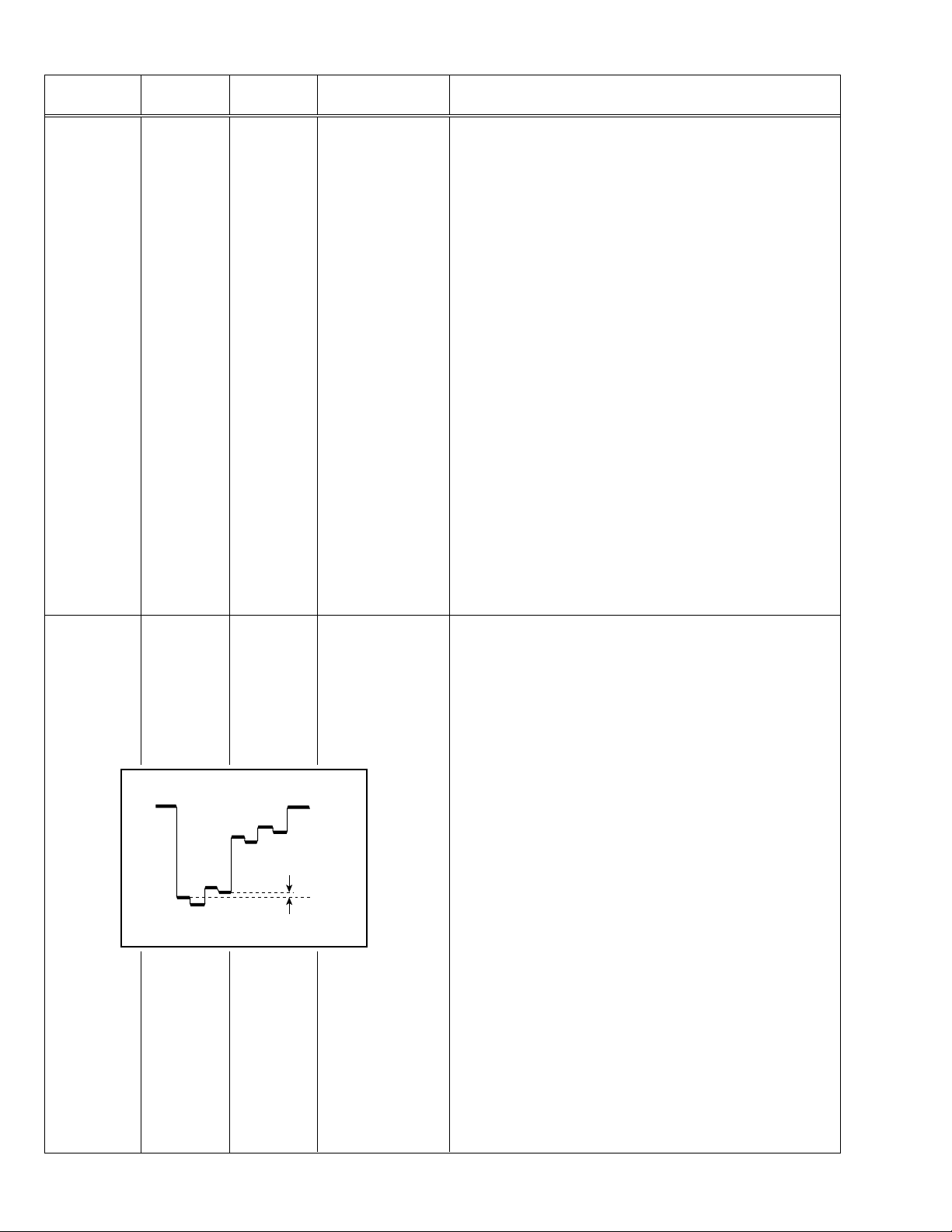
Adjustment
of
V. ZOOM
Screen
size
91%
Signal
generator
Remote
control unit
Screen size
A
B
2. VER. HEIGHT
13. V. ZOOM
Picture
size
100%
9. Receive a NTSC cross-hatch signal.
10. Select 2. VER. HEIGHT with the MENU &/^ key.
11. Set the initial setting value of 2. VER. HEIGHT with the MENU –/+
key.
12. Select 13. V. ZOOM with the MENU &/^ key.
13. Set the initial setting value of 13. V. ZOOM with the MENU –/+ key.
14. Adjust 13. V. ZOOM and make the vertical screen size 91% of the
picture size with the MENU –/+ key.
(to be continued)
Picture size 100%
34 No. 51901
Page 20

AV-2908TEE
Item
Adjustment
of
HOR. POSITION
Adjustment
of
HOR. WIDTH
Measuring
instrument
Signal
Test point Adjustment part Description
5. HOR. POSITION 15. Receive a NTSC circle pattern signal.
generator
Remote
control unit
CD
Signal
6. HOR. WIDTH 19. Receive a NTSC cross-hatch signal.
generator
Remote
control unit
Screen size 91%
16. Select 5. HOR. POSITION with the MENU &/^ key.
17. Set the initial setting value of 5. HOR. POSITION with the MENU
–/+ key.
18. Adjust 5. HOR. POSITION to make “C=D” with the MENU –/+ key.
20. Select 6. HOR. WIDTH with the MENU &/^ key.
21. Set the initial setting value of 6. HOR. WIDTH with the MENU –/+
key.
22. Adjust 6. HOR. WIDTH and make the horizontal screen size 91%
of the picture size with the MENU –/+ key.
Screen
Adjustment
of
EW-PIN
size
91%
Signal
generator
Remote
control unit
AV-2908TEE
Picture
size
100%
Picture size 100%
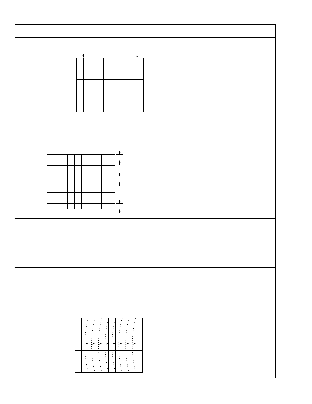
7. EW-PIN 23. Select 7. EW-PIN with the MENU &/^ key.
24. Set the initial setting value of 7. EW-PIN with the MENU –/+ key.
25. Adjust 7. EW-PIN so that the first vertical lines at the left and right
edges on the screen are straight.
Straight
(to be continued)
No. 51901 35
Page 21
AV-2908TEE
Item
Adjustment
of
EW-TRAPEZ
Adjustment
of
VER. SCURVE
Measuring
instrument
Signal
generator
Remote
control unit
Signal
generator
Remote
control unit
Test point Adjustment part Description
8. EW-TRAPEZ 26. Select 8. EW-TRAPEZ with the MENU &/^ key.
27. Set the initial setting value of 8. EW-TRAPEZ with the MENU –/+
Parallel
key.
28. Adjust 8. EW-TRAPEZ so that the vertical lines at the left and right
edges on the screen are in parallel.
4. VER. SCURVE 29. Select 4. VER. SCURVE with the MENU &/^ key.
30.Set the initial setting value of 4. VER. SCURVE with the MENU –/+
key.
31. Adjust 4. VER. SCURVE so that the spaces of each line on TOP,
CENTRE and BOTTOM become uniform.
TOP
Adjustment
of
UP CORNER
and
DW CORNER
Adjustment
of
HOR. PARALL
Adjustment
of
HOR. BOW
Signal
generator
Remote
control unit
Signal
generator
Remote
control unit
Signal
generator
Remote
control unit
CENTRE
BOTTOM
9. UP CORNER
10. DW CORNER
32. Select 9. UP CORNER with the MENU &/^ key.
33. Set the initial setting value of 9. UP CORNER with the MENU –/+
key.
34. Sekect 10. DW CORNER with the MENU &/^ key.
35. Set the initial setting value of 10. DW CORNER with the MENU –/+
key.
36. Adjust 9. UP CORNER and 10. DW CORNER so that the vertical
lines at the four corners on the screen are straight.
11. HOR. PARALL 37. Select 11. HOR. PARALL with the MENU &/^ key.
38. Set the initial setting value of 11. HOR. PARALL with the MENU
–/+ key.
39. Adjust 11. HOR. PARALL to optimize the parallelogram distortion.
12. HOR. BOW 40. Select 12. HOR. BOW with the MENU &/^ key.
Straight
41. Set the initial setting value of Select 12. HOR. BOW with the MENU
–/+ key.
42. Adjust 12. HOR. BOW to optimize the horizontal arc distortion.
43. Press the DISPLAY key twice to return to the normal screen.
36 No. 51901
Page 22

AV-2908TEE
PRESET ADJUSTMENT
Do not adjust 5. PRESET in the SERVICE MENU as it requires no adjustment.
•
[SUB MENU 5. PRESET]
Setting item Variable range Initial setting value
1 CB 0/1 0
2 ACL 0/1 0
3 MUS 0/1 0
4 MAT 0/1 0
5 FCO 0/1 0
6 BPS 0/1 0
7 IFLH 0/1 0
8 VID 0/1 0
9 STM 0/1 0
10 AFCW 0/1 0
11 DIDEOSW 0/1 0
12 FFI 0/1 0
13 AGC 00/10/01 10
14 CL 50 – 95 77
15 AKB 0/1 0
16 HBL 0/1 0
17 BKS 0/1 1
18 READ STATUS ——
19 VNR 00 – 63 25
AV-2908TEE
No. 51901 37
Page 23

SPECIFIC SERVICE INSTRUCTIONS [AV-3408TEE/B]
SETTING OF SYSTEM CONSTANT SET
AV-3408TEE
Setting item Setting content
SYSTEM MULTI
COMB
TILT
TEXT
SUPER BASS
LANGUAGE
MSP
BILINGUAL
B/B SOUND
TUNER
MULTI TRIPLE
PA L
YES NO
YES NO
YES NO
YES NO
E/R/C E/R/A/F
E/F E/A
E/R E/C E/A/F
YES NO
YES NO
YES NO
MU MA
AV-34LS AV-34LS-AU AV-34LXAV-34LH AV-3408TEE AV-3408TEE/BAV-34X-A
YES
YES
ARABIC
NO
E/R/C
YES
NO
NO
MU
PAN EURO NO
E/C E/R/A/F E/R
Setting value
NO
YES
RUSSIAN UKRANIAN
NO
COLOUR AUTO
LOCK 1MHz
500KHz
250KHz
156.25KHz
31.25KHz
NOTE : (
***
YES NO
000 024
000 024
000 024
000 024
000 024
) is for Micon (IC1701) Part No. TDA9365N13S0518.
NO
020(040)
020(040)
020(040)
015(030)
015(030)
Table 1
020
020
020
015
015
YES
NO
020(040)
020(040)
020(040)
015(030)
015(030)
(040)
(040)
(040)
(030)
(030)
AV-3408TEE
No. 51901 49
Page 24

AV-3408TEE
SERVICE ADJUSTMENTS [AV-3408TEE/B]
ADJUSTMENTS
B1 POWER SUPPLY
Item
Measuring
instrument
Test point Adjustment part Description
Check of
B1 POWER
SUPPLY
Signal
Generator
DC Voltmeter
FOCUS ADJUSTMENT
Item
Adjustment
of FOCUS
Measuring
instrument
Signal
generator
B1 (pin 1)
GND (pin 5)
[CN00S
connector]
Test point Adjustment part Description
FOCUS VR1,2
[In HVT]
1. Receive a black and white signal.
2. Connect a DC voltmeter between B1 and GND
(between pins 1 and 5 of the connector CN00S).
3. Make sure that the voltage is DC134.5 ± 2V.
Notes:
• Proceed to the following this adjustment after having completed the
adjustments of B1 POWER SUPPLY, SUB BRIGHT and SUB CONT.
• Set PICTURE MODE (VSM) to “BRIGHT”.
• The final adjustment of CONVERGENCE must be done after the
FOCUS adjustment. (CONVERGENCE is changed by FOCUS adjustment.)
When makes difference by FOCUS adjustment, should be reconfirming
PURITY adjustment.
1. Receive a cross-hatch signal.
2. While looking at the screen centre, adjust the FOCUS VR2 (F2) so
that the horizontal lines will be clear and in fine detail.
3. Adjust the FOCUS VR1 (F1) so that the vertical lines will be clear
and in fine detail.
4. Make sure that the picture is in focus even when the screen gets
darkened.
IF CIRCUIT ADJUSTMENT
Item
Adjustment
of VCO (CW)
Adjustment
of DELAY
POINT
Setting
(Adjustment time)
DELAY POINT
(AGC TAKE-OVER)
Measuring
instrument
Remote
control unit
VCO (CW)
TOO HIGH
ABOVE REFERENCE
BELOW REFERENCE
TOO LOW
Remote
control unit
Test point Adjustment part Description
. MHz
DISPLAY : EXIT
NTSC 3.58 22
OTHERS 15
VCO (CW)
fv
YELLOW
DELAY POINT
(AGC TAKE-OVER)
Initial setting value
Note:
• Under normal conditions, no adjustment is required.
1. Select 1. IF from the SERVICE MENU.
2. Select 1. VCO by pressing the 1 key on the remote control unit.
3. Receive a broadcast signal.
4. Check the characters colour of the BELOW REFERENCE displayed
to yellow.
5. Press the DISPLAY key three times to return to normal screen.
1. Receive a black and white broadcast signal (colour off).
2. Select 1. IF from the SERVICE MENU.
3. Select 2. DELAY POINT by pressing the 2 key on the remote con-
trol unit.
4. Adjust the MENU –/+ key in order to eliminate any noise or beat
from the image. Any increase above the initial value produces noise
and any decrease below it produces beat.
5. Press the DISPLAY key three times to return to the normal screen.
6. Turn to other channels and make sure that there are no irregulari-
ties.
50 No. 51901
Page 25

VC (VIDEO/CHROMA) CIRCUIT ADJUSTMENT
The setting (adjustment) using the remote control unit is made on the basis of the initial setting values.
The setting values which adjust the screen to the optimum condition can be different from the initial setting values.
Do not change the initial setting values of the setting (adjustment) items not listed in “ADJUSTMENT”.
•
[SUB MENU 2. VC] : Do not adjust.
AV-3408TEE
Setting (Adjustment) item Variable range
Initial setting value
PAL SECAM NTSC3.58 NTSC4.43 COMPONENT
1 CUTOFF(R/G) –7 — +8 0 0/+3
2 DRIVE(R/G/B) –32 — +31 0
3 BRIGHT(COM./TV/V-1/V-2/V-3) –32 — +31 –1/–16/0/0/0
4 CONT –32 — +31 0 —
5 COLOUR –32 — +31 –5 –3 –12 +1 +10
6 TINT (TV/VIDEO) –32 — +31 ——–15/+6 +1/+1 —
7 SHARP (TV/VIDEO) –32 — +31 –24/–10 —/0
8 YDELAY (TV/VIDEO/S) –8 — +7 0/+1/0 +5/+1/+1 0/+1/+1 +5/0/+1 —
Item
Adjustment
of WHITE
Measuring
instrument
Signal
generator
Test point Adjustment part Description
1. CUTOFF (R)
CUTOFF (G)
Note:
• Set PICTURE MODE (VSM) to “BRIGHT”.
BALANCE
(Low light)
Remote
control unit
SCREEN VR
[In HVT]
1. Receive a PAL black and white signal (colour off).
2. Select 2. VC from the SERVICE MENU.
3. Select 1. CUTOFF (R) and (G) with MENU &/^ key, and set each
value to initial setting value with the 4 and 7 keys, or 5 and 8 keys on
V/C
1. CUTOFF
50 Hz
MENU 89: SELECT
MENU
(R)
(G)
-
/+ : OPERATE
PAL
**
**
DISPLAY : EXIT
the remote control unit.
4. Press the 1 key on the remote control unit to produce a single hori-
zontal line.
5. Turn the SCREEN VR fully counterclockwise, then slowly turn it clockwise to where a red, blue or green colour is faintly visible.
6. Use the keys 4 and 7 or 5 and 8 on the remote control unit and
adjust the other 2 colours to where the single horizontal line appears white.
7. Turn the SCREEN VR to where the single horizontal line glows faintly.
8. Press the 2 key to return to 1. CUTOFF screen.
9. Press the DISPLAY key twice to return to the normal screen.
Setting (Adjustment) Variable Initial setting
Item range value
1. CUT OFF
R –7 — +8 0
G –7 — +8 0
H.LINE OFF
H.LINE ON
R. CUTOFF (
REMOTE CONTROL UNIT
12 3
4
8
)
56
G. CUTOFF (8)
AV-3408TEE
R. CUTOFF (
789
)
9
G.CUTOFF (
)
9
No. 51901 51
Page 26

AV-3408TEE
PRESET ADJUSTMENT
Do not adjust 5. PRESET in the SERVICE MENU as it requires no adjustment.
•
[SUB MENU 5. PRESET]
Setting item Variable range Initial setting value
1 CB 0/1 0
2 ACL 0/1 0
3 MUS 0/1 0
4 MAT 0/1 0
5 FCO 0/1 0
6 BPS 0/1 0
7 IFLH 0/1 0
8 VID 0/1 0
9 STM 0/1 0
10 AFCW 0/1 0
11 VSW 0/1 0
12 FFI 0/1 0
13 AGC 00/10/01 10
14 CL 50 – 95 80
15 AKB 0/1 0
16 HBL 0/1 0
17 BKS 0/1 1
18 READ STATUS ——
19 VNR 00 – 63 25
52 No. 51901
Page 27

PATTERN DIAGRAMS [AV-3408TEE/B]
CRT SOCKET PWB PATTERN (CKF1476-CH2-1)
Pattern diagram is the same as for AV-2908TEE/B. Refer to page 38.
FRONT CONTROL PWB PATTERN (CKF1477-CH2-1)
Pattern diagram is the same as for AV-2908TEE/B. Refer to page 39.
AV-3408TEE
AV-3408TEE
No. 51901 53
Page 28

VICTOR COMPANY OF JAPAN, LIMITED
HOME AV NETWORK BUSINESS UNIT 12, 3-chome, Moriya-cho, kanagawa-ku, Yokohama, kanagawa-prefecture, 221-8528, Japan
AV2108TEEB-H #4
AV2508TEEB-H #4
AV2908TEEB-H #4
AV3408TEEB-H #4
Printed in Japan
VP0109
SW
Page 29

AV-21L31/ME
AV-21L31
AV-25L31
AV-25L31/ME
q
NOTE ON USING CIRCUIT DIAGRAMS
STANDARD CIRCUIT DIAGRAM
1. SAFETY
The components identified by the symbol and shading are
critical for safety. For continued safety replace safety critical
components only with manufactures recommended parts.
2. SPECIFIED VOLTAGE AND WAVEFORM VALUES
The voltage and waveform values have been measured under the
following conditions.
(1) Input signal : Color bar signal
(2)
Setting positions of each knob/button and variable resistor
: Original setting position when
shipped
(3) Internal resistance of tester : DC 20kØ/V
(4) Oscilloscope sweeping time : H ⇒ 20µS/div
:V ⇒ 5mS/div
: Others ⇒ Sweeping time is
specified.
(5) Voltage values : All DC voltage values
9Since the voltage values of signal circuit vary to some extent ac-
cording to adjustments, use them as reference values.
3. INDICATION OF PARTS SYMBOL [EXAMPLE]
• In the PW board : R1209
→
R209
Type
•
No indication : Ceramic capacitor
MY : Mylar capacitor
MM : Metalized mylar capacitor
PP : Polypropylene capacitor
MPP : Metalized polypropylene capacitor
MF : Metalized film capacitor
TF : Thin film capacitor
BP : Bipolar electrolytic capacitor
TAN : Tantalum capacitor
(3) Coils
No unit : [µH]
Others : As specified
(4) Power Supply
:B1
: B2(12V)
:9V
:5V
9Respective voltage values are indicated
(5) Test point
: Test point
: Only test point display
4. INDICATIONS ON THE CIRCUIT DIAGRAM
(1) Resistors
Resistance value
•
No unit : [Ø]
k:[kØ]
M:[MØ]
Rated allowable power
•
No indication : 1/16 [W]
Others : As specified
Type
•
No indication : Carbon resistor
OMR : Oxide metal film resistor
MFR : Metal film resistor
MPR : Metal plate resistor
UNFR : Non-Flammable resistor
FR : Fusible resistor
9Composition resistor 1/2 [W] is specified as 1/2S or Comp.
(2) Capacitors
Capacitance value
•
1 or higher : [pF]
less than 1 : [µF]
Withstand voltage
•
No indication : DC50[V]
AC indicated : AC withstand voltage [V]
Others : DC withstand voltage [V]
9 Electrolytic Capacitors
47/50[Example] : Capacitance value [µF]/withstand voltage[V]
(6) Connecting method
: Connector
: Wrapping or soldering
: Receptacle
(7) Ground symbol
: LIVE side ground
: ISOLATED(NEUTRAL) side ground
: EARTH ground
: DIGITAL ground
5. NOTE FOR REPAIRING SERVICE
This model’s power circuit is partly different in the GND. The difference
of the GND is shown by the LIVE : ( ) side GND and the
ISOLATED(NEUTRAL) : ( ) side GND. Therefore, care must be taken
for the following points.
(1) Do not touch the LIVE side GND or the LIVE side GND and the
ISOLATED(NEUTRAL) side GND simultaneously. If the above caution is not respected, an electric shock may be caused. Therefore,
make sure that the power cord is surely removed from the receptacle when, for example, the chassis is pulled out.
(2) Do not short between the LIVE side GND and ISOLATED(NEUTRAL)
side GND or never measure the LIVE side GND and
ISOLATED(NEUTRAL) side GND at the same time with a measuring apparatus ( oscilloscope, etc.). If the above precaution is not
respected , a fuse or any parts will be broken.
Since the circuit diagram is a standard one, the circuit and cir-
•
cuit constants may be subject to change for improvement without any notice.
Mar. 2002 No. 51908
Page 30

AV-21L31
AV-25L31
CONTENTS
SEMICONDUCTOR SHAPES ................................................................................................................................. 2-2
BLOCK DIAGRAM.......................................................................................................................................................... 2-3
CIRCUIT DIAGRAMS
MAIN PWB CIRCUIT DIAGRAM (1/3) .............................................................................................................................2-5
MAIN PWB CIRCUIT DIAGRAMS (2/3, 3/3) ...................................................................................................................2-7
PATTERN DIAGRAMS
MAIN PWB PATTERN ......................................................................................................................................................... 2-9
MAIN PWB (CRT SOCKET) PATTERN ......................................................................................................................... 2-11
CHANNEL CHART ....................................................................................................................................................... 2-12
SEMICONDUCTOR SHAPES
TRANSISTOR
TOP VIEWBOTTOM VIEW FRONT VIEW
CHIP TR
E
C
B
ECB
EC
B
(G)(D)(S)
ECB
ECB
C
B
E
IC
CHIP IC
TOP VIEWBOTTOM VIEW FRONT VIEW
OUT
E
IN
IN E OUT
N
N
N
1
N
1N
TOP VIEW
1
N
1N
1N
2-2 No.51908
Page 31

BLOCK DIAGRAM
AV-21L31 AV-21L31
AV-25L31 AV-25L31
J801
VIDEO-1
INPUT
J802,J803
COMPONENT
(VIDEO-2)
INPUT
J804
OUTPUT
J771-J773
FRONT IN
(VIDEO-3)
TU001
TUNER
VIDEO
AUDIO L/MONO
AUDIO R
V/Y
B
C
C
R
AUDIO L/MONO
AUDIO R
VIDEO OUT
AUDIO L
AUDIO R
VIDEO
AUDIO L/MONO
AUDIO R
SCL
SDA
IF
37
36
35
43
44
42
19
MAIN PWB
28
SF101
FILTER
SF102
FILTER
29,30
SCL
SDA
7
V1-V
8
V1-L
10
V1-R
3
V2-Y
1
Y2-V
2
V2-L
4
V2-R
Vout2
Lout2
Rout2
V3-V
V3-L
V3-R
Yin1
Cout1
Yout1
IC801
VIDEO SW
MTV-V
MTV-R
MTV-L
Rout1
Vout1
Lout1
25
27
C
C
13
15
14
26
24
23
Q111 Q109
BUF
IC702
EEPROM
B
R
5,6
CF106
29
23
24
2,3
62,63
43
42
47
48
46
TRAP
SIF IN1
SIF IN2
IF IN1
IF IN2
IC701
V/C DEF.
PROCESSOR
SCL,SDA
SCL1
SDA1
CIN
CVBS/YIN
Y
U
V
7
ROUT
GOUT
BOUT
QSS OUT
VDRB(-)
VDRA(+)
HOUT
IF VOUT
10, 54
BUF
51
52
53
35
21,22
33
38
R
G
B
SCL
BUF
Q150
SDA
2
IC601
MULTI SOUND
PROCESSOR
40 41
26,27
30,31
L, R
L_VOL, R_VOL
IC665
FILTER
5
2
IC650
AUDIO AMP
7
12
MAIN (CRT SOCKET)
IC351
VIDEO AMP
J770
HEADPHONE
JACK
SP
SP
R
V01
L
AC IN
VOL+
VOL- CH+ CH- MENU
REMOCON
RECEIVER
S901
POWER SW
POWER
LED
F901
No.51908 2-3 2-4 No.51908
KEY_IN
REMOTE, LED
D901
RECT
IC901
POWER
REG
T901
SW
TRANSF.
PC901
VOLTAGE
FEEDBACK
IC951
ERROR
AMP
IC972
3.3V REG
IC974
REG
L951
IC401
VERT OUT
Q522
H. OUT
3.3V_STB
5V
8V
9V
32V
B1
T551
FBT
FOCUS1
SCREEN
EHV
V
DY01
DEF YOKE
H
Page 32

CIRCUIT DIAGRAMS
PWB CIRCUIT DIAGRAM (1/3)
MAIN
AV-21L31
AV-25L31
AV-21L31
AV-25L31
QNN0282-003
FRONT INPUT
(VIDEO 3)
QNN0282-002
QNN0282-001
VIDEO1
INPUT
QNN0349-002
COMPONENT
(VIDEO 2)
INPUT
QNN0348-001
OUTPUT
TO SPEAKER
-
+
-+
R
L
R
L
CN001
QGA2501C5-04Z
J770
QNS0155-001
HEADPHONE JACK
J771
J772
J773
V2/Y
J802
J803
QNN0349-001
Vout
Lout
Rout
R
L
GND
J801
QNN0349-001
V1
L1
R1
J802
Cb
Cr
L2
R2
J804
J804
J804
NC
YC
R770
QRE121J-271Y
R771
1K
R772
QRE121J-271Y
R774
X
R801
X
R802
X
R804
75
R805
75
C801
10/50
D801
R806
X
75
Y802
X
Y803
Y801
X
R836
75
R808
82k
R810
82k
Q802
DTC323TK-X
IC801
1.2Vp-p(H
IC801 IC801
2.1Vp-p(H
*
X
Y804
D802
C802
R807
10/50
75
*
Q804
9.0V
*7
BUFFER
5.0V
4.4V
R837
R838
C822
120
470/16
QRK126J-121X
R809
C803
390
10/50
R811
390
10/50
Q801
DTC323TK-XDTC323TK-X
R812
100K
7
IC801
)
27
)
1KR773
4
100
C804
2.2Vp-p(H
2.2Vp-p(H
MAIN PWB ASS'Y(1/3
SCH-1501A-M2(AV-21L31
SCH-1502A-M2(AV-25L31
DIFFERENCE LIST(PA RT S
SCH-1502A-M2
NOT USEDSCH-1501A-M2
27
R803
CN00A
33k
C823
100/16
Q803
Y2
L2
R2
2
*
B.MUTE
A_OUT_R
A_OUT_L
CN01A
AUDIO_L
AUDIO_R
VOUT2
LOUT2
D803
X
ROUT2
D804
X
W-B2 W-B1
CHT32KK0-10-N
23
)
37
)
A.GND
VIDEO
CB
CR
R769
ECO
REMOTE
LED
KEYIN
WJQ0003-002A CN00B
R665
560
C666
0.015
270
0
IC760
GP1U281Q
D771
X
NCB31CK-104X
R779
2.7K
R775
3.3K
R666
560
C667
0.015
C645
C644
C640
C639
C638
C665
NCB31CK-104X
IC665
BA4558F-X
FILTER
C669
D770
3
*
Q770
ECO DRIVE
C637
X
C636
X
NCB31CK-104X
*
XR630
XR629
X
XR628
X
XR627
XR626
XC642
XC641
X
X
X
2
R669
56K
C674
100n
R672
56K
Y666
P1241-04
ECO SENSER
R776
3.9K
R777
6.8K
C1
Y1
SW1
V1
L1
R1
C646
SCL
Y665
X
C668
GND
R673
68K
X
ROUT1
X
R638
SDA
R680
68K
VCC
GND
OUT GND
OUT
0V
0V
R778
5.0V
X
C760
0.1
R760
6.8k
C770
10/50
C761
100/16
R821
2.2k
L2
Y2
R2
V1
L1
Y1
R1
C1
SW1
R621
*
XC643
CH
X
R637
X
tone/vol
R674
68K
R675
10K
C811
R824
2.2k
R813
2.2k
R818
2.2k
V
IC602
X
Lin
Rin
Vcc
GND
C627
Cin
AGCADJ
ADD
LS1
Bin
LS2
MSin
Sout
BGAIN
PS
Vref
STT
STB
LT
C631
RT
LB
C632
RB
CT
C633
Rout
CB
SRV
Lout
SLV
Cout
SCL
SCV
SDA
DAC
R670
15K
R667
C676
10K
0.022
47nC675
R668
68K
Vcc
C672
47n
C670
22n
R678
15K
R679
2.7K
)
/ME
/ME
)
100
NOT USED NOT USED NOT USEDNOT USED
100
NOT USED
SLR-342VR-T16
0.1
C805
0.1
C806
X
MY
L
R622
C634
X
C629
X
C635
R671
2.7K
C671
47/16
R677
D682
*
D760
POWER [RED]
C809
X
R833
1k
NCF31AZ-105X
R
C625
*
X
XC647
XCHC630
X
CH
X
X
X
4.7K
3
)
)
1/10 80%
1/10 80%
C808
1/10
NCF31AZ-105X
X
X
R631
X
R632
R676
4.7K
33/16
C681
220/16
C682
220/16
C810
C812
C807
R832
1.2K
R633
C673
FRONT I/P
R780
470
1.2K
80%
C626
C648
X
10k
R781
X
R823
R817
R819
C821
1/10
C820
1/10
LOUT1
X
R652
2.2K
R653
2.2K
NCF31AZ-105X
POWER OFF DET
R689
X
QSW0619-003Z
R820
100
100
R815
100
X
X
C827
0.01
YOUT1
C685
1/10
C686
1/10
4.6V
S780
QSW0619-003Z
MENU
CH DOWN
R782
180
IC801
MM1492AF
4.9V
V2-V
4.3V
V2-L
4.9V
V2-Y
4.4V
V2-R
4.9V
V2-C
C813
0.01
S2
5.3V
V1-V
4.3V
V1-L
V1-Y
4.4V
V1-R
V1-C
7.0V
S1
C819
0.1
5.9V
MTV-V
R835
5.6k
MTV-L
R834
4.3V
5.6k
MTV-R
4.3V
4.9V
0.01C831
STV-V
4.3V
0.01C830
STV-L
4.3V
0.01C829
STV-R
5.7V
Yin1
ADR
Cin1
4.9V
GND
C308
0.01
COUT1
R304
2.2K
R301
2.2K
R302
2.2K
Q683
2
*
5.0V
R688
R306
5.6K
1.7V
R303
Q302
5.6K
2.1V
-1.0V
27k
2
*
2.6V
R305
Q301
2.2K
2
*
/
P.ON MUTE
MSPRESET
R651
0
R655
0
X
Y603
C683
33/16
Y604
0
QSW0619-003Z
R783
R650
*
R698
100K
Q684
0V
R690
100k
R691
6.8K
R660
10k
QSW0619-003Z
CH UP
VOL DOWN
R784
R785
330
220
V3-L
V3-V
V3-R
Cout2
Vcc
Yout2
BIAS
4.4V
Vout2
Lout2
Rout2
Yin2
GND
Cin2
MUTE
SCL
SDA
GND
Yout1
Lout1
Cout1
Rout1
Vout1
2.3V
0V
C650
10/50
2
*
-0.3V
0V
R661
68k
C310
NC
Q687
MUTING
0
0V
*
C814
0.1
R826
100
4.4V
4.9V
4.3V
9.0V
22/50
5.0V
4.2V
4.2V
1.7V
4.1V
4.2V
3.4V
4.2V
5.1V
Q307
X
RINRFGND
0V
DTC323TK-X
MUTING
R693
10K
1
0.6V
R692
100K
R662
33k
Q660
1
*
0.6V
C833
1.9V
IC650
AN5276
22.8V
100/50
-0.4V
Q685
D805
10/50
0V
C651
C652
R699
100K
0V
1/10 80%
X
Q305
Y301
0
R694
Y602
Q661
C815
C826
0.1
X
R312
X
0V
X
0
R695
R663
1
*
470
R829
75
LIN
0V
DTC323TK-X
X
10k
C824
100/16
QRE121J-221Y
QRE121J-221Y
C660
0.22
R658
2.2
Q686
MUTING
16.9V
S783
S782
S781
10k 1k 3.3M 3.3M
S784
QSW0619-003Z
VOL UP
C817
1/10 80%
R840
220
R839
220
R842
0
R841
0
R313
X
C311
X
NC
LOUT
11.5V
*
0.22
R654
C659
Q688
X
R696
2.2K
C684
*
R664
2.2k
R831
2.2k
C825
0.01
L_R_MUTE
C662
*
R
L
Y601
X
C620
C622
10/16
C619
0.1
C617
10/16
0V
0.1
C616
10/16C615
XC601
C605
R830
2.2k
LOUT1
ROUT1
CH
180P
C834
R843
9.0V
820
YOUT1
VOUT2
LOUT2
V
ROUT2
R846
2.2k
CR
R847
10k
YOUT1
LOUT1
COUT1
CB
ROUT1
R314
C312
X
X
Q306
X
C313
X
W-H1
15.3V
0.1V
GND
VCC
STB
ROUT
11.4V
24V
C661
0.22
C663
0.22
R659
2.2
QRE121J-2R2Y
Q860
3.0V
2
*
2.4V
R8441/10 80%
2.2k
R845
1K
R849
220
2.9V
Q861
2
*
4.2V
1.9V
R848
470
SCL
SDA
R880
R883
2K
180
1.9V
Q862
2
*
2.6V
2.6V
R881
R882
10k
470
R315
X
R316
X
W-H2
EW
A.GND
VDRB_
A_OUT_L
A_OUT_R
PROTECT
C656
C655
1000/35
1000/35
QEHQ1VM-108
QEHQ1VM-108
R
L
D653
D652
MA3330/L/-X
MA3330/L/-X
EW
A.VCC
A.GND
PROTECT
C684
F/50V10
NOT USED
X
C623
1
3.7V
3.7V
C613
C624
0.1
0.1V
1
C612
10/16
C614
X
L602
*
C611
0.1
220R724
SCL
SDA
VDRA+
P_ON/OFF
5V
P_ON/OFF
3.3V_STB
5V_STB
9V
VDRB_
VDRA+
NOTUSED NOTUSED NOTUSED NOTUSED NOTUSED NOTUSED NOTUSED
0.001
C621
0.001
NC
8.3V
NC
2.9V
AHVSVP
CAPL_M
AHVSS
AVSUP
0.2
V
C610
10/16
QGA2501C5-06Z
220R721
R710
4.7K
R709
4.7K
47/16
5.0V
VDD
A0
R725
10K
8V
ANA_IN+
1.5V
0.01
C609
CN00C
SCL
SDA
SCL1
5.0
V
SCL
TEST
A1
A2
0V
AT24C08-29LS
R708
4.7K
R707
2SC2412K/QR/-X
2.9V
VREF1
SCI_OUT_L
SCI_OUT_R
IC601
MSP3445G-QG-B8X
ANA_IN-
TESTEN
XTAL_IN
0.01
2p
C608
C607
L701
10
QQL244K-100Z
R714
100
R743
SDA1
1K
C701
220/16
100
R711
R712
100
5.0V
SDA
VSS
4.7K
Q703
L001
8.2
QQL244K-8R2Z
C001
0.01
IF
0V
NC
32V
7.4V
3.7V
AGNDC
SC2_IN_L
SC2_IN_R
ASG1
SC1_IN_L
SC1_IN_R
VREFTOP
MCNO_IN
AVSS
0V
5.0V
220R723
220R722
C714
0.1
C711
32V
NC
0V0V
NC
DACM_L
DACM_R
XTAL_OUTNCD_CTR_OUT1
2.4V
2.4V
X601
CE42546-001Z
C606
2P
R715
10K
2.7V
Q701
2
*
D7024
MA3024-X
R713
100
4.8V
IR
POWER
3.3V
R701
10K
5.0V
3.3V
2.7V
REMOTE
P_ON/OFF
L002
C002
10/50
TF
0.1
C003
C004 8.2
0V
5V
BM
5.0V
5.0V
33.8V
LOCK
XY101
XY102
QQR1214-001Y
XY103
QQR1214-001Y
XY104
CN01B
WJQ0003-002A
NC
NC
VREF2
D_CTR_OUT0
ADR_SEL
5.0V
3.3V
3.3V
R717
10K
5.0
5.0
V
SDA1
SCL
1.8V
100R702
100R703
SCL
SDA
SCL
SDA
QQL244K-8R2Z
220
R001
470/16
SCL
1.7V
SDA
NC
NC
5.0V
RESETQ
NC
NC
DVSS
DVSUP
5.0V
TP
NC
C604
0.1
NC
NC
TP
NC
TP
NC
TP
NC
R603
100
I2C DA
1.7V
I2C CL
1.9V
R604
STANBY
100
C707
100/16
R716
10K
3.3V
Q702
2
*
X701
QAX0688-001
5.0V
22p
C703
CH
XY701
12MHZ
C702
10/50
V
0V
1.6V
3.3V
SCL1
VDDP
RESET
XTALOUT
MICRO
SDA
3.58/OTH
4.5/OTH
MSPRESET/
P.ON MUTE
1.6V
3.3V
3.3V
5.0
V
1KR705
*
1KR706
R704
/
KEYIN
MSPRESET
P.ON MUTE
R102
6.8K
for BG
R101
C101
10
0.0047
CF102
R103
X
2.7K
CF101
X
220
R002
R006
27K
NC
0V
BT
AS
4.6V
8.6V
1.9V
AGC
R005
**
K104
K103
K101
*
R602
C602
10n
LC601
CE42482-103Y
QQL244K-4R7Z
SCL
C713
CH
0.1
22p
C704
C705
0V
1.5V
XTALIN
OSCGND
3.3V
KEYIN
ECO_IN
2.8
V
220
R718
R719
220
C715
ECO
N3.58/OTHERS
1.5V
R106
100
Q101
2SC5083/L-P/-T
C005
0.0022
QAU0251-001
K108
*
C603
100/16
L601
SDA
10
L702
C710
0.22
C709
100/16
*
3.3V
VPE
VDDC
VSSC
LED
0V
X
LED
L101
QQL244J-5R6Z
R104
180
9.0V
2.2V
R105
22
C103
0.0047
C102
0.0047
C006
33/16
TU001
XK107
C141
C142
C143
X
/
P.ON MUTE
MSPRESET
TO CRT SOCKET
PWB CN10T
CN00T
QGA2501C5-08Z
GRB
QQL244K-100Z
100
R741
0.22
C706
0V
2.8V
VDDA
BOUT
GOUT
3.3V
PROTECT
GND(A)
SEC.PLL
0V
C730
0.22
C732
100/16
X
Y730
C105
X
R107
4.7k
C104
0.0047
C109
10/50
R108
2.2k
D101
DAN235K-X
R003
3.9K
R004
220
K106
QQR1214-001Y
K105
QQR1214-001Y
X
X
C144
X
C151
4.7n
IK
GND
100
R740
2.7V
ROUT
CHROMA
0V
VP2
C731
0.22
L730
X
R720
1K
Q102
IC130
X
EQ
RF AGC
DLY
APC
AFC
R150
R152
IBLACK
DECDIG
R109
V OUT
RF AGC
OUT
Vcc.F
V IN
VCO
V IN
VCO
GND
S IN
Vcc
SIF OUT
AGC.F
SIF SW
FM FB
SIF IN
FM OUT
330
R151
2.2K
Q150
6.3V
C150
1
4.7n
*
3.1V
2.5V
R153
120
1.2K
R154
180
3D732
0.1
0.1
0.1
BW
K701
C725
5.1V
4.9V
2.2k
0
R746
C751
33K
C752
C753
R747
10K
2.7k
R737
***
R748
R749
C749
10/50
2.6
2.4 4.2 1.9
680P
V
VVV
V
Y
U
2.6V
BCL
FBLIN2
3.8V
3.0V
0V
4.0V
2.0V
PHF2
PHF1
GND
DECBG
EWDR.
22KR730
.1/16
0.0022C735
C738
C734
0.0022
R731
1/50
C737
R758
C736
1/50
EW
R727
C720
100K
47/16
5.0V
5.0V
Q720
0V
SF102
2
R726
*
QAX0594-001
4.7K
C106
0.01
SF101
QAX0663-001
C107
0.01
Y001
R110
X
2.2K
C108
X
Q103
X
C140
X
R147
X
R148
X
9V
10K
R738
100
R739
2.7V
8.3V
C733
0.1/16
X
Y004
C133
R143
X
X
Q137
C134
X
C136
X
C137
X
C138
X
R146
X
C743
100/16
.047/25
C746
C747
.047/25
.047/25
3.7V0V3.3V
1.5V
CIN
GND1
AMOUT
CVBS/YIN
1.9V
0.7V
0.8V
VDRB(-)
VDRA(+)
IFIN1
IFIN2
100
R755
100
100
R756
X
2.2K
R757
C756
2.2K
VDRB_
VDRA+
PROTECT
R728
10K
R144
C132
X
X
C135
R145
X
X
L104
QQL244K-180Z
9.0V
0V
Q111
1
*
4.3V
R121
X
CF106
QAX0639-001Z
Q108
*
R116
X
R117
1K
R750
100K
C745
39K
CVBSINT
IREF
C755
3.8V
X
8.3V
VP1
3.6V
VSCAP
C739
NFV41CJ-104X
R735
C741
.1/16
390
R734
33K
R736
3.5V
3.8V
PIL1
IF VOUT
4.6V
AGCout
SIF IN1
1.9
V
0.01
C007
C742
.1/16
1.9V
R732
R139
X
R140
X
Q135
R132
X
C130
X
X
Q131
X
R119
1K
Q109
2
*
3.9V
R114
X
Q107
*
CF103
X
L731
QQL244K-150Z
R744
560
C750
X
R733
27K
1.4V
IC701
TDA9365PS/N1/5S
33
2.8Vp-p(H
43
0.55Vp-p(H
51
3.4Vp-p(H
53
3.6Vp-p(H
X
Y130
X
CF131
X
L102
X
D730
3
*
D731
3
*
)
)
)
)
R137
X
C131
X
Q134
X
CF130
X
R113
X
(or A2BILINGUAL2/OTHERS)
Q136
X
R142
X
X
R141
X
Q132
X
R135
X
R134
R133
X
R120
470
0V
3.0V
Q110
*
W-M1 W-M2
L103
X
R115
X
CF104
X
CF105
X
0
C744
1000p
0
0.6
R742
V
2.0V
2.6V
EHT
SAND
QSS OUT
2.1V
SIF IN2
GND2
SIF AGC
AVL/REF OUT HOUT
0
1.9
4.0V
V
V
C740
2.2/50
IC701
IC701
IC701
IC701
R131
X
Q130
X
Q106
*
D733
3
*
R745
1M
IC701
1.0Vp-p(V
C726
X
IC701
1.0Vp-p(V
4.5/OTHERS
IC701
1.04Vp-p(H
IC701
1.6Vp-p(H
IC701
2.6Vp-p(H
R136
X
R138
X
Q133
X
R149
X
CF140
X
X
CF141
CF142
X
R130
X
Y003
X
Y002
X
R111
R112
X
X
Q104
*
Q105
*
ABL
H_DRIVE
HFB
21
)
22
)
42
)
47
)
52
)
NOTE
1: 2SC2412K/QR/-X
2: 2SA1037AK/QR/-X
3: MA111-X
4: MA3120/M/-X
Q108Q107Q106Q105Q104C705R749R748R704R654R650R622R621R602R005
BW:
X:
0:
Q110
D124TCEKA-X2SC2412K/QR/-XDTC124EKA-XDTC124EKA-X 2SA1037AK/QR/-X2SA1037AK/QR/-X2200pF2.2M4.7M
7: 2SC1740S/QR/-T
BUS WIRE
NON MOUNT (OPEN)
NRSA63J-0R0X
K101 K108
QQR1214-001Y BW
BW
QQR1214-001Y
L602
QRN143J-0R0X
BW
No.51908 2-5 2-6 No.51908
Page 33

AV-21L31 AV-21L31
AV-25L31 AV-25L31
MAIN PWB CIRCUIT DIAGRAMS (2/3, 3/3
POWER CORD!
AC120V-240V
50/60Hz
QMPR010-200-E2
CN0PW
QGAB801F1-02
PW
!
S901
QSW0846-001
F901
3.15A
!
QMF51E2-4R0J4
!
VA901
QAF0052-621
OR
ERZV10V621CS
QFZ9073-224
R917
X
XY913
XY912
XY911
XY910
!
C906
Y918
Y917
Y916
Y915
Y914
IC901
*
POWER REGULATOR
OVP
GND
TSD
Vcc
OSC
DRIVE
D903
MTZJ12C-T2
Y904
X
Y903
X
!
LF901
QQR0673-004
LINE FILTER
Y902
X
Y901
X
Y906
X
Y907
R902
QRF154K-2R2
15W,UNFR
*
X
*
*
X
19.6V
291V
0V
2.4V
T551
QRL039J-333
C911
220/25
EG01C-T2
C908
QCZ0364-222
OR
QCZ0325-222
OR
QCZ0122-222
C910
470p
NDC31HJ-471X
8Vp-p(H
R908
33K
3WOMR
D906
D910
NRSA63J-0R0X
9
)
MAIN PWB ASS'Y(2/3
SCH-1501A-M2(AV-21L31
SCH-1502A-M2(AV-25L31
DIFFERENCE LIST(PA RT S
SCH-1502A-M2
SCH-1501A-M2
SCH-1502A-M2 47
SCH-1501A-M2
SCH-1502A-M2
SCH-1501A-M2
SCH-1502A-M2
STR-F6707A/F7SCH-1501A-M2
STR-F6709A/F7
R493 R494 R526 R528 R529 R540 R541 R542 R591 R592 R593 R905 R910 R912 R991
NOT USED
33k
C483
NOT USED NOT USED
4.7 F/50V
Q352 L480
2SC4722/NP/ QQLZ016-821
NOT USED QQR1138-001
4.7k
NOT USED
!
NOT USED
C485
22 F/50V 0.0045 F/1.5kVH
X
)
QRZ0111-474
QFZ9073-104
QQR1035-002
QFZ9073-473
C904
*
K902
D902
X
D908
MTZJ27B-T2
D909
!
C901
!
LF902
!
C902
0.0022
QCZ9015-102Z
QCZ9015-102Z
QEZ0199-227
D904
EG01C-T2
R907
56K
ERC30-02L38
RGP10J-TS-T3
3
*
C915
T551
96Vp-p(H
R911
3.3K
1/2W
!!R915
GSIB460
0.0022
C907
220/25
C917
*
MY
TH901
QAD0134-4R5
Y909
X
Y908
X
D901
C903
C905
R909
470K
1/2W
D907
*
C914
R904
680
1/2W
D914
R906
X
2WMFR
D911
R913
BW
1/2W
D912
X
1SS133-T2
R912
*
R910
*
1/2W
2
T551
)
)
0.0022
QCZ9015-102Z
R905
*
3WMFR
150Vp-p(H
CNDEG
QGZ5004C1-02
!
C916
X
PC123F2
VOLTAGE FEEDBACK
6
)
/ME
/ME
DEG COIL
L01
*
R991
*
QCZ9079-102
!
QCZ9079-102
LIVE
!
PC901
T551
)
)
C993
!
400VAC
QCZ9073-332
RY901
QSK0061-001
!
C992
C991
!
T901
*
150Vp-p(H
!
Q954
1
*
ISOLATED
QQR1214-001Y
QQR1214-001Y
7
D968
3
*
R966
6.8K
R967
47K
QCB32HK-471Z
ERC30-02L38
K951
K953
D953
**
QCB32HK-471Z
K954
Y951
*
K955
QQR1214-001Y
C959
560P 2KV
QCZ0122-561
OR
QCZ0325-561
OR
QCZ0122-222
R952
3.3K
MA3068/M/-X
)
100/16
C952
D952
C955
*
C957
D954
RGP30B-F1
D956
*
C980
D969
3
*
CP
ICP-N75-Y
QEHQ1VM-108
IC PROTECT
!
IC PROTECT
C960
*
R953
100
27.7V
D966
6.8
0V
R965
0
!
CP951
1000/35
CP952
CP
CP953
CP
C953
!
*
*
QQLZ034-460
Q953
1
*
0V
C979
X
Q521
45Vp-p(H
L951
46
IC401
IC401
0.7Vp-p(V
2Vp-p(V
1SR35-400A-T2
C954
0.001
C956
*
C958
1000/25
QEHQ1EM-108
R963
10K
1/2W
R964
47K
C
)
1
2
D955
1W OMF
0V
8V
P_ON/OFF
5V
9V
C977
47/35
QEHR1VM-476Z
R961
22k
2W OMF
H_DRIVE
32V
47/35
QEHR1VM-476Z
C976
100/16
PROTECT
PROTECT
H_DRIVE
A.VCC
D408
3
*
STB
32V
9V
5V
8V
9V
C407
QCS32HJ-180Z
C402
QCB31HK-682Z
0.3V
14.4V
C407
PUMP UP
+VCC
-13.1V
C402
6800p
MTZJ75-T2
.068/100
QFLC2AJ-683Z
D401
R425
RGP10J-5025-T3
68k
C401
R401
1/50
220k
IC401
AN5522VERT OUT
THERMAL
PROTECTION
0.9V
-VCC
R402
-15.2V
X
D402
C406
K401
BW
1000/35
R407
R403
0
0.3V
C403
220/35
QEHR1VM-227Z
14.6V
D405
1N4003-T2
C422
C408
0.18
TF
IC401
X
IC401
8V
D964
MA3330/L/-X
A.VCC
8V
R410
QRL039J-820
C550
NCB31CK-104X
R521
100
1W OMF
.056/100
12K
R411
220
C413
MY
R524
0.1
R522
1K
9V
C411
NCF21HZ-334X
C412
NCF21HZ-334X
R412
1
5V
32V
STB
1/2W
9V
H_DRIVE
XY505
XY504
XY503
XY502
XY501
2SC2655/Y/-T
D550
*
C409
X
R486
R413
2.7
R485
1W
R414
*
C484
X
C485
*
C521
47/35
T521
*
Q521
20.6V
C522
0.0033
0V
MY
3
C972
3.3V_STB
5V_STB
A.GND
A.VCC
3
IC401
30Vp-p(V
IC401
20Vp-p(V
R954
56
1/2W
D958
MTZJ5.1A-T2
R956
10
5.3V
1/2W
C963
47/16
IC974
BA51W12ST-V5
9V IN 5V CTL
9.8V
9.1V
Y905
BW
R969
X
NCB31CK-104X
134.2V
R962
560
C978
0.1
B
)
6
L88M33T-X
C968
0.1
26.6V
)
)
IC972
GND
5.1V
C969
D965
1SS133-T2
IC951
SE135N
ERROR AMP.
Q522
5VSTB
C962
10/50
3.3V
3.3VSTB
QEHR1VM-476Z
2.7V
X
2.4Vp-p(H
C964
47/16
R957
6.8
1/2W
C974
0.1
NCB31CK-104X
C970
X
100/16
QEHR1CM-107Z
B
)
R960
390
C973
L953
QQL244J-5R6Z
C975
220/16
L954
QQL244J-5R6Z
QRL029J-223
)
)
R955
33
*
*
Y955
Y956
Q952
1
R970
*
0.6V
15K
R971
18K
Q521
2Vp-p(H
VDRA+
R405
6.8K
R404
X
R406
C404
12K
X
5
)
60Vp-p(V
7
)
5Vp-p(V
Y731
X
R408
6.8K
R409
R480
X
*
R481
*
C481
X
*
2.0V
2.0V
9.0V
*
IC480
UPC358G2-XE
6.6V
2.5V
2.4V
R487
*
R491
R489
R490
*
*
*
-0.1V
R545
22
1/2W
Q522
H.OUT
2SD2634-YD
1.5kVH MPP
R526
*
C523
0.022
MY
T551 T551 T551
)
390k
120k
270
270
F/1.5kVH0.0061
QQR1005-004 BW CE40203-00CJ1 QQH0104-001 QQS0117-001 NOT USED ICP-N75-Y QQD0060-001 NOT USED BWBW NOT USED QQW0118-001
QQR1137-005
47k
NOT USED
1.2
0.47
F/1.5kVH0.0034
0.011 F/1.5kVH
L524
QQLZ034-360
QQLZ026-140 QQL244J-5R6Z QQR1229-001 QQH0097-001 QQS0116-001 ICP-N50-Y ICP-N38-Y QQD0062-001 BW
150
1.2
0.47
0.0018 F/400V
NOT USED NOT USED NOT USED NOT USED NOT USED NOT USED NOT USED
680
!
F/400V0.0039
4.7
47
C527 C528C525C524 C526 C529 C541 C592 C915 C955 C956 C960 D521 D522
F/250V0.15
0.018 F/250V
T521 T551L540L523 T901 CP952 CP953 DY01 Y915 Y916K902 K953 L01 V01
150k
120k
F/250V0.12
0.018 F/250V
! !
150k
120k
F/250V4.7
2.2 F/100V
2.2k
4.7k
F/250V4.7
10 F/250V
! !
2.2
3.9
F/160V100
220 F/160V
0.0015 F/50V
1k
820
0.22
0.15
NOT USED
F/50V0.0022
470pF/500V
NOT USED NOT USED NOT USED
3.9k
4.7k
NOT USED
220 F/35V 220 F/160V
1.8k
1.5k
!
F/160V100
VDRB_
ABL
HFB
EW
R539
X
R538
X
Q524
X
C537
X
D480
MTZJ4.3A-T2
!
*
C483
*
1.5kVH MPP
C526
*
400V PP
C525
X
R537
X
R536XC538
X
R535
X
1%
MF
L480
*
*
C529
*
D594
R534
1% MF
D596
X
X
X
QEHR1EM-108Z
250V MPP
250V MPP
RGP10J-5025-T3
C539
C531
1000/25
C527
*
C528
*
QRL039J-103
X
D523
R527
10K 3W OMF
D595
X
Q523
X
D593
C480
R483
*
R493
*
Q480
2SD1408/OY/-LB
D521
*
D522
*
*
R492
*
R494
R482
*
R484
*
1.9V
C524
*
4810
25Vp-p(H
)
R490R489R487R486R485R484R483R482R481R480R414R377R373R362IC901
!
NOT USED
8.2M
ERB06-15-F1
RH3G-F1
)
90Vp-p(H
1140Vp-p(H
R491 R492
NOT USED NOT USED
C351 C353 C356 C480
NOT USED
560PF/50V
RU3AM-11 MA3300/M/-X
31DF6N-FC5 MA3150/M/-X
NOT USED
1 F/250V
NOT USED
150
R350
150
R353
R351
3
*
D361
TO
MAIN
PWB
CN00T
CN10T
1000/25
QEHR1EM-108Z
R528
2W OMF
C533
*
QCB32HK-561Z
9V
IK
R
G
B
100p/500
QCB32HK-101Z
560p/500
Q354
1
*
Q355
1
*
C351
D356
3
*
C535
R531
2.2K
R530
X
R529
*
2W OMF
C532
X
D554
RGP10J-5025-T3
L523
*
R543
C530
D363
Q353
*
C358
470/16
*
C536
0.01
MY
D524
X
RGP10J-5025-T3
470
1/2W
)
DY01
*
8.2k5.6k1k33k2.7k 1.2k5.6k5.6k82k5.6k22k8.2
F/250V4.7
D907
Y918 Y951
BW NOT USED
DEF YOKE
1000 F/16V
D953 D956
NOT USED RU3AM-LFC4
RGP10J-5025-T3 31DF6N-FC5
BW
IC351
TDA6107Q/N2
150
C352
QFK62EK-104Z
C353
XD365
3
*
D362
3
*
1
R382
R383
100
D351
*
R533
X
R590
X
!
R532
4.7 1/4W FR
QRZ9017-4R7
C534
X
D553
V.DYH.DY
F/16V100
C357
*
L351
100
R380
3
*
D364
R385
X
R381
100
100
3
L524
FR
R592
*
HV
CN0HV
QGZ5004C1-06
CE42446-001
R363
2.2K
2.2K
2.2K
R369
R364
R354
R365
R368
NDC31HJ-101X
D357
D358
D359
RGP10J-5025-T3
RGP10J-5025-T3
RGP10J-5025-T3
QQL03BJ-5R6Z
R361
R377
0
*
R367
R362
820
*
1/2W
C356
R386
R384
22K
SG303
QAF0006-501
Q351
2
Q352
*
*
*
X
D360
R373
MA3075/M/-X
*
R374
120K
1/2W
NC
NC
HB
GND
*
!
T551
*
FBT
R591
*
1/2W
C591
100/10
134.2V
C592
*
0V
R594
18k
1/2W
R595
2.2k
NOT USED
10 F/50V
Y955 Y956
NOT USED BW
BWCE41433-001Z QQR1214-001Y QQW0119-001
!
SK351
B
TP-47B
BK
G
GK
RK
R
H
H
TP-47R
SK351
SG302
QAF0006-501
TP-47G
QRZ0107-152Z
R363
QRZ0107-152Z
R365
R368
QRZ0107-152Z
C354
QCZ0131-222
SG301
QAF0006-501
HEATER
RGP10J-5025-T3
0.0047
C355
1.25KV
QCZ0131-472
MAIN (CRT SOCKET)
PWB ASS'Y (3/3
SCH-1501A-M2 (AV-21L31
SCH-1502A-M2 (AV-25L31
TP-E
U
CN10U
CHGC04-400-G
CN00U
CHGC04-400-G
EHV
FOCUS1
SCREEN
R542
*
1/2W
C540
0.1
D541
TF
R546
R541
8.2K
RGP10J-5025-T3
1/2W
*
L540
*
R593
133.8V
D551
*
Q591
2SA1208/ST/Z1-T
FBT PROTECTOR
MA3075/H/-X
C593
47/25
R540
D592
FBT PROTECTOR
NOTE
1: 2SC2412K/QR/-X
2: 2SA1037AK/QR/-X
3: MA111-X
BW:
BUS WIRE
X:
NON MOUNT (OPEN)
0:
NRSA63J-0R0X
NOT USED
G1G2G3
E1
CRT
GND
SG304
QAF0041-272
)
TO
CRT
!
C541
**
5.0V
0V
Q592
DTC124EKA-X
!
A51QDX992X
A59QDF89/X/ST/
V01
*
EHV
FOCUS1
SCREEN
SC
/ME
)
/ME
)
CN00S
GND
FOR ADJ.
X-RAY1
X-RAY2
CONNECTOR
NC
B1
QGA2501C5-05Z
No.51908 2-7 2-8 No.51908
Page 34

PATTERN DIAGRAMS
MAIN PWB PATTERN
AV-21L31
AV-25L31
AV-21L31
AV-25L31
B1
()
()
FRONT
No.51908 No.51908
2-102-9
Page 35

PATTERN DIAGRAMS
MAIN PWB (CRT SOCKET) PATTERN
TOP
AV-21L31
AV-21L31
AV-25L31
AV-25L31
()
No.51908
2-11
Page 36

AV-21L31
AV-25L31
CHANNEL CHART
MODE
TV DISP.CATV
BAND
VL
VH
MID
SUPER
HYPER
ULTRA
2-12 No.51908
CHANNEL
02
03
04
05
06
07
08
09
10
11
12
13
14
15
16
17
18
19
20
21
22
23
24
25
26
27
28
29
30
31
32
33
34
35
36
37
38
39
40
41
42
43
44
45
46
47
48
49
50
51
52
53
54
55
56
57
58
59
60
61
62
63
64
65
66
67
68
69
70
TUNER
BAND
I
II
I
II
IV
MODE
TV DISP.CATV
NOTE:
TO RECEIVE THE SUBSCRIPTION OR PREMIUM
PROGRAMMING FROM CERTAIN CABLE
COMPANIES.
SPECIAL ADAPTERS MAY BE REQUIRED.
BAND
ULTRA
SUB
MID
UHF
TOTAL 180CH
VHF 124CH
UHF 56CH
CHANNEL
71
72
73
74
75
76
77
78
79
80
81
82
83
84
85
86
87
88
89
90
91
92
93
94
100
101
102
103
104
105
106
107
108
109
110
111
112
113
114
115
116
117
118
119
120
121
122
123
124
125
01
96
97
98
99
14
69
TUNER
BAND
IV
I
IV
VP0203
SW
 Loading...