

Page 1
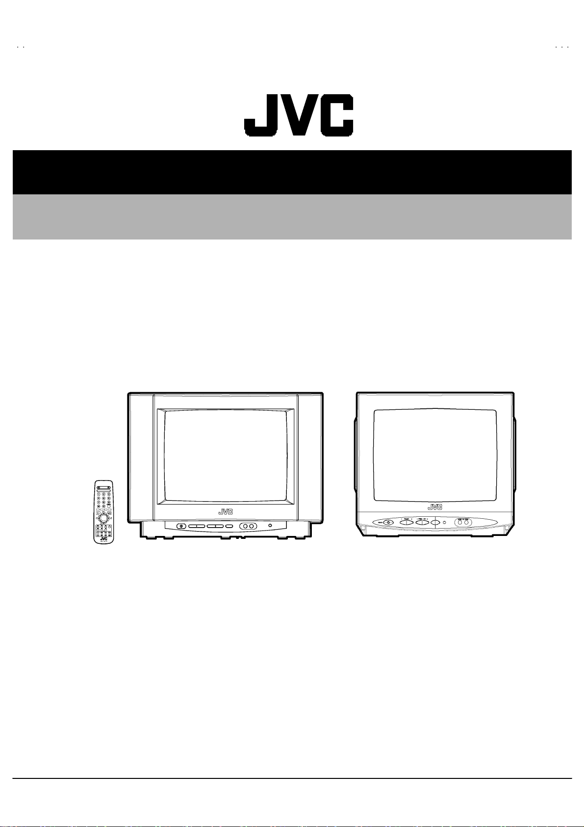
AV14BJ8ENS / AV14BM8ENS
AV14BJ8EPS / AV14BM8EPS
AV14BJ8EES / AV14BM8EES
SERVICE MANUAL
COLOUR TELEVISION
AV14BJ8ENS / AV14BM8ENS AV14BJ8EPS / AV14BM8EPS AV14BJ8EES / AV14BM8EES
AV14BJ8 AV14BM8
CONTENTS
! SPECIFICATIONS ・・・・・・・・・・・・・・・・・・・・・・・・・・・・・・・・
!
SAFETY PRECAUT IONS
!
FEATURES・・・・・・・・・・・・・・・・・・・・・・・・・・・・・・・・
! MAIN DIFFERENCE LIST ・・・・・・・・・・・・・・・・・・・・・・・・・・・・・・・・
!
SPECIFIC SERVICE INSTRUCTIONS
! SERVICE ADJUSTMENTS ・・・・・・・・・・・・・・・・・・・・・・・・・・・・・・・・
! PARTS LIST ・・・・・・・・・・・・・・・・・・・・・・・・・・・・・・・・
★ STANDARD CIRCUIT DIAGRAM・・・・・・・・・・・・・・・・・・・・・・・・・・・・・・・・
1
・・・・・・・・・・・・・・・・・・・・・・・・・・・・・・・・・・・・・・・・・・・・・・・・・・・・・・・・・・・・・・・・
・・・・・・・・・・・・・・・・・・・・・・・・・・・・・・・・・・・・・・・・・・・・・・・・・・・・・・・・・・・・・・・・
・・・・・・・・・・・・・・・・・・・・・・・・・・・・・・・・・・・・・・・・・・・・・・・・・・・・・・・・・・・・・・・・
・・・・・・・・・・・・・・・・・・・・・・・・・・・・・・・・・・・・・・・・・・・・・・・・・・・・・・・・・・・・・・・・
・・・・・・・・・・・・・・・・・・・・・・・・・・・・・・・・
・・・・・・・・・・・・・・・・・・・・・・・・・・・・・・・・・・・・・・・・・・・・・・・・・・・・・・・・・・・・・
・・・・・・・・・・・・・・・・・・・・・・・・・・・・・・・・・・・・・・・・・・・・・・・・・・・・・・・・・・・・・・・・
・・・・・・・・・・・・・・・・・・・・・・・・・・・・・・・・・・・・・・・・・
・・・・・・・・・・・・・・・・・・・・・・・・・・・・・・・・・・・・・・・・・・・・・・・・・・・・・・・・・・・・・・・・
・・・・・・・・・・・・・・・・・・・・・・・・・・・・・・・・・・・・・・・・・・・・・・・・・・・・・・・・・・・・・
・・・・・・・・・・・・・・・・・・・・・・・・・・・・・・・・・・・・・・・・・・・・・・・・・・・・・・・・・・・・・・・・
・・・・・・・・・・・・・・・・・・・・・・・・・・・・・・・・
・・・・・・・・・・・・・・・・・・・・・・・・・・・・・・・・・・・・・・・・・・・・・・・・・・・
・・・・・・・・・・・・・・・・・・・・・・・・・・・・・・・・・・・・・・・・・・・・・・・・・・・・・・・・・・・・・・・・
・・・・・・・・・・・・・・・・・・・・・・・・・・・・・・・・・・・・・・・・・・・・・・・・・・・・・・・・・・・
・・・・・・・・・・・・・・・・・・・・・・・・・・・・・・・・・・・・・・・・・・・・・・・・・・・・・・・・・・・・・・・・
・・・・・・・・・・・・・・・・・・・・・・・・・・・・・・・・・・・・・・・・・・・・・・・・・・・・・・・・・・・・・・・・
・・・・・・・・・・・・・・・・・・・・・・・・・・・・・・・・・・・・・・・・・・・・・・・・・・・・・・・・・・・・・・・・
・・・・・・・・・・・・・・・・・・・・・・・・・・・・・・・・・・・・・・・・・・・・・・・・・・・・・・
・・・・・・・・・・・・・・・・・・・・・・・・・・・・・・・・・・・・・・・・・・・・・・・・・・・・・・・・・・・・・・・・
COPYRIGHT © 2002 VICTOR COMPANY OF JAPAN, LTD.
・・・・・・・・・・・・・・・・・・・・・・・・・・・・・・・・・・・
・・・・・・・・・・・・・・・・・・・・・・・・・・・・・・・・・・・・・・・・・・・・・・・・・・・・・・・・・・・・・・・・
・・・・・・・・・・・・・・・・・・・・・・・・・・・・・
・・・・・・・・・・・・・・・・・・・・・・・・・・・・・・・・・・・・・・・・・・・・・・・・・・・・・・・・・・
・・・・・・・・・・・・・・・・・・・・・・・・・・・・・ 5
・・・・・・・・・・・・・・・・・・・・・・・・・・・・・・・・・・・・・・・・・・・・・・・・・・・・・・・・・・
・・・・・・・・・・・・・・・・・・・・・・・・・・・ 13
・・・・・・・・・・・・・・・・・・・・・・・・・・・・・・・・・・・・・・・・・・・・・・・・・・・・・・
・・・・・・・・・・・・・・・・・・・・・・・・・・・・・・・・・・・・・・・
・・・・・・・・・・・・・・・・・・・・・・・・・・・・・・・・・・・・・・・・・・・・・・・・・・・・・・・・・・・・・・・・
・・・ 2
・・・・・・
・・・・・・・・・ 5
・・・・・・・・・・・・・・・・・・
・・・・・・・・・・・・・・・・・・・
・・・・・・・・・・・・・・・・・・・・・・・・・・・・・・・・・・・・・・
・・・・・・・ 23
・・・・・・・・・・・・・・
・・・・・・・・・・・・・・・・・・・・・・2- 1
・・・・・・・・・・・・・・・・・・・・・・・・・・・・・・・・・・・・・・・・・・・・
No.519 99
Apr. 2002
4
6
Page 2
A
V14BJ8ENS / AV14BM8ENS
A
A
V14BJ8EPS / AV14BM8EPS
V14BJ8EES / AV14BM8EES
SPECIFICATIONS
Content
It em AV14BJ8 ENS
Dimens ions ( W
Mass 9.2 kg 9.8 kg
TV RF System B/G (ENS models) B /G , L/ L’ ( EPS models) B/G , D /K (EES models)
Colour Sy stem
Sound System Mono
Teletext System WST (W orld Standard system)
Receiving Frequency
Intermediate Frequency
Colour Sub Carrier Freq.
Power Input AC 220V~240V , 50Hz
Power Consumpti on 75 W , 8W (Sta nd by)
Aerial Input Term 75 Ωun ba lanc ed, C oaxial
Picture Tube Size Visi ble s ize : 3 4cm, Meas ur ed diagon ally
Hi g h Volt age 25 .5 kV ( at z ero beam current )
Speaker 5cm ×9cm Ova l type×2 Φ8cm round type×2
Au dio Output 8W 3W
REAR TERMINAL(AV1) 21 -pin E uro c onnecto r
FRONT T ERMINAL Video 1Vp- p 75Ω( RCA pin ja ck )
Headphone jack Mini j ac k (φ3. 5m m )
Remote Control Unit VE-300 17763 (RM-C 11 00) , (A A/R 0 6 dry b attery×2)
××××H××××
D ) 44 6mm×3 30mm×3 77mm 37 4mm×3 32mm×3 91mm
PAL, NTSC3.58 / NTSC4.43(Only EXT mode)----ENS model
PAL , SECAM , NTSC3.58 / NTSC4.43(Only EXT mode)----EPS,EES models
VHF (VL) 46 .25 MHz ~ 168. 25 MH z
(VH) 17 5.25MHz ~ 46 3.2 5MHz
UHF 47 1.2 5MHz ~ 86 3.2 5MHz
CATV S1 -S 20& S2 1- S41 &S 75- S7 9 E NS models
S1 -S 20& S2 1- S41 &S 75- S7 9 E PS mo de ls
S1-S20&S21-S41 EES models
VIF Carrier 38 .9 MHz (B/G , D/K , L) / 3 3.9MHz (L’)
SIF Car rier 33.4MHz (5 .5MHz:B/G) / 32. 9MHz (6.0MHz:D/ K ) /32. 4MHz (6.5MHz:L ) /40.4MHz (6.5MHz:L’ )
PAL 4.43MHz
SE CAM 4.2 5MH z / 4.40 62 5MHz
NT S C 3.58MHz / 4.43MHz
Au di o 50 0mVr ms( - 4dBs ) , High Impedance ( RCA pin jack )
AV14 BJ8EPS
AV14 BJ8EES
AV 14 BM 8 EN S
AV 14 BM 8 EPS
AV 14 BM 8 EES
De sign & speci fications are su bject to change wi th ou t no tice.
2
No.51999
Page 3
A
S
A
S
A
S
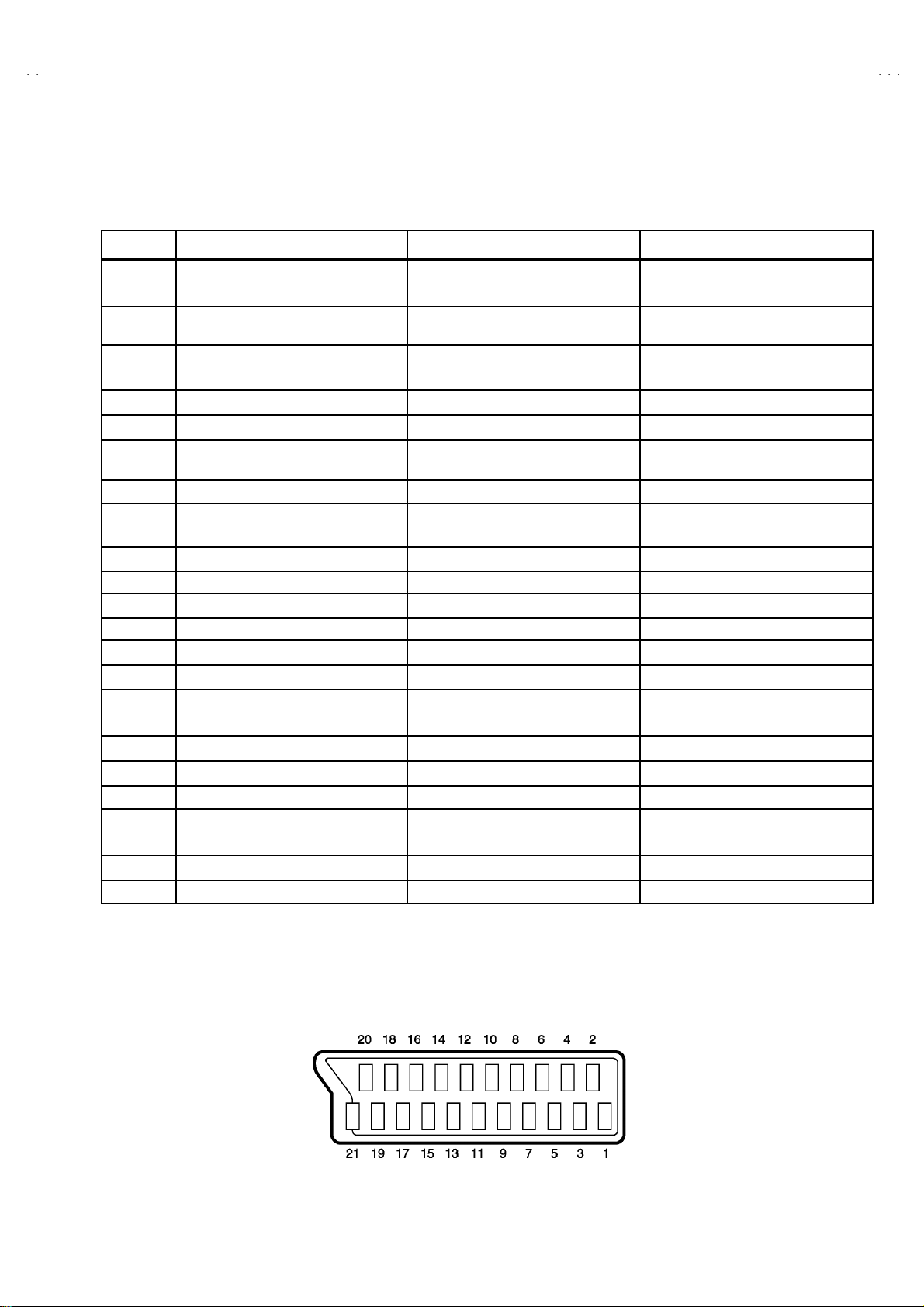
■■■■21-pin Euro connector (SCART socket) : AV-1
(P-P= Peak to Peak, S-W= Sync tip to white peak, B-W= Blanking to white peak)
V14BJ8ENS / AV14BM8EN
V14BJ8EPS / AV14BM8EP
V14BJ8EES / AV14BM8EE
Pin No.
1
2
3
4
5
6
7
8
9
10 SCL3 NC
11 G input 70 0mV
12 SDA3 NC
13 GND (R) ○
14 GND (YS) ○
15
16
17 GND(VIDEO output) ○
18
19
20
21
AUDIO R o utput 50 0mVr ms( N omina l),
AUDIO R i n put 50 0mVrms(Nom i na l),
AUDIO L o utp ut 50 0mVrms(Nom i na l),
AUDIO GND ○
GND (B) ○
AUDIO L input 500mVrms(Nominal),
B in pu t
FUNCTON SW
(SLOW SW)
GND (G) ○
R / C input
Ys i n put
GND(VIDEO input)
VIDEO output
VIDEO / Y inp ut
COM MON G ND ○
Signal Designation Matching Value AV-1
Low impedance
High i mpeda nce
Low impedance
High i mpeda nce
70 0mV
Low : 0-3V, High : 8-12V, High
impedance
R : 700mV
C : 300mV
Low : 0 - 0.4, High : 1 - 3V, 75
1V
1V
, 75Ω○
B- W
, 75Ω○
B- W
, 75Ω
B- W
Ω
, 75
P- P
Ω○
(Nega tive goin g sync ), 75 Ω○
P- P
(Nega tive goin g sync ), 75 Ω○
P- P
○
(TV OUT)
○
○
(TV OUT)
○
○
○
(only R)
○
(TV)
[Pin assignmen t]
No.51999
3
Page 4
A
V14BJ8ENS / AV14BM8ENS
A
A
V14BJ8EPS / AV14BM8EPS
V14BJ8EES / AV14BM8EES
SAFETY PRECAUTIONS
1. The des ign of th is pr od uct con ta in s s p eci al hardware , ma ny
circuit s and components specially for safety pur poses. For
con tinu ed pr ot ection, n o chan ges sh ould b e ma de to the o rig inal
d esi gn un less a uthori zed i n writi n g by th e manu facturer.
Replacement p arts m ust b e ident ic al to thos e used in th e or igin al
ci rcu it s. Se r vic e sh ou ld be performed b y q ua lifie d per sonnel
on ly.
2. Alte rations of t he desig n or cir cuitry of t he pr od ucts s h ould not be
made. Any design alterations or additions will void the
manufact urer 's warr a nt y and w ill f urth er r elieve t he ma nu factu rer
of r esp ons ibility for per sonal inj ury or p roperty dam ag e r esul t in g
th erefr om.
3. Many e lectr i cal an d m ech anica l parts i n th e pr od ucts ha v e
special safety-related characteristics. T hese characteristics are
oft en no t evi den t f r om vi sual i nspecti on n or ca n t he pr o tect ion
aff or de d by th em nece ssar ily b e ob tai n ed b y us ing rep l acemen t
com po ne nts rated f or higher vo ltag e, w att ag e, etc. Rep l acemen t
p arts wh ic h ha ve th ese sp ecial s afet y c h aract er ist ics are
ide ntified in the parts list of S ervic e manua l. El ec tric al
components having su ch features are identified by shading
on the sch e mat ic s an d b y (!!!! ) on the parts list in Service
manual. The us e of a s ub stitute replac ement which do es n ot
h ave the sam e saf ety ch ar act er ist ics as t he r eco mm en de d
replac em ent par t shown i n th e p ar ts lis t of Ser vic e manual m ay
cause shock, fire, or other hazards.
4. Don't shor t between the LIVE s ide ground and ISOLATE D
(NEUTRAL) side ground or EARTH side ground when
repairing.
Some model's power circuit is partly different in the GND. The
diff er enc e of th e GND i s sh ow n by t he LI VE : (") side GND , the
ISO LATE D(NEU TR AL) : (#) side GND an d EA RTH : ($) side
GND. Don't short between the LIVE side GND and
ISO LATE D(NEU TR AL) s ide GN D or EARTH sid e GND an d
n ever m ea sur e w it h a m ea sur i ng a ppa ratus ( osci lloscop e etc.)
th e LI VE sid e GND an d IS OL AT ED(NE UTRAL ) side GND or
EARTH side GND at the same tim e.
If above note will not be kep t, a fuse or any parts will be broken.
5. If any repair has been made to the chassis, it is recommended
th at t he B1 set ting shou l d b e ch ecked or adju s te d ( Se e
ADJUSTMEN T OF B 1 POW E R SUPPL Y).
6. The high vol ta ge app lied t o th e pi cture tu be must c on for m wit h
th at s p eci fi ed in S ervi ce m an ual . E xcessive h i gh volt ag e c a n
cau se an incr e ase i n X- Ray em ission , arc ing and possib le
component damage, therefore operation under excessive high
voltage conditions should be kept to a minimum, or should be
preve nt ed. If s evere arc ing occurs , r emove t he AC power
immed i ate l y and de term i ne th e cause b y visua l insp ect ion
(inc orrec t in stall at i on, crac ke d or m elte d high v o lt age harness,
p oor so ld ering, et c.). To mai nt ai n the p r ope r minimu m level of
sof t X- Ray em ission, c omp on en ts in the high v oltag e ci rcui tr y
including t he pict ur e tu be must be t he e xac t r ep lacem e nts or
alternat ives ap prove d b y th e ma nuf act urer of th e c om plet e
product.
7. Do not c heck hi gh vol t age b y draw ing an arc . U se a hi gh volt age
meter or a hig h v ol tag e pr ob e wit h a VTV M. Dischar g e the
picture tube before attempting meter connection, by connecting
a cl ip lead to th e ground f ra me a nd c onn ectin g the oth er end of
the lead through a 10kΩ 2W resi stor to the an od e b utt on .
8. W hen service is r equ ired, ob ser ve th e origi na l lea d dr ess. E xtra
prec aut i on should b e g i ven t o ass ure cor rect l ea d dr ess in th e
high voltag e ci r cui t a r ea. W here a s hor t cir cuit has occu rred,
th ose co mp on ent s tha t i ndica te ev ide nce of ove r hea ti ng should
b e replac e d. A l ways u se the manuf act urer's replac ement
components.
9. Isolation Check
(Safety for Electrical Shock Hazard)
Af ter re- ass emb ling the p r odu ct, al ways per f orm an i solat ion
ch eck on the expo sed metal p ar ts of t he c abinet (ante nn a
ter mina ls, vid eo /au di o input and ou tpu t termi n als, C on tr ol kn obs,
metal cabinet, screwheads, earphone jack, control shafts, etc.)
to be sure the product i s s af e t o o pe r ate with ou t d an ger of
elect rical shoc k.
(1) Di electric Strength Test
The isolation be tween the A C pr ima ry ci rcu i t an d all me tal p ar ts
exp osed t o th e user, p articularly any e xp osed met al part havi ng a
retu rn path to t he chas s is s ho uld withs tan d a v olt age of 3 000 V
AC (r.m.s.) for a period of one sec ond.
(. . . . Withs tan d a voltage of 1 10 0V AC (r.m. s.) to an appli anc e
rate d up to 12 0V , and 3000V AC (r.m.s.) to an ap plian ce rat ed
200V or more, for a period of one second.)
This method of test requires a t est equipment not g enerally found
in the ser vice trad e.
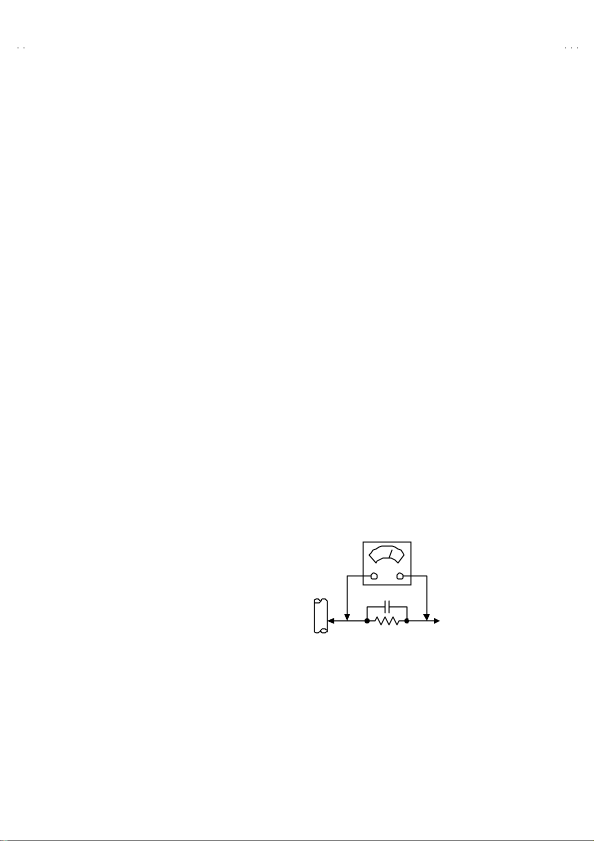
(2) Leakage Current Check
Plug th e A C lin e c ord d ir ect ly into th e A C ou tlet ( d o n ot use a lin e
isolation transf or m er du ring this ch eck.) . U si n g a " Lea kage
Curr ent Tester", me asure the lea kage cu rr e nt f rom each exp osed
metal part of the cabine t, p art icu l arly any e x pos ed me tal p ar t
h avi ng a r e tur n pa th to the ch assis , t o a kn own good earth
ground (wa ter pi p e, e tc.) . An y leaka ge curr en t m ust n ot e x ceed
0.5mA AC (r.m.s.).
However, in tropical ar ea , this must no t exceed 0.2 mA AC
(r.m.s.).
"""" Alternate Check Met ho d
Plug th e A C lin e c ord d ir ect ly into th e A C ou tlet ( d o n ot use a lin e
isolation transfor m er during this che c k.) . U se an AC voltmeter
h avi ng 1 00 0 oh ms pe r volt or m or e sens it i vity in the fo llow ing
manner. Con nec t a 1 50 0Ω 10W res ist or paralle le d b y a 0 .15µF
AC-type capacit or bet we en an expo s ed met al part a nd a kno wn
g ood e arth gro un d (water pi pe , etc.) . M eas ur e th e A C vo lt ag e
acr oss th e res ist or with th e AC v o ltmeter . M ove the res istor
con nec ti on to e ac h exp ose d metal part, p art icul arly a ny exposed
metal part havi n g a retu rn pat h to the chassis , an d m easu r e th e
AC vol tag e ac ross the res ist or. Now, rev erse th e pl u g i n th e AC
ou tlet and r e pe at eac h mea sur em en t. Any vol t ag e me asu red
must no t exc eed 0 .75V AC (r.m.s.). This c orre sponds to 0.5mA
AC (r.m.s.).
Howeve r, in tropical are a, this mu st n ot exceed 0.3V AC ( r .m.s.).
This corresponds to 0.2mA AC (r.m.s.).
AC VOLTMETER
(HAVING 1000 Ω/V,
OR MOR E SENSIT IVITY)
0.15μF AC-TYPE
PLACE THIS PROBE
1500 Ω 10W
GOOD EARTH GROUND
ON E A C H EX PO SE D
ME T AL PA R T
4
No.51999
Page 5
A
S
A
S
A
S
FEATURES
"
This TV set is monaural TV
" The TELETEXT S YSTEM has a built-in WST system.
"
Built-in CHILD LOCK function .
" Bu ilt-i n SLEEP TI ME R fun ction.
MAIN DIFFERENCE LIST
V14BJ8ENS / AV14BM8EN
V14BJ8EPS / AV14BM8EP
V14BJ8EES / AV14BM8EE
Model Name
!!!!
Part Name ENS EPS EES ENS EPS EES
MAIN PWB VE -2 00 962 09 VE -2 00 962 08 VE -2 00 962 07 VE -2 00 962 05 VE -2 00 962 62 VE -2 00 962 10
HE ADPHONE JACK
PWB
!
FRONT CABINET VE-2 0067676 VE-2 0089085
LENS ( FRONT PANEL) VE -2 00 677 13 VE -200 78589
!
SP EAKE R VE -300 01951 VE -3 00109 42
BACK COVER VE -2 00 802 04 VE -200 80407
!
INST BOOK
!
VE -2 00781 06 VE -2 00939 33
VE -5 00264 09 VE-500 26405 VE-50026402 VE-50026409 VE-50026405 VE-50026402
AV 14 BJ 8
AV 14 BM 8
No.51999
5
Page 6

A
V14BJ8ENS / AV14BM8ENS
A
A
V14BJ8EPS / AV14BM8EPS
V14BJ8EES / AV14BM8EES
SPECIFIC SERVICE INSTRUCTIONS
DISASSEMBLY PROCEDURE
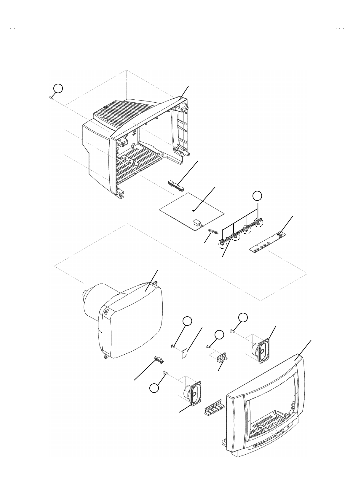
AV14BJ8ENS / EPS / EES
REMOVING THE REAR COVE R
1. Unplug t he po we r c ord.
2. Remove the 5 screws marked A as shown i n the F ig. 1.
3. Withdra w t he r ear co ver to ward y ou .
REMOVING THE MAIN PWB
" Removing the rear cover.
1. Slight ly rai se t he bo th sid es of th e chassis b y h and an d withd raw
th e M AIN PW B ba ckw ard.
(If n ecess ary, take off the wire clamp, co nnectors etc.)
REMOVING THE SPEAKER
" Removing the rear cover.
1. Remov e t he 4 scr ews m arked B, and remov e sp eak er as s hown
in Fig. 1.
REMOVING THE FRONT CONTR OL BOARD
" Removing the rear cover.
"
Removing th e MAIN PWB
1. R emove th e 4 c laws mark ed C from bott om si de att ac h ing t he
CHASSIS BRACKET as shown in the Fig. 1.
2. Remove th e CHASS IS BR ACKET up war d.
3. Pu ll out the FRO NT CO NTROL PW B.
REMOVING THE FRONT AV JACK PWB
"
Removing the rear cover.
" R emoving th e rea r MA IN PW B .
"
Removing the FRONT CONTROL PWB
1. Remove th e 2 scr ews m ar ked D.
2. R emove the FRON T AV JACK PW B .
REMOVING THE HP JACK PWB
" Removing the rear cover.
"
Removing th e MAIN PWB
1. R emove the 1 scr ew s m ar ked E .
2. Remove the HP JACK PWB
CHECKING THE PW BOARD
To c h eck the b ack side of th e PW B oar d.
1) Pu ll out th e PW B oar d. ( R ef er to R EM OV ING TH E MA IN
PWB).
2) Er ect th e PW B oard vert ic al ly so t ha t you c an easil y ch eck
th e b ack side of the PW B oar d.
[CAUTION]
" When erecting t he PW Board, be careful so that there will be no
con tact in g with ot her PW Board.
" Be for e tur n in g on po wer, mak e sur e tha t the wire co nn ector is
properl y con nec ted .
" W hen conducti ng a check wi th p ower su ppl ied, b e sur e to c onfi rm
th at t he CRT E AR TH W I RE (B RA ID ED AS S’Y) is co nne c ted t o
th e CRT SOC KE T PW b oar d.
WIRE CLAMPING AND CABLE TYING
1. Be sure t o cla mp th e wire.
2. N ever r em o ve the c abl e tie use d for tying th e wire s to ge the r.
Should it be inadvertently rem oved, b e sure to tie th e wires with
a n ew c able tie.
6
No.51999
Page 7
A
S
A
S
A
S
REAR COVER
(×1)
(×4)A(×5)
V14BJ8ENS / AV14BM8EN
V14BJ8EPS / AV14BM8EP
V14BJ8EES / AV14BM8EE
PWB
GUIDE RAIL
CRT
ON/OFF
BRACKET
E
HP JACK PWB
MAI N
PWB
CHAS SIS
BRACKET
D
(×2)
CLAW
C
FRONT
C ONT RO L
PWB
B
SP EAKE R
FRONT CABINET
FRONT AV PWB
PWB
GUIDE RAIL
B
(×4)
SP EAKE R
Fig. 1
No.51999
7
Page 8

A
V14BJ8ENS / AV14BM8ENS
A
A
V14BJ8EPS / AV14BM8EPS
V14BJ8EES / AV14BM8EES
DISASSEMBLY PROCEDURE
AV14BM8 ENS / EPS / EES
REMOVING THE REAR COVE R
1. Unplug t he po we r c ord.
2. Remove the 4 screws marked A as shown i n the F ig. 2.
3. Withdra w t he r ear co ver to ward y ou .
REMOVING THE MAIN PWB
"
Removing the REAR COVER.
1. Slight ly r aise t he bot h si d es of th e c hass is b y hand and
withdr aw th e MAIN PWB .
(If n ecess ary, take off the wire clamp, co nnectors etc.)
REMOVING THE FRONT AV JACK PWB
"
Removing the REAR COVER.
" R emove t he MA IN PW B.
1. Remov e th e 2 scr ews m arked B.
2. Remov e t he FRONT AV JACK PWB.
REMOVING THE HP JACK BOARD
"
Removing the REAR COVER.
"
Removing th e MAIN PWB
1. Remov e th e 1 scr ews m arked C.
2. Remove the HP JACK PWB.
CHECKING THE PW BOARD
To c h eck the b ack side of th e PW B oar d.
1) Pu ll out th e PW B oar d. ( R ef er t o R EM OVI NG THE MA IN
PWB).
2) Er ect th e PW Board v ert ic ally so t hat you ca n e asil y ch eck
th e b ack side of the PW B oar d.
[CAUTION]
" When erecting t he PW Board, be careful so that there will be no
con tact in g with ot her PW Board.
" Be for e tur n in g on po wer, mak e sur e tha t the wire co nn ector is
properl y con nec ted .
" W hen conducti ng a check wi th p ower su ppl ied, b e sur e to c onfi rm
th at t he CRT E AR TH W I RE (B RA ID ED AS S’Y) is co nne c ted t o
th e CRT SOC KE T PW b oar d.
WIRE CLAMPING AND CABLE TYING
1. Be sure to cl amp th e wire.
2. Never remo ve th e c able tie used f or tyi ng the w i res to gether.
Sh ould it be ina dvert ent l y re m oved , be sur e t o ti e th e wires with
a n ew c able tie.
8
No.51999
Page 9

A
V14BJ8ENS / AV14BM8EN
S
A
S
A
S
(
)
(
)B(×2)
V14BJ8EPS / AV14BM8EP
V14BJ8EES / AV14BM8EE
A
A
(×4)
(×4)
REAR COVER
REAR COVER
MAI N PWB
MAI N PWB
FUNCTION BOTTOM
FUNCTION BOTTOM
CRT
CRT
C
C
×
×
1
1
FRONT AV PWB
FRONT AV JACK
PWB
HP JACK PWB
HP JACK PWB
SP EAKE R
SP EAKE R
B
(×2)
FRONT CABINET
FRONT CABINET
Fig. 2
Fig. 2
No.51999
9
Page 10

A
V14BJ8ENS / AV14BM8ENS
A
A
V14BJ8EPS / AV14BM8EPS
V14BJ8EES / AV14BM8EES
REPLACEMENT OF CHIP COMPONENT
! CAUTIONS
1. Avoid heating for more than 3 seconds.
2. D o n ot ru b t he el ect rodes an d t he resi st p arts of th e p att ern.
3. W hen r em ovi ng a c hip par t, mel t th e s older adequ ately.
4. D o n ot reuse a ch ip part afte r re moving it.
! SOLDERING IRON
1. U se a hig h ins ulati o n s older ing ir on with a t hin pointed end of it .
2. A 3 0w s older ing ir on is r ec omm end ed for easil y r emoving par ts.
!
REPLACEMENT ST EPS
1. How to remove Chip parts
####
Resistors, capacito rs , etc
(1) As sh own in t he fig ur e, pu sh th e pa rt with tweezer s and
alternat ely m elt the sol de r at each end.
(2) Shift wi th tweeze rs an d r emove th e ch ip part.
#### Tr ans isto rs, dio des, va ria bl e resistors, etc
(1) Apply e xtra solder to ea ch lead.
SOLDE R SOLDE R
2. How to install Chip parts
####
Resistors, capa cit ors , et c
(1) Apply sold er to the pattern as i ndic ated in the fi gure.
(2) Gras p t he chip p art with twee z ers and pl ac e i t on the s ol d er.
The n hea t and melt the so ld er at b oth ends of t he chip part.
#### T ran s ist ors, diodes , varia bl e r esist or s, et c
(1) Apply sold er to the pattern as i ndic ated in the fi gure.
(2) Gras p th e chip p art wit h t we eze rs and plac e it on th e solder .
(3) First solder lead A as indicated in the figu re.
A
(2) As sh own in t he fig ur e, pu sh th e pa rt with tweezer s and
alternat ely m elt th e sold er a t each l e ad . Shift an d remov e t he
chip part.
(4) The n so ld er leads B and C.
Note : After remo ving t he part , remove remaining solder from the
pattern.
10
No.51999
C
A
C
B
B
Page 11

A
S
A
S
A
S
MEMORY IC REPLACEMENT
VALUE
VALUE
ITEM
ITEM
MENU
FUNCTION
1. Memory IC
This model use a memory IC.
Thi s memo r y IC st or es d ata for proper op er atio n of the video
an d d ef l ection circuits.
When replacing, be sure to use an IC containing this (initial
valu e) d ata.
2. Memory IC replacement procedure
(1) Power off
Switch of f t he p ower an d di scon nec t th e po we r co rd fr om
the wall outlet.
V14BJ8ENS / AV14BM8EN
V14BJ8EPS / AV14BM8EP
V14BJ8EES / AV14BM8EE
SE RVICE M ENU
Fig.1
(2) Replace the memory IC
Init ial value must be enter ed i nto the new IC.
(3) Power on
Connect the po wer cor d to t he wall out let an d s wi tch on t he
power.
(4) SERVICE MENU setting
1) Press MENU key an d, whil e th e di spla y ed MENU
screen, press 4, 7, 2, 5 k ey on the rem ote c o ntr ol unit.
2) The SERV ICE M EN U scree n of Fi g.1 i s d isp layed.
3) Veri f y what to set in th e SERV IC E MENU, and set
whatever is necessary (Fi g.1 ). Ref er to the SE RVICE
ADJU STMENT for settin g.
4) Press the MENU key to exit SERVICE MENU.
(5) Receive c hannel setting
Refe r to th e OPERATING INSTR UCTIO NS (USER ’S
GUIDE) and s et the rec e ive channels (Chan nel s P reset ) as
described.
(6) U ser se tting s
Check the us er sett ing items acc ording to aft er pa ge .
Where th ese d o no t agree, r efer to t he OPE RA TING
INSTRUCT IONS (USER’S GUIDE) and set the it ems as
described.
SERVICE MENU SELECT KEY
POWER
NUMBER
SELECT(▲)
SELECT(-)
SELECT(+)
SELECT(▼)
Fig.2
No. 51999
11
Page 12

A
V14BJ8ENS / AV14BM8ENS
A
A
V14BJ8EPS / AV14BM8EPS
V14BJ8EES / AV14BM8EES
SETTING OF THE LAST MEMORY FOR SHIPMENT
■■■■ USER SETTING VALUES
Setting Item Setting Value Setting Ite m Setting Value
SOUND MENU FEATURE MENU
VOL UME 09 SLEEP TIME R OFF
AV L NO CHILD LO CK OFF
PICTURE MENU LANG UAGE ENGL ISH
BRIGHTNES S
COLO UR
CONTRAST
SHAR PNESS
HUE (only NTSC)
Default va lu e : 31 ( all)
12
No. 51999
Page 13

A
S
A
S
A
S
SERVICE ADJUSTMENTS
ADJUSTMENT PREPARATION
1. You can make the necessa ry ad justme nts f or this unit wit h
either the Remote Control Unit or With the adjustment tools
and par ts as give n below.
2. Ad justment with the Remote Control Uni t is made on the
basis of the initial setting v alues, however, the new setting
values which set the screen to its opti mum condition may
differ from t he init ial settin gs.
3. Make sure t hat AC power i s turned on c orrec tl y.
4. Turn on th e power for s et an d test eq ui p me nt bef or e use, and
start t he ad justm en t p rocedures aft er w aiting at least 30 m in ut es.
5. U nl ess o the r wise s pec if ied, prepare t he most s u it ab le rec ep ti on
or inp ut signal for adjust m ent.
6. N ever tou c h any ad j ustment p arts wh ic h ar e n ot s p eci fi ed in t he
list for this adjustment - variable res istors, transformers,
condensers, etc.
7. Pr es etting before ad justm en t.
Unles s ot herwi se spec if i ed i n t he a dj ustme nt ins tr uct ions, pr eset
th e f ollowin g f unctions with th e r e mote c ontrol un it :
BRIGHTNES S
CONTRAST
COLO UR
SHAR PNESS
V14BJ8ENS / AV14BM8EN
V14BJ8EPS / AV14BM8EP
V14BJ8EES / AV14BM8EE
CENTER
ADJUSTMENT EQUIPMENT
1. DC voltmeter (or digital voltmeter)
2. Signal g ener at or (P att ern g ener at or) [PAL/SECAM/NTSC]
3. Remote control unit
MAIN PARTS LOCATIONS
TOP
TOP
TOP
ADJUSTMENT ITEM
!
SCR EEN A DJU ST MEN T
! IF AD JU STM EN T
!
OSD HORIZONTAL ADJUSTMENT
! AGC AUTOMATI CALLY A DJU STM ENT
! DEFLECTION CI RCUIT ADJUSTMENT
!
WHITE BALANCE ADJUSTMENT
FRONT
FRONT
No. 51999
13
Page 14

A
V14BJ8ENS / AV14BM8ENS
A
A
U
y
A
y
V14BJ8EPS / AV14BM8EPS
V14BJ8EES / AV14BM8EES
BASIC OPERATION SERVICE MENU
■■■■ HOW TO ENTER THE SERVICE M ENU
1) Press the MENU key.
2) ME NU sc reen of Fig .1 w ill b e d isp l ayed .
MENU SCRE EN
MEN
SOUND
PICTURE
FEATURE
INSTALL
PROGRAM
Fig.1
3) W hile th e MENU scr ee n is d is played , press the 4,7 ,2 ,5 k ey a nd the
SERV ICE MENU screen of (Fig.2) will be displayed
SE RVICE M ENU
NUMBER key
V ke
REMOTE CONTROL UNI T key NAME
STANDARD
key
COLO UR key
MENU key
FUNCTION
ke
ADJ USTMENT ITEM
Fig.2
■
SEL ECTION OF ADJUSTMENT ITEMS
1) Enter th e SERVICE ME NU
2) Press the FUNC TION / ke y and s elect the SET TING VALUE.
3)
Press the FUNCTION / ke y and s et the settin g value.
SETTING VALUE
■ HOW TO EXIT SERVICE MODE
1) Press the MENU Key on REMOTE CONTROL UNIT.
14
No. 51999
Page 15

A
V14BJ8ENS / AV14BM8EN
S
A
S
A
S
V14BJ8EPS / AV14BM8EP
V14BJ8EES / AV14BM8EE
■
ADJUSTMENT ITEM & INITIAL (Recommended) SETTING VALUE in the SERVICE MENU
ADJ USTMENT ITEM DE SCRIPTION INITIAL VALUE
OSP HORIZONTAL POSI TION OF OS D 064
IF1 IF COARS E ADJU STM ENT 001
IF2 IF FINE ADJUSTMENT 076
IF3 IF COARS E ADJU STM ENT FOR L- P RIME 003
IF4 IF FINE AD JUST MENT FOR L-PRIME 063
AGC AUTOMATIC GA IN CO NT ROL 033
VLIN VERTIC A L LINEARITY 044
VS 1A VE RTICAL SIZE f or 50HZ / 4:3 037
VS 1B VE RTICAL SIZE f or 50HZ / 16:9 059
VP 1 VE RTICAL POSITIO N for 50H
HP1 HORIZON TAL P OSITION for 50H
VS 2A VE RTICAL SIZE f or 60HZ / 4:3 008
VS 2B VE RTICAL SIZE f or 60HZ / 16:9 037
VP 2 VE RTICAL POSITIO N for 60H
HP2 HORIZON TAL P OSITION for 60H
RGBH RGB MODE HORIZONTAL SHI FT OFFSET 031
WR W H ITE POINT ADJUSTMENT FO R RE D 040
WG W HITE POINT ADJU STMENT FO R GREEN 04 0
WB W HITE POINT AD JU STME NT FOR BLUE 04 0
BR BIA S FOR RED 031
BG BIAS FOR G REEN 031
AP R AU TOM ATIC R GB PEA K REGUL ATION THRESHOLD 01 0
FMP1 FM PRESCALER W HEN AV L IS OFF 009
NIP1 NIC AM PRESC A LER W HEN A VL IS OF F 02 0
SCP1 SC ART P RESCALE R WH EN AVL IS O FF 01 3
FMP2 FM PRESCALER W HEN AV L IS ON 01 3
NZP2 FM PRESC A LER W HEN AV L IS ON 01 6
SCP2 F M PRESCALER W HEN AV L IS ON 01 3
F1H HIGH BYTE OF VHF1-VHF3 CROSS-OVER FREQUENCY 0000 1001
F1L LOW BYTE O F VHF1- VHF3 CROSS -O VER FREQ UENCY 10 01 00 10
F2H HIGH BYTE OF VHF3-UHF CROSS-OVER FREQUENCY 00011011
F2L LOW BYTE O F VHF3- UHF CR OS S-OVER F REQ UE NCY 10 00 00 10
BS 1 BAND SW ITCHIN G B YTE FOR VHF1 00 00 00 11
BS 2 BAND SW ITCHIN G B YTE FOR VHF3 00 00 01 10
BS 3 BAND SW ITCHIN G B YTE FOR UHF 10 00 01 01
CB CONTROL BYTE 10 00 11 10
OP1 PERIPHERAL OPTIONS 01 10 11 01
OP2 RECEPTI ON STANDARD OPTIONS 01 011000
OP3 VIDEO OPTI ONS 11 1101 01
OP4 TU FEATURRES 01 10 10 11
OP5 C HANNEL TA BLES 11 01 10 11
TX1 TELE TEXT OPTIONS 00 00 01 10
Z
Z
Z
Z
00 8
03 5
01 3
02 3
DO NOT ADJUST
No. 51999
15
Page 16

AV14BJ8ENS / AV14BM8ENS
r
AV14BJ8EPS / AV14BM8EPS
AV14BJ8EES / AV14BM8EES
ADJUSTMENTS
■
■ SCREEN ADJUSTMENT
■■
Item
SCREEN
adjustment
■
■ ADJUSTMENT
■■
Measuring
instrument
Remote
control unit
Test point Adjustment part Description
SCREEN VR
[On the FBT]
1. Enter SERVICE MENU.
2. Press YELLOW key to disable vertical scan.
3. Adjust SCREEN VR. on the FBT for a thin horizontal line like a
figure.
4. Press YE LLOW key again to enable vertical scan.
5. Press MENU key to leave service menu.
Item
IF adjustment Remote
■
■ OSD HORIZONTAL POSITION ADJUSTMENT
■■
Item
HORIZONTAL
POSITION OF
OSD
adjustment
Measuring
instrument
control unit
Measuring
instrument
Remote
control unit
Test point Adjustment part Description
IF 1
IF 2
IF 3
IF 4
Test point Adjustment part Description
OSD
SERVICE MENU SCREEN
1. Enter SERVICE MENU.
2. Select IF 1 with FUNCTION ( / ) key
3. Press BLUE key during IF 1 is highlighted, IF 1 and IF 2 values
are adjusted automatically by software.
4. If the standard is L-prime, IF 3 and IF 4 values are adjustment
automatically when BLUE key is pressed during IF 1 is
highlighted.
1. Enter SERVICE MENU.
2. Select OSD with FUNCTION ( / ) key
3. Adjust the OSD horizontal position with the FUNCTION ( / )
key, which shifts the reference bar on the bottom of the
SERVICE MENU horizontally, so that the OSD is positioned on
the screen center. (X=X’)
16
Reference ba
X X’
Screen s ize
No. 51999
Page 17

A
S
A
S
A
S
■■■■ AGC AUTOMAT ICALLY ADJUSTMENT
S
Item
AG C
AUTOMATICAL LY
adjust ment
& check
Measuring
instrume nt
Remote
control unit
ERVICE MENU SCREEN
Test point Ad justment part Des cription
AG C 1. En ter SERVIC E MENU.
■■■■ DEFLECTION C IRCUIT
Item
VERT ICAL
LINEARITY
adjust ment
Measuring
instrume nt
Signal
gener ator
Remote
control unit
Test point Ad justment part Des cription
VLIN 1. Receive a PAL B/G circle pattern.
V14BJ8ENS / AV14BM8EN
V14BJ8EPS / AV14BM8EP
V14BJ8EES / AV14BM8EE
2. Receive a 60dBμV RF signal level.
3. Se lect AG C from SE RVICE MENU .
4. Pr ess BLUE ke y on th e r emot e co ntrol uni t.
5. Then the adjustment will be done automatically by software.
6. Se e the AGC ind ic ator on SERVICE MENU , i t m ust be “1” .
7. C heck th at p ict ure i s norm al a t 90 dB μV signal level.
:11
IF INDICATOR AGC INDICATOR NONE
2. En ter SERVIC E MENU.
3. Select VLIN wi th the FUNCTION ( / ) key.
4. Ad just VL IN w it h t he F UNCTION ( / ) key until circle as
round as p ossible.
5. Pr ess the ME NU key and mem oriz e th e s et value.
VERTICAL
SIZ E
adjust ment
(50Hz , 4: 3)
very close
Scr een
size
very close
Signal
gener ator
Remote
control unit
VS1A 1. Rec eive a PA L B/G ci r cl e p att ern of ve rtica l fr equ en cy 5 0Hz.
2. En ter SERVIC E MENU.
3. Select VS1A w ith th e FUNCTION ( / ) key.
4. Ad just VS1 A with the FUNCTION ( / ) key un til horizontal
blac k lin es on b oth the u pp er a nd l ow er p ar t of th e ci r cl e
pattern become very close to the upper and lower horizontal
si des of pic tu re si ze and nearl y about to disa ppear .
5. Chec k and readjus t VS 1A item if t he ad justm en t b ec om es
impr ope r aft er some oth er geomet ric adjus t m ents are d one.
Picture
size
10 0%
No. 51999
17
Page 18

A
V14BJ8ENS / AV14BM8ENS
A
A
g
V14BJ8EPS / AV14BM8EPS
V14BJ8EES / AV14BM8EES
Item
VERTICAL
SIZ E
adjust ment
(50Hz , 16 :9)
16 :9
format
screen
size
VERTICAL
POSITION
adjust ment
(50Hz )
Measurin
instrume nts
Signal
gener ator
Remote
control unit
16:9 S CREEN
Signal
gener ator
Remote
control unit
Test point Ad justment part Des cription
VS1B 1. R eceive a PAL B/G c ross-h atch p att er n of ver tical frequ enc y
50 Hz.
2. En ter SERVIC E MENU.
3. Select VS 1B with the FUNCTION ( / ) key.
4. Press GREEN key to switch t o 16:9 screen mode.
5. Ad just VS1 B with t he FUNCTION ( / ) key unti l the s creen
become 16:9 format.
6. Chec k and re adj us t VS1 B i tem if th e adjustm ent be com es
impr ope r aft er some oth er geomet ric adjus t m ents are d one.
Picture
size
10 0%
VP 1 1. Recei ve a PA L B/G circ le patt er n si g nal of vert ic al f re qu enc y
50 Hz.
2. En ter SERVIC E MENU.
3. Select VP1 with the FUNCT ION ( / ) key.
4. Adjust VP 1 with the FU NCTION ( / ) key unti l the circle
pattern is vertically centered.(A=B)
5. Chec k and re ad ju st V P1 ite m if t he ad j ustmen t bec om es
impr ope r aft er some oth er geomet ric adjus t m ents are d one.
A
HORIZONTAL
POSITION
adjus tment
(50Hz )
18
Signal
Generator
Remote
control unit
C
B
HP1 1. R eceiv e a PA L B/G ci rc le p att er n sig nal of vertical freque ncy
50 Hz.
2. En ter SERVIC E MENU.
3. Select HP1 with the FUNCTION ( / ) key.
4. Adjust HP1 wi th the FUNCTIO N ( / ) key until the ci rcle
p atter n i s h orizo ntal ly cente r ed.( C=D)
D
5. Chec k and re ad ju st HP 1 it em if the a djust me nt bec om es
impr ope r aft er some oth er geomet ric adjus t m ents are d one.
No. 51999
Page 19

A
V14BJ8ENS / AV14BM8EN
S
A
S
A
S
g
V14BJ8EPS / AV14BM8EP
V14BJ8EES / AV14BM8EE
Item
VERTICAL
SIZ E
adjus tment
(60Hz , 4: 3)
Very clos e
Scr een
size
Very clos e
Measurin
instrume nts
Signal
gener ator
Remote
control unit
Test point Ad justment part Des cription
VS2A 1. R eceive a PAL B/G cross- h atch p att ern of ver ti cal frequ enc y
60Hz.
2. Enter SE RVICE M ENU.
3. Select VS 2A wi th the FUNCTION ( / ) key.
4. Ad just VS2A wi th t he FUNCTION ( / ) key un ti l th e
h oriz o nt al blac k l ines on b oth t he upp er and low er p art of the
circle pattern become very close to the upper and lower
h oriz o nt al sid es of pic tur e si ze and nearl y about to disap pear .
5. Check a nd r e adjus t VS2A item if the adju s tm ent be comes
impr ope r aft er some oth er geomet ric adjus t m ents are d one.
Picture
size
10 0%
VERT ICAL
SIZ E
adjust ment
(60Hz , 16 :9)
16 :9
format
screen
size
Signal
gener ator
Remote
control unit
16:9 S CREEN
VS 2B 1. R eceive a PAL B/G cross- h atch p att ern of ver ti cal frequ enc y
60Hz.
2. Enter SE RVICE M ENU.
3. Select VS 2B wi th the FUNCTION ( / ) key.
4. Press GREEN key to swi tch t o 16:9 screen m ode.
5. Adjust VS2B with t he FUNCTION ( / ) key until the s creen
become 16:9 format.
6. Check a nd r e adjus t VS2B item if the adju s tm ent be comes
impr ope r aft er some oth er geomet ric adjus t m ents are d one.
Picture
size
10 0%
No. 51999
19
Page 20

A
V14BJ8ENS / AV14BM8ENS
A
A
g
V14BJ8EPS / AV14BM8EPS
V14BJ8EES / AV14BM8EES
Item
VERTICAL
POSITION
adjus tment
(60Hz )
HORIZONTAL
POSITION
adjus tment
(60Hz )
Measurin
instrume nts
Signal
gener ator
Remote
control unit
Signal
gener ator
Remote
control unit
C
Test point Ad justment part Des cription
VP2 1. Recei ve a PA L B/G circ le patt er n si g nal of vert ic al f re qu enc y
60Hz.
2. En ter SERVIC E MENU.
3. Select VP2 with the FUNCT ION ( / ) key.
4. Adjust VP 2 with the FU NCTION ( / ) key unti l the circle
pattern is vertically centered.(A=B)
5. Chec k and re ad ju st V P2 ite m if t he ad j ustmen t bec om es
A
B
HP2 1. R eceiv e a PA L B/G ci rc le p att er n sig nal of vertical freque ncy
D
impr ope r aft er some oth er geomet ric adjus t m ents are d one.
60Hz.
2. En ter SERVIC E MENU.
3. Select HP2 with the FUNCTION ( / ) key.
4. Adjust HP2 wi th the FUNCTIO N ( / ) key until the ci rcle
p atter n i s h orizo ntal ly cente r ed.( C=D)
5. Chec k and re ad ju st HP 2 it em if the a djust me nt bec om es
impr ope r aft er some oth er geomet ric adjus t m ents are d one.
R GB M ODE
HORIZONTAL
SHIFT
OFF SET
adjus tment
20
Signal
gener ator
Remote
control unit
E
RGBH 1. Input R/G/B circle pattern signal via video inpu t te r minal.
2. Pr ess AV k ey on the r emo te control u nit.
3. En ter SERVIC E MENU.
4. Select RGBH with th e FUNCTION ( / ) key.
5. Adjust RGBH with the FUNCTION ( / ) key until the circle
p atter n i s h orizo ntal ly cente r ed.( E=F)
6. Chec k and r ead ju st RGBH it em i f the adj ustment be com es
F
impr ope r aft er some oth er geomet ric adjus t m ents are d one.
No. 51999
Page 21

A
S
A
S
A
S
■■■■ WHITE BALANCE ADJUS TM ENT
Item
WHITE
BALANCE
adjust ment
(Low light)
Measuring
instrume nt
Signal
gener ator
Remote
control unit
Test point Ad justment part Des cription
Recom mended value 04 0 04 0 04 0
V14BJ8ENS / AV14BM8EN
V14BJ8EPS / AV14BM8EP
V14BJ8EES / AV14BM8EE
WR
WG
WB
It em WR WG W B
1. R ecei ve a bla ck & wh it e si gn al (co l our of f) .
2. En ter SERVIC E MENU.
3. Select WR / WG / WB w ith t he ( / ) key, respecti ve ly.
4. Adju st W R / W G / WB with the FUNCTION ( / ) key,
resp ectively, unt il the whit e part tu rns to pure whit e witho ut any
other color..
WHITE
BALANCE
adjust ment
(Hi gh light)
Signal
gener ator
Remote
control unit
BR
BG
It em BR BG
Recom mended value 04 0 040
1. R ecei ve a bla ck & wh it e si gn al (co l our of f)
2. En ter SERVIC E MENU.
3. Select BR / BG with the FUNCTION ( / ) key r espectively.
4. Ad just BR / BG with the FUNCTION ( / ) key r espectively
un til the whi te part of screen make whi te colo ur.
No. 51999
21
Page 22

A
V14BJ8ENS / AV14BM8ENS
A
A
V14BJ8EPS / AV14BM8EPS
V14BJ8EES / AV14BM8EES
< M E M O >
22
No. 51999
 Loading...