

JVC 86652ien Service Manual

ENGLISH
CONTENTS
AUTOMATIC
DEMONSTRATION
GETTING STARTED 9 – 18
8
DIGITAL VIDEO CAMERA
GR-DVP3
Please visit our Homepage on the World Wide
Web and answer our Consumer Survey
(in English only):
http://www.jvc-victor.co.jp/english/index-e.html
INSTRUCTIONS
VIDEO RECORDING &
PLAYBACK 19 – 26
VIDEO RECORDING ............. 20 – 22
VIDEO PLAYBACK ............... 23 – 26
DIGITAL STILL CAMERA (D.S.C.)
RECORDING &
PLAYBACK 27 – 38
D.S.C. RECORDING .............. 28 – 29
D.S.C. PLAYBACK ................ 30 – 38
ADVANCED
FEATURES 39 – 75
USING MENUS FOR
DETAILED ADJUSTMENT ...... 40 – 46
FOR RECORDING ................ 47 – 57
DUBBING ......................... 58 – 61
USING THE REMOTE
CONTROL UNIT ................ 62 – 73
SYSTEM CONNECTIONS ........ 74 – 75
REFERENCES 76 – 99
DETAILS ................................... 77
TROUBLESHOOTING ............ 78 – 83
USER MAINTENANCE ................... 84
INDEX ............................. 85 – 92
CAUTIONS ........................ 93 – 95
TERMS ............................ 96 – 97
SPECIFICATIONS ................. 98 – 99
For Customer Use:
Enter below the Model No. and Serial No. which is located on the
bottom of cabinet. Retain this information for future reference.
Model No.
Serial No.
LYT0795-001B
EN

2 EN
Dear Customer,
Thank you for purchasing this digital video camera. Before use, please read the safety information and precautions
contained in the following pages to ensure safe use of this product.
Using This Instruction Manual
• All major sections and subsections are listed in the Table Of Contents on the cover page.
• Notes appear after most subsections. Be sure to read these as well.
• Basic and advanced features/operation are separated for easier reference.
It is recommended that you . . .
..... refer to the Index (墌 pgs. 85 – 92) and familiarize yourself with button locations, etc. before use.
..... read thoroughly the Safety Precautions and Safety Instructions that follow. They contain extremely important
information regarding the safe use of this product.
You are recommended to carefully read the cautions on pages 93 through 95 before use.
SAFETY PRECAUTIONS
CAUTION
RISK OF ELECTRIC SHOCK
DO NOT OPEN
CAUTION: TO REDUCE THE RISK OF ELECTRIC SHOCK,
DO NOT REMOVE COVER (OR BACK).
NO USER-SERVICEABLE PARTS INSIDE.
REFER SERVICING TO QUALIFIED SERVICE PERSONNEL.
The lightning flash with arrowhead symbol, within an
equilateral triangle, is intended to alert the user to the
presence of uninsulated "dangerous voltage" within the
product's enclosure that may be of sufficient magnitude
to constitute a risk of electric shock to persons.
The exclamation point within an equilateral triangle is
intended to alert the user to the presence of important
operating and maintenance (servicing) instructions in
the literature accompanying the appliance.
The AA-V100U AC Power Adapter/Charger should
be used with:
AC 120 V`, 60 Hz in the USA and Canada,
AC 110 V – 240 V`, 50 Hz/60 Hz in other countries.
CAUTION (applies to the AA-V100U)
TO PREVENT ELECTRIC SHOCK MATCH WIDE
BLADE OF PLUG TO WIDE SLOT, FULLY INSERT.
ATTENTION (s’applique à l’AA-V100U)
POUR ÉVITER LES CHOCS ÉLECTRIQUES,
INTRODUIRE LA LAME LA PLUS LARGE DE LA
FICHE DANS LA BORNE CORRESPONDANTE DE
LA PRISE ET POUSSER JUSQU’AU FOND.
WARNING:
TO PREVENT FIRE OR SHOCK
HAZARD, DO NOT EXPOSE
THIS UNIT TO RAIN OR
MOISTURE.
NOTES:
●
The rating plate (serial number plate) and safety
caution are on the bottom and/or the back of the
main unit.
●
The rating plate (serial number plate) of the AC
Power Adapter/Charger is on its bottom.
CAUTIONS:
● This camcorder is designed to be used with NTSC-
type color television signals. It cannot be used for
playback with a television of a different standard.
However, live recording and LCD monitor/
viewfinder playback are possible anywhere.
● Use the JVC BN-V107U/V114U battery packs
and, to recharge them or to supply power to the
camcorder from an AC outlet, use the provided
multi-voltage AC Power Adapter/Charger. (An
appropriate conversion adapter may be necessary
to accommodate different designs of AC outlets in
different countries.)
Caution: (applies to Docking Station)
To reduce the risk of fire, do not remove
cover. No user-serviceable parts inside.
Refer servicing to qualified service person.

EN3
When the equipment is installed in a cabinet or on a shelf, make sure that it has sufficient space on all sides to
allow for ventilation (10 cm (3-15/16") or more on both sides, on top and at the rear).
Do not block the ventilation holes.
(If the ventilation holes are blocked by a newspaper, or cloth etc. the heat may not be able to get out.)
No naked flame sources, such as lighted candles, should be placed on the apparatus.
When discarding batteries, environmental problems must be considered and the local rules or laws governing the
disposal of these batteries must be followed strictly.
The apparatus shall not be exposed to dripping or splashing.
Do not use this equipment in a bathroom or places with water.
Also do not place any containers filled with water or liquids (such as cosmetics or medicines, flower vases, potted
plants, cups etc.) on top of this unit.
(If water or liquid is allowed to enter this equipment, fire or electric shock may be caused.)
Do not point the lens or the viewfinder directly into the sun. This can cause eye injuries, as well as lead to the
malfunctioning of internal circuitry. There is also a risk of fire or electric shock.
CAUTION!
The following notes concern possible physical damage to the camcorder and to the user.
When carrying, be sure to always securely attach and use the provided strap. Carrying or holding the
camcorder by the viewfinder and/or the LCD monitor can result in dropping the unit, or in a malfunction.
Take care not to get your finger caught in the cassette holder cover. Do not let children operate the camcorder, as
they are particularly susceptible to this type of injury.
Do not use a tripod on unsteady or unlevel surfaces. It could tip over, causing serious damage to the camcorder.
CAUTION!
Attaching the camcorder to the Docking Station with cables (S-Video, Editing, etc.) connected, then leaving it on
top of the TV is not recommended, as tripping on the cables will cause the camcorder to fall, resulting in damage.
Attach only the optional JVC VL-V3U Video Light, VL-F3U Video Flash or MZ-V3U Stereo Zoom Microphone to the camcorder’s Info-Shoe.
䡲 This camcorder is designed exclusively for the digital video cassette, SD Memory Card and
MultiMediaCard. Only cassettes marked “ ” and memory cards marked “ ” or
“
” can be used with this unit.
Before recording an important scene . . .
.... make sure you only use cassettes with the Mini DV mark .
.... make sure you only use memory cards with the mark
.... remember that this camcorder is not compatible with other digital video formats.
.... remember that this camcorder is intended for private consumer use only. Any commercial
use without proper permission is prohibited. (Even if you record an event such as a show,
performance or exhibition for personal enjoyment, it is strongly recommended that you
obtain permission beforehand.)
or .

4 EN
IMPORTANT PRODUCT
SAFETY INSTRUCTIONS
Electrical energy can perform many useful functions.
But improper use can result in potential electrical
shock or fire hazards. This product has been
engineered and manufactured to assure your
personal safety. In order not to defeat the built-in
safeguards, observe the following basic rules for its
installation, use and servicing.
ATTENTION:
Follow and obey all warnings and instructions
marked on your product and its operating instructions. For your safety, please read all the safety and
operating instructions before you operate this
product and keep this manual for future reference.
INSTALLATION
1. Grounding or Polarization
(A) Your product may be equipped with a polarized
alternating-current line plug (a plug having one blade
wider than the other). This plug will fit into the
power outlet only one way. This is a safety feature.
If you are unable to insert the plug fully into the
outlet, try reversing the plug. If the plug should still
fail to fit, contact your electrician to replace your
obsolete outlet. Do not defeat the safety purpose of
the polarized plug.
(B) Your product may be equipped with a 3-wire
grounding-type plug, a plug having a third (grounding) pin. This plug will only fit into a grounding-type
power outlet. This is a safety feature.
If you are unable to insert the plug into the outlet,
contact your electrician to replace your obsolete
outlet. Do not defeat the safety purpose of the
grounding-type plug.
2. Power Sources
Operate your product only from the type of power
source indicated on the marking label. If you are not
sure of the type of power supply to your home, consult
your product dealer or local power company. If your
product is intended to operate from battery power, or
other sources, refer to the operating instructions.
3. Overloading
Do not overload wall outlets, extension cords, or integral
convenience receptacles as this can result in a risk of fire
or electric shock.
4. Power Cord Protection
Power supply cords should be routed so that they are
not likely to be walked on or pinched by items placed
upon or against them, paying particular attention to
cords at plugs, convenience receptacles, and the point
where they exit from the product.
5. Ventilation
Slots and openings in the cabinet are provided for
ventilation. To ensure reliable operation of the product
and to protect it from overheating, these openings must
not be blocked or covered.
•Do not block the openings by placing the product on a
bed, sofa, rug or other similar surface.
•Do not place the product in a built-in installation such
as a bookcase or rack unless proper ventilation is
provided or the manufacturer’s instructions have been
adhered to.
6. Wall or Ceiling Mounting
The product should be mounted to a wall or ceiling only
as recommended by the manufacturer.
ANTENNA INSTALLATION
INSTRUCTIONS
1. Outdoor Antenna Grounding
If an outside antenna or cable system is connected to the
product, be sure the antenna or cable system is
grounded so as to provide some protection against
voltage surges and built-up static charges. Article 810 of
the National Electrical Code, ANSI/NFPA 70, provides
information with regard to proper grounding of the mast
and supporting structure, grounding of the lead-in wire
to an antenna discharge unit, size of grounding
conductors, location of antenna discharge unit,
connection to grounding electrodes, and requirements
for the grounding electrode.
2. Lightning
For added protection for this product during a lightning
storm, or when it is left unattended and unused for long
periods of time, unplug it from the wall outlet and
disconnect the antenna or cable system. This will
prevent damage to the product due to lightning and
power-line surges.
3. Power Lines
An outside antenna system should not be located in the
vicinity of overhead power lines or other electric light or
power circuits, or where it can fall into such power lines
or circuits. When installing an outside antenna system,
extreme care should be taken to keep from touching
such power lines or circuits as contact with them might
be fatal.
EXAMPLE OF ANTENNA GROUNDING AS PER
NATIONAL ELECTRICAL CODE, ANSI/NFPA 70
ANTENNA
LEAD IN WIRE
GROUND CLAMP
ANTENNA
DISCHARGE UNIT
(NEC SECTION
ELECTRIC SERVICE
EQUIPMENT
POWER SERVICE GROUNDING ELECTRODE SYSTEM
(NEC ART 250. PART H)
NEC – NATIONAL ELECTRICAL CODE
810-20)
GROUNDING CONDUCTORS
(NEC SECTION 810-21)
GROUND CLAMPS

EN5
USE
1. Accessories
To avoid personal injury:
•Do not place this product on an unstable cart,
stand, tripod, bracket or table. It may fall, causing
serious injury to a child or adult, and serious
damage to the product.
•Use only with a cart, stand, tripod, bracket, or table
recommended by the manufacturer or sold with the
product.
•Use a mounting accessory recommended by the
manufacturer and follow the manufacturer’s
instructions for any mounting of the product.
•Do not try to roll a cart with small casters across
thresholds or deep-pile carpets.
2. Product and Cart
Combination
A product and cart
combination should be
moved with care. Quick
stops, excessive force, and
uneven surfaces may cause
the product and cart
combination to overturn.
3. Water and Moisture
Do not use this product near water—for example,
near a bath tub, wash bowl, kitchen sink or laundry
tub, in a wet basement, or near a swimming pool and
the like.
4. Object and Liquid Entry
Never push objects of any kind into this product
through openings as they may touch dangerous
voltage points or short-out parts that could result in a
fire or electric shock. Never spill liquid of any kind
on the product.
5. Attachments
Do not use attachments not recommended by the
manufacturer of this product as they may cause
hazards.
6. Cleaning
Unplug this product from the wall outlet before
cleaning. Do not use liquid cleaners or aerosol
cleaners. Use a damp cloth for cleaning.
7. Heat
The product should be situated away from heat
sources such as radiators, heat registers, stoves, or
other products (including amplifiers) that produce
heat.
PORTABLE CART WARNING
(Symbol provided by RETAC)
SERVICING
1. Servicing
If your product is not operating correctly or exhibits a
marked change in performance and you are unable
to restore normal operation by following the detailed
procedure in its operating instructions, do not
attempt to service it yourself as opening or removing
covers may expose you to dangerous voltage or other
hazards. Refer all servicing to qualified service
personnel.
2. Damage Requiring Service
Unplug this product from the wall outlet and refer
servicing to qualified service personnel under the
following conditions:
a. When the power supply cord or plug is damaged.
b. If liquid has been spilled, or objects have fallen
into the product.
c. If the product has been exposed to rain or water.
d. If the product does not operate normally by
following the operating instructions. Adjust only
those controls that are covered by the operating
instructions as an improper adjustment of other
controls may result in damage and will often
require extensive work by a qualified technician
to restore the product to its normal operation.
e. If the product has been dropped or damaged in
any way.
f. When the product exhibits a distinct change in
performance—this indicates a need for service.
3. Replacement Parts
When replacement parts are required, be sure the
service technician has used replacement parts
specified by the manufacturer or have the same
characteristics as the original part. Unauthorized
substitutions may result in fire, electric shock or other
hazards.
4. Safety Check
Upon completion of any service or repairs to this
product, ask the service technician to perform safety
checks to determine that the product is in safe
operating condition.

6 EN
PROVIDED ACCESSORIES
• Docking Station
CU-V507U
• Remote Control Unit
RM-V717U
• Memory Card 8 MB
(Already inserted in the
camcorder)
• AC Power Adapter/Charger
AA-V100U
• DC Cord
• CD-ROM
• Battery Pack
BN-V107U
• AAA (R03) Battery x 2
(for remote control unit)
• Editing Cable
• Audio/Video Cable
(ø3.5 mini-plug to RCA plug)
NOTE:
In order to maintain optimum performance of the camcorder, provided cables may be equipped
with one or more core filter. If a cable has only one core filter, the end that is closest to the filter
should be connected to the camcorder.
• Grip Belt •Strap
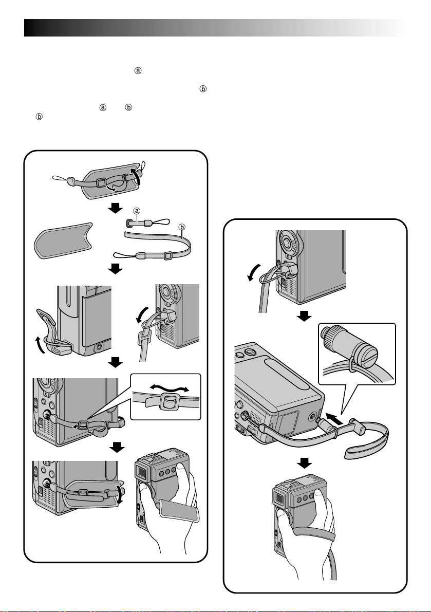
How To Attach The Grip Belt
1 Remove the pad and separate the two straps.
2 Thread one end of the strap through the
eyelet, then pass the other end through the loop.
3 Repeat the same procedure to attach the strap
to the other eyelet.
4 Connect the strap and
through the buckle, then adjust the grip
(墌 pg. 12).
5 Attach the pad.
and thread the strap
1
EN7
How To Attach The Strap
1 Thread one end of the strap through the eyelet,
then pass the other end through the loop.
2 Attach the screw to the tripod mounting socket.
To tighten the screw firmly, use a coin, etc.
3 Adjust the length with the adjuster.
NOTES:
●
You can use the strap as a shoulder strap by
adjusting the length with the adjuster.
●
Because the screw may cause damage to the
camcorder, make sure to attach the screw to the
tripod mounting socket when carrying the
camcorder.
●
Use the strap only with this camcorder.
●
Do not grip the camcorder too firmly when the
screw is attached. Doing so may cause damage to
the tripod mounting socket.
1
2
5
4
3
2
3
8 EN
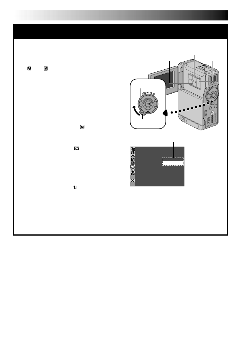
AUTOMATIC DEMONSTRATION
Automatic Demonstration takes place
when “DEMO MODE” is set to “ON”
(factory-preset).
䡲 Available when the Power Switch is set to
“ ” or “ ” and no cassette is in the
camcorder.
䡲 Performing any operation during the demon-
stration stops the demonstration temporarily. If
no operation is performed for more than 1
minute after that, the demonstration will
resume.
䡲 “DEMO MODE” remains “ON” even if the
camcorder power is turned off.
䡲 To cancel Automatic Demonstration:
1. Set the Power Switch to “ ” while
pressing down the Lock Button located on
the switch and press MENU. The Menu
Screen appears.
2. Press + or – to select “ SYSTEM” and
press SET/SELECT. The SYSTEM Menu
appears.
3. Press + or – to select “DEMO MODE” and
press SET/SELECT. The Sub Menu appears.
4. Press + or – to select “OFF” and press SET/
SELECT.
5. Press + or – to select “ RETURN”, and
press SET/SELECT twice. The normal screen
appears.
NOTE:
If you do not slide the lens cover down, you
cannot see the actual changes of the Automatic
Demonstration activated on the LCD monitor or
viewfinder.
MENU Button
+, – ButtonSET/SELECT Button
Power Switch
Lock Button
Sub Menu
MOD EDEMO –ONOFF

GETTING STARTED
Power
EN9
GETTING STARTED
CONTENTS
.................................................................. 10 – 11
Grip Adjustment
Viewfinder Adjustment
Tripod Mounting
Date/Time Settings
Loading/Unloading A Cassette
Recording Mode Setting
Loading A Memory Card
Picture Quality Mode Setting
Image Size Mode Setting .........................................................
Operation Mode
............................................................. 12
.................................................... 12
............................................................. 12
......................................................... 13
........................................... 14
................................................... 15
................................................... 16
............................................. 17
............................................................. 18
17

10 EN
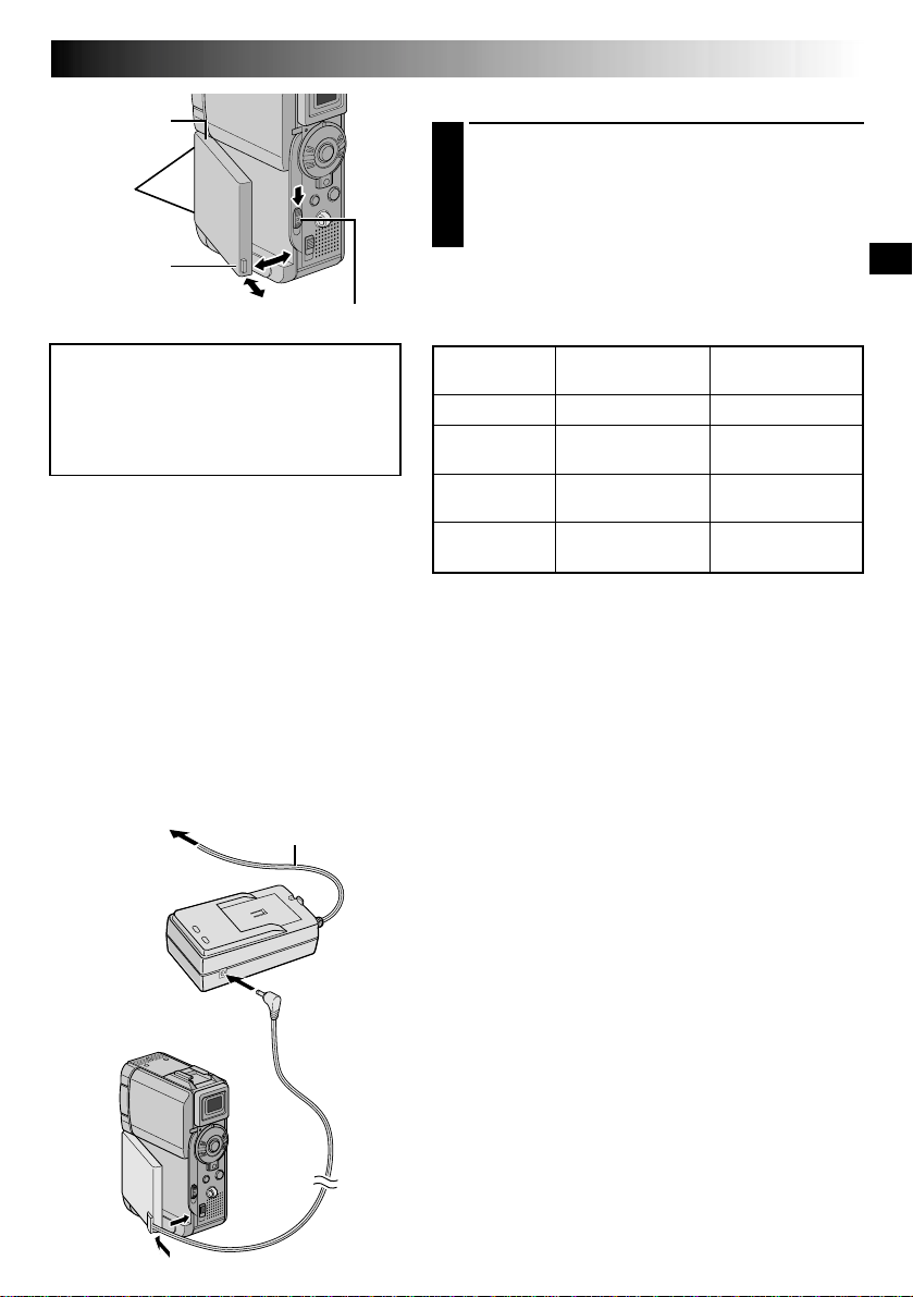
Battery pack
CHARGE
POWER
indicator
BN-V107U
BN-V114U (optional)
NOTES:
●
If the protective cap is attached to the battery pack, remove it first.
●
If you connect the camcorder’s DC cord to the adapter during battery charging, power is supplied to the
camcorder and charging stops.
●
When charging the battery pack for the first time or after a long storage period, the CHARGE indicator may
not light. In this case, remove the battery pack from the AC Power Adapter/Charger, then try charging again.
●
If the battery operation time remains extremely short even after having been fully charged, the battery is
worn out and needs to be replaced. Please purchase a new one.
indicator
DC OUT connector
Battery pack
Protruding part
To
AC outlet
AC Power
Adapter/Charger
Charging time
approx. 1 hr. 30 min.
approx. 2 hr.
Power
This camcorder’s 2-way power supply system lets you
choose the most appropriate source of power. Do not use
provided power supply units with other equipment.
CHARGING THE BATTERY PACK
1
2
3
GETTING STARTED
Make sure you unplug the camcorder’s DC cord from
the AC Power Adapter/Charger. Plug the AC Adapter/
Charger’s power cord into an AC outlet. The POWER
indicator lights.
Attach the battery pack with the
with the corresponding marks on the AC Power
Adapter/Charger. The CHARGE Indicator begins
blinking to indicate charging has started.
When the CHARGE indicator stops blinking but stays
lit, charging is finished. Remove the battery by
pushing up the protruding part. Remember to unplug
the AC Adapter/Charger’s power cord from the AC
outlet.
mark aligned
(cont.)
Lithium-ion is vulnerable in colder
temperatures.
About Batteries
DANGER! Do not attempt to take the batteries apart, or
expose them to flame or excessive heat, as it may cause a fire
or explosion.
WARNING! Do not allow the battery or its terminals to come
in contact with metals, as this can result in a short circuit and
possibly start a fire.
The Benefits Of Lithium-Ion Batteries
Lithium-ion battery packs are small but have a large power
capacity. However, when one is exposed to cold temperatures
(below 10°C/50°F), its usage time becomes shorter and it may
cease to function. If this happens, place the battery pack in
your pocket or other warm, protected place for a short time,
then re-attach it to the camcorder. As long as the battery pack
itself is not cold, it should not affect performance.
(If you’re using a heating pad, make sure the battery pack does
not come in direct contact with it.)
For other notes, 墌 pg. 77
1
Notches
2
BATT. RELEASE Switch
ATTENTION:
Before detaching the power source,
make sure that the camcorder’s power
is turned off. Failure to do so can result
in a camcorder malfunction.
INFORMATION:
The extended-use battery pack kit is a set
composed of a battery pack and AC Power
Adapter/Charger:
VU-V840 KIT: BN-V840U battery pack & AAV15U AC Power Adapter/Charger
VU-V856 KIT: BN-V856U battery pack & AAV80U AC Power Adapter/Charger
Read the kit's instruction manual before using.
Neither BN-V840U nor BN-V856U can be
charged by using the AC Adapter provided
with this camcorder. Use only the AA-V15U
AC Power Adapter/Charger for BN-V840U
battery pack and only AA-V80U AC Power
Adapter/Charger for BN-V856U battery pack.
To AC outlet
AC Power
Adapter/Charger
Power cord
To DC OUT
terminal
EN11
USING THE BATTERY PACK
Insert the terminal end 1 of the battery pack into the
1
battery pack mount, then firmly push the end 2 of
the battery pack in the direction of the arrow until it
locks into place as shown in the illustration.
•To attach the battery firmly, align its two notches
with the tabs on the camcorder.
To Detach The Battery Pack. . .
.... while sliding down BATT. RELEASE, detach it.
Approximate recording time
Battery pack
BN-V107U
BN-V114U
(optional)
BN-V840U
(optional)
BN-V856U
(optional)
NOTES:
●
Recording time is reduced significantly under the
following conditions:
•
Zoom or Record-Standby mode is engaged repeatedly.
•
The LCD monitor is used repeatedly.
•
The playback mode is engaged repeatedly.
●
Before extended use, it is recommended that you
prepare enough battery packs to cover 3 times the
planned shooting time.
LCD monitor on/
Viewfinder off
1 hr.
2 hr.
5 hr. 10 min.
7 hr. 40 min.
LCD monitor off/
Viewfinder on
1 hr. 10min.
2 hr. 20 min.
6 hr. 20 min.
9 hr. 20 min.
USING AC POWER
Use the AC Power Adapter/Charger (connect as shown in
the illustration).
NOTES:
●
The provided AC Power Adapter/Charger features
automatic voltage selection in the AC range from 110 V
to 240 V.
●
For other notes, 墌 pg. 77.
To battery
pack mount
DC cord
12 EN
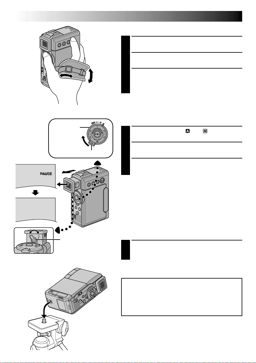
PAUSE
Power
Switch
Lock Button
GETTING STARTED
Grip Adjustment
Loosen the belt.
1
Pass your right hand through the loop and grasp the
2
grip.
Adjust your thumb and fingers through the grip, to
3
easily operate the Recording Start/Stop button and
Power Switch and Power Zoom (SHUTTLE SEARCH)
Ring. Be sure to tighten the belt to your preference.
Viewfinder Adjustment
Set the Power Switch to “ ” or “ ” while pressing
1
down the Lock Button located on the switch.
Pull out the viewfinder fully.
2
Turn the Diopter Adjustment Control until the
3
indications in the viewfinder are clearly focused.
(cont.)
Diopter Adjustment
Control
Tripod Mounting
Align the screw on the tripod with the camera’s
1
mounting socket. Then tighten the screw.
•Some tripods are not equipped with studs.
CAUTION:
When attaching the camera to a tripod, extend its
legs to stabilize the camcorder. It is not advised to use
small sized tripods. This may cause damage to the
unit by falling over.

SET/SELECT Button
Power lamp
Power Switch
Lock Button
MENU Button
+, – Button
EN13
Date/Time Settings
The date/time is recorded onto the tape at all times, but its
display can be turned on or off during playback
(墌 pg. 44, 45).
Set the Power Switch to “ ” while pressing down
1
the Lock Button located on the switch, then open
the LCD monitor fully or pull out the viewfinder
fully. The power lamp lights and the camcorder is
turned on.
Press MENU. The Menu Screen appears.
2
Press + or – to select “ DISPLAY”, and press SET/
3
SELECT. The DISPLAY Menu appears.
/ W I P E
W. BAL
MSYSTE
DSC
END
T I ME COD E
CLOCK
ADJ .
CLOCK
ADJ .
Display
FADER
AM A EPROGR
AN E
C
ACAMER
LMANUA
AYDISPL
RE NEON SC
IMETDA TE /
NRETUR
OF
–
–
– FFO
F
LCD/ T V
UAOT
25 ’01
CED
30PM:5
25 ’01
CED
30PM:5
DISPLAY Menu
Press + or – to select “CLOCK ADJ.”, and press SET/
4
SELECT. “Month” is highlighted.
Press + or – to input the month, and press SET/
SELECT. Repeat to input the day, year, hour and
minute. Press + or – to select “ RETURN”, and
press SET/SELECT twice. The Menu Screen closes.
Built-in Clock’s Rechargeable Lithium Battery
To store the date/time in memory, the clock’s rechargeable
lithium battery is integrated in the camcorder. While the
camcorder is connected to an AC outlet using the AC
Power Adapter/Charger, or while the battery pack attached
to the camcorder continues to supply power, the clock’s
rechargeable lithium battery is always charged. However,
if the camcorder is not used for approx. 3 months, the
clock’s lithium battery will become discharged and the
date/time stored in memory will be lost. When this occurs,
first connect the camcorder to an AC outlet using the AC
Power Adapter/Charger for over 24 hours to charge the
clock’s rechargeable lithium battery. Then perform the
date/time setting before using the camcorder.
Note that the camcorder can be used without setting the
date/time.
NOTE:
Even if you select “CLOCK ADJ.”, if the parameter is not
highlighted the camcorder’s internal clock continues to
operate. Once you move the highlight bar to the first
date/time parameter (month), the clock stops. When you
finish setting the minute and press SET/SELECT, the date
and time begin operation from the date and time you
have just set.
14 EN
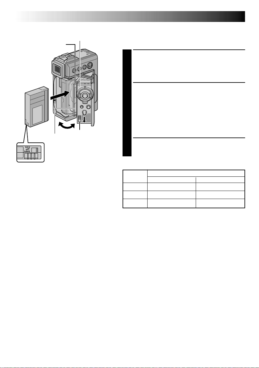
Cassette holder cover
Cassette holder
Make sure the
window side is
facing out.
PUSH HERE
Erase protection tab*
*
To Protect Valuable Recordings . . .
....slide the erase protection tab on the back
of the tape in the direction of “SAVE”. This
prevents the tape from being recorded
over. To record on this tape, slide the tab
back to “REC” before loading it.
Be sure to press only the section labeled
“PUSH HERE” to close the cassette holder;
touching other parts may cause your finger to
get caught in the cassette holder, resulting in
injury or product damage.
OPEN/EJECT
Switch
GETTING STARTED
(cont.)
Loading/Unloading A Cassette
The camcorder needs to be powered up to load or eject a
cassette.
Slide down and hold OPEN/EJECT in the direction
1
of the arrow then pull the cassette holder cover
open until it locks. The cassette holder opens
automatically.
•Do not touch internal components.
Insert or remove a tape and press “PUSH HERE” to
2
close the cassette holder.
•Once the cassette holder is closed, it recedes
automatically. Wait until it recedes completely
before closing the cassette holder cover.
•When the battery’s charge is low, you may not be
able to close the cassette holder cover. Do not
apply force. Replace the battery with a fully
charged one before continuing.
Close the cassette holder cover firmly until it locks
3
into place.
Approximate recording time
Tape
30 min. 30 min. 45 min.
60 min. 60 min. 90 min.
80 min. 80 min. 120 min.
Recording mode
SP LP
NOTES:
●
It takes a few seconds for the cassette holder to open. Do not apply force.
●
If you wait a few seconds and the cassette holder does not open, close the cassette holder cover and try
again. If the cassette holder still does not open, turn the camcorder off then on again.
●
If the tape does not load properly, open the cassette holder cover fully and remove the cassette. A few
minutes later, insert it again.
●
When the camcorder is suddenly moved from a cold place to a warm environment, wait a short time
before opening the cassette holder cover.
●
Closing the cassette holder cover before the cassette holder comes out may cause damage to the
camcorder.
●
Even when the camcorder is switched off, a cassette can be loaded or unloaded. After the cassette holder
is closed with the camcorder switched off, however, it may not recede. It is recommended to turn the
power on before loading or unloading.
●
When resuming recording, once you open the cassette holder cover a blank portion will be recorded on
the tape or a previously recorded scene will be erased (recorded over) regardless of whether the cassette
holder came out or not. See page 22 for information about recording from the middle of a tape.

SET/SELECT Button
Power lamp
Power Switch
MENU Button
+, – Button
Recording Mode Setting
Set the tape recording mode depending on your
preference.
Set the Power Switch to “ ” while pressing down
1
the Lock Button located on the switch, then open
the LCD monitor fully or pull out the viewfinder
fully. The power lamp lights and the camcorder is
turned on.
Press MENU. The Menu Screen appears.
2
EN15
Lock Button
Display
REC MODE – SP
LP
CAMERA Menu
Sub Menu
Press + or – to select “ CAMERA” and press SET/
3
SELECT. The CAMERA Menu appears.
Press + or – to select “REC MODE” and press SET/
4
SELECT. The Sub Menu appears. Select “SP” or “LP”
by pressing + or – and press SET/SELECT. Press + or
– to select “ RETURN”, and press SET/SELECT
twice. The Menu Screen closes.
•Audio Dubbing (墌 pg. 66) and Insert Editing
(墌 pg. 68) are impossible on a tape recorded in
the LP mode.
•“LP” (Long Play) is more economical, providing
1.5 times the recording time.
NOTES:
●
If the recording mode is switched during recording, the
playback picture will be blurred at the switching point.
●
It is recommended that tapes recorded in the LP mode
on this camcorder be played back on this camcorder.
●
During playback of a tape recorded on another
camcorder, blocks of noise may appear or there may
be momentary pauses in the sound.

16 EN
GETTING STARTED
(cont.)
Loading A Memory Card
The provided memory card is already inserted in the
camcorder when you receive the camcorder.
Make sure the camcorder’s power is off.
1
Open the card cover (MEMORY CARD).
2
Card Cover
Clipped edge
Memory card
Label
To Protect Valuable Files (available
only for SD Memory Card) . . .
Insert the memory card firmly clipped edge first.
3
•Do not touch the terminal on the reverse side of
the label.
Close the card cover.
4
To Unload A Memory Card . . .
.... in step 3 push the memory card, then the memory
card comes out of the camcorder automatically. Pull
it out and close the card cover.
NOTES:
●
Be sure to use only SD Memory Cards marked “ ”
or MultiMediaCards marked “ ”.
●
Some brands of memory cards are not compatible with
this camcorder. Before purchasing a memory card,
consult its manufacturer or dealer.
●
Before using a new memory card, it is necessary to
FORMAT the card. 墌 pg. 38
ATTENTION:
Do not insert/remove the memory card while the
camcorder is turned on, as this may cause the
memory card to be corrupted or cause the camcorder
to become unable to recognize whether or not the
card is installed.
Erase protection
tab
... slide the erase protection tab on the side
of the memory card in the direction of
“LOCK”. This prevents the memory card
from being recorded over. To record on
this memory card, slide the tab back to
the position opposite to “LOCK” before
loading it.
SET/SELECT Button
Power Switch
Lock Button
Display
– FINE
TYQUAL I
SIZE
UXGA
STANDARD
–
AUTO
–
–
VGA
SIZEIMAGE
XGA
AUTO–
GAV
MENU Button
+, – Button
DSC Menu
EN17
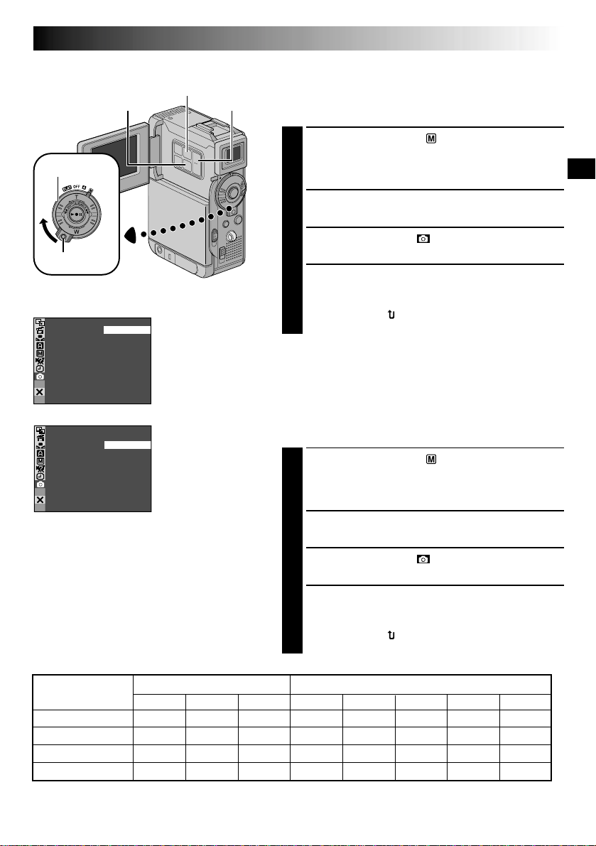
Picture Quality Mode Setting
The Picture Quality mode can be selected to best match
your needs. Two Picture Quality modes are available:
FINE and STANDARD (in order of quality).
Set the Power Switch to “ ” while pressing down the
1
Lock Button located on the switch, then open the LCD
monitor fully or pull out the viewfinder fully. The
power lamp lights and the camcorder is turned on.
Press MENU. The Menu Screen appears.
2
Press + or – to select “ DSC” and press SET/
3
SELECT. The DSC Menu appears.
Press + or – to select “QUALITY” and press SET/
4
SELECT. The Sub Menu appears. Press + or – to
select the desired mode and press SET/SELECT. Press
+ or – to select “ RETURN”, and press SET/SELECT
twice. The Menu Screen closes.
Image Size Mode Setting
The Image Size mode can be selected to best match your
needs. Two Image Size modes are available: XGA (1024 x
768 pixels) and VGA (640 x 480 pixels) (in order of
quality).
Set the Power Switch to “ ” while pressing down the
1
Lock Button located on the switch, then open the LCD
monitor fully or pull out the viewfinder fully. The
power lamp lights and the camcorder is turned on.
NOTES:
●
The number of storable images depends on
the selected picture quality as well as the
composition of the subjects in the images
and the type of memory card being used.
●
In the XGA mode, images are shot in 720 x
480 pixels and they are converted and
stored in the XGA mode file size (1024 x
768 pixels).
Approximate Number of Storable Images
Image Size/Picture
Quality Mode
XGA FINE 24 49 100 16 20 46 97 195
XGA STANDARD 74 150 305 51 62 140 295 610
VGA FINE 53 105 215 37 44 100 210 435
VGA STANDARD 150 310 630 105 125 290 610 1255
* Optional
** Provided (12 sound effects pre-stored)
MultiMediaCard SD Memory Card
8MB*
16MB*
32MB* 8MB**
Press MENU. The Menu Screen appears.
2
Press + or – to select “ DSC” and press SET/
3
SELECT. The DSC Menu appears.
Press + or – to select “IMAGE SIZE” and press SET/
4
SELECT. The Sub Menu appears. Press + or – to
select the desired mode and press SET/SELECT. Press
+ or – to select “ RETURN”, and press SET/SELECT
twice. The Menu Screen closes.
8MB* 32MB* 64MB*
16MB*
18 EN
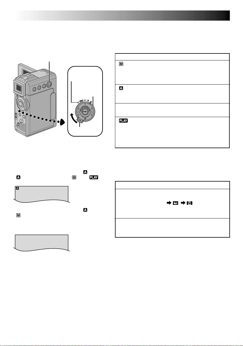
To turn on the camcorder, set the Power
Switch to any operation mode except “OFF”
while pressing down the Lock Button located
on the switch.
VIDEO/MEMORY
Switch
Power lamp
Power Switch
Lock Button
When the Power Switch is set to “ ”,
“ ” appears. When set to “ ” or “ ”,
there is no indication.
When the Power Switch is set to “ ” or
“ ” and the VIDEO/MEMORY Switch is set
to “MEMORY”, the selected image size
(“VGA” or “XGA”) is displayed. When set to
“VIDEO”, there is no indication.
VGA
GETTING STARTED
(cont.)
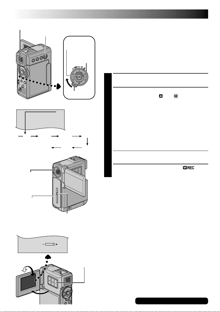
Operation Mode
Choose the appropriate operation mode according to
your preference using the Power Switch and VIDEO/
MEMORY Switch.
Power Switch Position
(Manual):
Allows you to set various recording functions using
the Menus. If you want more creative capabilities than
Full Auto recording, try this mode.
(Full Auto):
Allows you to record using NO special effects or
manual adjustments. Suitable for standard recording.
OFF:
Allows you to switch off the camcorder.
:
•Allows you to play back a recording on the tape.
•Allows you to display a still image stored in the
memory card or to transfer a still image stored in the
memory card to a computer.
VIDEO/MEMORY Switch Position
VIDEO:
Allows you to record on a tape or play back a tape. If
“REC SELECT” is set to “ / ” in the DSC
Menu Screen, still images are also recorded in the
memory card.
MEMORY:
Allows you to record a still image or display a still
image stored in the memory card.

VIDEO RECORDING & PLAYBACK
VIDEO RECORDING
&
PLAYBACK
CONTENTS
EN19
VIDEO RECORDING
Basic Recording
Journalistic Shooting
Interface Shooting
Zooming
Time Code
Recording From The Middle Of A Tape .......................................
...................................................................... 21
VIDEO PLAYBACK
Normal Playback ........................................................
Still Playback ............................................................
Shuttle Search ...........................................................
Connections
Blank Search
............................................. 20 – 22
.............................................................. 20
........................................................ 21
.......................................................... 21
.................................................................... 22
............................................... 23 – 26
.......................................................... 24 – 25
................................................................. 26
22
23
23
23
20 EN
BR I GHT
25
min
Power Lamp
VIDEO/MEMORY
Switch
Recording Start/
Stop Button
Power Switch
VIDEO RECORDING
Basic Recording
NOTE:
You should already have performed the procedures listed
below. If not, do so before continuing.
●
Power (墌 pg. 10)
●
Grip Adjustment (墌 pg. 12)
●
Viewfinder Adjustment (墌 pg. 12)
●
Load A Cassette (墌 pg. 14)
●
Recording Mode Setting (墌 pg. 15)
Slide down the lens cover while pressing down the
1
Lock Button located on the cover.
Display
min
(Now calculating)
Tally lamp (Lights
while recording is
in progress)
Lens Cover (Slide up
the lens cover to
protect the lens
when the camcorder
is not in use.)
180°
90 min
(Blinking) (Blinking) (Blinking)
90°
Lock Button
Tape remaining
time indicator
(Approximate)
89 min
1 min0 min
Lock Button
MONITOR BRIGHT
+/– Button
3 min
2 min
Set the VIDEO/MEMORY Switch to “VIDEO”, then
2
set the Power Switch to “ ” or “ ” while pressing
down the Lock Button located on the switch.
Shooting while using the LCD monitor:
the viewfinder is pushed back in. Open the LCD
monitor fully.
Shooting while using the viewfinder:
LCD monitor is closed and locked. Pull out the
viewfinder fully.
•Be sure to pull out the viewfinder until you hear a
click, otherwise it may be pushed back in during
use.
•The Power lamp lights and the camcorder enters the
Record-Standby mode. “PAUSE” is displayed.
Press the Recording Start/Stop Button. “ ”
3
appears while recording is in progress.
To Stop Recording . . .
.... press the Recording Start/Stop Button. The camcorder
re-enters the Record-Standby mode.
To Adjust The Brightness Of The Display
.... press MONITOR BRIGHT + or – until the bright level
indicator on the display moves and the appropriate
brightness is reached.
•It is also possible to adjust the brightness of the viewfinder.
NOTES:
●
The image will not appear simultaneously on the LCD
monitor and the viewfinder except during Interface
Shooting.
●
If the Record-Standby mode continues for 5 minutes, the
camcorder’s power shuts off automatically. To turn the
camcorder on again, push back and pull out the
viewfinder again or close and re-open the LCD monitor.
●
When a blank portion is left between recorded scenes
on the tape, the time code is interrupted and errors
may occur when editing the tape. To avoid this, refer to
“Recording From The Middle Of A Tape” (墌 pg. 22).
●
When sliding down the lens cover, be sure not to touch
the lens.
●
To turn the tally lamp or beep sounds off, 墌 pg. 40, 42.
Make sure
Make sure the
For other notes, 墌 pg. 77

Self-Recording
EN21
Journalistic Shooting
In some situations, different shooting angles may provide more dramatic
results. Hold the camcorder in the desired position and tilt the LCD
monitor in the most convenient direction. It can rotate 270° (90° downward, 180° upward).
Interface Shooting
The person you shoot can view himself/herself in the LCD monitor, and
you can even shoot yourself while viewing your own image in the LCD
monitor.
Open the LCD monitor and tilt it upward to 180° so that it faces forward.
When the LCD monitor is tilted upward to an angle of over approx. 105°,
the monitor image is inverted vertically. If the viewfinder is pulled out at
that time, it also switches on.
Point the lens toward the subject (yourself when self-recording) and start
recording.
During Interface Shooting, the monitor image and indications do not
appear inverted as they would when viewing a mirror.
Zoom in (T: Telephoto)
1xW
T
10xW
T
Zoom out (W: Wide angle)
Zoom display
10xW
Approximate zoom ratio
T
20xW
T
Power Zoom
Ring
40xW
T
Digital zoom zone
10X (optical) zoom
zone
FEATURE:
Zooming
PURPOSE:
To produce the zoom in/out effect, or an instantaneous
change in image magnification.
OPERATION:
Zoom In
Turn the Power Zoom (SHUTTLE SEARCH) Ring
towards “T”.
Zoom Out
Turn the Power Zoom (SHUTTLE SEARCH) Ring
towards “W”.
䡲 The further you turn the Power Zoom Ring the
quicker the zoom action.
NOTES:
●
Focusing may become unstable during Zooming. In
this case, set the zoom while in Record-Standby,
lock the focus by using the manual focus
(墌 pg. 53), then zoom in or out in Record mode.
●
Zooming is possible to a maximum of 200X, or it
can be switched to 10X magnification using the
optical zoom (墌 pg. 41).
●
Zoom magnification of over 10X is done through
Digital image processing, and is therefore called
Digital Zoom.
●
During Digital zoom, the quality of image may
suffer.
●
Digital zoom cannot be used in the following cases:
•
When digital image processing, such as Picture
Wipe/Dissolve (墌 pg. 50, 51) or Video Echo
(墌 pg. 49), is activated.
●
Macro shooting (as close as approx. 5 cm (2") to the
subject) is possible when the Power Zoom Ring is
set all the way to “W”. Also see “TELE MACRO” in
the Menu Screen on page 41.
For other notes, 墌 pg. 77
22 EN
VIDEO RECORDING
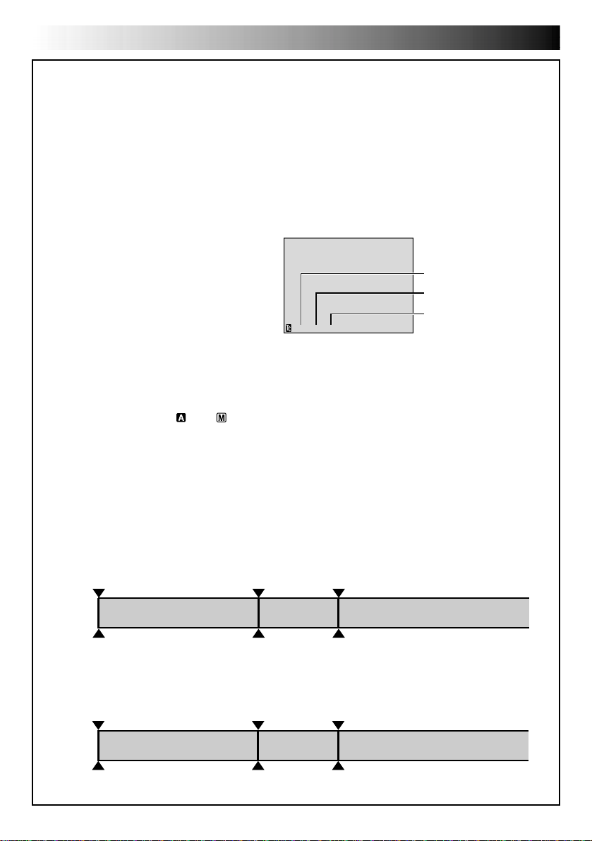
Time Code
During recording, a time code is recorded on the tape. This code is to confirm the location of the recorded
scene on the tape during playback.
If recording starts from a blank portion, the time code begins counting from “00:00:00”
(minute:second:frame). If recording starts from the end of a previously recorded scene, the time code
continues from the last time code number.
To perform Random Assemble Editing (墌 pg. 69 – 73), time code is necessary. If during recording a blank
portion is left partway through the tape, the time code is interrupted. When recording is resumed, the time
code starts counting up again from “00:00:00”. This means the camcorder may record the same time
codes as those existing in a previously recorded scene. To prevent this, perform “Recording From The
Middle of A Tape” below in the following cases;
•When shooting again after playing back a
recorded tape.
•When power shuts off during shooting.
•When a tape is removed and re-inserted during
shooting.
•When shooting using a partially recorded tape.
•When shooting on a blank portion located
partway through the tape.
•When shooting again after shooting a scene
then opening/closing the cassette holder cover.
12:34:24
Display
Frames are not displayed
during recording.
Minutes
Seconds
Frames
(30 frames = 1 second)
Recording From The Middle Of A Tape
1. Play back a tape or use Blank Search (墌 pg. 26) to find the spot at which you want to start recording,
then engage the Still Playback mode (墌 pg. 23).
2. Set the Power Switch to “ ” or “ ” while pressing down the Lock Button located on the switch, then
start recording.
NOTES:
●
The time code cannot be reset.
●
During fast-forwarding and rewinding, the time code indication does not move smoothly.
●
The time code is displayed only when “TIME CODE” is set to “ON” (墌 pg. 43, 44).
(cont.)
When a blank portion is recorded on a tape
Time code
00:00:00
Tape
Shooting start point
Time code
05:43:21
Proper recording
Time code
00:00:00
Tape
Shooting start point
Time code
05:43:21
Time code
00:00:00
Shooting start pointShooting stop point
Time code
05:44:00
Shooting start pointShooting start point
Newly recorded sceneBlankAlready recorded scene
Latest sceneNew sceneAlready recorded scene

VIDEO PLAYBACK
VOL. +/–
VIDEO/MEMORY
Switch
Play/Pause
Button (4/6)
Lock Button
Speaker
Stop Button (5)
SHUTTLE SEARCH
Ring (2/3)
Power Switch
EN23
Normal Playback
Load a tape ( pg. 14).
1
Set the VIDEO/MEMORY Switch to “VIDEO”, then
2
set the Power Switch to “ ” while pressing down
the Lock Button located on the switch. To start
playback, press 4/6.
•To stop playback, press 5.
•Turn the SHUTTLE SEARCH Ring to the left (2)
to rewind, or to the right (3) to fast-forward the
tape during Stop mode.
To Control The Speaker Volume . . .
.... press VOL. + to turn up the volume, or – to turn
down the volume.
NOTES:
●
If Stop mode continues for 5 minutes when power is supplied
from a battery, the camcorder shuts off automatically. To turn
on again, set the Power Switch to “OFF”, then to “ ”.
●
The playback picture can be viewed in the LCD monitor,
viewfinder or on a connected TV ( pg. 24, 25).
●
You can also view the playback picture on the LCD monitor
with it flipped over and pushed against the camera body.
●
LCD monitor/viewfinder indications:
•
When power is supplied from a battery: the “ ”
battery pack remaining power indicator is displayed.
When power is supplied from an AC outlet: “ ”
does not appear.
•
During Stop mode, none of the indications are displayed.
●
When a cable is connected to the AV connector, the
sound is not heard from the speaker.
Still Playback:
1) Press 4/6 during playback.
2) To resume normal playback, press 4/6 again.
●
If still playback continues for more than about 3 minutes, the camcorder’s Stop mode is automatically
engaged. After 5 minutes in the Stop mode, the camcorder’s power is automatically turned off.
●
When
4/6
Shuttle Search:
1) During playback, turn the SHUTTLE SEARCH Ring to the right (3) for forward or to the left (2)
for reverse search.
2) To resume normal playback, press 4/6.
●
During playback, turn the SHUTTLE SEARCH Ring to the right (3) or to the left (2) and hold it.
The search continues as long as you hold the ring. Once you release it, normal playback resumes.
●
A slight mosaic effect appears on screen during Shuttle Search. This is not a malfunction.
Pauses during playback.
is pressed, the image may not pause immediately while the camcorder stabilises the still image.
Allows high-speed search in either direction.
Slow-Motion Playback, Frame-By-Frame Playback, Playback Zoom and
Playback Special Effects
Available only with the remote control (provided) ( pg. 64, 65).

24 EN
VIDEO PLAYBACK
Connections
These are some basic types of connections. When making the connections, refer also to your VCR and TV
instruction manuals.
A. Connection to a TV or VCR equipped only with A/V input connectors
To TV or VCR
(cont.)
TV
VCR
* The Audio cable is not required for watching still images only.
White to AUDIO L IN*
Yellow to VIDEO IN
Red to
AUDIO R IN*
Audio/Video cable
(provided)
To AV OUT
B. Connection to a TV or VCR equipped with an S-VIDEO IN and A/V input connectors
Audio/Video cable
To TV or VCR
White to AUDIO L IN*
TV
VCR
* The Audio cable is not required for watching still images only.
** Refer to “Docking Station Attachment” ( pg. 25).
Red to AUDIO R IN*
To S-VIDEO IN
Yellow: Not connected
S-Video cable
(optional)
(provided)
To AV OUT
To S-VIDEO
Docking
Station**
Make sure all units are turned off.
1
Connect the camcorder to a TV or VCR as
2
shown in the illustration ( pg. 24).
If using a VCR . . . go to step 3.
If not . . . go to step 4.
Connect the VCR output to the TV input,
3
referring to your VCR’s instruction manual.
Turn on the camcorder, the VCR and the TV.
4
Set the VCR to its AUX input mode, and set the
5
TV to its VIDEO mode.
To choose whether or not the following displays
appear on the connected TV . . .
•Date/Time
.... set “DATE/TIME” to “AUTO”, “ON” or “OFF”
in the Menu Screen ( pg. 44, 45).
•Time Code
.... set “TIME CODE” to “ON” or “OFF” in the
Menu Screen ( pg. 44, 45).
•Playback Sound Mode, Tape Speed And Tape
Running Displays for video playback
Or
Type of file, Directory/File Names and Image
Number/Total Number of Images for D.S.C.
Playback
.... set “ON SCREEN” to “LCD” or “LCD/TV” in
the Menu Screen ( pg. 44, 45).
Or, press DISPLAY on the remote control.
EN25
NOTES:
●
It is recommended to use the AC Power Adapter/
Charger as the power supply instead of the
battery pack ( pg. 11).
●
The S-Video cable is optional. Be sure to use the
YTU94146B S-Video cable.
Consult the JVC Service Center described on the
sheet included in the package for details on its
availability. Make sure to connect the end with a
core filter to the camcorder. The core filter
reduces interference.
●
To monitor the picture and sound from the
camcorder without inserting a tape or memory
card, set the camcorder’s Power Switch to “ ”
or “ ”, then set your TV to the appropriate input
mode.
●
Make sure you adjust the TV sound volume to its
minimum level to avoid a sudden burst of sound
when the camcorder is turned on.
●
If you have a TV or speakers that are not specially
shielded, do not place the speakers adjacent to
the TV as interference will occur in the camcorder
playback picture.
●
While the Audio/Video cable is connected to the
AV connector, sound cannot be heard from the
speaker.
Docking Station Attachment
First align the multi connector and screw on the
Docking Station with the camcorder’s multi
connector and tripod mounting socket and tighten
the screw.
When removing the camcorder, loosen the screw
and detach the camcorder.
NOTE:
While the Docking Station is attached to the
camcorder, it is not possible to load and unload
the memory card. Also, connecting and disconnecting the DV cable are not possible.
Multi connector
Screw
Tripod mouting
socket

26 EN
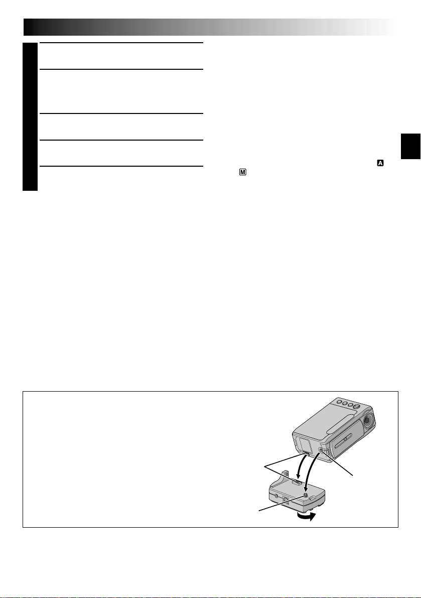
FOCUS/BLANK Button
Stop Button (5)
Display
BLANK S EARCH
VIDEO/MEMORY Switch
Power Switch
Lock Button
44
VIDEO PLAYBACK
(cont.)
Blank Search
Helps you find where you should start recording in the
middle of a tape to avoid time code interruption
( pg. 22).
Load a tape ( pg. 14).
1
Set the VIDEO/MEMORY Switch to “VIDEO”, then
2
set the Power Switch to “ ” while pressing down
the Lock Button located on the switch.
Press FOCUS/BLANK.
3
•“BLANK SEARCH” appears blinking and the
camcorder automatically starts reverse or forward
shuttle search, then stops at the spot which is
about 3 seconds of tape before the beginning of
the detected blank portion.
To cancel Blank Search midway . . .
.... press 5.
NOTES:
●
In step 3, if the current position is at a blank portion the
camcorder searches in the reverse direction, and if the
current position is at a recorded portion the camcorder
searches in the forward direction.
●
Blank Search does not work if “HEAD CLEANING
REQUIRED. USE CLEANING CASSETTE” has appeared
with the tape.
●
If the beginning or end of the tape is reached during
Blank Search, the camcorder stops automatically.
●
A blank portion which is shorter than 5 seconds of tape
may not be detected.
●
The detected blank portion may be located between
recorded scenes. Before you start recording, make sure
there is no recorded scene after the blank portion.

DIGITAL STILL CAMERA (D.S.C.) RECORDING & PLAYBACK
DIGITAL STILL CAMERA (D.S.C.)
RECORDING
&
PLAYBACK
CONTENTS
EN27
D.S.C. RECORDING
Basic Shooting (Snapshot)
D.S.C. PLAYBACK
Normal Playback (Of Images) ...................................................
Auto Playback (Of Images) ......................................................
Index Screen
Index Playback
Jump Playback
Protecting Files
Deleting Files
Setting Print Information (DPOF Setting)
Initializing A Memory Card
.............................................. 28 – 29
......................................... 28 – 29
................................................ 30 – 38
................................................................. 31
.............................................................. 32
............................................................... 32
.............................................................. 33
......................................................... 34 – 35
....................... 36 – 37
................................................ 38
30
30
28 EN
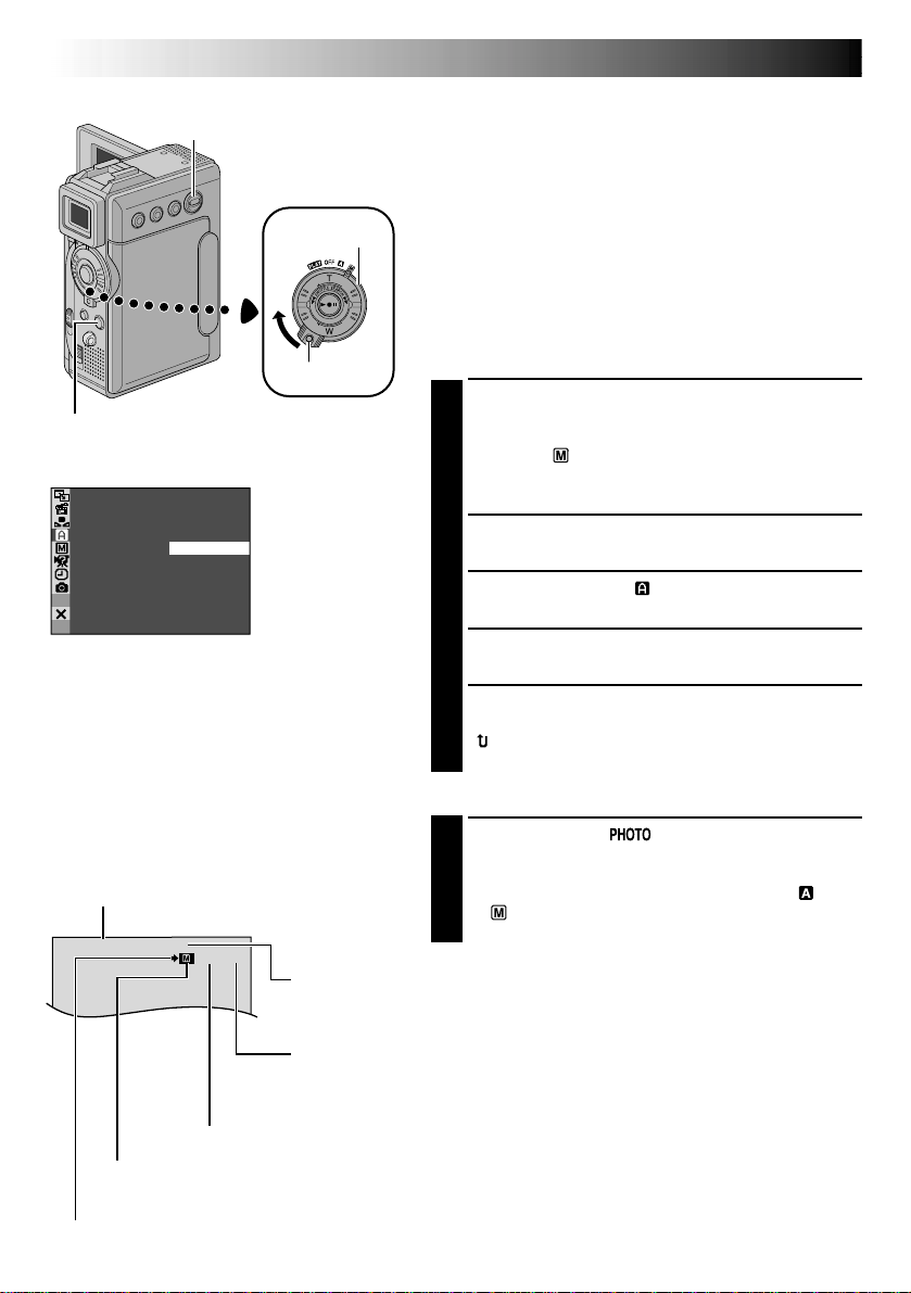
FINE
10 / 100
SNAPSHOT Button
Display
VIDEO/MEMORY
Switch
Power Switch
CAMERA Menu
Lock Button
D.S.C. RECORDING
Basic Shooting (Snapshot)
You can use your camcorder as a Digital Still Camera for
taking snapshots.
NOTE:
You should already have performed the procedures listed
below. If not, do so before continuing.
●
Power ( pg. 10)
●
Grip Adjustment ( pg. 12)
●
Viewfinder Adjustment ( pg. 12)
●
Loading A Memory Card ( pg. 16)
●
Picture Quality/Image Size Mode Setting ( pg. 17)
SNAPSHOT MODE SELECTION
Slide down the lens cover while pressing down the
1
Lock Button located on the cover. Set the VIDEO/
MEMORY Switch to “MEMORY”, then set the Power
Switch to “ ” while pressing down the Lock Button
located on the switch. Open the LCD monitor fully
or pull out the viewfinder fully.
SNAP MODE –
PIN–UP
FRAME
FULL
MUL T I –
MUL T I –
4
9
Press MENU. The Menu Screen appears.
2
Press + or – to select “ CAMERA”, then press SET/
3
SELECT. The CAMERA Menu appears.
Press + or – to select “SNAP MODE”, then press
4
SET/SELECT.
Press + or – to select the desired Snapshot mode,
5
then press SET/SELECT. Press + or – to select
“ RETURN” and press SET/SELECT twice. The
Menu Screen closes.
SNAPSHOT RECORDING
Image Size mode
Displays the Image Size mode of the stored
image. There are 2 modes available: XGA and
VGA ( pg. 17).
Display
VGA
Picture Quality mode
Displays the Picture Quality mode of the stored image. There are 2 modes
available: FINE and STD (Standard) ( pg. 17).
Total number of shots
Displays the approximate total number of shots that can be stored, including
those already taken. The number increases or decreases depending on the shots
stored, the Picture Quality/Image Size mode, etc.
Number of shots taken
Card icon
Appears during shooting and blinks when a memory card is not loaded.
Shooting icon
Appears and blinks during shooting.
Displays the number of images that have already been shot.
Press SNAPSHOT. appears while the snapshot
1
is being taken.
The image is stored in the memory card.
•Regardless of the Power Switch position (“ ” or
“ ”), Snapshot recording takes place using the
selected Snapshot mode.

PIN-UP
Pin-Up mode*
FRAME
Snapshot mode
with frame*
FULL
Snapshot mode
with no frame*
MULTI-4
Multi-Analyzer 4
MULTI-9
Multi-Analyzer 9
EN29
To Delete Unwanted Still Images . . .
.... when unwanted still images are stored in the
memory card or its memory is full, refer to “Deleting
Files” ( pg. 34) and delete unwanted still images.
To Remove The Shutter Sound . . .
.... when you do not want to hear the shutter sound, set
“BEEP” to “OFF” in the Menu Screen ( pg. 40, 42).
The sound is no longer heard from the speaker.
NOTES:
●
Even if “MULTI-4” or “MULTI-9” is engaged, Snapshot
recording will be performed in the FULL mode during
Digital Zoom or Night-Alive ( pg. 48).
●
The image is stored in the VGA mode regardless of the
image size mode setting ( pg. 17) if “MULTI-4” or
“MULTI-9” is engaged.
●
If SNAPSHOT is pressed when “DIS” is set to “ON”
(pg. 41), the Stabiliser will be disabled.
●
If Snapshot recording is not possible, “ ” blinks
when SNAPSHOT is pressed.
●
If Program AE with special effects ( pg. 48) is
engaged, certain modes of Program AE with special
effects are disabled during Snapshot recording. In such
a case, the icon blinks.
●
If shooting is not performed for approx. 5 minutes
when the Power Switch is set to “ ” or “ ” and
power is supplied from the battery pack, the camcorder
shuts off automatically to save power. To perform
shooting again, push back and pull out the viewfinder
again or close and re-open the LCD monitor.
●
The Motor Drive mode ( pg. 52) is disabled when the
VIDEO/MEMORY Switch is set to “MEMORY”.
●
When a cable is connected to the AV connector, the
shutter sound is not heard from the speaker, however it
is recorded onto the tape.
●
Still images taken are compliant to DCF (Design rules
for Camera File systems). They do not have any
compatibility with devices which are not compliant to
DCF.
●
In the XGA mode, images are shot in 720 x 480 pixels
and they are converted and stored in the XGA mode
file size (1024 x 768 pixels).
* There is the sound effect of a shutter
closing.
30 EN
10
24
100
0010
100
0011
100
0012
100
0013
JAN
10
01
11
24
JAN
10
01
12
24
JAN
10
01
13
24
JAN
10
01
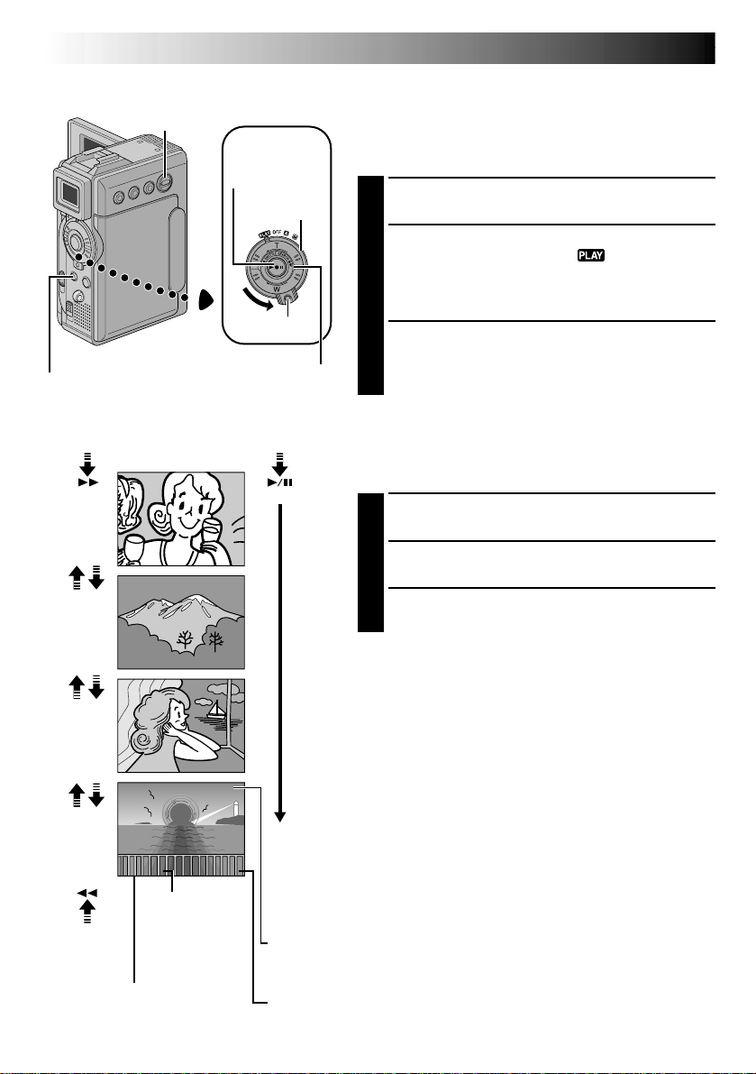
Stop Button (5)
VIDEO/MEMORY
Switch
SHUTTLE SEARCH Ring
(2/3)
Play Button
(4/6)
Power Switch
Lock Button
D.S.C. PLAYBACK
Normal Playback (Of Images)
Images shot with the camcorder are automatically
numbered, then stored in numerical order in the memory
card. You can view the stored images, one at a time,
much like flipping through a photo album.
Load a memory card ( pg. 16).
1
Set the VIDEO/MEMORY Switch to “MEMORY”,
2
then set the Power Switch to “ ” while pressing
down the Lock Button. Open the LCD monitor fully
or pull out the viewfinder fully.
•A stored image is displayed.
Turn the SHUTTLE SEARCH Ring to the right (3)
3
to display the next image.
Turn the SHUTTLE SEARCH Ring to the left (2) to
display the previous image.
[For Normal Playback]
To display the next image
Display
10
/
24
11
12
13
/
24
/
24
/
24
Total number of
To display the
previous image
images
Displays the total
number of stored
images.
Image number
Displays the index
number of the image file
( pg. 31).
[For Auto Playback]
100
-
0010
JAN
10
’01
100
-
0011
JAN
10
’01
100
-
0012
JAN
10
’01
100
-
0013
JAN
10
’01
Auto Playback (Of Images)
You can run through all the images stored in memory
automatically.
Perform steps 1 and 2 above.
1
Press 4/6 to start Auto Playback.
2
To end Auto Playback, press 5.
3
NOTES:
●
Even if you shoot a new image after playing back a
low-numbered one, this will not overwrite an existing
image, because new images are automatically stored
after the last-recorded one.
●
Images shot in a file size other than VGA/XGA with
devices that are compatible with DCF (Design rules for
Camera File systems) will be displayed as reduced-size
thumbnail images. These thumbnail images cannot be
transferred to a PC.
●
Images shot with devices that are not compatible with
DCF cannot be viewed with this camcorder; “Unsup-
ported file!” will be displayed.
Directory and File names
Displays the directory and file
names ( pg. 31).
Date
Displays the date when the image was shot (if “DATE/TIME”is
set to “ON” in the Menu Screen pg. 44–45).
 Loading...