

Page 1
Rev
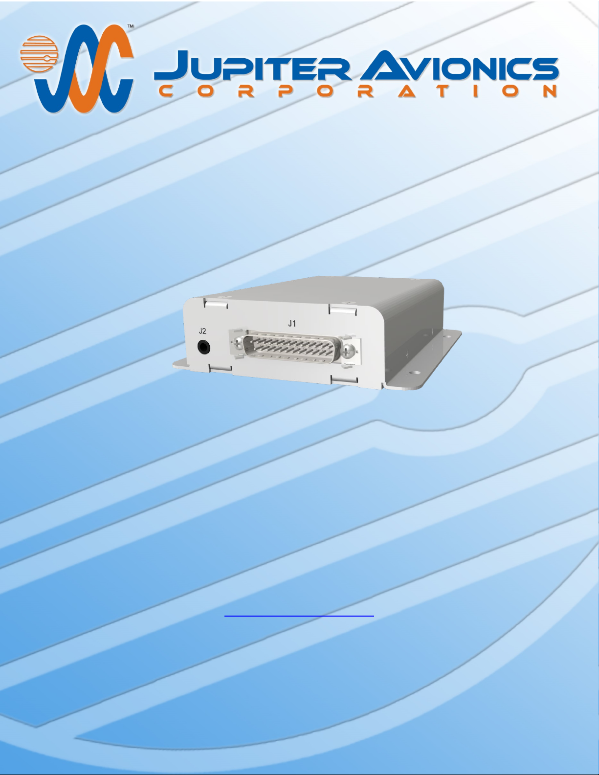
JA35-100 Audio Summing Amplifier –
Remote Mount
Installation and Operating Manual
Rev A
Jupiter Avionics Corporation
1959 Kirschner Road
Kelowna BC
Canada V1Y 4N7
Tel: +1 778 478 2232
Toll-Free: 1 855 478 2232
www.jupiteravionics.com
B Page i
Page 2
JA35-100 Audio Summing Amplifier - Remote Mount
RECORD OF REVISIONS
Revision
Rev Date
Description
ECR
A
Mar 2019
Initial release, Serial number 1001 and higher.
Prepared:
Checked:
Approved:
IMPORTANT:
Installation and Operating Manual
Copyright 2019 Jupiter Avionics Corp.
All rights reserved
Jupiter Avionics Corporation (JAC) permits a single copy of this manual to be printed or downloaded for the express use
of an installing agency. Any such electronic or printed copy of this manual must contain the complete text of this copyright
notice. Any unauthorized commercial distribution of this manual is strictly prohibited. Except as described above, no part
of this manual may be reproduced, copied, transmitted, disseminated, downloaded, or stored in any storage medium for
any purpose without the express prior written consent of JAC.
Information in this document is subject to change without notice.
To confirm the current revision status of this manual, visit the JAC website:
www.jupiteravionics
.com
5285
MP
B
Rev A Page ii
JAC
04-01-19
AH
JAC
04-01-19
KDV
Page 3

JA35-100 Audio Summing Amplifier - Remote Mount
Installation and Operating Manual
Table of Contents
SECTION 1 - DESCRIPTION ................................................................................................................................................. 1
1.1 System Overview .................................................................................................................................................... 1
1.2 Features Overview .................................................................................................................................................. 1
1.3 Inputs and Outputs .................................................................................................................................................. 1
1.3.1 Inputs ............................................................................................................................................................... 1
1.3.2 Outputs ............................................................................................................................................................ 1
1.4 Specifications .......................................................................................................................................................... 1
1.4.1 Electrical Specifications................................................................................................................................... 1
1.4.2 Mechanical Specifications ............................................................................................................................... 2
1.4.3 Product Configuration Software Version ......................................................................................................... 2
SECTION 2 – INSTALLATION ............................................................................................................................................... 3
2.1 Introduction .............................................................................................................................................................. 3
2.2 Continued Airworthiness ......................................................................................................................................... 3
2.3 Unpacking and Inspecting Equipment..................................................................................................................... 3
2.3.1 Warranty .............................................................................................................................................................. 3
2.4 Installation Procedures ............................................................................................................................................ 3
2.4.1 Installation Limitations ......................................................................................................................................... 3
2.4.2 Cabling and Wiring .............................................................................................................................................. 3
2.4.3 Mechanical Installation ........................................................................................................................................ 4
2.4.4 Post Installation Checks ...................................................................................................................................... 4
2.5 Adjustments and Configuration using ProCS™ ...................................................................................................... 4
2.5.1 Configuration Cabling Requirements .............................................................................................................. 4
2.5.2 ProCS™ Setup ................................................................................................................................................ 5
2.5.3 Configurable Settings ...................................................................................................................................... 5
2.5.4 JA35-100 Settings ........................................................................................................................................... 5
2.5.5 Aircraft Audio System List ............................................................................................................................... 8
2.6 Installation Kit .......................................................................................................................................................... 8
2.6.1 Recommended Crimp tools ............................................................................................................................. 8
2.7 Installation Drawings ............................................................................................................................................... 8
SECTION 3 – OPERATION .................................................................................................................................................... 9
3.1 Introduction .............................................................................................................................................................. 9
3.2 Emergency/Normal Mode Operation....................................................................................................................... 9
3.3 System Operation.................................................................................................................................................... 9
3.3.1 Normal Mode of Operation .............................................................................................................................. 9
3.3.2 Emergency Mode Operation ........................................................................................................................... 9
3.3.3 Audio Input Combined Operation .................................................................................................................... 9
3.3.4 Audio Input Split Operation ............................................................................................................................. 9
3.3.5 Audio Input Combined Priority Operation ....................................................................................................... 9
3.3.6 Audio Input Split Priority Operation ................................................................................................................. 9
Appendix A - Installation Drawings ................................................................................................................................... A1
A1 Introduction ............................................................................................................................................................ A1
A2 Installation Drawings ............................................................................................................................................. A1
Appendix B - Installation Documents ............................................................................................................................... B1
B1 Airworthiness Approval ......................................................................................................................................... B2
B2 Instructions for Continued Airworthiness .............................................................................................................. B2
Rev A Page iii
Page 4

JA35-100 Audio Summing Amplifier - Remote Mount
Name
Qty
Type
CONFIG DATA TO JA35-100
1
Data signal
NORM MODE SELECT
1
Multi format signal
POWER INPUT
1
Power supply
INPUT HI/LO
12
Audio signal
Name
Qty
Type
OUTPUT HI/LO
2
Audio signal
CONFIG DATA FROM JA35-100
1
Data signal
SECTION 1 - DESCRIPTION
1.1 System Overview
The JA35-100 audio summing amplifier is a six channel bulkhead mounted isolation audio amplifier with separate
level controls for each channel. It provides two summed output channels with individual level controls, and two
emergency bypass channels for critical audio sources.
The JA35-100 is set up on a per-installation basis using a configuration cable and a PC running the (ProCS) product
configuration tool to download system configuration settings via the configuration connector.
1.2 Features Overview
All JA35-100 internal settings are quickly adjusted using the proprietary ProCS (Product Configuration Software). The
configuration commands set the level of non-volatile digital control potentiometers to control audio signal levels and to
non-volatile expander latches which are connected to audio gates to control the audio signal routing.
The JA35-100 audio summing amplifier provides differential receive audio inputs for high common mode noise
rejection.
The JA35-100 has two modes of operation: Normal Mode and Emergency Mode
1.3 Inputs and Outputs
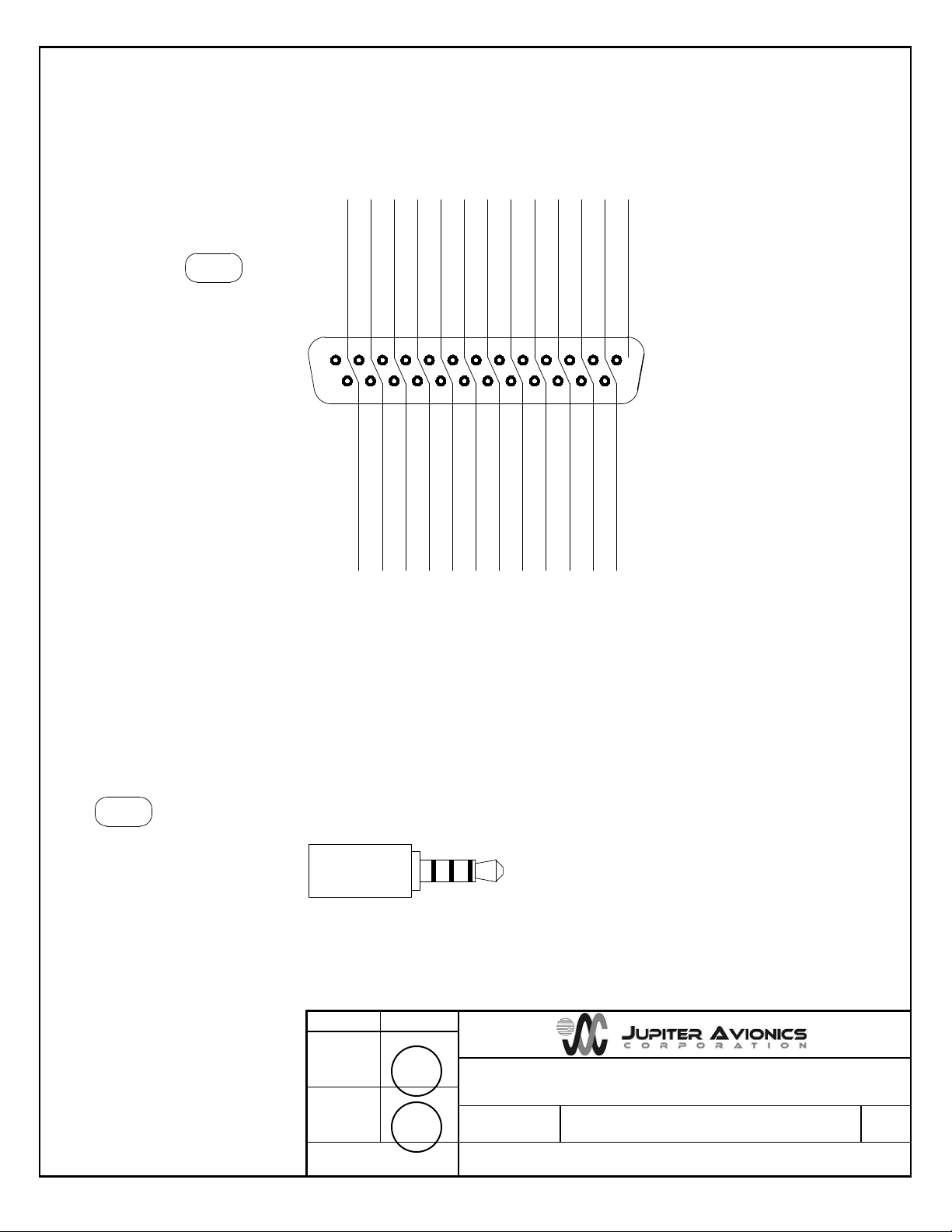
Refer to the JA35-100 connector maps for the mating connector designators and pin assignments for the
input and output signals.
1.3.1 Inputs
1.3.2 Outputs
1.4 Specifications
1.4.1 Electrical Specifications
Power Input
Nominal input voltage 28 Vdc
Maximum voltage 30.3 Vdc
Minimum voltage 22.0 Vdc
Emergency voltage 18.0 Vdc
Maximum current 1 A max
Rev A Page 1
Page 5

JA35-100 Audio Summing Amplifier - Remote Mount
Installation and Operating Manual
1.4.1.1 Audio Performance
Rated Input Level
Audio input rated level 7.75 Vrms ±10%
Rated Output Level
Audio output rated level 7.75 Vrms ±10%
Audio output rated level in EMERG mode 7.75 Vrms ±10%
Audio Frequency Response
Audio output level varies ≤ 3dB from 300 to 6000 Hz
Distortion Characteristics
Audio output distortion at rated power ≤ 10%
Input Impedance
Audio input Impedance 1000 Ω ±10%
Output Load
Rated audio output load 600 Ω
Output Impedance
Phone output Impedance 300 Ω ±10%
Input to Input Crosstalk Level
Input to Input crosstalk ≤ 60 dB
Audio Noise Level without
Signal
Noise level below the rated output ≥ 60 dB
1.4.1.2 Audio Performance, Other
Input circuitry type (Normal) differential
Input circuitry type (Emergency) single ended
Output circuitry type single ended
1.4.2 Mechanical Specifications
Height 1.27 in [32.3 mm] maximum
Depth 4.42 in [112.3 mm] maximum
Width 4.52 in [114.8 mm] maximum
Weight 0.55 lb [0.25 kg] max
Mounting Four 10-32 screws
Material brushed aluminum with conversion
Connectors (2): One 4 pole 3.5mm stereo jack
One 25-pin D-Sub male
Mounting 4 x 10-32 fasteners
Bonding ≤ 2.5 mΩ
Installation kit part number INST-JA35
coating
1.4.3 Product Configuration Software Version
Configuration of the JA35-100 requires the Product Configuration Software (ProCS) version v0.61.5 or later. Refer to
the release notes from http://www.jupiteravionics.com/productsoftware.php or contact Jupiter Avionics to ensure the
correct version is used.
Rev A Page 2
Page 6

JA35-100 Audio Summing Amplifier - Remote Mount
SECTION 2 – INSTALLATION
2.1 Introduction
This section contains unpacking and inspection procedures, installation information, and post-installation checks.
2.2 Continued Airworthiness
Maintenance of the JA35-100 is on condition only. Scheduled inspection and/or periodic maintenance of this unit is
not required.
2.3 Unpacking and Inspecting Equipment
Unpack the equipment carefully. Check for shipping damage and report any problems to the relevant carrier. Confirm
that the Authorized Release Certificate or Certificate of Conformance is included. Complete the on-line warranty card
from the Jupiter Avionics Corporation (JAC) website – www.jupiteravionics.com/warranty
2.3.1 Warranty
This product manufactured by JAC is warranted to be free of defects in workmanship or performance for 2 years from
the date of installation by an approved JAC dealer or agency. This warranty covers the cost of all materials and labour
to repair or replace the unit, but does not include the cost of transporting the defective unit to and from JAC or its
designated warranty repair centre, or of removing and replacing the defective unit in the aircraft. This warranty does
not cover failures due to abuse, misuse, accident, or unauthorized alteration or repairs.
registration
THIS WARRANTY IS VOID IF THE PRODUCT IS NOT INSTALLED BY AN AUTHORIZED JAC DEALER. If the online warranty card is not completed, the product will be warranted from the date of manufacture.
Contact JAC for return authorization, and for any questions regarding this warranty and how it applies to your unit(s).
JAC is the final arbiter concerning warranty issues.
2.4 Installation Procedures
WARNING: Loud noise can cause hearing damage. Set the headset volume to minimum before
conducting tests, and slowly increase the volume to a comfortable listening level.
CAUTION: The power input circuitry of the unit may be damaged if the installation does not conform to the
wiring instructions in this manual.
2.4.1 Installation Limitations
The JA35 may be installed only by following the applicable airworthiness requirements.
2.4.2 Cabling and Wiring
All wire shall be selected in accordance with the original aircraft manufacturer’s maintenance instructions, or AC43.131B Change 1, Paragraphs 11-76 through 11-78. Unshielded wire types shall qualify to MIL-W-22759 as specified in
AC43.13-1B Change 1, Paragraphs 11-85, 11-86, and listed in Table 11-11. For shielded wire applications, use Tefzel
MIL-C-27500 shielded wire with tag ring or equivalent (for shield terminations) to make the most compact and easily
terminated interconnect. Follow the Connector Map in Appendix A of this manual.
Rev A Page 3
Page 7

JA35-100 Audio Summing Amplifier - Remote Mount
Installation and Operating Manual
Allow 3” from the end of the shielded wiring to the shield termination to allow the connector hood to be easily installed.
Refer to the Interconnect drawing in Appendix A of this manual for shield termination details. Note that this unit has a
‘clamshell’ hood that is installed after the wiring is complete.
Maintain wire segregation and route wiring in accordance with the original aircraft manufacturer’s maintenance
instructions.
Unless otherwise noted, all wiring shall be a minimum of 24 AWG, except power and ground lines, which shall be a
minimum of 22 AWG. Refer to the Interconnect drawing for additional specifications. Check that the ground
connection is clean and well secured, and that it shares no path with any electrically noisy aircraft accessories such
as blowers, turn-and-bank instruments, or similar loads.
2.4.3 Mechanical Installation
The JA35-100 can be mounted in any attitude and location with adequate space for the front panel and sufficient
clearance for the connector and wiring harness. It requires no direct cooling.
2.4.4 Post Installation Checks
2.4.4.1 Voltage/Resistance checks.
Do not attach this unit until the following conditions are met:
a) Check P1 pin 1 for +28 Vdc relative to ground.
b) Check P1 pins 14 and 15 for continuity to ground (less than 0.5 Ω).
c) Check all pins for shorts to ground or adjacent pins.
2.4.4.2 Configuration
Ensure that the JA35-100 contains the correct configuration settings. This may be done at the factory, on the
maintenance bench or in the aircraft before the power on checks are performed. Refer to section 2.5.1.
2.4.4.3 Power on Checks.
Power up the aircraft’s systems and confirm normal operation of all functions of the JA35-100. Refer to
Section 3 (Operation) for specific operational details.
a) Unusual buzzes, hums or other background audio are symptomatic of multiple grounds, or noisy external
systems such as blowers or pumps sharing wiring with the audio system.
b) Check Emergency operation.
When all performance checks are satisfied, complete the necessary regulatory documentation before releasing the
aircraft for service. Refer to Appendix B.
2.5 Adjustments and Configuration using ProCS™
All the JA35-100 internal adjustments are set from the Product Configuration Software ProCS™. Configuration data is
sent to the JA35-100 via the configuration connector J2, using the Configuration Cables and a computer running the
ProCS™ software. For configuration requirements, see section 2.5.1.
For full information on the configuration process, and for installation of ProCS™ on your computer, refer to the
ProCS™ manual on the Jupiter Avionics website - www.jupiteravionics.com/productsoftware.
2.5.1 Configuration Cabling Requirements
To configure the JA35-100, it is necessary to load the Product Configuration Software ProCS™ onto a Windows-
based computer as described in the ProCS™ manual.
The cables required to configure the JA35-100 are not included with the unit.
Rev A Page 4
Page 8
JA35-100 Audio Summing Amplifier - Remote Mount
Installation and Operating Manual
Cabling option 1:
Quantity Description JAC Part #
1 USB A to RS232 9-Pin Cable CAB-USB-0002
1 Configuration Cable JA99-001
Cabling option 2:
Quantity Description JAC Part #
1 USB A Male to RS232 3.5mm Plug CAB-USB-0006
2.5.2 ProCS™ Setup
The JA35 menu items 'ProCS Setup' provide Setup drawings showing the cabling arrangements for
connecting the JA35 to a computer to allow configuration using ProCS™.
2.5.3 Configurable Settings
A standard unit is shipped from the factory with all internal adjustments configured to the default levels. At installation,
it may be desirable to change some of these settings to suit the local operating environment.
Note: To configure the JA35-100, power must be applied.
Within ProCS™, the configurable settings are grouped into the following sections:
2.5.4 JA35-100 Settings
Rev A Page 5
Page 9
JA35-100 Audio Summing Amplifier - Remote Mount
Installation and Operating Manual
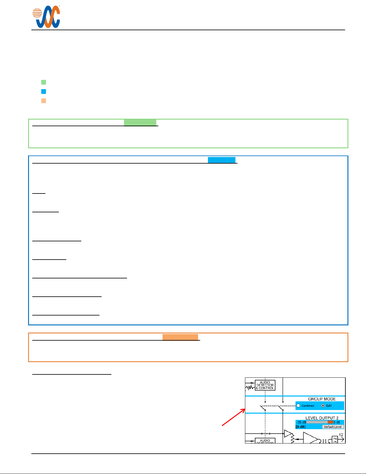
The diagram above shows a typical JA35-100 Settings screen, showing GROUP MODE selected as Combined, and
PRIORITY OUTPUT 1 and PRIORITY OUTPUT 2 both selected Off. Group Modes (section 2.5.4.4) and Priority
settings (section 2.5.4.5) will be described below.
The Settings window is divided into three sections: the Source Selection; the Audio Summing Amplifier; and the
Aircraft Audio System.
• Source Selection
• JA35-100 Audio Summing Amplifier Adjustments
• Aircraft Audio System
Each section is colour-coded to keep the relevant information together.
2.5.4.1 Source Selection (Green block)
The appropriate audio sources (Source 1 thru Source 6) are selected from drop-down lists in this block, and all relevant
configuration information is added automatically. Other sources can be added to the list (see section 2.5.5).
2.5.4.2 JA35-100 Audio Summing Amplifier Adjustments (Blue block)
The blue blocks (labelled GROUP1 and GROUP 2) refer to the adjustments and settings for the JA35-100 Audio
Summing Amplifier. Defaults can be restored by clicking on the ‘Default Level’ buttons.
Input
The level of each INPUT may be adjusted from 1.5 to 10.0 Vrms. (Default 7.8 Vrms)
Threshold
The input THRESHOLD for Inputs 1-5 may be adjusted from -40 to 0 dB (Default -20 dB) when PRIORITY OUTPUTS are On.
The input THRESHOLDS cannot be adjusted when PRIORITY OUTPUTS are Off,
Detector Off Delay
The DETECTOR OFF DELAY may be adjusted from 0.5 to 2.0 s. (Default 1.0 s)
Output Level
The level for OUTPUTS 1 and 2 may be adjusted from -35 to 0 dB. (Default 0 dB)
Group 1 and 2 Priority (See 2.5.4.4)
The priority for GROUP 1 and 2 PRIORITY may be selected as On or Off.
Group Mode (See 2.5.4.5)
The groups may be either Split or Combined (Default Combined).
Mute Depth (See 2.5.4.6)
In PRIORITY OUTPUT On mode, the mute depth Output for each Group may be adjusted from -60 to 0 dB. (Default -40 dB)
2.5.4.3 Aircraft Audio System Selection (Orange block)
The Aircraft Audio System is selected from a drop-down list at the top of the block, and all relevant configuration
information is added automatically. Other Audio Systems can be added to the list (see section 2.5.5).
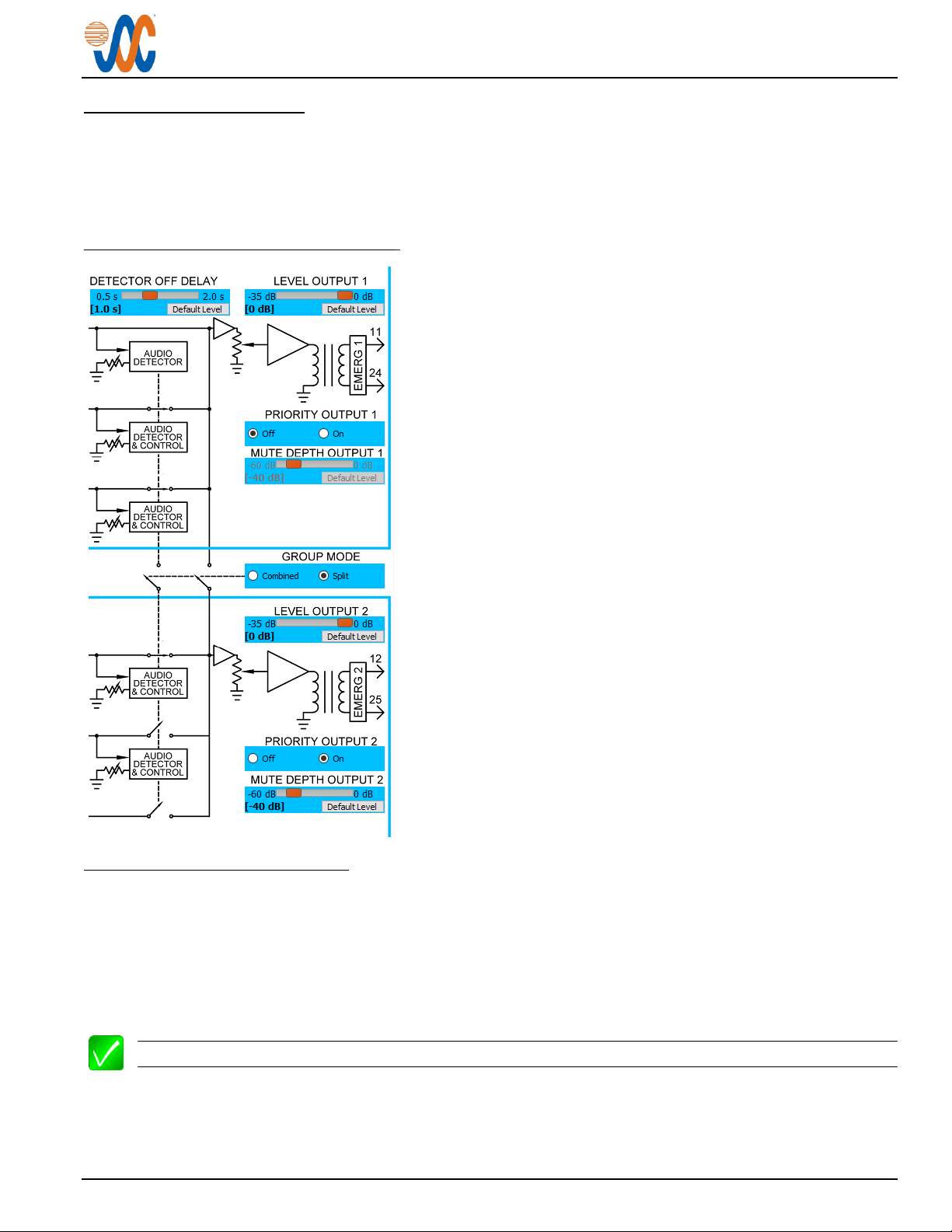
2.5.4.4 Group Modes
The audio inputs 1, 2, 3, 4, 5 and 6 are routed to the Output 1 & 2 when the
GROUP MODE is set to Combined.
The audio inputs 1, 2 and 3 (referred to as GROUP 1) are routed to Output
1 and the audio inputs 4, 5 and 6 (referred to as GROUP 2) are routed to
Output 2 when the GROUP MODE is set to Split.
Split Mode
Rev A Page 6
Page 10
JA35-100 Audio Summing Amplifier - Remote Mount
Installation and Operating Manual
2.5.4.5 Priority Settings
The audio inputs are summed and routed to the output when PRIORITY is set to Off.
The lower numbered audio inputs will mute higher numbered audio inputs when the lower numbered audio input level
is above the associated threshold level and PRIORITY is set to On. The unmuted audio input is routed to the audio
output.
2.5.4.6 Priority and Group Operation
The lower numbered audio inputs 1 to 5 will mute higher numbered
audio inputs 2 to 6 when the lower numbered audio input level is
above the associated threshold level, PRIORITY is set to On and the
GROUP MODE is set to Combined.
The lower numbered audio inputs 1 and 2 will mute higher numbered
audio inputs 2 and 3 when the lower numbered audio input level is
above the associated threshold level, PRIORITY is set to On and the
GROUP MODE is set to Split.
Also, the lower numbered audio inputs 4 and 5 will mute higher
numbered audio inputs 5 and 6 when the lower numbered audio
input level is above the associated threshold level, PRIORITY is set
to On and the GROUP MODE is set to Split.
T
his diagram shows Split GROUP MODE, with GROUP 1 in
PRIORITY Off mode and GROUP 2 in PRIORITY On mode.
2.5.4.7 Mute Depth Operation
The MUTE DEPTH OUTPUT 1 adjusts the reduction in level of audio input 2 and 3 when PRIORITY is On and a
lower numbered audio input level is above the associated threshold level.
The MUTE DEPTH OUTPUT 2 adjusts the reduction in level of audio input 4, 5 and 6 when PRIORITY is On and a
lower numbered audio input level is above the associated threshold level.
The extent to which the higher number audio inputs are muted is controlled by the mute depth level and is applicable
only when PRIORITY is set to On.
Note: No reduction in level is perceived when an audio input is muted and the muting depth is set to 0 dB.
Rev A Page 7
Page 11
Standard D-Sub Crimp Tool Chart
Tool Type
Hand crimping tool
Positioner
Insertion/extractor tool
POSITRONIC
9507-0-0-0
9502-5-0-0
4711-2-0-0
DANIELS
AFM 8
K13-1
91067-2
MIL-SPEC
M22520/2-01
M22520/2-08
M81969/1-02
JA35-100 Audio Summing Amplifier - Remote Mount
Installation and Operating Manual
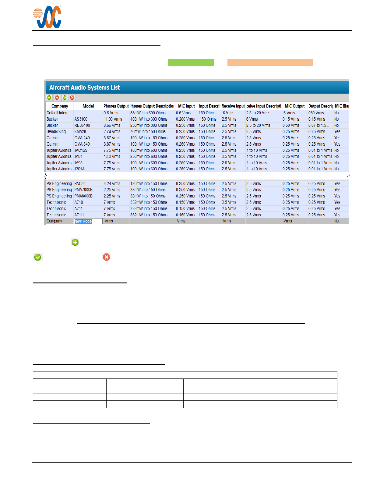
2.5.5 Aircraft Audio System List
This is a list of Aircraft Audio Systems and sources, and shows the configuration information that will be added to the
JA35-100 Settings page. It is used with both the Source Selection and Aircraft Audio System Selection drop-down
menus.
To add other Audio Sources, click on the Audio Source List. A new audio source and its parameters can be added
by clicking on (the ‘New Audio Sources ' button). A new line will be added to the bottom of the list, and double
clicking on each part of the line will highlight it to allow changes. When the relevant details have been added, use the
(‘Save Changes’) or (‘Cancel All Changes’) button as required. The added source will then appear on the
appropriate drop-down menu list.
2.6 Installation Kit
The kit required to install this unit is not included with the unit.
The installation kit (Part # INST-JA35) consists of the following:
Quantity Description JAC Part #
1 TAG ring CON-5500-0375
1 D-Sub 25-pin connector, hood and 25 crimp pins CON-3420-0025
1 Heat Shrink Tubing WIR-HTSK-750
2.6.1 Recommended Crimp tools
2.7 Installation Drawings
The drawings and documents required for Installation can be found in Appendix A of this manual.
Rev A Page 8
Page 12
JA35-100 Audio Summing Amplifier - Remote Mount
SECTION 3 – OPERATION
3.1 Introduction
This section contains the operating instructions for the JA35-100.
3.2 Emergency/Normal Mode Operation
Note: The JA35-100 has no integrated operator controls. However, a remote-mounted NORM/EMER switch
or button may be installed, which affects the operation of the unit.
3.3 System Operation
All operation is described for normal operating and emergency operating mode with aircraft electrical power supplied,
unless stated otherwise.
CAUTION: The JA35-100 is configurable for several different operational modes. Check the configuration of
your unit with the installing agency
3.3.1 Normal Mode of Operation
The JA35-100 is in Normal mode when the aircraft electrical power is applied to the +28VDC POWER INPUT and any
external Normal/Emergency (NORM/EMER) switch is set to NORM.
3.3.2 Emergency Mode Operation
The JA35-001 is in Emergency Mode when the electrical power is not applied to the +28VDC POWER INPUT or any
external Normal/Emergency (NORM/EMER) switch is set to EMER.
In Emergency Mode, the JA35-100 Input 1 and Input 4 are routed directly through mechanical relay contacts to the
Output 1 and Output 2 respectively.
3.3.3 Audio Input Combined Operation
When the JA35-100 is configured for Audio Input COMBINED Operation, all six audio inputs are summed into both
the outputs.
3.3.4 Audio Input Split Operation
When the JA35-100 is configured for Audio Input Split Operation, the first three audio inputs are summed into
Output 1 and the second three audio inputs are summed into Output 2.
3.3.5 Audio Input Combined Priority Operation
When the JA35-100 is configured for Audio Input Combined Priority, it mutes all audio from inputs with a higher input
number, i.e. Input 1 will mute all inputs greater than 1.
3.3.6 Audio Input Split Priority Operation
When the JA35-100 is configured for Audio Input Split Priority, all audio from inputs with a higher input number but
less than 4 is muted for the first three inputs and all audio from inputs with a higher number than 4 is muted for the
second three inputs.
Rev A Page 9
Page 13

JA35-100 Audio Summing Amplifier - Remote Mount
Installation and Operating Manual
Appendix A - Installation Drawings
A1 Introduction
The drawings necessary for installation and troubleshooting of the JA35-100 Audio Summing Amplifier - Remote
Mount are in this Appendix, as listed below.
A2 Installation Drawings
DOCUMENT Rev
JA35-100 Connector Map A
JA35-100 Interconnect A
JA35-100 Mechanical Installation B
Rev A Page A1
Page 14
JUPITER AVIONICS TEMPLATE AUTOCAD PORTRAIT SIZEA REV B.DWT
TITLE
APPROVED
PREPARED
CHECKED
L00N3
NCAGE CODE PART NO. SHEET
DOC NO.
CONFIDENTIAL & PROPRIETARY
TO JUPITER AVIONICS CORP.
Audio Summing Amplifier - Remote Mount
JA35-100 1/1
JA35-100 Connector Map Rev A.dwg
TAT
1 2 3 4 5
14 15 16 17
+28 VDC POWER
NORM MODE SELECT
AUDIO INPUT1 HI
AUDIO INPUT2 HI
P1
25 PIN FEMALE DMIN
MATING CONNECTOR
VIEW IS FROM REAR OF MATING CONNECTOR
6 7 8
1918
AUDIO INPUT6 HI
AUDIO INPUT3 HI
AUDIO INPUT4 HI
AUDIO INPUT5 HI
9 10 11 12 13
SPARE 1
SPARE 2
AUDIO OUTPUT 1 HI
AUDIO OUTPUT 2 HI
SPARE 3
AUDIO INPUT2 LO
AUDIO INPUT6 LO
AUDIO INPUT3 LO
AUDIO INPUT4 LO
AUDIO INPUT5 LO
SPARE 4
AUDIO OUTPUT 2 LO
POWER GROUND
CHASSIS GROUND
AUDIO INPUT1 LO
SPARE 5
AUDIO OUTPUT 1 LO
20 21 22 23 2524
P2
4 POLE MALE 3.5MM PLUG
TIP: TX DATA
1ST RING: RX DATA
2ND RING: GROUND
3RD RING: MODE SELECT
ACCEPTS THE FOLLOWING PLUG FORMATS
JA99-001 CONFIGURATION CABLE
MATING PLUG NAMES JA35 SIGNAL NAMES
CONFIG DATA TO JA35
CONFIG DATA FROM JA35
GROUND
MODE SELECT
CONFIGURATION CONNECTOR
CAB-USB-0006 or
03-08-19
SRM
03-08-19
KDV
JAC
JAC
Page 15
JUPITER AVIONICS TEMPLATE AUTOCAD PORTRAIT SIZEA REV B.DWT
TITLE
APPROVED
PREPARED
CHECKED
L00N3
NCAGE CODE PART NO. SHEET
DOC NO.
CONFIDENTIAL & PROPRIETARY
TO JUPITER AVIONICS CORP.
Audio Summing Amplifier - Remote Mount
JA35-100 1/3
JA35-100 Interconnect Rev A.dwg
TAT
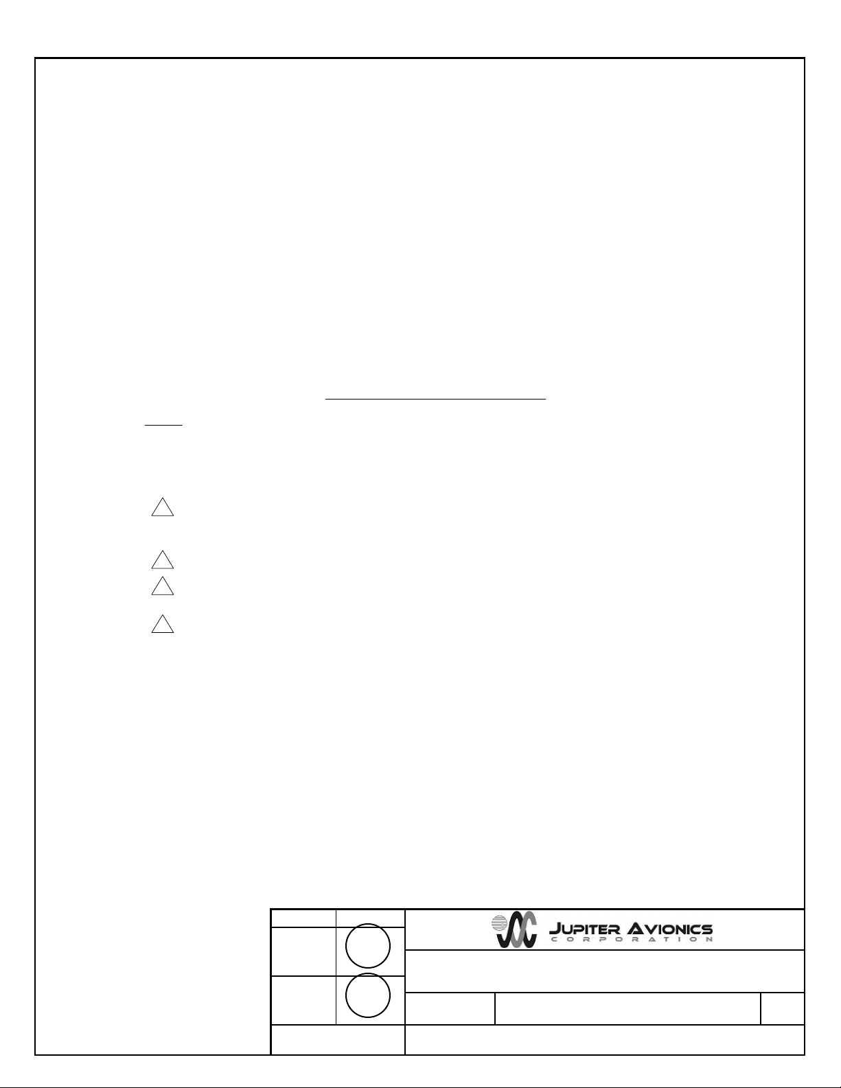
JA35-100 INTERCONNECT WIRING NOTES
NOTES
All wire size should be 24 AWG min unless otherwise specified. Unshielded wire should be selected per
FAA AC43.13-1B change 1 para 11-76 TO 11-78. Wire types should be in accordance with MIL-W-22759
as described in FAA AC43.13-1B change 1 para 11-85 and 11-86 and listed in table 11-11 or 11-12. All
shielded cable should be in accordance with MIL-DTL-27500 (Revision H or later).
Outputs are transformer coupled (Balanced), Connect AUDIO OUTPUT LO to destination equipment
audio input lo. If destination equipment does not have an audio lo contact, connect AUDIO OUTPUT LO
to ground near destination power ground.
Connection to airframe ground should be made with 20 AWG wire. Length not to exceed 3 FT (0.9 M).
Cable shields at connector pins should be terminated to airframe ground using a tag ring P/N:
MS27741-3 or equivalent.
Ground pin for Norm Mode operation or leave pin open for Emerg Mode operation. Normal / Emergency
Switch is optional.
2
1.
3
4
5
03-08-19
SRM
03-08-19
KDV
JAC
JAC
Page 16
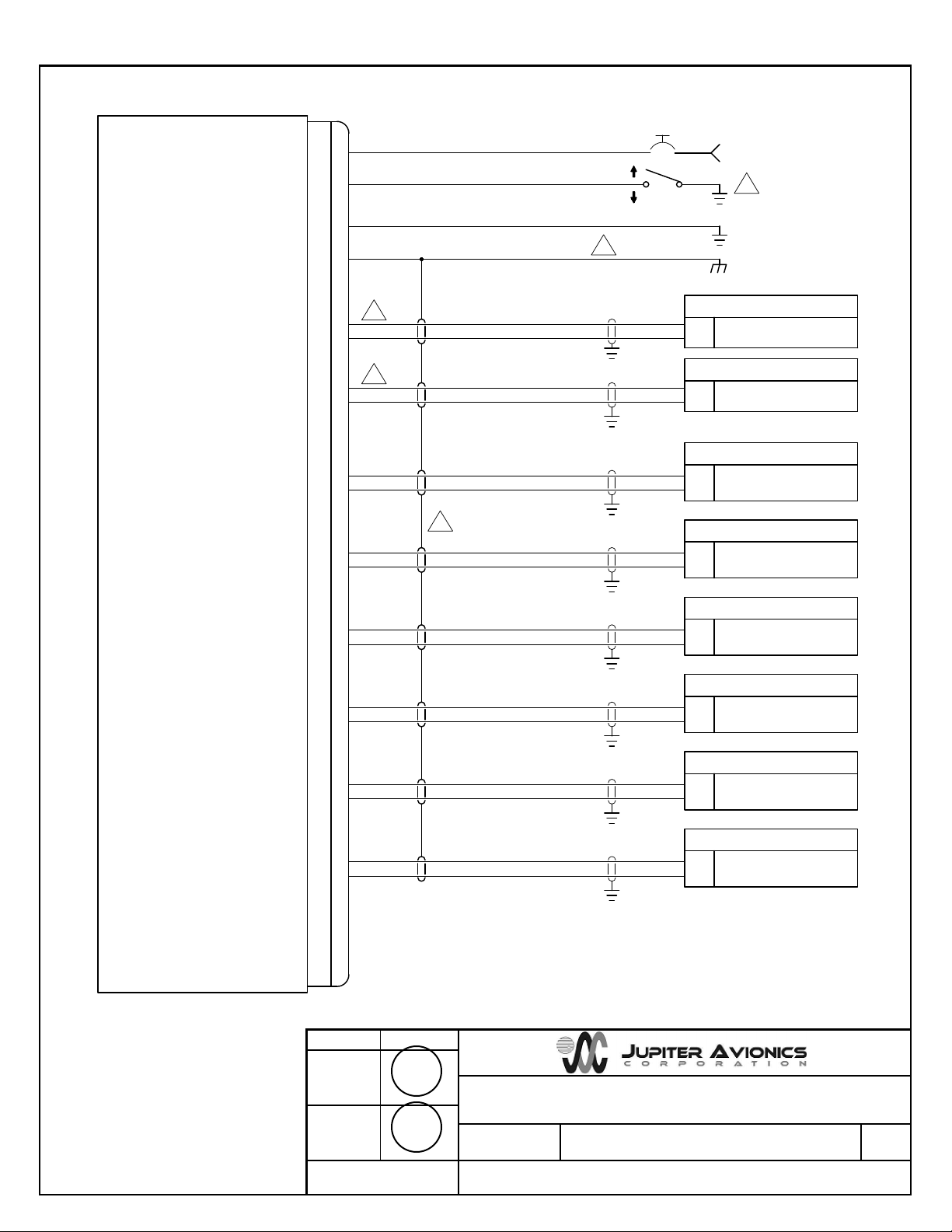
AUDIO OUTPUT 1 HI
AUDIO OUTPUT 1 LO
DIRECT AUDIO 1 HI
DIRECT AUDIO 1 LO
AUDIO CONTROLLER 1
11
24
JA35-100 J1
P1
25 PIN FEMALE DMIN
MATING CONNECTOR
JUPITER AVIONICS TEMPLATE AUTOCAD PORTRAIT SIZEA REV B.DWT
TITLE
APPROVED
PREPARED
CHECKED
L00N3
NCAGE CODE PART NO. SHEET
DOC NO.
CONFIDENTIAL & PROPRIETARY
TO JUPITER AVIONICS CORP.
Audio Summing Amplifier - Remote Mount
JA35-100 2/3
JA35-100 Interconnect Rev A.dwg
TAT
AUDIO OUTPUT 2 HI
AUDIO OUTPUT 2 LO
12
25
DIRECT AUDIO 1 HI
DIRECT AUDIO 1 LO
AUDIO INPUT 1 HI
AUDIO INPUT 1 LO
3
16
AUDIO OUTPUT HI
AUDIO OUTPUT LO
DIRECT AUDIO SOURCE 1
+28 VDC POWER +28 VDC POWER1
NORM MODE SELECT
2
POWER GROUND 14
CHASSIS GROUND
15
POWER GROUND
22 AWG.
22 AWG.
1A
3
20 AWG.
2
2
AUDIO INPUT 2 HI
AUDIO INPUT 2 LO417
AUDIO OUTPUT HI
AUDIO OUTPUT LO
DIRECT AUDIO SOURCE 2
AUDIO INPUT 3 HI
AUDIO INPUT 3 LO
5
18
AUDIO OUTPUT HI
AUDIO OUTPUT LO
DIRECT AUDIO SOURCE 3
AUDIO INPUT 4 HI
AUDIO INPUT 4 LO
6
19
AUDIO OUTPUT HI
AUDIO OUTPUT LO
DIRECT AUDIO SOURCE 4
AUDIO INPUT 5 HI
AUDIO INPUT 5 LO
7
20
AUDIO OUTPUT HI
AUDIO OUTPUT LO
DIRECT AUDIO SOURCE 5
AUDIO INPUT 6 HI
AUDIO INPUT 6 LO
8
21
AUDIO OUTPUT HI
AUDIO OUTPUT LO
DIRECT AUDIO SOURCE 6
4
SPARE 1
SPARE 2
9
10
SPARE 3
13
SPARE 4
22
SPARE 5
23
AUDIO CONTROLLER 2
EMERG MODE
NORMAL MODE
5
03-08-19
SRM
03-08-19
KDV
JAC
JAC
Page 17
JUPITER AVIONICS TEMPLATE AUTOCAD PORTRAIT SIZEA REV B.DWT
TITLE
APPROVED
PREPARED
CHECKED
L00N3
NCAGE CODE PART NO. SHEET
DOC NO.
CONFIDENTIAL & PROPRIETARY
TO JUPITER AVIONICS CORP.
Audio Summing Amplifier - Remote Mount
JA35-100 3/3
JA35-100 Interconnect Rev A.dwg
TAT
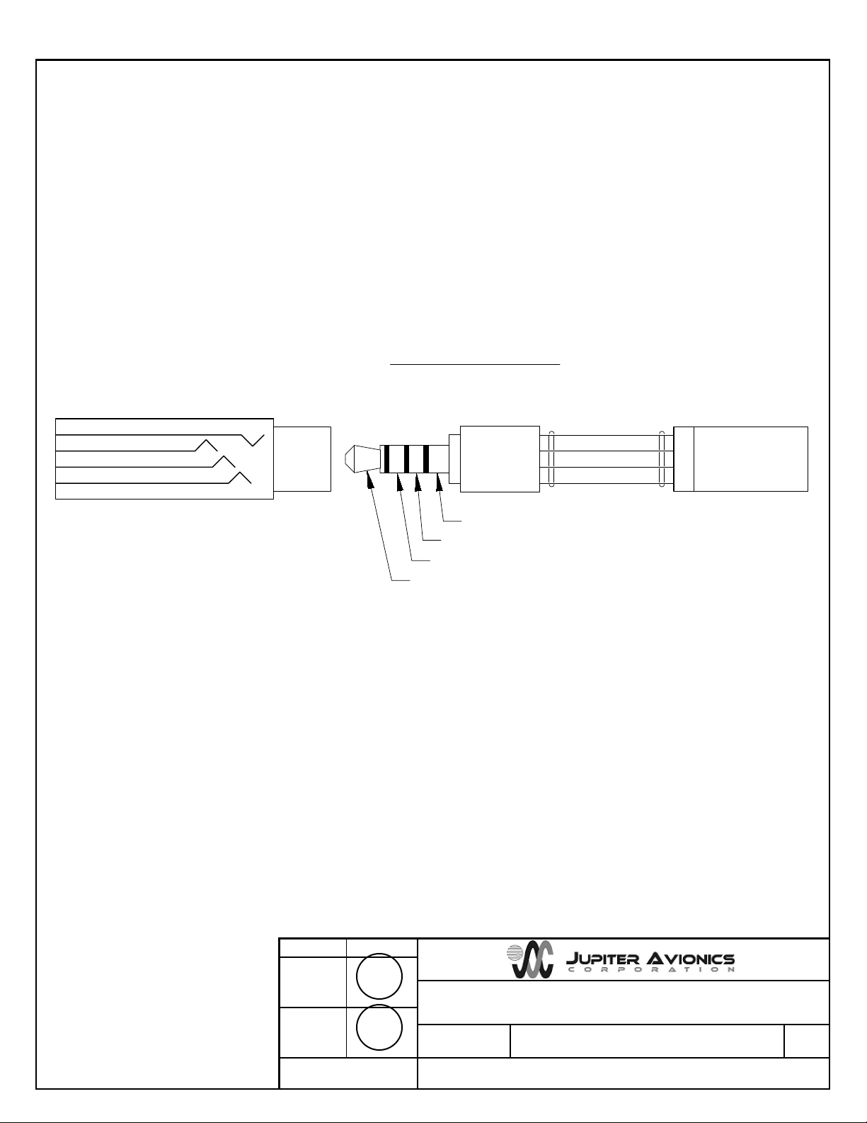
PART OF
CONFIGURATION CABLE
CAB-USB-0006
or JA99-001
JA35-100 CONFIGURATION CONNECTOR
4 POLE MALE 3.5MM STEREO
MATING CONNECTOR
CONFIGURATION CONNECTOR
J2
CONFIG DATA TO JAxx
CONFIG DATA FROM JAxx
GROUND
MODE SELECT
CONFIG DATA TO JA35
CONFIG DATA FROM JA35
GROUND
3RD RING
TIP
1ST RING
2ND RING
MODE SELECT/CONFIG AUDIO
03-08-19
SRM
03-08-19
KDV
JAC
JAC
Page 18
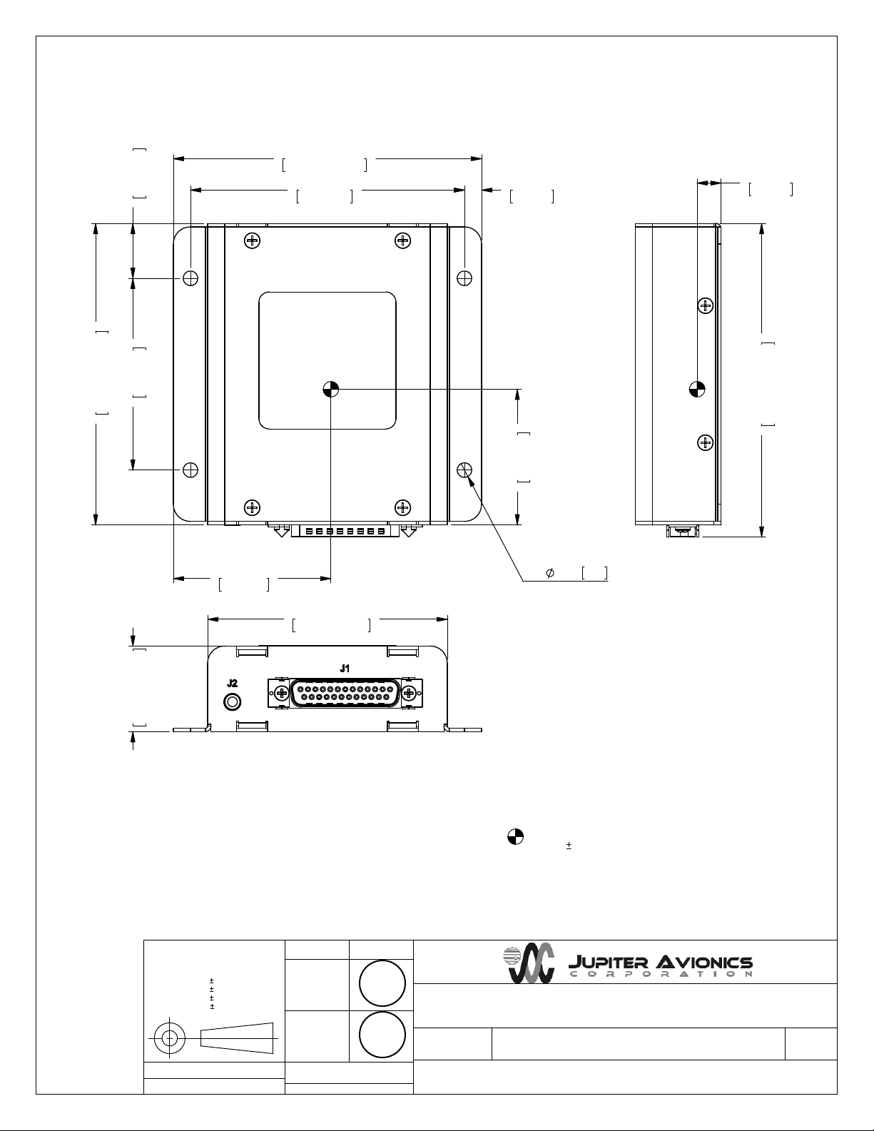
0.80in
20.3mm
4.52in MAX
114.8mm MAX
4.00in
101.6mm
0.35in
8.9mm
0.25in
6.4mm
4.42in MAX
112.3mm MAX
2.80in
71.1mm
1.27in MAX
32.3mm MAX
2.30in
58.4mm
3.52in MAX
89.4mm MAX
1.98in
50.3mm
117.1mm MAX
4.61in MAX
0.21 5.44 x
UNLESS OTHERWISE SPECIFIED
DIMENSIONS ARE IN INCHES
ANGLES ARE IN DEGREES
TOLERANCES:
1 DEC PLACE: 0.1
2 DEC PLACE: 0.01
3 DEC PLACE: 0.005
ANGLES:
MATERIAL:
JUPITER AVIONICS TEMPLATE SOLIDWORKS PORT R AI T SI Z EA REVB . D RW D O T
FINISH:
0.5 DEG
N/A
N/A
PREPARED
TAT
JAC
CHECKED
03-08-19
SRM
JAC
APPROVED
CONFIDENTIAL & PROPRIETARY
TO JUPITER AVIONICS CORP.
DRAWING NOT TO SCALE
03-08-19
KDV
CENTER OF GRAVITY
0.03in [0.8mm]
WEIGHT: 0.55 lbs [0.25 kg] MAX.
TITLE
Audio Summing Amplifier - Remote Mount
NCAGE CODE
L00N3
DOC. NO.
PART NO.
JA35-100
JA35-100 Mechanical Installation Rev B.SLDDRW
SHEET
1/1
Page 19

JA35-100 Audio Summing Amplifier - Remote Mount
Installation and Operating Manual
Appendix B - Installation Documents
Rev A Page B1
Page 20

JA35-100 Audio Summing Amplifier - Remote Mount
Installation and Operating Manual
B1 Airworthiness Approval
Airworthiness approval of the JA35-100 may require completion of a TCCA Major Modification Report per CAR STD
(AWM) 571 Appendix L, or a FAA Form 337. The sample wording for a description of the work is provided to assist
the Installing Agency in preparing Instructions for Continued Airworthiness (ICA) when replacing existing equipment
with a Jupiter Avionics JA35-100 Audio Summing Amplifier - Remote Mount. This sample may be modified
appropriately for new installations. It is the installer’s responsibility to determine the applicability of the method used.
Installations performed outside Canada must follow the applicable aviation authority’s regulations.
Sample Wording:
Removed the existing [model] equipment and replaced with a Jupiter Avionics JA35-100 Audio Summing Amplifier Remote Mount in [aircraft location].
Installed in accordance with the JA35-100 Installation Manual, Revision [ ], and AC 43.13-2, Chapters 2, and 3.
The JA35-100 interfaces with existing aircraft systems per the Installation Manual instructions.
The JA35-100 Installation Manual provides detailed installation instructions and wiring diagrams (Section 2, and
Appendices A and B).
Power is supplied to the JA35-100 through an existing [ ]-Amp circuit breaker that was previously used by the original
equipment. The net electrical load is unchanged.
Aircraft equipment list, weights and balance amended. Compass compensation checked and found to conform to
applicable regulations.
B2 Instructions for Continued Airworthiness
Maintenance of the JA35-100 Audio Summing Amplifier - Remote Mount is “on condition” only. Refer to the JA35-100
Maintenance Manual. Periodic maintenance of the JA35-100 is not required.
The following sample Instructions for Continued Airworthiness (ICA) provides assistance in preparing ICA for the
Jupiter Avionics JA35-100 unit installation as part of a Type Certificate (TC) or Supplemental Type Certificate (STC)
project to comply with CAR STD (AWM) 523/527/525/529.1529 or FAR 23/25/27/29.1529 “Instructions for Continued
Airworthiness”.
Items that may vary by aircraft make and model are shown in brackets (“[ ]”) and should be filled in as appropriate.
Some of the checklist items do not apply, in which case they should be marked “N/A” (Not Applicable).
Instructions for Continued Airworthiness, Jupiter Avionics JA35-100 Audio
Summing Amplifier - Remote Mount in an [Aircraft Make and Model]
1. Introduction
[Aircraft that has been altered: Registration number, Make, Model and Serial Number]
Content, Scope, Purpose and Arrangement: This document identifies the Instructions for Continued
Airworthiness for a Jupiter Avionics JA35-100 installed in an [aircraft make and model].
Applicability: Applies to a Jupiter Avionics JA35-100 installed in an [aircraft make and model].
Definitions/Abbreviations: None, N/A.
Precautions: None, N/A.
Units of Measurement: None, N/A.
Referenced Publications: JA35-100 Installation and Operating Manual
JA35-100 Maintenance Manual
JA35-100 Operating Manual
STC/TC # [applicable STC/TC number for the specific aircraft installation]
Distribution: This document should be a permanent aircraft record.
Rev A Page B2
Page 21

JA35-100 Audio Summing Amplifier - Remote Mount
Installation and Operating Manual
2. Description of the System/Alteration
Jupiter Avionics JA35-100 Audio Summing Amplifier - Remote Mount with interface to external transceivers and
[include other equipment/systems as appropriate]. Refer to Appendix A of this manual for interconnect
information. Refer to aircraft manufacturer approved interconnect for actual installation.
3. Control, Operation Information
N/A
4. Servicing Information
N/A
5. Maintenance Instructions
Maintenance of the JA35-100 is ‘on condition’ only. Periodic maintenance is not required. Refer to the
JA35-100 Maintenance Manual.
6. Troubleshooting Information
Refer to the JA35-100 Maintenance Manual.
7. Removal and Replacement Information
Refer to Section 2 of this manual - the JA35-100 Installation and Operating Manual. If the unit is removed and
reinstalled, a functional check of the equipment should be conducted.
8. Diagrams
Refer to Appendix A of this manual - the JA35-100 Installation and Operating Manual - for installation drawings
and interconnect examples.
9. Special Inspection Requirements
N/A
10. Application of Protective Treatments
N/A
11. Data: Relative to Structural Fasteners
JA35-100 and appropriate mounting hardware installation, removal and replacement should be in accordance
with applicable provisions of AC 43.13-1B and AC 43.13-2A.
12. Special Tools
N/A
13. This Section is for Commuter Category Aircraft Only
A. Electrical loads: Refer to Section 1 of the JA35-100 Installation and Operating Manual.
B. Methods of balancing flight controls: N/A.
C. Identification of primary and secondary structures: N/A.
D. Special repair methods applicable to the airplane: N/A.
14. Overhaul Period
No additional overhaul time limitations.
15. Airworthiness Limitation Section
N/A
Rev A Page B3
 Loading...