

Page 1

Check
..........................................................................................................
1
1,Check the package
......................................................................
1
2,Check the accessories
................................................................
1
3,Check the whole machine
...........................................................
1
Chapter 1 Overview
................................................................................
2
1, The instrument profile
....................................................................
2
2, The instrument features
................................................................
3
3, Technical indicators
.......................................................................
3
Chapter II Instrument Description
.....................................................
5
1, Display instructions
........................................................................
5
2, The display module and measurement module power wiring
diagram
.................................................................................................
7
Chapter III Operating Instructions
....................................................
9
1, The communication connection
...................................................
9
2, The operating instructions
..........................................................
10
Chapter Ⅳ After-sales service
..........................................................
11
Page 2

Check
When you get a new VAT Voltage-Current Meter, we recommend that you
follow the steps below to check the instrument.
1,Check the package
If the package is damaged, please keep the damaged packaging or
cushioning material until the goods have been thoroughly inspected and the
instrument has passed both electrical and mechanical tests. Due to damage
caused by the transport, please contact the shipper and the carrier.,
2,Check the accessories
The contents of the attachment are described below. If the content does not
match or the instrument is damaged, please contact the dealer or our
company.
HOST
:
VAT display module
VAT measurement module
1 piece
1 piece
Accessories: data cable
1 piece
Accessories:temperature sensor
1 piece
Accessories:extension interface 2P line
1 piece
Accessories: manual
1 piece
3,Check the whole machine
If the appearance of the instrument is found damaged, the instrument is not working
properly, or it is failed to pass the performance test, please contact the dealer or our
company.
TEL:0371-86106382 QQ1: 1406921960 QQ2: 3155097720
WEB:www.mhinstek.com
Page 3
Chapter 1 Overview
1, The instrument profile
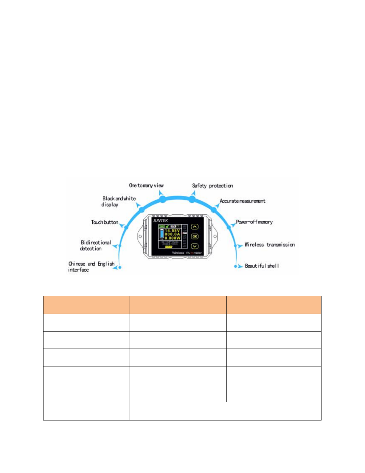
VAT series is a multi-function meter based on 2.4G wireless data
transmission technology. It can measure miscellaneous parameters such as
voltage, current, power, charge and discharge capacity, watt-hour、time,and
temperatureand with over-current protection Protection, under-voltage
protection, and limited protection and other protection functions. The
instrument can automatically identify the direction of the current, and the
battery capacity can be monitored in real time, the instrument uses TFT LCD
display, display information is comprehensive, user-friendly and better
interaction.
2, The instrument features
3, Technical indicators
Model
VAT-1030
VAT-1050
VAT-1100
VAT-1200
VAT-1300
VAT-4300
Voltage measurement range
0~100V
0~100V
0~100V
0~100V
0~100V
0~400V
Voltage resolution
0.01V
0.01V
0.01V
0.01V
0.01V
0.1V
Current measurement range
0~30A
0~50A
0~100A
0~200A
0~300A
0~300A
Current resolution
0.01A
0.01A
0.1A
0.1A
0.1A
0.1A
Relay
Internal
External
(optional)
External
(optional)
External
(optional)
External
(optional)
External
(optional)
Temperature measurement
range
-20~120 ℃
Page 4

Capacity display range
0%~100%
Power measurement range
0~200kW
Power resolution
0.001W
AH measurement range
0~2000kAH
Capacity resolution
0.001AH
Watt-hour measurement range
0~4000kWH
Watt-hour accuracy
0.001WH
Time measurement range
0 ~ 99 days
Time resolution
1 second
Communication channel range
A ~ Z (26 channels)
Communication channel range
01~99
Voltage accuracy
± 2% + 3 words
Current accuracy
± 5% + 10 words
Sampling rate
5 times / second
Communication distance
up to 10 meters
Measurement module power
consumption
About 0.4W
Display module power
consumption
0.5W
NCP
0 ~ 300A (negative over-current protection setting)
OCP
0 ~ 300A (positive over-current protection setting)
OVP
0 ~ 100V (over-voltage protection setting)
LVP
0 ~ 100V (under-voltage protection setting)
protection delay time
0 ~ 10s
Page 5
Chapter II Instrument Description
1, Display instructions
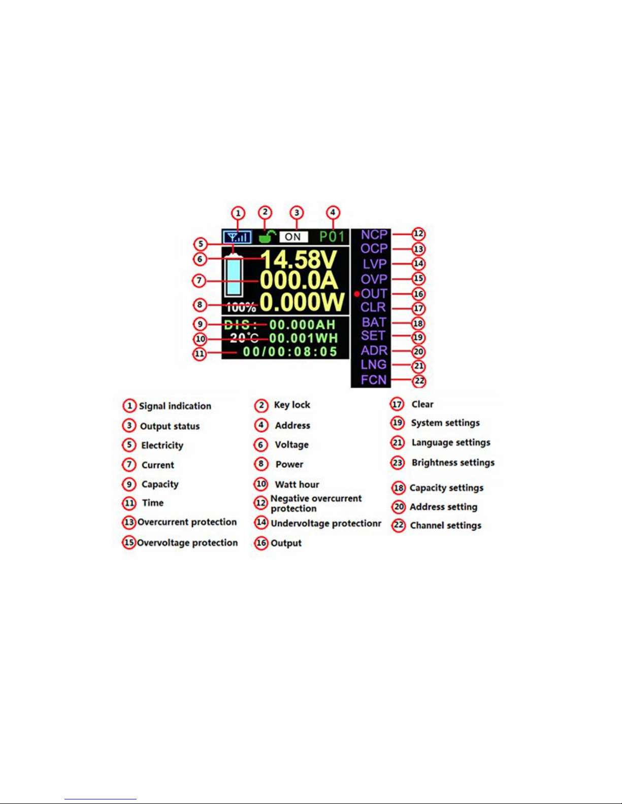
1. The instrument is divided into two parts, including the display module and
measurement module, the display interface in both Chinese and English,
which can be set in the language settings.
Main display panel interface
Page 6
2. The large font interface:
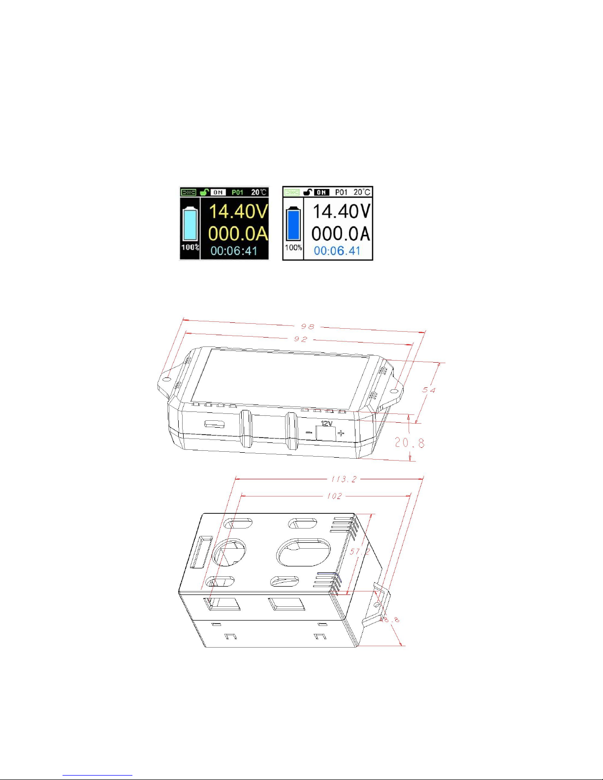
The main parameters such as voltage and current are displayed in the
large font interface for easy observation. After a few seconds, the main
interface will automatically jump to the large font display interface, and the
time can be set in the system settings. Reverse display interface easy to
observe in the light, please read the "Operating Instructions” for details.
3.VAT series display module and measurement module size (in mm)
Page 7
2, The display module and measurement module
power wiring diagram
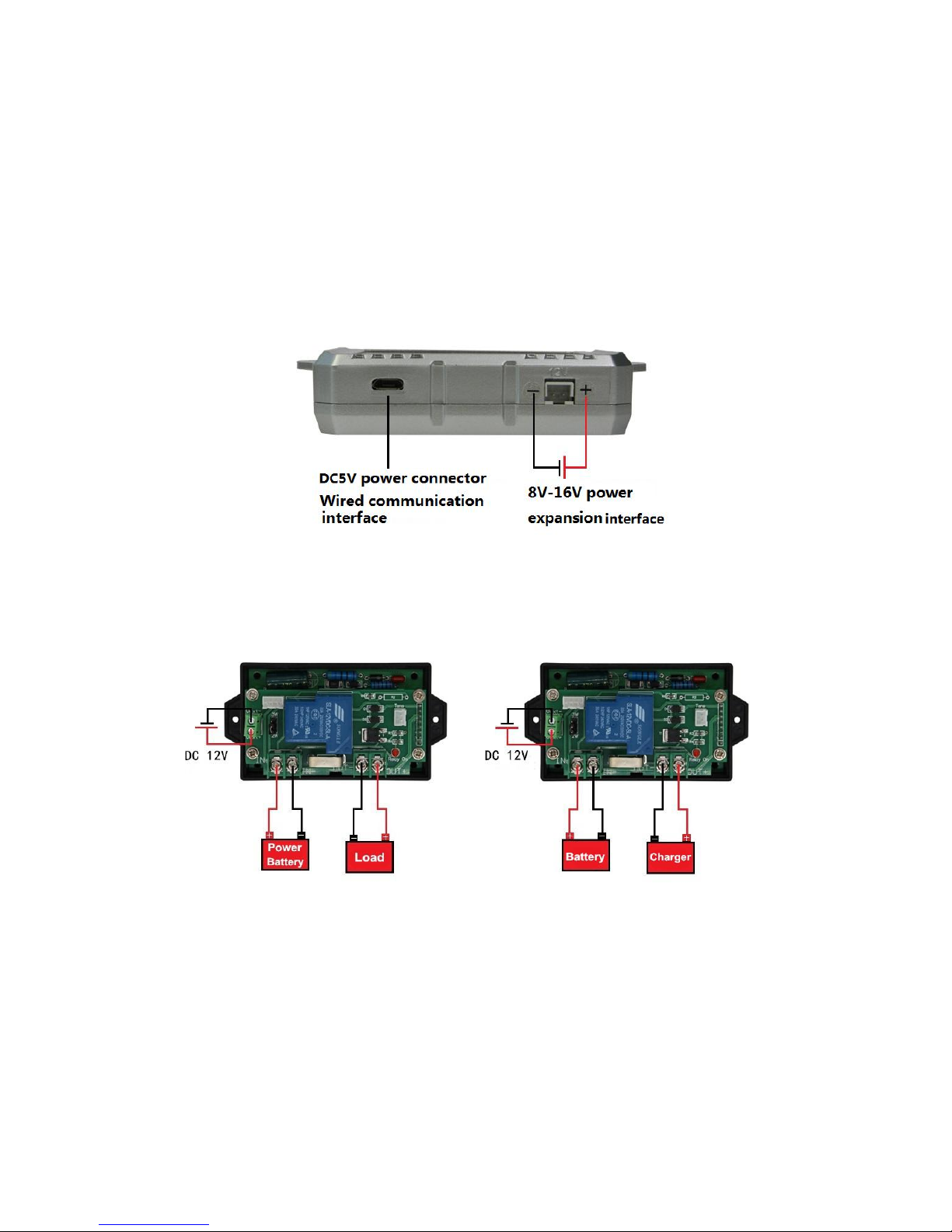
The instrument can be "wired communication" and "wireless communication"
1. Display power supply wiring diagram is as follows:
When the display board is powered separately, there are two power
supply interfaces, which are the USB 5V power supply interface and the 2P
socket interface (8-16V) power supply.
2. Measurement module wiring diagram is as follows:
2.1, VAT1030 wiring diagram:
The wiring method on the left is applicable to the discharge measurement
of the battery and the measurement of the DC circuit; the wiring method on
the right is only applicable to the charge measurement of the battery.
Page 8
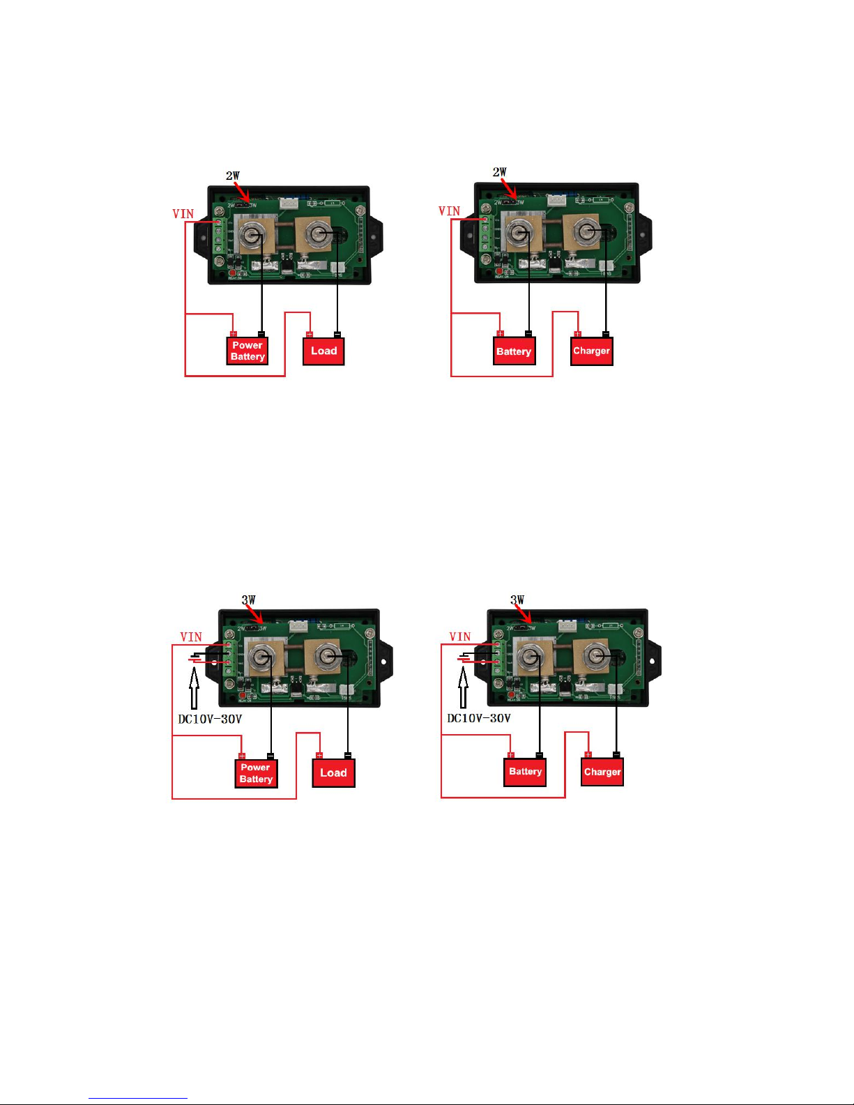
2.2, wiring diagram of VAT1050, VAT1100, VAT1200, VAT1300 measuring
voltage is 10-100V:
The above figure applies to VAT1050, VAT1100, VAT1200, VAT1300
measurement circuit voltage of 10-100V; attention at this time attention to the
jumper cap to receive 2W, the left wiring method is suitable for battery
discharge measurement and DC circuit measurement; The wiring method on
the right is only suitable for charging the battery.
2.3, VAT4300 measurement voltage is 0-400V and VAT1050, VAT1100,
VAT1200, VAT1300 measurement voltage is 0-100V wiring diagram:
The figure above applies to batteries or circuits where the VAT4300
measures 0-400V and VAT1050, VAT1100, VAT1200, and VAT1300 to 0-100V;
at this time, note that the jumper cap must be connected to 3W and need to
use a 10-30V. The DC voltage supplies power to the measurement module;
the wiring method on the left is suitable for the discharge measurement of the
battery and the measurement of the DC circuit; the wiring method on the right
is only suitable for the charge measurement of the battery.
Page 9
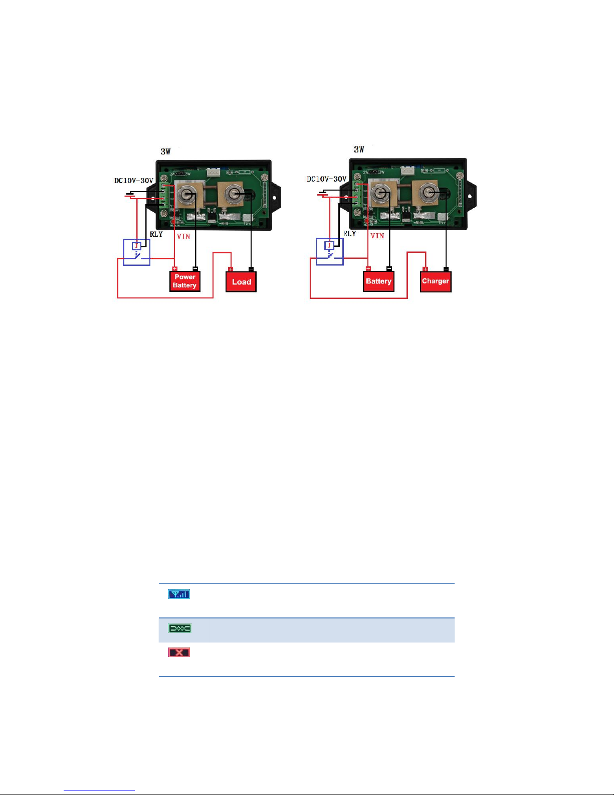
2.4, VAT1050, VAT1100, VAT1200, VAT1300 and VAT4300 external relay
wiring diagram;
The wiring method on the left is applicable to the discharge measurement
of the battery and the measurement of the DC circuit; the wiring method on
the right is only applicable to the charge measurement of the battery.
When selecting the relay, pay attention to the relay's contact can withstand
the maximum current in the circuit, such as the current in the test current is
80A, then select the relay, you must select the contact current can withstand
100A relay, the relay supply voltage can choose 12V or 24V When the 12V
relay is selected, the external power supply voltage must be set to 12V, which
is the same as the relay supply voltage.
Chapter III Operating Instructions
1, The communication connection
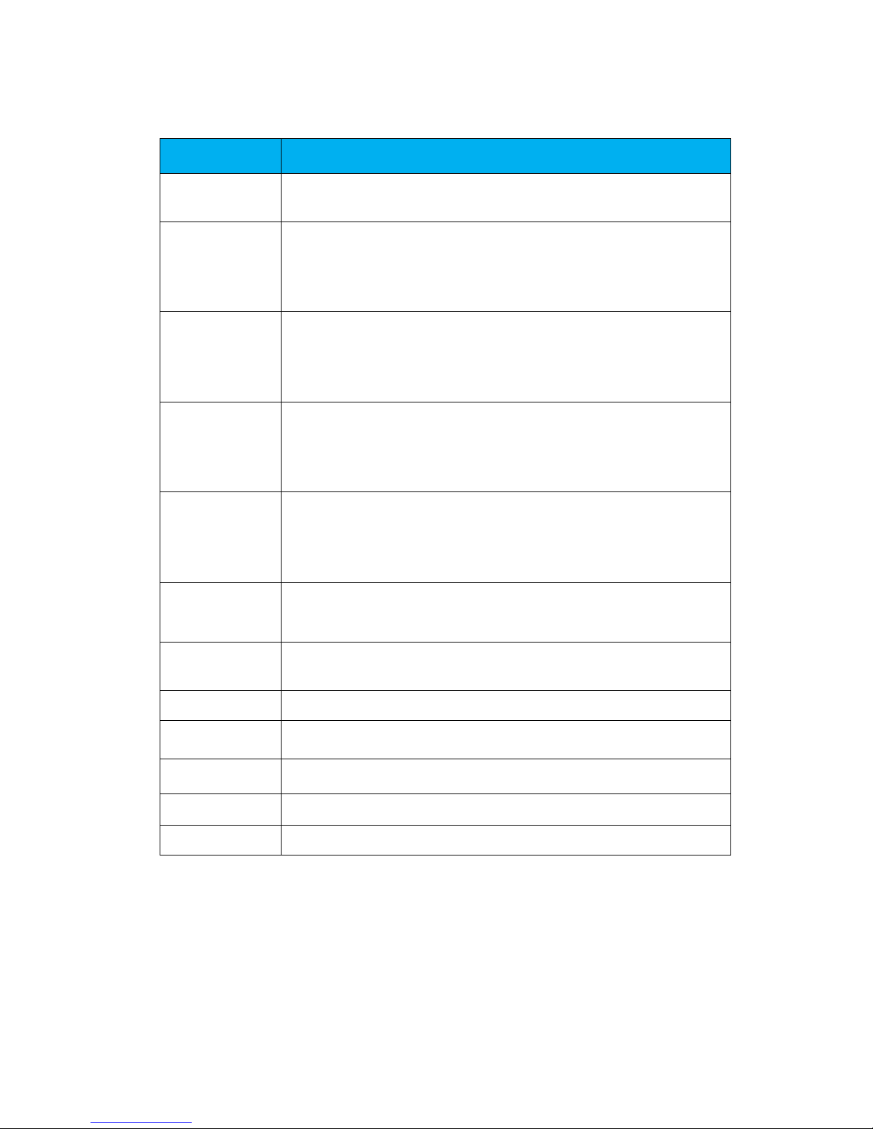
Before operation, please carefully check the wiring is correct, The
connection status is displayed on the top of the screen.
“ ”
Wireless communication connection is
successful
“ ”
Wired communication connection is successful
“ ”
Communication connection failed or not
connected
Page 10
2, The operating instructions
Item
Introduction
“OUT”
This item can control the output status. Parameters will be
saved when set to OFF.Shutdown require relay coordination
“NCP”
This item can set Negative over-current protection.Press
“OK”can change the value, The function will be turned off
when set to 0.
(
The protection function requires the
cooperation of the relay
)
“OCP”
This item can set Posative over-current protection.Press
“OK”can change the value, The function will be turned off
when set to 0. ( The protection function requires the
cooperation of the relay)
“LVP”
This item can set low-voltage protection.Press “OK”can
change the value, The function will be turned off when set to
0. ( The protection function requires the cooperation of the
relay)
“OVP”
This item can set over-voltage protection.Press “OK”can
change the value, The function will be turned off when set to
0. ( The protection function requires the cooperation of the
relay)
“CLR”
This item can clear AH 、WH and time value immediately ,
Real-time battery capacity will be set to 100%.
“BAT”
This item can set the total battery capacity and real-time
battery capacity.
“SET”
This function can set some configurtions of the instrument.
“ADR”
This item can set the Communication address.
“LNG”
This item can set the communication address.
“FCH”
This item can set the communication channel.
“BRI”
This item can set the display brightness.
Note: Leave the cursor at the "ADR" position and long press "DOWN"
key for 3 seconds to switch to the "LNG" option.
Page 11

Chapter
Ⅳ
After-sales service
◆
Product quality problems (non-human caused) in 30 days, unconditional
return policy
◆ The company promises to provide a lifetime warranty for its products, and
does not collect any maintenance fees within one year. It only pays for the
return shipping costs. After one year, the buyer must bear the return shipping
costs.
◆If one of the following conditions is not covered by the warranty: more than
three packs of limited time; failing to comply with the requirements of the
product manual or due to improper use (burning, fluid, or breakage);
disassembling and repairing without permission , upgrades, etc. cause
abnormal functions; damage caused by force majeure.
 Loading...