

Page 1
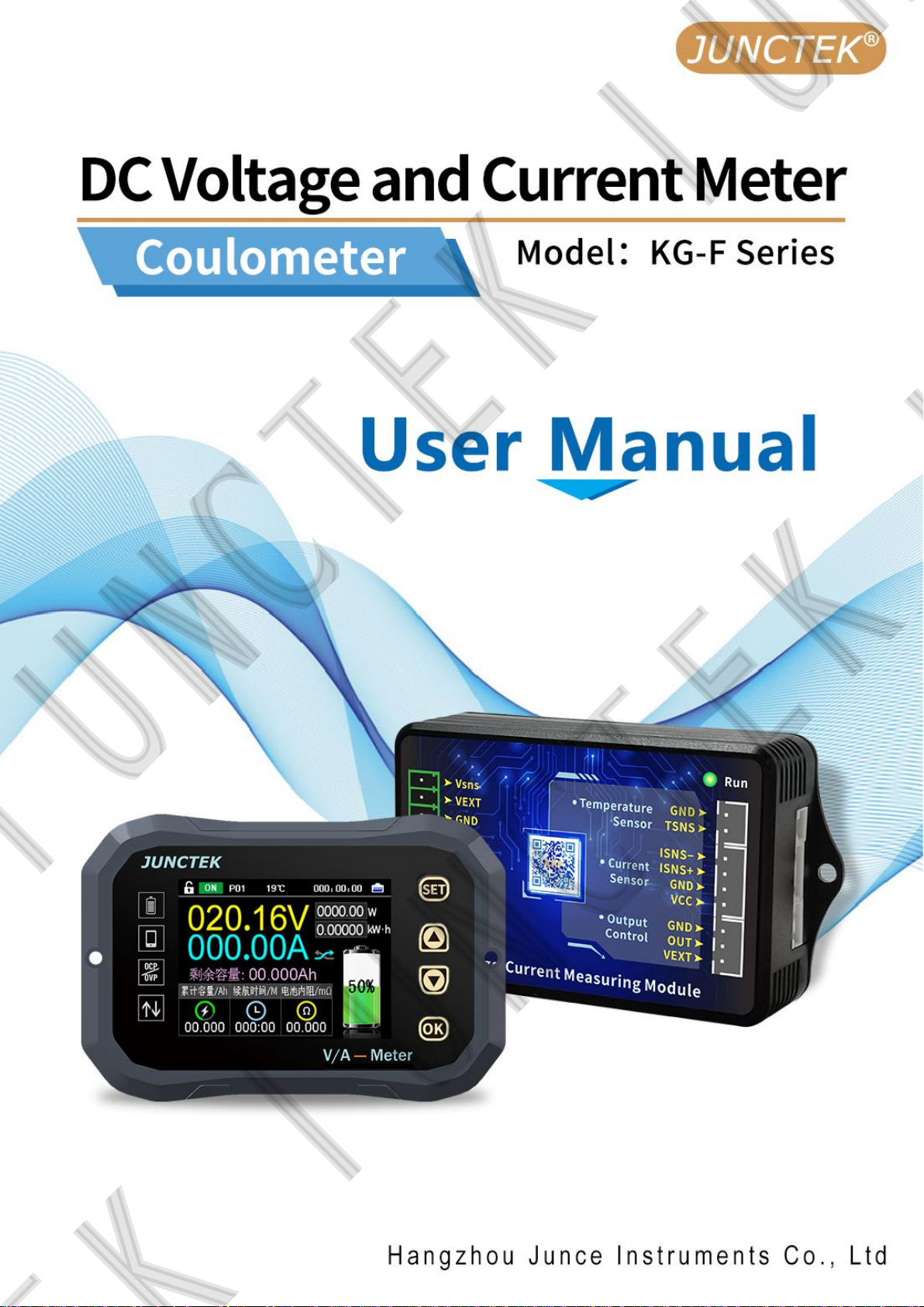
Hangzhou Junce Instruments Co., Ltd.
I
Page 2

Hangzhou Junce Instruments Co., Ltd.
Guaranty and Declaration
Copyright
Hangzhou Junce Instruments Co., Ltd. all right reserved.
Trademark Information
JUNCTEK is a registered trademark of Hangzhou Junce Instruments Co., Ltd.
Notices
JUNCTEK products are covered by P.R.C. patents, issued and pending.
This document replaces all previously published documentation.
Contact Us
If you have any problem or requirement when using our products or this
manual, please contact JUNCTEK.
E-mail: [email protected]
Website: www.junteks.com
I
Page 3

Hangzhou Junce Instruments Co., Ltd.
Safety Requirement
General Safety Summary
Please review the following safety precautions carefully before putting the
meter into operation so as to avoid any personal injury or damage to the meter
and any product connected to it. To prevent potential hazards, please follow
the instructions specified in this manual to use the meter properly.
Observe All Terminal Ratings
To avoid fire or shock hazard, observe all ratings and markers on the meter
and check your manual for more information about ratings before connecting
the meter.
Use Proper Over-voltage Protection
Ensure that no over-voltage (such as that caused by a bolt of lightning) can
reach the product. Otherwise, the operator might be exposed to the danger of
an electric shock.
Do Not Operate Without Covers
Do not operate the meter with covers or panels removed.
Do Not Insert Anything Into the Air Outlet
Do not insert anything into the air outlet to avoid damage to the meter.
Avoid Circuit or Wire Exposure
Do not touch exposed junctions and components when the unit is powered on.
Do Not Operate With Suspected Failures
If you suspect that any damage may occur to the meter, have it inspected by
JUNCTEK authorized personnel before further operations. Any maintenance,
adjustment or replacement especially to circuits or accessories must be
performed by JUNCTEK authorized personnel.
Provide Adequate Ventilation
Inadequate ventilation may cause an increase of temperature in the meter,
which would cause damage to the meter. So please keep the meter well
ventilated and inspect the air outlet and the fan regularly.
Do Not Operate in Wet Conditions
To avoid short circuit inside the meter or electric shock, never operate the
meter in a humid environment.
II
Page 4

Hangzhou Junce Instruments Co., Ltd.
Do Not Operate in an Explosive Atmosphere
To avoid personal injuries or damage to the meter, never operate the meter in
an explosive atmosphere.
Keep Meter Surfaces Clean and Dry
To avoid dust or moisture from affecting the performance of the meter, keep
the surfaces of the meter clean and dry.
Prevent Electrostatic Impact
Operate the meter in an electrostatic discharge protective environment to
avoid damage induced by static discharges. Always ground both the internal
and external conductors of cables to release static before making connections.
Handle with Caution
Please handle with care during transportation to avoid damage to keys, knobs,
interfaces, and other parts on the panels.
Notices
1. Do not exceed the voltage and current range of the meter, otherwise the
meter will be damaged.
2. The positive and negative poles cannot be reversed, and the reverse
connection cannot be handled correctly.
3. The shell of the meter is fragile and easy to corrode. Please don't hit or
close to chemicals to avoid corrosion.
4. Storage temperature: -25~50℃, and keep the meter in a dry environment.
5. Do not attempt to disassemble the meter,it will void the warranty. There are
no user-serviceable parts inside the meter. Repairs can only be made through
designated repair outlets or sent back to the factory.
6. The display screen is a fragile device, please do not touch or bump it .
Please avoid children playing with the meter. When there is dirt on the LCD
surface, wipe it carefully with a soft cloth.
7. Please do not move the meter violently to avoid causing irreparable
damage to the internal circuit. If the meter does not work properly, please
contact the supplier!
III
Page 5

Hangzhou Junce Instruments Co., Ltd.
Contents
General Safety Summary
Notices
1.Brief Introduction
2.Dimensions
3.Specification
1.Introduction of display module
2.Introduction of the measuring module
3.Introduction of the Sampler
4.Introduction of the display interface
1.System settings
2.Wiring method
3.Communication protocol control
4.Mobile APP control
................................................................................................................. III
..............................................................................................3
....................................................................................................... 3
..................................................................................................... 4
..............................................................................................12
................................................................................................ 20
...................................................................................II
.......................................................................6
............................................................................9
............................................................ 10
..................................................................22
........................................................................................ 27
.......................................................... 7
Appendix 1: English and abbreviations of the interface ................. 46
1
Page 6
Hangzhou Junce Instruments Co., Ltd.
Inspection
When you get a new KG-F series coulometer, it is recommended that you
inspect the meter according to the following steps.
Inspect the Packaging
If the packaging has been damaged, do not dispose the damaged
packaging or cushioning materials until the shipment has been checked for
completeness and has passed both electrical and mechanical tests. The
consigner or carrier shall be liable for the damage to the meter resulting from
shipment. We would not be responsible for free maintenance/rework or
replacement of the meter.
Check the Contents
Please check the contents according to the packing lists. If the meter is
damaged or incomplete, please contact your JUNCTEK sales representative.
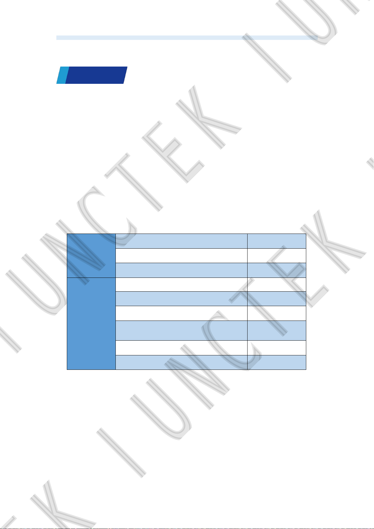
KG-F series of Measuring module 1pc
Host
KG-F series of display module 1pc
KG-F series of the Sampler 1pc
3m communication cable 1pc
Temperature Sensor 1pc
4P connection cable 1pc
Accessory
3P connection cable (external relay
cable)
1pc
Terminal 1pc
Quick guide 1pc
Inspect the Meter
In case of any mechanical damage, missing parts, or failure in passing the
electrical and mechanical tests, contact your JUNCTEK sales representative.
2
Page 7
Hangzhou Junce Instruments Co., Ltd.
Chapter
Overview
Ⅰ
1.Brief Introduction
The KG-F series voltage and current meter is a new type of coulometer
that can measure various parameters such as voltage, current, power, charge
and discharge AH value, watt-hours, time, etc. It can also set parameters to
achieve multi protection functions such as over-voltage protection,
under-voltage protection, over-current protection, over-power protection, over
temperature protection and time limit protection.The meter can automatically
identify the direction of the current, and can monitor the battery capacity in real
time and display the measured data in color LCD screen. The KG-F series
voltage and current meters add voltage and current curve display and export
functions on the basis of the original functions. At the same time, you can use
the mobile APP and the computer to control the measuring module, and the
firmware can also be updated in real time.
2.Dimensions
Dimension of display module
Note: display module inlay hole size: 85.1 * 58.1mm
Dimension of measuring module Hole location of measuring module
Display module hole bitmap
3
Page 8
Hangzhou Junce Instruments Co., Ltd.
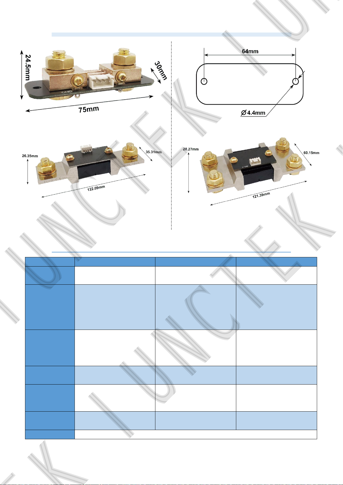
Dimension of the 100A sampler Dimension of the 100A sampler
Dimension of the 400A sampler Dimension of the 600A sampler
3.Specification
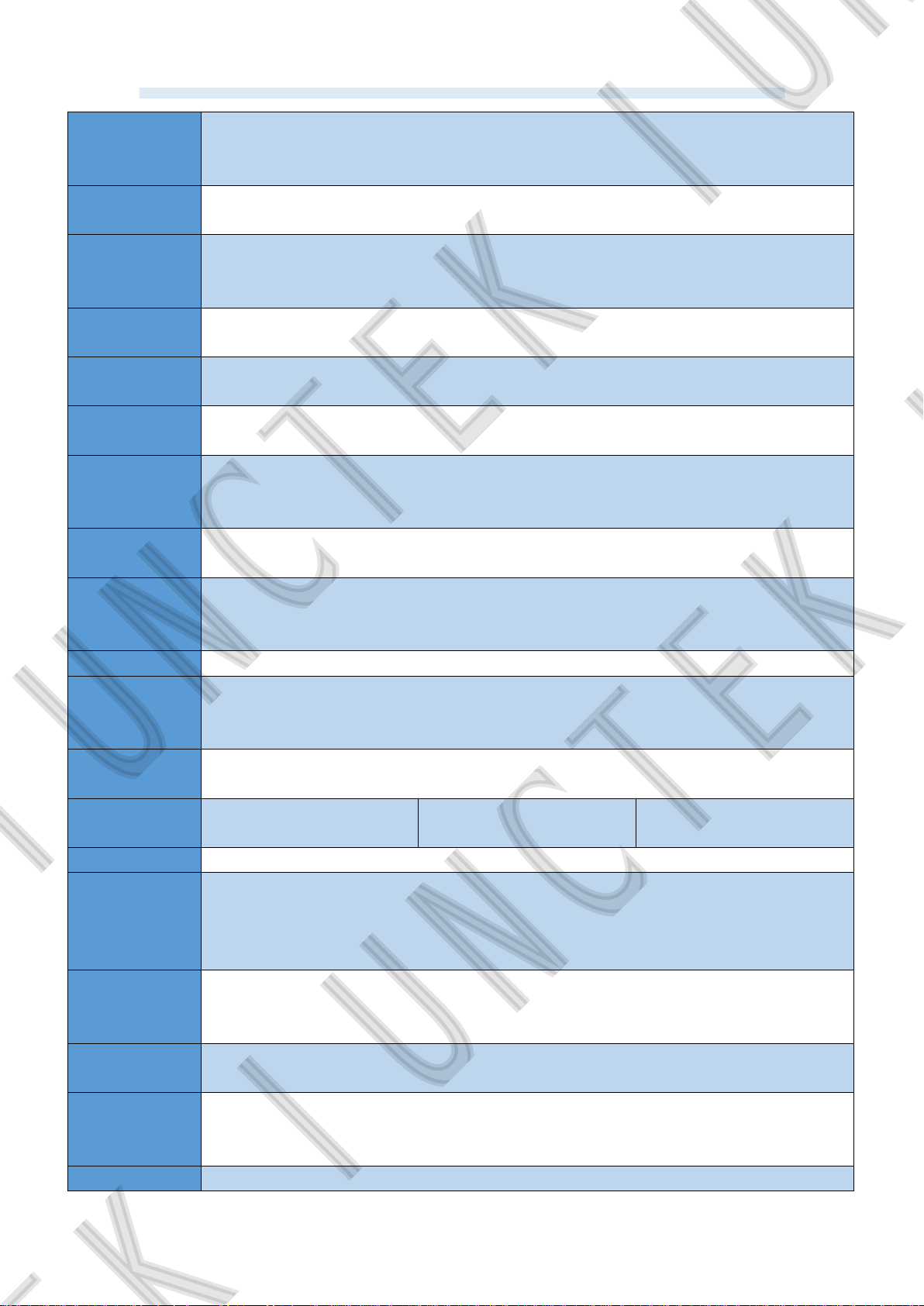
Model KG110F KG140F KG160F
Sampling
method
Voltage
measurement
range
(External power
supply)
Voltage
measurement
range
(Self-powered)
Voltage
resolution
Current
measurement
range
Current
resolution
Relay Optional
The Shunt The Shunt The Shunt
0-120V 0-120V 0-120V
10-120V 10-120V 10-120V
0.01V 0.01V 0.01V
0~100A 0~400A 0~600A
0.01A 0.1A 0.1A
4
Page 9
Hangzhou Junce Instruments Co., Ltd.
Temperature
measurement
-20-120℃
range
Capacity
display range
0%~100%
Power
measurement
0~72KW
range
Power
resolution
AH measureme
nt range
Capacity resolu
tion
0.01W
0~9999.99AH
0.001AH
Watt-hour
measurement
0~9999.99kWH
range
Watt-hour
accuracy
0.001WH
Time
measurement
0~999:59:59S
range
Time resolution 1 second
Bluetooth
communication
10m
distance
Voltage accura
cy
Current accurac
y
±1%+0.02A, ±1%+0.1A ±1%+0.1A
±1%+2 个 digits
Sampling rate 1 time / second
Measuring
module
power
About 0.4W
consumption
Display module
power
About 0.5W
consumption
Over power
protection
0-99999.99W
Negative over
current
100A/400A/600A
protection
Forward over 100A/400A/600A
5
Page 10
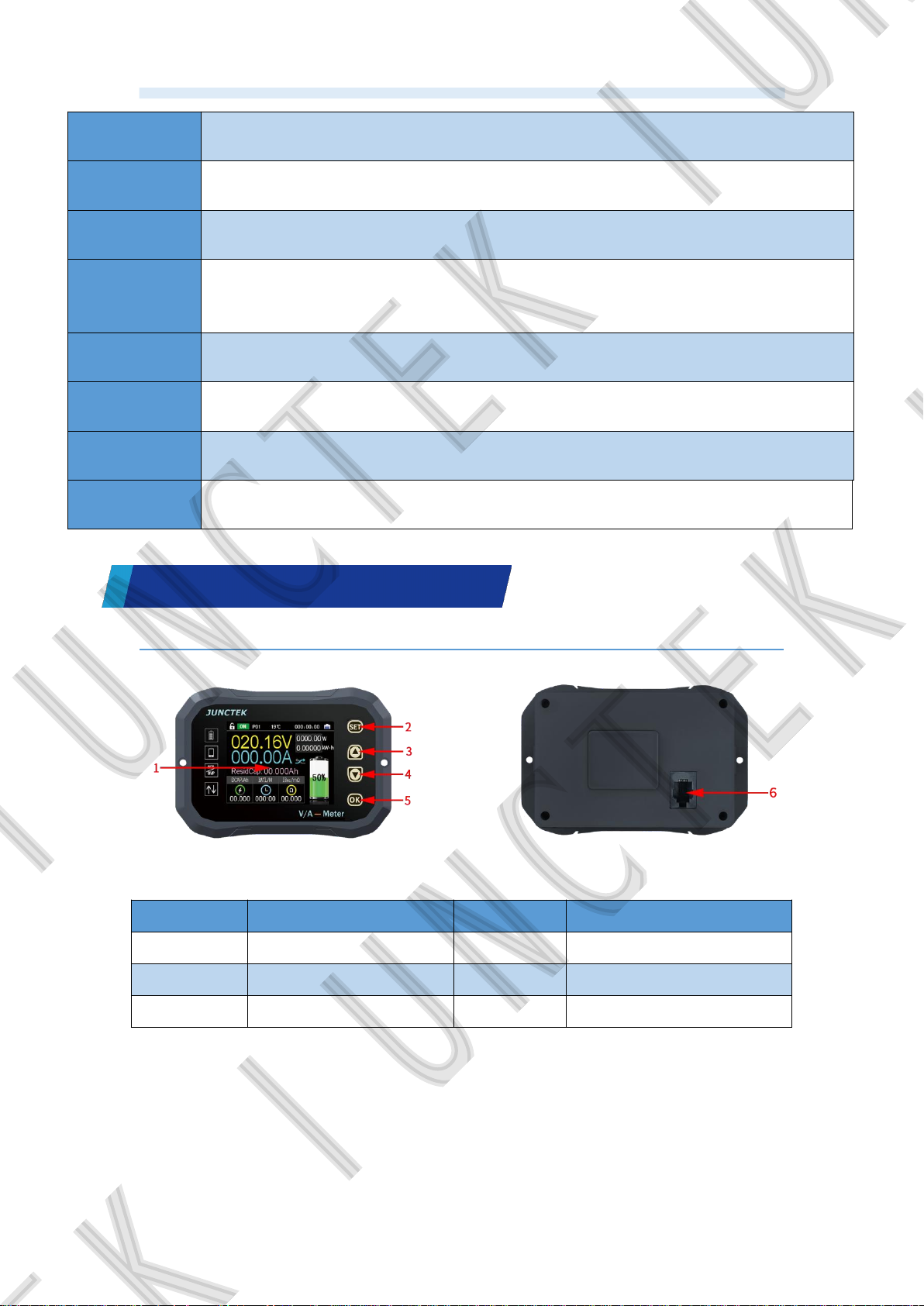
current
protection
Over voltage
protection
Under voltage
protection
External over
temperature
protection
Protection
recovery time
Enter standby
time
Delay time
setting
Communication
address
Hangzhou Junce Instruments Co., Ltd.
0~120V
0~120V
0-120℃
0-99s
0-60s/Auto(I=0 and time>20s)
0-99S
There are 99 P01-P99, P00 is the broadcast address
Chapter
Meter Introduction
Ⅱ
1.Introduction of display module
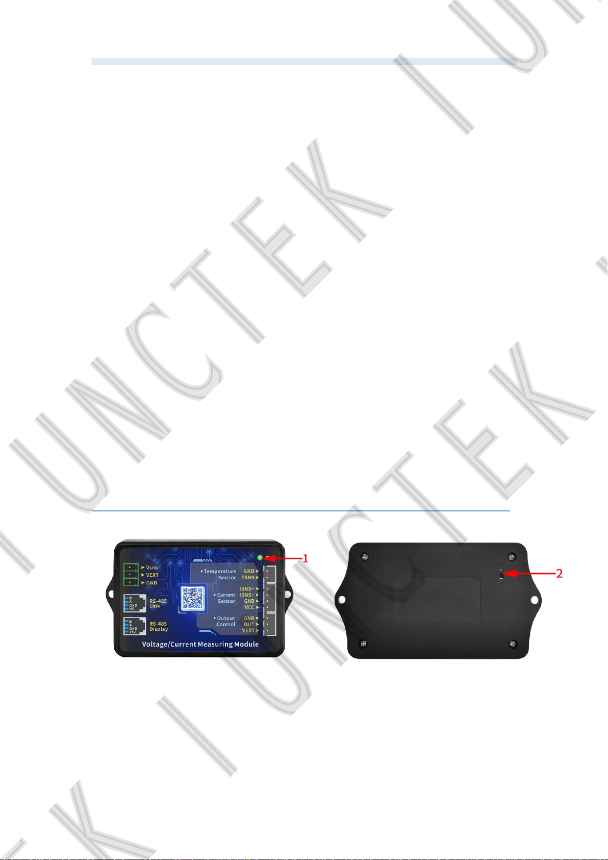
Figure 2-1-1 KG-F series display module diagram
Table 2-1-1 KG-F series display module diagram instructions
Item Description Item Description
1 LCD screen 4 【▼】button
2 【
3 【▲】
SET】button
button
5 【OK】
6 Wiring port
button
(1).LCD screen
The 2.4-inch TFT color LCD screen displays the current function menu
and parameter settings.
(2).【SET】button
6
Page 11
Hangzhou Junce Instruments Co., Ltd.
Shortly pressing the
【
SET
button can quickly switch to the setting
】
interface.
In the main interface, press and hold the【SET】button can select the
address and use【▲
】【▼】
to quickly adjust the address.
(3).【▲】button
When setting parameters,【▲】button is used to change the parameters.
When setting the system,【▲】button is used to select the corresponding
system setting.
(4).【▼】button
When setting parameters,【▼】button is used to change the parameters.
When setting the system,【▼】button is used to select the corresponding
system setting.
In the main interface, press and hold the【▼】button will jump out the
“Clear data” pop-up window to confirm or cancel clear data.
(5).【OK】button
In the main interface, shortly pressing the【OK】button can control on or
off of output status and data record.
Pressing and hold the
【
OK
button can quickly lock or unlock the
】
buttons.
(6).Wiring port
The wiring port is used to connect to the measuring module.
2.Introduction of the measuring module
7
Page 12
Hangzhou Junce Instruments Co., Ltd.
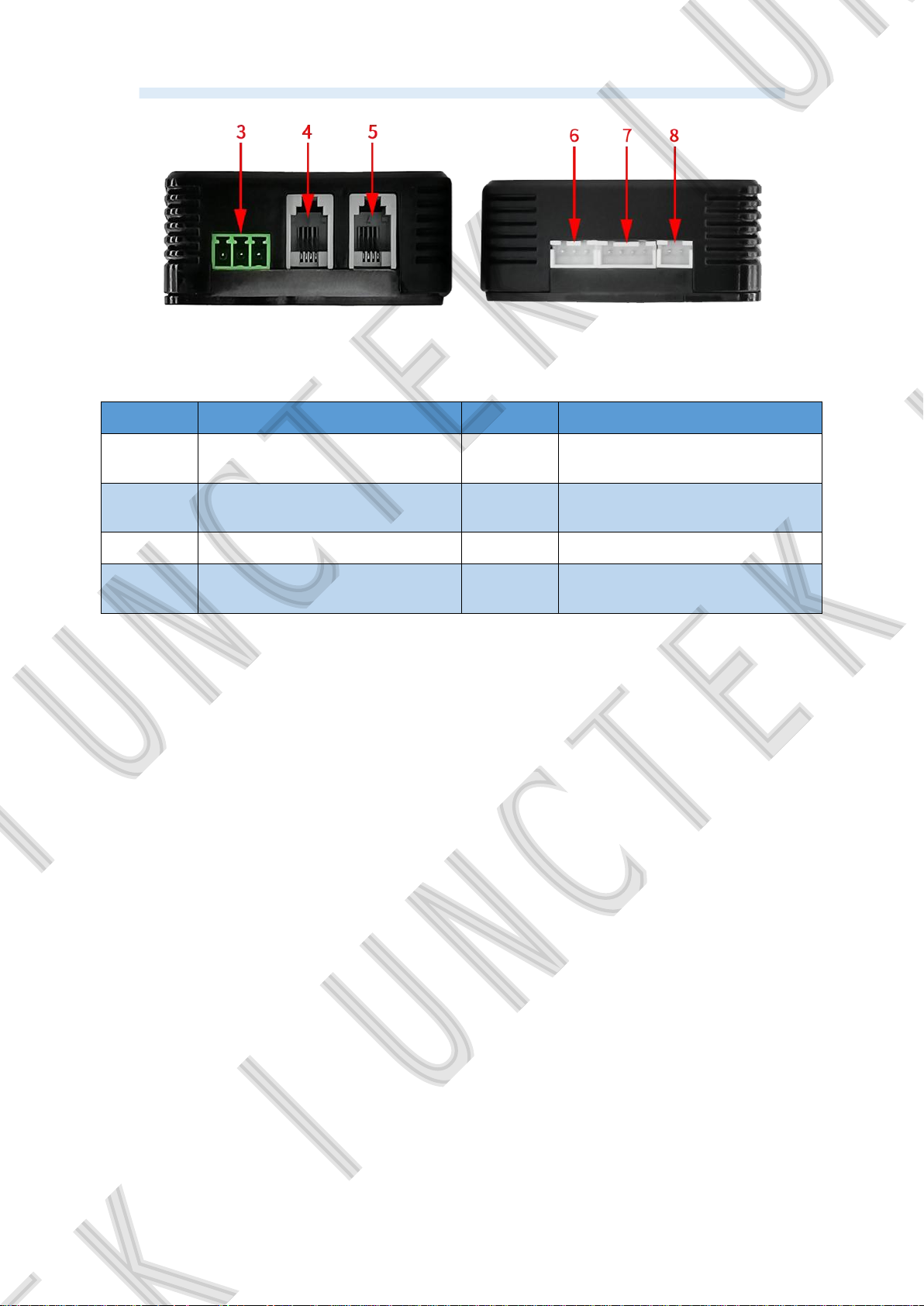
Figure 2-2-1 KG-F series measuring module diagram
Table 2-2-1 Instructions diagram of the KG-F series measuring module
Item Description Item Description
1 Indicator light 5
2 2wires&3wires switch 6
485 communication
display interface
Relay output
control interface
3 Power supply interface 7 Sampler interface
4
485 communication
connection interface
8
External temperature
measurement interface
(1). Indicator light
The blinking of the indicator light indicates the working state, and the slow
flashing indicates that the power supply is normal and the measurement is
under normal operation.
(2). 2-wire 3-wire power supply switch selection
The switch can be selected from external power supply or self-powered,
when the switch is moved up to 2W, it is suitable for self-power supply, and the
voltage measurement range is 10-120V, when the switch is moved down to 3W,
it is suitable for external power supply, and the external power supply voltage
range is 10- 80V, the voltage measurement range is 0-120V.
(3). Power supply interface
There are three power supply interfaces, the battery positive interface:
Vsns, the external power supply positive interface: VEXT, and the battery and
external power supply negative interface: GND.
(4). 485 communication connection interface
The interface used to connect to the computer, and it can also be
connected to another measuring module to realize multi-computer
communication. The internal sequence from left to right is: B, A, GND, NC.
8
Page 13
Hangzhou Junce Instruments Co., Ltd.
(5). 485 communication display interface
Used to connect with the display module, when the measuring module has
power supply, the communication interface is live. The internal sequence from
left to right is: B, A, GND, +5V.
(6). Relay output control interface
The relay output control interface can be used with relays. The internal
sequence from left to right is: GND, OUT, VEXT.
(7). The Sampler interface
Used to connect with the sampler for current detection. The internal
sequence from left to right is: VCC, GND, ISNS+, ISNS-.
(8). External temperature measurement interface
Used to connect with a temperature sensor to measure the external
temperature. The internal sequence from left to right is: TSNS, GND.
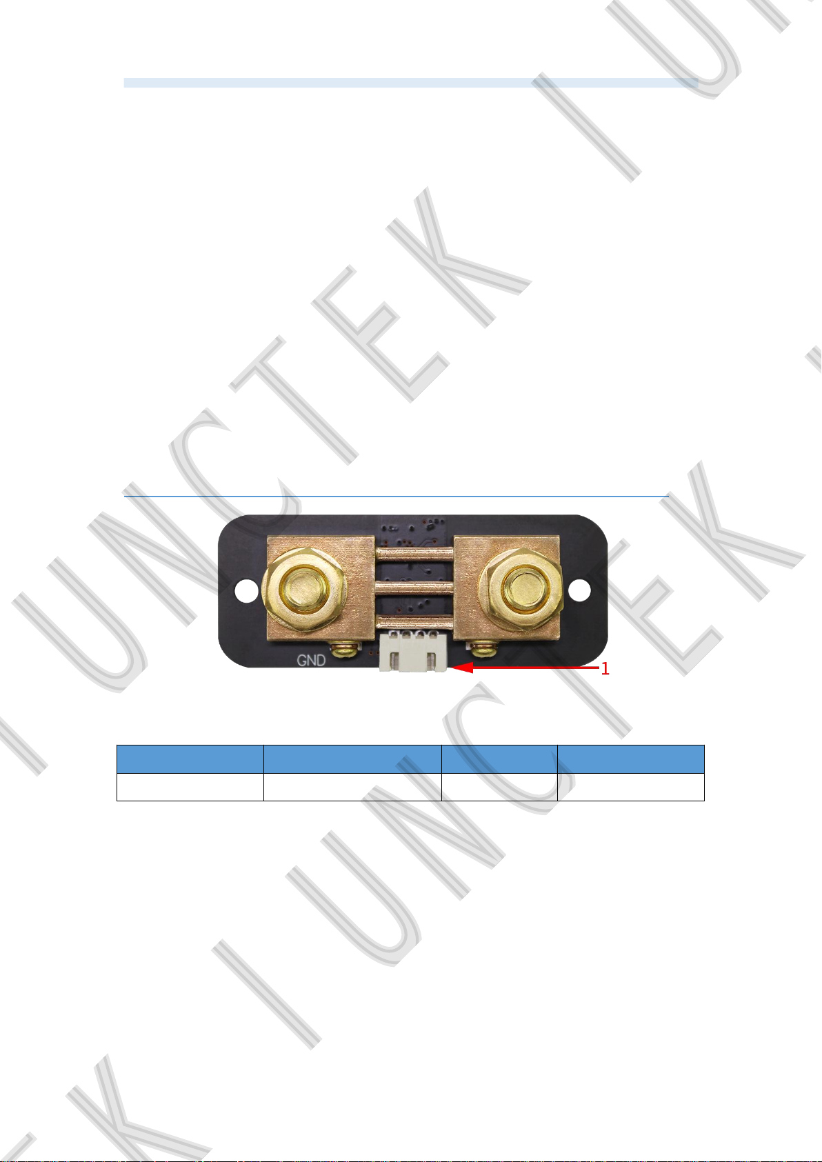
3.Introduction of the Sampler
Figure 2-4-1 KG-F series of the Sampler diagram
Table 2-4-1 KG-F series of the Sampler diagram instructions
Item Description Item Description
1 The Sampler interface
The Sampler interface
Connect to the Sampler interface of the measuring module for current
measurement.
9
Page 14
Hangzhou Junce Instruments Co., Ltd.
4.Introduction of the display interface
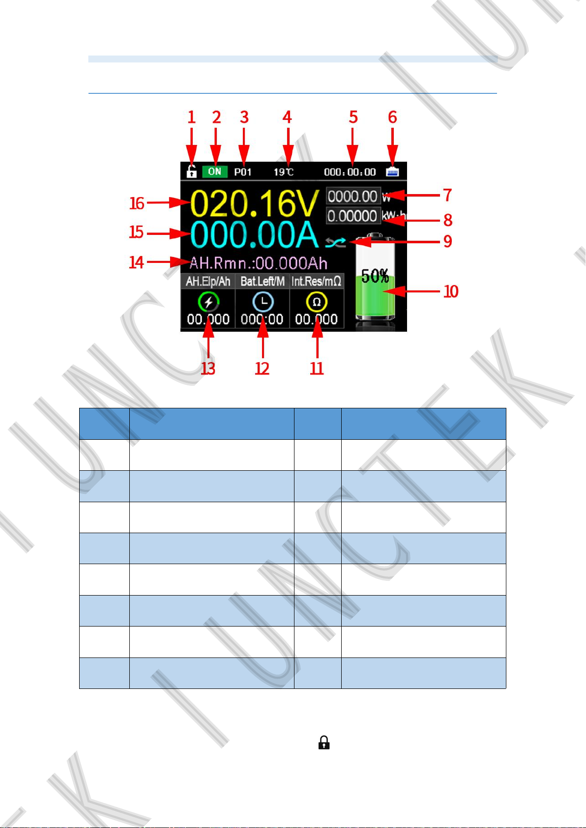
Figure 2-5-1 KG-F series display interface diagram
Table 2-5-1 KG-F series display interface diagram instructions
Item Description Item Description
1 Key lock status 9 Current direction
2
Output status and
data record
10 Battery remaining capacity
3 Communication address 11 Battery internal resistance
4 External temperature 12 Battery life
5 Running time 13 Elapsed AH value
6
Communication
signal indication
14 Remaining AH value
7 Power 15 Measured current value
8 Elapsed electric energy 16 Measured voltage value
(1). Key lock status
The state in the figure indicates that the button can be operated. After
pressing and holding the 【OK 】 button, is displayed ,which means the
10
Page 15

Hangzhou Junce Instruments Co., Ltd.
button is locked.
(2). Output status and data record
Shortly press the【OK】button to control the output status and data record
on or off.
(3). Communication address
The communication address range is P00-P99. P00 is the broadcast
address, used for multi-machine communication, P01 represents that the
current communication address is P01, and view the data of P01 address.
(4). External temperature
It displays the ambient temperature. The current display is 19°C, which
means that the temperature of the environment where the external sensor is
located is 19°C.
(5). Running time
It represents the cumulative value of a single running time.
(6). Communication signal indication
The current graph means that the display module and the measuring
module are connected properly. When there is a red × in the graph, it means
that the communication is interrupted, and the address needs to be switched
or further checked.
(7). Power
It measures the current power value, the unit is W.
(8). Elapsed electric energy
Represents the actual accumulated charging electric energy during the
operation time, unit: KW. h.
(9). Current direction
It represents the direction of current passing through the Sampler. The
current icon can also indicate that the battery is in a discharged state.
(10). Battery remaining capacity
The remaining capacity of the battery is highlighted more intuitively with
graphics, where the 50% value means that the remaining AH. value of the
battery accounts for 50% of the preset battery AH. value. In the main interface,
when the remaining capacity percentage is less than or equal to 20%, the
graph of remaining AH value is red, when remaining AH value percentage is
greater than 20%, the graph of remaining AH value is green.
11
Page 16
Hangzhou Junce Instruments Co., Ltd.
(11).Battery internal resistance (estimated)
It indicates the resistance value of the current battery internal resistance.
(12). Battery left
According to the charge and discharge current and capacity, calculate the
battery left and charging time.
(13). Elapsed AH value
Indicates the cumulative discharge capacity during this operation period.
(14). Remaining AH value
Indicates the remaining capacity of the battery after charging and
discharging. The remaining capacity=preset battery capacity * capacity
percentage.
(15). Measured current value
It represents the actual current value through the Sampler.
(16). Measured voltage value
It represents the voltage value of the voltage measurement interface in the
power supply interface.
ChapterⅢBasic Operation of the Meter
1.System settings
System settings Video: https://youtu.be/oLLRZae82uU
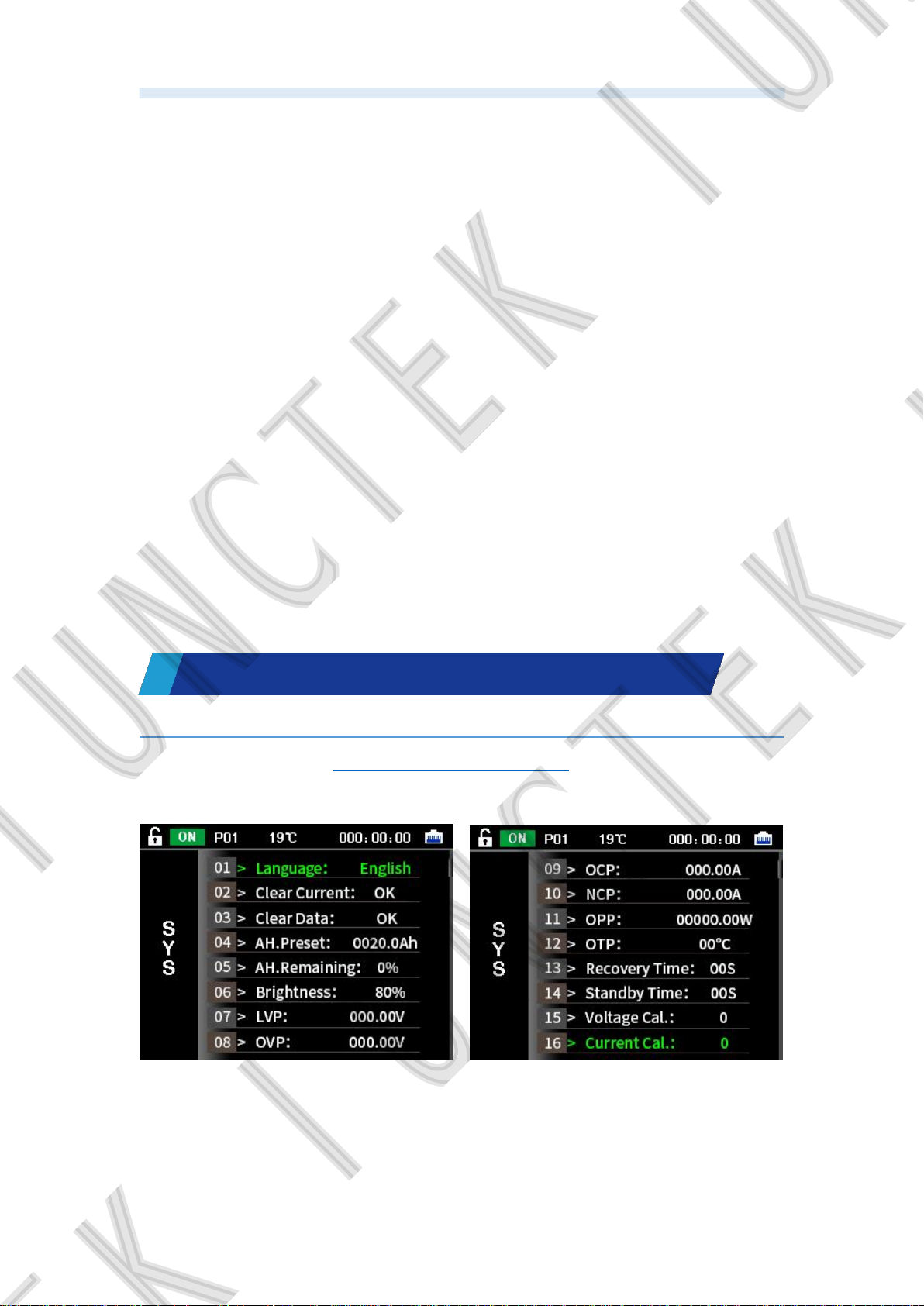
In the main interface, short press the 【SET 】 button to enter the system
setting interface. As shown in Figures 3-1-1 to 3-1-3 below.
Figure 3-1-1 System Setting 01 Figure 3-1-2 System Setting 02
12
Page 17
Hangzhou Junce Instruments Co., Ltd.
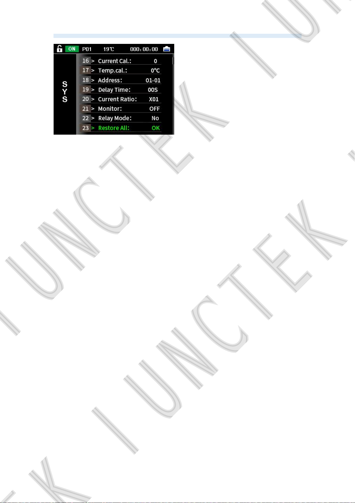
Figure 3-1-3 System Setting 03
(1). Language selection
When the “language” selection is green, you can select the language,
short press the【OK】button, the cursor selects Chinese, press the【▲】【▼
button to switch, there are two language modes, Chinese and English, then
short press the【OK】button after confirming.
】
(2). Set current to zero
In the system setting interface, press the【▲
】 【▼】
button to switch to
“Set current to zero”, short press the【OK】button and the “Set current to zero”
window will pop up, and you can choose to confirm or cancel “set current to
zero” by pressing the【▲
】【▼】
buttons , When the cursor is selected to
confirm, short press the【OK】button, if it displays “Completed” , that means
setting current to zero is completed, and the current will becomes 0A.
Precautions for the first startup and / or after restoring factory
settings:
When the customer starts the meter for the first time or restores the
factory settings, the display will have a small current deviation under
normal circumstances when the meter is not connected to the load. At
this time, the charging state arrow and the discharging state arrow will
jump back and forth, which means that the meter is being calibrated
automatically. This phenomenon will last about 30 seconds, and then the
current will return to zero automatically. At this time, we need to press
the key for a long time to confirm that the current returns to zero, so that
the meter can remember the zero state, and the zero current will not jump
again no matter whether the machine is switched on or off or restarted.
(3). Clear accumulated data
In the system setting interface, press the【▲
】【▼】
buttons can switch
to the “Clear Data”. Short press the【OK】button will jump out the “Clear data”
pop-up window, and then you can press【▲】【▼】buttons to confirm or cancel
clear data. When the cursor is selected to “OK”, short press the【OK】button, if
it displays “Completed”, that meas the data is cleared. Time, watt-hour, and
13
Page 18

Hangzhou Junce Instruments Co., Ltd.
elapsed AH value are cleared at this time, but the measuring is not affected.
(4). Preset battery AH. value
In the system setting interface, pressing the【▲
】 【▼】
buttons can
switch to the “AH. preset”. Short press the【OK】button, the cursor will select
the value, and it can be changed by pressing the【▲】【▼】buttons. Pressing
the【OK】button can switch the cursor position, from the smallest digit to the
highest digit. At the highest position, press the【OK】button again to confirm
and save the preset battery AH. value.
Before using the battery for the first time, you need to set the
effective capacity of the battery and the current remaining power
percentage correctly. If the effective capacity of the battery is unknown
or the current remaining capacity is unknown, the following operation
steps should be followed:
a. Empty the battery pack or put it until you don't want to discharge,
at this time, the battery power is the default 0 power.
b. Enter the preset battery capacity setting in the system settings,
and set the capacity value as large as possible (for example, set the
estimated value 20Ah to 30Ah).
c. Set the remaining capacity percentage to 0%, and then charge the
battery pack.
d. After the battery is fully charged, check the remaining capacity
value displayed on the screen, and set this value to the preset battery
capacity.
(5). Percentage of remaining AH value
In the system setting interface, pressing the【▲】【▼】buttons can switch
to the “AH. remaining”. Short press the【OK】button, the cursor will select the
value, and it can be changed by pressing the【▲
【OK】
button again to confirm that the set remaining AH value accounts for the
】 【▼】
buttons. Press the
preset battery AH value. The remaining AH value can be set according to
actual usage. And the percentage of remaining AH value is continuously
adjustable from 0% to 100%.
In the main interface, when the percentage of remaining AH value is less
than or equal to 20%, the graph of remaining AH value displays red, when the
percentage of remaining AH value is greater than 20%, the graph of remaining
AH value displays green.
After using or replacing the battery for the first time, the capacity value
displayed by the cooulometer is not the actual value of the battery, and
capacity setting is required.
Suggestion: Set 100% for full charge and 0% for discharge, which is more
accurate.
14
Page 19

Hangzhou Junce Instruments Co., Ltd.
(6). Screen brightness
In the system setting interface, press the【▲
】【▼】
buttons can switch
to the “Brightness”. Short press the【OK】button, the cursor will select the
value, and it can be changed by pressing the【▲
【OK】
button again to confirm the screen brightness. The screen brightness is
】 【▼】
buttons. Press the
continuously adjustable from 1% to 100%.
(7). Under-voltage protection
In the system setting interface, press the【▲
】【▼】
buttons can switch
to the “LVP”. Short press the【OK】button, the cursor will select the value,
and it can be changed by pressing the【▲
】【▼】
buttons. Press the【OK
】
button can switch the cursor position, from the smallest digit to the highest digit.
At the highest position, press the
【
OK
button again to confirm the set
】
under-voltage protection value.
When the value is 000.00V, the protection function does not start, when
the value is greater than 000.00V, the protection will start. If the current voltage
is less than the set under-voltage protection value, the upper left of the screen
will display LVP, which is in the protection state. Time stops and no more
capacity is calculated.
The protection function needs to purchase the relay (If there is no
relay, please do not set this value.) and install a relay in the circuit before
it can play a protective role in breaking the circuit.
(8). Over-voltage protection
In the system setting interface, pressing the【▲】【▼】buttons can switch
to the “OVP”. Short press the【OK】button, the cursor will select the value,
and it can be changed by pressing the【▲】【▼】buttons. Pressing the【OK
】
button can switch the cursor position, from the smallest digit to the highest digit.
At the highest position, press the
【
OK
button again to confirm the set
】
over-voltage protection value.
When the value is 000.00V, the protection function does not start, when
the value is greater than 000.00V, the protection will start. If the current voltage
is greater than the set over-voltage protection value, the upper left of the
screen will display OVP, which is in the protection state. Time stops and no
more capacity is calculated.
The protection function needs to purchase the relay (If there is no
relay, please do not set this value.) and install a relay in the circuit before
it can play a protective role in breaking the circuit.
(9). Positive over-current protection
In the system setting interface, pressing the【▲
】【▼】
button to switch
to the discharge over current protection setting. Short press the【OK】button,
the cursor will select the value, and it can be changed by pressing the【▲
【▼】
buttons. Pressing the【OK】button can switch the cursor position, from
】
15
Page 20

Hangzhou Junce Instruments Co., Ltd.
the smallest digit to the highest digit, at the highest position, press the【OK
】
button again to confirm the discharge over current protection.
When the value is 000.00V, the protection function does not start, when
the value is greater than 000.00V, the protection will start. If the current
discharge current is greater than the set discharge over-current protection
value, OCP will be displayed on the upper left of the screen, which is in the
protection state. Time stops and no more capacity is calculated.
The protection function needs to purchase the relay (If there is no
relay, please do not set this value.) and install a relay in the circuit before
it can play a protective role in breaking the circuit.
(10). Negative over-current protection
In the system setting interface, press the【▲
】【▼】
setting of discharge over-current protection. After briefly pressing the【OK
key, the cursor selects the value,and it can be changed by pressing the【▲
【▼】
buttons. Pressing the【OK】button can switch the cursor position, from
the smallest digit to the highest digit, at the highest position, press the【OK
key to switch to the
】
】
】
button again to confirm the set charge over-current protection.
When the value is 000.00A, the protection function will not be started. If
the value is greater than 000.00A, the protection function will be started. If the
charging current is greater than the set charging over-current protection value,
NCP will be displayed at the top left of the screen, which is in the protection
state. Time stops and no more capacity is calculated.
The protection function needs to purchase the relay (If there is no
relay, please do not set this value.) and install a relay in the circuit before
it can play a protective role in breaking the circuit.
(11). Over power protection
In the system setting interface, pressing the【▲】【▼】buttons can switch
to the “OPP”. Short press the【OK】button, the cursor will select the value,
and it can be changed by pressing the【▲】【▼】buttons. Pressing the【OK
button can switch the cursor position from the smallest digit to the highest digit.
At the highest position, press the【OK】button again to confirm the set over
power protection value.
When the value is 00000.00W, the protection function does not start,
when the value is greater than 00000.00W, the protection will start. If the
current power is greater than the set over power protection value, the upper
left of the screen will display OPP, which is in the protection state.Time stops
and no more capacity is calculated.
The protection function needs to purchase the relay (If there is no
relay, please do not set this value.) and install a relay in the circuit before
it can play a protective role in breaking the circuit.
(12). Over temperature protection
16
】
Page 21

Hangzhou Junce Instruments Co., Ltd.
In the system setting interface, pressing the【▲】【▼】buttons can switch
to the “OTP”. Short press the【OK】button, the cursor will select the value,
and it can be changed by pressing the【▲
】【▼】
buttons. Press the【OK
button again to confirm the set over temperature protection.
When the value is 00℃, the protection function does not start, when the
value is greater than 00℃, the protection will start. If the current ambient
temperature exceeds the set over-temperature protection value, the upper left
of the screen will display OTP, which is in the protection state. Time stops and
no more capacity is calculated.
The protection function needs to purchase the relay (If there is no
relay, please do not set this value.) and install a relay in the circuit before
it can play a protective role in breaking the circuit.
(13). Reverting time protection
In the system setting interface, pressing the【▲】【▼】buttons can switch
to the “Revert time”. Short press the【OK】button, the cursor will select the
value, and it can be changed by pressing the【▲
【OK】
button again to confirm the reverting time protection.
】 【▼】
When the value is 00s, the protection status will continue until the【OK
buttons. Press the
】
button is pressed in the main interface to implement the protection status. If the
value is greater than 00s, for example, the protection recovery time is set to 5s,
which means 5 seconds after the value returns to the normal value, the
protection state is automatically canceled, the circuit is closed and work
begins.
】
(14). Enter standby time
In the system setting interface, pressing the【▲】【▼】buttons can switch
to the “Standby Time”. Short press the【OK】button, the cursor will select the
value, and it can be changed by pressing the【▲
【OK】
button again to confirm the set standby time.
】 【▼】
buttons. Press the
0 is changed to normally on, 1-60s indicates how long the screen will be
off without operation (no matter whether there is current or not, the screen will
be off, press any key to wake up the screen); It automatically indicates that the
current is 0 and lasts for 20 seconds, and the screen turns off. Once there is
current, the screen turns on immediately.
(15). Voltage calibration
In the system setting interface, press the【▲
】【▼】
buttons can switch
to the “Voltage Cal.”. Short press the【OK】button, the cursor will select the
value and it can be changed by pressing the【▲
【
OK
button again to confirm the set voltage calibration. The voltage
】
】 【▼】
buttons. Press the
fine-tuning calibration can be performed online. The default voltage calibration
is 0, and the maximum voltage calibration range is±10%.
17
Page 22

Hangzhou Junce Instruments Co., Ltd.
(16). Current calibration
In the system setting interface, pressing the【▲】【▼】buttons can switch
to the “Current Cal.”. Short press the【OK】button, the cursor will select the
value and it can be changed by pressing the【▲
【
OK
button again to confirm the set current calibration. The current
】
】 【▼】
buttons. Press the
fine-tuning calibration can be performed online. The default current calibration
is 0, and the maximum current calibration range is
±
25%.
(17). Temperature calibration
In the system setting interface, pressing the【▲】【▼】buttons can switch
to the “Temp. Cal.”. Short press the【OK】button, the cursor will select the
value and it can be changed by pressing the【▲
【
OK
button again to confirm the set temperature calibration. The
】
】 【▼】
buttons. Press the
temperature fine-tuning calibration can be performed online. The default
temperature calibration is
0℃
.
(18). Set address
In the system setting interface, press the【▲
】【▼】
button to switch to
the address setting, short press the【OK】button and select the value with the
cursor, press the【▲
】【▼】
button to change the communication address,
Press the【OK】button to switch from the preset communication address to the
current communication address, and press the【OK】button again to confirm
the set address.
Example: As shown in Figure 3-1-3, the set address is 03-01, 01
represents the preset communication address, the preset communication
address range is 01-99, 03 represents the current measuring module
communication address, and the current communication address range is
00-99 , 00 represents the broadcast address. If we don’t know the current
communication address of the measuring module, we can set the current
communication address to 00, and set the default communication address to
the desired address 03 (for example: 00-03). After setting, press
【OK】
to
complete the setting. At this time, the current communication address of the
measuring module is 03, and the meter can communicate normally. (Use the
broadcast address with caution in multi-machine communication)
When multiple measuring modules are connected, the current
communication address can be switched to control the measuring module
corresponding to the address. At 00, multiple measuring modules can be
controlled at the same time.
(19). Set delay time
In the system setting interface, pressing the【▲】【▼】buttons can switch
to the “Delay Time”. Short press the【OK】button, the cursor will select the
value and it can be changed by pressing the【▲
【OK】
button again to confirm the set delay time.
18
】 【▼】
buttons. Press the
Page 23

Hangzhou Junce Instruments Co., Ltd.
When the delay time is set to 00s and the measured value exceeds the
set protection value, the meter will immediately enter the protection state,
when the delay time is greater than 00s, for example, it is set to 5s, when the
measured value exceeds the set protection value, the meter enters the
protection state after 5s.
(20). Current ratio (this function is only available for KG-H series Hall sensor
version)
In the system setting interface, press the【▲
】【▼】
button to switch to the
current ratio setting, short press the【OK】button and the cursor selects the
value, press the【▲
【OK】
button again to confirm the set current ratio. The default is X01.
】【▼】
button to change the value, and then press the
Example: When the wire of the Hall sensor is wound 10 times, the current
multiplier is set to X01, the measured current value is displayed as the total
current passing through the Hall sensor 10 times, the current multiplier is set to
X10, and the measured current value is displayed as passing The current
value of one turn of the Hall sensor wire. Can be used to measure small
currents.
(21). Monitor function
In the system setting interface, pressing the【▲】【▼】buttons can switch
to the “Monitor function”. Short press the【OK
【▲】 【▼】
buttons to switch on or off. The monitor function must be turned
button and then press the
】
on when using the computer software control. After the monitor function is
turned on, the setting function in the display module can only set the system
language, working screen brightness and enter the standby time (After the
monitoring function is turned on, the display module will not automatically
update the data.).
(22).Relay mode
In the system setting interface, pressing the【▲】【▼】buttons can switch
to the “Relay Mode”. Short press the【OK】button and then press the【▲
【▼】
buttons to switch between “NO” and “NC”.
After the selection is completed, press the【OK】button again to confirm
the type of relay. When using this function, you need to select normally open or
normally closed according to the relay type connected during actual wiring.
(23). Restore factory settings
In the system setting interface, press the【▲
】【▼】
key to switch to
restore the factory settings. After a short press of the【OK】key, the restore
factory settings box will pop up. Through the【▲
】【▼】
key, you can select to
confirm or cancel the restore factory settings. When the cursor is selected to
confirm, press the【OK】key briefly. if the display shows success, the restore
factory settings will be completed.
】
19
Page 24
Hangzhou Junce Instruments Co., Ltd.
2.Wiring method
Wiring instructions video: https://youtu.be/Hjj9fkyuNp0
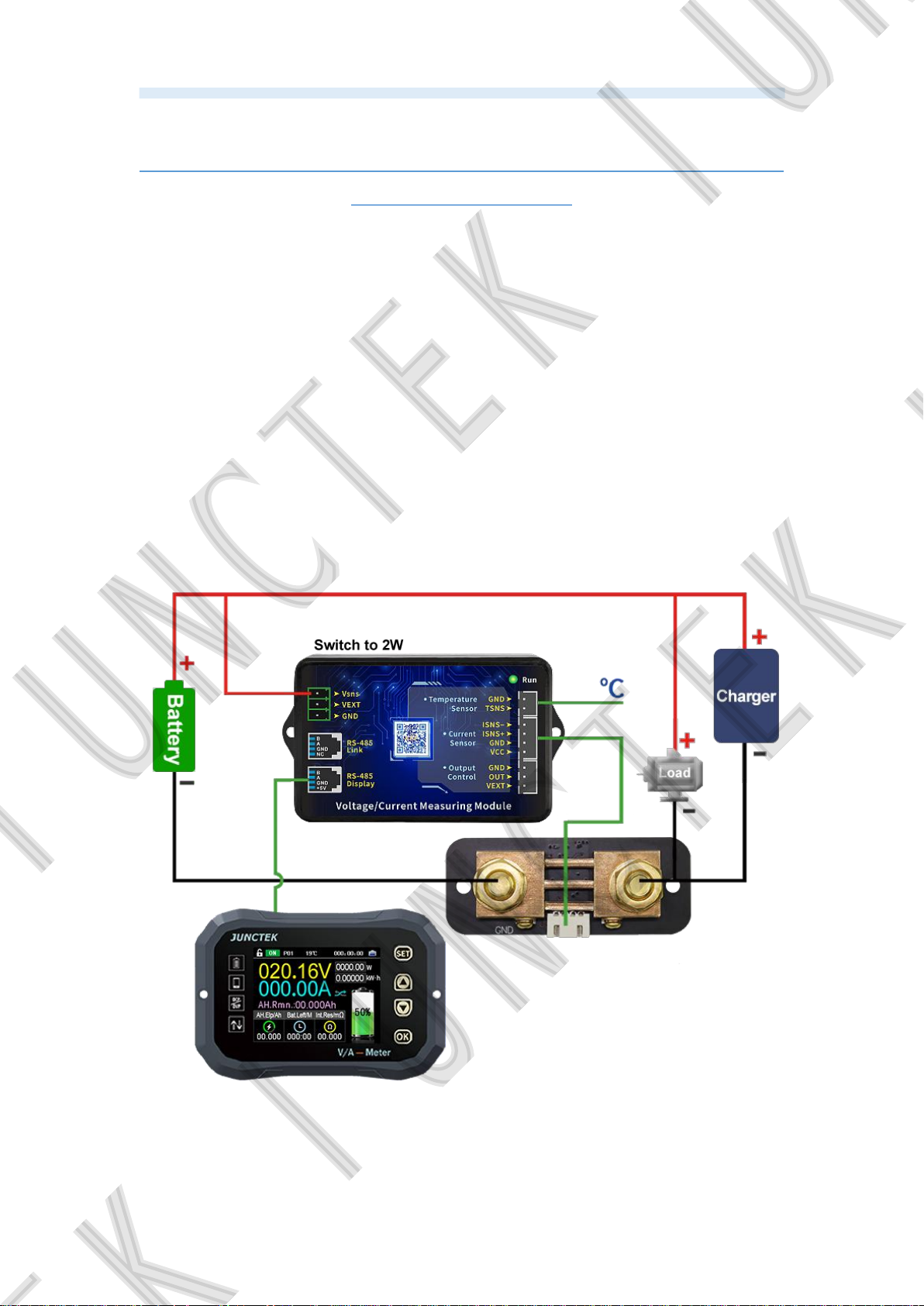
(1). Self-powered wiring method
If the voltage range of the tested battery is between 10-120V during
normal operation,self-powered wiring can be used. First, turn the power supply
selection interface switch to "2W", and then connect the positive terminal of the
battery to the power supply interface "Vsns" , This line does not need to be
particularly thick,13-16AWG wire is fine. Pay attention to the positive and
negative poles of the battery, do not connect the wrong or reverse connection.
The negative pole of the battery is connected to the screw with the battery
“BATT-” on the sampler, and the negative pole of the charger and the negative
pole of the load are connected to another screw of the sampler. It is better to
use a copper nose to connect it firmly. When charging, the current direction
symbol color is red, and the remaining capacity value increases. When
discharging, the color of the current direction symbol is sky blue, and the
remaining capacity value decreases.
Figure 3-3-1 Self-powered wiring diagram
20
Page 25
Hangzhou Junce Instruments Co., Ltd.
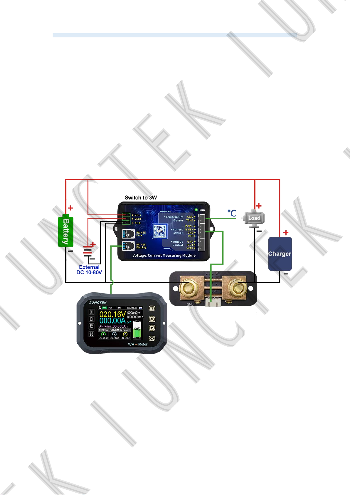
(2). External power supply wiring method
The measuring voltage range of the external power supply is 0-120V.
First, set the power selection interface switch to "3W", connect the positive
pole of the external power supply to the power interface "VEXT", and connect
the negative pole of the external power supply to "GND". When wiring, connect
the positive pole of the battery to the measurement interface "Vsns" in the
power interface. Note that the positive and negative poles of the battery and
the external power supply should not be connected incorrectly or reversed.
The negative pole of the battery is connected to the screw with the battery
“BATT-” on the sampler, and the negative pole of the charger and the negative
pole of the load are connected to the other screw of the sampler together. It is
better to use copper nose to connect firmly. When charging, the current color is
green and the residual capacity value increases. When discharging, the
current color is sky blue and the residual capacity value decreases.
Figure 3-3-2 External power supply wiring diagram
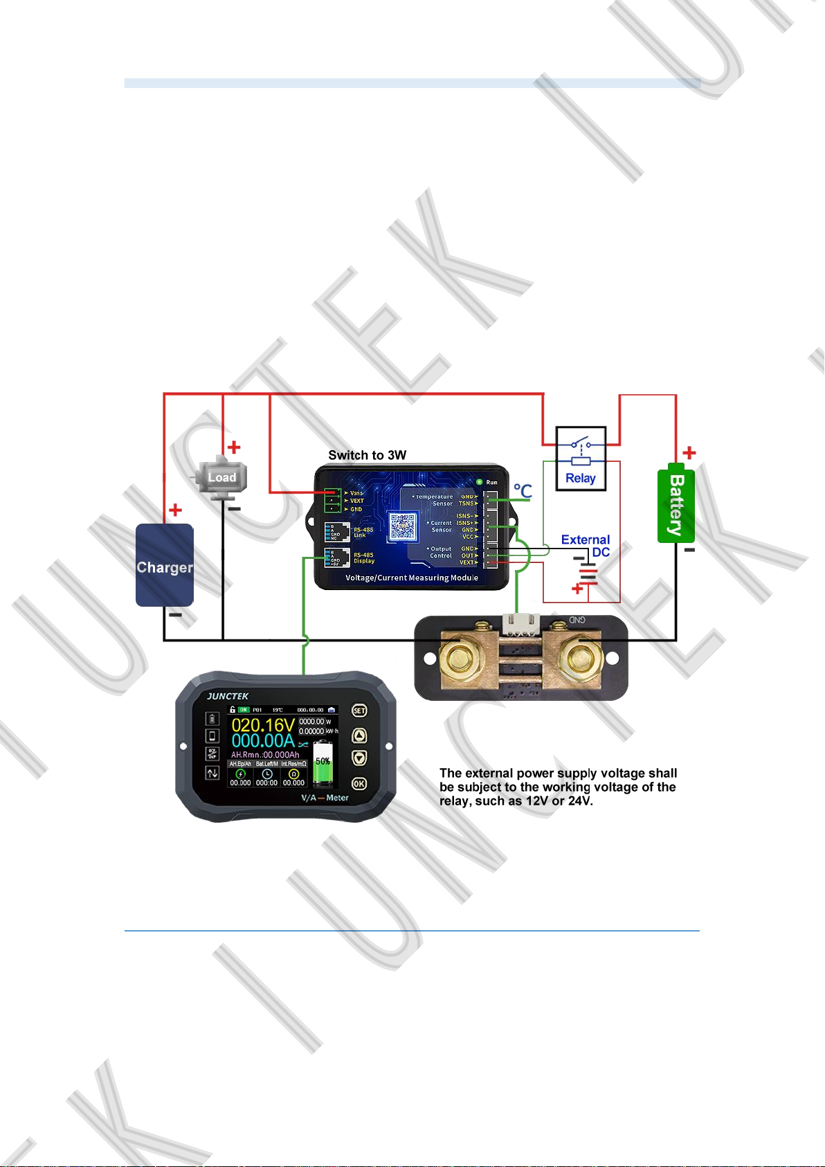
(3). External power supply wiring method(Relay control
)
The working power of the relay is provided by an external power supply. If
the relay is connected, an external power supply with the same working
voltage as the relay should be provided. Connect the control ports of the relay
to the "OUT" and "VEXT" of the measurement module Output Control, connect
the positive pole of the external power supply to the "VEXT" of the Output
Control, and the negative pole of the external power supply to the "GND". Note
21
Page 26
Hangzhou Junce Instruments Co., Ltd.
that the positive and negative poles of the battery and the external power
supply should not be connected wrongly or reversed.
If you want to control the charging or discharging, you should connect the
wiring according to the wiring diagram of external power supply relay in figure
3-3-3. When the relay is closed, the indicator light will be on, and when it is
disconnected, it will be off as a prompt.
The negative pole of the battery is connected to the screw with the battery
"BATT-" on the sampler. The negative pole of the charger and the negative
pole of the load are connected to the other screw of the sampler. It is better to
use a copper nose to connect it firmly. When charging, the current direction
symbol color is red, the remaining capacity value increases. When
discharging, the current direction symbol color is sky blue, and the remaining
capacity value decreases.
Figure 3-3-3 External power supply wiring diagram (Relay control)
3.Communication protocol control
We only provide communication protocol, customers can carry out
secondary development according to communication protocol.
1.Overview
The command line is used as the control command, and the
communication rate is 115200. The PC sends out the command, the meter
22
Page 27
Hangzhou Junce Instruments Co., Ltd.
parses and executes it, and then returns the result to the PC. The different
commands are described below.
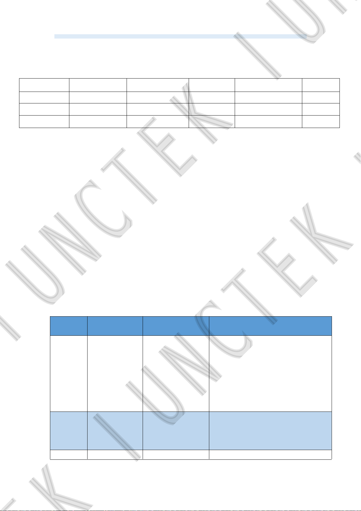
The sending data format is as follows:
Start bit Function code Function No. Connector Address symbol Spacer
: W,R 00~99 = 1-99 ,
Checksums Spacer Data field Spacer Terminator
1-255 , See instructions , <CR><LF>
Explain:
(1) Function code: "W" is the write instruction used to set various parameters,
and "R" is the parameter used by the read instruction to return to the machine.
(2) Function No.: different values represent different parameter settings.
(3) Address symbol: address range is 1-99, 0 is broadcast address.
(4) Checksum: the value of the sum is obtained by adding 1 to the remainder of
255 after the sum of all the numbers after the check sum. If the sum of the
check is taken as 0, it means that it is not verified.
(5) Data field: the data field is equivalent to the number of operations of the
command. For example: W20=12162000, the instruction operands are 2000,
which means that the over voltage protection is set to 20.00V.
(6) Terminator: Each instruction ends with a carriage return + line feed, and
<CR> represents the carriage return in the ASCII character table (hexadecimal
representation is 0x0d). <LF> is the newline character in the ASCII character
table (in hexadecimal notation is 0x0a). The above two methods indicate
carriage return and line feed.
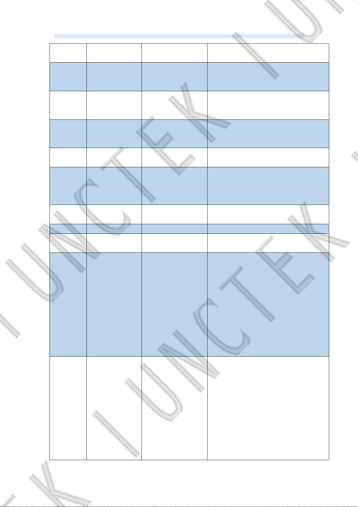
1. W instructions
Function
code
Set up Send command Illustrate
The communication address is set
to 2 (this command should be used
with caution, if you want to use it,
01 Set address :W01=1,3,2,
you must know the current
communication address and the
communication address to be set, it
is recommended to use the mobile
APP to modify)
Turn on output status and data
recording
Turn off output status and data
recording
10
Turn on the
output
:W10=1,2,1,
:W10=1,0,0,
20 Set :W20=1,216,2000, The over-voltage protection value is
23
Page 28
Hangzhou Junce Instruments Co., Ltd.
over-voltage
set to 20.00V.
protection
21
22
23
24
25
26
Set
under-voltage
protection
Set positive
over-current
protection
Set negative
over-current
protection
Set over power
protection
Set over
temperature
protection
Set protection
reverting time
:W21=1,216,2000,
:W22=1,216,2000,
:W23=1,216,2000,
:W24=1,216,2000,
:W25=1,151,150,
:W25=1,211,210,
:W26=1,31,30,
The under-voltage protection value
is set to 20.00V.
The positive over-current protection
value is set to 20A.
The negative over-current
protection value is set to 20A.
The over power protection value is
set to 20W.
The over temperature protection
value is set at 50℃.
The over temperature protection
value is set to 110℃.
The protection reverting time is set
to 30s.
27 Set delay time :W27=1,31,30, The delay time is set to 30s.
28
Set battery
capacity
:W28=1,216,2000,
The battery capacity is set at
200.0Ah.
Set the voltage calibration value to
:W29=1,121,120,
20, and fine-tune to increase the
voltage value.
Set the voltage calibration to a value
29
Voltage
calibration
settings
of -20, and fine-tune to reduce the
voltage value.
(The value only represents the
fine-tuning factor, the greater the
:W29=1,81,80,
absolute value of the value, the
greater the amplitude of the
fine-tuning)
Set the current calibration value to
:W30=1,121,120,
20, and fine-tune to increase the
current value.
Set the current calibration to a value
30
Current
calibration
settings
of -20, and fine-tune to reduce the
current value.
(The value only represents the
fine-tuning factor, the greater the
absolute value of the value, the
:W30=1,81,80,
greater the amplitude of the
fine-tuning)
24
Page 29
Hangzhou Junce Instruments Co., Ltd.
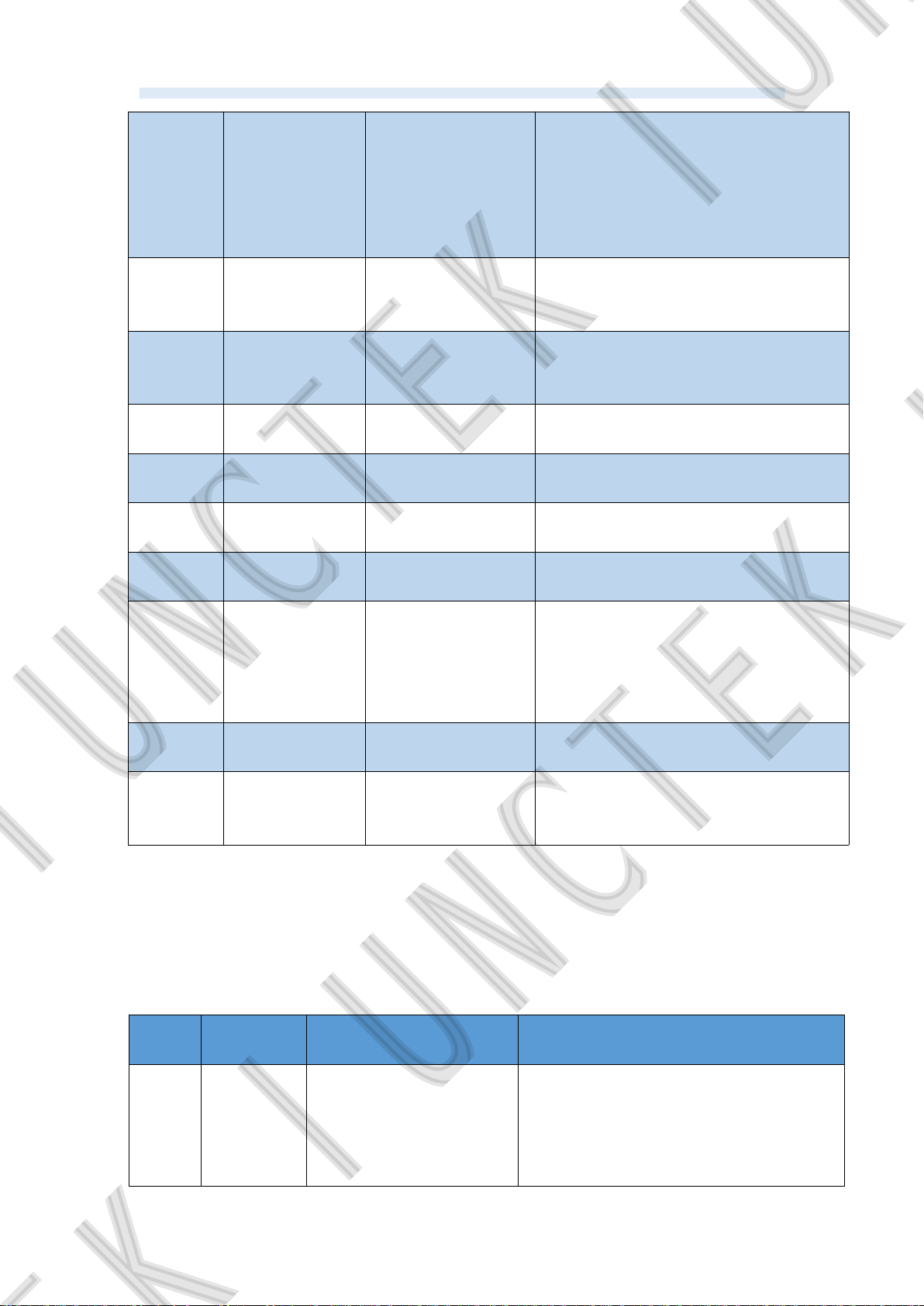
Temperature
31
calibration
settings
Reserved
33
settings
(coming soon)
34 Set relay type
35
36
37
38
Restore
factory settings
Set current
ratio
Setting voltage
curve scale
Setting current
curve scale
Set the
percentage of
60
battery
remaining
capacity
61
Current clear
to zero
Clear
62
accumulated
data
Set the temperature calibration
:W31=1,104,103,
value to 3°C, and the temperature
increases by 3°C.
Set the temperature calibration
:W31=1,99,98,
value to -2°C, and the temperature
decreases by 2°C.
Reserved settings
(coming soon)
:W34=1,2,1,
Reserved settings (coming soon)
Set the relay type to normally
closed.
:W34=1,0,0,
Set the relay type to normally open.
:W35=1,2,1, Perform factory reset
:W36=1,4,3, The current ratio is set to 3.
:W37=1,4,3,
:W38=1,4,3,
The voltage curve scale is set to
03v / Div.
The current curve scale is set to 03v
/ Div.
:W60=1,51,50, 50% of battery capacity remaining
:W61=1,2,1, Perform current clear to zero
:W62=1,2,1, Perform clear accumulated data
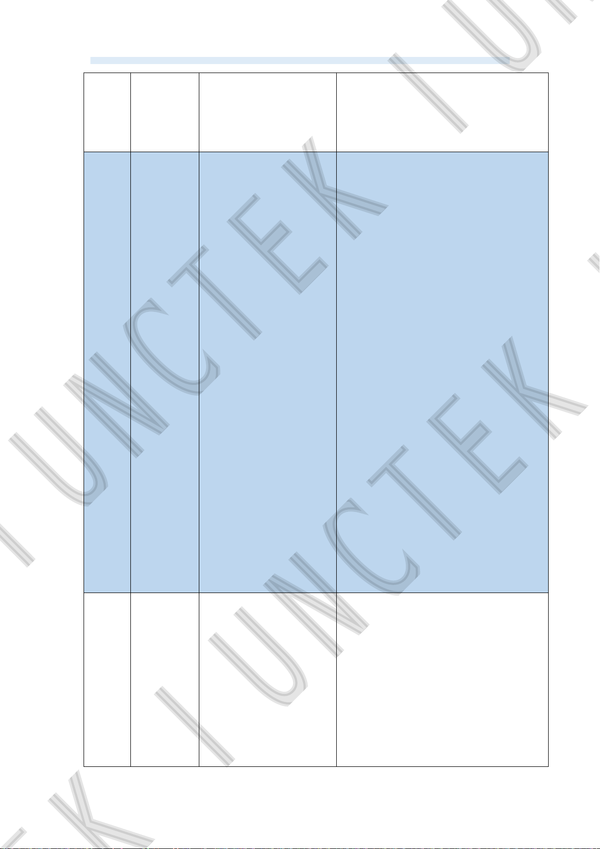
2. R instructions
The R command is a read command, and its command format is basically
the same as the write command format. The description will not be repeated
here. The following is the data returned by the machine, which is just an
example.
Read
Read
basic
machi
ne
inform
PC
sending
Machine return Read instructions
:R00=1,2,1,:r00=1,47,1120,100,10
1,
25
1 represents the communication
address;
47 stands for check sum;
In 1120, the first one represents Hall
sensor (1-hall sensor, 2-shunt
Page 30
Hangzhou Junce Instruments Co., Ltd.
ation sampler), the second one represents
100V, and 20 represents 200A;
100 represents version 1.00;
101 represents the machine serial
number;
2 represents the communication
address;
215 represents the checksum;
2056 represents the voltage of
20.56V;
200 represents current 2.00A;
5408 represents the remaining
battery capacity is 5.408Ah;
4593 means the cumulative capacity
is 4.593Ah;
9437 represents the watt-hour is
Read
all
meas
ured
values
:R50=2,2,
1,
:r50=2,215,2056,200,
5408,4592,9437,14353
,
134,0,0,0,162,30682,
0.09437kw.h;
14353 represents the running time of
14353s;
134 represents the ambient
temperature is 34℃;
0 means the function is pending;
0 means the output status is ON;
(0-ON, 1-OVP, 2-OCP, 3-LVP, 4-NCP,
5-OPP, 6-OTP, 255-OFF)
0 represents the direction of current,
and the current is forward current;
(0-forward, 1-reverse)
162 means battery life is 162
minutes;
30682 represents the internal
resistance of the battery is 306.82m
Ω.
1 represents the communication
address;
211 stands for checksum;
Read
all
setting
s
:R51=1,2,
1,
:r51=1,211,3000,100,2
000,
2000,10000,151,10,7,2
00,
120,90,101,0,0,2,12,13
,
3000 means that the over-voltage
protection is 30.00V;
100 means that the under-voltage
protection is 1.00V;
2000 means that the positive
over-current protection is 20.00A;
2000 represents the negative
over-current protection is -20.00A;
26
Page 31
Hangzhou Junce Instruments Co., Ltd.
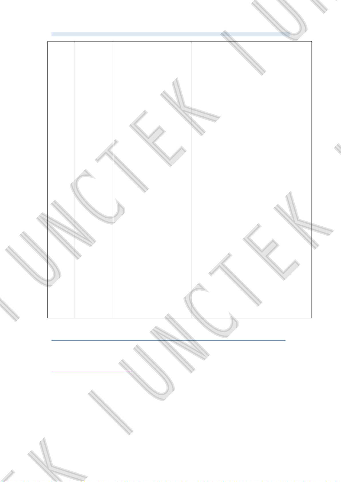
10000 means that the over power
protection is 100.00W;
151 means that the over-temperature
protection is 51℃;
10 means the protection recovery
time is 10s;
7 means the delay time is set to 7s;
200 means that the preset battery
capacity is 20.0Ah;
120 represents the value of the
voltage calibration is 20, and the
voltage fine-tuning increases;
(100 means no fine-tuning)
90 represents the value of the current
calibration is 10, and the current
fine-tuning is reduced;
(100 means no fine-tuning)
101 represents a temperature
calibration increase of 1℃;
(100 means no fine-tuning)
0 stands for reserved settings
(coming soon);
0 represents the relay type is
normally open;
(0-normally open relay, 1-normally
closed relay)
2 represents the current ratio is 2;
12 represents the voltage curve scale
is 12V/div;
13 represents the current curve scale
is 13A/div.
4.Mobile APP control
1. App Instructions (For Android)
Android mobile app installation and operation demonstration video:
https://youtu.be/IFtG6Li8yfk
(1) App download
Google download link:
https://play.google.com/store/apps/details?id=com.juntek.vat
Server download link:
http://68.168.132.244/app/KG.apk
If you cannot download, you can ask customer serviceto obtain the software.
(
27
)
Page 32
Hangzhou Junce Instruments Co., Ltd.
(2) App Software Installation
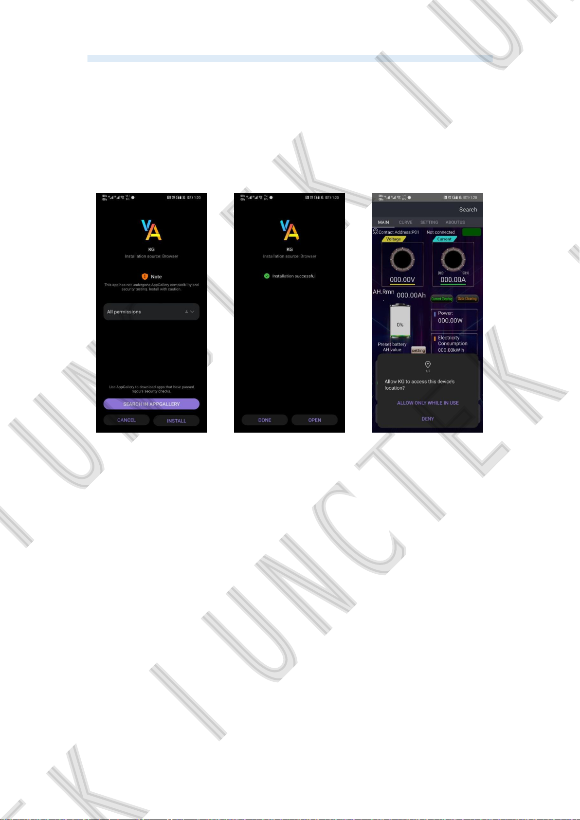
This software only supports Android 5.0 and more advanced systems. It
will apply for location during the installation. Please agree and turn on location
services. The Bluetooth module cannot be plugged or unplugged in a powered
state, which may cause damage. This guide corresponds to software version
1.4.26, and different versions may be slightly different. It is recommended to
upgrade to the latest version for a better experience. The installation steps are
shown in figure 3-5-1 to 3-5-3 below.
Figure 3-5-1
Installation step 1
Figure 3-5-2
Installation step 2
Figure 3-5-3
Installation step 3
(3) Software update
Click the App icon, after the App is started, the system will automatically
detect whether there is a new version of the App in the background, and the
new version will pop up to remind you to update. Apps downloaded from
Google play need to manually detect new versions.
28
Page 33
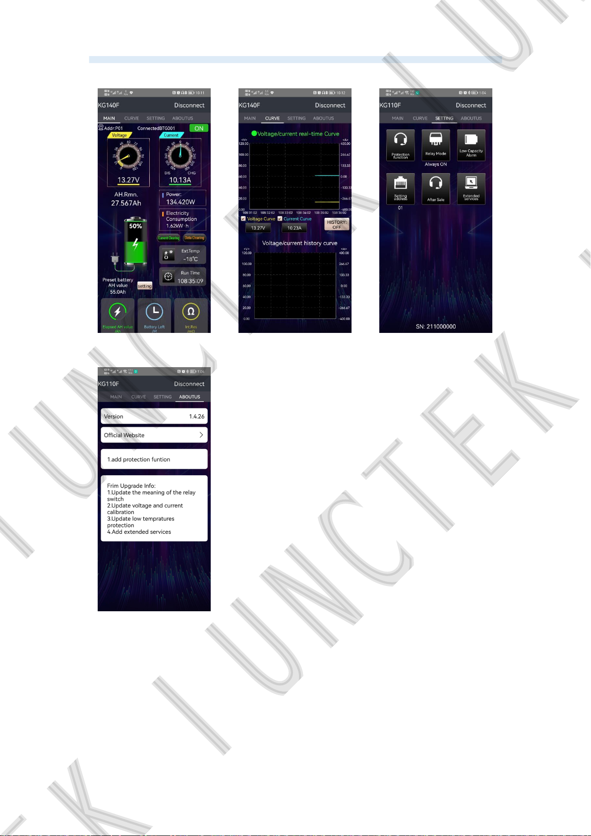
(4) App interface
Hangzhou Junce Instruments Co., Ltd.
Figure 3-5-4 Main
interface
Figure 3-5-7 About us
Figure 3-5-5 Curve
Figure 3-5-6 System
Settings
(5) App operation instructions
Connection
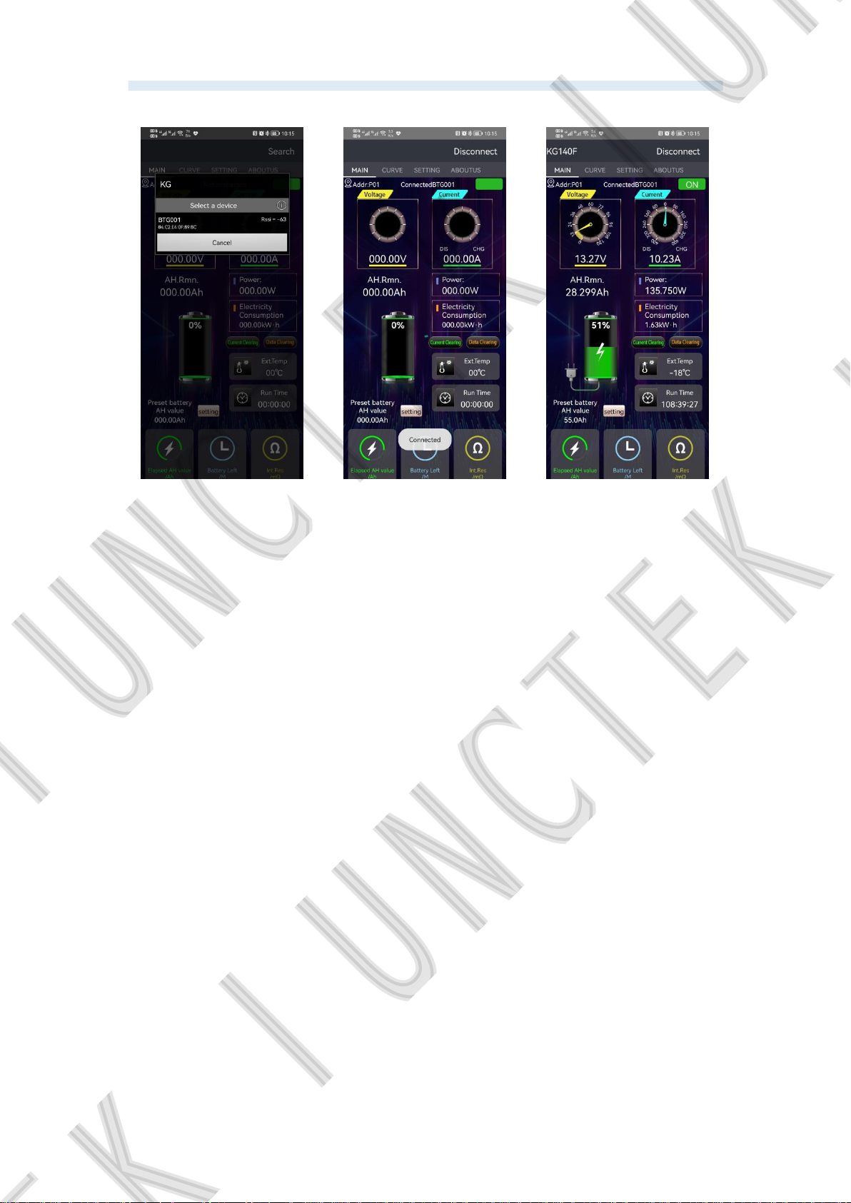
Open the APP on the homepage and click the【Search】in the upper
right corner to search for the corresponding Bluetooth. After clicking the
corresponding Bluetooth, the interface will pop up "Connected", and the
Search
【
in the upper right becomes disconnected, and the meter model
】
appears, indicating that the connection is complete. As shown in Figure 3-5-8,
29
Page 34
Hangzhou Junce Instruments Co., Ltd.
Figure 3-5-9, Figure 3-5-10.
Figure 3-5-8 Connect 1 Figure 3-5-9 Connect 2 Figure 3-5-10 Connect 3
Main interface operation
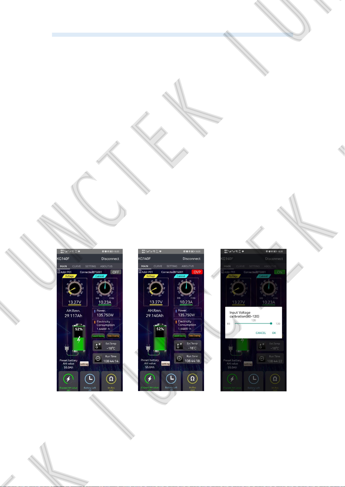
Output state control switch: Click to control the output state, and different
states will be displayed under different protection states, as shown in Figure
3-5-11 and 3-5-12.
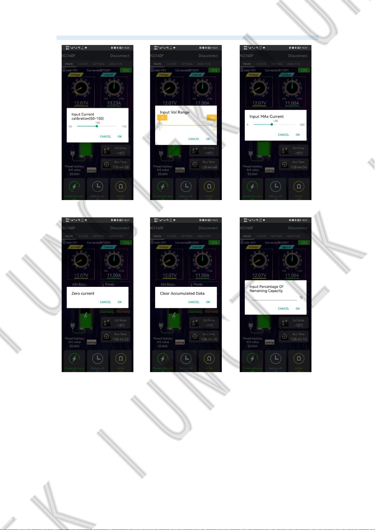
Voltage calibration: Click on the voltage value, "input voltage calibration" will
pop up, enter the corresponding value for fine-tuning, as shown in Figure
3-5-13 below.
Current calibration: Click on the current value, "input current calibration" will
pop up, enter the corresponding value for fine-tuning, as shown in Figure
3-5-14 below.
Voltage range: Click on the voltage dial, the pop-up box "Input voltage range"
will pop out, enter the corresponding value, you can adjust the scale range of
the voltage dial, as shown in Figure 3-5-15 Voltage scale range.
Current scale maximum value: Click on the current scale dial, the pop-up box
"Input the maximum current value" pops out, enter the correct value to adjust
the maximum scale value of the current dial, as shown in Figure 3-5-16
Current scale maximum value.
Zero current: When the load is 0, click the zero current button, the pop-up box
"Zero current" pops out, click OK to memorize the current in this state, as
shown in Figure 3-5-17 Zero current.
30
Page 35
Hangzhou Junce Instruments Co., Ltd.
Clear data: Click the clear data button, the pop-up box "Clear cumulative data "
will pop up, click OK to reset the time, watt-hour, and cumulative capacity, as
shown in Figure 3-5-18 Clear data.
Remaining capacity percentage: Click the battery icon, the pop-up box“Input
percentage of remaining capacity”will pop up, enter the corresponding value
and click OK to complete the modification, as shown in Figure 3-5-19
Remaining capacity percentage.
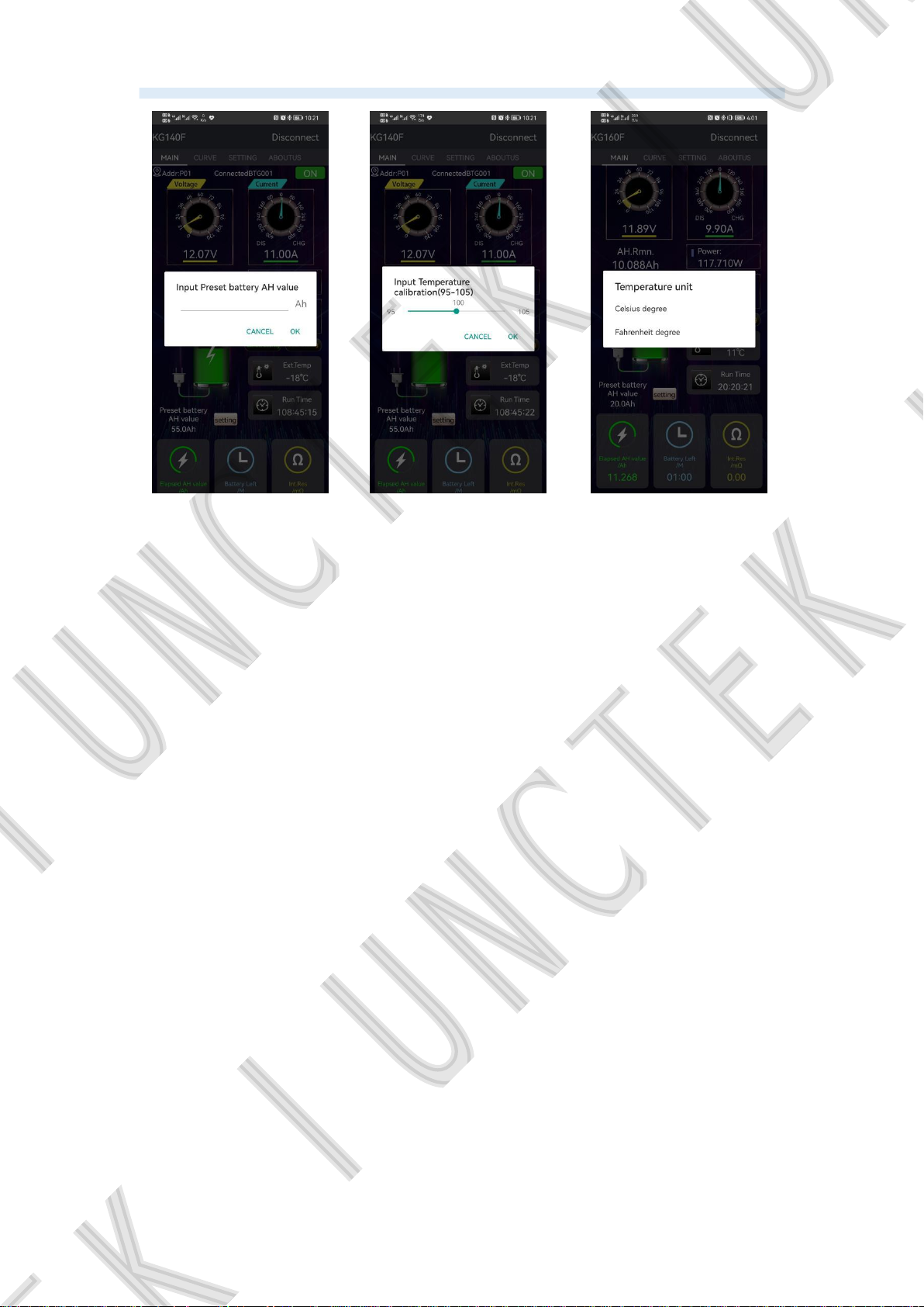
Preset battery capacity: Click the setting button to the right of the preset
battery capacity, the pop-up box "Input preset battery AH value" will pop up,
enter the corresponding value and click OK to complete the modification, as
shown in Figure 3-5-20 Preset battery capacity.
Ambient temperature: Click the ambient temperature icon to pop up the pop-up
box and enter "external temperature calibration", enter the correct value and
click OK to complete the modification, as shown in Figure 3-5-21 ambient
temperature.
Ambient temperature unit switching: Click the ambient temperature value to
pop up the pop-up "Temperature Unit", select Celsius or Fahrenheit, the
default is Celsius. As shown in Figure 3-5-22 temperature unit.
Figure 3-5-11
Output status :Off
Figure 3-5-12
Over-voltage protection
status
31
Figure 3-5-13
Input Voltage calibration
Page 36
Hangzhou Junce Instruments Co., Ltd.
Figure 3-5-14
Input Current calibration
Figure 3-5-17
Zero current
Figure 3-5-15
Voltage Range
Figure 3-5-18
Clear Accumulated
Data
Figure 3-5-16
Input Max Current
Figure3-5-19
Remaining Capacity
Percentage
32
Page 37
Hangzhou Junce Instruments Co., Ltd.
Figure 3-5-20
Input Preset battery AH
value
Figure 3-5-21
Input Temperature
calibration
Figure 3-5-22
Temperature unit
Curve interface operation
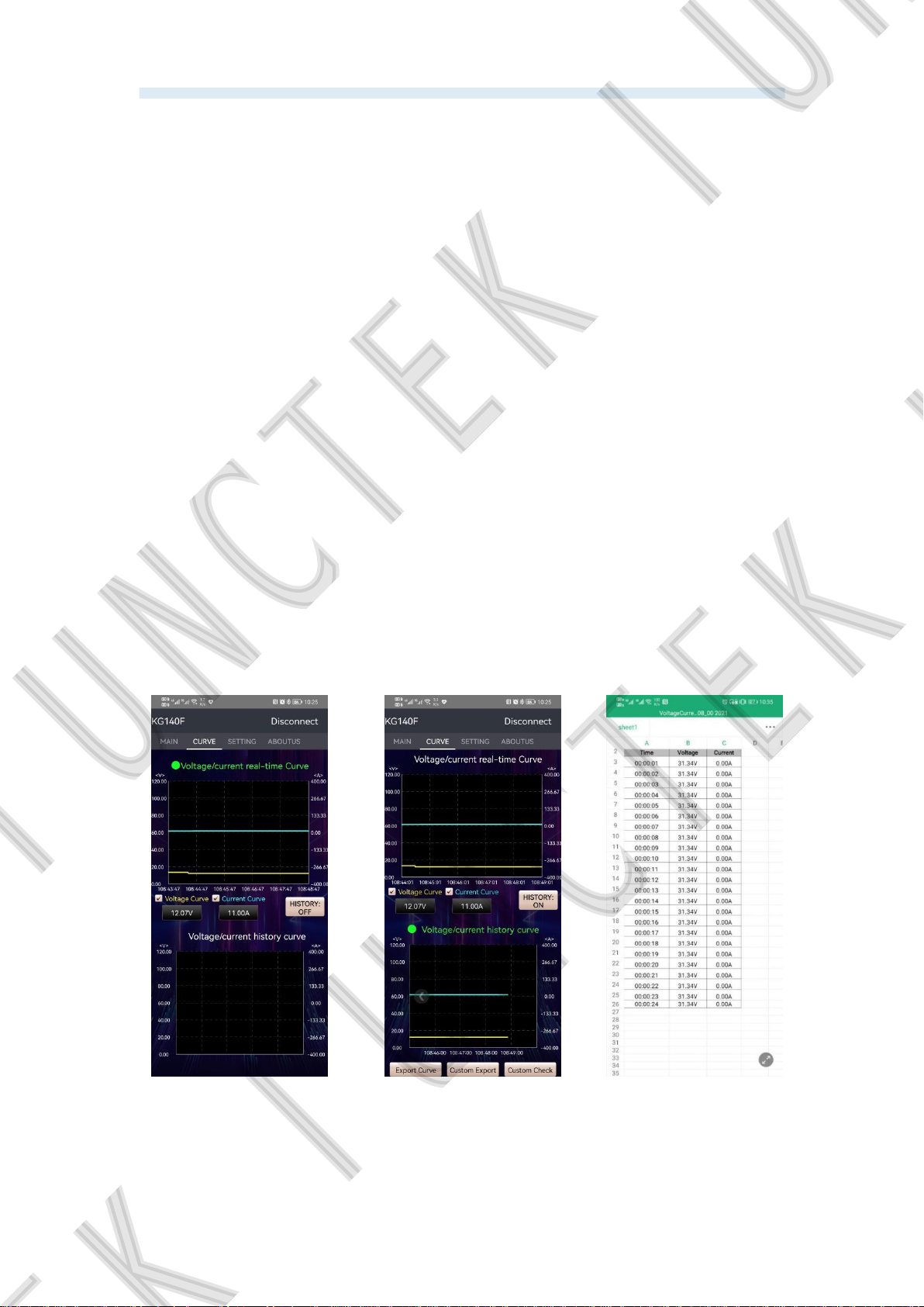
Voltage and current real-time curve: When the green circle icon appears
before the text of the voltage and current real-time curve, and the text turns
green, it means that the voltage and current real-time curve is selected, click
the value displayed by the voltage and current, and the voltage or current
real-time curve can be displayed separately. And the opening and closing of
the voltage and current real-time curve is associated with the output state and
the data recording switch of the main interface. Only when the output state and
the data recording switch are turned on (ON), the voltage and current real-time
curve recording will be turned on. The real-time curve of voltage and current is
shown in Figure 3-5-23 below.
Voltage and current history curve: Click the "History: OFF" button to turn
on the voltage and current history curve. At this time, a green circular icon
appears before the text of the voltage and current history curve, and the text
turns green, and the button changes to "History: ON"; click The value
displayed by voltage and current can display the voltage or current history
curve separately; in the voltage and current history curve graph, you can slide
left and right to view the voltage and current curve in the historical time, as
shown in Figure 3-5-24 Voltage and current history curve .
Export curve: When viewing the voltage and current history curve, the
export curve button will appear. After clicking it, an EXECL file will be
generated, and the voltage and current values of the history curve can be
viewed at a specific time, as shown in Figure 3-5-25.
33
Page 38
Hangzhou Junce Instruments Co., Ltd.
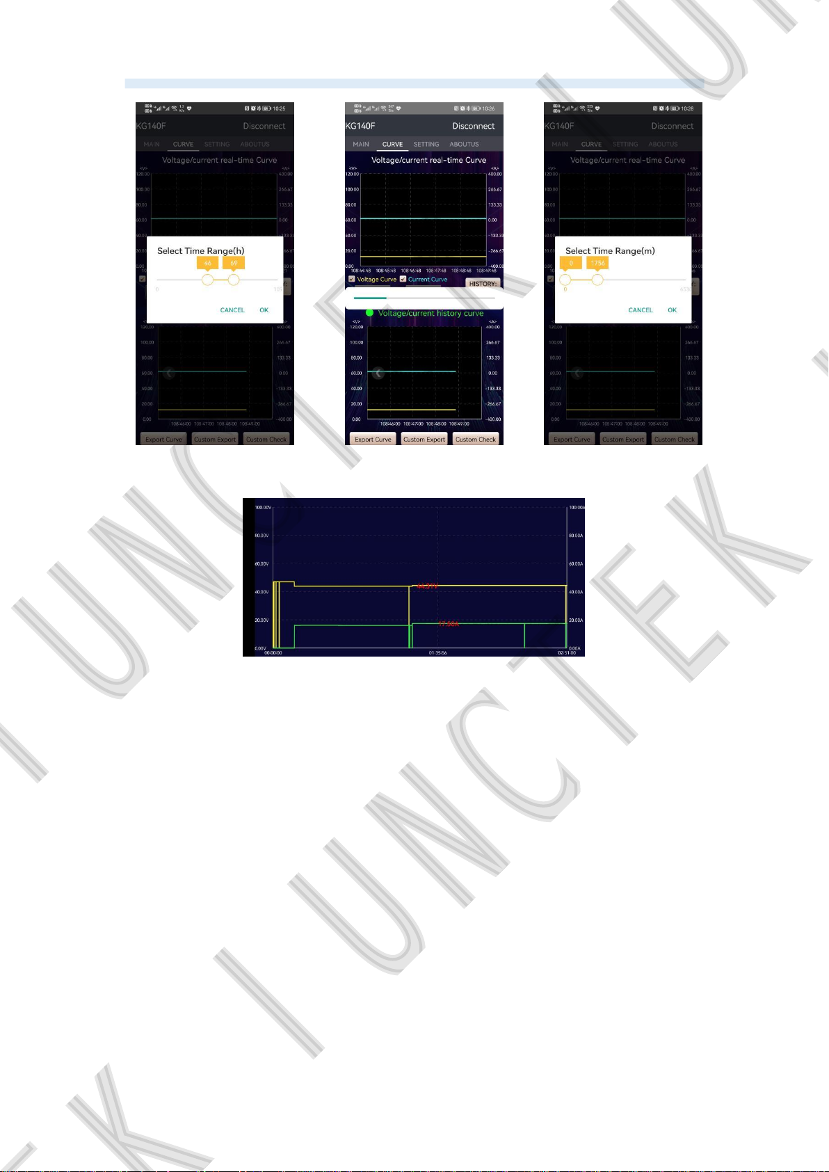
Custom export curve: When viewing the voltage and current history curve,
the export curve button will appear. After clicking, select the time range of the
export curve. After the export is confirmed, the export progress will be
displayed on the screen. The completion of the progress bar indicates the
success of the export curve data. Note: Do not close the KG application during
the process of exporting the curve. The maximum time range for exporting is
12 hours, and the longer the exporting time is, the longer the exporting time will
be. When exporting curve data, please wait patiently. The following figure
3-5-26 is the export curve, As shown in the figure below,3-5-27 is the export
curve progress bar.
Custom viewing curve: When viewing the voltage and current history
curve, the View Curve button will appear. After clicking, select the time range
for viewing the curve. After confirming the viewing, the export progress will be
displayed on the screen. After the progress bar is finished, it will enter the
horizontal screen interface. You can view the voltage and current trends during
this period of time, click on the curve, you can easily view the voltage and
current values at that point in time. Note: Do not close the KG application while
viewing the curve. The maximum time range you can select to view is 12 hours,
and the longer you select to view, the longer you can view the curve. Please be
patient when entering to view the curve. As shown in the figure below, 2-5-28 is
the export curve, and the figure 2-5-29 is the progress bar of the export curve.
Figure 3-5-23
Voltage/current
real-time curve
Figure 3-5-24
Voltage/current history
curve
34
Figure 3-5-25
Export curves
Page 39
Hangzhou Junce Instruments Co., Ltd.
Figure 3-5-26
Export curve
Export curve progress bar
Figure 3-5-27
Figure 3-5-28 Select
Time Range
Figure 3-5-29 view curve
System setting interface operation
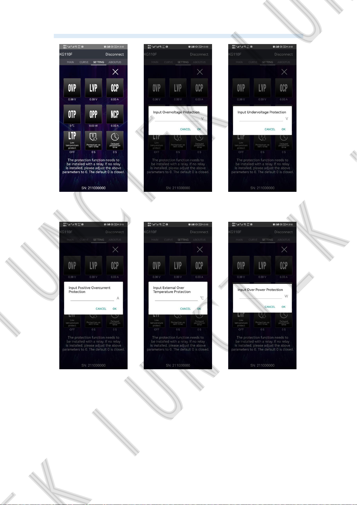
Protection function: Click the protection function button to enter the protection
function interface. The protection function needs to be installed with a relay. If
no relay is installed, please adjust the protection setting parameters to 0. The
default 0 is to close the protection function. As shown in Figure 3-5-30 below.
Over-voltage protection: Click the OVP button to jump out the “Input
over-voltage protection” pop-up window, enter the corresponding value and
click OK to complete the modification, as shown in Figure 3-5-31 below.
Under-voltage protection: Click the LVP button to jump out the “Input
under-voltage protection” pop-up window, enter the corresponding value and
click OK to complete the modification, as shown in Figure 3-5-32 below.
Input Positive Over-current Protection: Click the OCP discharge over current
35
Page 40

Hangzhou Junce Instruments Co., Ltd.
protection button, and the“Input positive over current protection”pop-up box
will pop up, enter the corresponding value and click OK to complete the
modification, as shown in Figure 3-5-33 below.
Over-temperature protection: Click the OTP over temperature protection
button, the“Input external over temperature protection”pop-up box will pop
up, enter the corresponding value and click OK to complete the modification,
as shown in Figure 3-5-34 below.
Over power protection: Click the OPP over-power protection button, the“Input
over power protection”pop-up box will pop up, enter the corresponding value
and click OK to complete the modification, as shown in Figure 3-5-35 below.
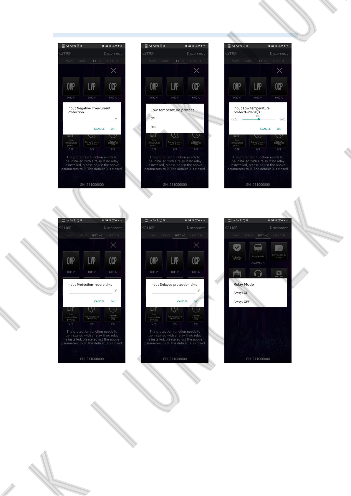
Input Negative Over-current Protection: Click the NCP charging over-current
protection button, the“Input negative over current protection”pop-up box will
pop up, enter the corresponding value, click OK to complete the modification,
as shown in Figure 3-5-36below.
Low temperature protection: Click the low temperature protection to pop up the
"low temperature protection pop-up" pop-up box, you can choose to turn on or
off the low temperature protection, click to open to pop up the pop-up box
"input low temperature protection (-20-20)℃", enter the corresponding value
and click OK to complete the modification. The low temperature protection
function is not activated by default. When we set the low temperature
protection value to 0°C, if the value is less than 0°C, the protection will be
activated. The upper right corner of the APP main interface will display LTP,
which is in the protection state. As shown in Figure 3-5-37 and Figure 3-5-38
below.
Protection recovery time: Click the protection recovery time button to pop out
the "Enter protection recovery time" pop-up box, enter the corresponding value
and click OK to complete the modification, as shown in Figure 3-5-39 below.
Delay time: Click the delay time button to pop out the "Input delay time" pop-up
box, enter the corresponding value and click OK to complete the modification,
as shown in Figure 3-5-40 below.
Relay type: Click the relay type button to pop out the "Relay type normally
open and normally closed option" pop-up box, select the relay type relative to
the actual, as shown in Figure 3-5-41 below.
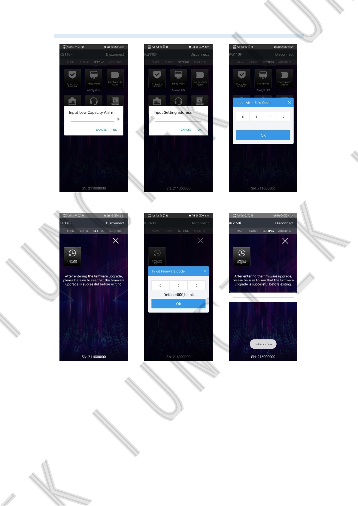
Low-capacity reminder: Click the low-capacity reminder to pop up the pop-up
box "Enter low-capacity reminder", enter the corresponding capacity
percentage and click OK to complete the modification. When the KG-F mobile
36
Page 41

Hangzhou Junce Instruments Co., Ltd.
APP is connected to the instrument's Bluetooth, of course, the battery capacity
percentage is lower than the set value. , a low capacity reminder will be
displayed in the status bar of the mobile phone, as shown in Figure 3-5-42
below.
Set Address: Click the Set Address button to pop out the "Enter Set Address"
pop-up box, enter the corresponding value and click Confirm to complete the
modification of the communication address, as shown in Figure 3-5-43 below.
After-sales service: Click the after-sales service button to pop out the "Please
enter the after-sales code" pop-up box, enter "8 6 1 0" and click OK to enter
the after-sales service interface, as shown in Figure 3-5-44 and Figure 3-5-45
below.
Firmware upgrade: In the after-sales service interface, click Firmware Upgrade
to bring up the "Please enter the firmware code" pop-up box, enter the
firmware code "0 0 0" and click OK, the instrument starts the firmware upgrade,
and the indicator light of the measurement module flashes rapidly at this
moment, indicating that the firmware is in progress During the upgrade, please
wait patiently during the upgrade process, and do not perform other operations.
After the upgrade is completed, the message "Upgrade Successful" will be
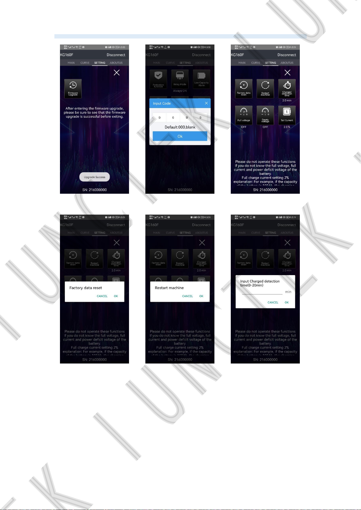
displayed. The firmware upgrade sequence is as follows: Figure 3-5-46
Firmware upgrade 01, Figure 3-5-47 Firmware upgrade 02, Figure 3-5-48
Firmware upgrade 03. Note: After entering the firmware upgrade, please be
sure to see that the firmware upgrade is successful before exiting.
Firmware update log: http://68.168.132.244/KG-F_DFU_log_EN.pdf
Extended service: Click the extended service button to pop out the "Please
enter the password" pop-up box, enter "0 0 0 0" and click OK to enter the
extended service interface, as shown in Figure 3-5-49 and Figure 3-5-50 below.
Note: Please do not operate these functions if you do not know the full voltage,
full current and power deficit voltage of the battery.
Restore factory settings: Click the Restore Factory Settings button to pop out
the "Restore Factory Settings" pop-up box, select OK to restore the instrument
to factory settings, as shown in Figure 3-5-51 below.
Restart the machine: Click the restart machine button to pop out the "Restart
machine" pop-up box, select OK to restart the instrument, as shown in Figure
3-5-52 below.
Detection time: Click the detection time button to pop out the "Input detection
time (0-20min)" pop-up box, enter the corresponding value and click OK to
37
Page 42

Hangzhou Junce Instruments Co., Ltd.
complete the modification, as shown in Figure 3-5-53 below.
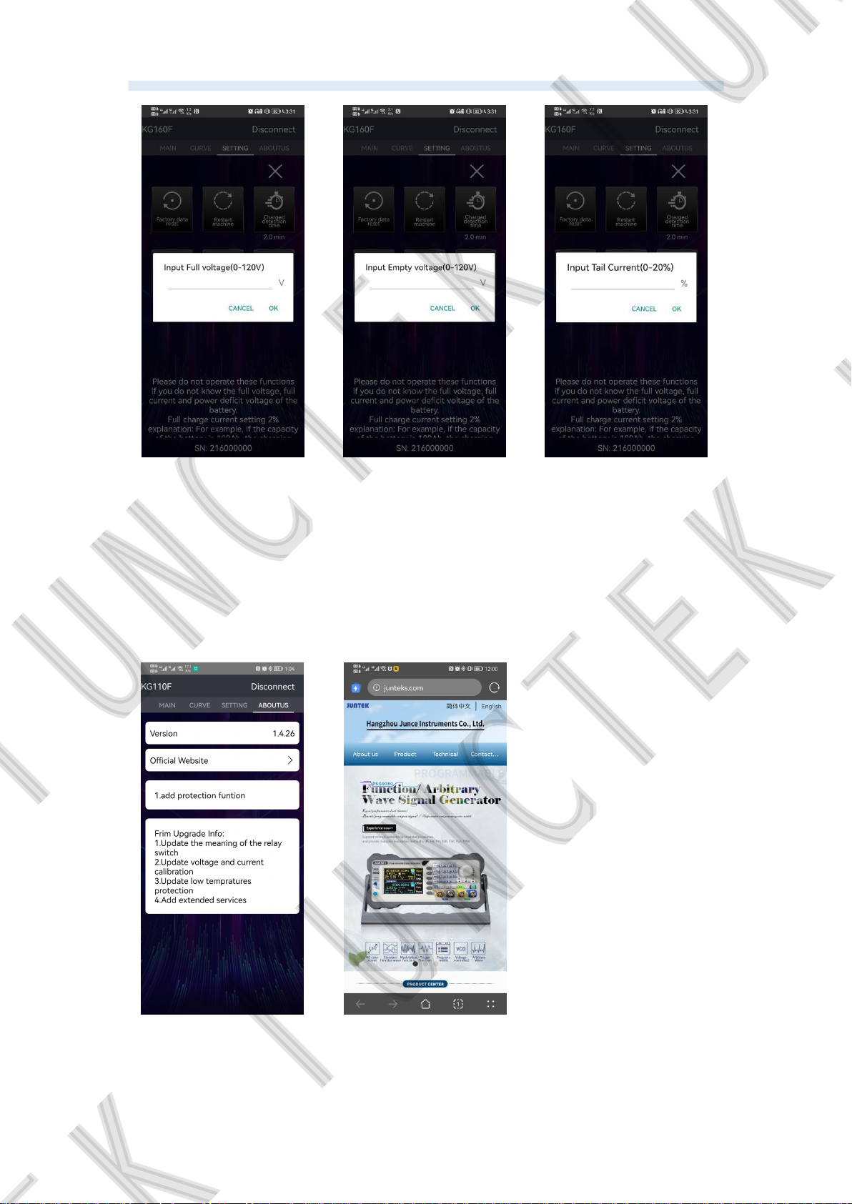
Full voltage: Click the full voltage button to pop out the "Input full voltage
(0-120V)" pop-up box, enter the corresponding value and click OK to complete
the modification, as shown in Figure 3-5-54 below.
Power loss voltage: Click the power loss voltage button to pop out the "Input
power loss voltage (0-120V)" pop-up box, enter the corresponding value and
click OK to complete the modification, as shown in Figure 3-5-55 below.
Full current: Click the full current button to pop out the "Input full current
(0-20%)" pop-up box, enter the corresponding value and click OK to complete
the modification, as shown in Figure 3-5-56 below.
Description of full power voltage, power deficit voltage, full power current, and
detection time:
For example, for a 12V400Ah lead-acid battery, set the full voltage to 14.4V
and the full current to 2%, which means that the full current is 400*0.02=8A,
and the detection time is set to 2 minutes, which means that during the
charging process, when the voltage is higher than 14.4 V. After the charging
current is lower than 8A and the duration exceeds 2 minutes, the percentage of
remaining capacity will be automatically adjusted to 100%;
Set the power-loss voltage to 10.5V and the detection time to 2 minutes, which
means that when the voltage is lower than 10.5V during the discharge process
and the duration exceeds 2 minutes, the percentage of remaining capacity will
be automatically adjusted to 0% (if you feel that the power-loss voltage is this If
the function is not very practical, you can set the full voltage, full current, and
detection time without setting the voltage deficit);
38
Page 43
Hangzhou Junce Instruments Co., Ltd.
Figure 3-5-30 Protection
function
Figure 3-5-31
Overvoltage protection
Figure 3-5-32
Undervoltage
protection
Figure 3-5-33 Discharge
overcurrent protection
Figure 3-5-34 Over
temperature protection
39
Figure 3-5-35
Overpower protection
Page 44
Hangzhou Junce Instruments Co., Ltd.
Figure 3-5-36 Charging
overcurrent protection
Figure 3-5-37 Low
temperature protection
01
Figure 3-5-38 Low
temperature protection
02
Figure 3-5-39 Protection
recovery time
Figure 3-5-40 Delay
protection time
40
Figure 2-5-41 Relay
type
Page 45
Hangzhou Junce Instruments Co., Ltd.
Figure 3-5-42 Low
volume reminder
Figure 3-5-45 Low
temperature protection
02
Figure 3-5-43 Setting
address
Figure 3-5-46 Firmware
upgrade 01
Figure 3-5-44 After-sale
service 01
Figure 3-5-47 Firmware
upgrade 02
41
Page 46
Hangzhou Junce Instruments Co., Ltd.
Figure 3-5-48 Firmware
upgrade 03
Figure 3-5-51 Restore
factory settings
Figure 3-5-49 Extended
function 01
Figure 3-5-52 Restart
the machine
Figure 3-5-50 Extended
function 02
Figure 3-5-53 Detection
time
42
Page 47
Hangzhou Junce Instruments Co., Ltd.
Figure 3-5-54 Full
voltage
Figure 3-5-55 Deficit
voltage
Figure 3-5-56 Full
current
About...interface operation
Version: you can view the software version information, as shown in figure
3-5-57.
Official website: after clicking the official website, you can jump to our
company's official website, as shown in figure 3-5-58 below.
Figure 3-5-57
version
Figure 3-5-58
official website
43
Page 48
Hangzhou Junce Instruments Co., Ltd.
2. App Instructions (For IOS)
Apple Mobile App installation and operation demonstration video:
https://youtu.be/IFtG6Li8yfk
(1) APP download
Search for “KG-F series” in the Apple Store to download.
(2) App software installation
The software only supports IOS 9.0 or above. Bluetooth will be accessed
when the software is first linked. Please agree to visit.
Bluetooth module can not be plugged in and out of power state, which will
cause damage. This manual corresponds to software version 1.2.1. Different
versions may be slightly different. It is recommended to upgrade to the latest
software to obtain better use experience.
(3) Software update
You can get the latest version from the Apple Store. The current manual
corresponds to the IOS software version is 1.2.1.
(4) APP interface display
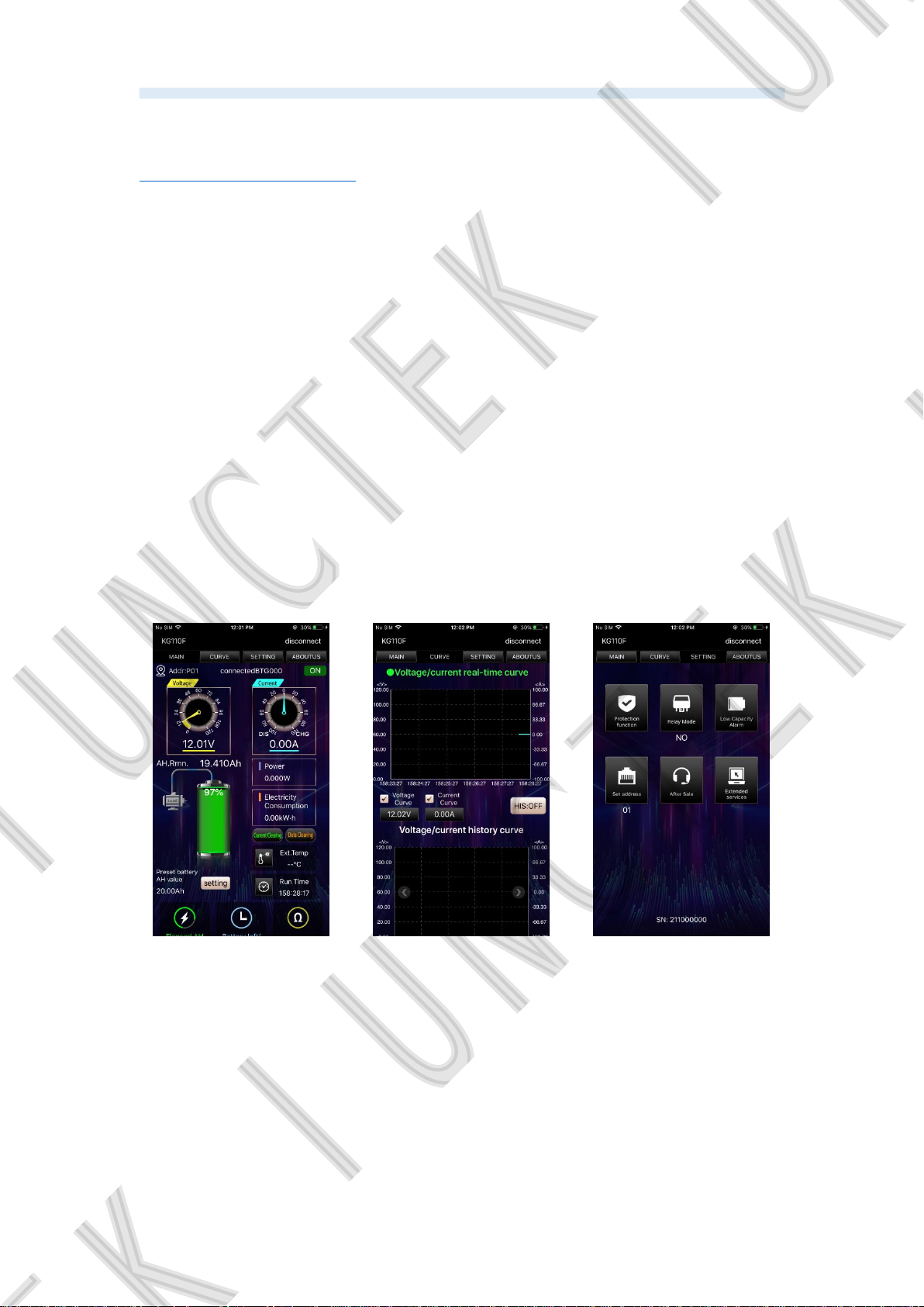
Figure 3-5-59
Main interface
Figure 3-5-60
Curve diagram
Figure 3-5-61
System settings
44
Page 49
Hangzhou Junce Instruments Co., Ltd.
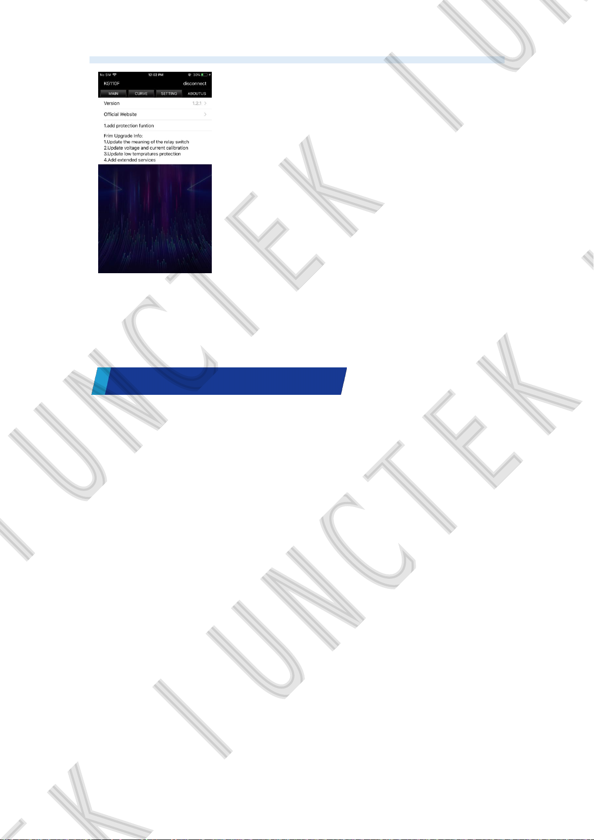
Figure 3-5-62 About us
(5) App operating instructions
The operation of IOS is the same as the Android.
Chapter
The following lists the possible problems and troubleshooting methods of the
KG-F series during use. When you encounter these problems, please follow
the corresponding steps to deal with it. If you cannot deal with it, please
contact JUNCTEK Hangzhou Junce Instruments Co., Ltd., and please provide
your equipment information.
If the screen is still black after power on, and there is nothing display:
Check whether the power wiring and the wiring between the display board
and the main board are well connected.
After finishing the above checks, restart the meter.
If the product still cannot be used normally, please contact JUNCTEK.
If the screen display is too dark to see clearly:
Check whether the brightness setting value of the LCD screen is too small.
Press the 【SET】 button to enter the system setting interface, then press
【▲】【▼】buttons to make the cursor on the working screen brightness.
Press the 【OK】button and then use the 【▲】【▼】buttons to adjust the
brightness of the LCD screen to a suitable state.
Troubleshooting
Ⅳ
ChapterⅤ For More product information
45
Page 50
Hangzhou Junce Instruments Co., Ltd.
For more information about this product, please refer to the relevant
manual (you can log in to the JUNCTEK official website (www.junteks.com) to
download).
"KG-F series operation demonstration video" provides the operation video
of this product.
"KG-F series PC software and communication protocol" provides the
communication protocol.
"KG-F Series User Manual" provides the function introduction and
operation of this product, possible problems and treatment methods during
use.
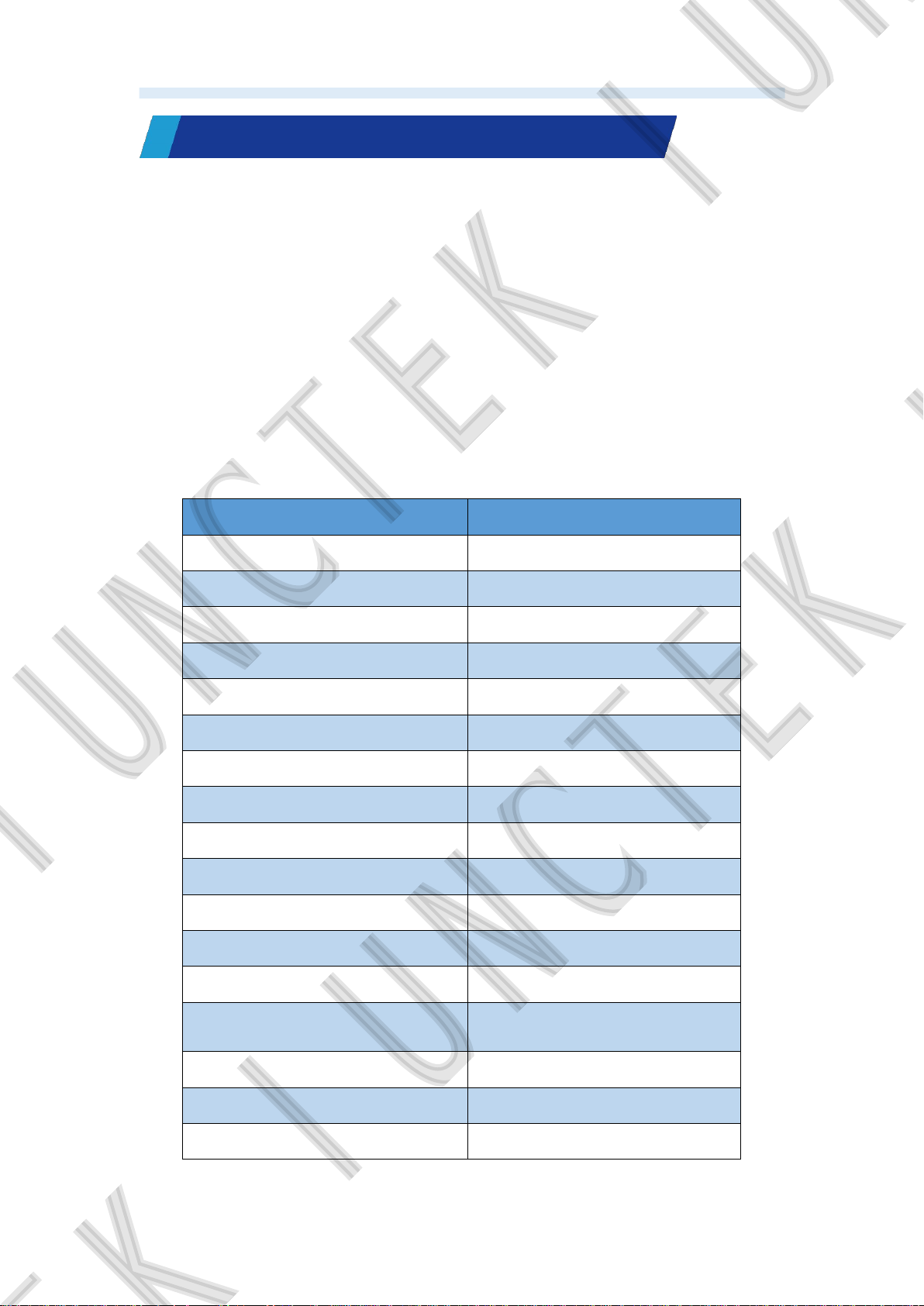
Appendix 1: English and abbreviations of the interface
English English abbreviation
Output State! Output State!
Data Record Data Record
Series number SN
Display module version Disp Mod Ver.
Measuring module version Meas Mod Ver.
Remaining AH. value AH.Rmn.
Elapsed AH value AH.Elp.
Battery left BatLeft
Battery internal resistance IntRes
Language selection Language
Set current to zero Setcurrentto0
Clear accumulated data Clear data
Preset battery AH. value AH.Preset:
Percentage of remaining
capacity
AH.Remaining:
Screen brightness Brightness
Under-voltage protection LVP
Over-voltage protection OVP
46
Page 51
Hangzhou Junce Instruments Co., Ltd.
Forward over-current protection OCP
Negative over-current protection NCP
Over power protection OPP
Over temperature protection OTP
Protection-revert-time Revert Time
Enter standby time Standby Time
Voltage calibration Voltage Cal.
Current calibration Current Cal.
Temperature calibration Temp. Cal
Set address Address
Set delay time Delay Time
Current ratio Current Ratio
Monitor function Monitor
Relay Mode Relay Mode
The scale of the voltage curve Voltage Scale
The scale of the current curve Current Scale
Restore to factory settings Restore all
About About
Enter the curve interface Curve Interface
OK OK
Cancel Cancel
Voltage real-time curve Voltage Curve
Current real-time curve Current Curve
Voltage/current real-time curve V/A Real-Time Curve
Voltage history curve V History Curve
Current history curve A History Curve
Voltage/current history curve V/A History Curve
Voltage/current Curve Voltage/current Curve
Voltage curve V-Curve
Current curve A-Curve
47
Page 52
Hangzhou Junce Instruments Co., Ltd.
Normally open NO
Normally close NC
Completed Completed
Failed Failed
NO NO
OFF OFF
48
 Loading...