

Page 1
6 720 604 574 (02.98)
OSW
TR 100
7 744 901 112
English
Correct function of this appliance can only be guaranteed if
these instructions are observed. Please hand this document
over to the customer.
Po polsku
W∆a∂ciwe funkcjonowanie zapewnione jest tylko pod
warunkiem przestrzegania niniejszej instrukcji. Prosimy o
zaƌczenie instrukcji Klientowi.
âesky
Bezvadné funkce je dosaÏeno pouze tehdy, budete-li dbát
tohoto návodu. Prosíme pfiedejte tento návod zákazníkovi.
Slovensky
Bezchybná funkcia je zaruãená len pri dodrÏaní tohto
návodu. Prosíme Vás, poskytnite zákazníkom túto
dokumentáciu.
Magyar
A készülék kifogástalan mæködését csak akkor tudjuk
szavatolni, ha a felhasználó az ebben a leírásban található
utasításokat betartja. Kérjük, adja át a Vevœnek ezt a
brosúrát.
Slovensko
Brezhibno delovanje bo zagotovljeno le ob upo‰tevanju teh
navodil. Prosimo, da kupec prejme ta navodila.
Hrvatski
Besprijekorno djelovanje jamãi se samo ako se strogo
po‰tuju ove opute. Mollmo da se ove upute uruãe kupcima.
Latviski
Nevainojama funkcionï‰ana ir garanteta tikai tad, ja ievero
‰o instrukciju. Ldzam to izsniegt pircïjam.
4476-00.1/O
JUNKERS
CERACONTROL
15
5
10
20°C
25
30
Page 2
2
TR 100
Page 3
3
TR 100
1
10
20
25
5
30
15°C
4476-01.1/O
2515
3010
5
20°C
eopfghi
lkmn
4476-02.1/O
i
JUNKERS
CERACONTROL
10
15
5
20°C
25
30
2
4476-03.1/O
JUNKERS
15
10
20°C
25
30
192
46
176
98
CERACONTROL
5
3
4192-03.1/G
0,3m
min.
0,3m
0,6m
1,2 - 1,5m
4
4476-05.1/O
JUNKERS
15
10
20°C
25
30
CERACONTROL
5
b1
b1
b1
b
a
b1
5
Page 4

4
TR 100
English
1 Safety Instructions ........................................5
2 Application ....................................................5
3 Technical Data .............................................5
4 Mounting ......................................................6
5 Mains Connection ........................................6
6 Operation .....................................................7
7 Regulator Malfunction Message .................10
8 General Information ...................................11
9 Elimination of malfunctions ........................12
Po polsku
1 Wskazówki bezpieczeµstwa .......................13
2 Zastosowanie .............................................13
3 Dane technicznen ......................................13
4 Monta† regulatora ......................................13
5 Podƌczenie elektryczne ............................14
6 Obs∆uga ......................................................15
7 Komunikaty regulatora ...............................18
8 Wskazówki ogólne .....................................19
9 Zak∆ócenia i poszukiwanie przyczyn ..........20
âesky
1 Bezpeãnostní pfiedpisy .............................21
2 PouÏití .......................................................21
3 Technické údaje .......................................21
4 MontáÏ ......................................................21
5 Elektrické pfiipojení ...................................22
6 Obsluha ....................................................22
7 Hlá‰ení regulátoru ....................................25
8 V‰eobecné pokyny ...................................26
9 Hledání závad ...........................................27
Slovensky
1 Bezpeãnostné pokyny ..............................28
2 PouÏitie .....................................................28
3 Technické údaje .......................................28
4 MontáÏ ......................................................28
5 Elektrické zapojenie ..................................29
6 Obsluha ....................................................29
7 Hlásenia regulátora ..................................32
8 V‰eobecné pokyny ...................................33
9 Vyhºadávanie ch˘b ...................................34
Magyar
1 Biztonsági tájékoztató ................................ 35
2 A készülék alkalmazási területei ................ 35
3 Mæszaki adatok .......................................... 35
4 Felszerelés ................................................ 35
5 Elektromos csatlakozás ............................. 36
6 Kezelés ...................................................... 37
7 A szabályozó kijelzése ............................... 40
8 Általános tájékoztató .................................. 41
9 Hibakeresés ............................................... 42
Slovensko
1 Varnostni napotki .....................................43
2 Uporaba ...................................................43
3 Tehniãni podatki ....................................... 43
4 Namestitev ...............................................43
5 Elektriãni priklop ....................................... 44
6 Upravljanje ...............................................44
7 Regulator - poroãilo ..................................47
8 Splo‰ni napotki .........................................48
9 Iskanje napak ........................................... 49
Hrvatski
1 Upute za siguran rad ................................50
2 Primjena ...................................................50
3 Tehniãki podaci ........................................ 50
4 MontaÏa ...................................................50
5 Elektriãni prikljuãak ................................... 51
6 PosluÏivanje .............................................51
7 Dojava regulatora .....................................54
8 Opçi napuci .............................................. 55
9 TraÏenje neispravnosti ............................. 56
Latviski
1 Dro‰¥bas norÇd¥jumi ................................. 57
2 Lieto‰ana ..................................................57
3 Tehniskie dati ........................................... 57
4 MontÇÏa ...................................................57
5 Elektriskais pieslïgums ............................58
6 Apkalpo‰ana ............................................59
7 RegulÇtora zi¿ojums ................................62
8 VispÇr¥gi norÇd¥jumi .................................63
9 K∫mju meklï‰ana ....................................64
Page 5
English
TR 100
5
1 Safety Instructions
The regulator is to be used only in connection with the listed Junkers gas heating
units. The respective circuit diagram must
be observed.
The regulator must under no circumstances be connected to the 230 V
mains.
Before installing the regulator, the voltage supply (230 V, 50 Hz) to the heating
unit must be interrupted.
The regulator is not suited for installation in damp rooms.
2 Application
TR 100 is a room temperature regulator with a
digital time switch (daily programme for one
heating and one reduction starting time; equal
for all days of the week) for controlling the
Junkers gas heating units with continuous
control listed below.
TR 100 is in accordance with the regulations
and is recommended for floor-areas up to approx. 80 m
2
.
The room temperature regulator TR 100 is not
suited for buildings with underfloor heating
systems. In those buildings we recommend
the use of a regulator controlled by atmospheric conditions.
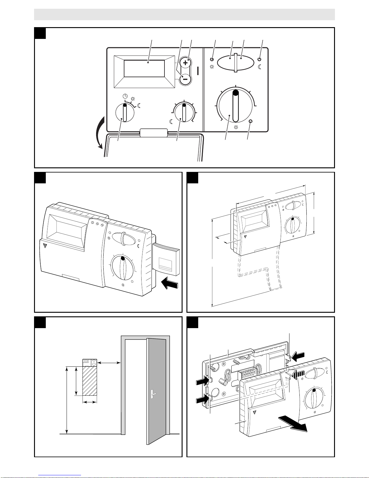
2.1 Scope of delivery
TR 100 includes the room temperature regulator with inserted brief operating instructions
(illustration ).
2.2 Accessory
An external room temperature sensor RF 1 in
addition to TR 100 is available as accessory.
For example, the use of this temperature sensor is of advantage when the mounting location of the regulator is not suited for measurement of temperature (see chapter 4).
Furthermore, a remote control switch (e.g. a
telephone commander) can be connected by
customers (see chapter 6.7).
The remote control switch must be equipped
with a potential-free contact which is suited for
5 V DC.
3 Technical Data
Heating unit Mains
connection
Malfunction
remote indicator active
ZE/ZWE .. K... Illustr. no
ZE/ZWE .. - 1 K... Illustr. no
ZE/ZWE .. - 2 K... Illustr. no
ZE/ZWE .. - 1 A... Illustr. no
ZE/ZWE .. - 2 A... Illustr. no
ZR/ZWR/ZSR...-3 Illustr. no
ZR/ZWR/ZSR...-4 Illustr. no
Heating equipment
with
Bosch Heatronic Illustr. yes
9
9
9
10
10
10
10
11
Dimensions
see illustration
Rated voltage 24 V DC
Rated current 0.02 A
Regulating range 5 to 30 °C
Regulator output constant,
2.5 to 21 V DC
Permissible ambient
temperature 0 to +40 °C
Operating reserve approx. 2 hrs.
Protection class IP 20
2
3
Page 6
English
6
TR 100
4 Mounting
Before mounting the regulator, the voltage supply (230 V, 50 Hz) to the heating
unit must be interrupted.
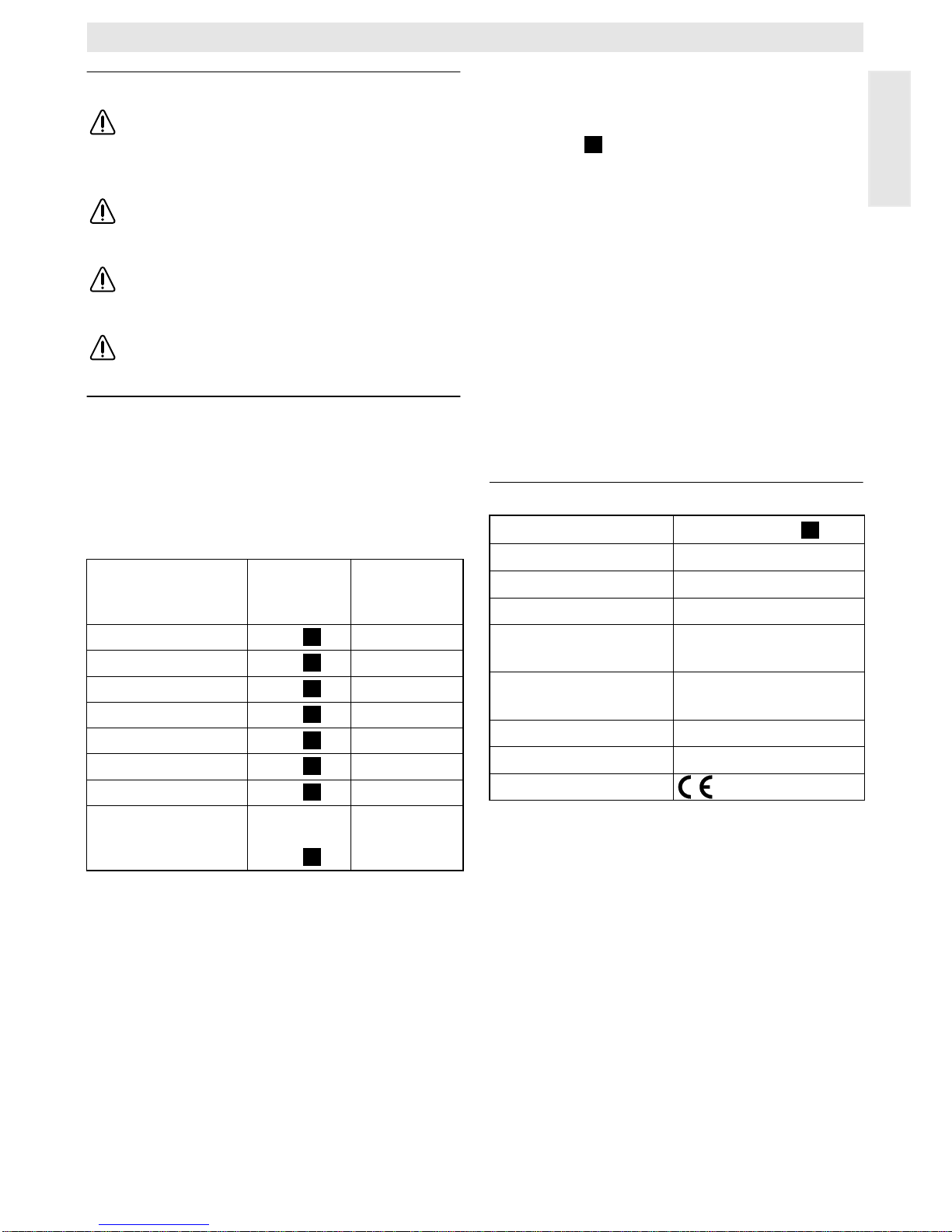
4.1 Selecting the mounting location
It is important for the regulation quality of
TR 100 to select a suitable mounting location.
The installation room must be suitable for the
temperature regulation of the complete heating
system. The radiators installed in those rooms
must not be equipped with thermostatic valves.
Instead, hand valves with pre-adjustment
should be installed so that the heating output of
the radiators in the installation room of TR 100
can be set to the lowest possible value.
For the mounting location, select an interior
wall if possible and take care that neither
draughts nor heat radiation (not from behind
the wall, either, e.g. through ducts or hollow
walls, etc.) can have effects on the regulator.
Adequate space must be provided above and
below the regulator so that the room air can
circulate unimpeded through the ventilation
openings (hatched area in illustration
).
If the above mentioned conditions cannot all
be met it is recommended to use the external
room temperature sensor RF 1 (accessory)
and to mount this on a more adequate location.
When connecting the room temperature sensor RF 1 the built-in sensor in the regulator is
automatically deactivated.
4.2 Mounting the regulator
• Loosen the top (a) from the base (b) depress the fasteners on the sides (b1) oft the
base and pull off the top (a) (illustration ).
• The base (b) can be mounted either
– with two screws (c) to a standard flush
connection box (d) dia. 55 mm
or
– with 4 dowels (6 mm) and tallow-drop
screws (dia. 3.5 mm) directly to the wall
(illustration );
Take care that the regulator is mounted in
the right position (the clip must be legible)!
• Connect with the mains accordingly (see
chapter 5).
• Fit the regulator top (a) .
4.3 Mounting the accessories
The accessories external room temperature
sensor RF 1 and remote control switch (if existing) must be mounted according to the regulations and the respective mounting instructions.
5 Mains Connection
The following conductor cross sections from
TR 100 to the heating unit must be used:
Considering the regulations, at least cables of
the construction type NYM must be used for
mains connection.
All 24 V cables (test current) must be laid separated from cables leading 230 V or 400 V so
that no inductive influencing can take place
(minimum distance100 mm).
In case that inductive external influences e.g.
from power current cables, contact wires,
transformer towers, radio and television sets,
amateur radio sets , microwave equipment, or
similar are to be expected the cables leading
test signals must be shielded.
The corresponding electrical connection plan
(illustration
to ) is to be followed :
5.1 Accessory mains connection
Connect the external room temperature sensor RF 1 (if existing) as shown in
illustration
.
If required, the cables of RF 1 can be extended with a cable with twisted twin conductors.
This will make sure that the measured values
of the sensor will not be influenced.
Connect the remote control switch (if existing)
as shown in illustration For minimum requirements see chapter 2.2 accessories.
When the switching contact of the remote control switch is deactivated the heating system
will switch to economical operating mode, “F”
is displayed. When the switching contact is
activated the mode of operation set at the regulator is also activated (illustration ).
4
5
6
Length up to 20 m 0.75 mm
2
up to 1.5 mm
2
Length up to 30 m 1.0 mm
2
up to 1.5 mm
2
Length over 30 m 1.5 mm
2
9 11
7
8
8
Page 7
English
TR 100
7
6 Operation
TR 100 has some operating elements which
are not needed often after installation and initial operation.
Therefore all operating elements which are
not needed often are covered with a lid.
The operating elements visible when the lid is
closed are part of the so-called “1
st
operating
level”. All other operating elements make up
the so-called “2
nd
operating level”.
All special operating conditions as well as
malfunctions are indicated with control lights
(only for heating equipment with Bosch
Heatronic).
When the lid is closed the time is shown.
6.1 The “1
st
operating level” (illustration )
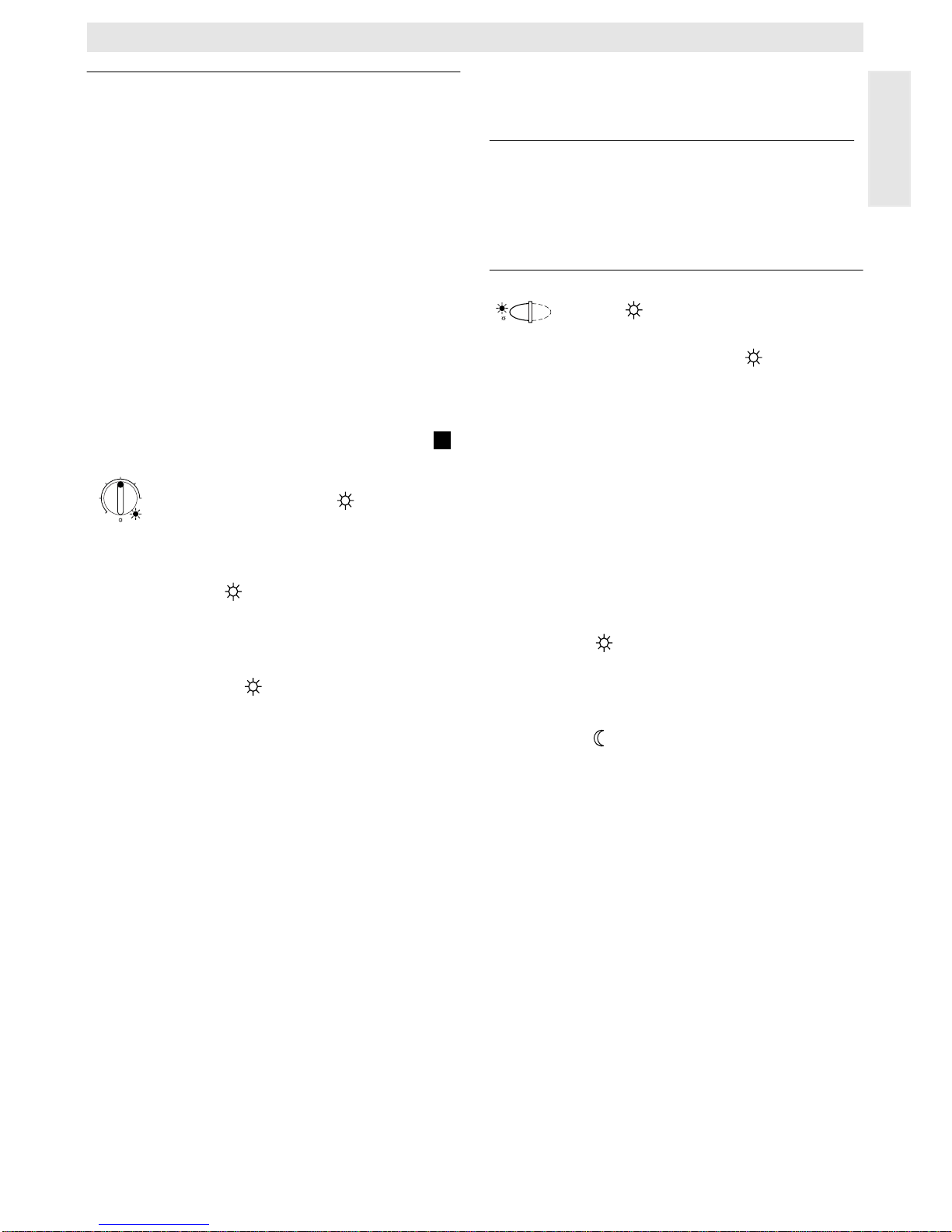
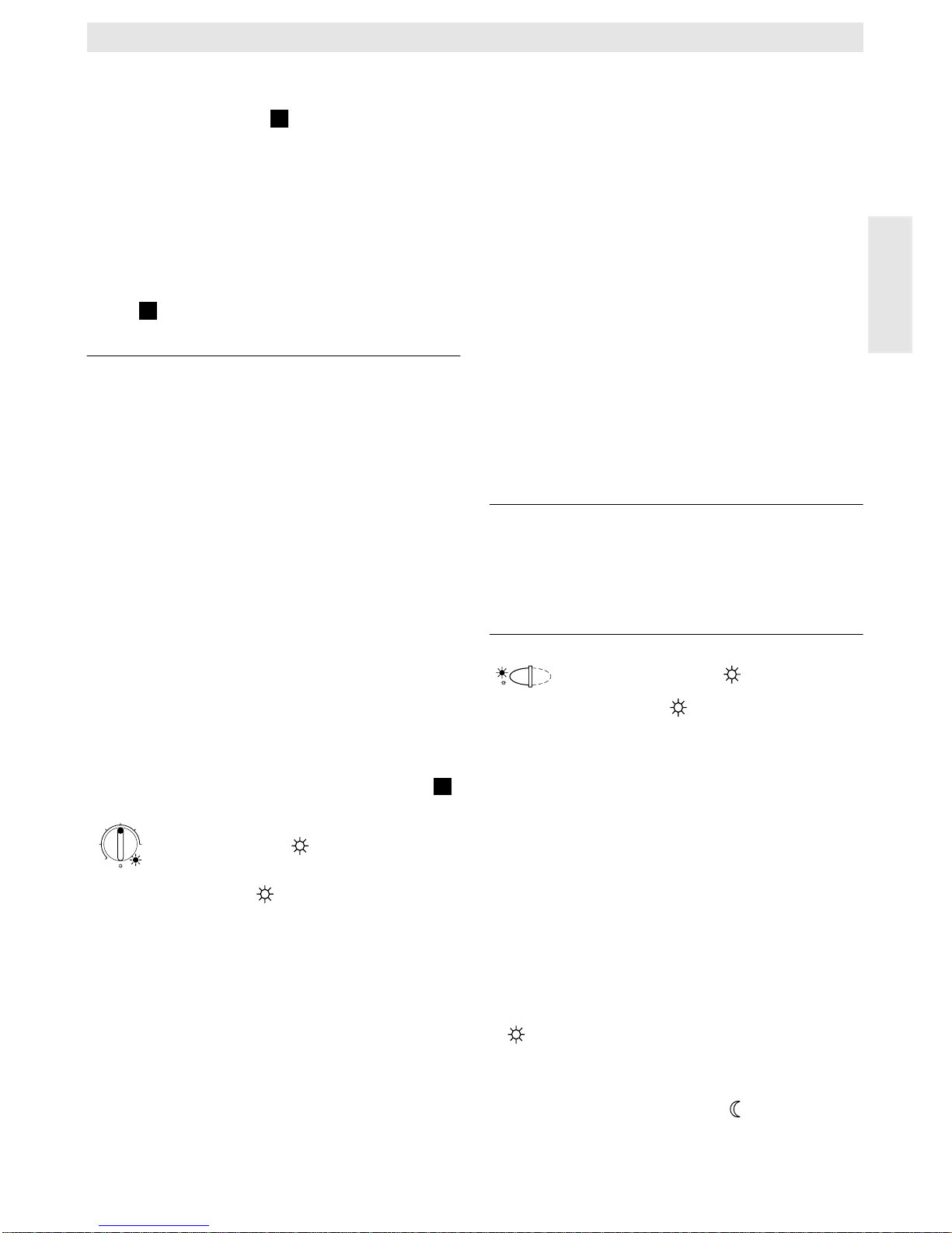
6.1.1 Control knob (k)
The room temperature to which the regulator
will keep in standard heating mode is set with
the control knob (k) .
The regulator will always regulate the temperature to this value when the respective red
control light (l) is on.
If the control knob (k) is set to “5”, the respective red control light (l) is off. The regulator will then set the temperature to approx. 5°C
so that frost protection in this room is guaranteed. The heating system is switched off.
6.1.2 The operating conditions
Automatic operating mode
The basic setting of the regulator is automatic operating mode.
Automatic operating mode means automatic
changeover between standard heating operation and economical operation at the times
pre-set with the time switch (e) .
During standard heating operation (=“day”),
the regulator regulates the room temperature
to the value set with the control knob (k) , the
respective red control light (l) is on.
During economical heating operation
(=“night”), the regulator regulates the room
temperature to the set economic temperature,
the respective red control light (l) is off. (Presetting of economic temperature see
chapter 6.2.1)
Note: Every time the automatic operating
mode is switched off a control light
comes on.
The operating mode can be
switched back to automatic operation at any time.
Button
“Continuous heating mode” (g)
When this button is depressed (g) continuous heating operation is activated.
The regulator continuously regulates the room
temperature to the value set with the control
knob (k) .
The respective red control light (f) is on.
The respective red control light (l) is also on
(unless the control knob (k) is set to “5”).
The economical operating mode set at the
time switch is ignored.
The operating mode “continuous heating ” will
be activated until:
• the button (g) is depressed again; the
regulator will switch back to the automatic
operating mode
or
• the button (h) is depressed again; the regulator will switch back to economical operating mode.
In both cases the respective red control light (f)
turns off and the regulator will regulate the room
temperature to the set value.
Depress this button if you exceptionally
go to bed late (e.g. because of a party). Switch
back to automatic operating mode later.
In case of an illness it might be more comfortable to have a higher room temperature (continuous heating operation). In this case, do not
forget to switch the regulator back to the automatic operating mode.
During a winter holiday or during the summer,
a low room temperature for a longer period
can be selected by depressing the button
"continuous heating" and additionally reducing the temperature with the control knob (k) .
1
25
15
5
3010
20°C
☞
Tip
Page 8
English
8
TR 100
Button
“Economical operating mode” (h)
When the button (h) is depressed the economical operating mode is switched on.
The regulator continuously regulates the
room temperature to the value set with the
control knob "economic temperature" (setting the economic temperature see
chapter 6.2.1).
The respective yellow control light (i) is on.
The respective red control light (l) is off.
The standard heating mode set at the time
switch is ignored.
The economical operating mode will be active
until
• midnight (00.00 hours)
or
• the button (h) is depressed again;
the regulator is set back to automatic oper-
ating mode
or
• the button (g) is depressed;
the regulator is set to continuous operating
mode.
In all cases the respective yellow control
light (i) will turn off and the regulator will regulate the temperature to the set values.
Use this mode if you exceptionally
leave your house (e.g. for shopping) and the
house should not be heated for this time. As
soon as you are back depress the button (h)
again, the regulator is operating in automatic
mode again and will heat according to the set
temperature.
If you leave the house in the evening or if
you would like to go to bed early depress the
button (h) . The regulator terminates the economical heating mode at midnight and will
switch back to the usual automatic operating
mode the next morning.
6.2 The “2
nd
operating range”
The “2
nd
operating range” is accessible after
opening the lid.
6.2.1Control knob
“economic temperature” (m)
With this control knob (m) the temperature
to which the regulator must regulate in the
automatic operating mode when set to
“economic”, as well as in "economical
operation mode" (h) .
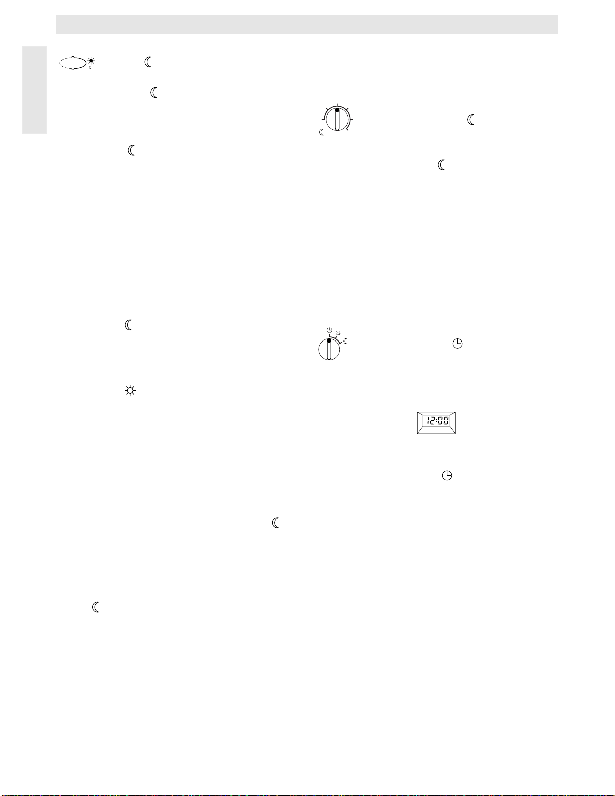
6.2.2 General information on the timer
The time switch makes it possible to automatically switch the heating system on once a day
at a pre-set time, and switch it off automatically once a day at a pre-set time. Those set
times are valid for all days.
Setting the time ( )
The display (e) shows the time (at initial operation or power failure over a longer period the
time pre-set by the factory):
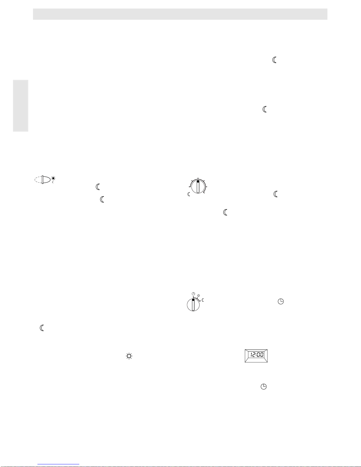
The regulator is automatically set to the programming mode when the lid is opened. Set
the control knob (n) to “ ” .
The time is set by depressing the buttons “-”
(o) or “+” (p) .
Briefly depressing the button alters the time by
1 minute, when the button is depressed for a
longer period the time runs faster forward or
backward. The seconds are set back to “0”. As
soon as the button is released the clock will
operate normally.
If no buttons are depressed the clock also operates normally.
☞
Tip
10
20
25
30
15°C
5
Page 9
English
TR 100
9
The time before 1200 hrs. (12 noon)can
be set faster with the “-” (o) button.
When no more alterations are necessary
close the lid.
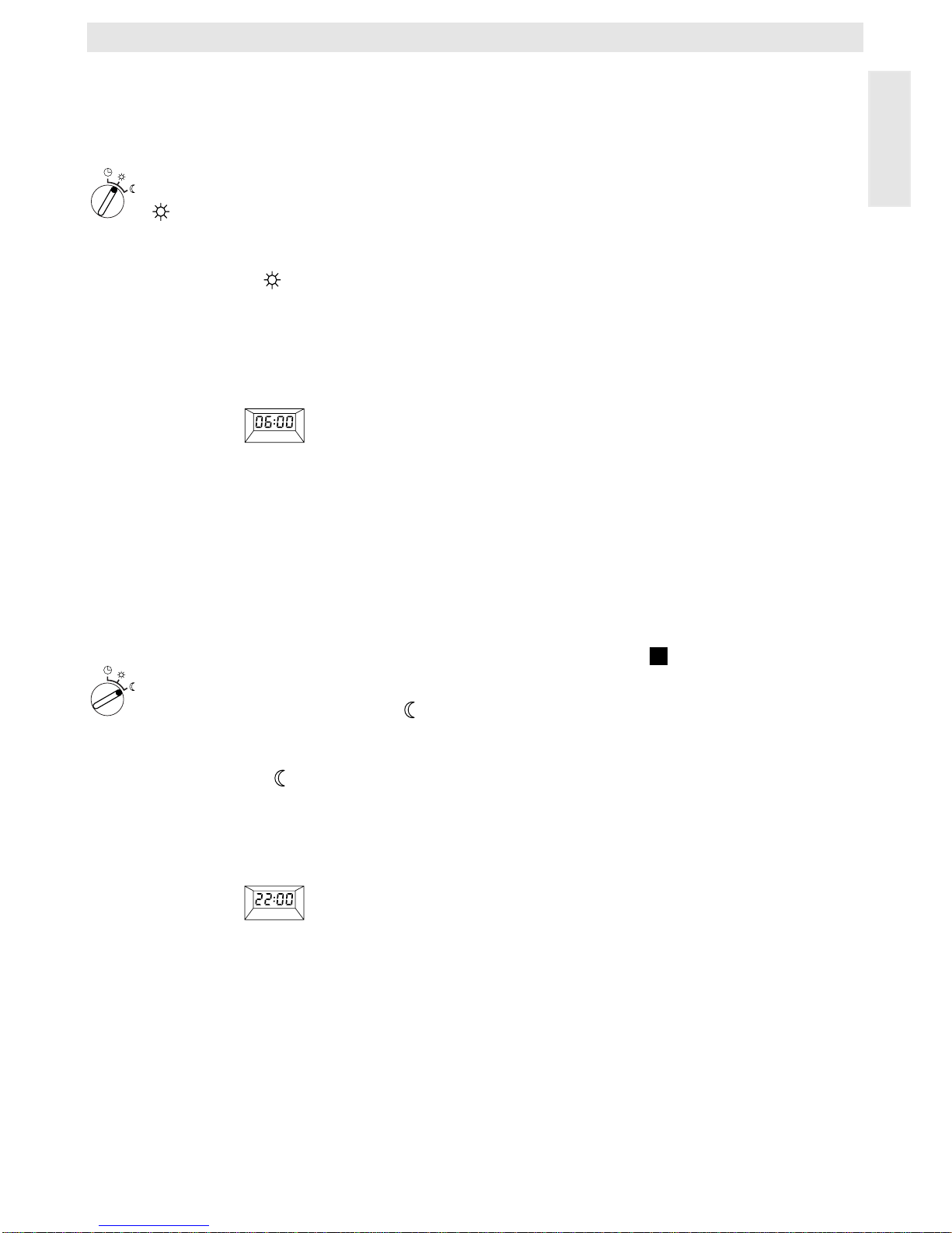
Setting the starting time for heating
()
The regulator is automatically set to the programming mode when the lid is opened. Set
the control knob (n) to the position (start
heating).
The display (e) shows the pre-set starting time
(at initial operation or power failure over a
longer period the starting time pre-set by the
factory):
The required starting time is set by depressing
the buttons
“-” (o) or “+” (p) .
Briefly depressing the button alters the starting time by 10 minutes, when the button is depressed for a longer period the time runs faster forward or backward.
When no more alterations are necessary
close the lid.
Setting the starting time for the
economical operating mode ( )
The regulator is automatically set to the programming mode when the lid is opened. Set
the control knob (n) to .
The display (e) shows the pre-set starting time
for economical operating mode (at initial operation or power failure over a longer period the
starting time pre-set by the factory):
The required starting time is set by depressing
the buttons
“-” (o) or “+” (p) .
Briefly depressing the button alters the starting time for economical operation mode by 10
minutes, when the button is depressed for a
longer period the time runs faster forward or
backward.
When no more alterations are necessary
close the lid.
6.3 Operating reserve
The time switch has an operating reserve of
approx. 2 hours after having been in continuous operation for at least one day. In case of
a power failure the display is no longer functioning. If the power supply returns within the
operating reserve period the display of the
time and the starting times for standard heating mode and economical operating mode will
be re-activated.
Take care that the power supply is never interrupted for longer than 2 hours (do not
switch off the heating system in the summer
but select a low temperature at the regulator;
see chapter 6.1.2 tips for continuous heating).
6.4 Setting the summer and the standard
times
Proceed as described in the chapter “setting
the time”!
Do not alter the settings “start heating” and
“start economical operation”!
6.5 Brief operating instructions
The brief operating instructions are in the
compartment at the right side of the base
where all important functions are briefly described (illustration ).
6.6 Regulator with connected room tem-
perature sensor RF 1 (accessory)
If a room temperature sensor RF 1 is connected the built-in sensor in the regulator is ineffective. Now the temperature conditions surrounding the external room temperature sensor are decisive.
Use the external room temperature sensor when the mounting location of the regulator has unfavourable measuring conditions
and which are not applicable for the entire
house e.g. insolation, a tiled stove nearby, etc.
6.7 Regulator with connected remote
control switch (by customers)
With this remote control switch (not included
in the Junkers delivery range) the heating system can be activated from afar.
The most common application is probably the
use of a telephone commander. With this appliance the heating system can be switched
on via any telephone with aid of a personal
identification code.
☞
Tip
☞
Tip
2
☞
Tip
Page 10
English
10
TR 100
Before leaving the house the regulator is set
to the mode required at return (automatic operation mode or continuous heating operation).
Then the switching contact of the remote control switch is deactivated, the regulator is operating in the economical operating mode. The
respective red control light (l) is off.
Appears simultaneously in the display:
If the switching contact is activated (e.g. by a
coded telephone signal) the regulator operates in the pre-set operating mode.
It will be warm in the house late at night/
early in the morning if the regulator is set to
the position (continuous heating) (g) before
leaving the house, and the switch is deactivated afterwards. Do not forget to set the regulator back to ”automatic operating mode“ after
returning to the house.
If the house is left for a longer period you
should consider that it could become a lot
cooler (walls could cool down etc.) and therefore it will take a longer time to heat up. Switch
the heating system on in time.
7 Regulator Malfunction Message
Malfunction remote indicator
(not available with all heating systems)
For heating equipment with Bosch Heatronic,
a malfunction in the heating eequipment is
routed to the regulator.
If the heating system has a malfunction message the control light will indicate (l).
Note: In this case please proceed as stat-
ed in the operating instructions of
the heating unit or contact your local expert for heating systems.
☞
Tip
Page 11

English
TR 100
11
8 General Information
... and hints on saving energy:
When the regulator settings are altered the
regulator reacts with a time lag. Every 20 seconds the processor compares all desired and
actual values and carries out all necessary
corrections with the necessary speed.
The room in which the room temperature regulator is mounted (control room) determines
the temperature for all other rooms.
I.e. the room temperature in the control room
acts as a control input for the entire heating
network.
For this reason all thermostat regulated radiators located in the control room must be
opened completely at all times. Otherwise the
thermostat valves would reduce the heat supply although the regulator constantly requires
more heat (see also chapter 4.1).
If in the adjoining rooms a lower temperature
is wanted or if the radiator should be turned off
completely, the (thermostatic) radiator valves
must be set accordingly.
Since the room where the room temperature
regulator is mounted acts as a control room,
any external heating sources (e.g. insolation,
tiled stove, etc.) can result in insufficient
heating of the remaining rooms (the radiators
stay cold). In order to avoid this the room
temperature sensor RF 1 can be used
according to the notes in chapter 2.2,
chapter 5.1 and chapter 6.6.
When the room temperature is reduced during the day or during the night a lot of energy
can be saved.
If the room temperature is reduced by 1 K
(°C) this can save up to 5% of energy.
It is not recommended to let the temperature
of daily heated rooms drop below +15°C.
When the room is heated up again the comfortableness is diminished by the walls which
are cooled down. So if one wants a real comfortable room temperature the regulator must
be turned up and so a lot more energy is used
up than is in case of an even heat supply.
If the building has good thermal insulation it is
possible that the set economic temperature is
not reached. But even in this case energy is
saved since the heating system is not activated.
In this case the starting time for economical
operating mode can be set earlier.
Do not let windows stand ajar for airing the
rooms since this would constantly withdraw
heat from the room without improving the air in
the room considerably. Do avoid continuous
airing!
It is better to air the room briefly but properly
(open the windows completely).
Set the temperature regulator to a lower value
during airing.
Page 12
English
12
TR 100
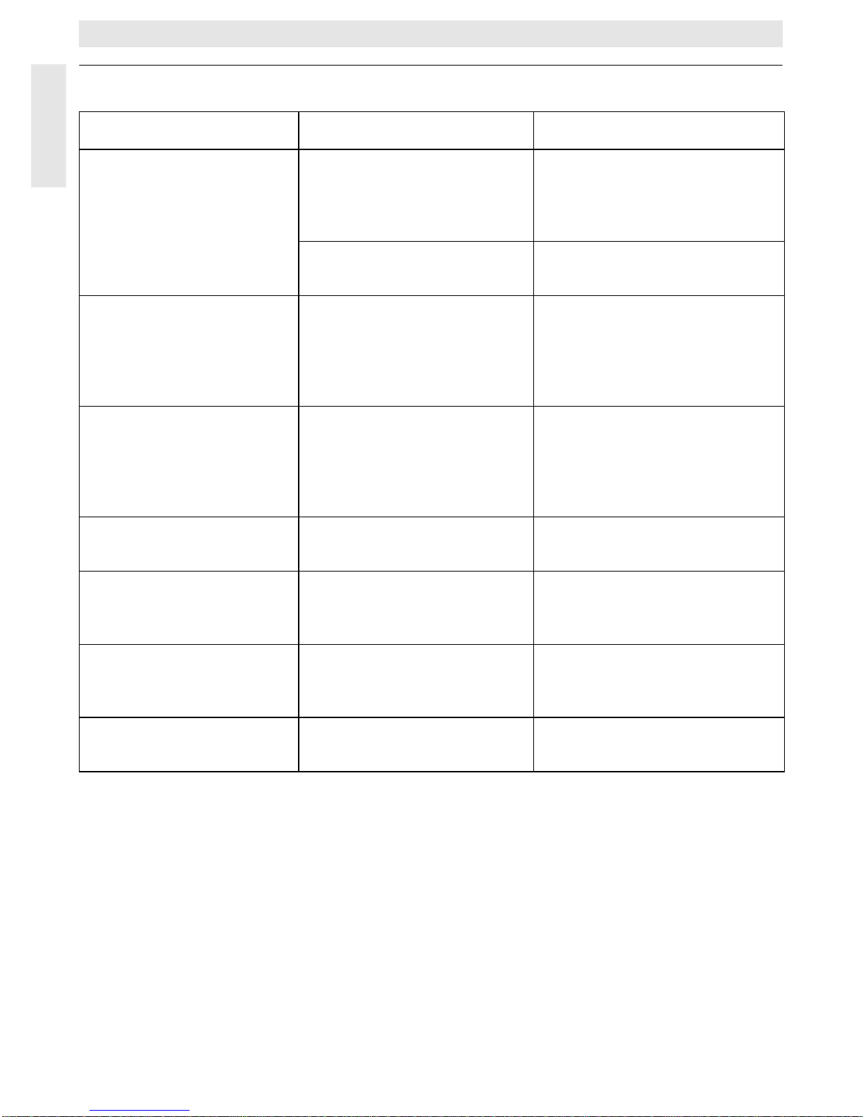
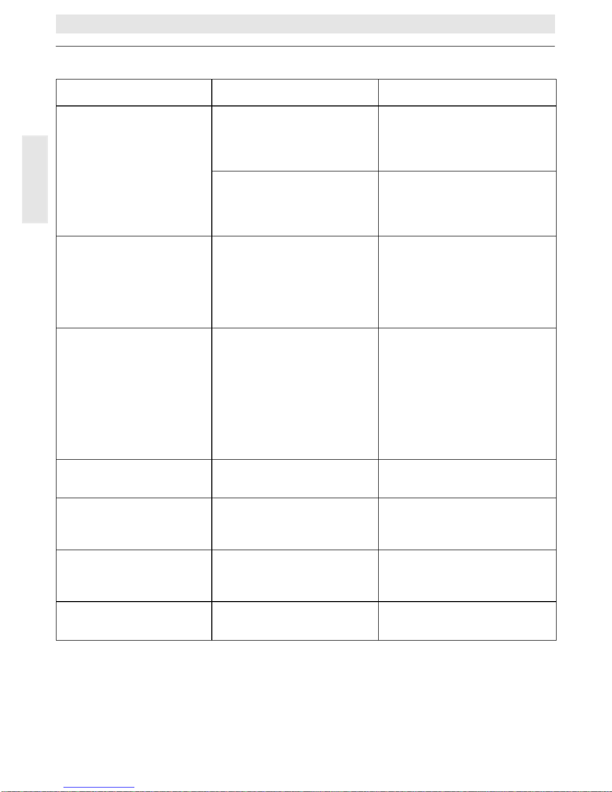
9 Elimination of malfunctions
Malfunction Cause Elimination
the set room temperature
is not reached
thermostat valve(s) are
installed in the room where
the regulator is mounted
have the thermostat valve
replaced by a hand valve or
completely open the thermostat valve(s)
the flow temperature of the
heating unit is set too low
set the flow temperature to a
higher value
the pre-set room temperature is exceeded
the mounting location of the
regulator is inappropriate,
e.g. outside wall, close to a
window, draught,...
select a more appropriate
mounting location (see chapter mounting) or use an external temperature sensor
(accessory)
too high variation in room
temperature
temporary influence of
external heating sources on
the regulator e.g. by insolation, room lighting, TV, fireplace, etc.
select a more appropriate
mounting location (see chapter mounting) or use an external temperature sensor
(accessory)
rise in temperature
instead of reduction
the time of day is set incorrectly at the time switch
check the setting
too high room temperature in economic operating mode
high regenerative capacity
of the building
select an earlier starting time
for economic operating mode
wrong or no regulation wrong wiring of the regulator check the wiring according to
the circuit diagram and correct
if necessary
no display or the colon is
not indicating
very short power failure switch off and on the heating
unit main switch
Page 13

Po polsku
TR 100
13
1 Wskazówki bezpieczeµstwa
Regulator mo†e byç wy∆åcznie stosowany
z wymienionymi ogrzewaczami gazowymi
firmy Junkers. Nale†y przy tym
przestrzegaç odpowiedni plan przy∆åczeµ.
Nie wolno pod∆åczaç regulatora
bezpo∂rednio do sieci 230 V.
Przed monta†em regulatora nale†y
przerwaç zasilanie (230 V, 50 Hz) do
ogrzewacza.
Regulator nie nadaje si™ do monta†u w
pomieszczeniach wilgotnych.
2 Zastosowanie
Regulator TR 100 jest pokojowym
regulatorem temperatury wyposa†onym w
cyfrowy zegar sterujåcy ((program dzienny,
punkt ogrzewania i wyƌczania; takie same dla
wszystkich dni tygodnia) przeznaczonym do
regulacji ogrzewaczy gazowych firmy
Junkers.
Model TR 100 zalecany jest do ogrzewania
pomieszczeµ o powierzchniach do 80 m
2
i
odpowiada odpowiednim przepisom.
TR 100 nie poleca si™ jako pokojowego
regulatora temperatury do systemów z
ogrzewaniem pod∆ogowym i klimatyzacjå. W
takich pomieszczeniach zaleca si™
stosowanie regulacji pogodowej.
2.1 Wyposa†enie
Do wyposa†enia modelu TR 100 nale†y
pokojowy regulator temperatury z wsuni™tå
skróconå wersjå instrukcji obs∆ugi (szkic ).
2.2 Osprz™t dodatkowy
Do modelu TR 100 dostarczany jest
zewn™trzny pokojowy czujnik temperatury
RF 1. Jego zainstalowanie wydaje si™
sensowny w takich okoliczno∂ciach, kiedy
miejsce monta†u regulatora nie nadaje si™ do
pomiarów temperatury (patrz rozdzia∆ 4).
W dalszej kolejno∂ci mo†e byç pod∆åczony
zdalny wƌcznik (np. w formie komandera
telefonicznego (patrz rozdzia∆ 6.7).
Zdalny w∆åcznik musi posiadaç potencjalnie
wolny kontakt, który nadaje si™ do napi™cia
5 V DC.
3 Dane technicznen
4 Monta† regulatora
Przed monta†em regulatora nale†y
przerwaç zasilanie (230 V, 50 Hz) do
ogrzewacza.
4.1 Wybór miejsca monta†u
Bardzo wa†nym czynnikiem wp∆ywajåcym na
jako∂ç regulacji TR 100 jest optymalny wybór
miejsca monta†u. Pomieszczenie, w którym
zamontowany b™dzie regulator, powinno byç
reprezentatywne (pod wzgl™dem
temperatury) dla ca∆ego systemu centralnego
ogrzewania. Zainstalowane w tym
pomieszczeniu grzejniki nie powinny byç
wyposa†one w zawory z g∆owicami
termostatycznymi. Zaleca si™ stosowanie w
tym miejscu zaworów sterowanych r™cznie z
wst™pnå regulacjå, tak aby wydajno∂ç
TYP Przyƌczenie
elektryczne
Aktywny
wskaçnik
zak∆óceµ
ZE/ZWE .. K... Szkic nie
ZE/ZWE .. - 1 K... Szkic nie
ZE/ZWE .. - 2 K... Szkic nie
ZE/ZWE .. - 1 A... Szkic nie
ZE/ZWE .. - 2 A... Szkic nie
ZR/ZWR/ZSR...-3 Szkic nie
ZR/ZWR/ZSR...-4 Szkic nie
Ogrzewacze z
systemem
Bosch-Heatronic Szkic tak
9
9
9
10
10
10
10
11
2
Wymiary urzådzenia
patrz szkic
Napi™cie znamionowe 24 V DC
Pråd znamionowy 0,02 A
Zakres regulacji
temperatury
5…30 °C
Sygna∆ na wyj∂ciu
regulatora
regulacja ciåg∆a,
2,5…21 V DC
Dopuszczalna
temperatura otoczenia 0…+40 °C
Rezerwa pracy ok. 2 godzin
Klasa ochrony IP 20
3
Page 14

Po polsku
14
TR 100
grzejników w pomieszczeniu monta†owym
TR 100 mog∆a byç regulowany tylko w bardzo
wåskim zakresie.
Jako miejsce monta†u najlepiej wybraç ∂cian™
wewn™trznå i uwa†aç, aby pozbawiona ona
by∆a dodatkowych czynników fa∆szujåcych
odczyt temperatury przez regulator
(nagrzewanie przez promienie s∆oneczne,
kumulacja ciep∆a pochodzåcego z grzejników,
wych∆odzenie ∂ciany przez przeciågi itp.)
Poni†ej i powy†ej regulatora nale†y
pozostawiç wystarczajåco du†o miejsca, tak
aby cyrkulacja powietrza nie by∆a
ograniczona, a samo powietrze mog∆o
swobodnie przedostaç si™ przez otwory
znajdujåce si™ w obudowie urzådzenia
(zakreskowana powierzchnia na rysunku ).
Je∂li wszystkie wy†ej wymienione warunki nie
mogå byç spe∆nione, zaleca si™
zainstalowanie i monta† w odpowiednim
miejscu zewn™trznego czujnika temperatury
RF 1 (osprz™t dodatkowy).
W momencie pod∆åczenia zewn™trznego
czujnika temperatury RF 1 zamontowany w
regulatorze czujnik zostaje automatycznie
odƌczony.
4.2 Monta† regulatora
• Zdjåç górnå cz™∂ç (a) od podstawki (b),
wcisnåç boczne haczyki (b1) znajdujåce si™
w podstawie i ∂ciågnåç górnå cz™∂ç (a)
regulatora (szkic ).
• Podstaw™ (b) mo†na zamontowaç w
nast™pujåcy sposób:
– za pomocå dwóch wkr™tów (c) do
typowej puszki podtynkowej (d) o
∂rednicy 55 mm,
lub
– bezpo∂rednio na ∂cianie, wiercåc cztery
otwory i zamocowaç 4 ko∆kami
rozporowymi (6 mm) oraz wkr™tami
(3,5 mm) z p∆askå g∆ówkå (szkic );
zwróciç przy tym uwag™ na prawid∆owy
kierunek monta†u (czytelne oznaczenie
zacisków)!
• dokonaç odpowiedniego pod∆åczenia
elektrycznego (patrz rozdzia∆ 5).
• nasadziç górnå cz™∂ç regulatora (a).
4.3 Monta† osprz™tu dodatkowego
Osprz™t dodatkowy tj. zewn™trzny czujnik
temperatury RF 1 i zdalny w∆åcznik (je∂li
przewidziane do monta†u) nale†y zabudowaç
wzgl. pod∆åczyç zgodnie z odpowiednimi
przepisami i wskazówkami.
5 Podƌczenie elektryczne
Stosowaç nast™pujåce przekroje przewodu
∆åczåcego regulator TR 100 z kot∆em:
Przy uwzgl™dnieniu obowiåzujåcych
przepisów nale†y stosowaç do pod∆åczenia co
najmniej kable elektryczne typu NYM.
W celu wyeliminowania niekorzystnych
oddzia∆ywaµ indukcyjnych, wszystkie
przewody regulatora 24 V (pråd pomiarowy)
nale†y prowadziç w oddaleniu (co najmniej
100 mm) od kabli zasilajåcych (230 V lub
400 V).
W przypadku, gdy mo†na spodziewaç si™
dodatkowych zewn™trznych zak∆óceµ
indukcyjnych spowodowanych np. przez
kable zasilajåcymi o du†ym napi™ciu,
przewody jezdne, trafostacje, sygna∆y
radiowe lub telewizyjne, amatorskie
radiostacje, kuchenki mikrofalowe itp.,
przewody nale†y zaekranowaç.
Nale†y przestrzegaç odpowiedni plan
po∆åczeµ elektrycznych (szkic do ):
5.1 Pod∆åczenie elektryczne osprz™tu
dodatkowego
Zewn™trzny czujnik temperatury RF 1 (je∂li
ma byç zamontowany) powinien byç
podƌczony zgodnie ze szkicem .
W razie konieczno∂ci przewody czujnika RF 1
mogå byç przed∆u†one skr™conym kablem
dwu†y∆owym. W ten sposób mo†na zapewniç,
†e warto∂ci pomiarowe czujnika nie b™då
przek∆amywane.
4
5
6
D∆ugo∂ç przewodu
do 20 m 0,75 mm
2
do 1,5 mm
2
D∆ugo∂ç przewodu
do 30 m 1,0 mm
2
do 1,5 mm
2
Wi™cej ni† 30 m 1,5 mm
2
9 11
7
Page 15
Po polsku
TR 100
15
W∆åcznik zdalnie sterowany (je∂li fabrycznie
zabudowany) pod∆åczyç zgodnie ze
schematem na szkicu . Odpowiednie
wymagane warunki podane så w rozdziale
patrz rozdzia∆ 2.2 osprz™t dodatkowy.
Przy zamkni™tym kontakcie w∆åcznika
zdalnego sterowania ogrzewanie przestawia
si™ na tryb "nocny" (oszcz™dny), a na
wskaçniku pojawia si™ "F". Przy otwartym
kontakcie przej™ty zostaje ustawiony
pierwotnie na regulatorze tryb pracy
(szkic ).
6 Obs∆uga
Model TR 100 posiada kilka elementów
obs∆ugowych, które po instalacji i uruchomieniu
b™då u†ywane bardzo rzadko.
Z tego powodu wszystkie elementy obs∆ugowe, z
których korzystamy bardzo rzadko, zamkni™te så
specjalnå klapkå przesuwnå.
Wszuystkie widoczne elementy obs∆ugowe
widoczne po zamkni™ciu klapki nale†å do tzw.
"pierwszego poziomu obs∆ugi". Wszystkie inne
tworzå tzw. "drugi poziom obs∆ugi".
Wszystkie stany specjalne regulatora
pokazywane så przez odpowiednie lampki
kontrolne jak równie† wskazania zak∆óceµ lub
awarii (tylko przy ogrzewaczach z systemem
Bosch Heatronic).
Przy zamkni™tej klapie wskazywany jest aktualny
czas.
6.1 "Pierwszy poziom obs∆ugi" (szkic )
6.1.1 Pokr™t∆o (k)
Za pomocå pokr™t∆a (k) ustawiana jest
temperatura pomieszczenia, na którå
regulator w normalnym trybie ogrzewania
powinien regulowaç.
Regulator reguluje wtedy zawsze do takiej
temperatury, kiedy pali si™ czerwona lampka
kontrolna (l).
Je∂li pokr™t∆o (k) znajduje si™ na "5", nie
za∂wici si™ lampka kontrolna (l). Regulator
reguluje wtedy do temperatury ok. 5 °C i
zapewnia tym samym ochron™ przed mrozem
w pomieszczeniu. Oznacza to, †e ogrzewanie
jest wyƌczone.
6.1.2 Przeƌczniki trybu pracy
Tryb automatyczny
Podstawowym ustawieniem regulatora jest
automatyczny tryb pracy.
Tryb automatyczny oznacza automatyczne
prze∆åczanie pomi™dzy okresami temperatury
"dziennej" (normalnej), a okresami
temperatury "nocnej" (obni†onej) wg.
programu nastawionego na zegarze
cyfrowym (e).
Regulator obs∆uguje ogrzewanie w trybie
normalnym (dziennym) do ustawionej na
pokr™tle (k) temperatury, czerwona lampka
kontrolna (l) ∂wieci si™ ca∆y czas.
Regulator obs∆uguje ogrzewanie w trybie
oszcz™dnym (nocnym) do ustawionej
temperatury "nocnej", czerwona lampka
kontrolna (l) nie ∂wieci si™. (Ustawianie
temperatury "nocnej" patrz rozdzia∆ 6.2.1)
Wskazówka: Ka†de opuszczenie trybu
automatycznego pokazywane
jest przez lampk™ kontrolnå
Ka†dorazowo mo†na
ponownie przywróciç tryb
automatyczny.
Tryb pracy ciåg∆ej (g)
Naci∂ni™cie przycisku (g) w∆åcza tryb pracy
ciåg∆ej.
Regulator obs∆uguje pomieszczenie na
podstawie nastawy na pokr™tle (k)
temperatury "dziennej" (normalnej).
Czerwona lampka kontrolna (f) ∂wieci si™.
Równie† czerwona lampka kontrolna (l)
∂wieci si™ (z wyjåtkiem ustawienia pokr™t∆a (k)
w pozycji "5").
Ustawiony na zegarze tryb "nocny"
(oszcz™dny) jest ignorowany.
Tryb pracy "ogrzewanie ciåg∆e" pozostaje
utrzymany tak d∆ugo a†:
• ponownie naci∂ni™ty zostanie przycisk
(g); ponownie zostanie wtedy w∆aczony
tryb automatyczny
lub
• wci∂ni™ty zostanie przycisk (h); ustawiony
zostanie wtedy tryb oszcz™dny
8
8
1
25
15
5
3010
20°C
Page 16
Po polsku
16
TR 100
W obu przypadkach ga∂nie czerwona lampka
kontrolna (f) a regulator ogrzewa do
odpowiednio w∆a∂ciwej temperatury.
Wcisnåç ten przycisk, je∂li wyjåtkowo
idziecie póçniej spaç do ∆ó†ka (np. party).
Potem ponownie prze∆åczyç na tryb
automatyczny.
Równie† w czasie choroby tryb ogrzewania
ciåg∆ego mo†e byç przyjemny. Nie nale†y
jednak równie† wtedy zapomnieç o
ponownym przeƌczeniu na tryb
automatyczny.
Podczas urlopu zimowego lub w lecie mo†na
wybraç na d∆u†szy czas ni†szå temperatur™.
W tym celu nale†y nacisnåç przycisk
ogrzewania ciåg∆ego i dodatkowo obni†yç
temperatur™ na pokr™tle (k).
Przycisk "trybu oszcz™dnego"
(nocnego) (h)
Wci∂ni™cie przycisku (h) uruchamia tryb
oszcz™dny.
Regulator obs∆uguje do ustawionej na
pokr™tle "temperatury nocnej" (regulacja
temperatury nocnej patrz rozdzia∆ 6.2.1).
˝ó∆ta lampka kontrolna (i) ∂wieci si™.
Czerwona lampka kontrolna (l) nie ∂wieci si™.
Ustawiony na zegarze tryb "normalny" jest
ignorowany.
Tryb pracy "ogrzewanie oszcz™dne"
pozostaje utrzymany tak d∆ugo a†:
• osiågni™ta zostanie pó∆noc (godzina 00.00)
lub
• ponownie naci∂ni™ty zostanie przycisk
(h); ponownie zostanie wtedy wƌczony
tryb automatyczny
lub
• wci∂ni™ty zostanie przycisk (g);
ustawiony zostanie wtedy tryb ogrzewania
ciåg∆ego.
In ka†dym z przedstawionych przypadków
ga∂nie †ó∆ta lampka kontrolna (i) a regulator
ogrzewa do odpowiednio w∆a∂ciwej
temperatury.
Nale†y stosowaç t™ funkcj™, je∂li
czasami opuszczacie Paµstwo mieszkanie
(np. na czas zakupów) i mieszkanie nie musi
byç ogrzewane. Zaraz po powrocie nale†y
ponownie wcisnåç przycisk (h), regulator
zaczyna ponownie pracowaç w trybie
automatycznym i ogrzewa do odpowiedniej
w∆a∂ciwej temperatury.
Je∂li opuszczacie Paµstwo mieszkanie
wieczorem lub k∆adziecie si™ wcze∂niej spaç,
nale†y wcisnåç przycisk (h). Regulator o
pó∆nocy koµczy ogrzewanie w trybie
oszcz™dnym (nocnym) i grzeje rano jak
zwykle w trybie automatycznym.
6.2 "Drugi" poziom obs∆ugi
"Drugi" poziom obs∆ugowy dost™pny jest po
otwarcie klapki.
6.2.1 Pokr™t∆o "temperatura
oszcz™dna" (m)
Na pokr™tle (m) ustawiana jest temperatura
w pomieszczeniu, do której regulator
obs∆uguje w trybie automatycznym przy
"oszcz™dzaniu" i trybie "nocnym" (h).
6.2.2 Informacje ogólne o zegarze
Zegar umo†liwia jeden raz dziennie
automatycznie w∆åczyç i wy∆åczyç ogrzewanie
w wybranym czasie. Oba punkty czasowe så
takie same dla wszystkich dni.
Nastawianie zegara ( )
Na wskaçniku (e) pojawia si™ aktualny czas (w
czasie uruchomienia lub po d∆u†szym
przerwaniu dop∆ywu prådu pojawia si™
ustawienie fabryczne):
Po otwarciu klapki ustawiany jest
automatycznie tryb programowania. Obróciç
pokr™t∆o (n) na symbol " ".
Ustawienie czasu nast™puje poprzez
naci∂ni™cie przycisków "-" (o) lub "+" (p).
Krótkie naci∂ni™cie przestawia zegar o 1
minut™, przy d∆u†szym naciskaniu nast™puje
szybkie przeskakiwanie czasu do przodu lub
ty∆u. Sekundy ustawiane så przy tym na "0".
☞
Tip
☞
Tip
10
20
25
30
15°C
5
Page 17
Po polsku
TR 100
17
Po zwolnieniu nacisku na przycisk zegar
biegnie dalej. Je∂li przycisk nie jest wciskany,
zegar równie† biegnie dalej.
Czasy przed godzinå 12.00 (po∆udnie)
pozwalajå si™ przy u†yciu przycisku "-" (o)
szybciej ustawiç.
Zamknåç klapk™ po dokonaniu wszystkich
niezb™dnych zmian.
Ustawienie poczåtku
ogrzewania ( )
Po otwarciu klapki ustawiany jest
automatycznie tryb programowania. Obróciç
pokr™t∆o (n) na symbol " " (poczåtek
ogrzewania).
Na wskaçniku (e) pojawia si™ ostatnio
ustawiony poczåtek ogrzewania ((w czasie
uruchomienia lub po d∆u†szym przerwaniu
dop∆ywu prådu pojawia si™ ustawienie
fabryczne):
W∆a∂ciwy poczåtek ogrzewania ustawiany jest
za pomocå przycisków "-" (o) lub "+" (p).
Krótkie naci∂ni™cie przestawia punkt
rozpocz™cia ogrzewania o 10 minut™, przy
d∆u†szym naciskaniu nast™puje szybkie
przeskakiwanie punktu czasowego do przodu
lub ty∆u.
Zamknåç klapk™ po dokonaniu wszystkich
niezb™dnych zmian.
Ustawienie poczåtku
oszcz™dzania ( )
Po otwarciu klapki ustawiany jest
automatycznie tryb programowania. Obróciç
pokr™t∆o (n) na symbol " ".
Na wskaçniku (e) pojawia si™ ostatnio
ustawiony poczåtek oszcz™dzania ((w czasie
uruchomienia lub po d∆u†szym przerwaniu
dop∆ywu prådu pojawia si™ ustawienie
fabryczne):
W∆a∂ciwy poczåtek oszcz™dzania ustawiany
jest za pomocå przycisków "-" (o) lub "+" (p).
Krótkie naci∂ni™cie przestawia punkt
rozpocz™cia oszcz™dzania o 10 minut™, przy
d∆u†szym naciskaniu nast™puje szybkie
przeskakiwanie punktu czasowego do przodu
lub ty∆u.
Zamknåç klapk™ po dokonaniu wszystkich
niezb™dnych zmian.
6.3 Rezerwa pracy
Zegar po jednodniowym trybie pracy
dysponuje rezerwå energii podtrzymujåcej
prac™ na ok. 2 godziny. Po wy∆åczeniu
dop∆ywu prådu ga∂nie wskaçnik. Je∂li
zasilanie zostanie w∆åczone w ciågu okresu
rezerwy pracy, zachowane zostajå ustawienia
czasu, poczåtku ogrzewania i oszcz™dzania.
Uwa†aç, aby zanik dop∆ywu energii
elektrycznej nie trwa∆ d∆u†ej ni† 2 godziny (nie
wy∆åczaç ogrzewania w lecie, ale wybraç
ni†szå temperatur™; patrz rozdzia∆ 6.1.2
Wskazówka do ogrzewania ciåg∆ego).
6.4 Ustawianie czasu letniego/zimowego
Wykonaç procedury jak w rozdziale
"Ustawianie zegara"!
Nie zmieniaç punktów czasowych
"rozpocz™cie ogrzewania" i rozpocz™cie trybu
oszcz™dzania".
6.5 Skrócona instrukcja obs∆ugi
W skrytce po prawej stronie znajduje si™
skrócona instrukcja obs∆ugi, w której opisane
så wszystkie wa†ne informacje (szkic ).
6.6 Regulator z podƌczonym czujnikiem
temperatury pomieszczenia RF 1
(osprz™t dodatkowy)
Przy podƌczonym czujniku temperatury
pomieszczenia RF 1 nie dzia∆a zainstalony
czujnik w regulatorze. Dlatego miarodajnymi
wynikami så pomiary w obszarze dzia∆ania
zewn™trznego czujnika temperatury.
Zastosowaç czujnik temperatury, je∂li w
miejscu monta†u regulatora panujå
niekorzystne warunki pomiarowe, które nie så
reprezentatywne (miarodajne) dla ca∆ego
mieszkania np. nagrzewanie przez promienie
s∆oneczne, kumulacja ciep∆a z pieca
kaflowego, wych∆odzenie ∂ciany przez
przeciågi itp.
☞
Tip
☞
Tip
2
☞
Tip
Page 18
Po polsku
18
TR 100
6.7 Regulator z podƌczonym zdalnym
wƌcznikiem (fabrycznie)
Poprzez ten dodatkowy wƌcznik (nie ma go w
programie dostaw Junkersa) ogrzewanie
mo†e byç w∆åczane na odleg∆o∂ç.
Najcz™stszym zastosowaniem jest pos∆u†enie
si™ komanderem telefonicznym. Dzi™ki temu
mo†liwe jest w∆åczenie ogrzewania poprzez
ka†dy telefon po podaniu osobistego kodu
sterujåcego.
Przed opuszczeniem domu nale†y ustawiç na
regulatorze tryb pracy, w jakim mieszkanie
ma byç ogrzewane po powrocie (tryb
automatyczny lub ogrzewanie ciåg∆e).
Po tym zamkni™ty zostaje w∆åcznik zdalnie
sterowanego wƌcznika, regulator pracuje w
trybie "oszcz™dzania", czerwona lampka
kontrolna (l) nie pali si™. Jednocze∂nie na
wskaçniku pojawia si™ symbol:
Je∂li w∆åcznik zostanie otwarty (np. poprzez
zakodowany sygna∆ telefoniczny), regulator
pracuje wg. wcze∂niej nastawionego
programu.
Mieszkanie jest równie† póçnym
wieczorem/wczesnym rankiem przyjemnie
ciep∆e, je∂li ustawicie Paµstwo regulator przed
opuszczeniem domu w pozycj™
(ogrzewanie ciåg∆e) (g) i dopiero wtedy
zakmniecie w∆åcznik. Nie nale†y jednak
zapomnieç ustawiç regulator po powrocie na
tryb automatyczny.
W czasie d∆u†szej nieobecno∂ci nie nale†y
zapominaç, †e mieszkanie (∂ciany itd.) så
silnie wych∆odzone i potrzebujå d∆u†szego
nagrzewania. Odpowiednio wcze∂nie nale†y
dlatego w∆åczyç ogrzewanie.
7 Komunikaty regulatora
Wskaçnik uszkodzenia/b∆™du
(nie we wszystkich urzådzeniach
grzewczych)
W modelach ogrzewaczy wyposa†onych w
system Bosch Heatronic uszkodzenie/bƌd
przekazywany jest z ogrzewacza do
regulatora.
Przy uszkodzeniu ogrzewacza miga lampka
kontrolna (l).
Wskazówka: w takim przypadku nale†y
post™powaç zgodnie ze
wskazówkami zawartymi w
instrukcji obs∆ugi ogrzewacza
lub nale†y poinformowaç
odpowiedzialnego fachowca z
autoryzowanego serwisu.
☞
Tip
Page 19
Po polsku
TR 100
19
8 Wskazówki ogólne
... i porady oszcz™dnego gospodarowania
energiå:
Podczas zmiany nastawieµ regulatora
regulator reaguje z odpowiednim
opóçnieniem czasowym. Procesor co 20
sekund porównuje wszystkie warto∂ci
rzeczywiste i nastawione i dokonuje po tym
odpowiednie korekty.
Pomieszczenie (pomieszczenie
reprezentatywne), w którym zainstalowany
jest regulator, ustala temperatur™ dla innych
pomieszczeµ w mieszkaniu.
Oznacza to, †e temperatura w pomieszczeniu
reprezentatywnym jest traktowana jako
warto∂ç odniesienia dla ca∆ej sieci grzewczej.
Z tego te† powodu je∂li w pomieszczeniu
reprezentatywnym zainstalowane så grzejniki
wyposa†one w g∆owice z zaworami
termostatycznymi muszå byç one zawsze
ca∆kowicie otwarte. W przeciwnym wypadku
g∆owice z zaworami termostatycznymi d∆awiå
dop∆yw ciep∆a, mimo †e regulator ca∆y czas
domaga si™ wi™cej energii cieplnej (patrz
rozdzia∆ 4.1).
Je∂li w innych pomieszczeniach †yczymy
sobie ni†szå temperatur™ lub grzejniki majå
byç ca∆kowicie wy∆åczone, to g∆owice z
zaworami termostatycznymi nale†y
odpowiednio ustawiç i wyregulowaç.
Poniewa† pomieszczenie, w którym
zainstalowany jest regulator temperatury,
dzia∆a jako pomieszczenie reprezentatywne,
doj∂ç mo†e poprzez tzw. ciep∆o obce (np.
nagrzewanie przez promienie s∆oneczne,
kumulacja ciep∆a z pieca kaflowego itp.) do
niedostatecznego nagrzania pozosta∆ych
pomieszczeµ (ogrzewanie pozostaje zimne).
Aby temu zapobiec nale†y zastosowaç jako
osprz™t dodatkowy czujnik temperatury w
pomieszczeniu RF 1, zgodnie ze
wskazówkami zawartymi w patrz rozdzia∆ 2.2,
patrz rozdzia∆ 5.1 i patrz rozdzia∆ 6.6).
Poprzez redukcj™ temperatury pomieszczenia
przez dzieµ i noc mo†na zaoszcz™dziç du†o
energii.
Obni†enie temperatury o 1 K (°C) powoduje
ograniczenie w zu†yciu energii o 5%.
Nie nale†y jednak sch∆adzaç codziennie
ogrzewanych pomieszczeµ poni†ej +15 °C.
Podczas nast™pnego ogrzewania
zmniejszony zostanie przez to wspó∆czynnik
komfortu poprzez wych∆odzone ∂ciany. Aby
mimo to "przyjemnie ogrzaç pomieszczenie",
cz™sto ustawiana jest wy†sza temperatura
pomieszczenia. Zu†ywane jest przez to
zdecydowanie wi™cej energii ni† przy
równomiernym, sukcesywnym i ciåg∆ym
ogrzewaniu.
W przypadku dobrej izoalcji cieplnej budynku
mo†liwe jest, †e temperatura "nocna"
nastawiona na regulatorze nie zostanie
osiågni™ta, gdy† b™dzie ona zbyt niska w
stosunku do sch∆adzania si™ pomieszczeµ.
Umo†liwi to znacznå oszcz™dno∂ç energii,
gdy† ogrzewacz przez ten czas jest
wyƌczony.
W takim przypadku poczåtek trybu "nocnego"
mo†na ustawiç wcze∂niej.
W celu wietrzenia nie zostawiaç na d∆u†szy
czas uchylonego okna.
Taka sytuacja powoduje szybkie sch∆odzenie
pomieszczenia bez specjalnej poprawy
cyrkulacji i wymiany powietrza w
pomieszczeniu. Unikaç nale†y wietrzeµ w
sposób ciåg∆y.
Lepiej wietrzyç krótko lecz intensywnie
(otworzyç ca∆kowicie okno).
Podczas przewietrzania regulator
temperatury ustawiç na ni†szå warto∂ç.
Page 20
Po polsku
20
TR 100
9 Zak∆ócenia i poszukiwanie przyczyn
Opis zak∆ócenia Przyczyna Usuni™cie zak∆ócenia
temperatura w
pomieszczeniu nie mo†e
osiågnåç nastawionej na
regulatorze warto∂ci
zainstalowane zawory
termostatyczne w
pomieszczeniu regulatora
zawory termostatyczne
wymieniç na r™czne lub
ca∆kowicie otworzyç zawory
termostatyczne
Termostat na ogrzewaczu
nastawiony na zbyt niskå
temperatur™ zasilania
uk∆adu c.o.
Ustawiç termostat na wy†szå
temperatur™ zasilania uk∆adu
c.o.
temperatura w
pomieszczeniu
przekracza nastawionå na
regulatorze warto∂ç
niew∆a∂ciwie dobrane
miejsce monta†u regulatora
(∂ciana zewn™trzna,
blisko∂ç okna, przeciågi itp.)
wybraç lepsze miejsce
monta†u (patrz rozdzia∆
Monta† regulatora lub
zainstalowaç zewn™trzny
czujnik temperatury (osprz™t
dodatkowy)
zbyt du†e wahania
temperatury w
pomieszczeniu
chwilowe oddzia∆ywanie
zewn™trznych çróde∆ ciep∆a
na regulator (np.
promieniowanie s∆oneczne,
ciep∆o pochodzåce z
o∂wietlenia pomieszczenia,
ciep∆o z urzådzeµ RTV,
oddzia∆ywanie ∂ciany
kominowej itp.)
wybraç lepsze miejsce
monta†u (patrz rozdzia∆
Monta† regulatora lub
zainstalowaç zewn™trzny
czujnik temperatury
wzrost temperatury
zamiast jej spadek
czas dnia na zegarze
niew∆a∂ciwie nastawiony
sprawdziç nastawienie czasu
w trybie "nocnym" zbyt
wysoka temperatura w
pomieszczeniu
dobra izolacja cieplna
budynku
wcze∂niej nastawiç tryb
"nocny"
niew∆a∂ciwa lub brak
regulacji
niew∆a∂ciwe pod∆åczenie
regulatora
podƌczenie regulatora
sprawdziç zgodnie z planem
pod∆åczeµ i ew. skorygowaç
brak wskazaµ lub
dwukropek nie miga
krótki zanik zasilania wy∆åczyç i ponownie w∆åczyç
gƗwny wƌcznik ogrzewacza
Page 21
âesky
TR 100
21
1 Bezpeãnostní pfiedpisy
Regulátor smí b˘t v˘hradnû pouÏit ve
spojení s uveden˘m plynov˘m kotlem
Junkers, dbejte na odpovídající schéma
zapojení.
V Ïádném pfiípadû nesmí b˘t regulátor
pfiipojen na síÈ 230 V.
Pfied montáÏí regulátoru musí b˘t
pfieru‰eno pfiívodní napûtí (230 V,
50 Hz) ke kotli.
Regulátor není vhodn˘ k montáÏi ve
vlhk˘ch prostorech.
2 PouÏití
TR 100 je regulátor teploty v místnosti s
digitálními spínacími hodinami (denní
program; spínací bod topení a poklesu; pro
v‰echny dny v t˘dnu stejné) k regulaci dole
uveden˘ch trvale fiízen˘ch plynov˘ch kotlÛ
Junkers.
TR 100 se doporuãuje pro obytné plochy do
ca. 80 m
2
a odpovídá zákonn˘m pfiedpisÛm.
Pro zafiízení s topením v podlaze nebo klima
podlahou nejsou regulátory teploty místnosti
jako je TR 100 vhodné, pro tato zafiízení
doporuãujeme regulaci fiízenou
povûtrnostními vlivy.
2.1 Obsah dodávky
K dodávce TR 100 patfií regulátor teploty
místnosti se vsunut˘m krátk˘m návodem k
obsluze (obr. ).
2.2 Pfiíslu‰enství
K TR 100 je moÏné dodat externí ãidlo
teploty v místnosti RF 1. Toto má smysl
pouÏít tehdy, je-li místo montáÏe regulátoru
nevhodné k mûfiení teploty (viz kap. 4).
Dále lze jako nadstavbu pfiipojit dálkov˘
spínaã (napfi. ve formû telefonního správce),
(viz kap. 6.7).
Dálkov˘ spínaã musí obsahovat
bezpotenciální kontakt, kter˘ je vhodn˘ pro
stejnosmûrné napûtí 5 V .
3 Technické údaje
4 MontáÏ
Pfied montáÏí regulátoru musí b˘t
zaji‰tûno pfieru‰ení pfiívodu proudu ke
kotli.
4.1 Volba místa montáÏe
DÛleÏité pro kvalitu regulátoru TR 100 je
volba vhodného místa montáÏe. Místnost,
kde se bude instalovat, musí b˘t vhodná pro
regulaci teploty celého topného systému. Na
zde instalovan˘ch topn˘ch tûlesech nesmí
b˘t namontovány Ïádné termostatické
ventily. Vyjma toho, Ïe by to byly instalované
ruãní ventily s pfiednastavením, aby se v˘kon
topného tûlesa v místnosti montáÏe dal co
moÏná nejpfiesnûji nastavit.
Jako místo montáÏe zvolte pokud moÏno
vnitfiní stûnu a dbejte na to, aby na regulátor
nepÛsobil prÛvan a tepelné paprsky (ani
zezadu jako napfi. trubkou, dutou stûnou
apod.)
TYP El.
zapojení
Dálkové
hlá‰ení
poruchy je
aktivní
ZE/ZWE .. K... obr. ne
ZE/ZWE .. - 1 K... obr. ne
ZE/ZWE .. - 2 K... obr. ne
ZE/ZWE .. - 1 A... obr. ne
ZE/ZWE .. - 2 A... obr. ne
ZR/ZWR/ZSR...-3 obr. ne
ZR/ZWR/ZSR...-4 obr. ne
kotle s Bosch
Heatronic obr. ano
9
9
9
10
10
10
10
11
2
Rozmûry pfiístroje
viz obr.
Jmenovité napûtí 24 V =
Jmenovit˘ proud 0,02 A
Rozsah regulace 5…30 °C
V˘stup regulace trval˘, 2,5…21 V DC
Dovolená teplota
okolí 0…+40 °C
Rezerva chodu ca. 2 hodiny
Druh ochrany IP 20
3
Page 22

âesky
22
TR 100
Pod a nad regulátorem musí b˘t k dispozici
dostateãnû místa, aby vzduch v místnosti
mohl bez zábran proudit vûtracími otvory
(‰rafovaná plocha na obr. ).
Pokud nejsou splnûny v‰echny v˘‰e
uvedené podmínky, pak se doporuãuje
pouÏít externí ãidlo teploty místnosti RF 1
(pfiíslu‰enství) a toto umístit na vhodném
místû.
Pfii pfiipojení ãidla teploty místnosti RF 1 se
automaticky vypne ãidlo zabudované v
regulátoru.
4.2 MontáÏ regulátoru
• horní ãást (a) uvolnûte ze soklu (b) takto:
postranní háky (b1) zatlaãte do soklu a
stáhnûte horní ãást (a) (obr. ).
• sokl (b) lze namontovat buì
– pomocí dvou ‰roubÛ (c) na normální
podomítkovou krabici (d) Ø 55 mm,
nebo
– pomocí 4 hmoÏdinek (6 mm) a ‰roubÛ
(Ø 3,5 mm) s ãoãkovou hlavou pfiímo
na stûnu (obr. );
pfiitom dbejte na správn˘ smûr montáÏe
(ãitelné popisy).
• elektrické pfiipojení vyveìte odpovídajícím
zpÛsobem (viz kap. 5).
• nasuÀte horní ãást regulátoru (a).
4.3 MontáÏ pfiíslu‰enství
Pfiíslu‰enství - ãidlo teploty místnosti RF 1 a
dálkov˘ spínaã (je-li k dispozici), namontujte
dle zákonn˘ch pfiedpisÛ a pfiíslu‰ného
pfiedpisu zabudování.
5 Elektrické pfiipojení
Od TR 100 ke kotli pouÏijte následující
prÛfiez vodiãÛ:
Pfii zohlednûní platn˘ch pfiedpisÛ musí b˘t
pro pfiipojení pouÏity minimálnû vodiãe typu
NYM.
V‰echna 24 V vedení (fiídící napûtí) musí
b˘t uloÏena oddûlenû od 230 V nebo 400 V
vedení, aby se neuplatnil Ïádn˘ vliv indukce
(minimální vzdálenost 100 mm).
Pokud lze oãekávat vnûj‰í vlivy indukce, jako
napfi. silnoproud˘ kabel, trolejové vedení,
trafostanice, rozhlasové, televizní ãi
amatérské vysílaãe, mikrovlnná zafiízení,
mûlo by b˘t vedení fiídícího signálu stínûné.
Dbejte odpovídajícího schématu
elektrického zapojení (obr. aÏ ):
5.1 Elektrické pfiipojení pfiíslu‰enství
Externí ãidlo teploty místnosti RF 1 (je-li k
dispozici) pfiipojte tak, jak je vidno z obr. .
Je-li tfieba, lze vedení RF 1 prodlouÏit pomocí
krouceného dvojitého vodiãe.Tím bude
zaji‰tûno, Ïe ãidlem namûfiené hodnoty
nebudou ovlivnûny.
Dálkov˘ spínaã (je-li nadstavba k dispozici)
pfiipojte dle obr. . Minimální poÏadavky viz
kap. 2.2 pfiíslu‰enství.
Pfii sepnut˘ch spínacích kontaktech
dálkového spínaãe bûÏí topení na sporo
provoz, na ukazateli se objeví “F”. Pfii
otevfien˘ch spínacích kontaktech se
pfievezme ten druh provozu, kter˘ je
nastaven na regulátoru (obr. ).
6 Obsluha
TR 100 má nûkteré ovládací prvky, které se po
instalaci a uvedení do provozu pouÏívají pouze
vyjímeãnû.
Proto jsou v‰echny ovládací prvky, které se
pouÏívají pouze nûkdy, zakryty.
Ovládací prvky, které jsou viditelné pfii
uzavfieném pfiekrytu patfií do tzv. “1. obsluÏné
roviny”. V‰echny ostatní ovládací prvky vytváfiejí
“2. obsluÏnou rovinu”.
V‰echny zvlá‰tní provozní stavy jsou zobrazeny
kontrolním svûtlem, stejnû tak poruchové stavy
(pouze u kotlÛ s Bosch Heatronic).
Pfii uzavfieném pfiekrytu se zobrazuje aktuální
ãas.
Délka do 20 m 0,75 mm
2
do 1,5 mm
2
Délka do 30 m 1,0 mm2 do 1,5 mm
2
Délka pfies 30 m 1,5 mm
2
4
5
6
9
11
7
8
8
Page 23

âesky
TR 100
23
6.1 “1. obsluÏná rovina” (obr. )
6.1.1 Otoãn˘ knoflík (k)
Na otoãném knoflíku (k) se nastaví teplota
místnosti, na kterou má regulátor pfii
normálním provozu topení regulovat.
Regulátor potom vÏdy reguluje na tuto
teplotu, pokud svítí pfiíslu‰ná ãervená
kontrolka (l).
Je-li otoãn˘ knoflík (k) na “5”, nesvítí
pfiíslu‰ná ãervená kontrolka (l) . Regulátor
potom reguluje na ca. 5 °C a poskytuje tak v
místnosti ochranu proti mrazu. Tzn., Ïe
topení je vypnuto.
6.1.2 Stavy provozu
Automatick˘ provoz
Základní nastavení regulátoru je automatick˘
provoz.
Automatick˘ provoz znamená automatickou
v˘mûnu mezi normálním provozem topení a
provozem sporo v ãasech zadan˘ch
spínacími hodinami (e).
Regulátor reguluje v normálním provozu
topení (=”den”) na teplotu, která je nastavená
na otoãném knoflíku (k), pfiíslu‰ná ãervená
kontrolka (l) svítí trvale.
Regulátor reguluje ve sporo provozu (=”noc”)
na nastavenou sporo teplotu, pfiíslu‰ná
ãervená kontrolka (l) nesvítí. (Nastavení
sporo teploty viz kap. 6.2.1)
Upozornûní: KaÏdé opu‰tûní automatiky je
signalizováno kontrolním
svûtlem. VÏdy se lze vrátit k
automatickému provozu.
Tlaãítko “Trvalé topení” (g)
Stlaãením tlaãítka (g) se zapne druh
provozu trvalé topení.
Regulátor reguluje trvale na teplotu, která je
nastavená na otoãném knoflíku (k).
Pfiíslu‰ná ãervená kontrolka (f) svítí.
Stejnû tak svítí pfiíslu‰ná ãervená kontrolka
(l) (kromû toho, je-li otoãn˘ knoflík (k) v pozici
“5”).
Sporo provoz nastaven˘ na spínacích
hodinách bude ignorován.
Druh provozu “trvalé topení” zÛstává tak
dlouho v platnosti, dokud:
• se tlaãítko (g) nestlaãí je‰tû jednou,
potom je opût nastaven automatick˘
provoz
nebo
• dokud se nestlaãí tlaãítko (h), potom je
nastaven sporo provoz.
V obou pfiípadech zhasne pfiíslu‰ná ãervená
kontrolka (f) a regulátor topí podle potom
platné teploty.
Toto tlaãítko stlaãte pokud jdete
vyjímeãnû spát pozdûji (napfi. oslava).
Pozdûji opût pfiepnûte na automatick˘
provoz.
Také jste-li nemocní, mÛÏe b˘t trvalé topení
pfiíjemné. Pak ale nezapomeÀte pfiepnout
zpût na automatick˘ provoz.
Bûhem zimní dovolené nebo v létû lze na
del‰í ãas zvolit niωí teplotu topení tak, Ïe se
stlaãí tlaãítko trvalé topení a dodateãnû se
sníÏí teplota na otoãném knoflíku (k).
Tlaãítko : “provoz sporo” (h)
Stlaãením tlaãítka (h) se zapne druh
provozu sporo.
Regulátor reguluje trvale na “sporo teplotu”
nastavenou na otoãném knoflíku
(nastavení sporo teploty viz kap. 6.2.1).
Pfiíslu‰ná Ïlutá kontrolka (i) svítí.
Pfiíslu‰ná ãervená kontrolka (l) nesvítí.
Na spínacích hodinách nastaven˘ normální
provoz topení bude ignorován.
Druh provozu “sporo provoz” zÛstává v
platnosti, do
• pÛlnoci (00.00 hodin)
nebo
• tlaãítko (h) je‰tû jednou stlaãte, potom je
opût nastaven automatick˘ provoz
nebo
• stlaãte tlaãítko (g), potom je nastaveno
trvalé topení.
Ve v‰ech pfiípadech zhasne pfiíslu‰ná Ïlutá
kontrolka (i) a regulátor potom topí podle
odpovídajících platn˘ch teplot.
1
25
15
5
3010
20°C
☞
Tip
Page 24

âesky
24
TR 100
Tuto funkci pouÏijte, pokud ve
vyjímeãn˘ch pfiípadech opustíte byt (napfi.
kdyÏ jdete nakupovat) a byt jiÏ nemá b˘t
vytápûn. AÏ se vrátíte zpátky, znovu stlaãte
tlaãítko (h) , regulátor pracuje opût v
automatickém provozu a topí podle potom
odpovídajících platn˘ch teplot.
Pokud byt opustíte veãer nebo jdete dfiíve
spát, stlaãte tlaãítko (h). Regulátor ukonãí
o pÛlnoci provoz sporo a pfií‰tí ráno topí jak
je zvykl˘ v automatickém provozu.
6.2 “2. obsluÏná rovina”
Druhá obsluÏná rovina je pfiístupná po
odklopení pfiekrytu.
6.2.1 Otoãn˘ knoflík
„sporo teplota“ (m)
Na otoãném knoflíku (m) se nastaví teplota
místnosti, na kterou má regulátor v
automatickém provozu pfii “sporo” a “sporo
provozu” (h) regulovat.
6.2.2 V‰eobecnû k hodinám
Spínací hodiny umoÏÀují jednou za den
automaticky zapnout topení v pevnû
stanovenou hodinu a jednou za den v pevnû
stanovenou hodinu automaticky vypnout.
Tyto oba ãasy jsou pro v‰echny dny stejné.
Nastavení hodin ( )
Na ukazateli (e) se objeví aktuální ãas
(pfii uvedení do provozu nebo po del‰ím
v˘padku proudu ãas nastaven˘ v˘robcem):
Otevfiením pfiekrytu se automaticky nastaví
programovací mód. Otoãn˘ knoflík (n) otoãte
na „ “.
âas se nastaví stlaãením tlaãítka “-” (o) nebo
“+” (p).
Krátk˘m stlaãením se pfiestaví zobrazení o
minutu, pfii del‰ím stlaãení bûÏí ãas rychleji
dopfiedu nebo zpátky. Pfiitom se sekundy
nastaví na “0”. Pfii uvolnûní tlaãítka bûÏí ãas
dále.
Pokud se nestlaãí tlaãítka, bûÏí ãas také
dále.
âasy pfied 12.00 (poledne) se dají
rychleji nastavit pomocí tlaãítka “-” (o).
Pokud nechcete provádût Ïádné dal‰í
zmûny, uzavfiete pfiekryt.
Zaãátek topení ( ) nastavení
Otevfiením pfiekrytu se automaticky nastaví
programovací mód. Otoãn˘ knoflík (n) otoãte
do pozice (zaãátek topení).
Na ukazateli (e) se objeví naposledy
nastaven˘ poãátek topení (pfii uvedení do
provozu nebo po del‰ím v˘padku proudu ãas
nastaven˘ v˘robcem):
Stlaãením tlaãítka “-” (o) nebo “+” (p) se
nastaví poÏadovan˘ poãátek topení.
Krátk˘m stlaãením se pfiestaví ãas poãátku
topení o 10 minut, del‰ím stlaãením tlaãítka
bûÏí ãas rychleji vpfied nebo zpátky.
Uzavfiete pfiekryt, nemají-li b˘t provádûny
Ïádné dal‰í zmûny.
Poãátek sporo ( ) nastavení
Otevfiením pfiekrytu se automaticky nastaví
programovací mód. Otoãn˘ knoflík (n) otoãte
do pozice .
Na ukazateli (e) se objeví naposledy
nastaven˘ poãátek sporo (pfii uvedení do
provozu nebo po del‰ím v˘padku proudu
poãátek sporo nastaven˘ v˘robcem):
Stlaãením tlaãítka “-” (o) nebo “+” (p) se
nastaví poÏadovan˘ poãátek sporo.
Krátk˘m stlaãením se pfiestaví ãas poãátku
sporo o 10 minut, del‰ím stlaãením tlaãítka
bûÏí ãas rychleji vpfied nebo zpátky.
Pokud nechcete provádût Ïádné dal‰í
zmûny, uzavfiete pfiekryt.
☞
Tip
10
20
25
30
15°C
5
☞
Tip
Page 25

âesky
TR 100
25
6.3 Rezerva chodu
Spínací hodiny poskytují minimálnû po
jednodenním provozu rezervu je‰tû na ca. 2
hodiny chodu. Pfii v˘padku proudu zhasne
kontrolka. Je-li obnovena dodávka proudu
bûhem rezervy chodu, je ukazatel hodin tak
jako zaãátek topení a sporo opût funkãní.
Dbejte na to, aby dodávka proudu
nebyla pfieru‰ena déle neÏ 2 hodiny (topení
v létû nevypínejte, ale na regulátoru nastavte
nízkou teplotu, viz kap. 6.1.2 TIP k trvalému
topení).
6.4 Nastavení letního a zimního ãasu
Postupujte jako v kapitole “nastavení hodin”!
Spínací doby “zaãátek topení” a “zaãátek
sporo” nemûÀte!
6.5 Krátk˘ návod k obsluze
V zásuvce, na pravé stranû soklu se nachází
krátk˘ návod k obsluze, ve kterém je v‰e
dÛleÏité krátce popsáno (obr. ).
6.6 Regulátor s pfiipojen˘m ãidlem
teploty místnosti RF 1
(pfiíslu‰enství)
Je-li pfiipojené ãidlo teploty místnosti RF 1,
ãidlo zabudované v regulátoru není aktivní.
Urãující jsou potom teplotní zmûny v okolí
externího ãidla teploty místnosti.
âidlo teploty místnosti pouÏijte, pokud
na místû montáÏe regulátoru pfievládají
nevhodné podmínky k mûfiení, které nejsou
platné v celém bytû, napfi. sluneãní záfiení,
provoz kachlov˘ch kamen apod.
6.7 Regulátor s pfiipojen˘m dálkov˘m
spínaãem (nadstavba)
Pomocí tohoto pfiídavného spínaãe (není
souãástí dodávky Junkers) lze topení
zapnout na dálku.
Nejãastûj‰í pouÏití je nasazení telefonního
správce. Tím lze z kaÏdého telefonu
pfienosem osobního kódu zapnout topení.
Pfied opu‰tûním domu se na regulátoru
nastaví stav provozu, kter˘ si pfiejete pfii
návratu zpût (automatika nebo trvalé topení).
Potom se sepne spínaã dálkového spínaãe,
regulátor pracuje na “sporo” a pfiíslu‰ná
ãervená kontrolka (l) nesvítí. Souãasnû se
na ukazateli objeví:
Pokud se spínaã otevfie (napfi.
prostfiednictvím kódovaného telefonního
signálu) pracuje regulátor s programem,
kter˘ byl pfiedtím nastaven.
Byt je také naveãer ãi brzy ráno
zateplen˘, pokud pfied opu‰tûním domu
nastavíte regulátor na pozici (trvalé
topení) (g) a teprve potom uzavfiete spínaã.
Pfii návratu nezapomeÀte regulátor opût
nastavit na pozici “automatick˘ provoz”.
Pfii del‰í nepfiítomnosti by jste nemûli
zapomenout, Ïe by mohl b˘t byt (stûny atd.)
pfiíli‰ studen˘ a tím potfiebuje del‰í ãas k
prohfiátí. Topení proto vãas zapnûte.
7 Hlá‰ení regulátoru
Dálkové hlá‰ení závad
(není u v‰ech kotlÛ)
U kotlÛ s Bosch Heatronic se závada na kotli
pfienese do regulátoru.
Pfii poru‰e kotle svítí kontrolka (l).
Upozornûní: V tomto pfiípadû postupujte
dle pokynÛ v návodu k
bsluze kotle nebo informujte
Va‰eho topenáfie.
☞
Tip
2
☞
Tip
☞
Tip
Page 26

âesky
26
TR 100
8 V‰eobecné pokyny
... a pokny k úspofie energie:
Pfii zmûnû nastavení regulátoru reaguje
regulátor s ãasovou prodlevou. Procesor
porovnává kaÏd˘ch 20 sekund hodnoty má
b˘t a je a provádí odpovídající korekce s
potfiebnou rychlostí.
Místnost (hlavní místnost), kde je regulátor
teploty místnosti zabudován, urãuje teplotu
ostatních místností.
Tzn., Ïe teplota v hlavní místnosti pÛsobí
jako urãující v celé topné síti.
Z tohoto dÛvodu, pokud jsou v hlavní
místnosti termostaticky regulovaná topná
tûlesa, musí b˘t tato vÏdy úpnû otevfiená.
Termostatické ventily pfiivírají pfiívod tepla, i
kdyÏ regulátor stále vyÏaduje více tepla (viz
také kap. 4.1).
Pokud si ve vedlej‰ích místnostech pfiejete
niωí teplotu nebo má-li b˘t topné tûleso
zcela vypnuto, potom nastavte
(termostatické) ventily topného tûlesa
odpovídajícím zpÛsobem.
ProtoÏe místnost, kde je namontován
regulátor teploty místnosti, pÛsobí jako
hlavní místnost, mÛÏe vlivem cizího tepla
(napfi. sluneãní paprsky, kachlová kamna)
dojít k nedostateãnému zateplení zbyl˘ch
místností (topení zÛstane studené). Tomu
lze odpomoci nasazením externího ãidla
teploty RF 1 jako pfiíslu‰enství dl kap. 2.2,
kap. 5.1 a kap. 6.6.
SníÏením teploty místnosti pfies den nebo
pfies noc lze uspofiit mnoho energie.
SníÏení teploty místnosti o 1 K (°C) mÛÏe
zpÛsobit aÏ 5% úsporu energie.
Nemá smysl sniÏovat teplotu v místnostech,
které jsou dennû vytápûné, pod +15 °C.
Pfii následném vytápûní se sniÏuje tepelná
pohoda , stûny jsou vystydlé. K dosaÏení této
pohody se ãasto nastavuje vy‰‰í teplota
místnosti a tím se spotfiebuje více energie
neÏ pfii rovnomûrném pfiívodu tepla. Pfii
dobré tepelné izolaci budovy se moÏná
nedosáhne nastavené sporo teploty.
Pfiesto se u‰etfií energie, protoÏe topení
zÛstáva vypnuté. V tomto pfiípadû
mÛÏetetaké dfiíve nastavit zaãátek sporo.
Pfii vûtrání nenechávejte vyklopená okna.
Tím se z místnosti stále odvádí teplo bez
toho, aby se zlep‰ily jmenovité hodnoty
místnosti. Vyvarujte se trvalého vûtrání!
Vûtrejte radûji krátce, ale intenzívnû (otevfite
okna dokofián).
Pfii vûtrání nastavte regulátor teploty na niωí
hodnotu.
Page 27

âesky
TR 100
27
9 Hledání závad
Závada Pfiíãina Pomoc
nedosáhne se nastavené
teploty místnosti
v místnosti montáÏe
regulátoru je nainstalován
termostatick˘ ventil(y)
termostatick˘ ventil nahraìte
ruãním ventilem nebo
termostatick˘ ventil úplnû
otevfite.
volba teplotního nábûhu je
nastavena pfiílí‰ nízko
volbu teplotního nábûhu
nastavte v˘‰e
nastavená teplota
místnosti je pfiekroãena
regulátor je umístûn na
nevhodném místû, napfi.
vnûj‰í stûna, blízko okna, v
prÛvanu
zvolte vhodnûj‰í místo
montáÏe (viz kap. montáÏ)
nebo nasaìte externí ãidlo
teploty místnosti
velké v˘kyvy teplot
místnosti
doãasné pÛsobení cizího
tepla na regulátor, napfi.
sluneãní záfiení, osvûtlení
místnosti, televize, komín
atd.
zvolte vhodnûj‰í místo
montáÏe (viz kap. montáÏ)
nebo nasaìte externí ãidlo
teploty místnosti
zv˘‰ení teploty místo
sníÏení
denní ãas na spínacích
hodinách ‰patnû nastaven
zkontrolujte nastavení
pfii provozu sporo pfiíli‰
vysoká teplota místnosti
vysoká tepelná kapacita
budovy
provoz sporo navolte dfiíve
‰patná nebo Ïádná
regulace
‰patné pfiipojení regulátoru zkontrolujte pfiipojení podle
schématu zapojení popfi. jej
opravte
Ïádn˘ ukazatel nebo
dvojteãka nesvítí
velmi krátk˘ v˘padek
proudu
hlavní spínaã kotle vypnûte a
opût zapnûte
Page 28

Slovensky
28
TR 100
1 Bezpeãnostné pokyny
Regulátor moÏno pouÏívaÈ v˘luãne v
spojení s uveden˘mi vykurovacími
telesami Junkers, treba dodrÏaÈ príslu‰nú
schému zapojenia.
Regulátor sa v Ïiadnom prípade
nesmie pripájaÈ na 230 V - sieÈ.
Pred montáÏou regulátora sa musí
odpojiÈ napájanie (230 V, 50 Hz)
vykurovacieho telesa.
Regulátor nie je vhodn˘ pre montáÏ do
vlhkého prostredia.
2 PouÏitie
TR 100 je priestorov˘ regulátor teploty s
digitálnymi spínacími hodinami (denn˘
program; spínací bod pre kúrenie a úsporn˘
reÏim; rovnaké pre v‰etky dni v t˘Ïdni) na
reguláciu niωie uveden˘ch trvalo
regulovan˘ch plynov˘ch vykurovacích telies
Junkers.
TR 100 je odporúãan˘ pre obytné plochy do
ca. 80 m
2
a zodpovedá zákonn˘m
predpisom.
TR 100 nie je vhodn˘ pre zariadenia s
podlahov˘m vykurovaním alebo
klimatizované podlahy. Pre takéto zariadenia
odporúãame reguláciu závislú na
poveternostn˘ch podmienkach.
2.1 Obsah dodávky
Do dodávky TR 100 patrí priestorov˘
regulátor s priloÏen˘m struãn˘m návodom na
obsluhu (obrázok ).
2.2 Príslu‰enstvo
K TR 100 sa dodáva extern˘ snímaã teploty
RF 1. Tento sa pouÏíva napríklad vtedy, ak je
miesto montáÏe regulátora nevhodné na
meranie teploty (pozri kapitolu 4).
ëalej moÏno pripojiÈ diaºkov˘ spínaã
(napr. vo forme telefónneho ovládaãa)
(pozri kapitolu 6.7).
Diaºkov˘ spínaã musí obsahovaÈ
bezpotenciálov˘ kontakt vhodn˘ pre 5 V =.
3 Technické údaje
4 MontáÏ
Pred montáÏou regulátora sa musí
odpojiÈ napájanie (230 V, 50 Hz)
vykurovacieho telesa.
4.1 V˘ber miesta in‰talácie
Voºba správneho miesta in‰talácie má veºk˘
v˘znam pre kvalitu regulácie TR 100.
MiestnosÈ musí byÈ vhodná pre teplotnú
reguláciu celého vykurovacieho zariadenia.
Na nain‰talované vykurovacie telesá sa
nesmú namontovaÈ termostatové ventily.
Namiesto nich sa musia zabudovaÈ ruãné
ventily s moÏnosÈou nastavenia, aby sa
v˘kon vykurovacieho telesa v miestnosti
in‰talácie TR 100 dal nastaviÈ na ão najniωiu
hodnotu.
Za miesto montáÏe je vhodné zvoliÈ vnútornú
stenu a dbaÈ na to, aby na regulátor
nepôsobil ani prievan, ani tepelné Ïiarenie
(ani zozadu, napr. dutou rúrou, dutou stenou
a pod.).
TYP Elektrické
zapojenie
Aktívna
diaºková
indikácia
porúch
ZE/ZWE .. K... obrázok nie
ZE/ZWE .. - 1 K... obrázok nie
ZE/ZWE .. - 2 K... obrázok nie
ZE/ZWE .. - 1 A... obrázok nie
ZE/ZWE .. - 2 A... obrázok nie
ZR/ZWR/ZSR...-3 obrázok nie
ZR/ZWR/ZSR...-4 obrázok nie
Vykurovacie telesá
s Bosch Heatronic obrázok áno
9
9
9
10
10
10
10
11
2
Rozmery prístroja
pozri obrázok
Menovité napätie 24 V =
Menovit˘ prúd 0,02 A
Regulaãn˘ rozsah 5…30 °C
Regulaãn˘ v˘stup trval˘, 2,5…21 V =
Dovolená teplota okolia 0…+40 °C
Prevádzková rezerva ca. 2 hodiny
Krytie IP 20
3
Page 29

Slovensky
TR 100
29
Pod a nad regulátorom musí byÈ dostatok
miesta, aby vzduch v miestnosti mohol bez
obmedzenia voºne cirkulovaÈ cez vetracie
otvory (vy‰rafovaná plocha na obrázoku ).
Ak nie sú splnené v‰etky vy‰‰ie uvedené
podmienky, potom sa odporúãa pouÏiÈ
extern˘ snímaã teploty RF 1 (príslu‰enstvo)
a tento umiestniÈ na vhodné miesto.
Pri pripojení teplotného snímaãa RF 1 sa
automaticky odpojí teplotn˘ snímaã
zabudovan˘ v regulátore.
4.2 MontáÏ regulátora
• Horn˘ diel (a) odpojte od spodného dielu
(b), zatlaãte boãné západky (b1) a horn˘
diel (a) stiahnite (obrázok ).
• Doln˘ diel (b) môÏe byÈ namontovan˘ buì
– dvoma skrutkami (c) na beÏnej krabici
(d) s ø 55 mm,
alebo
– priskrutkovan˘ priamo na stenu 4
hmoÏdinkami (6 mm) a skrutkami
(ø 3,5 mm) so ‰o‰ovkovitou hlavou
(obrázok );
pritom dbajte na správny smer montáÏe
(popis svoriek musí byÈ ãitateºn˘)!
• Elektrické zapojenie vykonajte podºa
príslu‰nej schémy (pozri kapitolu 5).
• NasuÀte horn˘ diel (a) regulátora.
4.3 MontáÏ príslu‰enstva
Príslu‰enstvo, extern˘ snímaã teploty RF 1 a
diaºkov˘ spínaã (ak je k dispozícii),
namontujte podºa zákonn˘ch predpisov a
príslu‰ného montáÏneho predpisu.
5 Elektrické zapojenie
Na spojenie TR 100 s vykurovacím telesom
pouÏívajte vodiãe s nasledovn˘mi prierezmi:
Pri zohºadnení platn˘ch predpisov pre
pripojenie sa musia pouÏiÈ elektrické káble
minimálne triedy NYM.
V‰etky 24 V vedenia (merací prúd) musia byÈ
kladené oddelene od 230 V alebo 400 V
vedení, aby nedochádzalo k ich
induktívnemu ovplyvÀovaniu (minimálna
vzdialenosÈ 100 mm).
Ak sa oãakávajú vonkaj‰ie induktívne vplyvy,
napr. spôsobené silnoprúdov˘mi káblami,
trakãn˘m vedením, transformátorovÀami,
rozhlasov˘mi a televíznymi prijímaãmi,
amatérskymi rádiostanicami, mikrovln˘mi
prístrojmi a pod., potom musia byÈ meracie
vedenia tienené.
PostupovaÈ treba podºa schémy zapojenia
(obrázky aÏ ):
5.1 Elektrické zapojenie príslu‰enstva
Extern˘ snímaã teploty RF 1 (ak je k
dispozícii) zapojte podºa schémy na
obrázku .
V prípade potreby moÏno vedenie RF 1
predæÏiÈ káblom zo spletenej dvojlinky. T˘m
sa zabezpeãí, Ïe snímaãom merané hodnoty
nebudú ovplyvÀované.
Diaºkov˘ spínaã (ak je k dispozícii) zapojte
podºa schémy na obrázku .
Potrebné minimálne poÏiadavky sú uvedené
v kapitolu 2.2 Príslu‰enstvo.
Pri zatvorenom spínacom kontakte
diaºkového spínaãa kúrenie prechádza do
úsporného reÏimu, na displeji sa zobrazí "F".
Pri otvorenom spínacom kontakte sa
prevezme prevádzkov˘ reÏim nastaven˘ na
regulátore (obrázok ).
6 Obsluha
TR 100 obsahuje ovládacie prvky, ktoré po
in‰talácii a uvedení do prevádzky sa musia
pouÏívaÈ len zriedka.
Preto sú v‰etky ovládacie prvky, ktoré sa
nemusia ãasto pouÏívaÈ, zakryté krytom.
Ovládacie prvky, viditeºné pri zatvorenom kryte,
patria do takzvanej "1. úrovne obsluhy". V‰etky
ostatné ovládacie prvky patria do "2. úrovne
obsluhy".
V‰etky mimoriadne prevádzkové stavy sú
signalizované kontrolkami, rovnako aj
poruchové stavy (len pri vykurovacích telesách
s Bosch Heatronic).
Pri zatvorenom kryte sa zobrazuje aktuálny ãas.
DæÏka do 20 m
0,75 mm2 aÏ 1,5 mm
2
DæÏka do 30 m
1,0 mm2 aÏ 1,5 mm
2
DæÏka nad 30 m
1,5 mm
2
4
5
6
9 11
7
8
8
Page 30

Slovensky
30
TR 100
6.1 "1. úroveÀ obsluhy " (obrázok )
6.1.1 Ovládaã (k)
Na ovládaãi (k) sa nastaví teplota
miestnosti, na ktorú má regulátor regulovaÈ v
normálnom reÏime kúrenia.
Regulátor reguluje na túto teplotu vÏdy
vtedy, ak svieti prislúchajúca kontrolka (l).
Ak je ovládaã (k) nastaven˘ na "5",
prislúchajúca kontrolka (l) nesvieti.
Regulátor vtedy reguluje na pribliÏne 5 °C a
zabezpeãuje len protimrazovú temperáciu
miestnosti. To znamená, Ïe kúrenie je
vypnuté.
6.1.2 Prevádzkové stav
Automatick˘ prevádzkov˘ reÏim
Základné nastavenie regulátora je
automatick˘ prevádzkov˘ reÏim.
Automatick˘ reÏim znamená automatické
prepínanie normálneho kúrenia a úsporného
reÏimu v ãase nastavenom na spínacích
hodinách (e).
Regulátor v normálnom reÏime kúrenia
(= "deÀ") reguluje na teplotu nastavenú na
ovládaãi (k), prislúchajúca ãervená kontrolka
(l) svieti trvalo.
Regulátor v ‰etriacom reÏime (= "noc")
reguluje na nastavenú úspornú teplotu,
prislúchajúca ãervená kontrolka (l) nesvieti.
(Nastavenie úspornej teploty pozri v kapitolu
6.2.1)
Upozornenie: KaÏdé opustenie
automatického reÏimu je
signalizované kontrolkou.
Do automatického reÏimu je
moÏné sa kedykoºvek vrátiÈ.
Tlaãidlo "Trvalé kúrenie" (g)
Stlaãenie tlaãidla (g) zapne prevádzkov˘
reÏim trvalého kúrenia.
Regulátor trvalo reguluje na teplotu
nastavenú na ovládaãi (k).
Prislúchajúca kontrolka (f) svieti.
Rovnako svieti aj prislúchajúca ãervená
kontrolka (l) (okrem prípadu, kedy je ovládaã
(k) v polohe "5").
·teriaci reÏim nastaven˘ na spínacích
hodinách sa ignoruje.
Prevádzkov˘ reÏim "trvalé kúrenie" ostáva
aktívny dovtedy, k˘m:
• sa e‰te raz nestlaãí tlaãidlo (g) ; potom
nasleduje prepnutie do automatického
reÏimu
alebo
• sa stlaãí tlaãidlo (h); nasleduje prepnutie
do úsporného reÏimu.
V oboch prípadoch zhasne prislúchajúca
ãervená kontrolka (f) a regulátor vykuruje na
príslu‰nú platnú teplotu.
Toto tlaãidlo stlaãte, ak v˘nimoãne
idete spaÈ neskôr (napr. oslava). Neskôr
opäÈ prepnite na automatick˘ reÏim.
Aj v prípade choroby môÏe byÈ trvalé kúrenie
príjemné. Ani potom v‰ak nezabudnite
prepnúÈ na automatick˘ reÏim.
Poãas zimnej dovolenky alebo v lete moÏno
na dlh‰í ãas zvoliÈ niωiu teplotu, priãom
stlaãíte tlaãidlo trvalého kúrenia a dostatoãne
zníÏite teplotu na ovládaãi (k).
Tlaãidlo "Úsporn˘ reÏim" (h)
Stlaãenie tlaãidla (h) zapnete "úsporn˘
reÏim".
Regulátor trvalo reguluje na úspornú teplotu
nastavenú na ovládaãi nastavenie
úspornej teploty pozri v kapitolu 6.2.1).
Svieti prislúchajúca Ïltá kontrolka (i).
Prislúchajúca ãervená kontrolka (l) je
zhasnutá.
Normálny reÏim kúrenia nastaven˘ na
spínacích hodinách sa ignoruje.
Prevádzkov˘ reÏim "úsporn˘ reÏim" ostáva
aktívny do
• polnoci (00.00 hodín)
alebo
• k˘m sa znovu nestlaãí tlaãidlo (h) ;
potom sa prepne automatick˘ reÏim
alebo
• k˘m sa znovu nestlaãí tlaãidlo (g) ;
potom sa prepne do trvalého kúrenia.
1
25
15
5
3010
20°C
☞
Tip
Page 31

Slovensky
TR 100
31
Vo v‰etk˘ch prípadoch zhasne prislúchajúca
Ïltá kontrolka (i) a regulátor potom vykuruje
podºa platn˘ch teplôt.
Túto funkciu pouÏívajte, ak v˘nimoãne
opustíte byt (napr. pri odchode na nákupy) a
byt sa nemá vykurovaÈ. Akonáhle sa vrátite,
znovu stlaãte tlaãidlo (h), regulátor pracuje
znovu v automatickom reÏime a vykuruje
podºa platn˘ch teplôt.
Ak byt opustíte veãer alebo idete spaÈ skôr,
stlaãte tlaãidlo (h). Regulátor o polnoci
ukonãí úsporn˘ reÏim a nasledujúce ráno
vykuruje ako obyãajne v automatickom
reÏime.
6.2 "2. úroveÀ obsluhy"
"2. úroveÀ obsluhy" je prístupná po
odklopení krytu.
6.2.1 Ovládaã
"Úsporná teplota" (m)
Na ovládaãi (m) sa nastaví teplota,
na ktorú má regulátor regulovaÈ v
automatickom reÏime pri "‰etrení" a v
"‰etriacom reÏime" (h).
6.2.2 V‰eobecne o hodinách
Spínacie hodiny umoÏÀujú k pevne
stanovenému okamihu raz denne
automaticky zapnúÈ kúrenie a k ìal‰iemu
pevne stanovenému okamihu ho zasa
automaticky vypnúÈ. Oba ãasové údaje sú
rovnaké pre v‰etky dni.
Nastavenie hodín ( )
Na displeji (e) sa zobrazuje aktuálny ãas (pri
uvedení do prevádzky alebo po dlh‰om
v˘padku prúdu ãas nastaven˘ vo v˘robe):
Otvorením krytu sa automaticky nastaví
programovací reÏim. Ovládaã (n) pretoãte na
„“.
âas sa nastaví ovládaním tlaãidiel "-" (o)
alebo "+" (p).
Krátke stlaãenie posunie ãas o 1 minútu, pri
dlh‰om stlaãení sa ãísla menia r˘chlo v
smere dopredu alebo dozadu. Pri
nastavovaní sa sekundy nastavia na "0".
Akonáhle uvoºníte tlaãidlo, hodiny beÏia
ìalej.
Ak sa nestlaãí Ïiadne tlaãidlo, hodiny beÏia
tieÏ ìalej.
âas pred 12.00 (obed) sa dá r˘chlej‰ie
nastaviÈ ovládaním tlaãidla "-" (o).
Ak nechcete vykonávaÈ Ïiadne ìal‰ie
nastavenia, uzavrite kryt.
Nastavenie zaãiatku kúrenia ( )
Otvorením krytu sa automaticky nastaví
programovací reÏim. Ovládaã (n) do polohy
(zaãiatok kúrenia).
Na displeji (e) sa zobrazí posledne
nastaven˘ zaãiatok kúrenia (pri uvedení do
prevádzky alebo po dlh‰om v˘padku prúdu
zaãiatok kúrenia nastaven˘ vo v˘robe):
PoÏadovan˘ zaãiatok kúrenia sa nastaví
ovládaním tlaãidiel "-" (o) alebo "+" (p).
Krátke stlaãenie posunie zaãiatok kúrenia o
10 minút, pri dlh‰om stlaãení sa ãísla menia
r˘chlo v smere dopredu alebo dozadu.
Ak nechcete vykonávaÈ Ïiadne ìal‰ie
nastavenia, uzavrite kryt.
Nastavenie zaãiatku úsporného
reÏimu ( )
Otvorením krytu sa automaticky nastaví
programovací reÏim. Ovládaã (n) pretoãte do
polohy .
Na displeji (e) sa zobrazí posledne
nastaven˘ zaãiatok úsporného reÏimu (pri
uvedení do prevádzky alebo po dlh‰om
v˘padku prúdu zaãiatok úsporného reÏimu
nastaven˘ vo v˘robe):
PoÏadovan˘ zaãiatok úsporného reÏimu sa
nastaví ovládaním tlaãidiel "-" (o) alebo "+"
(p).
☞
Tip
10
20
25
30
15°C
5
☞
Tip
Page 32

Slovensky
32
TR 100
Krátke stlaãenie posunie zaãiatok kúrenia o
10 minút, pri dlh‰om stlaãení sa ãísla menia
r˘chlo v smere dopredu alebo dozadu.
Ak nechcete vykonávaÈ Ïiadne ìal‰ie
nastavenia, uzavrite kryt.
6.3 Rezerva chodu
Spínacie hodiny po minimálne jednom dni
prevádzky nadobudnú rezervu pre asi 2
hodiny prevádzky. Poãas v˘padku prúdu
zhasne displej. Ak sa poãas rezervného ãasu
obnoví dodávka elektrického prúdu, na
displeji je opäÈ k dispozícii ãasov˘ údaj, ako
aj údaj o zaãiatku kúrenia a úsporného
reÏimu.
Dbajte na to, aby nedo‰lo k preru‰eniu
napájania o viac neÏ dve hodiny (v lete
kúrenie nevypínajte, ale nastavte niωiu
teplotu; pozri kapitolu 6.1.2 Tip pre trvalé
kúrenie).
6.4 Nastavenie letného/zimného ãasu
Postupujte ako v kapitole "Nastavenie
hodín"!
âasy "zaãiatok kúrenia" a "zaãiatok
úsporného reÏimu" nemeÀte!
6.5 Struãn˘ návod na obsluhu
V schránke na pravej strane dolného dielu
sa nachádza struãn˘ návod na obsluhu, v
ktorom je struãne popísané v‰etko podstatné
(obrázok ).
6.6 Regulátor s pripojen˘m extern˘m
snímaãom teploty RF 1
(príslu‰enstvo)
Pri pripojenom externom snímaãi teploty RF
1 je snímaã zabudovan˘ v regulátore
vyraden˘ z ãinnosti. V tomto prípade sú
urãujúcimi teplotné pomery v okolí externého
snímaãa teploty.
Extern˘ snímaã teploty pouÏívajte
vtedy, ak na mieste in‰talácie regulátora sú
nevhodné podmienky, ktoré nezodpovedajú
teplote v celom byte, napr. priame slneãné
Ïiarenie, krb a pod.
6.7 Regulátor s pripojen˘m diaºkov˘m
spínaãom
T˘mto prídavn˘m spínaãom (nie je
predmetom dodávky Junkers) moÏno
kúrenie zapínaÈ na diaºku.
Najãastej‰ie je pouÏitie telefónneho
ovládaãa. Pomocou neho moÏno z kaÏdého
telefónu, zadaním osobného kódu, zapínaÈ
kúrenie.
Pred opustením domu na regulátore
nastavíte prevádzkov˘ reÏim, ktor˘
poÏadujete po návrate (automatika alebo
trvalé kúrenie).
Potom sa zatvorí prepínaã diaºkového
spínaãa, regulátor pracuje v reÏime
"‰etrenie", prislúchajúca ãervená kontrolka
(l) je zhasnutá. Súãasne sa na displeji
zobrazí:
Ak sa prepínaã otvorí (napr. kódovan˘m
telefónnym signálom), regulátor pracuje
podºa predt˘m nastaveného programu.
Byt je aj neskoro veãer/skoro ráno
vykúren˘, ak regulátor pred opustením domu
nastavíte do polohy (trvalé kúrenie) (g) a
aÏ potom zatvoríte prepínaã. Po návrate
v‰ak nezabudnite regulátor prepnúÈ späÈ do
"automatického reÏimu".
Pri dlh‰ej neprítomnosti nezabudnite, Ïe byt
(steny a pod.) môÏu veºmi vychladnúÈ a preto
je potrebn˘ dlh‰í ãas na jeho vykúrenie.
Preto vãas zapnite kúrenie.
7 Hlásenia regulátora
Diaºková signalizácia porúch
(nie u v‰etk˘ch vykurovacích telies)
Vykurovacie telesá vybavené s Bosch
Heatronic posielajú hlásenie prípadnej
poruchy na vykurovacom telese ìalej na
regulátor.
V prípade poruchy vykurovacieho telesa
bliká kontrolk (l).
Upozornenie: V takomto prípade postupujte
podºa pokynov uveden˘ch v
návode na obsluhu
vykurovacieho telesa alebo
sa informujte u odborníka.
☞
Tip
2
☞
Tip
☞
Tip
Page 33

Slovensky
TR 100
33
8 V‰eobecné pokyny
… a pokyny pre úsporu energie:
Pri zmene nastavenia regulátor reaguje s
ist˘m ãasov˘m oneskorením. Procesor
kaÏd˘ch 20 sekúnd porovnáva v‰etky
poÏadované a skutoãné hodnoty a potom s
potrebnou r˘chlosÈou vykoná príslu‰né
korekcie.
MiestnosÈ (referenãná miestnosÈ), v ktorom
je regulátor teploty zabudovan˘, urãuje
teplotu ostatn˘ch miestností.
To znamená, Ïe teplota v referenãnej
miestnosti je urãujúca pre cel˘ vykurovací
systém.
Z tohto dôvodu, ak sú v referenãnej
miestnosti namontované vykurovacie telesá
s termostatom, tieto musia byÈ nastavené na
maximum. V opaãnom prípade termostatové
ventily pri‰krtia prívod tepla, hoci regulátor
neustále vyÏaduje väã‰í prívod tepla (pozrie
tieÏ kapitolu 4.1).
Ak sa vo vedºaj‰ej miestnosti poÏaduje niωia
teplota alebo vykurovacie teleso sa má úplne
odstaviÈ, potom sa tam ventily (termostatové
ventily) nastavia na poÏadovanú hodnotu.
PretoÏe miestnosÈ, v ktorej je regulátor
zabudovan˘, je referenãná, aj prívod
cudzieho tepla (napr. slneãn˘m Ïiarením,
krbom a pod.) môÏe viesÈ k nedostatoãnému
vykúreniu ostatn˘ch miestností (kúrenie je
studené).Tento problém sa dá odstrániÈ
zabudovaním externého snímaãa teploty
RF 1 podºa pokynov uveden˘ch v kapitolu
2.2, kapitolu 5.1 a kapitolu 6.6.
Veºa energie sa dá usporiÈ zníÏením teploty
cez deÀ alebo noc.
ZníÏenie teploty o 1 K (°C) môÏe usporiÈ aÏ
5% energie.
Av‰ak nemá zmysel teplotu v denne
vykurovan˘ch miestnostiach zníÏiÈ pod
+15 °C. Pri nasledujúcom vykurovaní sa totiÏ
zníÏi pohoda v dôsledku vychladnut˘ch
stien. Aby sa napriek tomu vytvorilo "útulné
prostredie", ãasto sa nastaví príli‰ vysoká
teplota a spotrebuje sa viac energie, neÏ pri
rovnomernom prívode tepelnej energie.
Pri dobrej tepelnej izolácii budovy je moÏné,
Ïe nastavenú úspornú teplotu sa nepodarí
dosiahnuÈ. Napriek tomu dochádza k úspore
energie, pretoÏe kúrenie je vypnuté.
V takomto prípade môÏete nastaviÈ zaãiatok
úsporného reÏimu na skor‰iu hodinu.
Pri vetraní nenechajte okno trvalo
poodch˘lené. Pritom dochádza k stálemu
úniku tepla bez v˘raznej zmeny kvality
vzduchu. ZabráÀte trvalému vetraniu.
Lep‰ie je vetraÈ krátko a intenzívne (okná
otvorte dokorán).
Poãas vetrania regulátor teploty nastavte na
najniωiu hodnotu.
Page 34

Slovensky
34
TR 100
9 Vyhºadávanie ch˘b
Príznaky Príãina Pomoc
Nedosiahne sa
nastavená hodnota
teploty
V miestnosti in‰talácie
regulátoru sú nain‰talované
termostatové ventily
Termostatov˘ ventil nahraìte
ruãn˘m ventilom alebo
termostatov˘ ventil úplne
otvorte
Teplotn˘ voliã na
vykurovacom telese je
nastaven˘ na príli‰ nízku
hodnotu
Teplotn˘ voliã na
vykurovacom telese nastavte
na vy‰‰iu teplotu
Prekroãí sa nastavená
hodnota teploty
Nevhodné miesto in‰talácie
regulátora, napr. vonkaj‰ia
stena, blízkosÈ okna,
prievan,…
Zvoºte lep‰ie miesto in‰talácie
(pozri kapitolu montáÏ) alebo
pouÏite extern˘ snímaã
teploty (príslu‰enstvo)
Príli‰ veºké kolísanie
teploty
Doãasné pôsobenie
cudzieho tepla na regulátor,
napr. pôsobením slneãného
Ïiarenia, osvetlením
miestnosti, TV, komínom,
…
Zvoºte lep‰ie miesto in‰talácie
(pozri kapitolu montáÏ) alebo
pouÏite extern˘ snímaã
teploty (príslu‰enstvo)
stúpanie teploty namiesto
jej poklesu
Chybne nastaven˘ ãas na
spínacích hodinách
Skontrolujte nastavenie
V ‰etriacom reÏime príli‰
vysoká teplota
Vysoká teplotná
akumulácia budovy
ZvoliÈ skor‰í zaãiatok
úsporného reÏimu
Chybná alebo Ïiadna
regulácia
Chybné zapojenie
regulátora
Podºa schémy zapojenia
skontrolujte príp. opravte
zapojenie
Displej nezobrazuje alebo
nebliká dvojbodka
Veºmi krátky v˘padok prúdu Vypnite a opäÈ zapnite hlavn˘
vypínaã vykurovacieho telesa
Page 35

Magyar
TR 100
35
1 Biztonsági tájékoztató
A fætésszabályozó készüléket kizárólag az
alábbiakban felsorolt Junkers gyártmányú
gázfætœtestekkel összekapcsolva szabad
alkalmazni. A készüléket a mellékelt
kapcsolási rajzoknak megfelelœen kell
bekötni.
A fætésszabályozó készüléket
semmiképpen sem szabad a 230 V
feszültségæ hálózattal összekötni.
A fætésszabályozó készülék felszerelése
elœtt a gázfætœtest áramellátását (230 V,
50 Hz) meg kell szakítani.
A fætésszabályozó készüléket nem szabad
nedves helységekben felszerelni.
2 A készülék alkalmazási területei
A TR 100 egy digitális kapcsolóórával felszerelt
szobahœmérséklet-szabályozó készülék (napi
egy bekapcsolási és egy kikapcsolási idœponttal,
ezek a hét minden napján azonosak), amelyet
az alábbiakban felsorolt folyamatos
szabályozású Junkers gyártmányú
gázfætœtestek szabályozására lehet alkalmazni:
A TR 100 fætésszabályozó készüléket kb.
80 m
2
-t meg nem haladó alapterületæ lakások
hœmérsékletszabályozására lehet hatásosan
használni. A készülék megfelel a törvényes
elœírásoknak.
Padlófætéses helységek hœmérsékletének
szabályozására a TR 100 és más hasonló
szobahœmérsékletszabályozó készülék nem
alkalmas. Ilyen helységekben célszeræbb
idœjárásérzékelœvel ellátott szabályozó
rendszereket alkalmazni.
2.1 A szállítás terjedelme
A TR 100 egy kihúzható rövid használati
utasítást is tartalmazó szobahœmérséklet
szabályozó készülékbœl áll (ábra ).
2.2 Tartozékok
A TR 100 szobahœmérséklet szabályozó
készülékhez egy RF 1 típusú külsœ
szobahœmérséklet-érzékelœ is szállítható. Egy
ilyen külsœ érzékelœt például akkor célszeræ
alkalmazni, ha a fætésszabályozó készülék
felszerelési helye nem alkalmas
hœmérsékletmérésre (lásd a 4. fejezetet).
Ezenkívül a megrendelœ részérœl beépíthetœ
egy távkapcsoló is (erre a célra a leggyakrabban
telefonos utasításközvetítœ készüléket szoktak
alkalmazni, lásd a 6.7. fejezetet).
A távkapcsolónak egy olyan potenciálmentes
érintkezœt is kell tartalmaznia, amely 5 V
egyenfeszültség kapcsolására alkalmas.
3 Mæszaki adatok
4 Felszerelés
A fætésszabályozó készülék felszerelése
elœtt a gázfætœtest áramellátását (230 V,
50 Hz) meg kell szakítani.
4.1 A felszerelési hely megválasztása
A TR 100 fætésszabályozó készülék
szabályozási minœsége szempontjából igen
fontos szerepet játszik az alkalmas felszerelési
hely megválasztása. A felszerelési helynek az
egész fætœberendezés szabályozására
alkalmasnak kell lennie. Abban a helységben,
ahol a fætésszabályozó készülék felszerelésre
kerül, a fætœtesteket nem szabad
termosztátszelepekkel felszerelni. Ehelyett ott
elœre beállítható kézi szelepeket kell felszerelni,
hogy a TR 100 felszerelési helyén a fætœtesteket
a lehetœ legpontosabban be lehessen beállítani.
Felszerelési helyként a legcélszeræbb egy belsœ
falat választani, és arra is ügyelni kell, hogy a
fætésszabályozó készülékre se huzat, se
TÍPUS Kapcsolási
rajz
Aktív
távhibajelzés
ZE/ZWE .. K... ábra nem
ZE/ZWE .. - 1 K... ábra nem
ZE/ZWE .. - 2 K... ábra nem
ZE/ZWE .. - 1 A... ábra nem
ZE/ZWE .. - 2 A... ábra nem
ZR/ZWR/ZSR...-3 ábra nem
ZR/ZWR/ZSR...-4 ábra nem
Bosch Heatronic-kal
felszerelt fætœtestek ábra igen
9
9
9
10
10
10
10
11
2
A készülék külsœ méretei
Lásd a ábrán
Névleges feszültség 24 V DC
Névleges áram 0,02 A
Szabályozási tartomány 5…30 °C
Szabályozó
kimenet
folytonos,
2,5…21 V DC
Megengedett k
örnyezeti hœmérséklet 0…+40 °C
Tartalék mæködési idœ kb. 2 óra
Védelmi kategória IP 20
3
Page 36

Magyar
36
TR 100
hœsugárzás se lehessen bármilyen hatással
(Vigyázat, a fal belsejében található üregek, üres
csövek, stb. szintén befolyást gyakorolhatnak a
fætésszabályozó készülékre ! ).
A fætésszabályozó készülék alatt és felett
elegendœ helynek kell lennie, hogy a helység
levegœje a szellœzœnyíláson keresztül
akadálytalanul cirkulálhasson (lásd a ábran a
bevonalazott felületet)).
Ha ezen feltételek valamelyikét nem lehet
teljesíteni, akkor ajánlatos az RF 1 típusú külsœ
hœmérséklet-érzékelœt (külön tartozék)
alkalmazni és azt egy arra alkalmas helyre
felszerelni.
Az RF 1 típusú külsœ hœmérséklet-érzékelœ
bekötésekor a fætésszabályozó készülékbe
beépített hœmérséklet-érzékelœ automatikusan
kikapcsolódik.
4.2 A fætésszabályozó készülék
felszerelése
• Szerelje le a készülék felsœ részét (a) az
alaplapról (b), ehhez nyomja be az alaplapon
található oldalsó rugalmas peckeket (b1),
ekkor a felsœ rész (a) egyszeræen levehetœ
( ábra).
• Az alaplapot (b) a következœképpen lehet
felszerelni:
– két csavarral (c) egy 55 mm-es átmérœjæ
süllyesztett dobozra (d);
vagy
– 4 db 6 mm-es falifabetéttel és 4 db 3,5 mm
átmérœjæ lencsefejæ csavarral
közvetlenül a falra ( ábra);
eközben ügyeljen a helyes felszerelési
helyzetre (a kapcsok feliratainak olvashatónak
kell maradniuk)!
• A rajznak megfelelœen csatlakoztassa a
készüléket (lásd az 5. fejezetet).
• Nyomja fel vissza a helyére az alaplapra a
készülék felsœ részét (a).
4.3 A külön tartozékok felszerelése
A tartozékokat - az RF 1 típusú külsœ
hœmérséklet-erzékelœt és a távkapcsolót (ha az
felszerelésre kerül) - a törvényes elœírásoknak
és a tartozékokra vonatkozó felszerelési
utasításoknak megfelelœen kell felszerelni.
5 Elektromos csatlakozás
A TR 100 fætésszabályozó készüléket a
következœ keresztmetszetæ vezetékekkel kell a
fætœtesttel összekötni:
Az erre a célra használt kábel minœségének az
érvényes elœírások betartása mellett legalább az
NYM típusú kábelek minœségét kell elérniük.
Az indukciós hatások megelœzésére az összes
24 V feszültségæ vezetéket (mérœáram) a 230 V
és 400 V feszültségæ vezetékektœl elkülönítve
kell vezetni (a megengedett legkisebb távolság
100 mm).
Ha a mérœvezetékek közelében külsœ indukciós
behatásokra lehet számítani (például erœsáramú
kábelek, felsœvezetékek,
transzformátorállomások, rádió- és
televíziókészülékek, amatœr rádióadók,
mikrohullámú készülékek, stb. miatt), akkor a
mérœjelet árnyékolt vezetékeken kell vezetni.
A fætésszabályozó készülék csatlakozását a
megfelelœ kapcsolási rajz szerint ( - ábra)
kell kivitelezni.
5.1 A külön tartozékok elektromos
csatlakozása
Az RF 1 típusú külsœ hœmérséklet-érzékelœt (ha
alkalmazásra kerül) a ábrának megfelelœen
kell csatlakoztatni.
Az RF 1 vezetékeit szükség esetén egy sodrott
kéteres álló kábellel meg lehet hosszabbítani.
Így ki lehet zárni a külsœ tényezœknek az
érzékelœ mért értékére gyakorolt hatását.
A távkapcsolót (ha a megrendelœ részérœl
beépítésre került) a ábrának megfelelœen kell
csatlakoztatni. A távkapcsolóval kapcsolatos
minimális követelményeket lásd a 2.2. fejezetet
("Tartozékok").
Ha a távkapcsoló érintkezœje bezáródik,
akkor a fætés takarék-üzemre áll át és a
displayen megjelenik egy "F". Ha a távkapcsoló
érintkezœje kinyílik, akkor a fætésszabályozó
készüléken beállított üzemmód lép érvénybe
(lásd a ábrán).
4
5
6
20 m-nél kisebb
távolság esetén: 0,75 mm
2
bis 1,5 mm
2
30 m-nél kisebb
távolság esetén: 1,0 mm
2
bis 1,5 mm
2
30 m-t meghaladó
távolság esetén: 1,5 mm
2
9 11
7
8
8
Page 37

Magyar
TR 100
37
6 Kezelés
A TR 100 fætésszabályozó készüléken van néhány
olyan kezelœelem, amely a felszerelés és az
üzembevétel után csak ritkán kerül alkalmazásra.
Ezért az összes olyan kezelœelem, amelyre csak
ritkán van szükség, egy fedéllel le van takarva.
A lezárt fedél mellett látható kezelœelemek alkotják
az úgynevezett 1. kezelési szintet. Az összes többi
kezelœelem a 2. kezelési szinthez tartozik.
A különbözœ üzemállapotokat jelzœlámpák jelzik, a
Bosch Heatronic-kal felszerelt fætœtesteknél a hibát
is egy jelzœlámpa jelzi.
Ha a fedél csukva van, akkor a displayen az aktuális
idœ kerül kijelzésre.
6.1 Az 1. kezelési szint ( ábra)
6.1.1 Hœmérsékletbeállító
tárcsa (k)
Azt a hœmérsékletet, amelyre a fætésszabályozó
készülék normális fætési üzemben a helység
hœmérsékletét beszabályozza, a
hœmérsékletbeállító tárcsán (k) kell beállítani.
A fætésszabályozó készülék a helység
hœmérsékletét mindíg erre az értékre
szabályozza, ha a tárcsa melletti vörös
jelzœlámpa (l) világít.
Ha a hœmérsékletbeállító tárcsa (k) az "5"
értéken áll, akkor a tárcsa melletti vörös
jelzœlámpa (l) nem ég. A fætésszabályozó
készülék ekkor a helység hœmérsékletét kb.
5 °C-ra szabályozza, vagyis fagyvédelmet
biztosít. Ilyenkor a fætés ki van kapcsolva.
6.1.2 Az üzemállapotok
Automatikus üzem
A fætésszabályozó készülék alapállapota az
automatikus üzem.
Az automatikus üzem azt jelenti, hogy a normális
fætési üzem és a takarék üzem a kapcsolóórán
(e) beállított idœpontokban rendszeresen váltják
egymást.
Normális fætési üzemben (= nappal) a
fætésszabályozó készülék a helység
hœmérsékletét a hœmérsékletbeállító tárcsán (k)
eingestellte Temperatur, beállított hœmérsékletre
szabályozza, a tárcsa melletti vörös jelzœlámpa
(l) folyamatosan világít.
Takarék üzemben (= éjjel) a fætésszabályozó
készülék a helység hœmérsékletét a beállított
takarék hœmérsékletre szabályozza, a tárcsa
melletti vörös jelzœlámpa (l) nem világít.
(A takarék hœmérséklet beállítását lásd a
6.2.1. fejezetet)
Tájékoztató: Az automatikus üzembœl történœ
bármely kilépést egy jelzœlámpa
jelzi.
Az automatikus üzemmódra
bármikor vissza lehet térni.
gomb "Tartós fætés" (g)
A gomb (g) lenyomásával a "Tartós fætés"
üzemmódot lehet bekapcsolni.
Amíg ez az üzemmód van érvényben. a
fætésszabályozó készülék a helység
hœmérsékletét kizárólag a hœmérsékletbeállító
tárcsán (k) beállított hœmérsékletre szabályozza.
A megfelelœ vörös jelzœlámpa (f) világít.
Ugyanígy világít a tárcsa melletti vörös
jelzœlámpa (l) is (hacsak a hœmérsékletbeállító
tárcsa (k) nem az "5" helyzetben áll).
A készülék ekkor a kapcsolóórán beállított
takaréküzemet figyelmen kivül hagyja.
A "Tartós fætés" üzemmód addig marad
érvényben,
• amíg a gombot (g) smét be nem nyomják,
ekkor ismét az automatikus üzem lép
érvénybe;
vagy
• amíg a gombot (h) be nem nyomják, ekkor
a takarék üzem lép érvénybe.
A megfelelœ vörös jelzœlámpa (f) mindkét
esetben kialszik, és a fætésszabályozó készülék
a helység hœmérsékletét az ekkor érvényes
értékre szabályozza.
Ezt a gombot akkor nyomja be, ha egy
nap kivételesen késœbb akar lefeküdni (például
vendégek jöttek, stb.). Késœbb aztán kapcsoljon
vissza ismét automatikus üzemre.
A tartós fætési üzemmódra betegség esetén is
szükség lehet. Azonban ebben az esetben se
felejtsen el késœbb az automatikus üzemre
visszakapcsolni.
A téli szabadság ideje alatt, vagy nyáron
hosszabb idœre be lehet állítani egy alacsonyabb
fætési hœmérsékletet. Ehhez nyomja be a "Tartós
fætés" gombot és állítson be a
hœmérsékletbeállító tárcsán (k) egy alacsonyabb
hœmérsékletet.
1
25
15
5
3010
20°C
☞
Tip
Page 38

Magyar
38
TR 100
gomb "Takarék üzem" (h)
A gomb (h) lenyomásával a "Takarék üzem"
üzemmódot lehet bekapcsolni.
Amíg ez az üzemmód van érvényben. a
fætésszabályozó készülék a helység
hœmérsékletét kizárólag a hœmérsékletbeállító
tárcsán beállított hœmérsékletre szabályozza.
(6.2.1. fejezetet).
A megfelelœ sárga jelzœlámpa (i) világít.
A megfelelœ vörös jelzœlámpa (l) nem ég.
A készülék ekkor a kapcsolóórán beállított
normális üzemet figyelmen kivül hagyja.
A "Takarék üzem" üzemmód addig marad
érvényben,
• amíg éjfél (00.00 óra) el nem jön;
vagy
• amíg a gombot (h) ismét be nem nyomják,
ekkor ismét az automatikus üzem lép
érvénybe;
vagy
• amíg a gombot (g) be nem nyomják,
ekkor a "Tartós fætés" lép érvénybe.
A megfelelœ sárga jelzœlámpa (i) mindkét
esetben kialszik, és a fætésszabályozó készülék
a helység hœmérsékletét az ekkor érvényes
értékre szabályozza.
Ezt a gombot akkor nyomja be, ha a
lakást egyszer kivételesen otthagyja (például
vásárolni megy), és ezalatt nem akarja az üres
lakást fæteni. Amikor visszajön, nyomja be ismét
a gombot (h), ekkor a fætésszabályozó
készülék ismét átáll automatikus üzemre és a
helység hœmérsékletét az ekkor érvényes
értékre szabályozza.
Ha a lakásból este megy el, vagy korábban
akar lefeküdni, szintén nyomja be a gombot
(h). A készülék éjfélkor a takarék üzemet
automatikusan leállítja, átáll automatikus üzemre
és másnap reggel ennek megfelelœen fæt tovább.
6.2 A 2. kezelési szint
A 2. kezelési szinthez a fedél felnyítása után
lehet hozzáférni.
6.2.1 Takarék hœmérséklet
beállító tárcsa (m)
Azt a hœmérsékletet, amelyre a fætésszabályozó
készülék automatikus üzemben a beállított
takarék-idœszakban, valamint takarék üzemben
(h) tartósan a helység hœmérsékletét
beszabályozza, a takarék hœmérséklet beállító
tárcsán (m) kell beállítani.
6.2.2 A kapcsolóóra
A kapcsolóórán be lehet állítani egy mindenapi
idœpontot, amikor a fætés automatikusan
bekapcsolódik, és egy mindennapi második
idœpontot, amikor a fætés automatikusan
kikapcsolódik. Ez a két idœpont mindennap
változatlan marad.
Az aktuális idœ beállítása ( )
A displayen (e) az aktuális idœ kerül kijelzésre
(az üzembevétel során, vagy hoszszabb
feszültségkiesés után a displayen a gyárban
beállított idœ jelenik meg):
A fedél felnyításakor a készülék automatikusan
átáll a programozási üzemmódra. Ekkor állítsa
be a forgó kapcsolót (n) az „ “ helyzetbe.
Az aktuális idœt ekkor a "-"-gomb (o) és a "+"gomb (p) segítségével be lehet állítani.
A gomb rövid idœtartamú benyomásával az órán
beállított idœ 1 perccel változik, ha pedig a
gombot hosszabb ideig benyomva tartja, akkor a
beállított idœ a megfelelœ irányban (elœre vagy
vissza) gyors ütemben változik. Ekkor a
másodperc kijelzése nullára áll be. A gomb
elengedésekor az idœ normális sebességgel
megy tovább.
Ha a gombot nem nyomja be, az óra ugyanúgy
továbbmegy.
A 12.00 óra (dél) elœtti idœpontokat a "-"-
gombbal (o) gyorsabban be lehet állítani.
Ha nem akar további változtatásokat beállítani,
csukja vissza a fedelet.
A fætés kezdeti idœpontjának
beállítása ( )
A fedél felnyításakor a készülék automatikusan
átáll a programozási üzemmódra. Ekkor állítsa
be a forgó kapcsolót (n) a (a fætés kezdete)
helyzetbe.
☞
Tip
10
20
25
30
15°C
5
☞
Tip
Page 39

Magyar
TR 100
39
Ekkor a displayen (e) megjelenik a fætés
legutoljára beállított kezdeti idœpontja (az
üzembevétel során, vagy hosszabb
feszültségkiesés után a displayen a fætésnek a
gyárban beállított kezdeti idœpontja jelenik meg):
A fætés kivánt kezdeti idœpontját ekkor a "-"gomb (o) és a "+"-gomb (p) segítségével be
lehet állítani.
A gomb rövid idœtartamú benyomásával a fætés
kezdeti idœpontja 10 perccel változik, ha pedig a
gombot hosszabb ideig benyomva tartja, akkor
az idœpont a megfelelœ irányban (elœre vagy
vissza) gyors ütemben változik.
Ha nem akar további változtatásokat beállítani,
csukja vissza a fedelet.
A takaréküzem kezdeti idœpontjának
beállítása ( )
A fedél felnyításakor a készülék automatikusan
átáll a programozási üzemmódra. Ekkor állítsa
be a forgó kapcsolót (n) a helyzetbe.
Ekkor a displayen (e) megjelenik a takaréküzem
legutoljára beállított kezdeti idœpontja (az
üzembevétel során, vagy hosszabb
feszültségkiesés után a displayen a
takaréküzemnek a gyárban beállított kezdeti
idœpontja jelenik meg).
A takaréküzem kivánt kezdeti idœpontját ekkor a
"-"-gomb (o) és a "+"-gomb (p) segítségével be
lehet állítani.
A gomb rövid idœtartamú benyomásával a
takaréküzem kezdeti idœpontja 10 perccel
változik, ha pedig a gombot hosszabb ideig
benyomva tartja, akkor az idœpont a megfelelœ
irányban (elœre vagy vissza) gyors ütemben
változik.
Ha nem akar további változtatásokat beállítani,
csukja vissza a fedelet.
6.3 Tartalék mæködési idœ
Ha a kapcsolóóra már legalább egy napig be volt
kapcsolva, akkor ezután egy feszültségkiesés
esetére kb. 2 órás tartalék mæködési idœvel
rendelkezik. A feszültségkiesés ideje alatt a
display nem mæködik. Ha a feszültség a tartalék
mæködési idœ lejárta elœtt visszaáll, akkor az
aktuális idœnek, a fætés kezdeti idœpontjának és
a takarék üzem kezdeti idœpontjának a kijelzése
ismét rendelkezésre áll.
Gondoskodjon arról, hogy a
feszültségkiesések idœtartama sohase haladja
meg a 2 órát (a fætést nyáron se kapcsolja ki,
hanem állítson be a szabályozón egy
alacsonyabb hœmérsékletet, lásd a
6.1.2. fejezetet "Ötletek a tartós fætéshez" alatt).
6.4 A nyári/téli idœszámítás beállítása
A nyári vagy téli idœszámítás beallításánál
ugyanúgy kell eljárni, mint ahogy ez a 6.2.2.
pontban az "Aktuális idœ beállítása" alatt leírásra
került.
A fætés kezdeti idœpontját és a takarék üzem
kezdeti idœpontját nem kell megváltoztatni!
6.5 Rövid használati utasítás
A fætésszabályozó készülék alaplapjának a jobb
oldalán egy kis fiókban egy rövid használati
utasítás található, amelyben az összes
lényeges tudnivaló röviden le van írva (
ábra).
6.6 A külsœ hœmérséklet-érzékelœvel
(külön tartozék) összekapcsolt
fætésszabályozó készülék
Ha egy RF 1 típusú külsœ hœmérséklet-érzéklœ
van hozzákapcsolva a fætésszabályozó
készülékhez, akkor a készülékbe beépített
érzékelœ nincs hatással a szabályozásra.
Ilyenkor a szabályozás szempontjából kizárólag
a külsœ hœmérséklet-érzékelœ környezetében
érvényes hœmérséklet a mérvadó.
A külsœ hœmérséklet-érzékelœt akkor kell
alkalmazni, ha a fætésszabályozó készülék
felszerelési helyén olyan mérési feltételek állnak
fent, például napsugárzás, mæködœ
cserépkályha, stb., amelyek nem az egész
lakásban érvényesek.
☞
Tip
2
☞
Tip
Page 40

Magyar
40
TR 100
6.7 Távkapcsolóval (a megrendelœ szállítja)
összekapcsolt fætésszabályozó
készülék
A távkapcsoló segítségével (ez nem szerepel a
Junkers cég szállítási programjában) a fætést
távolról is be lehet kapcsolni.
A távkapcsolóval a leggyakrabban egy
utasításközvetítœ készüléket szoktak
alkalmazni. Így a fætést egy személyi kód
átvitelével bármely telefonkészülék segítségével
távolról is be lehet kapcsolni.
A lakás elhagyásakor a fætésszabályozó
készüléken azt az üzemmódot kell beállítani,
amelyet a felhasználó hazatérésekor érvényben
szeretne találni (automatikus üzem vagy tartós
fætés).
Ezután a távkapcsoló érintkezœjét be kell zárni,
mire a fætésszabályozó készülék takarék üzemre
áll át, a tárcsa melletti vörös jelzœlámpa (l) ekkor
nem ég. Ezzel egyidejüleg a displayen a
következœ jelenik meg:
Ha a távkapcsoló érintkezœje (például egy kódolt
telefonjel vétele következtében) megszakításra
kerül, akkor a fætésszabályozó készülék átáll az
elœbbiekben beállított üzemmódra.
A lakás késœ este, vagy korán reggel is
kellemesen meleg marad, ha Ön a
fætésszabályozó készüléket a lakás elhagyása
elœtt a "Tartós fætés" (g) helyzetbe állítjka és
a távkapcsoló érintkezœjét csak ezután zárja le.
Ne felejtse el azonban, a fætésszabályozó
készüléket hazatérése után ismét automatikus
üzemre átállítani.
Ha a lakást hosszabb idœre elhagyja, akkor ne
felejtse el, hogy ez alatt a lakás (a falak, stb.)
erœsen lehælhetnek, és ezért a kívánt
hœmérséklet eléréséhez hosszabb idœre lesz
szükség. Ezért ilyenkor a fætést a visszatérés
elœtt idœben be kell kapcsolni.
7 A szabályozó kijelzése
Hiba-távjelzés (ez nem minden típusú
fætœkészüléken áll rendelkezésre)
A Bosch Heatronickal felszerelt fætœtesteknél a
fætœkészüléken észlelt hiba a fætésszabályozó
készüléken kijelzésre kerül.
A fætœkészüléken észlelt hiba esetén a
jelzœlámpa (l) villogni kezd.
Tájékoztató: Ebben az esetben a fætœkészülék
használati utasításában található
tájékoztató alapján kell eljárni,
vagy értesíteni kell egy fætési
szakembert.
☞
Tip
Page 41

Magyar
TR 100
41
8 Általános tájékoztató
… és energiatakarékossági ötletek:
A fætésszabályozó készülék beállításának
megváltoztatásákor némi késéssel reagál. A
processzor 20-másodpercenként hasonlítja
össze egymással az összes beállított és
tényleges értéket és ezután hajtja végre a
szükséges sebességgel a korrekciót.
Az összes helység hœmérsékletét az az egy
helység (a vezérlœhelység) határozza meg,
amelyben a fætésszabályozó készülék
felszerelésre került.
Ez azt jelenti, hogy a vezérlœhelység
hœmérséklete az egész fætœhálózat
szempontjából a vezérlœ paraméter szerepét
játssza.
Ennek következtében, ha a vezérlœhelységben
termosztáttal felszerelt fætœtestek vannak
beépítve, akkor azokat állandó jelleggel egészen
nyitva kell tartani. Ellenkezœ esetben a
termosztátszelepek csökkentik a hœáramot,
annak ellenére, hogy a fætésszabályozó
készülék állandóan több meleget követel (lásd
ebben a kérdésben a 4.1. fejezetet is).
Ha a többi helységben alacsonyabb
hœmérsékletre van szükség, mint a
vezérlœhelységben, vagy ha ott a fætœtesteket
egészen ki szeretné kapcsolni, akkor ott a
(termosztátos) fætœtestszelepeket ennek
megfelelœen kell beállítani.
Tekintve, hogy az a helység, ahol a
fætésszabályozó készülék felszerelésre került,
az összes többi helység hœmérséklete
szempontjából is a vezérlœ helység szerepét
játssza, elœfordulhat, hogy a vezérlœhelységben
található idegen hœforrás (napsugárzás, mæködœ
cserépkályha, stb.) következtében a többi
helység fætése nem lesz kielégítœ (a fætœtestek
hidegen maradnak). Ilyen esetekben a
2.2. fejezetet, 5.1. fejezetet és 6.6. fejezetet
eírtaknak megfelelœen célszerü egy külön
tartozékként megvásárolható külsœ
hœmérséklet-érzékelœt használni.
A helység nappali vagy éjszakai
hœmérsékletének csökkentésével sok energiát
lehet megtakarítani.
A helységek hœmérsékletének 1°K-kal (°C) való
csökkentése a felhasználásra kerülœ energia
5%-ának megtakarításához vezethet.
Ennek ellenére annak nincs nagy értelme, hogy
a naponta fætött helységek hœmérsékletét +15 °C
hœmérséklet alá engedje az ember lecsökkenni.
A következœ felfætéskor a helység az elért
hœmérséklet ellenére sem lesz igazán lakályos,
és ezen gyakran azzal szoktak segíteni, hogy
magasabb hœmérsékletet állítanak be, aminek
következtében az energiafelhasználás
növekszik, és végeredményben több energia
kerül felhasználásra, mint egyenletes fætés
esetén.
A jó hœszigetelésæ épületeknél elœfordul, hogy a
helység hœmérséklete nem éri el a beállított
takarékhœmérsékletet. Ez az állapot
mindenképpen energiamegtakarításhoz vezet,
mert a fætés kikapcsolt állapotban marad.
Ilyen esetekben a takarék üzem kezdetét
korábbi idœpontra is be lehet állítani.
A szellœztetéshez ne hagyja az ablakot kissé
nyitott helyzetben rögzítve. Ez állandó
hœelvezetéshez vezet, de a helység levegœje
nem lesz lényegesen jobb. Ezért kerülje el az
állandó szellœztetést!
Jobb eredményekre vezet a rövid idœtartamú,
intenzív szellœztetés (ehhez az ablakot teljesen
tárja ki).
A szellœztetés idœtartamára állítson be a
hœszabályozón egy alacsonyabb hœmérsékletet.
Page 42

Magyar
42
TR 100
9 Hibakeresés
Hibás mæködés A hiba oka A hiba elhárítása
A fætés nem éri el a
beállított hœmérsékletet.
A fætœtestek a
fætésszabályozó készülék
helységében
termosztátszeleppel vannak
ellátva.
Cserélje ki a
termosztátszelepeket kézi
beállítású szelepekre, vagy
nyissa egészen ki a
termosztátszelepeket.
A fætœtesten található
hœmérsékletbeállító tárcsán
túl alacsony hœmérséklet van
beállítva.
Növelje meg a
hœmérsékletbeállító tárcsán
beállított hœmérsékletet.
A szoba hœmérséklete
meghaladja a beállított
hœmérsékletet.
A fætésszabályozó készülék
alkalmatlan helyre - például
egy külsœ falra, az ablak
közelében, huzatos helyre,
stb. - van felszerelve.
Helyezze át a fætésszabályozó
készüléket egy arra
alkalmasabb helyre (lásd a
felszereléssel kapcsolatos
fejezetet), vagy alkalmazzon
külsœ hœmérséklet-érzékelœt
(külön tartozék).
A helység hœmérséklete túl
erœsen ingadozik.
A fætésszabályozó készülék
bizonyos ideig valamilyen
külsœ hœforrás (például
közvetlen napsugárzás,
világítótestek, televíziós
készülék, kéménycsœ, stb.)
behatása alá került.
Helyezze át a fætésszabályozó
készüléket egy arra
alkalmasabb helyre (lásd a
felszereléssel kapcsolatos
fejezetet), vagy alkalmazzon
külsœ hœmérséklet-érzékelœt
(külön tartozék).
A hœmérséklet növekszik,
ahelyett, hogy csökkenne.
Az aktuális idœ hibásan van a
kapcsolóórán beállítva.
Ellenœrizze a kapcsolóóra
beállítását.
Takaréküzemben a helység
hœméréklete túl magas
marad.
Magas hœtárolóképességæ
épület.
Állítsa be a takarék üzem
kezdetét egy korábbi idœpontra.
Hibás szabályozás,
vagy a szabályozás nem
mæködik.
A fætésszabályozó készülék
hibásan, nem a kapcsolási
rajznak megfelelœen van
bekötve.
Ellenœrizze és szükség esetén
helyesbítse a bekötést a
kapcsolási rajz alapján.
A displayen nem jelenik
meg semmi,
vagy a kettœspont nem
villog.
Igen rövid idœtartamú
feszültségkiesés
Kapcsolja ki, majd ismét
kapcsolja be a fætœkészülék
fœkapcsolóját.
Page 43

Slovensko
TR 100
43
1 Varnostni napotki
Regulator lahko uporabljate izkljuãno v
povezavi z navedenimi JUNKERSOVIMI
plinskimi aparati. Upo‰tevajte ustrezni
prikljuãni naãrt.
Prepovedana je prikljuãitev regulatorja
na omreÏno napetost 220 V.
Pred oÏiãenjem regulatorja izkljuãite
napajalno napetost plinskega aparata
(220 V, 50 Hz).
Regulator ni primeren za namestitev v
vlaÏne prostore.
2 Uporaba
TR 100 je regulator prostorske temperature z
digitalno stikalno uro (dnevni program; en
stikalni ãas normalnega in en stikalni ãas
zniÏanega ogrevanja; enak za vse dni v
tednu) za vodenje spodaj navedenih
Junkersovih plinskih aparatov s stalno
regulacijo.
TR 100 priporoãamo za etaÏno ogrevanje do
cca. 80 m
2
. Ustreza zakonskim predpisom.
Prostorski temperaturni regulator TR 100 ni
primeren za ogrevalne sisteme s talnim
ogrevanjem ali klimatiziranimi tlaki. Za
tak‰ne ogrevalne sisteme priporoãamo
vremensko vodeno regulacijo.
2.1 Dobava zajema
TR 100 prostorski temperaturni regulator s
priloÏenimi kratkimi navodili za upravljanje
(slika ).
2.2 Dodatna oprema
Za regulato TR 100 je dobavljivo ‰e dodatno
tipalo prostorske temperature RF 1. Uporaba
tega tipala je smiselna v primeru
neprimernega namestitvenega prostora
temperaturnega regulatorja(poglavje 4).
Isti prikljuãek je uporaben tudi za oddaljeno
stikalo (npr. telefonski klic, poglavje 6.7).
Oddaljeno stikalo mora biti brez potenciala kontakt, primerna napetost je 5 V DC.
3 Tehniãni podatki
4 Namestitev
Pred namestitvijo regulatorja morate
izkljuãiti napajalno napetost grelnika
(220 V, 50 Hz).
4.1 Izbira namestitvenega prostora
Za kvaliteto regulacije TR 100 je
pomembna izbira primernega
namestivenega prostora. Namestitveni
prostor mora ustrezati temperaturni
regulaciji celotnega ogrevanja. V tem
prostoru ni dovoljena namestitev ventila s
termostatsko glavo na grelno telo.
Primernej‰a je vgradnja roãnega ventila s
prednastavitvijo. Tako lahko uskladite moã
grelnega telesa z zahtevami regulatorja
TR 100.
Za namestitev regulatorja izberite notranjo
steno, na kateri regulator ne bo izpostavljen
vplivu prepiha ali toplotnega sevanja (tudi s
hrbtne strani, npr. preko prazne cevi, votle
stene itd.).
Model Elektriãni
priklop
Daljinski
prikaz motenj
ZE/ZWE .. K... slika ne
ZE/ZWE .. - 1 K... slika ne
ZE/ZWE .. - 2 K... slika ne
ZE/ZWE .. - 1 A... slika ne
ZE/ZWE .. - 2 A... slika ne
ZR/ZWR/ZSR...-3 slika ne
ZR/ZWR/ZSR...-4 slika ne
Grelniki z Bosch
Heatronicom slika da
9
9
9
10
10
10
10
11
2
Mere regulatorja
Slika
Prikljuãna napetost 24 V DC
Elektriãni tok 0,02 A
Regulacijsko podroãje 5…30 °C
Regulacijski
izhod
neprekinjen,
2,5…21 V DC
Dovoljena temperatura
okolja 0…+40 °C
Delovanje brez napetosti cca. 2 uri
Vrsta za‰ãite IP 20
3
Page 44

Slovensko
44
TR 100
Pod in nad regulatorjem mora biti na
razpolago dovolj prostora za neovirano
kroÏenje prostorskega zraka skozi odprtine
ohi‰ja. (‰rafirana povr‰ina na sliki ).
V primeru, da niso izpolnjeni vsi zgoraj
navedeni pogoji, je priporoãljiva vgradnja
dodatnega prostorskega tipala RF 1
(dodatna oprema) na primerno mesto.
S prikljuãitvijo prostorskega temperaturnega
tipala RF 1, se vgrajeno tipalo v regulatorju
samodejno izkljuãi.
4.2 Namestitev regulatorja
• Loãite zgornji regulacijski del (a) od
podnoÏja (b), vtisnite stranske zatiãe na
podnoÏju (b1) in snemite zgornji
regulacijski del (a) (slika ).
• PodnoÏje (b) lahko pritrdite
– z dvema vijakoma (c) na podometno
dozo (d) premera 55 mm
ali
– neposredno na steno s ‰tirimi vloÏki in
leãastimi vijaki (3,5 mm) (slika );
pri tem pazite na pravilno smer namestitve
(napis sponk je ãitljiv)!
• Ustrezno poveÏite elektriãne prikljuãke
(poglavje 5).
• Nataknite zgornji regulacijski del (a).
4.3 Namestitev dodatne opreme
Dodatno prostorsko tipalo RF 1 je oddaljeno
stikalo (ãe obstaja) in ga namestite v skladu
z zakonskimi predpisi in predpisi vgradnje.
5 Elektriãni priklop
Za povezavo regulatorja TR 100 z grelnikom
uporabljajte elektriãne vodnike z naslednjimi
preseki:
Po veljavnih predpisih je potrebno za priklop
uporabiti elektriãne kable vsaj vrste NYM.
Za prepreãitev induktivnih vplivov loãite
nizkonapetostne vode 24 V od vodov
visoke napetosti 220 ali 380 V (najman‰i
razmik 100 mm).
Ob zunanjih induktivnih vplivih, ki jih
povzroãajo vodi jakega toka, drsni vodniki
(tramvaj), transformatorske postaje, radijski
in televizijski aparati, amaterske radijske
postaje, mikrovalovne peãice itd., naj bodo
oklopljeni vodi za vodenje upravljalnega
signala.
Upo‰tevajte ustrezen elektriãni prikljuãni
naãrt (slike do ):
5.1 Elektriãni priklop opreme
Dodatno prostorsko tipalo temperature RF 1
(ãe obstaja) prikljuãite po sliki .
Po potrebi lahko podalj‰ate vodnike tipala
RF 1 s prepletenim dvojnim vodnikom. Tako
zagotovite, da signal tipala ne bo popaãen.
Daljinsko stikalo (ãe je obstaja) prikljuãite po
sliki . Najmanj‰e zahteve - poglavje 2.2 oprema.
Pri zaprtem preklopnem kontaktu
daljinskega stikala je zniÏano ogrevanje, na
zaslonu se prikaÏe "F". âe je stikalni kontakt
odprt, bo regulator deloval na nastavljeni
naãin delovanja (slika ).
6 Upravljanje
Regulator TR 100 ima vgrajene upravljalne
elemente, katere po namestitvi in zagonu le
redko uporabljamo in so pokriti s pokrovom.
Upravljalni elementi, ki so vidni pri zaprtem
pokrovu, spadajo v "1. upravljalno polje".
Preostali upravljalni elementi zdruÏujejo "2.
upravljalno polje".
Nadzorne luãke prikazujejo vsa posebna
obratovalna stanja, tudi motnje (samo pri
ogrevalnih napravah z Bosch Heatronicom).
Pri zaprtem pokrovu se prikaÏe dejanska ura.
6.1 "1. upravljalno polje' (slika )
6.1.1 Vrtljivi gumb (k)
Z vrtljivim gumbom (k) nastavite Ïeleno
prostorsko temperaturo, katero naj regulator
vzdrÏuje pri normalnem ogrevanju.
Regulator uravnava ogrevanje na to
temperaturo vedno, kadar gori pripadajoãa
rdeãa nadzorna luãka (l).
DolÏina do 20 m 0,75 mm
2
do 1,5 mm
2
DolÏina do 30 m 1,0 mm2 do 1,5 mm
2
DolÏina nad 30 m 1,5 mm
2
4
5
6
9
11
7
8
8
1
25
15
5
3010
20°C
Page 45

Slovensko
TR 100
45
Pri poloÏaju vrtljivega gumba (k) na "5",
pripadajoãa nadzorna luãka (l) ne gori.
Regulator tedaj uravnava temperaturo na
pribliÏno 5 °C in s tem ‰ãiti prostor pred
zmrzovanjem. Ogrevanje je izkljuãeno.
6.1.2 Obratovalna stanja
Samodejno delovanje
Osnovna nastavitev regulatorja je
samodejno delovanje.
Pri samodejnem delovanju se normalno in
varãno ogrevanje samodejno izmenjujeta po
vnaprej doloãenih obdobjih na stikalni uri (e).
Pri normalnem ogrevanju (= "dan") regulator
vzdrÏuje temperaturo, ki je nastavljena z
vrtljivim gumbom (k). Pripadajoãa rdeãa
nadzorna luãka (l) neprekinjeno gori.
Pri varãnem ogrevanju (= "noã") regulator
vzdrÏuje vne‰eno varãno temperaturo.
Pripadajoãa rdeãa
nadzorna luãka (l) ne gori (nastavitev
varãne temperature - poglavje 6.2.1)
Opozorilo: Ob vsaki zapustitvi programa
samodejnega delovanja se
priÏge nadzorna luãka.
Vrnitev na samodejno delovanje
je moÏna kadarkoli.
Tipka
"neprekinjeno ogrevanje" (g)
S pritiskom na tipko (g) se vkljuãi
"Neprekinjeno ogrevanje".
Regulator neprekinjeno vzdrÏuje
temperaturo, ki je nastavljena z vrtljivim
gumbom (k).
Pripadajoãa rdeãa nadzorna luãka (f) gori.
Prav tako gori pripadajoãa rdeãa nadzorna
luãka (l) (razen pri poloÏaju vrtljivega gumba
(k) na "5").
Ne upo‰teva se na stikalni uri nastavljeno
"Varãno ogrevanje".
"Neprekinjeno ogrevanje" ostane v delovanju
do:
• ponovnega pritiska tipke (g); ponovno
se vkljuãi samodejno delovanje
ali
• do pritiska tipke (h); tako je vkljuãeno
varãno delovanje.
V obeh primerih ugasne pripadajoãa rdeãa
nadzorna luãka (f), sedaj regulator uravnava
ogrevanje po trenutno nastavljeni
temperaturi.
Pritisnite tipko, ãe greste izjemoma
pozneje spat kot obiãajno (npr. zabava).
Kasneje ponovno vkljuãite samodejno
delovanje.
Neprekinjeno ogrevanje je lahko prijetno tudi
v primeru bolezni. Tudi tedaj ne pozabite
ponovno vkljuãiti samodejnega delovanja.
Med zimskim ali poletnim dopustom lahko za
dalj‰e obdobje izberete niÏjo temperaturo
ogrevanja. V ta namen pritisnite tipko
"Neprekinjeno ogrevanje" in z vrtljivim
gumbom (k) dodatno zniÏajte temperaturo.
Tipka "Varãno ogrevanje" (h)
S pritiskom na tipko (h) se vkljuãi varãno
ogrevanje.
Regulator neprekinjeno vzdrÏuje
temperaturo, ki je nastavljena z vrtljivim
gumbom "Varãno ogrevanje" (nastavitev
zniÏane temperature je v poglavje 6.2.1).
Pripadajoãa rumena nadzorna luãka (i) gori.
Pripadajoãa rdeãa nadzorna luãka (l) ne gori.
Ne upo‰teva se nastavljeno "Normalno
ogrevanje" na uri.
"Varãno delovanje" ostane v delovanju do:
• polnoãi (ura 00.00)
ali
• s ponovnim pritiskom tipke (h), se
vkljuãi samodejno delovanje.
ali
• s ponovnim pritiskom tipke (g); se
vkljuãi neprekinjeno ogrevanje.
V vseh primerih ugasne rumena nadzorna
luãka (i) in regulator uravnava ogrevanje po
trenutno nastavljeni temperaturi.
Ta naãin delovanja izberite ãe
izjemoma zapustite stanovanje (npr.
nakupi)v tem ãasu ne Ïelite ogrevatia
stanovanja. Ob vrnitvi domov pritisnite
tipko (h).
Ob vrnitvi domov pritisnite tipko . Opolnoãi bo
regulator konãal z varãnim ogrevanjem (h).
Naslednje jutro bo uravnaval ogrevanje po
ustaljenem samodejnem programu.
☞
Tip
☞
Tip
Page 46

Slovensko
46
TR 100
6.2 "2. upravljalni polje
Za dostop do "2. upravljalnega polja" odprite
pokrov.
6.2.1 Vrtljivi gumb
"varãna temperatura" (m)
Z vrtljivim gumbom (m) nastavite Ïeleno
prostorsko temperaturo, katero naj regulator
pri samodejnem delovanju vzdrÏuje ob
"varãevanju" in "varãnem ogrevanju" (h).
6.2.2 Splo‰no o uri
Stikalna ura omogoãa, da se ogrevanje
enkrat dnevno v doloãenem trenutku
samodejno vkljuãi in da se enkrat dnevno v
doloãenem trenutku samodejno izkljuãi. Oba
stikalna ãasa sta enaka.
Nastavitev ure ( )
Na zaslonu (e) se prikaÏe dejanski ãas (pri
zagonu ali dalj‰i prekinitvi elektriãne
napetosti se prikaÏe tovarni‰ka nastavitev):
Programiranje je omogoãeno, ko odprete
pokrov drugega polja. Gumb (n) obrnite na
„“.
âas spreminjate s pritiskanjem tipk "-" (o)
ali "+" (p).
S kratkim pritiskom tipke (o, p) se ura
premakne za 1 minuto, z dalj‰im pritiskom
tipke se ãas hitro premika naprej ali nazaj.
Sekunde se postavijo na "0". BrÏ ko izpustite
tipko, deluje ura normalno.
Ura deluje normalno tudi, ãe ne pritisnete
nobene tipke.
Nastavitev dejanskega ãasa pred
12.00 uro (opoldan) nastavite hitreje s tipko
"- (o).
âe ne Ïelite spremeniti drugih nastavitev,
zaprite pokrov.
Nastavitev zaãetka ogrevanja ( )
Programiranje je omogoãeno, ko odprete
pokrov drugega polja. Vrtljivi gumb (n)
obrnite v poloÏaj "zaãetek ogrevanja".
Na zaslonu (e) se prikaÏe zadnji vne‰eni
zaãetek ogrevanja (pri zagonu ali dalj‰i
prekinitvi omreÏne napetosti se prikaÏe
tovarni‰ko nastavljeni ãas):
Îeljeni zaãetek ogrevanja nastavite s
pritiskanjem tipk "-" (o) ali "+" (p).
S kratkim pritiskom tipke, se zaãetek
ogrevanja premakne za 10 minut, z dalj‰im
pritiskom tipke teãe stikalni ãas hitreje naprej
ali nazaj.
âe ne Ïelite spremeniti drugih nastavitev,
zaprite pokrov.
Zaãetek varãnega ogrevanja ( )
Programiranje je omogoãeno, ko odprete
pokrov drugega polja. Vrtljivi gumb (n)
obrnite v poloÏaj .
Na zaslonu (e) se prikaÏe zadnji vne‰eni
zaãetek ogrevanja (pri zagonu ali dalj‰i
prekinitvi omreÏne napetosti se prikaÏe
tovarni‰ko nastavljeni ãas):
Îeljeni zaãetek varãnega ogrevanja
nastavite s pritiskanjem tipk "-" (o) ali "+" (p).
S kratkim pritiskom tipke se zaãetek
varãnega ogrevanja premakne za 10 minut, z
dalj‰im pritiskom tipke steãe stikalni ãas
hitreje naprej ali nazaj.
âe ne nameravate izvesti drugih sprememb,
zaprite pokrov.
10
20
25
30
15°C
5
☞
Tip
Page 47

Slovensko
TR 100
47
6.3 Podalj‰ano delovanje - brez
napetosti
Po najmanj 1-dnevnem delovanju si stikalna
ura shrani energijo za cca. 2 uri
podalj‰anega delovanja. Med izpadom
omreÏne napetosti zaslon ugasne. S
prihodom elektrike pred iztekom
podalj‰anega delovanja, se prikaÏe ura na
zaslonu, prav tako je na razpolago stikalni
ãas zaãetka ogrevanja in varãnega
delovanja.
Pazite, da omreÏna napetost ni
prekinjena veã kot 2 uri (poleti ne izkljuãite
ogrevanja, temveã izberite niÏjo temperaturo
na regulatorju; poglavje 6.1.2 TIP - napotek
"Neprekinjeno ogrevanje").
6.4 Nastavitev poletno/zimskega ãasa
Postopajte kot je navedeno v poglavju
"Nastavitev ure"!
Ne spreminjajte stikalnih ãasov "Ogrevanja"
in "Varãnega delovanja"!
6.5 Kratka upravljalna navodila
INa desni strani podnoÏja se nahajajo kratka
upravljalna navodila, v katerih so zajeta in
opisana vsa bistvena navodila (slika ).
6.6 Regulator s prikljuãenim dodatnim
prostorskim tipalom RF 1 (dodatna
oprema)
S prikljuãitvijo prostorskega tipala RF 1
postane v regulatorju vgrajeno tipalo brez
uãinka. Vodenje temperature prevzame
dodatno vgrajeno tipalo.
Vgradite temperaturno tipalo, ãe je
izbrano mesto regulatorja neprimerno za
zaznavanje temperature, katera ne ustreza
za celotno stanovanje, npr. sonãni Ïarki,
kamin itd..
6.7 Regulator s prikljuãenim oddaljenim
stikalom (dodatna oprema)
Z dodatnim stikalom (ni v Junkersovem
proizvodnem programu) lahko vkljuãite
ogrevanje na daljavo.
Najveãkrat je uporabljen telefonski vmesnik.
Iz vsakega telefona lahko posredujete
osebno geslo za vkljuãitev ogrevanja.
Pred odhodom iz hi‰e vkljuãite regulator na
Ïeljeno delovanje, katero Ïelite ob vrnitvi
(samodejno ali neprekinjeno ogrevanje).
âe je kontakt daljinskega stikala sklenjen,
regulator deluje v programu "varãno
ogrevanje", pripadajoãa rdeãa nadzorna
luãka (l) ne gori. Istoãasno se na zaslonu
prikaÏe:
âe je kontakt oddaljenega stikala odprt (npr.
geslo telefonskega signala), deluje regulator
po predhodno vne‰enem programu.
Stanovanje je prijetno toplo pozno
zveãer / zgodaj zjutraj. Regulator postavite v
poloÏaj (Neprekinjeno ogrevanje) (g) pred
odhodom iz hi‰e in ‰ele nato sklenite stikalo.
Ne pozabite po va‰i vrnitvi ponovno vkljuãiti
"samodejno delovanje".
Ne pozabite, da se pri va‰i dalj‰i odsotnosti,
stanovanje (stene itd.) moãno ohladi. Za
ogretje stanovanja potrebujete dalj‰i ãas.
Vkljuãite ogrevanje pravoãasno.
7 Regulator - poroãilo
Daljinski prikaz motenj
(ne pri vseh grelnikih)
Pri grelnikih z Bosch Heatronicom se bodo
motnje iz grelnika posredovale na regulator.
Pri nastopu motnje na grelniku bo utripala
nadzorna luãka (l).
Opozorilo: V takem primeru ravnajte v
skladu z navodili Upravljanje
grelnika ali obvestite
strokovnjaka - serviserja.
☞
Tip
2
☞
Tip
☞
Tip
Page 48

Slovensko
48
TR 100
8 Splo‰ni napotki
... in napotek za varãevanje z energijo:
S spremembo regulacijskih nastavitev se
odzove regulator s ãasovno zakasnitvijo.
Procesor vsakih 20 sekund primerja vse
Ïeljene in dejanske vrednosti, potem izvede
ustrezne popravke s predvideno hitrostjo.
Prostor, kjer je name‰ãen regulator (vodilni
prostor), doloãa temperaturo za ostale
prostore.
Prostorska temperatura vodilnega prostora
deluje kot vodilna enota v celotnem
ogrevalnem omreÏju.
Iz tega sledi, da v primeru, ko je v vodilnem
prostoru grelno telo z name‰ãenim
termostatskim ventilom, mora biti ta
popolnoma odprt, sicer termostatski ventil
du‰i dotok ogrevalne vode, ãeprav regulator
stalno terja veã toplote (glejte poglavje 4.1).
âe Ïelite v drugih prostorih niÏjo temperaturo
ali jih Ïelite popolnoma izkljuãiti, vgradite
ustrezne (termostatske) ventile in jih
ustrezno uravnajte.
Prostor z name‰ãenim temperaturnim
regulatorjem je vodilni prostor, dodatno
ogrevanje tega prostora (npr. sonãni Ïarki,
kamin itd.) povzroãi nezadostno ogrevanje
preostalih prostorov (prostori ostanejo
hladni). Re‰itev je z dodatnim prostorskim
tipalom RF 1 (dodatna oprema), napotek v
poglavje 2.2, poglavje 5.1 in poglavje 6.6
eingesetzt werden.
Z zniÏanjem dnevne in noãne prostorske
temperature varãujte z energijo.
Z zniÏanjem prostorske temperature za
1 °K (C) lahko prihranite do 5 % energije.
Ni priporoãljivo dnevno zniÏevanje
prostorske temperature pod +15 °C. Pri
naslednjem dogrevanju bo zmanj‰ana
udobnost zaradi preveã ohlajenih sten.
Da bi se udobno poãutili, se pogosto nastavi
vi‰ja prostorska temperatura in s tem se
porabi veã energije kot pri enakomernem
dotoku toplote.
Po vsej verjetnosti v dobro izoliranih hi‰ah ne
bo doseÏena zniÏana temperatura. Kljub
temu varãujete z energijo, ogrevanje ostane
izkljuãeno. V takem primeru lahko nastavite
"Varãno ogrevanje" na zgodnej‰i ãas.
Prezraãevanje s priprtimi okni ni
priporoãljivo. Prostorska toplota se nenehno
odvaja iz prostora, ne da bi se zrak
kakovostno izbolj‰al. Izogibajte se trajnemu
prezraãevanju.
Zraãite kratko in na vso moã (okna
popolnoma odprite).
Med prezraãevanjem zniÏajte ogrevanje na
regulatorju.
Page 49

Slovensko
TR 100
49
9 Iskanje napak
Napaka Vzrok Pomoã
Ogrevanje ne doseÏe V prostoru s temperaturnim
regulatorjem je na grelnem
telesu termostatski ventil
Termostatski ventil
nadomestite z roãnim
ventilom ali popolnoma
odprite termostatski ventil.
Izbiralo temperature
dviÏnega voda je
nastavljeno prenizko
Izbiralo temperature dviÏnega
voda nastavite vi‰je
Nastavljena prostorska
temperatura ogrevanja je
prekoraãena
Neprimeren namestitveni
prostor regulatorja, npr.
zunanja stena, bliÏnje okno,
prepih
Izberite ustreznej‰i
namestitveni prostor
(poglavje "Namestitev") ali
vgradite dodatno
temperaturno tipalo (dodatna
oprema)
Prevelika nihanja
prostorske temperature
Obãasno delovanje drugih
virov toplote, npr. sonãni
Ïarki, razsvetljava, TV,
kamin itd.
Izberite ustreznej‰i
namestitveni prostor
(poglavje "Namestitev") ali
vgradite dodatno
temperaturno tipalo (dodatna
oprema)
Rast temperature
namesto zniÏevanje
temperature
Napaãno nastavljen
dejanski ãas na stikalni uri
Preglejte nastavitev
Previsoka prostorska
temperatura v ãasu
varãnega ogrevanja
Visoka akumulacija toplote
v v zgradbi
Zaãetek varãnega ogrevanja
nastavite na zgodnej‰i ãas
Napaãna regulacija
ali regulacije ni
Napaãno oÏiãenje
regulatorja
OÏiãite po ustreznem
prikljuãnem naãrtu, preglejte
in po potrebi poravite oÏiãenje
Na zaslonu ni prikaza
ali dvopiãje ne utripa
Kratkotrajen izpad omreÏne
napetosti
Izklopite in ponovno vklopite
glavno stikalo grelnika
Page 50

Hrvatski
50
TR 100
1 Upute za siguran rad
Regulator se smije koristiti iskljuãivo u
kombinaciji s navedenim Junkers plinskim
grijalicama, kod ãega se treba pridrÏavati
odgovarajuçe prikljuãne sheme.
Ni u kojem sluãaju se regulator ne smije
prikljuãiti na 230-V mreÏu.
Prije montaÏe regulatora treba se
prekinuti napajanje naponom (230 V,
50 Hz) do grijalice.
Regulator nije pogodan za montaÏu u
vlaÏnim prostorijama.
2 Primjena
TR 100 e regulator sobne temperature s
digitalnim uklopnim satom (dnevni program;
uklopna toãka grijanja i spu‰tena uklopna
toãka; za sve dane u tjednu isto) za regulaciju
dolje navedenih Junkers plinskih grijalica sa
stalnom regulacijom.
TR 100 se preporuãuje za stambene povr‰ine
do oko 80 m
2
i udovoljava zakonskim
propisima.
Za instalacije s podnim grijanjem ili klima-
podovima nisu pogodni regulatori sobne
temperature kao ‰to je TR 100. U ovim
instalacijama preporuãujemo regulaciju vo∂enu
vremenskim prilikama.
2.1 Opseg isporuke
U opseg isporuke regulatora TR 100 ulazi
regulator sobne temperature sa priloÏenim
kratkim uputama za rukovanje (slika ).
2.2 Pribor
Uz TR 100 se moÏe isporuãiti vanjsko osjetilo
sobne temperasture RF 1. Ono se moÏe npr. u
tom sluãaju svrsishodno primijeniti ako je
mjesto montaÏe regulatora neprikladno za
mjerenje temperature (vidjeti poglavlje 4).
Osim toga moÏe se na mjestu instaliranja
prikljuãiti daljinska sklopka (npr. u obliku tzv.
Telefoncommanders) (vidjeti poglavlje 6.7).
Daljinska sklopka treba sadrÏavati kontakt bez
potencijala koji je pogodan za 5 V istosmjerne
struje.
3 Tehniãki podaci
4 MontaÏa
Prije montaÏe regulatora mora se
prekinuti napajanje grijalice naponom
(230 V, 50 Hz).
4.1 Biranje mjesta montaÏe
Za kvalitetu regulacije regulatora TR 100 vaÏan
je odabir prikladnog mjesta za montaÏu.
Prostorija za montaÏu treba biti pogodna za
regulaciju temperature ãitave instalacije
centralnog grijanja. Na tamo instaliranim
grijaçim tijelima ne smiju biti montirani nikakvi
termostatski ventili. Umjesto njih trebaju biti
ugra∂eni ruãni ventili s prednamje‰tanjem,
kako bi se uãin grijaçih tijela u prostoriji
montaÏe TR 100 mogao pode‰avati ‰to je
moguçe neposrednije.
Kao mjesto montaÏe po moguçnosti odabrati
unutarnji zid i paziti da na regulator ne moÏe
djelovati propuh niti toplinsko zraãenje (niti s
druge strane zida, npr. od prazne cijevi, ‰upljeg
zida).
TIP Elektr.
prikljuãak
Aktivno dalj.
pokaz.
ZE/ZWE .. K... slika ne
ZE/ZWE .. - 1 K... slika ne
ZE/ZWE .. - 2 K... slika ne
ZE/ZWE .. - 1 A... slika ne
ZE/ZWE .. - 2 A... slika ne
ZR/ZWR/ZSR...-3 slika ne
ZR/ZWR/ZSR...-4 slika ne
Grijalice s Bosch
Heatronic slika da
9
9
9
10
10
10
10
11
2
Dimenzije ure∂aja
vidjeti na slika
Nazivni napon 24 V DC
Nazivna struja 0,02 A
Podruãje regulacije 5…30 °C
Izlaz regulatora stalan, 2,5…21 V DC
Dopu‰tena temperatura
okoline 0…+40 °C
Rezerva hoda cca. 2 sata
Vrsta za‰tite IP 20
3
Page 51

Hrvatski
TR 100
51
Ispod i iznad regulatora treba biti dovoljno
prostora, kako bi zrak u prostoriji mogao
nesmetano cirkulirati kroz otvor za ventilaciju
(‰rafirana povr‰ina na slika ).
Ako nisu ispunjeni svi gore spomenuti uvjeti,
tada se prepouãuje primjena vanjskog osjetila
sobne temperature RF 1 (pribor) i njegovo
postavljanje na pogodno mjesto.
Kod prikljuãivanja osjetila sobne temperature
RF 1, automatski çe se iskljuãiti osjetilo
ugra∂eno u regulator.
4.2 MontaÏa regulatora
• Gornji dio regulatora (a) osloboditi od
podnoÏja (b), utisnuti boãne kukice (b1) na
podnoÏju i skinuti gornji dio regulatora (a)
(slika ).
• PodnoÏje (b) se moÏe po izboru
– montirati s dva vijka (c) na uobiãajenu
dozu ispod Ïbuke (d) s ø 55 mm,
ili
– s 4 moÏdanika (6 mm) i vijka (( 3,5 mm) s
leçastom glavom, izravno priãvrstiti na zid
(slika );
a pri tome paziti na ispravan smjer montaÏe
(ãitljive oznake na stezaljkama)!
• Elektriãni prikljuãak izvesti odgovarajuçe
(vidjeti poglavlje 5).
• Nataknuti gornji dio regulatora (a).
4.3 MontaÏa pribora
Pribor vanjskog osjetila sobne tempertature
RF 1 i daljinske sklopke (ukoliko postoji)
montirati u skladu sa zakonskim propisima i
vaÏeçim propisima za ugradnju.
5 Elektriãni prikljuãak
Vodove slijedeçih presjeka treba poloÏiti od
TR 100 do grijalice:
Uzimanjem u obzir vaÏeçih propisa, treba se za
prikljuãak upotrijebiti elektriãni kabel barem
izvedbe NYM.
Svi 24-V kablovi (mjerna struja) trebaju se
poloÏiti odvojeno od 230 V ili 400 V kablova,
kako se ne bi pojavio nikakav induktivni utjecaj
(najmanji razmak 100 mm).
Ako se oãekuju vanjski induktivni utjecaji npr.
od kablova jake struje, tramvajskih vodova,
trafostanica, radio- I TV-oda‰iljaãa, amaterskih
radiopostaja, mikrovalnih ure∂aja i sl., tada
vodove koji provode mjerni signal treba izvesti
kao oklopljene (za‰tiçene).
Kod toga se treba pridrÏavati odgovarajuçe
elektriãne prikljuãne sheme (slika do ):
5.1 Elektriãni prikljuãak pribora
Vanjsko osjetilo sobne temperature RF 1
(ukoliko postoji), prikljuãiti kako je prikazano na
slika .
U sluãaju potrebe, mogu se vodovi RF 1
produÏiti s usukanim dvoÏilnim vodovima. Na
taj se naãin neçe utjecati na mjerne vrijednosti
osjetila.
Daljinski prekidaã (ukoliko postoji na mjestu
instaliranja), treba prikljuãiti kako je prikazano
na slika . Erforderliche Za neophodne
minimalne zahtjeve vidjeti u poglavlje 2.2
"Pribor".
Kod zatvorenog uklopnog kontakta daljinskog
prekidaãa, grijanje se prebacuje na ‰tedni
pogon, na displeju se pojavljuje "F". Kod
otvorenog uklopnog kontakta, na regulatoru çe
se preuzeti pode‰eni naãin rada (slika ).
6 PosluÏivanje
TR 100 ima neke upravljaãke elemente koji se
nakon instaliranja I pu‰tanja u rad samo jo‰ rijetko
moraju koristiti.
Zbog toga su svi upravljaãki elementi koji se rijetko
koriste pokriveni poklopcem.
Upravljaãki elementi koji su vidljivi kod zatvorenog
poklopca spadaju u tzv. "1. razinu posluÏivanja".
Svi ostali upravljaãki elementi tvore "2. razinu
posluÏivanja".
Sva posebna pogonska stanja pokazat çe se
kontrolnim lampicama, isto kao i pokazivaã
smetnje (samo kod grijalica s Bosch Heatronic).
Kod zatvorene zaklopke pokazat çe se
trenutaãno vrijeme na satu.
Duljine do 20 m 0,75 mm2 do 1,5 mm
2
Duljine do 30 m 1,0 mm2 do 1,5 mm
2
Duljine veçe od 30 m 1,5 mm
2
4
5
6
9 11
7
8
8
Page 52

Hrvatski
52
TR 100
6.1 "1. razina posluÏivanja" (slika )
6.1.1 Okretno dugme (k)
Na okretnom dugmetu (k) namje‰ta se
sobna temperatura na koju regulator u
normalnom pogonu grijanja treba regulirati.
Regulator regulira uvijek tada na ovu
temperaturu, ako svjetli crvena kontrolna
lampica (l).
Ako se okretno dugme (k) nalazi u poloÏaju "5"
neçe se upaliti crvena kontrolna lampica (l).
Regulator regulira u tom sluãaju na oko 5 (C i
jamãi pri tome za‰titu od smrzavanja u
prostoriji, tj. grijanje je iskljuãeno.
6.1.2 Pogonska stanja
Automatski pogon
Osnovno namje‰tanje regulatora je automatski
pogon.
Automatski pogon znaãi automatsku izmjenu
izme∂u normalnog pogona grijanja i ‰tednog
pogona, u vremenima prethodno zadanim
uklopnim satom (e).
Regulator regulira u normalnom pogonu
grijanja (="Dan") na temperaturu namje‰tenu
na okretnom dugmetu (k), a pripadajuça crvena
kontrolna lampica (l) stalno çe svjetliti.
Regulator regulira u ‰tednom pogonu (="Noç")
na namje‰tenu ‰tednu temperaturu, neçe se
upaliti crvena kontrolna lampica (l) (za
namje‰tanje ‰tedne temperature vidjeti
poglavlje 6.2.1)
Napomena: Svako otkazivanje automatike
pokazat çe se preko kontrolne
lampice.
U svakom trenutku se moÏete
vratiti na automatski pogon.
Tipka "Stalno grijanje" (g)
Pritiskom na tipku (g) ukljuãit çe se naãin
rada stalno grijanje.
Regulator regulira stalno na okretnom dugmetu
(k) namje‰tenu temperaturu.
Upalit çe se pripadajuça kontrolna lampica (f).
Isto tako upalit çe se crvena kontrolna lampica
(l) (osim ‰to se okretno dugme (k) alazi u
poloÏaju "5").
Zanemaruje se ‰tedni pogon namje‰ten na
uklopnom satu.
Naãin rada "Stalno grijanje" ostaje tako dugo,
• dok se jo‰ jednom pritisne tipka (g); u tom
sluãaju se ponovno namje‰ta automatski
pogon
ili
• dok se pritisne tipka (h); u tom je sluãaju
namje‰ten ‰tedni pogon.
U oba sluãaja ugasit çe se crvena kontrolna
lampica (f) i regulator grije prema u tom sluãaju
vaÏeçoj temperaturi.
Pritisnite ovu tipku ako idete izuzetno
kasnije spavati (npr. Party). Kasnije, ponovo
ukljuãite na automatski pogon.
I u sluãaju bolesti moÏe biti ugodno stalno
grijanje. Ne zaboravite me∂utim i u tom sluãaju
vratiti na automatski pogon.
Tijekom zimskih praznika ili ljeti, moÏe se za
dulje vrijeme odabrati niÏa temperatura
grijanja, tako da se pritisne tipka za stalno
grijanje i dodatno spusti temperatura na
okretnom dugmetu (k).
Tipka "·tedni pogon" (h)
Pritiskom na tipku (h) , ukljuãuje se naãin rada
‰tednog pogona.
Regulator stalno regulira na temperaturu
namje‰tenu na okretnom dugmetu "·tedna
temperatura" (za namje‰tanje ‰tedne
temperature vidjeti u poglavlje 6.2.1).
Upalit çe se pripadajuça Ïuta kontrolna lampica
(i).
Uga‰ena je pripadajuça crvena kontrolna
lampica "Ukljuãeno grijanje" (l).
Izostavlja se normalni pogon grijanja namje‰ten
na uklopnom satu.
Naãin rada "·tedni pogon" ostaje do
• ponoçi (00.00 sati)
ili
• jo‰ jednom pritisnuti tipku (h); u tom çe se
sluãaju ponovno namjestiti automatski pogon
ili
• priti‰çe se tipka (g) ; u tom
je sluãaju namje‰teno stalno grijanje.
U svim sluãajevima ugasit çe se Ïuta kontrolna
lampica (i) i regulator grije prema u tom sluãaju
vaÏeçim temperaturama.
1
25
15
5
3010
20°C
☞
Tip
Page 53

Hrvatski
TR 100
53
Primijenite ovu funkciju ako stan
izuzetno napu‰tate (npr. zbog odlaska u
kupnju) i stan se vi‰e ne treba grijati. âim se
vratite u stan ponovno pritisnite tipku (h),
regulator çe ponovno raditi u automatskom
pogonu i grijat çe odgovarajuçe, u tom sluãaju
vaÏeçoj temperaturi.
Ako iz stana izlazite noçu ili jednom idete
ranije spavati, pritisnite tipku (h). Regulator
zavr‰ava oko pola noçi ‰tedni pogon i grije
slijedeçe jutro kako je uobiãajeno automatskim
pogonom.
6.2 "2. razina posluÏivanja"
"2. razina posluÏivanja çe biti dostupna nakon
otvaranja poklopca.
6.2.1 Okretno dugme
"·tedne temperature" (m)
Na okretnom dugmetu (m) namje‰ta se
sobna temperatura na koju treba regulirati
regulator u automatskom pogonu kod "·tednje"
i u "·tednom pogonu" (h).
6.2.2 Opçenito o uklopnom satu
Uklopni sat omoguçava jednom dnevno
automatsko ukljuãivanje grijanja u jednom
odre∂enom trenutku i jednom dnevno
automatsko iskljuãivanje grijanja u jednom
odre∂enom trenutku. Oba ova vremenska
trenutka su ista za sve dane.
Namje‰tanje vremena na satu ( )
Na displeju (e) pojavit çe se trenutaãno vrijeme
na satu (kod pu‰tanja u pogon ili duljeg
nestanka struje, pojavit çe se vrijeme na satu
namje‰teno u tvornici):
S otvaranjem poklopca, automatski çe se
namjestiti modus programiranja. Okretno
dugme (n) okrenuti u poloÏaj " ".
Vrijeme na satu çe se namjestiti pritiskom na
tipke "-" (o) ili "+" (p).
Kraçim pritiskom namje‰ta se vrijeme na satu u
koracima od 1 minute, kod duljeg pritiska
vrijeme teçe. Pri tome çe se sekunde namjestiti
na "0". âim se tipka otpusti vrijeme teçe dalje.
Ako se ne pritisne, vrijeme isto tako teçe dalje.
Vremena na satu prije 12.00h (podneva)
mogu se brÏe namjestiti s tipkom "-" (o).
Zatvoriti poklopac ako se ne trebaju provesti
nikakve daljnje promjene.
Namje‰tanje poãetka grijanja ( )
Otvaranjem poklopca automatski çe se
namjestiti naãin (modus) programiranja.
Okretnu sklopku (n) okrenuti u poloÏaj
(Poãetak grijanja).
Na displeju (e) pojavit çe se zadnje namje‰ten
poãetak grijanja (kod pu‰tanja u rad ili duljeg
nestanka struje pokazat çe se u tvornici
namje‰ten poãetak grijanja):
Îeljeni poãetak grijanja namje‰ta se pritiskom
na tipke "-" (o) ili "+" (p).
Kraçim pritiskom namje‰ta se vremenski
trenutak za poãetak grijanja u koracima od po
10 min, a kod duljeg pritiska vrijeme treçe brÏe
dalje ili natrag.
Zatvoriti poklopac ako nisu potrebne nikakve
daljnje promjene.
Namje‰tanje poãetka ‰tednje ( )
Otvaranjem poklopca automatski çe se
namjestiti naãin programiranja. Okretno
dugme (n) okrenuti u poloÏaj .
Na displeju (e) pojavit çe se zadnje namje‰ten
poãetak ‰tednje (kod pu‰tanja u pogon ili duljeg
nestanka struje pokazat çe se u tvornici
namje‰ten poãetak ‰tednje):
Îeljeni poãetak ‰tednje namje‰ta se pritiskom
na tipke "-" (o) ili "+" (p).
Kraçim pritiskom namje‰ta se vremenski
trenutak za poãetak ‰tednje u koracima od po
10 minuta, a kod duljeg pritiska vrijeme prolazi
brÏe dalje ili natrag.
Zatvoriti poklopac ako se ne trebaju provesti
nikakve daljnje promjene.
☞
Tip
10
20
25
30
15°C
5
☞
Tip
Page 54

Hrvatski
54
TR 100
6.3 Rezerva hoda
Uklopni sat raspolaÏe nakon najmanje 1dnevnog pogona, sa rezervom hoda od oko 2
sata. Tijekom nestanka struje ugasit çe se
displej. Ako se napajanje strujom uspostavi u
toku rezerve hoda, tada çe ponovno biti na
raspolaganju pokazivanje vremena na satu,
kao i poãetak grijanja i ‰tednje.
Pazite da napajanje strujom nikada ne
bude u prekidu dulje od 2 sata (grijanje ljeti ne
zaustaviti, nego na regulatoru odabrati niÏu
temperaturu; vidjeti poglavlje 6.1.2 KORISNI
SAVJET za stalno grijanje).
6.4 Namje‰tanje ljetnog/zimskog vremena
Postupite kao u poglavlju "Namje‰tanje sata"!
Ne mijenjati uklopne toãke "Poãetak grijanja" i
"Poãetak ‰tednje".
6.5 Kratke upute za rukovanje
U prostoru na desnoj strani podnoÏja nalaze se
kratke upute za rukovanje, u kojima je sve
vaÏno ukratko opisano (slika ).
6.6 Regulator s prikljuãenim osjetilom
sobne temperature RF 1 (pribor)
Kod prikljuãenog osjetila sobne temperature
RF 1 bez uãinka je osjetilo ugra∂eno u
regulator. Kod toga su mjerodavni temperaturni
odnosi u podruãju vanjskog osjetila sobne
temperature.
Koristite osjetilo sobne temperature ako
na mjestu montaÏe regulatora vladaju
nepovoljni uvjeti za mjerenje, koji ne vrijede u
ãitavom stanu, npr. zraãenje Sunãevih zraka,
grijanje s kalijevim peçima, itd.
6.7 Regulator s prikljuãenim daljinskim
prekidaãem (na mjestu instaliranja)
Preko ove dodatne sklopke (nije u programu
isporuke Junkersa) grijanje se moÏe i daljinski
ukljuãiti.
Najãe‰ça primjena je uz pomoç
Telefoncommanders. Na taj se naãin moÏe sa
svakog telefona, davanjem osobnog koda
(‰ifre) ukljuãiti grijanje.
Prije napu‰tanja kuçe, na regulatoru se
namje‰ta pogonsko stanje koje se Ïeli zateçi
kod povratka kuçi (automatika ili stalno
grijanje).
U tom çe sluãaju daljinska sklopka biti
zatvorena, regulator çe raditi na "·tednji",
pripadajuça crvena kontrolna lampica (l) je
uga‰ena. Istodobno çe se na displeju pojaviti:
Ako je sklopka otvorena (npr. preko kodiranog
telefonskog signala), regulator çe raditi s prije
namje‰tenim programom.
Stan je i u kasno veçe / rano jutro ugodno
topao ako regulator prije napu‰tanja kuçe
prebacite u poloÏaj (Stalno grijanje) (g) i tek
tada zatvorite sklopku. Me∂utim, ne zaboravite
nakon povratka kuçi regulator ponovno
prebaciti u poloÏaj "Automatski pogon".
Kod dulje odsutnosti ne zaboravite da je stan
(zidovi, itd.) jako ohla∂en i da treba dulje
vrijeme za zagrijavanje. Zbog toga
pravovremeno ukljuãite grijanje.
7 Dojava regulatora
Daljinsko pokazivanje smetnji u radu
(ne kod svih grijalica)
Kod grijalica koje su odgovarajuçe navedene u
poglavlju 2, smetnja u radu na grijalici çe se
dalje voditi do regulatora.
Kod smetnje grijalice zatreptat çe kontrolna
lampica (l).
Napomena: U ovom sluãaju postupite prema
napucima iz uputa za rukovanje
grijalicom ili se informirajte kod
va‰eg instalatera centralnog
grijanja.
☞
Tip
2
☞
Tip
☞
Tip
Page 55

Hrvatski
TR 100
55
8 Opçi napuci
… i napuci za ‰tednju energije:
Kod promjena namje‰tanja regulatora, on
reagira s vremenskom zadr‰kom. Procesor
uspore∂uje svakih 20 sekundi sve zadane i
stvarne vrijednosti i provodi nakon toga
odgovarajuçe korekcije s potrebnom brzinom.
Prostorija (vodeça prostorija) u kojoj je ugra∂en
regulator sobne temperature, odre∂uje
temperaturu za druge prostorije.
To znaãi da temperatura u vodeçoj prostoriji
djeluje kao vodeça veliãina u ãitavoj mreÏi
centralnog grijanja.
Iz toga razloga, kada su u vodeçoj prostoriji
montirana termostatski regulirana grijaça tijela,
ona trebaju uvijek biti potpuno otvorena.
Termostatski ventili inaãe prigu‰uju dovod
topline, iako regulator stalno traÏi vi‰e topline
(vidjeti tako∂er poglavlje 4.1).
Ako se u pomoçnim prostorijama traÏi niÏa
temperatura ili se grijaça tijela trebaju potpuno
iskljuãiti, tada tamo treba odgovarajuçe
namjestiti (termostatske) ventile grijaçih tijela.
Buduçi da prostorija u kojoj je montiran
regulator sobne temperature djeluje kao
vodeça prostorija, to moÏe stranom toplinom
(npr. zraãenje Sunãevih zraka, kalijeve peçi itd.)
doçi do nedovoljnog zagrijavanja preostalih
prostorija (sustav grijanja ostaje hladan). Da bi
se tu pomoglo, moÏe se kao pribor ugraditi
osjetilo sobne temperature RF 1, prema
napucima u poglavlje 2.2, poglavlje 5.1 i
poglavlje 6.6. SniÏenjem sobne temperature
preko dana ili noçi, moÏe se u‰tedjeti mnogo
energije.
SniÏenje sobne temperature za oko 1 K (°C)
moÏe djelovati na u‰tedu energije do 5 %.
Me∂utim, nije svrsishodno, sobnu temperaturu
svakodnevno grijanih prostorija
spu‰tati ispod +15 °C. Kod slijedeçeg
zagrijavanja çe se naime smanjiti ugoda od
zagrijanih zidova. Kako bi se usprkos toga
ugodno osjeçali, u tom se sluãaju ãesto
namje‰ta vi‰a sobna temperatura i na taj se
naãin ãesto tro‰i vi‰e energije nego kod
jednolikog dovoda topline.
Kod dobre toplinske izolacije zgrade, moÏda se
neçe doseçi namje‰tena ‰tedna temperatura.
Unatoã toga çe se energija u‰tedjeti, jer grijanje
ostaje iskljuãeno.
U ovom se sluãaju moÏe i poãetak ‰tednje
namjestiti ranije.
Kod provjetravanja prozor ne ostavljati nagnut.
Na taj se naãin prostoriji stalno oduzima topline
bez osjetnog pobolj‰anja zraka u prostoriji.
Zbog toga izbjegavajte stalno provjetravanje.
Bolje je kraçe ali intenzivnije provjetravati (do
kraja otvoren prozor).
Tijekom provjetravanja regulator sobne
temperatrure namjestiti na najniÏu vrijednost.
Page 56

Hrvatski
56
TR 100
9 TraÏenje neispravnosti
Reklamacija Uzrok Pomoç
ne dosiÏe se
namje‰tena
sobna temp.
instaliran(i) termostatski
ventil(i) u montaÏnom
prostoru regulatora
termostatski ventil zamijeniti
ruãnim lassen ventilom ili ga
do kraja otvoriti
nisko namje‰t. biraã temperature polaznog voda na
grijalici
visoko namjestiti biraã
temperature polaznog voda
prema‰uje se
namje‰tena
sobna temp.
nepovoljno mjesto montaÏe
regulatora, npr. vanjski zid,
blizina prozora, propuh
odabrati bolje mjesto za
montaÏu (vidjeti poglavlje za
montaÏu) ili ugraditi vanjsko
osjetilo sobne temp. (pribor)
prevelike oscilacije sobne
temp.
povremeni uãinak vanjske
topline na regulatoru, npr. od
zraãenja Sunãevih zraka,
osvjetljenja prostorije, TV,
kamina itd.
odabrati bolje mjesto za
montaÏu (vidjeti poglavlje za
montaÏu) ili ugraditi vanjsko
osjetilo sobne temperature
(pribor)
porast temperature
umjesto spu‰tanja
pogre‰no namje‰teno
dnevno vrijeme na uklopnom
satu
provjeriti namje‰tanje
previsoka sobna
temperatura u ‰tednom
pog.
visoka akumulacija topline
zgrade
poãetak ‰tednje odabrati ranije
pogre‰na ili nikakva
regulacija
pogre‰no oÏiãenje regulatora oÏiãenje ispitati prema
prikljuãnoj shemi i po potrebi
korigirati
nema pokazivanja
ili ne trepti dvostruka toãka
vrlo kratki nestanak struje iskljuãiti glavnu sklopku grijalice
i ponovno ukljuãiti
Page 57

Latviski
TR 100
57
1 Dro‰¥bas norÇd¥jumi
RegulÇtoru dr¥kst lietot vien¥gi kopÇ ar
nosauktajÇm Junkers gÇzes apkures
iekÇrtÇm. Ir jÇievïro atbilsto‰Ç
pieslïg‰anas shïma.
NekÇdÇ gad¥jumÇ nedr¥kst pieslïgt
regulÇtoru 230 V t¥klam.
Pirms regulÇtora montÇÏas jÇpÇrtrauc
sprieguma padeve apkures iekÇrtai
(230 V, 50 Hz).
RegulÇtors nav piemïrots montÇÏai
mitrÇs telpÇs.
2 Lieto‰ana
TR 100 ir telpas temperatras regulÇtors ar
digitÇlo vad¥bas pulksteni (dienas
programma; viens apkures un viens tÇs
samazinljanas slïguma punkts; visÇm
nedï∫as dienÇm vienÇdi) tÇlÇk nosaukto
pastÇv¥gi regulïjamo Junkers gÇzes apkures
iekÇrtu regulï‰anai.
Der TR 100 ir ieteicams apdz¥vojamÇm
plat¥bÇm l¥dz apm. 80 m
2
.
IekÇrtÇm ar gr¥das apkuri vai siltÇm gr¥dÇm
TR 100 kÇ telpas temperatras regulÇtors
nav piemïrots. ·¥m iekÇrtÇm ieteicama Çra
temperatras vad¥ta regulï‰ana.
2.1 Komplekta apjoms
PiegÇdÇtajÇ TR 100 komplektÇ ietilpst telpas
temperatras regulÇtors ar pievienotu ¥su
apkalpo‰anas instrukciju (attïls ).
2.2 Piederumi
KopÇ ar TR 100 ir dabjams atsevi‰˙s telpas
temperatras sensors RF 1. Tas ir
izmantojams tad, kad regulÇtora montÇÏas
vieta nav piemïrota temperatras mïr¥‰anai
(skat. 4. noda∫u).
Bez tam ¥pa‰nieks var pieslïgt tÇlvad¥bas
slïdzi, piemïram, telefona komandas vad¥tu
(skat. 6.7. noda∫u).
TÇlvad¥bas slïdzim jÇbt ar zemïjuma
kontaktu, kas paredzïts 5 V l¥dzstrÇvai.
3 Tehniskie dati
4 MontÇÏa
Pirms regulÇtora montÇÏas ir
jÇpÇrtrauc sprieguma padeve (230 V,
50 Hz) apkures iekÇrtai.
4.1 MontÇÏas vietas izvïle
Piemïrotas montÇÏas vietas izvïle ir svar¥ga
TR 100 regulï‰anas kvalitÇtei. MontÇÏas
telpai jÇbt piemïrotai temperatras
noregulï‰anai visai apkures iekÇrtai. TajÇ
ier¥kotajiem radiatoriem nedr¥kst bt
piemontïti termostata venti∫i. To vietÇ
vajadzïtu bt iebvïtiem rokas venti∫iem ar
iepriek‰ïju iestÇd¥‰anas iespïju, lai
radiatoru jauda TR 100 montÇÏas telpÇ btu
noregulïjama iespïjami maza.
KÇ montÇÏas vietu pïc iespïjas izvïlas
iek‰ïjo sienu un jÇraugÇs uz to, lai uz
regulÇtoru nevarïtu iedarboties ne
Tips / Sïrija Elektriskais
pieslïgums
Darbojas
distances
traucïjum
uindikÇcija
ZE/ZWE .. K... attïls nï
ZE/ZWE .. - 1 K... attïls nï
ZE/ZWE .. - 2 K... attïls nï
ZE/ZWE .. - 1 A... attïls nï
ZE/ZWE .. - 2 A... attïls nï
ZR/ZWR/ZSR...-3 attïls nï
ZR/ZWR/ZSR...-4 attïls nï
IekÇrtas ar Bosch
Heatronic attïls jÇ
9
9
9
10
10
10
10
11
2
IekÇrtas parametri
Skat¥t attïlu
NominÇlais spriegums 24 V DC
NominÇlÇ strÇva 0,02 A
Regulï‰anas
diapazons
5…30 °C
Vad¥bas
izeja
pastÇv¥gi ,
2,5…21 V DC
Pie∫aujamÇ apkÇrtnes
temperatra 0…+40 °C
Cikla rezerve apm. 2 stundas
Aizsardz¥bas veids IP 20
3
Page 58

Latviski
58
TR 100
caurvïj‰, ne siltuma starojums (ar¥ no
aizmugures ne, piemïram no tuk‰as
caurules, dobjas sienas u.c.).
Virs un zem regulÇtora jÇbt pietiekamai
vietai, lai telpas gaiss netraucïti varïtu
cirkulït caur ventilÇcijas atveri ( attïlÇ
sv¥trotÇ virsma).
Ja nav izpild¥ti visi augstÇk minïtie
nosac¥jumi, ieteicams izmantot papildus
telpas temperatras sensoru RF 1 kÇ pal¥gu
un to novietot piemïrotÇ vietÇ.
Pieslïdzot telpas temperatras sensoru
RF 1, automÇtiski atslïdzas regulÇtorÇ
iebvïtais sensors.
4.2 RegulÇtora montÇÏa
• Lai atbr¥votu regulÇtora virsmu (a) no
pamatnes (b), sÇnu izvirz¥jumus (b1)
iespiest pamatnï un no¿emt regulÇtora
virsïjo da∫u (a) (attïls ).
• Pïc izvïles pamatni (b) var montït:
– ar divÇm skrvïm (c) uz pÇrdo‰anÇ
eso‰as zemapmetuma rozetes (d) ar
ø 55mm,
vai
– piestiprinÇt tie‰i pie sienas ar 4
stiprinÇjuma skrvïm; pie tam jÇievïro
pareizs montÇÏas virziens (uzraksts uz
skavÇm ir salasÇms) (attïls ).
• Veikt elektrisko pieslïg‰anu
(skat. 5. noda∫u).
• Uzlikt regulatora virsmu (a).
4.3 Papildpiederumu montÇÏa
Papildpiederumus: papildus telpas
temperatras sensoru RF 1 un tÇlvad¥bas
slïdzi (ja tÇds ir) montït saska¿Ç ar likumu
noteiktajiem un attiec¥gajiem iebves
priek‰rakstiem.
5 Elektriskais pieslïgums
TR 100 uz apkures iekÇrtas savieno‰anai ir
jÇizmanto vads ar sekojo‰u ‰˙ïrsgriezumu:
Ievïrojot spïkÇ eso‰os priek‰rakstus,
pieslïg‰anai ir jÇizmanto vismaz NYM tipa
elektrokabelis.
Visus 24V kabe∫us (sensoru signÇli) jÇliek
atsevi‰˙i no 230 V vai 400 V vadiem, lai
nerastos nekÇda indukt¥va ietekmï‰anÇs
(minimÇlais atstatums 100mm).
Ja ir iespïjama indukt¥vÇ ietekme no Çrienes,
piemïram, no spïka kabe∫a, transporta
kontaktvada, transformatora stacijÇm, radio
un telev¥zijas aparÇtiem, amatieru
raidstacijÇm, mikrovi∫¿u ier¥cïm u.c., tad
sensoru vadi, ir jÇekranï.
Pieslïg‰ana jÇveic atbilsto‰i - .att.
shïmÇm.
5.1 Piederumu elektriskÇ pieslïg‰ana
Papildus telpas temperatras sensors RF 1
(ja tÇds ir) jÇpieslïdz, kÇ tas parÇd¥ts
attïlÇ.
Ja ir vajadz¥ba, RF 1 vadus var pagarinÇt ar
kabeli no sav¥tiem divkÇr‰iem vadiem.
Sensora mïr¥jumi l¥dz ar to netiek ietekmïti.
Telpas temperatras sensora RF 1 (kÇ
pal¥gier¥ces) pieslïg‰ana. TÇlvad¥bas slïdzi
(ja ¥pa‰niekam tÇds ir) pieslïdz, kÇ tas
parÇd¥ts . attïlÇ. InformÇcija par obligÇtÇm
minimÇlÇm pras¥bÇm ir skat. 2.2. noda∫u
„piederumi“.
Ja tÇlvad¥bas slïdÏa kontakts ir noslïgts,
apkure pÇriet uz taup¥bas reÏ¥mu. DisplejÇ
parÇdÇs „F“. Ja ‰is kontakts ir atvïrts, apkure
pÇriet uz automÇtisko reÏ¥mu (attïls ).
4
5
6
vada garums l¥dz 20m 0,75 mm2 l¥dz 1,5 mm
2
vada garums l¥dz 30m 1,0 mm2 l¥dz 1,5 mm
2
sÇkot ar 30m vada
garumu 1,5 mm
2
9 11
7
8
8
Page 59

Latviski
TR 100
59
6 Apkalpo‰ana
TR 100 ir daÏi apkalpo‰anas elementi, ko
jÇizmanto ∫oti reti pïc tÇ instalÇcijas un
nodo‰anas lieto‰anÇ.
TÇdï∫ visi ‰ie maz izmantojamie elementi
atrodas zem vÇka.
Pie aizvïrta vÇka redzamie apkalpo‰anas
elementi pieder pie tÇ saucamÇ „pirmÇ
apkalpo‰anas l¥me¿a“.
Visi pÇrïjie veido „otro apkalpo‰anas l¥meni“.
Visi ¥pa‰ie ekspluatÇcijas stÇvok∫i parÇdÇs
displejÇ.
Ja vÇks ir ciet, var redzït pa‰reizïjo pulkste¿a
laiku.
6.1 „Pirmais apkalpo‰anas l¥menis“
(attïls )
6.1.1 PagrieÏamÇ poga (k)
Ar ‰o pagrieÏamo pogu (k) iestÇda
telpas temperatru, kas regulÇtoram
jÇuztur parastÇ apkures reÏ¥mÇ.
RegulÇtors vienmïr regulï temperatru tad,
kad deg sarkanÇ kontrollampi¿a (l).
Ja pagrieÏamÇ poga (k) atrodas uz „5“, tad
sarkanÇ kontrollampi¿a (l) nedeg. Bet
regulÇtors uztur apmïram 5 °C un tÇdïjÇdi
nodro‰ina sala aizsardz¥bu telpÇ. Apkure ir
izslïgta.
6.1.2 EkspluatÇcijas stÇvok∫i
AutomÇtiskais reÏ¥ms
Regulatora pamatstÇvoklis ir automÇtiskais
reϥms.
AutomÇtiskais reÏ¥ms noz¥mï automÇtisku
pÇrslïg‰anos no normÇla apkures reÏ¥ma
uz taup¥bas reÏ¥mu atbilsto‰i vad¥bas
pulkste¿a (e) noteiktajiem laikiem.
ParastÇ apkures reÏ¥mÇ (“=diena“)
regulÇtors uztur ar pagrieÏamo pogu (k)
iestÇd¥to temperatru, sarkanÇ
kontrollampi¿a (l) deg pastÇv¥gi.
Taup¥bas reÏ¥mÇ (“=nakts“) regulators uztur
iestÇd¥to taup¥bas temperatru, sarkanÇ
kontrollampi¿a (l) nedeg. (KÇ iestÇd¥t
taup¥bas reÏ¥ma temperatru,
skat. 6.2.1. noda∫u)
NorÇd¥jums: Katru atteik‰anos no
automÇtiskÇ reÏ¥ma parÇda
atbilsto‰a kontrollampi¿a.
JebkurÇ laikÇ var atkal
atgriezties automÇtiskajÇ
reÏ¥mÇ.
NepÇrtraukta apkure (g)
NospieÏot tausti¿u, ieslïdzas nepÇrtraukta
apkure (g).
Regulators ilgsto‰i uztur ar pagrieÏamo
pogu (k) iestÇd¥to temperatru.
Deg sarkanÇ kontrollampi¿a (f).
TÇpat deg ar¥ sarkanÇ kontrollampi¿a (l),
(iz¿emot, ja pagrieÏamÇ poga (k) atrodas
uz „5“).
Ar vad¥bas pulksteni iestÇd¥tais taup¥bas
reÏ¥ms netiek ievïrots.
NepÇrtrauktÇs apkures reÏ¥ms
„Dauerheizen“ darbojas tik ilgi,
• kamïr vïlreiz nav nospiests tausti¿‰
(g), tad ieslïdzas automÇtiskais reÏ¥ms;
vai
• kamïr nenospieÏ tausti¿u (h), tad
ieslïdzas taup¥bas reÏ¥ms.
Abos gad¥jumos nodziest sarkanÇ
kontrollampi¿a (f) un regulÇtors tad uztur
atbilsto‰o temperatru.
Nospiediet ‰o tausti¿u, ja iz¿ïmuma
kÇrtÇ vïlu dodaties gulït (piem. vies¥bas).
VïlÇk atkal pÇrslïdziet atpaka∫ uz
automÇtisko reÏ¥mu.
Ar¥ slimojot nepÇrtraukta apkure ir pat¥kama.
Bet ar¥ tad nedr¥kst aizmirst pÇrslïgt atpaka∫
uz automÇtisko reÏ¥mu.
1
25
15
5
3010
20°C
☞
Tip
Page 60

Latviski
60
TR 100
Atva∫inÇjuma laikÇ ziemÇ vai vasarÇ ilgÇkam
laika posmam var izvïlïties zemÇku apkures
temperatru, nospieÏot tausti¿u
nepÇrtrauktai apkurei un papildus pazeminot
temperatru ar pagrieÏamo pogu (k).
Taup¥bas reÏ¥ms (h)
NospieÏot tausti¿u (h) ieslïdzas taup¥bas
reϥms.
RegulÇtors uztur ar pagrieÏamo pogu
iestÇd¥to temperatru (taup¥bas reÏ¥ma
temperatras iestÇd¥‰ana aprakst¥ta
skat. 6.2.1. noda∫u).
Deg dzeltenÇ kontrollampi¿a (i).
SarkanÇ kontrollampi¿a (l) nedeg.
AutomÇtiskais reÏ¥ms, ko iestÇda ar vad¥bas
pulksteni, netiek ievïrots.
Taup¥bas reÏ¥ms darbojas l¥dz
• pusnaktij (plkst. 00.00);
vai
• kamïr vïlreiz nenospieÏ taup¥bas reÏ¥ma
tausti¿u (h), tad atkal darbojas
automÇtiskais reÏ¥ms;
vai
• kamïr nenospieÏ tausti¿u (g), tad
darbojas nepÇrtraukta apkure.
Abos gad¥jumos nodziest dzeltenÇ
kontrollampi¿a (i) un regulÇtors uztur
atbilsto‰u temperatru.
Izmantojiet ‰o funkciju, atstÇjot dz¥vokli
(piemïram, ejot iepirkties) un tad, kad
dz¥vokli vairÇk nevajag apkurinÇt.
AtgrieÏoties tl¥t no jauna nospiediet
taup¥bas reÏ¥ma (h) tausti¿u, regulÇtors
atkal strÇdÇs automÇtiskÇ reÏ¥mÇ un uzturïs
vajadz¥go temperatru.
AtstÇjot dz¥vokli vakaros vai kÇdreiz ejot
agrÇk gulït, jÇnospieÏ taup¥bas reÏ¥ma
tausti¿‰ (h). RegulÇtors izbeigs strÇdÇt
taup¥bas reÏ¥mÇ ap pusnakti un nÇko‰ajÇ r¥tÇ
kÇ parasti darbosies automÇtiskajÇ reÏ¥mÇ.
6.2 Otrais apkalpo‰anas l¥menis“
„2. apkalpo‰anas l¥menis“ k∫st pieejams pïc
vÇka atvïr‰anas.
6.2.1 PagrieÏamÇ poga
„taup¥bas
temperatra“ (m)
Ar pagrieÏamo pogu „taup¥bas temperatra“
(m) iestÇda telpas temperatru, ko
regulÇtors regulï automÇtiskajÇ reÏ¥mÇ „ar
taup¥t, ekonomït“ vai taup¥bas reÏ¥mÇ (h).
6.2.2 VispÇr¥gi par pulksteni
Vad¥bas pulkstenis dod iespïju automÇtiski
ieslïgt apkuri vienreiz dienÇ un to
automÇtiski izslïgt noteiktÇ laikÇ vienreiz
dienÇ. ·ie abi laiki ir visÇm dienÇm vienÇdi.
Pulkste¿a noregulï‰ana ( )
DisplejÇ (e) edzams aktuÇlais pulkste¿a
laiks. Pïc regulÇtoru pieslïg‰anas vai
ilgÇkas strÇvas pÇrtraukuma -- rpn¥cÇ
iestÇd¥tais pulkste¿a laiks:
Atverot vÇku automÇtiski iestÇdÇs
programmï‰anas reÏ¥ms.
Slïdzi (n) “ pagriezt stÇvokl¥.
Pulkste¿a laiku noregulï, spieÏot tausti¿us „-
“ (o) vai „+“ (p).
±ss piespiediens izmaina pulkste¿a laiku par
1 minti, piespieÏot ilgÇk, laiks iet Çtri uz
priek‰u un atpaka∫. Pie tam sekundes
iestÇda uz „0“. Tikl¥dz atlaiÏ tausti¿u, laiks iet
uz priek‰u.
TÇpat laiks rit uz priek‰u bez tausti¿a
nospie‰anas.
Pulkste¿a laiku pirms pusdienas plkst.
12.00 ÇtrÇk var noregulït ar tausti¿u „-“. (o).
Ja vairs nav jÇizdara nekÇdas izmai¿as,
aizver vÇku.
☞
Tip
10
20
25
30
15°C
5
☞
Tip
Page 61

Latviski
TR 100
61
Apkures sÇkuma iestÇd¥‰ana ( )
Atverot vÇku, automÇtiski iestÇdÇs
programï‰anas reÏ¥ms. Slïdzi (n) pagriezt
stÇvokl¥ „apkures sÇkums“ .
DisplejÇ (e) parÇdÇs pïdïjais iestÇd¥tais
apkures sÇkums (nododot ekspluatÇcijÇ vai
pïc ilgÇka strÇvas pÇrtraukuma rpn¥cÇ
iestÇd¥tais apkures sÇkums):
Vïlamo apkures sÇkumu noregulï,
piespieÏot tausti¿us „-“ (o) vai „+“ (p).
±ss piespiediens izmaina apkures sÇkuma
laiku par 10 mintïm, piespieÏot ilgÇk laiks
Çtri skrien uz priek‰u un atpaka∫.
Ja vairÇk nav jÇizdara nekÇdas izmai¿as,
aizver vÇku.
Taup¥bas reÏ¥ma sÇkuma
iestÇd¥‰ana ( )
Atverot vÇku, iestÇdÇs programï‰anas
reÏ¥ms. Slïdzi (n) ÇpagrieÏ stÇvokl¥ .
DisplejÇ (e) parÇdÇs pïdïjais iestÇd¥tais
taup¥bas reÏ¥ma sÇkums (nododot
ekspluatÇcijÇ vai pïc ilgÇka strÇvas
pÇrtraukuma rpn¥cÇ iestÇd¥tais taup¥bas
reÏ¥ma sÇkums):
Vïlamo taup¥bas reÏ¥ma sÇkumu iestÇda,
nospieÏot tausti¿us „-“ (o) vai „+“ (p).
±ss piespiediens izmaina taup¥bas reÏ¥ma
sÇkuma laiku par 10 mintïm, piespieÏot
ilgÇk laiks Çtri skrien uz priek‰u un atpaka∫.
Ja vairÇk nav jÇizdara nekÇdas izmai¿as,
vÇku aizver.
6.3 Cikla rezerve
MazÇkais pïc 1 ekspluatÇcijas dienas
vad¥bas pulkste¿a r¥c¥bÇ ir apm. 2 stundu ilga
cikla rezerve. Pazdot strÇvai, displejs
nodziest. Ja strÇvas padeve atjaunojas ‰ajÇ
cikla rezerves laikÇ, tad atkal darbojas
pulkste¿a laika indikÇcija, kÇ ar¥ apkures un
taup¥bas laiki.
JÇievïro, lai strÇvas padeve netiktu
pÇrtraukta ilgÇk par 2 stundÇm (vasarÇ
neatslïgt apkuri, bet izvïlïties ar regulatoru
zemu temperatru; skat. 6.1.2. noda∫u
padomus nepÇrtrauktai apkurei).
6.4 Vasaras/ ziemas laika iestÇd¥‰ana
R¥koties kÇ noda∫Ç „pulkste¿a laika
iestÇd¥‰ana“.
Nemain¥t slïguma punktus „apkures
sÇkums“ un „taup¥bas reÏ¥ma sÇkums“.
6.5 ±sa apkalpo‰anas instrukcija
Pamatnes labÇs puses plaukti¿Ç atrodas ¥sa
apkalpo‰anas instrukcija, kurÇ ir aprakst¥ts
viss svar¥gÇkais (attïls ).
6.6 RegulÇtors ar pieslïgtu telpas
temperatras sensoru RF 1
(kÇ pal¥gier¥ci)
Pieslïdzot papildus telpas sensoru RF 1,
regulÇtorÇ iebvïtais sensors tiek atslïgts.
SakarÇ ar to temperatras indikÇcijai un
regulï‰anai noteico‰ie ir temperatras
apstÇk∫i telpas temperatras sensora RF 1
zonÇ.
Telpas temperatras sensoru RF 1
jÇlieto tad, ja regulÇtora montÇÏas vietÇ ir
nelabvïl¥gi mïr¥‰anas apstÇk∫i, kas neatbilst
apstÇk∫iem visÇ dz¥vokl¥, piemïram, saules
stari, kam¥na ekspluatÇcija u.c.
☞
Tip
2
☞
Tip
Page 62

Latviski
62
TR 100
6.7 RegulÇtors ar ¥pa‰nieka pieslïgtu
tÇlvad¥bas slïdzi
Ar ‰o papildier¥ci (kas nav Junkers piegÇdes
programmÇ) var ieslïgt apkuri no attÇluma.
Laikam gan visbieÏÇk pielietotais veids ir
telefona komandas izmanto‰ana.
Ar to var ieslïgt apkuri no jebkura telefona,
noraidot person¥go kodu.
Pirms atstÇj mÇju, regulÇtoru iestÇda tÇdÇ
reÏ¥ma stÇvokl¥, kÇdu to vïlas atgrieÏoties
(automÇtiska vai nepÇrtraukta apkure).
Tad ieslïdz tÇlvad¥bas slïdzi, regulÇtors
strÇdÇ „taup¥bas reÏ¥mÇ“, sarkanÇ
kontrollampi¿a „kurinÇt“ (l).
DisplejÇ parÇdÇs:
Ja slïdzi atslïdz (piem. ar kodïtu telefona
signÇlu), regulÇtors darbojas pïc iepriek‰
iestÇd¥tÇs programmas.
Dz¥voklis ir pat¥kami silts ar¥ vïlu
vakarÇ un agri no r¥ta, ja pirms aizie‰anas
regulÇtoru iestÇda poz¥cijÇ „nepÇrtraukta
apkure“ (g) un tikai tad noslïdz slïdzi. Bet
nedr¥kst aizmirst pïc atgrie‰anÇs regulÇtoru
atkal iestÇd¥t automÇtiskajÇ reÏ¥mÇ.
IlgÇkas prombtnes laikÇ nevajadzïtu
aizmirst, ka dz¥voklis (sienas, u.t.t.) varïtu
stipri atdzist un tÇdï∫ sasild¥‰anai vajag
vairÇk laika. Ï¥ iemesla dï∫ apkure ir jÇieslïdz
savlaic¥gi.
7 RegulÇtora zi¿ojums
Distances traucïjumu indikÇcija
(ne visÇm apkures iekÇrtÇm).
Bosch Heatronic traucïjums apkures iekÇrtÇ
tiek novad¥ts uz regulÇtoru.
Ja apkures iekÇrtÇ rodas traucïjums,
kontrollampi¿a (l) signalizï mirgojot.
NorÇd¥jums: ·ajÇ gad¥jumÇ jÇr¥kojas
saska¿Ç ar apkures iekÇrtas
apkalpo‰anas instrukciju vai
jÇinformï santehnikas
speciÇlists.
☞
Tip
Page 63

Latviski
TR 100
63
8 VispÇr¥gi norÇd¥jumi
… un norÇd¥jumi enerÆijas ekonomijai:
Uz izmai¿Çm regulÇtora ieregulïjumÇ, tas
reaÆï ar laika novilcinljanu. Procesors ik
pïc 20 sek sal¥dzina visus normas un
faktiskos lielumus un pïc tam izdara
attiec¥gÇs korekcijas vajadz¥gajÇ ÇtrumÇ.
Telpa, kurÇ ir iebvïts telpas temperatras
regulÇtors, nosaka temperatru citÇs telpÇs.
Tas noz¥mï, ka temperatra ‰ajÇ telpÇ
darbojas kÇ noteico‰ais parametrs visÇ
apkures t¥klÇ.
Ï¥ iemesla dï∫, ja ‰ajÇ telpÇ ir iemontïti ar
termostatu regulïjami radiatori, tiem vienmïr
jÇbt piln¥gi atvïrtiem. CitÇdi termostata
venti∫i ierobeÏo siltuma padevi, kaut gan
regulÇtors pastÇv¥gi prasa aizvien vairÇk
siltuma
(skat. 4.1. noda∫u).
Ja blakus telpÇs vïlas zemÇku temperatru
vai ja radiatori tajÇs jÇatslïdz pavisam, tad
tajÇs ir attiec¥gi jÇnoregulï (termostatiskie)
radiatoru venti∫i.
TÇ kÇ telpa, kurÇ ir iemontïts telpas
regulÇtors, funkcionï kÇ noteico‰Ç telpa,
papildsiltuma dï∫ (piem., saules stari, kam¥ns
u.c) pÇrïjÇs telpas var pietiekami nesasilt
(apkure paliek auksta). Lai to novïrstu, kÇ
pal¥gl¥dzekli var izmantot papildus telpas
temperatras sensoru RF 1 atbilsto‰i
norÇd¥jumiem skat. 2.2. noda∫u,
skat. 5.1. noda∫u un skat. 6.6.noda∫u.
Samazinot telpas temperatru dienÇ vai
nakt¥, var ietaup¥t daudz enerÆijas.
Temperatras pazeminljana par 1K (°C)
∫auj ietaup¥t l¥dz 5% enerÆijas.
Tomïr nav prÇt¥gi pazeminÇt katru dienu
apkurinÇmas telpas temperatru zem 15°C.
CitÇdi, uzsÇkot kurinÇt nÇko‰ajÇ reizï,
atdzisu‰Çs sienas mazina mÇj¥guma sajtu.
Lai tomïr varïtu justies „¥sti pat¥kami“, bieÏi
iestÇda augstÇku telpas temperatru, un tÇ
atkal patïrï vairÇk enerÆijas nekÇ pie
vienmïr¥gas siltuma padeves.
Ja ïkai ir laba siltuma izolÇcija, iespïjams, ka
netiek sasniegta iestÇd¥tÇ taup¥bas
temperatra. Tomïr tiek ekonomïta
enerÆija, jo apkure paliek izslïgta.
·ajÇ gad¥jumÇ var ar¥ ÇtrÇk iestÇd¥t taup¥bas
reϥmu.
Vïdinot neatstÇt logus pusvirus. TÇ tikai
telpai pastÇv¥gi at¿em siltumu, ievïrojami
neuzlabojot tÇs gaisu. TÇdï∫ jÇatsakÇs ar¥ no
ilgsto‰as vïdinljanas.
LabÇk vïdinÇt ¥su laiku, bet intens¥vi (atvïrt
logus pavisam).
Vïdinljanas laikÇ ieregulït zemÇku
temperatru.
Page 64

Latviski
64
TR 100
9 K∫mju meklï‰ana
Sdz¥bas Cïlonis Novïr‰ana
IestÇd¥tÇ telpas
temperatra netiek
sasniegta
TelpÇ, kurÇ atrodas
regulÇtors, radiatori
apgÇdÇti ar
termostatiskajiem venti∫iem.
Aizvietot termostata ventili ar
rokas ventili vai termostata
ventili atvïrt pavisam.
Turpgaitas temperatras
regulÇtors apkures iekÇrtÇ
iestÇd¥ts par zemu
IestÇd¥t augstÇk turpgaitas
temperatras regulÇtoru.
IestÇd¥tÇ telpas
temperatra tiek
pÇrsniegta
RegulÇtora montÇÏas vieta
ir nelabvïl¥ga, piem., ÇrïjÇ
siena, logu tuvums,
caurvïj‰ …
Izvïlïties labÇku montÇÏas
vietu (skat. noda∫u „MontÇÏa“)
vai izmantot papildus telpas
temperatras sensoru.
PÇrÇk lielas temperatras
svÇrst¥bas
Pa laikam blakus siltuma
iedarb¥ba uz regulÇtoru,
piem., saules stari, telpas
apgaismojums, TV, kam¥ns
u.t.t.
Izvïlïties labÇku montÇÏas
vietu (skat. noda∫u „MontÇÏa“)
vai izmantot papildus telpas
temperatras sensoru.
PazeminljanÇs vietÇ
temperatra ce∫as
Nepareizi noregulïts
dienas laiks ar vad¥bas
pulksteni
PÇrbaud¥t regulïjumu
PÇrÇk augsta
temperatra taup¥bas
reÏ¥mÇ
Augsta ïkas siltuma
akumulÇcija
Izvïlïties agrÇk taup¥bas
reÏ¥ma sÇkumu
Nedarbojas regulï‰ana
vai tÇ nav pareiza
Nepareizs regulÇtora vadu
savienojums
PÇrbaud¥t un vajadz¥bas
gad¥jumÇ labot vadu,
savienojumu atbilsto‰i
pieslïg‰anas shïmai.
Nav indikÇcijas vai tÇ
nereaÆï
πoti ¥ss strÇvas
pÇrtraukums
Izslïgt un atkal ieslïgt
apkures galveno slïdzi
Page 65

Page 66

Page 67

TR 100
6
4192-05.1/G
3,5mm 3,5mm6mm6mm
Ø55mm
b
d
b
c
c
7
4192-12.2/G
RF 1
1246RF
TR 100
8
4192-13.2/G
1246RF
TR 100
4476-09.1/O
1
124
124
246RF
4
TR 100
DC 24V
12
ZE / ZWE .. K ...
ZE / ZWE .. -1 K ...
ZE / ZWE .. -2 K ...
9
4476-10.1/O
1
124
124
246RF
4
TR 100
DC 24V
5712 89
ZE / ZWE .. - 1 A . . .
ZE / ZWE .. - 2 A . . .
ZR / ZWR / ZSR . . . - 3
ZR / ZWR / ZSR . . . - 4
10
4476-11.1/O
1
124
12 4
246RF
478921
TR 100
DC 24V
Bosch Heatronic
11
Page 68

TR 100
Slovenija
Robert Bosch d.o.o.
Celovska 228
SLO-61000 Ljubljana
☎
0 61 / 1 59 03 41, Fax 0 61 / 1 59 74 64
Hrvatska
Robert Bosch d.o.o.
Culinecka c. 44
HR-41040 Zagreb
☎
01 / 2 98 86 76, Fax 01 / 26 6 8 97
â
esk á republika
Robert Bosch s.r.o
Podvisnovkou 25/1661
CZ-14000 Praha 4-Krc
☎
02 / 61 30 04 64, Fax 02 / 61 30 05 16
Slovensko
Robert Bosch spd s.r.o.
Kutlikova 17
SL-85250 Bratislava-Petr
Ïalka
☎
07 / 5 87 32 05, Fax 07/ 5 87 32 30
Polska
Robert Bosch Sp. z.o.o.
Ul. Samsonowska 1
PL-02829 Warsza wa
☎
02 / 2 26 43 92 36, Fax 02 / 2 26 48 28 08
Magyarország
Robert Bosch KFT
Budaörsi út 31 c
H-1112 Budapest
☎
?????
Latvija
Robert Bosch Ltd. SIA
Tallinas iela Nr. 6/10
LV-1001 Riga
☎
02 / 7 37 87 43, Fax 01 / 7 82 82 80
 Loading...