

Page 1
XRE200 EXTERNAL
ROUTING ENGINE
DATASHEET
Product Overview
The XRE200 External Routing Engine
delivers the additional processing
power required to build Virtual Chassis
configurations based on the EX8200
line of Ethernet switches to support
more than 1400 GbE or more than 1200
10GbE connections.
Product Introduction
The Juniper Networks® XRE200 External Routing Engine is a purpose-built, server-class
appliance that works with internal Routing Engines (REs) on the Juniper Networks
EX8200 line of Ethernet switches to create a highly resilient architecture for supporting
Virtual Chassis configurations based on the EX8200 line of modular switches.
By externalizing control plane functionality and separating it from the data plane running
on the actual switch fabric, the XRE200 implements a highly reliable design that includes
no single point of failure. The result is a scalable solution that provides the additional
processing power required to manage an EX8200-based Virtual Chassis configuration1.
Juniper ’s Virtual Chassis technology enables multiple interconnected switches to operate
as a single, logical device. In the EX8200 line of Ethernet switches, Virtual Chassis
technology greatly simplifies data center and campus core network configurations,
management, and troubleshooting. Virtual Chassis technology in the EX8200 switches
also minimizes or eliminates the need for Spanning Tree Protocol (STP) while increasing
network performance by enabling full utilization of all network uplinks.
Product Description
The XRE200 is a 2RU device that includes two slots for supporting 1GbE Virtual Chassis
Control Interface (VCCI) modules. Two VCCI module options are available:
• 4-port 10/ 100/100BASE-T RJ-45 module (included with the base XRE200 system)
• 4-port 1000BASE-X GbE SFP module (optional for extending the Virtual Chassis
configuration up to 40 km)
On the front panel, the XRE200 includes an LCD screen2 for reporting device status at a
glance or performing device configuration via a menu-driven screen; a 10/100/ 100BASE-T
RJ-45 port for XRE-to-XRE or XRE-to-Virtual Chassis connections; a console port for out-
of-band management; and a USB drive for file storage.
Additional front panel slots are also available for supporting redundant 160 GB hard drives
for providing extra processing power. On the back panel, the XRE200 includes redundant,
hot-swappable 250 W AC power supplies and redundant, hot-swappable fans.
Internally, the XRE200 includes a 2.1 GHz Intel Core 2 Duo processor with 2 MB L2 cache,
4 GB DRAM, and 4 GB of flash memory.
1
Available with Junos 10.4
2
Roadmap
2
1
Page 2
Architecture and Key Components
Building an EX8200-based Virtual Chassis configuration requires
two 8-slot Juniper Networks EX8208 Ethernet Switches, two 16-
slot EX8216 Ethernet Switches, or a combination of both, and
two XRE200 devices to provide an active/standby pair for control
plane and management plane redundancy.
Ports on the VCCI modules connect to the EX8200 internal REs,
either the EX8208-SRE320 or EX8216-RE320. One internal RE
from each EX8200 chassis is connected to the active XRE200,
while the second internal RE is connected to the standby XRE200.
The two XRE200 devices can also be connected to each other
directly via GbE interfaces.
An optional 1000BASE-X fiber VCCI module can be used to
connect the active and standby XRE200 devices in environments
where the distance between them exceeds the maximum span
of unshielded twisted pair cable—for example, when the EX8200
Virtual Chassis configuration is spread across two buildings.
Juniper Networks Junos® operating system high availability (HA)2
features such as GRES, NSR, and nonstop bridging (NSB) are
enabled on the XRE200 devices in a Virtual Chassis configuration.
In the event of an active XRE200 failure, the standby XRE200
assumes the active role without impacting network state or
forwarding behavior. Junos OS HA features ensure that the state of
the Virtual Chassis, L2/L3 protocols, and forwarding information
are not lost.
In addition, all Junos OS control plane protocols running on an
EX8200 Virtual Chassis configuration—including 802.3ad, OSPF,
Internet Group Management Protocol (IGMP), Physical Interface
Module (PIM), and BGP—also run on the XRE200, providing
control plane scalability for large core deployments. The EX8200
and XRE200 use the Virtual Chassis Control Protocol to exchange
Virtual Chassis state information.
XRE200 Features and Benefits
In addition to control plane scalability, the XRE200 ensures that if one
or more switches in the Virtual Chassis configuration lose connectivity
to the adjacent chassis, access switches connected to the EX8200
Virtual Chassis do not lose connectivity with the network.
The XRE200 also ensures that traffic flowing from one access
switch to any other access switch or to any core/WAN router
connected to the same EX8200 Virtual Chassis configuration are
not affected if the intra-Virtual Chassis connection fails.
Junos Operating System
The XRE200 runs the same Junos OS used by the Juniper Networks
EX Series Ethernet Switches, as well as all Juniper Networks routers
and Juniper Networks SRX Series Services Gateways. By utilizing a
common operating system, Juniper Networks delivers a consistent
implementation and operation of control plane features across
all products. To maintain that consistency, Junos OS adheres to a
highly disciplined development process that uses a single source
code, follows a single quarterly release train, and employs a highly
available modular architecture that prevents isolated failures from
bringing down an entire system.
These attributes are fundamental to the core value of the
software, enabling all Junos OS-powered products to be updated
simultaneously with the same software release. All features are
fully regression tested, making each new release a true superset
of the previous version. Customers can deploy the software with
complete confidence that all existing capabilities are maintained
and operate in the same way.
2
Roadmap
2
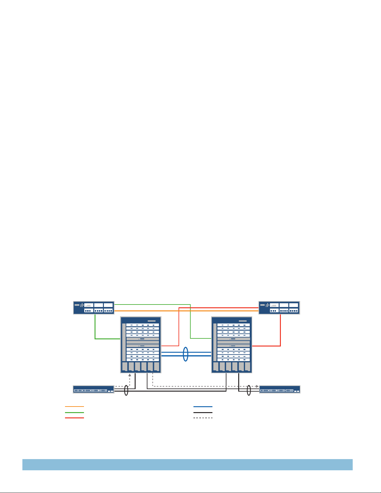
EX8200
Virtual Chassis
switch
2 x 10 Gigabit Ethernet LAG
Intra-XRE200 connection for HA (1GbE)
Active XRE200 to Internal RE connection (1GbE)
Standby XRE200 to Internal RE connection (1GbE)
Figure 1: EX8200 line of Ethernet Switches in a Virtual Chassis configuration
Stanby XRE200Active XRE200
EX8200
Virtual Chassis
switch
2 x 10 Gigabit Ethernet LAG
10GbE LAG intra-Virtual Chassis connection
10GbE links
Trac flow from access to access and access
to core/WAN
Page 3

XRE200
XRE200 External Routing Engine Specifications
Hardware
Interface Options
• 4 10/100/ 100BASE-T RJ-45 copper Virtual Chassis ports
(base model)
• 4 1000BASE-X GbE SFP fiber Virtual Chassis ports (optional)2
• 10/100/100BASE-T RJ-45 copper port for XRE-to-XRE or XRE-
to-Virtual Chassis connections
• Console port for management
Dimensions (W x H x D)
• 17.25 x 3.5 (2U) x 17.72 in (43.8 x 8.9 x 45 cm)
Rack Installation Kit
• Versatile two-post and four-post mounting options for 19-in.
server rack or datacom rack
LEDs
• System LEDs that indicate power, HDD activity, and hardware
alert status
• HD activity and fail LED on drive tray
Power
• 100 to 240 V, 50-60 Hz 250 W hot-swappable dual redundant
AC power supplies
• -38 to -72 V 560 W hot-swappable dual redundant DC power
supplies
Soware
Security
• RADIUS
• TACACS+
• Access control lists: Allow and deny
• SSH v1, v2
• Secure interface login and password
• Local proxy Address Resolution Protocol (ARP)
• Static ARP support
Layer 2 Features
• Jumbo frames (9216 bytes)
• 4096 VLANs
• 802.3ad—Link Aggregation Control Protocol (LACP)
• 802.1D—Spanning Tree Protocol (STP)
• 802.1w—Rapid Spanning Tree Protocol (RSTP)
• 802.1s—Multiple Spanning Tree Protocol (MSTP)
• VLAN Spanning Tree Protocol (VSTP)
• Redundant Trunk Group (RTG)
L3 Features
• Static routing
• RIP v1/v2
• OSPF v1/v2
• Filter-based forwarding
• Virtual Router Redundancy Protocol (VRRP)
• BGP (Advanced Feature license)
• IS-IS (Advanced Feature license)
• IPv6 (Advanced Feature license)2
• Bidirectional Forwarding Detection (BFD)
• Virtual routers
Link Aggregation
• 802.3ad support
- Number of link aggregation groups (LAGs) supported: 255
- Maximum number of ports per LAG: 12
• LAG load-sharing algorithm—bridged or routed (unicast or
multicast) traffic:
- IP: S/D IP
- TCP/UDP: S/D IP, S/D Port
- Non-IP: S/D MAC
- Tagged ports support in LAG
Quality of Service (QoS)
• Layer 2 QoS
• Layer 3 QoS
• Ingress policing: 1 rate 2 color
• Eight hardware queues per port
• Scheduling methods (egress): Strict priority (SP), shaped
deficit weighted round-robin (SDWRR)
• 802.1p, DiffServ code point (DSCP)/IP precedence trust and
marking
• Layers 2-4 classification criteria: Interface, MAC address,
Ethertype, 802.1p, VLAN, IP address, DSCP/IP precedence,
TCP/UDP port numbers, etc.
• Congestion avoidance capabilities: Tail drop eight queues
Multicast
• Internet Group Management Protocol (IGMP): v1, v2, v3
• IGMP snooping
• PIM-SM, PIM-DM, PIM-SSM
• Multicast Source Discovery Protocol (MSDP)
Troubleshooting
• Debugging: CLI via console, Telnet, or SSH
• Diagnostics: Show and debug command, statistics
• Traffic monitoring/mirroring (port, VLAN)
• IP tools: Extended ping and trace
• Junos OS commit and rollback
Trac Mirroring
• Port-based
• VLAN-based
• ACL-based mirroring
• Mirroring destination ports per system: 1
• LAG port monitoring
• Multiple destination ports monitored to 1 mirror (N:1)
• Maximum number of mirroring sessions: 1
• Mirroring to remote destination (over L2): 1 destination VLAN
2
Roadmap
3
Page 4

Safety and Compliance
Safety Certifications
• CSA 60950-1 (2003) Safety of Information Technology
Equipment
• UL 60950-1 (2003) Safety of Information Technology
Equipment
• EN 60950-1 (2001) Safety of Information Technology
Equipment
• IEC 60950-1 (2001) Safety of Information Technology
Equipment (with country deviations)
• EN 60825-1 +A1+A2 (1994) Safety of Laser Products—Part 1:
Equipment Classification
• EN 60825-2 (2000) Safety of Laser Products—Part 2: Safety of
Optical Fibre Communication Systems
Electromagnetic Compatibility Certifications
• FCC 47CFR Part 15 Class A
• EN 55022 Class A
• ICES-003 Class A
• VCCI Class A
• AS/NZS CISPR 22 Class A
• CISPR 22 Class A
• EN 55024
• EN 300386
• CE
Environmental
• Reduction of Hazardous Substances (ROHS) 5
Telco
• CLEI code
Environmental Ranges
• Operating temperature: 41° to 104°F (5° to 40°C)
• Storage temperature: -40° to 158°F (-40° to 70°C)
• Operating altitude: up to 10,000 ft (3,048 m)
• Non-operating altitude: up to 40,000 ft (12,192 m)
• Relative humidity operating: 8 to 90% (noncondensing)
• Relative humidity non-operating: 5 to 95% (noncondensing)
1
Available with Junos 10.4
2
Roadmap
Juniper Networks Services and Support
Juniper Networks is the leader in performance-enabling services
and support, which are designed to accelerate, extend, and
optimize your high-performance network. Our services allow
you to bring revenue-generating capabilities online faster so
you can realize bigger productivity gains and faster rollouts of
new business models and ventures. At the same time, Juniper
Networks ensures operational excellence by optimizing your
network to maintain required levels of performance, reliability, and
availability. For more details, please visit www.juniper.net/us/en/
products-services.
Ordering Information
BASE UNIT DESCRIPTION
EX-XRE200-AC EX8200 Virtual Chassis External Routing
EX-XRE200-DC EX8200 Virtual Chassis External Routing
Engine 200 with dual AC power supplies,
dual fans, two 160 GB hard disks and one
4-port 10/ 100/1000 BASE-T RJ-45 I/O
card
Engine 200 with dual DC power supplies,
dual fans, two 160 GB hard disks and one
4-port 10/ 100/1000 BASE-T RJ-45 I/O
card
Accessories and Spares
EX-XRE200-1GE-4F
EX-XRE200-1GE-4T XRE200 4-port 10/100/1000BASE-T
EX-XRE200-HDD160G 160 GB hard disk
EX-XRE200-FANTRAY Fan for XRE200
EX-XRE200-RMK-4POST Four-post rack mount kit
EX-XRE200-PWR-250-AC AC power supply (250 W)
EX-XRE200-PWR-560-DC DC power supply (560 W)
EX-XRE200-AFL Advanced Feature License
2
XRE200 4-port SFP I/O card
RJ-45 I/O card
About Juniper Networks
Juniper Networks is in the business of network innovation. From
devices to data centers, from consumers to cloud providers,
Juniper Networks delivers the software, silicon and systems that
transform the experience and economics of networking. The
company serves customers and partners worldwide. Additional
information can be found at www.juniper.net.
Corporate and Sales Headquarters
Juniper Networks, Inc.
1194 North Mathilda Avenue
Sunnyvale, CA 94089 USA
Phone: 888.JUNIPER (888.586.4737)
or 408.745.2000
Fax: 408.745.2100
www.juniper.net
Copyri ght 2010 Juniper Netw orks, Inc. All r ights reser ved. Juniper N etworks, t he Juniper Net works logo, Jun os,
NetScr een, and Screen OS are registere d trademarks o f Juniper Netw orks, Inc. in th e United States and oth er
countri es. All other trad emarks, se rvice marks , registered m arks, or regis tered serv ice marks are th e property o f
their re spective own ers. Junipe r Networks a ssumes no res ponsibilit y for any inaccurac ies in this docum ent. Juniper
Netwo rks reser ves the right to cha nge, modify, tran sfer, or otherw ise revise thi s publication w ithout notice.
1000352-001-EN Nov 2010
4
APAC Headquar ters
Juniper Networks (Hong Kong)
26/F, Citypla za One
1111 King’s Road
Taikoo Shing, Hong Kong
Phone: 852. 2332.3636
Fax: 852.2574.7803
Printed o n recycled pape r
EMEA Headquarters
Juniper Networks Ireland
Airside Business Park
Swords, County D ublin, Ireland
Phone: 35.31.8903.600
EMEA Sales: 00800.4586.4737
Fax: 35.31.8903.601
To purchase Juniper Networks solutions,
please contact your Juniper Networks
representative at 1-866-298-6428 or
authorized reseller.
 Loading...