

Page 1

WLA532 Access Point Hardware Documentation
Published: 2011-09-29
Revision
Copyright © 2011, Juniper Networks, Inc.
Page 2

Juniper Networks, Inc.
1194 North Mathilda Avenue
Sunnyvale, California 94089
USA
408-745-2000
www.juniper.net
This product includes the Envoy SNMPEngine, developed byEpilogue Technology, an IntegratedSystemsCompany.Copyright © 1986-1997,
Epilogue Technology Corporation. All rights reserved. This program and its documentation were developed at private expense, and no part
of them is in the public domain.
This product includes memory allocation software developed by Mark Moraes, copyright © 1988, 1989, 1993, University of Toronto.
This product includes FreeBSD software developed by the University of California, Berkeley, and its contributors. All of the documentation
and software included in the 4.4BSD and 4.4BSD-Lite Releases is copyrighted by the Regents of the University of California. Copyright ©
1979, 1980, 1983, 1986, 1988, 1989, 1991, 1992, 1993, 1994. The Regents of the University of California. All rights reserved.
GateD software copyright © 1995, the Regents of the University. All rights reserved. Gate Daemon was originated and developed through
release 3.0 by Cornell University and its collaborators. Gated is based on Kirton’s EGP, UC Berkeley’s routing daemon (routed), and DCN’s
HELLO routing protocol. Development of Gated has been supported in part by the National Science Foundation. Portions of the GateD
software copyright © 1988, Regents of the University of California. All rights reserved. Portions of the GateD software copyright © 1991, D.
L. S. Associates.
This product includes software developed by Maker Communications, Inc., copyright © 1996, 1997, Maker Communications, Inc.
Juniper Networks, Junos, Steel-Belted Radius, NetScreen, and ScreenOS are registered trademarks of Juniper Networks, Inc. in the United
States and other countries. The Juniper Networks Logo, the Junos logo, and JunosE are trademarks of Juniper Networks, Inc. All other
trademarks, service marks, registered trademarks, or registered service marks are the property of their respective owners.
Juniper Networks assumes no responsibility for any inaccuracies in this document. Juniper Networks reserves the right to change, modify,
transfer, or otherwise revise this publication without notice.
Products made or sold by Juniper Networks or components thereof might be covered by one or more of the following patents that are
owned by or licensed to Juniper Networks: U.S. Patent Nos. 5,473,599, 5,905,725, 5,909,440, 6,192,051, 6,333,650, 6,359,479, 6,406,312,
6,429,706, 6,459,579, 6,493,347, 6,538,518, 6,538,899, 6,552,918, 6,567,902, 6,578,186, and 6,590,785.
WLA 532 Access Point Hardware Documentation
Copyright © 2011, Juniper Networks, Inc.
All rights reserved.
Revision History
September 2011—Revision 1; initial release
The information in this document is current as of the date listed in the revision history.
END USER LICENSE AGREEMENT
The Juniper Networks product that is the subject of this technical documentation consists of (or is intended for use with) Juniper Networks
software. Use of such software is subject to the terms and conditions of the End User License Agreement (“EULA”) posted at
http://www.juniper.net/support/eula.html. By downloading, installing or using such software, you agree to the terms and conditions
of that EULA.
Copyright © 2011, Juniper Networks, Inc.ii
Page 3

Table of Contents
Part 1 Overview
Chapter 1 Access Point Overview . . . . . . . . . . . . . . . . . . . . . . . . . . . . . . . . . . . . . . . . . . . . . . 3
WLA532 AccessPoint Hardware Overview . . . . . . . . . . . . . . . . . . . . . . . . . . . . . . . . 3
MAC Address Information for WLA Series Access Points . . . . . . . . . . . . . . . . . . . . . 4
Chapter 2 Ports and Connectors . . . . . . . . . . . . . . . . . . . . . . . . . . . . . . . . . . . . . . . . . . . . . . . 7
Ethernet Connections for WLA532 Access Points . . . . . . . . . . . . . . . . . . . . . . . . . . 7
Status LEDs on WLA532 Access Point . . . . . . . . . . . . . . . . . . . . . . . . . . . . . . . . . . . 7
Part 2 Planning
Chapter 3 Planning Guidelines . . . . . . . . . . . . . . . . . . . . . . . . . . . . . . . . . . . . . . . . . . . . . . . . 13
Planning Guidelines for Using RingMaster to Plan a Mobility System . . . . . . . . . . 13
Standard PoE Information for WLA Series Access Points . . . . . . . . . . . . . . . . . . . . 14
Technical, Mechanical and Compliance Specifications for WLA Series Access
Points . . . . . . . . . . . . . . . . . . . . . . . . . . . . . . . . . . . . . . . . . . . . . . . . . . . . . . . . . 14
802.11 a/b/g/n Features . . . . . . . . . . . . . . . . . . . . . . . . . . . . . . . . . . . . . . . . . . . 14
Ceiling and Wall Mounting . . . . . . . . . . . . . . . . . . . . . . . . . . . . . . . . . . . . . . . . . 15
Mechanical and Compliance Specifications . . . . . . . . . . . . . . . . . . . . . . . . . . 15
Radio Specifications . . . . . . . . . . . . . . . . . . . . . . . . . . . . . . . . . . . . . . . . . . . . . 17
Chapter 4 Radio Requirements . . . . . . . . . . . . . . . . . . . . . . . . . . . . . . . . . . . . . . . . . . . . . . . 19
Radio Requirements for 2.4GHz . . . . . . . . . . . . . . . . . . . . . . . . . . . . . . . . . . . . . . . . 19
Radio Requirements for 5GHz . . . . . . . . . . . . . . . . . . . . . . . . . . . . . . . . . . . . . . . . . 19
Chapter 5 Certifications . . . . . . . . . . . . . . . . . . . . . . . . . . . . . . . . . . . . . . . . . . . . . . . . . . . . . 21
EMI/EMC Certifications for the WLA532 Access Point . . . . . . . . . . . . . . . . . . . . . . 21
Radio Safety Certifications for the WLA532 Access Point . . . . . . . . . . . . . . . . . . . 21
Part 3 Safety
Chapter 6 General Safety Information . . . . . . . . . . . . . . . . . . . . . . . . . . . . . . . . . . . . . . . . . 25
General Safety Standards and Agencies for the WLA532 Access Point . . . . . . . . 25
WLA532 Access Point Radio Frequency Exposure Guidelines . . . . . . . . . . . . . . . . 26
Chapter 7 General Guidelines . . . . . . . . . . . . . . . . . . . . . . . . . . . . . . . . . . . . . . . . . . . . . . . . 29
Part 4 Installation
Chapter 8 Installing the Access Point . . . . . . . . . . . . . . . . . . . . . . . . . . . . . . . . . . . . . . . . . 33
Installing the WLA532 Access Point on a Suspended Ceiling Rail . . . . . . . . . . . . . 33
Installing the WLA532 Access Point on a Wall . . . . . . . . . . . . . . . . . . . . . . . . . . . . 36
Connecting the Access Point to Wireless LAN Controllers . . . . . . . . . . . . . . . . . . . 39
iiiCopyright © 2011, Juniper Networks, Inc.
Page 4

WLA 532 Access Point Hardware Documentation
Chapter 9 Verification Tasks . . . . . . . . . . . . . . . . . . . . . . . . . . . . . . . . . . . . . . . . . . . . . . . . . . 41
Verifying the Health of WLA Series Access Points Using LEDs . . . . . . . . . . . . . . . . 41
Part 5 Troubleshooting
Chapter 10 Customer Support . . . . . . . . . . . . . . . . . . . . . . . . . . . . . . . . . . . . . . . . . . . . . . . . 45
Contacting Juniper for Missing WLA532 Access Point Parts . . . . . . . . . . . . . . . . . 45
Part 6 Index
Index . . . . . . . . . . . . . . . . . . . . . . . . . . . . . . . . . . . . . . . . . . . . . . . . . . . . . . . . . . . . . 49
Copyright © 2011, Juniper Networks, Inc.iv
Page 5

List of Figures
Part 1 Overview
Chapter 1 Access Point Overview . . . . . . . . . . . . . . . . . . . . . . . . . . . . . . . . . . . . . . . . . . . . . . 3
Figure 1: WLA532 Access Point . . . . . . . . . . . . . . . . . . . . . . . . . . . . . . . . . . . . . . . . . 3
Chapter 2 Ports and Connectors . . . . . . . . . . . . . . . . . . . . . . . . . . . . . . . . . . . . . . . . . . . . . . . 7
Figure 2: Status LED on WLA532 Access Point . . . . . . . . . . . . . . . . . . . . . . . . . . . . . 8
vCopyright © 2011, Juniper Networks, Inc.
Page 6

List of Tables
Part 1 Overview
Chapter 1 Access Point Overview . . . . . . . . . . . . . . . . . . . . . . . . . . . . . . . . . . . . . . . . . . . . . . 3
Table 1: MAC Address Information for WLA Series Access Points . . . . . . . . . . . . . . 4
Chapter 2 Ports and Connectors . . . . . . . . . . . . . . . . . . . . . . . . . . . . . . . . . . . . . . . . . . . . . . . 7
Table 2: Status LEDs on WLA532 Access Points . . . . . . . . . . . . . . . . . . . . . . . . . . . 8
Part 2 Planning
Chapter 3 Planning Guidelines . . . . . . . . . . . . . . . . . . . . . . . . . . . . . . . . . . . . . . . . . . . . . . . . 13
Table 3: Mechanical and Compliance Specification for WLA532 . . . . . . . . . . . . . . 15
Table 4: Radio Specification for WLA532 . . . . . . . . . . . . . . . . . . . . . . . . . . . . . . . . . 17
viiCopyright © 2011, Juniper Networks, Inc.
Page 7

PART 1
Overview
•
Access Point Overview on page 3
•
Ports and Connectors on page 7
1Copyright © 2011, Juniper Networks, Inc.
Page 8
CHAPTER 1
Access Point Overview
•
WLA532 AccessPoint Hardware Overview on page 3
•
MAC Address Information for WLA Series Access Points on page 4
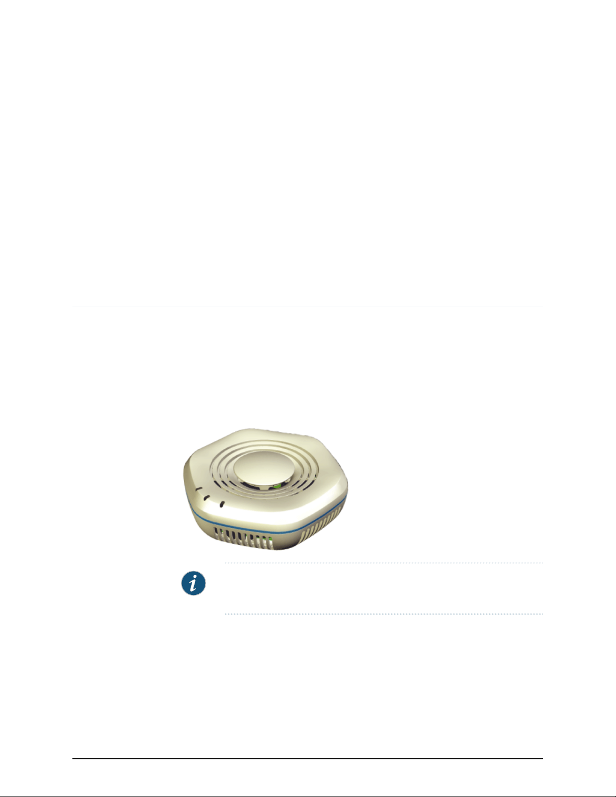
WLA532 AccessPoint Hardware Overview
Juniper Networks Enterprise wireless LAN Indoor Access Point, WLA532, is based on the
next evolution of 802.11n technology based radio chipsets. WLA 532 is a dual radio 3X3
multiple input, multiple output (MIMO) access point supporting up to three spatial
streams on each radio. WLA532 is a compact hexagonshaped access point and is targeted
at enterprise customers including verticals such as Healthcare, Education and other
carpeted offices.
Figure 1: WLA532 Access Point
NOTE: The WLA532 requires only hardware installation. All configurations
for the access point is done on the wireless LAN controllers.
The WLA532 access point supports:
•
In band spectrum monitoring and network spectrum mitigation
•
Minimum 450Mbps or 500 Mbps (? to be clarified during review) to wire from two
radios at large packets
•
One 2.4GHz 3x3 802.11n standard power radio subsystem
3Copyright © 2011, Juniper Networks, Inc.
Page 9

WLA 532 Access Point Hardware Documentation
•
One 5GHz 3x3 802.11n enhanced power radio subsystem
•
One Gigabit (10/100/1000 Base-T) Ethernet port
•
Power consumption within standard 802.3af power on GigE port
•
Spectrum Analysis
•
Hardware (DTLS) crypto acceleration for CAPWAP data path
•
3 spatial stream operation
•
Rate Adaptation features (3SS rates, 2SS rates and 1SS rates)
The WLA532 can be powered up and operational within 3 minutes and supports all
features of RingMaster and Mobility System Software (MSS).
The following wireless LAN controllers are supported by the WLA532 access point:
•
WLC2 Wireless LAN Controller
•
WLC8 Wireless LAN Controller
•
WLC800 Wireless LAN Controller
•
WLC880 Wireless LAN Controller
•
WLC2800 Wireless LAN Controller
Related
Documentation
General Safety Standards and Agencies for the WLA532 Access Point on page 25•
• Installing the WLA532 Access Point on a Suspended Ceiling Rail on page 33
• Installing the WLA532 Access Point on a Wall on page 36
MAC Address Information for WLA Series Access Points
The WLA series access points are assigned a unique block of 64 MAC addresses
(reviewers, please confirm?). Each radio has 32 MAC addresses and hence can support
up to 32 SSIDs, with one MAC address assigned to each SSID as a BSSID. The access
point MAC address block is listed on a label on the back of the access point. If the access
point is already deployed and running on the network, you can display the MAC address
assignments by using the show ap status command using the Mobility System Software
CLI. All MAC addresses for an access point are assigned based on the base MAC address
of the access point as described in Table.
Table 1: MAC Address Information for WLA Series Access Points
Access Point base MAC Address
Ethernet Port MAC Addresses
DescriptionMAC Address Type
The access point has a base MAC address. All the other addresses are assigned based
on this address
•
Ethernet port 1 equals the access point base MAC address
•
Ethernet port 2 equals the access point base MAC address + 1 (Not applicable for
WLA532 series).
Copyright © 2011, Juniper Networks, Inc.4
Page 10

Table 1: MAC Address Information for WLA Series Access Points (continued)
DescriptionMAC Address Type
•
5Ghz Radio and SSID MAC Addresses
2.4Ghz Radio and SSID MAC
Addresses
The 5Ghz radio equals the access point base MAC address + 1
•
The BSSIDs for the SSIDs configured on the 5Ghz radio end in odd numbers. The first
BSSID is equal to the access point’s base MAC address + 1. The next BSSID is equal
to the access point’s base MAC address + 3, and so on.
•
The 2.4Ghz radio equals the access point base MAC address
•
The BSSIDs for the SSIDs configured on the 2.4Ghz radio end in even numbers. The
first BSSID is equal to the access point base MAC address. The next BSSID is equal
to the access point base MAC address + 2, and so on.
Access Point Overview
Related
Documentation
• Radio Requirements for 2.4GHz on page 19
• Radio Requirements for 5GHz on page 19
5Copyright © 2011, Juniper Networks, Inc.
Page 11

CHAPTER 2
Ports and Connectors
•
Ethernet Connections for WLA532 Access Points on page 7
•
Status LEDs on WLA532 Access Point on page 7
Ethernet Connections for WLA532 Access Points
The WLA532 access point has one RJ-45 network port, which provides a 10/100/1000
autosensing (MDI/MDX) ethernet connection to a wireless LAN controller (WLC).
You can configure the connection between the access point and the controller either as
a direct connection or as an indirect connection through an intermediate layer 2 or layer
3 network. The WLA532 access point receives power and data through the RJ-45 port.
You use a Category 5 cable with straight-through signaling and standard RJ-45 connectors
to connect the access point to a controller or to a switch in the network. The access point
supports Power over Ethernet (IEEE 802.3af). It can also receive PoE power from Juniper
Networks wireless LAN controllers and Juniper Networks-approved power injectors.
NOTE: The access points do not support daisy-chain configurations. Do not
connect one access point to another access point.
Related
Documentation
Connecting the Access Point to Wireless LAN Controllers on page 39•
• Standard PoE Information for WLA Series Access Points on page 14
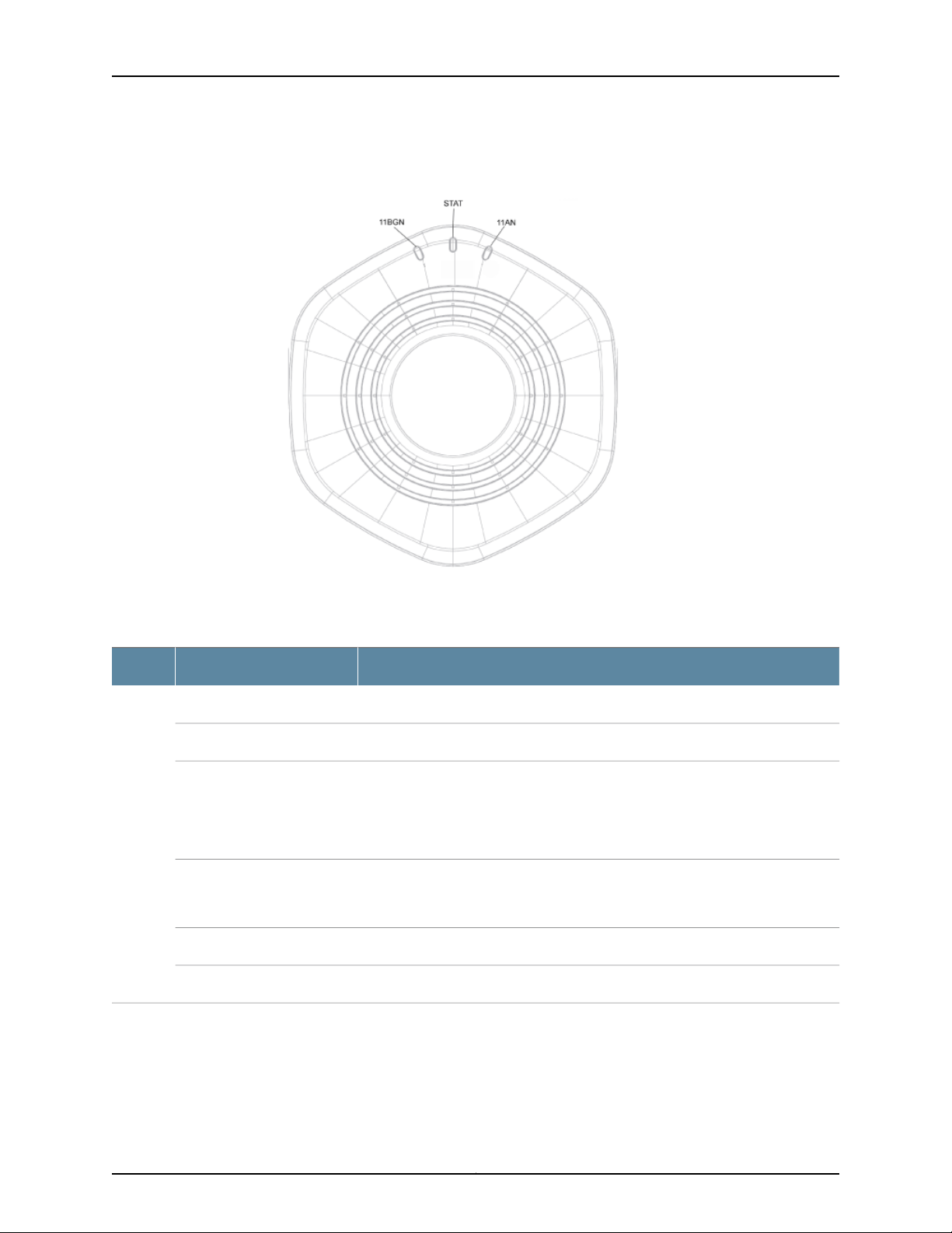
Status LEDs on WLA532 Access Point
The WLA532 access point has three status LEDs that indicatestatus information in green,
amber, and red colors.
7Copyright © 2011, Juniper Networks, Inc.
Page 12
WLA 532 Access Point Hardware Documentation
Figure 2: Status LED on WLA532 Access Point
Table 2 on page 8 describes the status LEDs and their states.
Table 2: Status LEDs on WLA532 Access Points
Status and DescriptionColorLabel
Off. The access point is powered off.UnlitLED in
the
center
Green, flashing
Green or amber, flashing
On. The access point is on power on sand is in self-test mode.Amber, flashing
On. The access point is waiting to receive boot instructions and a configuration file
from a wireless LAN controller.
Cindy, the products are named as WLC2, WLC8 etc. So, is it okay to just say WLC?
Or should we use wireless LAN controller always?)
On. The access point is booting and receiving a configuration file from the controller.
After the access point boots and receives a configuration file, the LED continues to
flash alternately green and amber until a radio is enabled.
On. The access point is powered on and is operational.Green
On. The access point has not been configured and is not operational.Red
Copyright © 2011, Juniper Networks, Inc.8
Page 13

Table 2: Status LEDs on WLA532 Access Points (continued)
Please clarify what is dedicated sensor
Status and DescriptionColorLabel
Off. The 5 GHz radio is disabled.LED on
the right
(11 AN)
the left
(11
BGN)
On. The 5 GHz radio is enabled.Green
On. Dedicated sensorAmber
On. The access point is transmitting and receiving on the 5 GHz radio.Green or amber, flashing
On. The radio has failed.Red
Off. The 2.4 GHz radio is disabled.LED on
On. The 2.4 GHz radio is enabled.Green
On. Dedicated sensorAmber
Ports and Connectors
Related
Documentation
On. The access point is transmitting and receiving on the 2.4GHz radio.Flash Green or Amber
On. The radio has failed.Red
• Ethernet Connections for WLA532 Access Points on page 7
• Radio Requirements for 2.4GHz on page 19
• Radio Requirements for 5GHz on page 19
9Copyright © 2011, Juniper Networks, Inc.
Page 14

PART 2
Planning
•
Planning Guidelines on page 13
•
Radio Requirements on page 19
•
Certifications on page 21
11Copyright © 2011, Juniper Networks, Inc.
Page 15

CHAPTER 3
Planning Guidelines
•
Planning Guidelines for Using RingMaster to Plan a Mobility System on page 13
•
Standard PoE Information for WLA Series Access Points on page 14
•
Technical, Mechanical and Compliance Specifications for WLA Series Access
Points on page 14
Planning Guidelines for Using RingMaster to Plan a Mobility System
The Juniper Networks Mobility System is an enterprise WLAN solution that seamlessly
integrates with an existing wired enterprise network. The Juniper Networks system provides
secure connectivity to both wireless and wired users in large environments such as office
buildings, hospitals, and university campuses. The Juniper Mobility System fulfills the
three fundamental requirements of an enterprise WLAN: it eliminates the distinction
betweenwired and wireless networks,allows users to work safelyfrom anywhere (secure
mobility), and provides a comprehensivesuite of intuitive tools for planning and managing
the network before and after deployment, greatly easing the operational burden on IT
resources.
Related
Documentation
If you are using RingMaster to plan your Mobility System installation, we recommend
that you create and verify a network plan for the entire installlation and generate an
wireless LAN access point (WLA) work order before installing the recommended WLAs.
A network plan and the WLA work order generatedfrom RingMaster provide the following
information about WLA installation and configuration:
•
Number of WLAs required for adequate wireless LAN (WLAN) capacity in each coverage
area.
•
Detailed installation-location for each WLA.
•
Settings for all WLAs in the WLAN.
Once your plan has been created and reviewed, you can arrange for the WLAN network
installation. System Administrators and anyone involved in the installation of the WLAN
System are responsible for the proper setup and operation in accordance to all rules and
regulations of the country in which the equipment operates.
Configuring the WLCs With RingMaster•
13Copyright © 2011, Juniper Networks, Inc.
Page 16

WLA 532 Access Point Hardware Documentation
Standard PoE Information for WLA Series Access Points
The WLA series access point operates as a powered device within standard IEEE 802.3af
Power over Ethernet (PoE) from either a mid or end span power source equipment. It
also operates on 802.3af+ (54V from power source equipement) or 802.3at (high power
POE), and WLA532 responds to 802.3at discoveryas an 802.3af class 3 device. The WLA
series access point POE circuitry operates at 85% or greater efficiency on a 40 V 350ma
14W input (dissipate less than 3.0W).
The WLA532 access point provides a PoE input circuit to the CPU to indicate if the
powered device input voltage is less than 42 V or not. This helps to identify poor quality
cable plants or power source equipment capability and allows the software to disable
some of the features.
Related
Ethernet Connections for WLA532 Access Points on page 7•
Documentation
Technical, Mechanical and Compliance Specifications for WLA Series Access Points
This section explains the technical, mechanical, and compliance specifications for WLA
series access points.
NOTE: For detailed compliance information see the Juniper Networks
Regulatory Guide located at: http://www.juniper.net/ and can be downloaded
in PDF format.
WARNING: In the U.S., locate the access point and any externally attached
antennas a minimum of 7.9 inches (20 centimeters) away from people. This
safety warning conforms with FCC radio frequency exposure limits for dipole
antennas such as those used in the access point.
802.11 a/b/g/n Features
The WLA532 access points supports:
•
High performance 11 Mbps (802.11b) or 54Mbps (802.11a/g) or 300Mbps(802.11n) data
rate
•
Wi-Fi, WPA certificated interoperability
•
WPA/WPA2 with PSK/802.1x with TKIP/AES
•
40-bit and 128-bit WEP
•
Seamless roaming within the IEEE 802.11 a/b/g/n WLAN infrastructure.
•
Adjustable output power support
•
Interoperability with Juniper Networks Wireless Security Switch
Copyright © 2011, Juniper Networks, Inc.14
Page 17

•
Single auto-sensing 10/100/1000 Ethernet port, configured as MDI
•
Comply with IEEE 802.3, 802.3u and 802.3ab standards
•
PowerDsine(Microsemi) GigE PoE injector support
•
802.3af PoE compatability
Ceiling and Wall Mounting
The WLA 532 access point can be mounted to a recessed 15/16” ceiling tile rail without
disrupting rail or tile alignment. The WLA532 access point hardware will be provided with
the following mounting adapters provided in an auxiliary mounting kit:
•
9/16” recessed ceiling tile rail adapter
•
Center tile mount adapter and wall mount adapter
•
Trapeze legacy mounting bracket adapter (Reviewers, is this required?)
•
North America single gang wall box adapter (minimum extension from wall, covers
wall box and cables)
Planning Guidelines
•
European Union single gang wall box adapter
Mechanical and Compliance Specifications
The mechanical and compliance specifications for WLA532 access point is listed in the
table
Table 3: Mechanical and Compliance Specification for WLA532
DescriptionSpecification
Size
Length: 14 centimeters (5.5 inches)
Width: 13.15 centimeters (5.1 inches)
Height: 5.3 centimeters (2 inches)
Without mounting bracket: 264 grams (9.31 ounces)Weight
0° C to 50° C (32° F to +122° F)Operating Temperature
-40° C to +70° C (-40° F to +158° F)Storage Temperature
5% to 95% non-condensingHumidity
? years ? (Reviewers, please confirmMTBF
Power over Ethernet (PoE)
Directive 2002/95/EC, 2006/122/EC China RoHS (?0RoHs/ IEEE
40 V to 54 V
IEEE 802.3af
15Copyright © 2011, Juniper Networks, Inc.
Page 18

WLA 532 Access Point Hardware Documentation
Table 3: Mechanical and Compliance Specification for WLA532 (continued)
DescriptionSpecification
Status indicators
Standards compliance
Safety and electromagnetic
compliance
Health/status and radio LEDs (For descriptions of the LEDs, see “Access Point LEDs in a
WLA 532” on page 7.
One RJ-45 port for 10/100/1000BASE-T Ethernet and Power over Ethernet (PoE)Wired network ports
IEEE 802.11
IEEE 802.11a
IEEE 802.11b
IEEE 802.11g
IEEE 802.3af
IEEE 802.11n
CAN/CSA-C22.2 No. 60950-1 Information Technology Equipment
UL 60950-1 (2nd Ed.) Information Technology Equipment
EN 60950-1 Information Technology Equipment
IEC 60950-1 Information Technology Equipment - Safety (All country deviations)
EN 60601-1-1 General Safety for medical electrical systems
Low Voltage Directive 2006/95/EEC
radio compliance
Encryption
IEEE 802.3at POE requirements
FCC CFR 47, Part 2 Frequency allocations and general treaty matters, General rules
FCC CFR 47, Part 15 Radio Frequency Devices - EN 300 328 EMC and Radio Spectrum
Matters 2.4GHz ISM band
EN 301 489-1 EMC and Radio Spectrum Matters: Common Technical requirements
EN 301 489-17 EMC and Radio Spectrum Matters: 2.4GHz wideband and 5GHz RLAN
EN 301 893 Broadband Radio Access Networks 5 GHz RLAN
RTTE Directive 1995/5/EC
Various Country Specific Radio Regulations
Wi-Fi Protected Access (WPA/WPA2)
Advanced Encryption Standard (AES)
40-bit/104-bit Wired-Equivalent Privacy (WEP)
Copyright © 2011, Juniper Networks, Inc.16
Page 19

Table 3: Mechanical and Compliance Specification for WLA532 (continued)
DescriptionSpecification
Planning Guidelines
General
Power-save mode supported
Transmit power control in 1 dBm increments
Supports up to 250 clients per radio
Supports Dynamic Frequency Selection
Radio Specifications
The mechanical and compliance specifications for WLA532 access point is listed in the
table.
Table 4: Radio Specification for WLA532
DescriptionSpecification
Antenna type
Antenna gain
Integrated diversity omnidirectional
Internal 3X3 Multiple Input Multiple Output(MIMO)
Internal: 2-3 dBi (2.4 GHz)
Internal: 4-5 dBi (5 GHz)
2.4 GHz to 5 GHz based on country regulationsFrequency band
Transmit power
Based on the country of operation specified by the system administratorOperating channels
802.11n rates: MCS 0 to MCS 23Association rates
Orthogonal frequency division multiplexing (OFDM)Modulation
18 dBm transmit power per chain (200mW combined 3-stream output power) and
-90dBm receive sensitivity at MCS0 data rate
12 dBm transmit power per chain (50mW combined 3-stream output power) and
-70dBm receive sensitivity at MCS23 data rate.
17Copyright © 2011, Juniper Networks, Inc.
Page 20

CHAPTER 4
Radio Requirements
•
Radio Requirements for 2.4GHz on page 19
•
Radio Requirements for 5GHz on page 19
Radio Requirements for 2.4GHz
The 2.4 GHz band mPCIe radio module is operational from channels 1 to 14 of legacy
802.11 bg or in 802.11 n 3x3 stream of 20 MHz channel modes. At MCS0 data rate, it
provides 18 dBm transmit power per chain (200 mW combined 3-stream output power)
and -90 dBm reception. With MCS23 data rate, it provides 12dBm transmit power per
chain (50 mW combined 3-stream output power) and -70 dBm reception. It consumes
less than 2.75 W at maximum power draw.
Reviewers, please clarify the performance details.
The 2.4 GHz horizontally polarized antenna model of WLA532 access point includes one
2.4GHz band, 2 dBi gain, omnidirectional, horizontally polarized internal antenna, which
maximizes the MIMO performance from 2dBi to -4dBi around the 360 degrees horizontal
plane.
The 2.4 GHz vertically polarized antenna model of WLA532 access point includes two
2.4 GHz band, 3 dBi gain, 5 degree down-tilt omnidirectional, vertically polarized internal
antenna, which maximizes the MIMO performance from 3dBi to -9dBi around the 360
degrees horizontal plane.
Related
Documentation
Radio Requirements for 5GHz on page 19•
Radio Requirements for 5GHz
The 5 GHz band mPCIe radio module is operational from channels 36 to 165 in legacy
802.11 a or 802.11 n 3x3 stream of 20 MHz and 40MHz channel modes. At MCS0 data
rate, it provides 18 dBm transmit power per chain (200 mW combined 3-stream output
power) and -90dBm reception. With MCS23 data rate, it provides 12dBm transmit power
per chain (50 mW combined 3-stream output power) and -67 dBm reception. It consumes
less than 4.25 W at maximum power draw.
Reviewers, please clarify the performance details.
19Copyright © 2011, Juniper Networks, Inc.
Page 21

WLA 532 Access Point Hardware Documentation
The 5 GHz horizontally polarized antenna model of WLA532 access point includes one
5 GHz band, 4 dBi gain, omnidirectional, horizontally polarized internal antenna, which
maximizes the MIMO performance from 4dBi to -6dBi around the 360 degrees horizontal
plane.
The 5 GHz vertically polarized antennas model of WLA532 access point includes two 5
GHz band, 5 dBi gain, 5 degree down-tilt omnidirectional, vertically polarized internal
antenna, which maximizes the MIMO performance from 5 dBi to -7 dBi around the 360
degrees horizontal plane.
Related
Documentation
• Radio Requirements for 2.4GHz on page 19
Copyright © 2011, Juniper Networks, Inc.20
Page 22

CHAPTER 5
Certifications
•
EMI/EMC Certifications for the WLA532 Access Point on page 21
•
Radio Safety Certifications for the WLA532 Access Point on page 21
EMI/EMC Certifications for the WLA532 Access Point
For a complete list of safety warnings and detailed compliance information, see the
Juniper Networks Regulatory Guide in the Wireless LAN Services (WLS) documentation
at http://www.juniper.net/techpubs/.
EMI/EMC Certification for Juniper WLA532 access point-specified standards and agencies:
•
FCC CFR 47, Part 2 Frequency allocations and general treaty matters, General rules
•
FCC CFR 47, Part 15 Radio Frequency Devices (Class B)
•
EN 55022 EMC Radiated Standard (Class B)
•
EN 55024 EMC Immunity Standard (Class B)
•
EN 300 386 EMC and Radio Spectrum Matters Telcom
•
EN 60601-1-2 EMC for medical electrical equipment
•
EMC Directive 2004/108/EC
Related
Radio Safety Certifications for the WLA532 Access Point on page 21•
Documentation
Radio Safety Certifications for the WLA532 Access Point
For a complete list of safety warnings and detailed compliance information, see the
Juniper Networks Regulatory Guide in the Wireless LAN Services (WLS) documentation
at http://www.juniper.net/techpubs/.
Radio certifications for Juniper WLA532 access point-specified standards and agencies:
•
FCC CFR 47, Part 2 Frequency allocations and general treaty matters, General rules
•
FCC CFR 47, Part 15 Radio Frequency Devices
•
EN 300 328 EMC and Radio Spectrum Matters 2.4GHz ISM band
21Copyright © 2011, Juniper Networks, Inc.
Page 23

WLA 532 Access Point Hardware Documentation
•
EN 301 489-1 EMC and Radio Spectrum Matters: Common Technical requirements
•
EN 301 489-17 EMC and Radio Spectrum Matters: 2.4GHz wideband and 5GHz RLAN
•
EN 301 893 Broadband Radio Access Networks 5 GHz RLAN
•
RTTE Directive 1995/5/EC
•
Various Country Specific Radio Regulations and World Markings.
Related
Documentation
• Safety Standards and Agencies
Copyright © 2011, Juniper Networks, Inc.22
Page 24

PART 3
Safety
•
General Safety Information on page 25
•
General Guidelines on page 29
23Copyright © 2011, Juniper Networks, Inc.
Page 25

CHAPTER 6
General Safety Information
•
General Safety Standards and Agencies for the WLA532 Access Point on page 25
•
WLA532 Access Point Radio Frequency Exposure Guidelines on page 26
General Safety Standards and Agencies for the WLA532 Access Point
For a complete list of safety warnings and detailed compliance information, see the
Juniper Networks Regulatory Guide in the Wireless LAN Services (WLS) documentation
at http://www.juniper.net/techpubs/.
The following certifications are required to comply with WLA532 access point specified
safety standards and agencies:
•
CAN/CSA-C22.2 No. 60950-1 Information Technology Equipment - Safety
•
UL 60950-1 (2nd Ed.) Information Technology Equipment - Safety
•
EN 60950-1 Information Technology Equipment - Safety (All country deviations)
Related
Documentation
•
EN 60601-1-1 General Safety for medical electrical systems
•
Low Voltage Directive 2006/95/EEC
•
IEEE 802.3at POE requirements
•
UL 2043 plenum-rated
•
RoHS - WLA532 product and manufacturing shall comply with EU RoHS 6 (Pb free),
EU WEEE, and China RoHS
Country specific certifications and World Markings for Juniper-specified standards and
agencies:
•
North America - WLA532-US
•
Israel - WLA532-IL
•
The remainder of the world - WLA532-WW
EMI/EMC Certifications for the WLA532 Access Point on page 21•
• Radio Safety Certifications for the WLA532 Access Point on page 21
25Copyright © 2011, Juniper Networks, Inc.
Page 26

WLA 532 Access Point Hardware Documentation
WLA532 Access Point Radio Frequency Exposure Guidelines
The following are Radio Frequency Exposure Guidelines for the WLA532 access point:
WLA Radio Safety Advisories:
Federal Communications Commission (FCC) Docket 96-8 for Spread Spectrum
Transmitters specifies a safety standard for human exposure to radio frequency
electromagnetic energy emitted by FCC-certified equipment. When used with the proper
antennas (shipped in the product), Juniper Networks MP access point products meet
the uncontrolled environmental limits found in OET-65 and ANSI C95.1-1991. Proper
installation of the access point according to the instructions in this manual will result in
user exposure that is below the FCC recommended limits.
Article 12- Without permission granted by the NCC, any company, enterprise, or user is
not allowed to change frequency, enhance transmitting power or alter original
characteristicas well as performance to an approved low powerradio-frequency devices.
Article 14- The low power radio-frequency devices shall not influence aircraft security
and interfere legal communications; If found, the user shall cease operating immediately
until no interference is achieved. The said legal communications means radio
communications is operated in compliance with the Telecommunications Act. The low
power radio-frequency devices must be susceptible with the interference from legal
communications or ISM radio wave radiated devices.
4.7.5- Within the 5.25-5.35 GHz band, U-NII devices will be restricted to indoor operations
to reduce any potential for harmful interference to co-channel MSS operations.
4.7.6- The operation of the U-NII devices is subject to the conditions that no harmful
interference is caused. The user must stop operating the device immediately should
Copyright © 2011, Juniper Networks, Inc.26
Page 27

General Safety Information
harmful interference is caused and shall not resume until the condition causing the
harmful interference has been corrected. Moreover, the interference must be accepted
that may be caused by the operation of an authorized communications, or ISM equipment
4.7.7- Manufacturers of U-NII devices are responsible for ensuring frequency stability
such that an emission is maintained within the band of operation under all conditions of
normal operation as specified in the user manual.
Translation: Class B (Broadcasting Communication Equipment for Home Use) As an
electromagnetic wave equipment for home use (Class B), this equipment is intended to
use mainly for home use and may be used in all areas.
Related
Documentation
• EMI/EMC Certifications for the WLA532 Access Point on page 21
• Safety Standards and Agencies
• Radio Safety Certifications for the WLA532 Access Point on page 21
27Copyright © 2011, Juniper Networks, Inc.
Page 28

CHAPTER 7
General Guidelines
29Copyright © 2011, Juniper Networks, Inc.
Page 29

PART 4
Installation
•
Installing the Access Point on page 33
•
Verification Tasks on page 41
31Copyright © 2011, Juniper Networks, Inc.
Page 30

CHAPTER 8
Installing the Access Point
•
Installing the WLA532 Access Point on a Suspended Ceiling Rail on page 33
•
Installing the WLA532 Access Point on a Wall on page 36
•
Connecting the Access Point to Wireless LAN Controllers on page 39
Installing the WLA532 Access Point on a Suspended Ceiling Rail
The WLA532 access point is an indoor, dual-band, dual-concurrent 3x3 IEEE 802.11n
enterprise WLAN access point with three data streams. You can install the WLA532
access point on the ceiling using the provided mounting bracket or on a junction box on
a wall. Mounting the device on the ceiling is the primary installation method, and
ceiling-mount installation steps are provided in this topic. You can purchase a junction
box wall-mount kit separately and follow the wall-mounting instructions in the Wireless
LAN Services (WLS) documentation at http://www.juniper.net/techpubs/ .
The WLA532 access point package includes a bracket for mounting the access point to
a recessed, 9/16-inch or 15/16-inch T ceiling-tile rail.
Ensure that you have the following parts and tools available to install the access point:
•
Ceiling-mount bracket (provided)
•
Category 5 cable, installed (not provided)
•
Mounting template (provided)
•
Box cutter or similar tool to cut ceiling tile (not provided)
•
(Optional) Security kit (separately orderable), which includes a security tool and a
security screw (not provided)
To install the access point on a suspended ceiling rail:
1. Select an installation location under a recessed rail in the ceiling.
2. Cut a hole as follows in the ceiling tile for the Category 5 cable:
a. Place the mounting template over the area where you plan to install the access
point.
b. Use the box cutter or similar tool to cut along the line marking the opening for the
port connectors.
33Copyright © 2011, Juniper Networks, Inc.
Page 31

WLA 532 Access Point Hardware Documentation
c. Remove the mounting template and the material you cut from the ceiling tile.
3. Run the Category 5 cable from the ceiling through the hole in the ceiling tile.
4. Ensure the snaps on the top of the ceiling-mount bracket are open so that the clips
can fully extend to fit around the ceiling rail. The bracket is shipped in an open position
so that it is ready to be clipped over a ceiling rail.
5. If the bracket is closed, open the snaps by pressing in and up with your thumbs on
both sides of the snaps on the bottom of the bracket until it is fully open.
6. With the bracket clips fully extended, align the clips with the rail and hook the clips
around the top sides of the rail. Push in on the sides of the bracket until the clips lock
over the rail. Listen for a clicking sound that indicates that the clips have locked. Be
sure the bracket has locked securely onto the rail by gently pulling down on the bracket
before installing the wireless LAN access point (WLA).
Copyright © 2011, Juniper Networks, Inc.34
Page 32

Installing the Access Point
7. Plug in the Category 5 cable that extends from the ceiling into the WLA.
8. Align the WLA with the bracket and press forward until the WLA clicks into place. Be
sure the WLA is seated correctly in the bracket by gently pulling down on the WLA.
9. If the WLA is not properly secured, press in on the release button on the top of the
bracket to unlock the WLA. Realign the access point, making sure the cable is still
connected, and push in until the WLA clicks securely into place.
35Copyright © 2011, Juniper Networks, Inc.
Page 33

WLA 532 Access Point Hardware Documentation
NOTE: We recommend that you use the optional security kit (separately
orderable) to secure the access point. The kit includes a special tool and
a security screw. Be sure that you retain the tool so that you can unlock
and move the access point. Never use a power tool to insert or remove
the security screw.
10. To lock the WLA into place, secure the security screw in through the release button
by using the tool provided with the security kit (do not overtighten the screw).
Related
Installing the WLA532 Access Point on a Wall on page 36•
Documentation
Installing the WLA532 Access Point on a Wall
The WLA532 access point is an indoor, dual-band, dual-concurrent 3x3 IEEE 802.11n
enterprise WLAN access point with three data streams. Mounting the device on the ceiling
Copyright © 2011, Juniper Networks, Inc.36
Page 34

Installing the Access Point
is the primary installation method, however, you can also install the WLA532 access
point on the wall using a specially ordered wall-mounting bracket. You can purchase a
wall-mount kit at http://www.juniper.net/techpubs/ .
The WLA532 access point wall-mount package includes a bracket for mounting the
access point to a wall socket.
Ensure that you have the following parts and tools available to install the access point:
•
Wall-mount bracket (provided)
•
Category 5 cable, installed (not provided)
•
two screws (provided)
•
standard flat-head screwdriver (not provided)
•
(Optional) Security kit (separately orderable), which includes a security tool and a
security screw (not provided)
To install the access point on the wall socket:
1. Hold the wall-mount centered over the wall socket and insert and secure the two
screws through the bracket into the wall using a standard flat-head screwdriver.
2. Plug in the Category 5 cable from the wall socket to the access point.
3. Align the access point with the wall bracket and push down until you hear the access
point click into place. Be sure the device is seated correctly in the wall bracket by
gently pulling up then down on the access point.
37Copyright © 2011, Juniper Networks, Inc.
Page 35

WLA 532 Access Point Hardware Documentation
4. If the access point is not properly secured, press the release button on the bottom of
the bracket to release the device. Realign the unit, making sure the cable is still
connected and push down until the access point clicks securely into place.
NOTE: We recommend that you use the optional security kit (separately
orderable) to secure the access point. The kit includes a special tool and
a security screw. Be sure that you retain the tool so that you can unlock
and move the access point. Never use a power tool to insert or remove
the security screw.
5. To lock the WLA into place, secure the security screw in through the release button
by using the tool provided with the security kit (do not overtighten the screw).
Copyright © 2011, Juniper Networks, Inc.38
Page 36

Installing the Access Point
Related
Installing the WLA532 Access Point on a Suspended Ceiling Rail on page 33•
Documentation
Connecting the Access Point to Wireless LAN Controllers
You can connect a wireless LAN access point to a Wireless LAN controller (WLC) directly
or indirectly through an intermediate layer 2 or layer 3 network.
To connect the access point directly to a WLC:
1. Insert one end of a Category 5 cable with a standard RJ-45 connector to the ethernet
port of the access point and the other end to ethernet port of the controller. For
connection to an access point, use a straight-through signaling cable.
2. Observe the access point LED for the port on the controller.
The link is activated if the LED is green and glowing steadily.
To configure the access point connection, use the RingMaster GUI or the Mobility System
Software CLI.
If you are installing the access point in a Wireless LAN mesh or wireless bridge
configuration, you must configure the access point connection before deploying the
accesspoint in the final location.For more information, see the Mobility SystemSoftware
Configuration Guide or the Configuration Guide.
Related
Documentation
• Mobility System Software Configuration Guide at
http://www.juniper.net/techpubs/en_US/release-independent/wireless/information-products/pathway-pages/wireless-lan/software-75.html.
39Copyright © 2011, Juniper Networks, Inc.
Page 37

WLA 532 Access Point Hardware Documentation
• WLA532 AccessPoint Hardware Overview on page 3
• Ethernet Connections for WLA532 Access Points on page 7
• Access Point LEDs in a WLA 532 on page 7
Copyright © 2011, Juniper Networks, Inc.40
Page 38

CHAPTER 9
Verification Tasks
•
Verifying the Health of WLA Series Access Points Using LEDs on page 41
Verifying the Health of WLA Series Access Points Using LEDs
After you install the WLA series access point and enable the PoE on the ethernet cable
connected to the access point, you can verify the access point status by observing the
health LED. The health or LINK LED indicates if the access point is operational or not.
•
If the LED is green and glowing steadily, the access point has booted successfully by
the wireless LAN controller and is operational.
•
If the LED is not steadily glowing green, contact the system administrator for the WLC.
Related
Documentation
• Access Point LEDs in a WLA 532 on page 7
41Copyright © 2011, Juniper Networks, Inc.
Page 39

PART 5
Troubleshooting
•
Customer Support on page 45
43Copyright © 2011, Juniper Networks, Inc.
Page 40

CHAPTER 10
Customer Support
•
Contacting Juniper for Missing WLA532 Access Point Parts on page 45
Contacting Juniper for Missing WLA532 Access Point Parts
If you receive your WLA532 access point installation kit with any incorrect, missing, or
damaged parts contact Juniper Networks at http://www.juniper.net. If possible, retain
the carton, including the original packing materials. Use them again to repack the product
if you need to return it. Refer to the following checklist to ensure you have received a
complete installation kit.
The WLA532 access point installation kit includes:
•
One WLA532 unit
•
One ceiling-mount bracket
•
Mounting template
•
WLA532 Access Point Quick Start Guide
Related
Documentation
NOTE: A junction box wall-mount kit can be ordered separately.
• Installing the WLA532 Access Point on a Suspended Ceiling Rail on page 33
• Installing the WLA532 Access Point on a Wall on page 36
45Copyright © 2011, Juniper Networks, Inc.
Page 41

PART 6
Index
•
Index on page 49
47Copyright © 2011, Juniper Networks, Inc.
Page 42

Index
49Copyright © 2011, Juniper Networks, Inc.
Page 43

WLA 532 Access Point Hardware Documentation
Copyright © 2011, Juniper Networks, Inc.50
 Loading...