

Page 1

TX Matrix Plus Router
Hardware Guide
Published: 2010-10-28
Copyright © 2010, Juniper Networks, Inc.
Page 2

Juniper Networks, Inc.
1194 North Mathilda Avenue
Sunnyvale, California 94089
USA
408-745-2000
www.juniper.net
This productincludes the Envoy SNMP Engine, developed by Epilogue Technology,an Integrated Systems Company. Copyright ©1986-1997,
Epilogue Technology Corporation. All rights reserved. This program and its documentation were developed at private expense, and no part
of them is in the public domain.
This product includes memory allocation software developed by Mark Moraes, copyright © 1988, 1989, 1993, University of Toronto.
This product includes FreeBSD software developed by the University of California, Berkeley, and its contributors. All of the documentation
and software included in the 4.4BSD and 4.4BSD-Lite Releases is copyrighted by the Regents of the University of California. Copyright ©
1979, 1980, 1983, 1986, 1988, 1989, 1991, 1992, 1993, 1994. The Regents of the University of California. All rights reserved.
GateD software copyright © 1995, the Regents of the University. All rights reserved. Gate Daemon was originated and developed through
release 3.0 by Cornell University and its collaborators. Gated is based on Kirton’s EGP, UC Berkeley’s routing daemon (routed), and DCN’s
HELLO routing protocol. Development of Gated has been supported in part by the National Science Foundation. Portions of the GateD
software copyright © 1988, Regents of the University of California. All rights reserved. Portions of the GateD software copyright © 1991, D.
L. S. Associates.
This product includes software developed by Maker Communications, Inc., copyright © 1996, 1997, Maker Communications, Inc.
Juniper Networks, the Juniper Networks logo, Junos, NetScreen, ScreenOS, and Steel-Belted Radius are registered trademarks of Juniper
Networks, Inc. in the United States and other countries. JunosE is a trademark of Juniper Networks, Inc. All other trademarks, service marks,
registered trademarks, or registered service marks are the property of their respective owners.
Juniper Networks assumes no responsibility for any inaccuracies in this document. Juniper Networks reserves the right to change, modify,
transfer, or otherwise revise this publication without notice.
Products made or sold by Juniper Networks or components thereof might be covered by one or more of the following patents that are
owned by or licensed to Juniper Networks: U.S. Patent Nos. 5,473,599, 5,905,725, 5,909,440, 6,192,051, 6,333,650, 6,359,479, 6,406,312,
6,429,706, 6,459,579, 6,493,347, 6,538,518, 6,538,899, 6,552,918, 6,567,902, 6,578,186, and 6,590,785.
TX Matrix Plus Router Hardware Guide
Copyright © 2009, Juniper Networks, Inc.
All rights reserved. Printed in USA.
Writing: Elizabeth Gardner
Editing: Fran Mues
Illustration: Faith Bradford Brown
Cover Design: Edmonds Design
Revision History
August 2010—Corporate rebranding.
January 2010—For Junos OS Release 10.1, added procedures for upgrading and integrating an operational T1600 router into the routing
matrix.
October 2009—Added that Junos OS Release 9.6R2 is the first supported release for the TX Matrix Plus and T1600 routers in a routing
matrix. For Junos OS Release 10.0, added support for nonstop activing routing.
August 2009—Initial release.
The information in this document is current as of the date listed in the revision history.
YEAR 2000 NOTICE
Juniper Networks hardware and software products are Year 2000 compliant. The Junos OS has no known time-related limitations through
the year 2038. However, the NTP application is known to have some difficulty in the year 2036.
Copyright © 2010, Juniper Networks, Inc.ii
Page 3

END USER LICENSE AGREEMENT
READ THIS END USER LICENSE AGREEMENT (“AGREEMENT”) BEFORE DOWNLOADING, INSTALLING, OR USING THE SOFTWARE.
BY DOWNLOADING, INSTALLING, OR USING THE SOFTWARE OR OTHERWISE EXPRESSING YOUR AGREEMENT TO THE TERMS
CONTAINED HEREIN, YOU (AS CUSTOMER OR IF YOU ARE NOT THE CUSTOMER, AS A REPRESENTATIVE/AGENT AUTHORIZED TO
BIND THE CUSTOMER) CONSENT TO BEBOUND BY THISAGREEMENT. IF YOUDO NOTOR CANNOT AGREE TO THE TERMS CONTAINED
HEREIN, THEN (A) DO NOT DOWNLOAD, INSTALL, OR USE THE SOFTWARE, AND (B) YOU MAY CONTACT JUNIPER NETWORKS
REGARDING LICENSE TERMS.
1. The Parties. The parties to this Agreement are (i) Juniper Networks, Inc. (if the Customer’s principal office is located in the Americas) or
Juniper Networks (Cayman) Limited(if the Customer’s principaloffice islocated outside theAmericas)(such applicable entitybeing referred
to herein as “Juniper”), and(ii) the person or organization that originallypurchased from Juniper or anauthorized Juniper reseller the applicable
license(s) for use of the Software (“Customer”) (collectively, the “Parties”).
2. The Software. In this Agreement, “Software” means the program modules and features of the Juniper or Juniper-supplied software, for
which Customer has paid the applicable license or support fees to Juniper or an authorized Juniper reseller, or which was embedded by
Juniper in equipment which Customer purchased from Juniper or an authorized Juniper reseller. “Software” also includes updates, upgrades
and new releases of such software. “Embedded Software” means Software which Juniper has embedded in or loaded onto the Juniper
equipment and any updates, upgrades, additions or replacements which are subsequently embedded in or loaded onto the equipment.
3. License Grant. Subject to payment ofthe applicablefees andthe limitations and restrictions set forth herein, Juniper grants to Customer
a non-exclusive and non-transferable license, without right to sublicense, to use the Software, in executable form only, subject to the
following use restrictions:
a. Customer shall use Embedded Software solely as embedded in, and for execution on, Juniper equipment originally purchased by
Customer from Juniper or an authorized Juniper reseller.
b. Customer shall use the Software on a single hardware chassis having a single processing unit, or as many chassis or processing units
for which Customer has paid the applicable license fees; provided, however, with respect to the Steel-Belted Radius or Odyssey Access
Client software only, Customer shall use such Software on a single computer containing a single physical random access memory space
and containing any number of processors. Use of the Steel-Belted Radius or IMS AAA software on multiple computers or virtual machines
(e.g., Solaris zones) requires multiple licenses, regardless of whether such computers or virtualizations are physically contained on a single
chassis.
c. Product purchase documents, paper or electronic user documentation, and/or the particular licenses purchased by Customer may
specify limitsto Customer’s useof the Software. Such limitsmay restrict use to a maximumnumber of seats,registered endpoints,concurrent
users, sessions, calls, connections, subscribers, clusters, nodes, realms, devices, links, ports or transactions, or require the purchase of
separate licenses to use particular features, functionalities, services, applications, operations, or capabilities, or provide throughput,
performance, configuration, bandwidth, interface, processing, temporal, or geographical limits. In addition, such limits may restrict the use
of the Software to managing certain kinds of networks or require the Software to be used only in conjunction with other specific Software.
Customer’s use of the Software shall be subject to all such limitations and purchase of all applicable licenses.
d. For any trial copy of the Software, Customer’s right to use the Software expires 30 days after download, installation or use of the
Software. Customer may operate the Software after the 30-day trial period only if Customer pays for a license to do so. Customer may not
extend or create an additional trial period by re-installing the Software after the 30-day trial period.
e. The Global Enterprise Edition of the Steel-Belted Radius software may be used by Customer only to manage access to Customer’s
enterprise network. Specifically, service provider customers are expressly prohibited from using the Global Enterprise Edition of the
Steel-Belted Radius software to support any commercial network access services.
The foregoing license is not transferable or assignable by Customer. No license is granted herein to any user who did not originally purchase
the applicable license(s) for the Software from Juniper or an authorized Juniper reseller.
4. Use Prohibitions. Notwithstanding the foregoing, the license provided herein does not permit the Customer to, and Customer agrees
not to and shall not: (a) modify, unbundle, reverse engineer, or create derivative works based on the Software; (b) make unauthorized
copies of the Software (except as necessary for backup purposes); (c) rent, sell, transfer, or grant any rights in and to any copy of the
Software,in any form, to any third party;(d) remove any proprietary notices, labels, or marks on or in anycopy ofthe Software or anyproduct
in which the Software is embedded; (e) distribute any copy of the Software to any third party, including as may be embedded in Juniper
equipment sold inthe secondhandmarket; (f) use any‘locked’or key-restricted feature, function, service, application,operation, or capability
without first purchasing the applicable license(s) and obtaining a valid key from Juniper, even if such feature, function, service, application,
operation, or capability is enabled without a key; (g) distribute any key for the Software provided by Juniper to any third party; (h) use the
iiiCopyright © 2010, Juniper Networks, Inc.
Page 4

Software in any manner that extends or is broader than the uses purchased by Customer from Juniper or an authorized Juniper reseller; (i)
use Embedded Software on non-Juniper equipment; (j) use Embedded Software (or make it available for use) on Juniper equipment that
the Customer did not originally purchase from Juniper or an authorized Juniper reseller; (k) disclose the results of testing or benchmarking
of the Software to any third party without the prior written consent of Juniper; or (l)use the Softwarein any manner other than as expressly
provided herein.
5. Audit. Customer shall maintain accurate records as necessary to verify compliance with this Agreement. Upon request by Juniper,
Customer shall furnish such records to Juniper and certify its compliance with this Agreement.
6. Confidentiality. The Parties agree that aspects of the Software and associated documentation are the confidential property of Juniper.
As such, Customer shall exercise all reasonable commercial efforts to maintain the Softwareand associated documentation in confidence,
which at a minimum includes restricting access to the Software to Customer employees and contractors having a need to use the Software
for Customer’s internal business purposes.
7. Ownership. Juniper and Juniper’s licensors, respectively, retain ownership of all right, title, and interest (including copyright) in and to
the Software, associated documentation, and all copies of the Software. Nothing in this Agreement constitutes a transfer or conveyance
of any right, title, or interest in the Software or associated documentation, or a sale of the Software, associated documentation, or copies
of the Software.
8. Warranty, Limitation of Liability, Disclaimer of Warranty. The warranty applicable to the Software shall be as set forth in the warranty
statementthat accompanies theSoftware (the “WarrantyStatement”). Nothingin thisAgreement shall giverise toany obligation to support
the Software. Support services may be purchased separately. Any such support shall be governed by a separate, written support services
agreement. TO THE MAXIMUM EXTENT PERMITTED BY LAW, JUNIPER SHALL NOT BE LIABLE FOR ANY LOST PROFITS, LOSS OF DATA,
OR COSTSOR PROCUREMENTOF SUBSTITUTE GOODS ORSERVICES, ORFOR ANY SPECIAL, INDIRECT,OR CONSEQUENTIAL DAMAGES
ARISING OUTOF THIS AGREEMENT,THE SOFTWARE, ORANY JUNIPEROR JUNIPER-SUPPLIED SOFTWARE. INNO EVENT SHALLJUNIPER
BE LIABLE FOR DAMAGES ARISING FROM UNAUTHORIZED OR IMPROPER USE OF ANY JUNIPER OR JUNIPER-SUPPLIED SOFTWARE.
EXCEPT AS EXPRESSLY PROVIDED IN THE WARRANTY STATEMENT TO THE EXTENT PERMITTED BY LAW, JUNIPER DISCLAIMS ANY
AND ALL WARRANTIES IN AND TO THE SOFTWARE (WHETHER EXPRESS, IMPLIED, STATUTORY, OR OTHERWISE), INCLUDING ANY
IMPLIED WARRANTY OF MERCHANTABILITY, FITNESS FOR A PARTICULAR PURPOSE, OR NONINFRINGEMENT. IN NO EVENT DOES
JUNIPER WARRANT THAT THE SOFTWARE, OR ANY EQUIPMENT OR NETWORK RUNNING THE SOFTWARE, WILL OPERATE WITHOUT
ERROR OR INTERRUPTION, OR WILL BE FREE OF VULNERABILITY TO INTRUSION OR ATTACK. In no event shall Juniper’s or its suppliers’
or licensors’ liability to Customer, whether in contract, tort (including negligence), breach of warranty, or otherwise, exceed the price paid
by Customer for the Software that gave rise to the claim, or if the Software is embedded in another Juniper product, the price paid by
Customer for such other product. Customer acknowledges and agrees that Juniper has set its prices and entered into this Agreement in
reliance upon the disclaimers of warranty and the limitations of liability set forth herein, that the same reflect an allocation of risk between
the Parties (including the risk that a contract remedy may fail of its essential purpose and cause consequential loss), and that the same
form an essential basis of the bargain between the Parties.
9. Termination. Any breach of this Agreement or failure by Customer to pay any applicable fees due shall result in automatic termination
of the license granted herein. Upon such termination, Customer shall destroy or return to Juniper all copies of the Software and related
documentation in Customer’s possession or control.
10. Taxes. All license fees payable under this agreement are exclusive of tax. Customer shall be responsible for paying Taxes arising from
the purchase of the license, or importation or use of the Software. If applicable, valid exemption documentation for each taxing jurisdiction
shall be provided to Juniper prior to invoicing, and Customer shall promptly notify Juniper if their exemption is revoked or modified. All
payments made by Customer shall be net of any applicable withholding tax. Customer will provide reasonable assistance to Juniper in
connection with such withholding taxes by promptly: providing Juniper with valid tax receipts and other required documentation showing
Customer’s payment of any withholding taxes; completing appropriate applications that would reduce the amount of withholding tax to
be paid; and notifying and assisting Juniper in any audit or tax proceeding related to transactions hereunder. Customer shall comply with
all applicable tax laws and regulations, and Customer will promptly pay or reimburse Juniper for all costs and damages related to any
liability incurred by Juniper as a result of Customer’s non-compliance or delay with its responsibilities herein. Customer’s obligations under
this Section shall survive termination or expiration of this Agreement.
11. Export. Customer agrees to comply with all applicable export laws and restrictions and regulations of any United States and any
applicable foreign agency or authority, and not to export or re-export the Software or any direct product thereof in violation of any such
restrictions, laws or regulations, or without all necessary approvals. Customer shall be liable for any such violations. The version of the
Software supplied to Customer may contain encryption or other capabilities restricting Customer’s ability to export the Software without
an export license.
Copyright © 2010, Juniper Networks, Inc.iv
Page 5

12. Commercial Computer Software. The Software is “commercial computer software” and is provided with restricted rights. Use,
duplication, or disclosure by the United States government is subject to restrictions set forth in this Agreement and as provided in DFARS
227.7201 through 227.7202-4, FAR 12.212, FAR 27.405(b)(2), FAR 52.227-19, or FAR 52.227-14(ALT III) as applicable.
13. Interface Information. To the extent required by applicable law, and at Customer's written request, Juniper shall provide Customer
with the interface information needed to achieve interoperability between the Software and another independently created program, on
payment of applicable fee, if any. Customer shall observe strict obligations of confidentiality with respect to such information and shall use
such information in compliance with any applicable terms and conditions upon which Juniper makes such information available.
14. Third Party Software. Any licensor of Juniper whose software is embedded in the Software and any supplier of Juniper whose products
or technology are embedded in (or services are accessed by) the Software shall be a third party beneficiary with respect to this Agreement,
and such licensor or vendor shall have the right toenforce this Agreement in its own name as if it were Juniper. In addition, certain third party
software may be provided with the Software and is subject to the accompanying license(s), if any, of its respective owner(s). To the extent
portions of the Software are distributed under and subject to open source licenses obligating Juniper to make the source code for such
portions publicly available (such as the GNU General Public License (“GPL”) or the GNU Library General Public License (“LGPL”)), Juniper
will make such source code portions (including Juniper modifications, as appropriate) available upon request for a period of up to three
years from the date of distribution. Such request can be made in writing to Juniper Networks, Inc., 1194 N. Mathilda Ave., Sunnyvale, CA
94089, ATTN: General Counsel. You may obtain a copy of the GPL at http://www.gnu.org/licenses/gpl.html, and a copy of the LGPL
at http://www.gnu.org/licenses/lgpl.html .
15. Miscellaneous. This Agreement shall be governed by the laws of the State of California without reference to its conflicts of laws
principles. The provisions of the U.N. Convention for the International Sale of Goods shall not apply to this Agreement. For any disputes
arising under this Agreement, the Parties hereby consent to the personal and exclusive jurisdiction of, and venue in, the state and federal
courts within Santa Clara County, California. This Agreement constitutes the entire and sole agreement between Juniper and the Customer
with respect to the Software, and supersedes all prior and contemporaneous agreements relating to the Software, whether oral or written
(including any inconsistent terms contained in a purchase order), except that the terms of a separate written agreement executed by an
authorized Juniper representative and Customer shall govern to the extent such terms are inconsistent or conflict with terms contained
herein. No modification to this Agreement nor any waiver of any rights hereunder shall be effective unless expressly assented to in writing
by the party to be charged. If any portion of this Agreement is held invalid, the Parties agree that such invalidity shall not affect the validity
of the remainder of this Agreement. This Agreement and associated documentation has been written in the English language, and the
Parties agree that the English version will govern. (For Canada: Les parties aux présentés confirment leur volonté que cette convention de
même que tous les documents y compris tout avis qui s'y rattaché, soient redigés en langue anglaise. (Translation: The parties confirm that
this Agreement and all related documentation is and will be in the English language)).
vCopyright © 2010, Juniper Networks, Inc.
Page 6

Copyright © 2010, Juniper Networks, Inc.vi
Page 7

Table of Contents
About the Documentation . . . . . . . . . . . . . . . . . . . . . . . . . . . . . . . . . . . . . . . . xxix
Junos OS Documentation and Release Notes . . . . . . . . . . . . . . . . . . . . . . . . . . . xxix
Objectives . . . . . . . . . . . . . . . . . . . . . . . . . . . . . . . . . . . . . . . . . . . . . . . . . . . . . . . . xxix
Audience . . . . . . . . . . . . . . . . . . . . . . . . . . . . . . . . . . . . . . . . . . . . . . . . . . . . . . . . . xxx
Documentation Conventions . . . . . . . . . . . . . . . . . . . . . . . . . . . . . . . . . . . . . . . . . xxx
Documentation Feedback . . . . . . . . . . . . . . . . . . . . . . . . . . . . . . . . . . . . . . . . . . . xxxi
Requesting Technical Support . . . . . . . . . . . . . . . . . . . . . . . . . . . . . . . . . . . . . . . xxxii
Self-Help Online Tools and Resources . . . . . . . . . . . . . . . . . . . . . . . . . . . . . xxxii
Opening a Case with JTAC . . . . . . . . . . . . . . . . . . . . . . . . . . . . . . . . . . . . . . xxxiii
Part 1 TX Matrix Plus Router Overview
Chapter 1 TX Matrix Plus Overview . . . . . . . . . . . . . . . . . . . . . . . . . . . . . . . . . . . . . . . . . . . . 3
TX Matrix Plus Router Description . . . . . . . . . . . . . . . . . . . . . . . . . . . . . . . . . . . . . . . 3
Chapter 2 TX Matrix Plus Hardware Component Overview . . . . . . . . . . . . . . . . . . . . . . . . 7
TX Matrix Plus Component Redundancy . . . . . . . . . . . . . . . . . . . . . . . . . . . . . . . . . . 7
TX Matrix Plus Switch-Fabric Chassis Description . . . . . . . . . . . . . . . . . . . . . . . . . . 8
TX Matrix Plus Midplane Description . . . . . . . . . . . . . . . . . . . . . . . . . . . . . . . . . . . . 11
TX Matrix Plus Switch Interface Boards Overview . . . . . . . . . . . . . . . . . . . . . . . . . . 13
TX Matrix Plus Switch Interface Boards Description . . . . . . . . . . . . . . . . . . . . 13
TX Matrix Plus TXP-F13 SIB Overview . . . . . . . . . . . . . . . . . . . . . . . . . . . . . . . 13
TXP-F13 SIB Description . . . . . . . . . . . . . . . . . . . . . . . . . . . . . . . . . . . . . . . 13
TXP-F13 SIB Slots . . . . . . . . . . . . . . . . . . . . . . . . . . . . . . . . . . . . . . . . . . . . 14
TX Matrix Plus TXP-F13 SIB LEDs . . . . . . . . . . . . . . . . . . . . . . . . . . . . . . . . . . . 15
TX Matrix Plus TXP-F2S SIB Overview . . . . . . . . . . . . . . . . . . . . . . . . . . . . . . . 17
TXP-F2S SIB Components . . . . . . . . . . . . . . . . . . . . . . . . . . . . . . . . . . . . . 17
TXP-F2S SIB Slots . . . . . . . . . . . . . . . . . . . . . . . . . . . . . . . . . . . . . . . . . . . 17
TX Matrix Plus TXP-F2S SIB LEDs . . . . . . . . . . . . . . . . . . . . . . . . . . . . . . . . . . 19
TX Matrix Plus Host Subsystem Overview . . . . . . . . . . . . . . . . . . . . . . . . . . . . . . . 20
TX Matrix Plus Host Subsystem Description . . . . . . . . . . . . . . . . . . . . . . . . . . 20
TX Matrix Plus Control Board Description . . . . . . . . . . . . . . . . . . . . . . . . . . . . 20
TX Matrix Plus TXP-CB Overview . . . . . . . . . . . . . . . . . . . . . . . . . . . . . . . . . . . 21
TXP-CB Description . . . . . . . . . . . . . . . . . . . . . . . . . . . . . . . . . . . . . . . . . . 21
Routing Engine Ports on the TXP-CB . . . . . . . . . . . . . . . . . . . . . . . . . . . . 23
TX Matrix Plus TXP-CB LEDs . . . . . . . . . . . . . . . . . . . . . . . . . . . . . . . . . . . . . . 23
TX Matrix Plus Routing Engine Description . . . . . . . . . . . . . . . . . . . . . . . . . . . 25
TX Matrix Plus RE-C2600 Routing Engine Overview . . . . . . . . . . . . . . . . . . . 26
RE-C2600 Description . . . . . . . . . . . . . . . . . . . . . . . . . . . . . . . . . . . . . . . 26
RE-C2600 Boot Sequence . . . . . . . . . . . . . . . . . . . . . . . . . . . . . . . . . . . . 28
TX Matrix Plus RE-C2600 LEDs . . . . . . . . . . . . . . . . . . . . . . . . . . . . . . . . . . . . 28
viiCopyright © 2010, Juniper Networks, Inc.
Page 8

TX Matrix Plus Router Hardware Guide
Chapter 3 Routing Matrix with a TX Matrix Plus Router System Architecture
TX Matrix Plus Craft Interface Overview . . . . . . . . . . . . . . . . . . . . . . . . . . . . . . . . . 30
Craft Interface Front Panel . . . . . . . . . . . . . . . . . . . . . . . . . . . . . . . . . . . . . . . . 30
LCD Modes . . . . . . . . . . . . . . . . . . . . . . . . . . . . . . . . . . . . . . . . . . . . . . . . . . . . . 31
LCD Display Idle Mode . . . . . . . . . . . . . . . . . . . . . . . . . . . . . . . . . . . . . . . . 31
LCD Display Alarm Mode . . . . . . . . . . . . . . . . . . . . . . . . . . . . . . . . . . . . . . 31
LCD Navigation Buttons . . . . . . . . . . . . . . . . . . . . . . . . . . . . . . . . . . . . . . . . . . 32
Alarm Cutoff/Lamp Test Button . . . . . . . . . . . . . . . . . . . . . . . . . . . . . . . . . . . . 32
TX Matrix Plus Craft Interface LED Overview . . . . . . . . . . . . . . . . . . . . . . . . . . . . . 32
Alarm LEDs on the TX Matrix Plus Craft Interface . . . . . . . . . . . . . . . . . . . . . . 33
Chassis Status LEDs on the TX Matrix Plus Craft Interface . . . . . . . . . . . . . . . 34
TXP-F13 SIB LEDs on the TX Matrix Plus Craft Interface . . . . . . . . . . . . . . . . . 34
Fan Tray LEDs on the TX Matrix Plus Craft Interface . . . . . . . . . . . . . . . . . . . . 35
Power Supply LEDs on the TX Matrix Plus Craft Interface . . . . . . . . . . . . . . . 35
TX Matrix Plus Connector Interface Panel Overview . . . . . . . . . . . . . . . . . . . . . . . 36
TX Matrix Plus Connector Interface Panel Description . . . . . . . . . . . . . . . . . . 36
TX Matrix Plus TXP-CIP Overview . . . . . . . . . . . . . . . . . . . . . . . . . . . . . . . . . . 36
TXP-CIP Components . . . . . . . . . . . . . . . . . . . . . . . . . . . . . . . . . . . . . . . . 36
TXP-CIP Ports . . . . . . . . . . . . . . . . . . . . . . . . . . . . . . . . . . . . . . . . . . . . . . 37
TXP-CIP Alarm Relay Contacts . . . . . . . . . . . . . . . . . . . . . . . . . . . . . . . . . 38
TX Matrix Plus TXP-CIP LEDs . . . . . . . . . . . . . . . . . . . . . . . . . . . . . . . . . . . . . 39
TX Matrix Plus Power System Overview . . . . . . . . . . . . . . . . . . . . . . . . . . . . . . . . . 41
TX Matrix Plus Power System Description . . . . . . . . . . . . . . . . . . . . . . . . . . . . 41
TX Matrix Plus Seven-Input 420-A Power Supplies Overview . . . . . . . . . . . . 41
Seven-Input 420-A Power Supplies Description . . . . . . . . . . . . . . . . . . . 41
Seven-Input 420-A Power Supply Load Sharing and Fault
Tolerance . . . . . . . . . . . . . . . . . . . . . . . . . . . . . . . . . . . . . . . . . . . . . . 42
TX Matrix Plus Seven-Input 420-A Power Supply LEDs . . . . . . . . . . . . . . . . . 43
TX Matrix Plus Cooling System Overview . . . . . . . . . . . . . . . . . . . . . . . . . . . . . . . . 45
Cooling System Description . . . . . . . . . . . . . . . . . . . . . . . . . . . . . . . . . . . . . . . 45
Fan Trays . . . . . . . . . . . . . . . . . . . . . . . . . . . . . . . . . . . . . . . . . . . . . . . . . . . . . . 46
Air Filters . . . . . . . . . . . . . . . . . . . . . . . . . . . . . . . . . . . . . . . . . . . . . . . . . . . . . . 47
TX Matrix Plus Cables Overview . . . . . . . . . . . . . . . . . . . . . . . . . . . . . . . . . . . . . . . 48
Fiber-Optic Array Cables . . . . . . . . . . . . . . . . . . . . . . . . . . . . . . . . . . . . . . . . . 48
Ethernet Management Cables . . . . . . . . . . . . . . . . . . . . . . . . . . . . . . . . . . . . . 48
Serial Cables . . . . . . . . . . . . . . . . . . . . . . . . . . . . . . . . . . . . . . . . . . . . . . . . . . . 48
TX Matrix Plus Rear Cable Management System . . . . . . . . . . . . . . . . . . . . . . . . . . 49
TX Matrix Plus Front Cable Manager . . . . . . . . . . . . . . . . . . . . . . . . . . . . . . . . . . . . 53
Overview . . . . . . . . . . . . . . . . . . . . . . . . . . . . . . . . . . . . . . . . . . . . . . . . . . . . . . . . . 55
Routing Matrix with a TX Matrix Plus Router System Architecture . . . . . . . . . . . . 55
Routing Matrix with a TX Matrix Plus Router System Control Plane
Architecture . . . . . . . . . . . . . . . . . . . . . . . . . . . . . . . . . . . . . . . . . . . . . . . . . . . . 56
Control Plane Connections from the TX Matrix Plus Router to the T1600
Routers . . . . . . . . . . . . . . . . . . . . . . . . . . . . . . . . . . . . . . . . . . . . . . . . . . . . . . . 58
Routing Matrix with a TX Matrix Plus Router Switch Fabric and Switching Plane
Architecture . . . . . . . . . . . . . . . . . . . . . . . . . . . . . . . . . . . . . . . . . . . . . . . . . . . 60
Copyright © 2010, Juniper Networks, Inc.viii
Page 9

Table of Contents
Switching Plane Connections from the TX Matrix Plus Router to the T1600
Routers . . . . . . . . . . . . . . . . . . . . . . . . . . . . . . . . . . . . . . . . . . . . . . . . . . . . . . . 63
Switching Plane Description . . . . . . . . . . . . . . . . . . . . . . . . . . . . . . . . . . . . . . . 63
Fiber-Optic Array Cable Connections Between TX Matrix Plus Routers and
T1600 Routers . . . . . . . . . . . . . . . . . . . . . . . . . . . . . . . . . . . . . . . . . . . . . . 63
Chapter 4 Junos OS in a Routing Matrix Overview . . . . . . . . . . . . . . . . . . . . . . . . . . . . . . . 71
Junos OS Releases in the Routing Matrix . . . . . . . . . . . . . . . . . . . . . . . . . . . . . . . . . 71
Junos OS Required . . . . . . . . . . . . . . . . . . . . . . . . . . . . . . . . . . . . . . . . . . . . . . . 71
Running Different Junos OS Releases on the Routing Engines . . . . . . . . . . . . . 71
TX Matrix Plus CLI Overview . . . . . . . . . . . . . . . . . . . . . . . . . . . . . . . . . . . . . . . . . . 72
TX Matrix Plus Junos OS Configuration Overview . . . . . . . . . . . . . . . . . . . . . . 72
Configuration Groups . . . . . . . . . . . . . . . . . . . . . . . . . . . . . . . . . . . . . . . . . . . . 73
TX Matrix Plus Junos Operational Overview . . . . . . . . . . . . . . . . . . . . . . . . . . 74
TX Matrix Plus Interface Names Overview . . . . . . . . . . . . . . . . . . . . . . . . . . . . . . . 75
SFC Interface . . . . . . . . . . . . . . . . . . . . . . . . . . . . . . . . . . . . . . . . . . . . . . . . . . . 75
LCC Interface . . . . . . . . . . . . . . . . . . . . . . . . . . . . . . . . . . . . . . . . . . . . . . . . . . . 77
Management Ethernet Interface . . . . . . . . . . . . . . . . . . . . . . . . . . . . . . . . . . . 79
FPC Interface . . . . . . . . . . . . . . . . . . . . . . . . . . . . . . . . . . . . . . . . . . . . . . . . . . . 79
Routing Engine Software Components . . . . . . . . . . . . . . . . . . . . . . . . . . . . . . . . . . 81
Routing Engine Software . . . . . . . . . . . . . . . . . . . . . . . . . . . . . . . . . . . . . . . . . . 81
Routing Protocol Process . . . . . . . . . . . . . . . . . . . . . . . . . . . . . . . . . . . . . . . . . 81
IPv4 Routing Protocols . . . . . . . . . . . . . . . . . . . . . . . . . . . . . . . . . . . . . . . 82
IPv6 Routing Protocols . . . . . . . . . . . . . . . . . . . . . . . . . . . . . . . . . . . . . . . 82
Routing and Forwarding Tables . . . . . . . . . . . . . . . . . . . . . . . . . . . . . . . . 83
Routing Policy . . . . . . . . . . . . . . . . . . . . . . . . . . . . . . . . . . . . . . . . . . . . . . 84
VPNs . . . . . . . . . . . . . . . . . . . . . . . . . . . . . . . . . . . . . . . . . . . . . . . . . . . . . . . . . 85
Interface Process . . . . . . . . . . . . . . . . . . . . . . . . . . . . . . . . . . . . . . . . . . . . . . . 85
Chassis Process . . . . . . . . . . . . . . . . . . . . . . . . . . . . . . . . . . . . . . . . . . . . . . . . 85
SNMP and MIB II Processes . . . . . . . . . . . . . . . . . . . . . . . . . . . . . . . . . . . . . . . 86
Management Process . . . . . . . . . . . . . . . . . . . . . . . . . . . . . . . . . . . . . . . . . . . . 86
Kernel Synchronization Process . . . . . . . . . . . . . . . . . . . . . . . . . . . . . . . . . . . . 86
Routing Engine Kernel . . . . . . . . . . . . . . . . . . . . . . . . . . . . . . . . . . . . . . . . . . . 86
Part 2 T1600 Router in a Routing Matrix Overview
Chapter 5 T1600 Router Overview . . . . . . . . . . . . . . . . . . . . . . . . . . . . . . . . . . . . . . . . . . . . 89
Hardware Requirements for a T1600 Router in a Routing Matrix with a TX Matrix
Plus Router . . . . . . . . . . . . . . . . . . . . . . . . . . . . . . . . . . . . . . . . . . . . . . . . . . . . 89
Chapter 6 T1600 Hardware Component Overview . . . . . . . . . . . . . . . . . . . . . . . . . . . . . . 93
TXP-T1600 SIBs . . . . . . . . . . . . . . . . . . . . . . . . . . . . . . . . . . . . . . . . . . . . . . . . . . . 93
RE-C1800 Routing Engines . . . . . . . . . . . . . . . . . . . . . . . . . . . . . . . . . . . . . . . . . . . 95
Routing Engine Functions . . . . . . . . . . . . . . . . . . . . . . . . . . . . . . . . . . . . . . . . . 95
T1600 Routing Engine Slots . . . . . . . . . . . . . . . . . . . . . . . . . . . . . . . . . . . . . . . 95
RE-C1800 Description . . . . . . . . . . . . . . . . . . . . . . . . . . . . . . . . . . . . . . . . . . . 95
LCC-CBs . . . . . . . . . . . . . . . . . . . . . . . . . . . . . . . . . . . . . . . . . . . . . . . . . . . . . . . . . . 96
ixCopyright © 2010, Juniper Networks, Inc.
Page 10

TX Matrix Plus Router Hardware Guide
Part 3 TX Matrix Plus Router Initial Installation
Chapter 7 TX Matrix Plus Router Installation Overview . . . . . . . . . . . . . . . . . . . . . . . . . 101
Chapter 8 Preparing for TX Matrix Plus Installation . . . . . . . . . . . . . . . . . . . . . . . . . . . . 103
Chapter 9 Unpacking the TX Matrix Plus Router . . . . . . . . . . . . . . . . . . . . . . . . . . . . . . . . 111
Chapter 10 Installing the TX Matrix Plus Mounting Hardware . . . . . . . . . . . . . . . . . . . . . 117
Chapter 11 Installing the TX Matrix Plus Router Using a Mechanical Lift . . . . . . . . . . . 127
Overview of Installing a TX Matrix Plus Router . . . . . . . . . . . . . . . . . . . . . . . . . . . 101
Overview of Preparing the Site for a TX Matrix Plus Router . . . . . . . . . . . . . . . . . 103
Routing Matrix with a TX Matrix Plus Router Hardware Configuration
Overview . . . . . . . . . . . . . . . . . . . . . . . . . . . . . . . . . . . . . . . . . . . . . . . . . . . . . 104
Routing Matrix Hardware Configurations . . . . . . . . . . . . . . . . . . . . . . . . . . . . 104
Centralized Configuration . . . . . . . . . . . . . . . . . . . . . . . . . . . . . . . . . . . . . . . . 104
Distributed Configuration . . . . . . . . . . . . . . . . . . . . . . . . . . . . . . . . . . . . . . . . 105
Rack Requirements for a TX Matrix Plus Router . . . . . . . . . . . . . . . . . . . . . . . . . . 106
Rack Size and Strength . . . . . . . . . . . . . . . . . . . . . . . . . . . . . . . . . . . . . . . . . . 106
Connection to Building Structure . . . . . . . . . . . . . . . . . . . . . . . . . . . . . . . . . . 107
Rack-Mounting Considerations . . . . . . . . . . . . . . . . . . . . . . . . . . . . . . . . . . . . 107
TX Matrix Plus Clearance Requirements for Airflow and Hardware
Maintenance . . . . . . . . . . . . . . . . . . . . . . . . . . . . . . . . . . . . . . . . . . . . . . . . . . 108
Fiber-Optic Array Cable Connections and Considerations . . . . . . . . . . . . . . . . . . 109
Unpacking the TX Matrix Plus Router Overview . . . . . . . . . . . . . . . . . . . . . . . . . . . 111
Tools and Parts Required to Unpack the TX Matrix Plus Router . . . . . . . . . . . . . . . 111
Unpacking the TX Matrix Plus Router . . . . . . . . . . . . . . . . . . . . . . . . . . . . . . . . . . . 112
Verifying TX Matrix Plus Router Parts Received . . . . . . . . . . . . . . . . . . . . . . . . . . . 113
Overview of Installing TX Matrix Plus Mounting Hardware . . . . . . . . . . . . . . . . . . 117
Installing the TX Matrix Plus Mounting Hardware for a Four-Post Rack . . . . . . . . 117
Installing Cage Nuts, If Needed . . . . . . . . . . . . . . . . . . . . . . . . . . . . . . . . . . . . 117
Installing the Four-Post Mounting Shelf and Rear Support Bracket . . . . . . . 119
Removing the Center-Mounting Brackets . . . . . . . . . . . . . . . . . . . . . . . . . . . 120
Installing the TX Matrix Plus Mounting Hardware for an Open-Frame Rack . . . . 122
Assembling the Open-Frame Rack Mounting Shelf . . . . . . . . . . . . . . . . . . . . 122
Installing Cage Nuts, If Needed . . . . . . . . . . . . . . . . . . . . . . . . . . . . . . . . . . . . 122
Installing the Open-Frame Rack Mounting Shelf . . . . . . . . . . . . . . . . . . . . . . 124
Overview of Installing a TX Matrix Plus Router with a Mechanical Lift . . . . . . . . . 127
Tools Required to Install the TX Matrix Router Using a Lift . . . . . . . . . . . . . . . . . . 128
Removing TX Matrix Plus Components Before Installing the Chassis . . . . . . . . . 128
Removing the Seven-Input 420–A DC Power Supply Input Power Trays . . . 128
Removing the Seven-Input 420-A DC Power Supplies . . . . . . . . . . . . . . . . . 130
Removing the Rear Fan Trays . . . . . . . . . . . . . . . . . . . . . . . . . . . . . . . . . . . . . . 131
Removing the TXP-F13 SIBs . . . . . . . . . . . . . . . . . . . . . . . . . . . . . . . . . . . . . . 132
Removing the Front Fan Trays . . . . . . . . . . . . . . . . . . . . . . . . . . . . . . . . . . . . . 133
Removing the TXP-CBs and Routing Engines . . . . . . . . . . . . . . . . . . . . . . . . 135
Copyright © 2010, Juniper Networks, Inc.x
Page 11

Table of Contents
Removing the TXP-F2S SIBs . . . . . . . . . . . . . . . . . . . . . . . . . . . . . . . . . . . . . . 137
Installing the TX Matrix Plus Router Using a Lift . . . . . . . . . . . . . . . . . . . . . . . . . . 138
Reinstalling TX Matrix Plus Components After Installing the Chassis . . . . . . . . . 144
Reinstalling the Rear Fan Trays . . . . . . . . . . . . . . . . . . . . . . . . . . . . . . . . . . . . 144
Reinstalling the Power Supplies . . . . . . . . . . . . . . . . . . . . . . . . . . . . . . . . . . . 145
Reinstalling the TXP-F13 SIBs . . . . . . . . . . . . . . . . . . . . . . . . . . . . . . . . . . . . . 147
Reinstalling the Front Fan Trays . . . . . . . . . . . . . . . . . . . . . . . . . . . . . . . . . . . 148
Reinstalling the Host Subsystems . . . . . . . . . . . . . . . . . . . . . . . . . . . . . . . . . 149
Reinstalling the TXP-F2S SIBs . . . . . . . . . . . . . . . . . . . . . . . . . . . . . . . . . . . . 150
Installing the TX Matrix Plus Rear Cable Management System . . . . . . . . . . . . . . 151
Identify the Parts of the Rear Cable Management System . . . . . . . . . . . . . . 151
Installing the Rear Cable Management System Comb Assembly . . . . . . . . . 152
Installing the Rear Cable Management System Shelves . . . . . . . . . . . . . . . . 153
Installing the Rear Cable Management System Arms . . . . . . . . . . . . . . . . . . 154
Installing the TX Matrix Plus Front Cable Manager . . . . . . . . . . . . . . . . . . . . . . . . 155
Chapter 12 Connecting the TX Matrix Plus Router to External Devices . . . . . . . . . . . . . 157
Tools and Parts Required for Connecting the TX Matrix Plus Router to External
Devices . . . . . . . . . . . . . . . . . . . . . . . . . . . . . . . . . . . . . . . . . . . . . . . . . . . . . . . 157
Connecting the TX Matrix Plus Router to a Network Device . . . . . . . . . . . . . . . . . 158
Connecting the TX Matrix Plus Router to a Management Console or Auxiliary
Device . . . . . . . . . . . . . . . . . . . . . . . . . . . . . . . . . . . . . . . . . . . . . . . . . . . . . . . 160
Connecting the TX Matrix Plus Router to External Alarm-Reporting Devices . . . 162
Chapter 13 Grounding and Providing Power to the TX Matrix Plus Router . . . . . . . . . . 165
Overview of Installing TX Matrix Plus Grounding and Power . . . . . . . . . . . . . . . . 165
Tools and Parts Required for Connecting the TX Matrix Plus Router to Ground
and Power . . . . . . . . . . . . . . . . . . . . . . . . . . . . . . . . . . . . . . . . . . . . . . . . . . . . 166
Grounding the TX Matrix Plus Router . . . . . . . . . . . . . . . . . . . . . . . . . . . . . . . . . . 166
Providing Power to a Seven-Input 420-A Power Supply . . . . . . . . . . . . . . . . . . . . 167
Connecting Power to a Seven-Input 420-A Power Supply . . . . . . . . . . . . . . 167
Powering On the TX Matrix Plus Router . . . . . . . . . . . . . . . . . . . . . . . . . . . . . . 171
Powering Off the TX Matrix Plus Router . . . . . . . . . . . . . . . . . . . . . . . . . . . . . . . . . 173
Chapter 14 Configuring the TX Matrix Plus Router . . . . . . . . . . . . . . . . . . . . . . . . . . . . . . . 175
Preparing to Configure the TX Matrix Plus Router . . . . . . . . . . . . . . . . . . . . . . . . . 175
Performing the Initial Software Configuration for the TX Matrix Plus Router . . . . 175
Entering Configuration Mode . . . . . . . . . . . . . . . . . . . . . . . . . . . . . . . . . . . . . . 176
Configuring User Accounts and Passwords . . . . . . . . . . . . . . . . . . . . . . . . . . 176
Configuring System Attributes . . . . . . . . . . . . . . . . . . . . . . . . . . . . . . . . . . . . . 177
Committing the Configuration . . . . . . . . . . . . . . . . . . . . . . . . . . . . . . . . . . . . . 178
Configuring Specific LCC Chassis Features for T1600 Routers . . . . . . . . . . . . . . . 179
Configuring a T1600 Router to Be Offline . . . . . . . . . . . . . . . . . . . . . . . . . . . . . . . 179
Configuring the TX Matrix PlusRouter to Generate anAlarm ifthe T1600Routers
in the Routing Matrix Do Not Come Online . . . . . . . . . . . . . . . . . . . . . . . . . . 180
xiCopyright © 2010, Juniper Networks, Inc.
Page 12

TX Matrix Plus Router Hardware Guide
Chapter 15 Connecting the Fiber-Optic Array Cables to the TX Matrix Plus Router . . . 181
Part 4 Integrating T1600 Routers into the Routing Matrix
Chapter 16 Upgrading and Integrating an Operational T1600 Router . . . . . . . . . . . . . . 199
Chapter 17 Upgrading an Offline T1600 Router Before Integrating It into a Routing
Tools and Parts Required for Connecting the Fiber-Optic Array Cables to the TX
Matrix Plus Router . . . . . . . . . . . . . . . . . . . . . . . . . . . . . . . . . . . . . . . . . . . . . . 181
Connecting the Fiber-Optic Array Cables to the TX Matrix Plus Router . . . . . . . . 181
Labeling the Fiber-Optic Array Cables . . . . . . . . . . . . . . . . . . . . . . . . . . . . . . 182
Connecting the Fiber-Optic Array Cables to the TX Matrix Plus Router . . . . 189
Overview of Preparing to Upgrade and Integrate an Operational T1600
Router . . . . . . . . . . . . . . . . . . . . . . . . . . . . . . . . . . . . . . . . . . . . . . . . . . . . . . . 199
Overview of Upgrading and Integrating an Operational T1600 Router . . . . . . . . 201
Tools and Parts Required for Upgrading and Integrating an Operational T1600
Router . . . . . . . . . . . . . . . . . . . . . . . . . . . . . . . . . . . . . . . . . . . . . . . . . . . . . . . 202
Upgrading the T1600 Host Subsystems in an Operational T1600 Router . . . . . 203
Preparing the T1600 Router for Graceful Switchover . . . . . . . . . . . . . . . . . . 203
Upgrading the Host Subsystems in an Operational T1600 Router . . . . . . . 204
Upgrading the Junos OS on an Operational T1600 Router and TX Matrix Plus
Router . . . . . . . . . . . . . . . . . . . . . . . . . . . . . . . . . . . . . . . . . . . . . . . . . . . . . . . 206
Upgrading the T1600 Power Supplies in an Operational T1600 Router . . . . . . . 207
Upgrading the Rear Fan Tray in an Operational T1600 Router . . . . . . . . . . . . . . . 207
Installing the T1600 Rear Cable Management System . . . . . . . . . . . . . . . . . . . . 208
Creating a Configuration File for the Integration of an Operational T1600
Router . . . . . . . . . . . . . . . . . . . . . . . . . . . . . . . . . . . . . . . . . . . . . . . . . . . . . . . 210
Upgrading and Connecting the Switching Planes in an Operational T1600
Router . . . . . . . . . . . . . . . . . . . . . . . . . . . . . . . . . . . . . . . . . . . . . . . . . . . . . . . . 211
Preparing to Upgrade the SIBs in an Operational T1600 Router . . . . . . . . . . 212
Upgrading a SIB in an Operational T1600 Router . . . . . . . . . . . . . . . . . . . . . 213
Connecting a Switching Plane in an Operational T1600 Router . . . . . . . . . . 214
Deleting the Upgrade Mode Statement . . . . . . . . . . . . . . . . . . . . . . . . . . . . . 219
Connecting the Control Planes in an Operational T1600 Router . . . . . . . . . . . . . 219
Setting the M/S Configuration Switches on the T1600 LCC-CBs . . . . . . . . . . . . . 221
Transferring the T1600 Router Configuration to the TX Matrix Plus Router in an
Operational T1600 Router . . . . . . . . . . . . . . . . . . . . . . . . . . . . . . . . . . . . . . . . 221
Transferring Control of the T1600 Router to the TX Matrix Plus Router . . . . . . . 222
Matrix . . . . . . . . . . . . . . . . . . . . . . . . . . . . . . . . . . . . . . . . . . . . . . . . . . . . . . . . . . 223
Overview of Upgrading an Offline T1600 Router Before Integrating it into a
Routing Matrix . . . . . . . . . . . . . . . . . . . . . . . . . . . . . . . . . . . . . . . . . . . . . . . . . 223
Tools and Parts Required to Upgrade the T1600 Router Hardware
Components . . . . . . . . . . . . . . . . . . . . . . . . . . . . . . . . . . . . . . . . . . . . . . . . . . 225
Upgrading an Offline T1600 Router Before Integrating it into a Routing
Matrix . . . . . . . . . . . . . . . . . . . . . . . . . . . . . . . . . . . . . . . . . . . . . . . . . . . . . . . . 225
Upgrading the Routing Engines in the T1600 Router . . . . . . . . . . . . . . . . . . 225
Upgrading the Junos OS on a T1600 Router . . . . . . . . . . . . . . . . . . . . . . . . . 225
Powering Off the T1600 Router . . . . . . . . . . . . . . . . . . . . . . . . . . . . . . . . . . . 226
Replacing the T1600 Power Supplies . . . . . . . . . . . . . . . . . . . . . . . . . . . . . . 226
Copyright © 2010, Juniper Networks, Inc.xii
Page 13

Table of Contents
Upgrading the T1600 Rear Fan Tray . . . . . . . . . . . . . . . . . . . . . . . . . . . . . . . . 227
Setting the Chassis ID on the T1600 Router . . . . . . . . . . . . . . . . . . . . . . . . . 227
Upgrading the T-CBs in the T1600 Router with LCC-CBs . . . . . . . . . . . . . . . 227
Upgrading the SIBs in the T1600 Router . . . . . . . . . . . . . . . . . . . . . . . . . . . . 228
Registering Your T1600 Upgrade . . . . . . . . . . . . . . . . . . . . . . . . . . . . . . . . . . . . . . 229
Chapter 18 Integrating an Offline T1600 Router into a Routing Matrix . . . . . . . . . . . . . 231
Overview of Integrating an Offline T1600 Router into a Routing Matrix . . . . . . . . 231
Tools and Parts Required to Integrate an Offline T1600 Router . . . . . . . . . . . . . . 232
Connecting an Offline T1600 Router to the TX Matrix Plus Router . . . . . . . . . . . 232
Connecting the Control Planes . . . . . . . . . . . . . . . . . . . . . . . . . . . . . . . . . . . . 232
Connecting the Fiber-Optic Array Cables to the TXP-T1600 SIBs . . . . . . . . 234
Powering On the T1600 Router . . . . . . . . . . . . . . . . . . . . . . . . . . . . . . . . . . . . . . . 242
Displaying the Assigned MAC Addresses for the PIC Interfaces in the Routing
Matrix . . . . . . . . . . . . . . . . . . . . . . . . . . . . . . . . . . . . . . . . . . . . . . . . . . . . . . . . 242
Creatinga Configuration File on the T1600 Router forIntegrationinto theRouting
Matrix . . . . . . . . . . . . . . . . . . . . . . . . . . . . . . . . . . . . . . . . . . . . . . . . . . . . . . . . 243
Transferring the T1600 Router Configuration to the TX Matrix Plus Router . . . . 244
Chapter 19 Verifying the State of the TX Matrix Plus and T1600 Router . . . . . . . . . . . 245
Overview of Verifying the State of a Routing Matrix . . . . . . . . . . . . . . . . . . . . . . . 245
Verifying the State of the Routing Matrix Control Plane . . . . . . . . . . . . . . . . . . . . 246
Verifying That the FPCs on the T1600 Router Are Detected and Online . . . . . . . 247
Verifying the State of the Interfaces on a T1600 Router . . . . . . . . . . . . . . . . . . . 250
Verifying the State of the Switching Planes in the Routing Matrix . . . . . . . . . . . . 251
Verifying the State of the Links in the Routing Matrix . . . . . . . . . . . . . . . . . . . . . . 258
Part 5 TX Matrix Plus Hardware Maintenance, Troubleshooting, and
Replacement Procedures
Chapter 20 Maintaining TX Matrix Plus Hardware Components . . . . . . . . . . . . . . . . . . 265
Tools and Parts Required for Maintaining TX Matrix Plus Components . . . . . . . 265
Routine Maintenance Procedures for the TX Matrix Plus Router . . . . . . . . . . . . . 266
Maintaining TX Matrix Plus Cooling System Components . . . . . . . . . . . . . . . . . . 266
Maintaining the Air Filters . . . . . . . . . . . . . . . . . . . . . . . . . . . . . . . . . . . . . . . . 266
Maintaining the Fan Trays . . . . . . . . . . . . . . . . . . . . . . . . . . . . . . . . . . . . . . . . 267
Maintaining the TX Matrix Plus Routing Engines . . . . . . . . . . . . . . . . . . . . . . . . . 268
Maintaining the TX Matrix Plus TXP-CBs . . . . . . . . . . . . . . . . . . . . . . . . . . . . . . . 268
Maintaining the TX Matrix Plus Power Supplies . . . . . . . . . . . . . . . . . . . . . . . . . . 268
Maintaining the TX Matrix Plus SIBs . . . . . . . . . . . . . . . . . . . . . . . . . . . . . . . . . . . 269
Verifying the Status of the TXP-F13 SIBs . . . . . . . . . . . . . . . . . . . . . . . . . . . . 269
Verifying the Status of the TXP-F2S SIBs . . . . . . . . . . . . . . . . . . . . . . . . . . . 270
Maintaining Fiber-Optic Array Components in the Routing Matrix . . . . . . . . . . . 270
Verifying the Status of the Switch Fabric Links . . . . . . . . . . . . . . . . . . . . . . . 270
Cleaning Fiber-Optic Array Components with the Dry Cloth Cleaning
Tool . . . . . . . . . . . . . . . . . . . . . . . . . . . . . . . . . . . . . . . . . . . . . . . . . . . . . . 271
xiiiCopyright © 2010, Juniper Networks, Inc.
Page 14

TX Matrix Plus Router Hardware Guide
Chapter 21 Troubleshooting TX Matrix Plus Hardware Components . . . . . . . . . . . . . . 275
Chapter 22 Replacing TX Matrix Plus Hardware Components . . . . . . . . . . . . . . . . . . . . 323
TX Matrix Plus Troubleshooting Resources . . . . . . . . . . . . . . . . . . . . . . . . . . . . . . 276
TX Matrix Plus LED Overview . . . . . . . . . . . . . . . . . . . . . . . . . . . . . . . . . . . . . . . . . 276
Craft Interface LED Overview . . . . . . . . . . . . . . . . . . . . . . . . . . . . . . . . . . . . . 276
Component LED Overview . . . . . . . . . . . . . . . . . . . . . . . . . . . . . . . . . . . . . . . 277
TX Matrix Plus Alarm Messages Overview . . . . . . . . . . . . . . . . . . . . . . . . . . . . . . . 277
TX Matrix Plus Chassis Alarm Messages Description . . . . . . . . . . . . . . . . . . 278
T1600 Router Chassis Alarm Messages . . . . . . . . . . . . . . . . . . . . . . . . . . . . . 278
SONET/SDH Interface Alarm Messages . . . . . . . . . . . . . . . . . . . . . . . . . . . . 278
Troubleshooting TX Matrix Plus Alarms . . . . . . . . . . . . . . . . . . . . . . . . . . . . . . . . 279
Deactivating Alarms on the TX Matrix Plus Craft Interface . . . . . . . . . . . . . . 279
Displaying TX Matrix Plus SFC and LCC Alarm Messages Information . . . . 280
Troubleshooting T1600 Router Chassis Alarm Messages . . . . . . . . . . . . . . . . . . . 281
Troubleshooting the TX Matrix Plus Craft Interface . . . . . . . . . . . . . . . . . . . . . . . 282
Troubleshooting the TX Matrix Plus Cooling System . . . . . . . . . . . . . . . . . . . . . . 283
Troubleshooting the TX Matrix Plus Power System . . . . . . . . . . . . . . . . . . . . . . . 290
Troubleshooting the TX Matrix Plus SIBs . . . . . . . . . . . . . . . . . . . . . . . . . . . . . . . 294
Troubleshooting the Switching Planes in the Routing Matrix . . . . . . . . . . . . . . . 305
Troubleshooting the TX Matrix Plus TXP-CIPs . . . . . . . . . . . . . . . . . . . . . . . . . . . 309
Troubleshooting the TX Matrix Plus Host Subsystem . . . . . . . . . . . . . . . . . . . . . . 311
Troubleshooting the TX Matrix Plus TXP-CBs . . . . . . . . . . . . . . . . . . . . . . . . . . . . 311
Troubleshooting the TX Matrix Plus Routing Engines . . . . . . . . . . . . . . . . . . . . . . 312
Troubleshooting the Logical Disconnection ofa T1600 Router from the TX Matrix
Plus Router . . . . . . . . . . . . . . . . . . . . . . . . . . . . . . . . . . . . . . . . . . . . . . . . . . . . 314
Testing a Fiber-Optic Array Port . . . . . . . . . . . . . . . . . . . . . . . . . . . . . . . . . . . . . . . 315
Testing a Fiber-Optic Array Cable . . . . . . . . . . . . . . . . . . . . . . . . . . . . . . . . . . . . . 316
Rolling Back the Integration on the T1600 Router . . . . . . . . . . . . . . . . . . . . . . . . 318
Preparing to Roll Back the Integration . . . . . . . . . . . . . . . . . . . . . . . . . . . . . . 318
Removing the Control Plane Connections . . . . . . . . . . . . . . . . . . . . . . . . . . . 319
Removing the Switching Planes . . . . . . . . . . . . . . . . . . . . . . . . . . . . . . . . . . . 319
Returning to the Original T1600 Configuration . . . . . . . . . . . . . . . . . . . . . . . 320
TX Matrix Plus Field-Replaceable Units (FRUs) . . . . . . . . . . . . . . . . . . . . . . . . . . 323
Understanding the Effect of Taking the Host Subsystem Offline . . . . . . . . . . . . 324
Understanding the Effect of Switching to a TX Matrix Plus or T1600 Backup
Routing Engine . . . . . . . . . . . . . . . . . . . . . . . . . . . . . . . . . . . . . . . . . . . . . . . . 325
Tools and Parts Required to Replace TX Matrix Plus Hardware Components . . 326
Replacing a TX Matrix Plus TXP-CIP . . . . . . . . . . . . . . . . . . . . . . . . . . . . . . . . . . . 327
Removing a TXP-CIP . . . . . . . . . . . . . . . . . . . . . . . . . . . . . . . . . . . . . . . . . . . 328
Installing a TXP-CIP . . . . . . . . . . . . . . . . . . . . . . . . . . . . . . . . . . . . . . . . . . . . 329
Replacing TX Matrix Plus Cables . . . . . . . . . . . . . . . . . . . . . . . . . . . . . . . . . . . . . . 330
Replacing Routing Matrix Control Plane Cables . . . . . . . . . . . . . . . . . . . . . . . 331
Removing a Control Plane Cable . . . . . . . . . . . . . . . . . . . . . . . . . . . . . . . 331
Connecting a Control Plane Cable . . . . . . . . . . . . . . . . . . . . . . . . . . . . . 332
Replacing a Management Ethernet Cable . . . . . . . . . . . . . . . . . . . . . . . . . . . 332
Removing the Managment Ethernet Cable . . . . . . . . . . . . . . . . . . . . . . 333
Installing the Management Ethernet Cable . . . . . . . . . . . . . . . . . . . . . . 333
Copyright © 2010, Juniper Networks, Inc.xiv
Page 15

Table of Contents
Replacing a Console or Auxiliary Cable . . . . . . . . . . . . . . . . . . . . . . . . . . . . . 334
Removing a Console or Auxiliary Cable . . . . . . . . . . . . . . . . . . . . . . . . . . 335
Installing a Console or Auxiliary Cable . . . . . . . . . . . . . . . . . . . . . . . . . . 335
Replacing a Fiber-Optic Array Cable . . . . . . . . . . . . . . . . . . . . . . . . . . . . . . . 336
Removing a Fiber-Optic Array Cable . . . . . . . . . . . . . . . . . . . . . . . . . . . . 337
Installing a Fiber-Optic Array Cable . . . . . . . . . . . . . . . . . . . . . . . . . . . . 338
Replacing TX Matrix Plus Cooling System Components . . . . . . . . . . . . . . . . . . . . 341
Replacing a TX Matrix Plus Front Fan Tray . . . . . . . . . . . . . . . . . . . . . . . . . . . 341
Removing a TX Matrix Plus Front Fan Tray . . . . . . . . . . . . . . . . . . . . . . . 341
Installing a TX Matrix Plus Front Fan Tray . . . . . . . . . . . . . . . . . . . . . . . . 342
Replacing a TX Matrix Plus Rear Fan Tray . . . . . . . . . . . . . . . . . . . . . . . . . . . 344
Removing a TX Matrix Plus Rear Fan Tray . . . . . . . . . . . . . . . . . . . . . . . 344
Installing a TX Matrix Plus Rear Fan Tray . . . . . . . . . . . . . . . . . . . . . . . . 345
Replacing a TX Matrix Plus Lower Front Air Filter . . . . . . . . . . . . . . . . . . . . . 346
Removing a TX Matrix Plus Lower Front Air Filter . . . . . . . . . . . . . . . . . . 347
Installing a TX Matrix Plus Lower Front Air Filter . . . . . . . . . . . . . . . . . . 348
Replacing a TX Matrix Plus Left Front Air Filter . . . . . . . . . . . . . . . . . . . . . . . 349
Removing a TX Matrix Plus Left Front Air Filter . . . . . . . . . . . . . . . . . . . 350
Installing a TX Matrix Plus Front Left Air Filter . . . . . . . . . . . . . . . . . . . . 351
Replacing the TX Matrix Plus Craft Interface . . . . . . . . . . . . . . . . . . . . . . . . . . . . 352
Removing the Craft Interface . . . . . . . . . . . . . . . . . . . . . . . . . . . . . . . . . . . . . 353
Installing the Craft Interface . . . . . . . . . . . . . . . . . . . . . . . . . . . . . . . . . . . . . . 353
Replacing TX Matrix Plus Host Subsystem Components . . . . . . . . . . . . . . . . . . 354
Taking the Host Subsystem Offline . . . . . . . . . . . . . . . . . . . . . . . . . . . . . . . . 354
Replacing a TXP-CB . . . . . . . . . . . . . . . . . . . . . . . . . . . . . . . . . . . . . . . . . . . . 357
Removing a TXP-CB . . . . . . . . . . . . . . . . . . . . . . . . . . . . . . . . . . . . . . . . 357
Installing a TXP-CB . . . . . . . . . . . . . . . . . . . . . . . . . . . . . . . . . . . . . . . . . 359
Replacing a Routing Engine . . . . . . . . . . . . . . . . . . . . . . . . . . . . . . . . . . . . . . 360
Removing a Routing Engine . . . . . . . . . . . . . . . . . . . . . . . . . . . . . . . . . . . 361
Installing a Routing Engine . . . . . . . . . . . . . . . . . . . . . . . . . . . . . . . . . . . 362
Replacing TX Matrix Plus SIBs . . . . . . . . . . . . . . . . . . . . . . . . . . . . . . . . . . . . . . . . 363
Taking a Switching Data Plane Offline . . . . . . . . . . . . . . . . . . . . . . . . . . . . . 364
Replacing a TXP-F13 SIB . . . . . . . . . . . . . . . . . . . . . . . . . . . . . . . . . . . . . . . . 366
Removing a TXP-F13 SIB . . . . . . . . . . . . . . . . . . . . . . . . . . . . . . . . . . . . . 366
Installing a TXP-F13 SIB . . . . . . . . . . . . . . . . . . . . . . . . . . . . . . . . . . . . . 368
Replacing a TXP-F2S SIB . . . . . . . . . . . . . . . . . . . . . . . . . . . . . . . . . . . . . . . . 370
Removing a TXP-F2S SIB . . . . . . . . . . . . . . . . . . . . . . . . . . . . . . . . . . . . 370
Installing a TXP-F2S SIB . . . . . . . . . . . . . . . . . . . . . . . . . . . . . . . . . . . . . 372
Replacing TX Matrix Plus Power System Components . . . . . . . . . . . . . . . . . . . . 373
Replacing a TX Matrix Plus Seven-Input 420-A Power Supply . . . . . . . . . . . 373
Removing a Seven-Input 420-A Power Supply . . . . . . . . . . . . . . . . . . . 373
Installing a Seven-Input 420-A Power Supply . . . . . . . . . . . . . . . . . . . . 375
Powering On a Seven-Input 420-A Power Supply . . . . . . . . . . . . . . . . . 376
Replacing a TX Matrix Plus Seven-Input 430-A Power Supply Input Power
Tray . . . . . . . . . . . . . . . . . . . . . . . . . . . . . . . . . . . . . . . . . . . . . . . . . . . . . . 377
Removing an Input Power Tray . . . . . . . . . . . . . . . . . . . . . . . . . . . . . . . . 378
Disconnecting the DC Power Cables from an Input Power Tray . . . . . . 378
Connecting the DC Power Cables to the Replacement Input Power
Tray . . . . . . . . . . . . . . . . . . . . . . . . . . . . . . . . . . . . . . . . . . . . . . . . . . 379
xvCopyright © 2010, Juniper Networks, Inc.
Page 16

TX Matrix Plus Router Hardware Guide
Part 6 Appendixes
Appendix A TX Matrix Plus Safety and Regulatory Compliance Information . . . . . . . . 389
Installing an Input Power Tray . . . . . . . . . . . . . . . . . . . . . . . . . . . . . . . . 380
Connecting a Seven-Input 420-A Power Supply . . . . . . . . . . . . . . . . . . 380
Replacing a DC Power Supply Cable . . . . . . . . . . . . . . . . . . . . . . . . . . . . . . . 382
Removing a DC Power Supply Cable . . . . . . . . . . . . . . . . . . . . . . . . . . . 382
Installing a DC Power Supply Cable . . . . . . . . . . . . . . . . . . . . . . . . . . . . 383
Definition of Safety Warning Levels . . . . . . . . . . . . . . . . . . . . . . . . . . . . . . . . . . . 389
TX Matrix Plus General Safety Guidelines and Warnings . . . . . . . . . . . . . . . . . . . 391
General Safety Guidelines for M Series, MX Series, and T Series Routers . . . 391
TX Matrix Plus Preventing Electrostatic Discharge Damage . . . . . . . . . . . . . 392
General Safety Warnings for M Series, MX Series, and T Series Routers . . . 395
Qualified Personnel Warning . . . . . . . . . . . . . . . . . . . . . . . . . . . . . . . . . 395
Restricted Access Area Warning . . . . . . . . . . . . . . . . . . . . . . . . . . . . . . . 396
Fire Safety Requirements for M Series, MX Series, and T Series Routers . . . . . . . 397
General Fire Safety Requirements . . . . . . . . . . . . . . . . . . . . . . . . . . . . . . . . . 397
Fire Suppression . . . . . . . . . . . . . . . . . . . . . . . . . . . . . . . . . . . . . . . . . . . . . . . 398
Fire Suppression Equipment . . . . . . . . . . . . . . . . . . . . . . . . . . . . . . . . . . . . . 398
TX Matrix Plus Installation Safety Guidelines and Warnings . . . . . . . . . . . . . . . . 398
TX Matrix Plus Installation Safety Guidelines . . . . . . . . . . . . . . . . . . . . . . . . 399
General Installation Safety Guidelines . . . . . . . . . . . . . . . . . . . . . . . . . . 399
Chassis Lifting Guidelines . . . . . . . . . . . . . . . . . . . . . . . . . . . . . . . . . . . . 399
Installation Safety Warnings for M Series, MX Series, and T Series
Routers . . . . . . . . . . . . . . . . . . . . . . . . . . . . . . . . . . . . . . . . . . . . . . . . . . . 399
Installation Instructions Warning . . . . . . . . . . . . . . . . . . . . . . . . . . . . . . 400
Rack-Mounting Requirements and Warnings . . . . . . . . . . . . . . . . . . . . 400
Ramp Warning . . . . . . . . . . . . . . . . . . . . . . . . . . . . . . . . . . . . . . . . . . . . 404
TX Matrix Plus Laser and LED Guidelines and Warnings . . . . . . . . . . . . . . . . . . . 404
TX Matrix Plus Laser and LED Safety Guidelines . . . . . . . . . . . . . . . . . . . . . 404
General Laser Safety Guidelines . . . . . . . . . . . . . . . . . . . . . . . . . . . . . . 404
TX Matrix Plus Laser Safety Standards . . . . . . . . . . . . . . . . . . . . . . . . . 405
TX Matrix Plus Laser and LED Safety Warnings . . . . . . . . . . . . . . . . . . . . . . 405
Class 1M Laser Product Warning . . . . . . . . . . . . . . . . . . . . . . . . . . . . . . . 405
Class 1 LED Product Warning . . . . . . . . . . . . . . . . . . . . . . . . . . . . . . . . . 406
Laser Beam Warning . . . . . . . . . . . . . . . . . . . . . . . . . . . . . . . . . . . . . . . . 406
Radiation from Open Port Apertures Warning . . . . . . . . . . . . . . . . . . . . 407
Unterminated Fiber-Optic Array Cable Warning . . . . . . . . . . . . . . . . . . 408
Maintenance and Operational Safety Warnings for M Series, MX Series, and T
Series Routers . . . . . . . . . . . . . . . . . . . . . . . . . . . . . . . . . . . . . . . . . . . . . . . . 409
Battery Handling Warning . . . . . . . . . . . . . . . . . . . . . . . . . . . . . . . . . . . . . . . 409
Jewelry Removal Warning . . . . . . . . . . . . . . . . . . . . . . . . . . . . . . . . . . . . . . . . 410
Lightning Activity Warning . . . . . . . . . . . . . . . . . . . . . . . . . . . . . . . . . . . . . . . . 412
Operating Temperature Warning . . . . . . . . . . . . . . . . . . . . . . . . . . . . . . . . . . 412
Product Disposal Warning . . . . . . . . . . . . . . . . . . . . . . . . . . . . . . . . . . . . . . . . 414
Copyright © 2010, Juniper Networks, Inc.xvi
Page 17

Table of Contents
General Electrical Safety Guidelines and Warnings . . . . . . . . . . . . . . . . . . . . . . . 414
TX Matrix Plus General Electrical Safety Guidelines . . . . . . . . . . . . . . . . . . . 414
In Case of Electrical Accident . . . . . . . . . . . . . . . . . . . . . . . . . . . . . . . . . . 415
General Electrical Safety Guidelines . . . . . . . . . . . . . . . . . . . . . . . . . . . . 415
General Electrical Safety Warnings for TX Matrix and TX Matrix Plus
Routers . . . . . . . . . . . . . . . . . . . . . . . . . . . . . . . . . . . . . . . . . . . . . . . . . . . 416
TN Power Warning . . . . . . . . . . . . . . . . . . . . . . . . . . . . . . . . . . . . . . . . . . 416
Hazardous Radiation Exposure Warning . . . . . . . . . . . . . . . . . . . . . . . . . 416
General Electrical Safety Warnings for M Series, MX Series, and T Series
Routers . . . . . . . . . . . . . . . . . . . . . . . . . . . . . . . . . . . . . . . . . . . . . . . . . . . 417
Grounded Equipment Warning . . . . . . . . . . . . . . . . . . . . . . . . . . . . . . . . 417
Grounding Requirements and Warning . . . . . . . . . . . . . . . . . . . . . . . . . . 418
Midplane Energy Hazard Warning . . . . . . . . . . . . . . . . . . . . . . . . . . . . . . 419
Multiple Power Supplies Disconnection Warning . . . . . . . . . . . . . . . . . . 419
Power Disconnection Warning . . . . . . . . . . . . . . . . . . . . . . . . . . . . . . . . 420
TX Matrix Plus DC Power Electrical Safety Guidelines and Warnings . . . . . . . . . 421
TX Matrix Plus DC Power Electrical Safety Guidelines . . . . . . . . . . . . . . . . . . 421
DC Power Electrical Safety Warnings for M Series, MX Series, and T Series
Routers . . . . . . . . . . . . . . . . . . . . . . . . . . . . . . . . . . . . . . . . . . . . . . . . . . . 422
DC Power Copper Conductors Warning . . . . . . . . . . . . . . . . . . . . . . . . . 422
DC Power Disconnection Warning . . . . . . . . . . . . . . . . . . . . . . . . . . . . . 422
DC Power Wiring Terminations Warning . . . . . . . . . . . . . . . . . . . . . . . . . 424
TX Matrix Plus Agency Approvals and Compliance Statements . . . . . . . . . . . . . 425
TX Matrix Plus Agency Approvals . . . . . . . . . . . . . . . . . . . . . . . . . . . . . . . . . 425
TX Matrix Plus Compliance Statements for NEBS . . . . . . . . . . . . . . . . . . . . 427
Compliance Statements for EMC Requirements for M Series, MX Series,
and T Series Routers (Canada) . . . . . . . . . . . . . . . . . . . . . . . . . . . . . . . . 427
TX Matrix Plus Compliance Statements for EMC Requirements (European
Community) . . . . . . . . . . . . . . . . . . . . . . . . . . . . . . . . . . . . . . . . . . . . . . . 427
Compliance Statements for EMC Requirements for M Series, MX Series,
and T Series Routers (Japan) . . . . . . . . . . . . . . . . . . . . . . . . . . . . . . . . . 429
Compliance Statements for EMC Requirements for M Series, MX Series,
and T Series Routers (United States) . . . . . . . . . . . . . . . . . . . . . . . . . . . 429
Compliance Statements for Environmental Requirements for M Series, MX
Series, and T Series Routers . . . . . . . . . . . . . . . . . . . . . . . . . . . . . . . . . . 429
TX Matrix Plus Compliance Statements for Acoustic Noise . . . . . . . . . . . . . 430
Appendix B TX Matrix Plus Physical Specifications . . . . . . . . . . . . . . . . . . . . . . . . . . . . . . 431
TX Matrix Plus Router Physical Specifications . . . . . . . . . . . . . . . . . . . . . . . . . . . 431
Appendix C TX Matrix Plus Environmental Specifications . . . . . . . . . . . . . . . . . . . . . . . . 433
TX Matrix Plus Router Environmental Specifications . . . . . . . . . . . . . . . . . . . . . . 433
Appendix D TX Matrix Plus Power Requirements, Guidelines, and Specifications . . . 435
TX Matrix Plus Power Specifications . . . . . . . . . . . . . . . . . . . . . . . . . . . . . . . . . . . 435
TX Matrix Plus Router Power Requirements . . . . . . . . . . . . . . . . . . . . . . . . . . . . . 436
TX Matrix Plus DC Power Cable and Cable Lug Specifications . . . . . . . . . . . . . . 438
TX Matrix Plus Power Distribution . . . . . . . . . . . . . . . . . . . . . . . . . . . . . . . . . . . . . 439
xviiCopyright © 2010, Juniper Networks, Inc.
Page 18

TX Matrix Plus Router Hardware Guide
Appendix E TX Matrix Plus Cable Specifications . . . . . . . . . . . . . . . . . . . . . . . . . . . . . . . . 443
Appendix F TX Matrix Plus Cable Connector Pinouts . . . . . . . . . . . . . . . . . . . . . . . . . . . . 445
Appendix G Contacting Customer Support and Returning TX Matrix Plus
TX Matrix Plus Chassis Grounding Specifications . . . . . . . . . . . . . . . . . . . . . . . . 440
TX Matrix Plus Site Electrical Wiring Guidelines . . . . . . . . . . . . . . . . . . . . . . . . . . 441
Distance Limitations for Signaling . . . . . . . . . . . . . . . . . . . . . . . . . . . . . . . . . 441
Radio Frequency Interference . . . . . . . . . . . . . . . . . . . . . . . . . . . . . . . . . . . . . 441
Electromagnetic Compatibility . . . . . . . . . . . . . . . . . . . . . . . . . . . . . . . . . . . . 441
TX Matrix Plus Routing Engine Interface Cable Specifications . . . . . . . . . . . . . . 443
TX Matrix Plus Alarm Relay Contact Wire Specifications . . . . . . . . . . . . . . . . . . 444
RJ-45 Connector Pinouts for the TX Matrix Plus Routing Engine ETHERNET
Port . . . . . . . . . . . . . . . . . . . . . . . . . . . . . . . . . . . . . . . . . . . . . . . . . . . . . . . . . 445
RJ-45 Connector Pinouts for the TX Matrix Plus Routing Engine AUXILIARY and
CONSOLE Ports . . . . . . . . . . . . . . . . . . . . . . . . . . . . . . . . . . . . . . . . . . . . . . . 446
Hardware . . . . . . . . . . . . . . . . . . . . . . . . . . . . . . . . . . . . . . . . . . . . . . . . . . . . . . . 447
Displaying TX Matrix Plus Component Serial Numbers . . . . . . . . . . . . . . . . . . . . 447
TX Matrix Plus Component Serial Number Locations . . . . . . . . . . . . . . . . . . . . . 449
TX Matrix Plus Chassis Serial Number Label . . . . . . . . . . . . . . . . . . . . . . . . 449
TXP-CB Serial Number Label . . . . . . . . . . . . . . . . . . . . . . . . . . . . . . . . . . . . 450
TXP-CIP Serial Number Label . . . . . . . . . . . . . . . . . . . . . . . . . . . . . . . . . . . . 451
Craft Interface Serial Number Label . . . . . . . . . . . . . . . . . . . . . . . . . . . . . . . 452
Power Supply Serial Number Label . . . . . . . . . . . . . . . . . . . . . . . . . . . . . . . . 453
Routing Engine Serial Number Label . . . . . . . . . . . . . . . . . . . . . . . . . . . . . . . 453
TXP-F13 SIB Serial Number Label . . . . . . . . . . . . . . . . . . . . . . . . . . . . . . . . . 454
Contacting Customer Support . . . . . . . . . . . . . . . . . . . . . . . . . . . . . . . . . . . . . . . 454
Contacting Juniper Networks Technical Assistance Center (JTAC) . . . . . . . 454
Information You Might Need to Supply to JTAC . . . . . . . . . . . . . . . . . . . . . . 454
Tools and Parts Required to Remove a TX Matrix Plus Router or
Components . . . . . . . . . . . . . . . . . . . . . . . . . . . . . . . . . . . . . . . . . . . . . . . . . . 455
Packing the TX Matrix Plus Router for Shipment . . . . . . . . . . . . . . . . . . . . . . . . . 456
Packing TX Matrix Plus Components for Shipment . . . . . . . . . . . . . . . . . . . . . . . 457
Returning a TX Matrix Plus Router or Components . . . . . . . . . . . . . . . . . . . . . . . 457
Part 7 Index
Index . . . . . . . . . . . . . . . . . . . . . . . . . . . . . . . . . . . . . . . . . . . . . . . . . . . . . . . . . . . . 461
Copyright © 2010, Juniper Networks, Inc.xviii
Page 19

List of Figures
Part 1 TX Matrix Plus Router Overview
Chapter 1 TX Matrix Plus Overview . . . . . . . . . . . . . . . . . . . . . . . . . . . . . . . . . . . . . . . . . . . . 3
Figure 1: Routing Matrix . . . . . . . . . . . . . . . . . . . . . . . . . . . . . . . . . . . . . . . . . . . . . . . 4
Chapter 2 TX Matrix Plus Hardware Component Overview . . . . . . . . . . . . . . . . . . . . . . . . 7
Figure 2: Front View of the TX Matrix Plus Router . . . . . . . . . . . . . . . . . . . . . . . . . . 10
Figure 3: Rear View of the TX Matrix Plus Router . . . . . . . . . . . . . . . . . . . . . . . . . . . 11
Figure 4: TX Matrix Plus Router Midplane . . . . . . . . . . . . . . . . . . . . . . . . . . . . . . . . 12
Figure 5: TXP-F13 SIB . . . . . . . . . . . . . . . . . . . . . . . . . . . . . . . . . . . . . . . . . . . . . . . . 13
Figure 6: TXP-F13 SIB LEDs . . . . . . . . . . . . . . . . . . . . . . . . . . . . . . . . . . . . . . . . . . . 15
Figure 7: TXP-F2S SIB . . . . . . . . . . . . . . . . . . . . . . . . . . . . . . . . . . . . . . . . . . . . . . . . 17
Figure 8: TXP-F2S SIB Faceplate . . . . . . . . . . . . . . . . . . . . . . . . . . . . . . . . . . . . . . . 19
Figure 9: TXP-CB . . . . . . . . . . . . . . . . . . . . . . . . . . . . . . . . . . . . . . . . . . . . . . . . . . . 22
Figure 10: TXP-CB . . . . . . . . . . . . . . . . . . . . . . . . . . . . . . . . . . . . . . . . . . . . . . . . . . 24
Figure 11: RE-C2600 . . . . . . . . . . . . . . . . . . . . . . . . . . . . . . . . . . . . . . . . . . . . . . . . . 27
Figure 12: RE-C2600 CompactFlash Card and Solid-State Disk Slots . . . . . . . . . 28
Figure 13: RE-C2600 LEDs . . . . . . . . . . . . . . . . . . . . . . . . . . . . . . . . . . . . . . . . . . . . 29
Figure 14: Front Panel of the TX Matrix Plus Craft Interface . . . . . . . . . . . . . . . . . . 30
Figure 15: LCD Display in Idle Mode . . . . . . . . . . . . . . . . . . . . . . . . . . . . . . . . . . . . . . 31
Figure 16: LCD Display in Alarm Mode . . . . . . . . . . . . . . . . . . . . . . . . . . . . . . . . . . . 31
Figure 17: Alarm Cutoff/Lamp Test Button . . . . . . . . . . . . . . . . . . . . . . . . . . . . . . . 32
Figure 18: Alarm LEDs on the TX Matrix Plus Craft Interface . . . . . . . . . . . . . . . . . 33
Figure 19: TX Matrix Plus TXP-CIP . . . . . . . . . . . . . . . . . . . . . . . . . . . . . . . . . . . . . . 37
Figure 20: TX Matrix Plus Seven-Input 420-A Power Supply with Input Power
Tray Removed . . . . . . . . . . . . . . . . . . . . . . . . . . . . . . . . . . . . . . . . . . . . . . . . . . 42
Figure 21: TX Matrix Plus Input Power Tray . . . . . . . . . . . . . . . . . . . . . . . . . . . . . . . 42
Figure 22: TX Matrix Plus Seven-Input 420-A Power Supply LEDs . . . . . . . . . . . . 43
Figure 23: Seven-Input 420-A Power Supply LEDs . . . . . . . . . . . . . . . . . . . . . . . . 44
Figure 24: Airflow Through the TX Matrix Plus Chassis . . . . . . . . . . . . . . . . . . . . . 45
Figure 25: TX Matrix Plus Rear Fan Tray . . . . . . . . . . . . . . . . . . . . . . . . . . . . . . . . . . 47
Figure 26: TX Matrix Plus Rear Cable Management System . . . . . . . . . . . . . . . . . 50
Figure 27: TX Matrix Plus Cable Management Clamp . . . . . . . . . . . . . . . . . . . . . . . 51
Figure 28: TX Matrix Plus Cable Management Comb Assembly . . . . . . . . . . . . . . 52
Figure 29: TX Matrix Plus Front Cable Manager . . . . . . . . . . . . . . . . . . . . . . . . . . . 53
Chapter 3 Routing Matrix with a TX Matrix Plus Router System Architecture
Overview . . . . . . . . . . . . . . . . . . . . . . . . . . . . . . . . . . . . . . . . . . . . . . . . . . . . . . . . . 55
Figure 30: Routing Matrix Architecture . . . . . . . . . . . . . . . . . . . . . . . . . . . . . . . . . . 56
Figure 31: Routing Matrix Routing Engine Connections . . . . . . . . . . . . . . . . . . . . . . 57
Figure 32: Routing Matrix Control Plane Architecture . . . . . . . . . . . . . . . . . . . . . . . 58
Figure 33: TX Matrix Plus Control Plane Connections . . . . . . . . . . . . . . . . . . . . . . 59
xixCopyright © 2010, Juniper Networks, Inc.
Page 20

TX Matrix Plus Router Hardware Guide
Chapter 4 Junos OS in a Routing Matrix Overview . . . . . . . . . . . . . . . . . . . . . . . . . . . . . . . 71
Part 2 T1600 Router in a Routing Matrix Overview
Chapter 5 T1600 Router Overview . . . . . . . . . . . . . . . . . . . . . . . . . . . . . . . . . . . . . . . . . . . . 89
Chapter 6 T1600 Hardware Component Overview . . . . . . . . . . . . . . . . . . . . . . . . . . . . . . 93
Part 3 TX Matrix Plus Router Initial Installation
Chapter 8 Preparing for TX Matrix Plus Installation . . . . . . . . . . . . . . . . . . . . . . . . . . . . 103
Chapter 9 Unpacking the TX Matrix Plus Router . . . . . . . . . . . . . . . . . . . . . . . . . . . . . . . . 111
Chapter 10 Installing the TX Matrix Plus Mounting Hardware . . . . . . . . . . . . . . . . . . . . . 117
Chapter 11 Installing the TX Matrix Plus Router Using a Mechanical Lift . . . . . . . . . . . 127
Figure 34: Routing Matrix Switch Fabric Architecture . . . . . . . . . . . . . . . . . . . . . . . 61
Figure 35: Switching Plane Connections . . . . . . . . . . . . . . . . . . . . . . . . . . . . . . . . . 63
Figure 36: Control Packet Handling for Routing and Forwarding Table
Updates . . . . . . . . . . . . . . . . . . . . . . . . . . . . . . . . . . . . . . . . . . . . . . . . . . . . . . . 83
Figure 37: Front View of the T1600 Router . . . . . . . . . . . . . . . . . . . . . . . . . . . . . . . 90
Figure 38: Rear View of the T1600 Router . . . . . . . . . . . . . . . . . . . . . . . . . . . . . . . . 91
Figure 39: TXP-T1600 SIB . . . . . . . . . . . . . . . . . . . . . . . . . . . . . . . . . . . . . . . . . . . . 94
Figure 40: LCC-CB on the T1600 Router . . . . . . . . . . . . . . . . . . . . . . . . . . . . . . . . . 96
Figure 41: Centralized Configuration—Rack View . . . . . . . . . . . . . . . . . . . . . . . . . 105
Figure 42: Typical 23 in. Open-Frame Rack . . . . . . . . . . . . . . . . . . . . . . . . . . . . . . 107
Figure 43: Chassis Dimensions and Clearance Requirements . . . . . . . . . . . . . . . 108
Figure 44: Using Soft Band Straps to Secure Fiber-Optic Array Cables . . . . . . . . 109
Figure 45: Fiber-Optic Array Cable for Connections Between the TX Matrix Plus
Router and T1600 Routers . . . . . . . . . . . . . . . . . . . . . . . . . . . . . . . . . . . . . . . . 110
Figure 46: Contents of the Shipping Crate . . . . . . . . . . . . . . . . . . . . . . . . . . . . . . . 113
Figure 47: Installing the TX Matrix Plus Mounting Hardware for a Four-Post
Rack . . . . . . . . . . . . . . . . . . . . . . . . . . . . . . . . . . . . . . . . . . . . . . . . . . . . . . . . . 120
Figure 48: TX Matrix Plus Center-Mounting Bracket Removal . . . . . . . . . . . . . . . . 121
Figure 49: Installing the TX Matrix Plus Mounting Hardware for an Open-Frame
Rack . . . . . . . . . . . . . . . . . . . . . . . . . . . . . . . . . . . . . . . . . . . . . . . . . . . . . . . . . 125
Figure 50: Loosening the Captive Screws on the TX Matrix Plus Seven-Input
420–A Power Supply . . . . . . . . . . . . . . . . . . . . . . . . . . . . . . . . . . . . . . . . . . . . 129
Figure 51: Removing the TX Matrix Plus Seven-Input 420–A Power Supply Input
Power Tray . . . . . . . . . . . . . . . . . . . . . . . . . . . . . . . . . . . . . . . . . . . . . . . . . . . . 129
Figure 52: Removing a Power Supply Before Installing the TX Matrix Plus
router . . . . . . . . . . . . . . . . . . . . . . . . . . . . . . . . . . . . . . . . . . . . . . . . . . . . . . . . 130
Figure 53: Removing the TX Matrix Plus Rear Fan Trays . . . . . . . . . . . . . . . . . . . . 132
Figure 54: Removing the TXP-F13 SIBs . . . . . . . . . . . . . . . . . . . . . . . . . . . . . . . . . 133
Figure 55: Removing the TX Matrix Plus Front Fan Trays . . . . . . . . . . . . . . . . . . . 134
Figure 56: Removing a TXP-CB . . . . . . . . . . . . . . . . . . . . . . . . . . . . . . . . . . . . . . . 136
Figure 57: Removing a TXP-F2S SIB . . . . . . . . . . . . . . . . . . . . . . . . . . . . . . . . . . . 138
Figure 58: Loading the TX Matrix Plus Router onto the Lift . . . . . . . . . . . . . . . . . 139
Figure 59: Installing the TX Matrix Plus Router in an Open-Frame Rack . . . . . . . . 141
Copyright © 2010, Juniper Networks, Inc.xx
Page 21

List of Figures
Figure 60: Installing the TX Matrix Plus Router in a Four-Post Rack . . . . . . . . . . 142
Figure 61: Reinstalling the TX Matrix Plus Rear Fan Trays . . . . . . . . . . . . . . . . . . . 145
Figure 62: Reinstalling a TX Matrix Plus Seven-Input 420-A Power Supply . . . . 146
Figure 63: Reinstalling a TX Matrix Plus Input Power Tray . . . . . . . . . . . . . . . . . . 146
Figure 64: Reinstalling a TXP–F13 SIB . . . . . . . . . . . . . . . . . . . . . . . . . . . . . . . . . . 147
Figure 65: Reinstalling a Front Fan Tray . . . . . . . . . . . . . . . . . . . . . . . . . . . . . . . . . 148
Figure 66: Reinstalling a Host Subsystem: TXP-CB and Routing Engine . . . . . . . 150
Figure 67: Reinstalling an TXP-F2S SIB . . . . . . . . . . . . . . . . . . . . . . . . . . . . . . . . . 151
Figure 68: Installing the Cable Management Comb Assembly . . . . . . . . . . . . . . . 153
Figure 69: Installing the TX Matrix Plus Cable Management System Shelves and
Arms . . . . . . . . . . . . . . . . . . . . . . . . . . . . . . . . . . . . . . . . . . . . . . . . . . . . . . . . . 154
Chapter 12 Connecting the TX Matrix Plus Router to External Devices . . . . . . . . . . . . . 157
Figure 70: Routing Engine Ethernet Cable Connector . . . . . . . . . . . . . . . . . . . . . . 158
Figure 71: TX Matrix Plus Ethernet Port on the TXP-CB . . . . . . . . . . . . . . . . . . . . 159
Figure 72: Console and Auxiliary Serial Ports on the TXP-CB . . . . . . . . . . . . . . . . 161
Figure 73: Console and Auxiliary Serial Port Connector . . . . . . . . . . . . . . . . . . . . . 161
Figure 74: Connecting to the Alarm Relay Port on a TXP-CIP . . . . . . . . . . . . . . . . 163
Chapter 13 Grounding and Providing Power to the TX Matrix Plus Router . . . . . . . . . . 165
Figure 75: Removing the Input Power Tray . . . . . . . . . . . . . . . . . . . . . . . . . . . . . . . 167
Figure 76: Connecting the Negative (–) DC Source Power Cable Lugs to an Input
Power Tray . . . . . . . . . . . . . . . . . . . . . . . . . . . . . . . . . . . . . . . . . . . . . . . . . . . . 169
Figure 77: Connecting the Positive (+) DC source Power Cable Lugs to an Input
Power Tray in a TX Matrix Plus Router . . . . . . . . . . . . . . . . . . . . . . . . . . . . . . 170
Figure 78: Attaching the Cable Restraint and Input Power Tray Cover in a TX
Matrix Plus Router . . . . . . . . . . . . . . . . . . . . . . . . . . . . . . . . . . . . . . . . . . . . . . 170
Figure 79: Installing an Input Power Tray . . . . . . . . . . . . . . . . . . . . . . . . . . . . . . . . . 171
Chapter 15 Connecting the Fiber-Optic Array Cables to the TX Matrix Plus Router . . . 181
Figure 80: Connecting the Fiber-Optic Array Cables . . . . . . . . . . . . . . . . . . . . . . 190
Figure 81: TXP-F13 SIB . . . . . . . . . . . . . . . . . . . . . . . . . . . . . . . . . . . . . . . . . . . . . . 190
Figure 82: Cable Management Clamp . . . . . . . . . . . . . . . . . . . . . . . . . . . . . . . . . . 190
Figure 83: Cable Management Comb Assembly . . . . . . . . . . . . . . . . . . . . . . . . . . 191
Figure 84: Using Soft Band Straps to Secure Fiber-Optic Array Cables . . . . . . . . 192
Part 4 Integrating T1600 Routers into the Routing Matrix
Chapter 16 Upgrading and Integrating an Operational T1600 Router . . . . . . . . . . . . . . 199
Figure 85: T1600 Router LCC-CB . . . . . . . . . . . . . . . . . . . . . . . . . . . . . . . . . . . . . 206
Figure 86: Attaching the T1600 Rear Cable Management System to the Rear of
the Chassis . . . . . . . . . . . . . . . . . . . . . . . . . . . . . . . . . . . . . . . . . . . . . . . . . . . 209
Figure 87: Attaching the T1600 Rear Cable Management System to the Side of
the Chassis . . . . . . . . . . . . . . . . . . . . . . . . . . . . . . . . . . . . . . . . . . . . . . . . . . . . 210
Figure 88: Fiber-Optic Array Cable . . . . . . . . . . . . . . . . . . . . . . . . . . . . . . . . . . . . . 217
Figure 89: Connecting a TX Matrix Plus Control Plane . . . . . . . . . . . . . . . . . . . . . 220
Figure 90: LCC-CB LEDs on the T1600 Router . . . . . . . . . . . . . . . . . . . . . . . . . . . 220
Chapter 17 Upgrading an Offline T1600 Router Before Integrating It into a Routing
Matrix . . . . . . . . . . . . . . . . . . . . . . . . . . . . . . . . . . . . . . . . . . . . . . . . . . . . . . . . . . 223
Figure 91: T1600 Router LCC-CB . . . . . . . . . . . . . . . . . . . . . . . . . . . . . . . . . . . . . . 228
xxiCopyright © 2010, Juniper Networks, Inc.
Page 22

TX Matrix Plus Router Hardware Guide
Chapter 18 Integrating an Offline T1600 Router into a Routing Matrix . . . . . . . . . . . . . 231
Part 5 TX Matrix Plus Hardware Maintenance, Troubleshooting, and
Chapter 20 Maintaining TX Matrix Plus Hardware Components . . . . . . . . . . . . . . . . . . 265
Chapter 21 Troubleshooting TX Matrix Plus Hardware Components . . . . . . . . . . . . . . 275
Chapter 22 Replacing TX Matrix Plus Hardware Components . . . . . . . . . . . . . . . . . . . . 323
Figure 92: TXP-T1600 SIB . . . . . . . . . . . . . . . . . . . . . . . . . . . . . . . . . . . . . . . . . . . 229
Figure 93: Connecting a TX Matrix Plus Control Plane . . . . . . . . . . . . . . . . . . . . . 233
Figure 94: Routing the Control Plane Cables in to the T1600 Rear Cable
Management System . . . . . . . . . . . . . . . . . . . . . . . . . . . . . . . . . . . . . . . . . . . 234
Figure 95: Connecting the Fiber-Optic Array Cables to the T1600 Routers . . . . . 235
Figure 96: Routing the Fiber-Optic Cables in to the T1600 Rear Cable
Management System . . . . . . . . . . . . . . . . . . . . . . . . . . . . . . . . . . . . . . . . . . . 236
Replacement Procedures
Figure 97: Cleaning Tool . . . . . . . . . . . . . . . . . . . . . . . . . . . . . . . . . . . . . . . . . . . . . 271
Figure 98:Inserting the Cleaning Adapter into the Fiber-Optic ArrayPort and the
Cleaning Tip into the Keyed Slot of the Cleaning Adapter . . . . . . . . . . . . . . . 272
Figure 99: Rotating the Thumb Wheel . . . . . . . . . . . . . . . . . . . . . . . . . . . . . . . . . 273
Figure 100: Inserting the Cleaning Connector into the Fiber-Optic Array Cable
and the Cleaning Tip into the Keyed Slot of the Cleaning Connector . . . . . . 273
Figure 101: TX Matrix Plus Fiber-Optic Array Loopback Connector and Loopback
Adapter . . . . . . . . . . . . . . . . . . . . . . . . . . . . . . . . . . . . . . . . . . . . . . . . . . . . . . 315
Figure 102: Fiber-Optic Array Loopback Connector and Loopback Adapter . . . . 318
Figure 103: Removing a TXP-CIP . . . . . . . . . . . . . . . . . . . . . . . . . . . . . . . . . . . . . . 329
Figure 104: Installing a TXP-CIP . . . . . . . . . . . . . . . . . . . . . . . . . . . . . . . . . . . . . . 330
Figure 105: Removing a Control Plane Cable . . . . . . . . . . . . . . . . . . . . . . . . . . . . 332
Figure 106: TXP-CB Management Ethernet Port . . . . . . . . . . . . . . . . . . . . . . . . . 334
Figure 107: Ethernet Cable Connector . . . . . . . . . . . . . . . . . . . . . . . . . . . . . . . . . . 334
Figure 108: Serial Port Connector . . . . . . . . . . . . . . . . . . . . . . . . . . . . . . . . . . . . . 335
Figure 109: TXP-CB Serial Ports . . . . . . . . . . . . . . . . . . . . . . . . . . . . . . . . . . . . . . 336
Figure 110: Using Soft Band Straps to Secure Fiber-Optic Array Cables . . . . . . . 339
Figure 111: Routing the Fiber-Optic Array Cables on the TX Matrix Plus Router . . 340
Figure 112: Removing a Front Fan Tray . . . . . . . . . . . . . . . . . . . . . . . . . . . . . . . . . . 342
Figure 113: Installing a Front Fan Tray . . . . . . . . . . . . . . . . . . . . . . . . . . . . . . . . . . 343
Figure 114: Removing the Rear Fan Tray . . . . . . . . . . . . . . . . . . . . . . . . . . . . . . . . . 345
Figure 115: Installing a Rear Fan Tray . . . . . . . . . . . . . . . . . . . . . . . . . . . . . . . . . . . 346
Figure 116: Removing the Lower Front Air Filter . . . . . . . . . . . . . . . . . . . . . . . . . . 348
Figure 117: Installing the Lower Front Air Filter . . . . . . . . . . . . . . . . . . . . . . . . . . . . 349
Figure 118: Removing a Front Left Air Filter . . . . . . . . . . . . . . . . . . . . . . . . . . . . . . . 351
Figure 119: Installing the Front Left Air Filter . . . . . . . . . . . . . . . . . . . . . . . . . . . . . 352
Figure 120: Removing the Craft Interface . . . . . . . . . . . . . . . . . . . . . . . . . . . . . . . 353
Figure 121: Installing a Replacement Craft Interface . . . . . . . . . . . . . . . . . . . . . . . 354
Figure 122: Removing a TXP-CB . . . . . . . . . . . . . . . . . . . . . . . . . . . . . . . . . . . . . . 358
Figure 123: Installing a TXP-CB . . . . . . . . . . . . . . . . . . . . . . . . . . . . . . . . . . . . . . . 360
Figure 124: Removing a Routing Engine . . . . . . . . . . . . . . . . . . . . . . . . . . . . . . . . . 362
Figure 125: Installing a Routing Engine . . . . . . . . . . . . . . . . . . . . . . . . . . . . . . . . . 363
Copyright © 2010, Juniper Networks, Inc.xxii
Page 23

List of Figures
Figure 126: Removing a TXP-F13 SIB . . . . . . . . . . . . . . . . . . . . . . . . . . . . . . . . . . . 368
Figure 127: Installing a TXP-F13 SIB . . . . . . . . . . . . . . . . . . . . . . . . . . . . . . . . . . . . 370
Figure 128: Removing a TXP-F2S SIB . . . . . . . . . . . . . . . . . . . . . . . . . . . . . . . . . . . 371
Figure 129: Installing a TXP-F2S SIB . . . . . . . . . . . . . . . . . . . . . . . . . . . . . . . . . . . 373
Figure 130: Removing the Input Power Tray . . . . . . . . . . . . . . . . . . . . . . . . . . . . . 374
Figure 131: Removing the Input Power Tray and Power Supply . . . . . . . . . . . . . . . 375
Figure 132: Installing a Seven-Input 420-A Power Supply . . . . . . . . . . . . . . . . . . 376
Figure 133: Removing an Input Power Tray . . . . . . . . . . . . . . . . . . . . . . . . . . . . . . 378
Figure 134: Disconnecting the Negative (–) DC Source Power Cable Lugs to an
Input Power Tray . . . . . . . . . . . . . . . . . . . . . . . . . . . . . . . . . . . . . . . . . . . . . . . 379
Figure 135: Installing an Input Power Tray . . . . . . . . . . . . . . . . . . . . . . . . . . . . . . . 380
Figure 136: Connecting Power Cables to the Power Supply . . . . . . . . . . . . . . . . . 382
Figure 137: Connecting DC Power Cables to the Negative Input Terminals . . . . . 384
Figure 138: Connecting DC Power Cables to the Positive Input Terminals . . . . . 385
Figure 139: Attaching the Cable Restraint and Input Power Tray . . . . . . . . . . . . . 385
Part 6 Appendixes
Appendix A TX Matrix Plus Safety and Regulatory Compliance Information . . . . . . . . 389
Figure 140: ESD Point on Front of the TX Matrix Plus Router . . . . . . . . . . . . . . . . 393
Figure 141: ESD Point on Back of the TX Matrix Plus Router . . . . . . . . . . . . . . . . . 394
Figure 142: Placing a Component into an Electrostatic Bag . . . . . . . . . . . . . . . . . 395
Figure 143: Declaration of Conformity . . . . . . . . . . . . . . . . . . . . . . . . . . . . . . . . . . 428
Appendix D TX Matrix Plus Power Requirements, Guidelines, and Specifications . . . 435
Figure 144: Typical DC Source Cabling to the TX Matrix Plus Router . . . . . . . . . . 439
Figure 145: Grounding Cable Lug . . . . . . . . . . . . . . . . . . . . . . . . . . . . . . . . . . . . . . 440
Appendix G Contacting Customer Support and Returning TX Matrix Plus
Hardware . . . . . . . . . . . . . . . . . . . . . . . . . . . . . . . . . . . . . . . . . . . . . . . . . . . . . . . 447
Figure 146: Serial Number ID Label . . . . . . . . . . . . . . . . . . . . . . . . . . . . . . . . . . . 449
Figure 147: TX Matrix Plus Chassis Serial Number Label . . . . . . . . . . . . . . . . . . . 450
Figure 148: TX Matrix Plus TXP-CB Serial Number Label . . . . . . . . . . . . . . . . . . . 451
Figure 149: TX Matrix Plus TXP-CIP Serial Number Label . . . . . . . . . . . . . . . . . . 452
Figure 150: TX Matrix Plus Craft Interface Serial Number Label . . . . . . . . . . . . . 452
Figure 151: TX Matrix Plus Power Supply Serial Number Label . . . . . . . . . . . . . . 453
Figure 152: TX Matrix Plus Routing Engine Serial Number Label . . . . . . . . . . . . . 453
Figure 153: TX Matrix Plus TXP-F13 SIB Serial Number Label . . . . . . . . . . . . . . . 454
xxiiiCopyright © 2010, Juniper Networks, Inc.
Page 24

TX Matrix Plus Router Hardware Guide
Copyright © 2010, Juniper Networks, Inc.xxiv
Page 25

List of Tables
About the Documentation . . . . . . . . . . . . . . . . . . . . . . . . . . . . . . . . . . . . . . . . xxix
Table 1: Notice Icons . . . . . . . . . . . . . . . . . . . . . . . . . . . . . . . . . . . . . . . . . . . . . . . . xxx
Table 2: Text and Syntax Conventions . . . . . . . . . . . . . . . . . . . . . . . . . . . . . . . . . . xxx
Part 1 TX Matrix Plus Router Overview
Chapter 2 TX Matrix Plus Hardware Component Overview . . . . . . . . . . . . . . . . . . . . . . . . 7
Table 3: TXP-F13 SIB Slots . . . . . . . . . . . . . . . . . . . . . . . . . . . . . . . . . . . . . . . . . . . . 14
Table 4: TXP-F13 SIB LEDs . . . . . . . . . . . . . . . . . . . . . . . . . . . . . . . . . . . . . . . . . . . . 16
Table 5: F13-SIB Port LEDs . . . . . . . . . . . . . . . . . . . . . . . . . . . . . . . . . . . . . . . . . . . . 16
Table 6: TXP-F2 SIB Slots . . . . . . . . . . . . . . . . . . . . . . . . . . . . . . . . . . . . . . . . . . . . 18
Table 7: F13 SIB LEDs . . . . . . . . . . . . . . . . . . . . . . . . . . . . . . . . . . . . . . . . . . . . . . . . 19
Table 8: TXP-CB LEDs . . . . . . . . . . . . . . . . . . . . . . . . . . . . . . . . . . . . . . . . . . . . . . . 24
Table 9: RE-C2600 LEDs . . . . . . . . . . . . . . . . . . . . . . . . . . . . . . . . . . . . . . . . . . . . . 29
Table 10: Alarm LEDs on the TX Matrix Plus Craft Interface . . . . . . . . . . . . . . . . . . 33
Table 11: Chassis Status LEDs on the TX Matrix Plus Craft Interface . . . . . . . . . . . 34
Table 12: TXP-F13 SIB LEDs on the TX Matrix Plus Craft Interface . . . . . . . . . . . . . 34
Table 13: Fan Tray LEDs on the TX Matrix Plus Craft Interface . . . . . . . . . . . . . . . . 35
Table 14: Power Supply LEDs on the TX Matrix Plus Craft Interface . . . . . . . . . . . 35
Table 15: TXP-CIP LEDs . . . . . . . . . . . . . . . . . . . . . . . . . . . . . . . . . . . . . . . . . . . . . . 39
Table 16: TXP-CIP Port LEDs . . . . . . . . . . . . . . . . . . . . . . . . . . . . . . . . . . . . . . . . . . 39
Table 17: TX Matrix Plus Seven-Input 420-A Power Supply Fault Tolerance . . . . . 42
Table 18: TX Matrix Plus Seven-Input 420-A Power Supply LEDs . . . . . . . . . . . . . 43
Table 19: TX Matrix Plus Seven-Input 420-A Power Supply LEDs on the Input
Chapter 3 Routing Matrix with a TX Matrix Plus Router System Architecture
Overview . . . . . . . . . . . . . . . . . . . . . . . . . . . . . . . . . . . . . . . . . . . . . . . . . . . . . . . . . 55
Table 20: Cable Connections Between TXP-CIPs and LCC-CBs . . . . . . . . . . . . . . 60
Table 21: Connections Between TXP-F13 SIBs and TXP-F2S SIBs . . . . . . . . . . . . 62
Table 22: Fiber-Optic Array Cable Connections to Four T1600 Routers . . . . . . . . 64
Chapter 4 Junos OS in a Routing Matrix Overview . . . . . . . . . . . . . . . . . . . . . . . . . . . . . . . 71
Table 23: T1600 FPC Slot Number Correspondence . . . . . . . . . . . . . . . . . . . . . . . 80
Table 24: One-to-One FPC Numbering for T1600 Routers in a Routing Matrix . . 80
Power Tray . . . . . . . . . . . . . . . . . . . . . . . . . . . . . . . . . . . . . . . . . . . . . . . . . . . . 44
Part 3 TX Matrix Plus Router Initial Installation
Chapter 9 Unpacking the TX Matrix Plus Router . . . . . . . . . . . . . . . . . . . . . . . . . . . . . . . . 111
Table 25: TX Matrix Plus Router Parts List . . . . . . . . . . . . . . . . . . . . . . . . . . . . . . . 114
Table 26: TX Matrix Plus Four-Post Rack Mounting Hardware Parts List . . . . . . . 114
Table 27: TX Matrix Plus Open-Frame Rack Mounting Hardware Parts List . . . . . 114
xxvCopyright © 2010, Juniper Networks, Inc.
Page 26

TX Matrix Plus Router Hardware Guide
Chapter 10 Installing the TX Matrix Plus Mounting Hardware . . . . . . . . . . . . . . . . . . . . . 117
Chapter 11 Installing the TX Matrix Plus Router Using a Mechanical Lift . . . . . . . . . . . 127
Chapter 15 Connecting the Fiber-Optic Array Cables to the TX Matrix Plus Router . . . 181
Table 28: TX Matrix Plus Cable Management System Parts List . . . . . . . . . . . . . . 115
Table 29: TX Matrix Plus Accessory Box Parts List . . . . . . . . . . . . . . . . . . . . . . . . . 115
Table 30: TX Matrix Plus Tool Box Parts List . . . . . . . . . . . . . . . . . . . . . . . . . . . . . 116
Table 31: Mounting Hole Locations for Installing the TX Matrix Plus Four-Post
Mounting Shelf and Rear-Support Bracket . . . . . . . . . . . . . . . . . . . . . . . . . . . 118
Table 32: Mounting Hole Locations for Installing a TX Matrix Plus Chassis in a
Four-Post Rack . . . . . . . . . . . . . . . . . . . . . . . . . . . . . . . . . . . . . . . . . . . . . . . . . 118
Table 33: Mounting Hole Locations for Installing a TX Matrix Plus Open-Frame
Rack Shelf . . . . . . . . . . . . . . . . . . . . . . . . . . . . . . . . . . . . . . . . . . . . . . . . . . . . 122
Table 34: Mounting Hole Locations for Installing a TX Matrix Plus Chassis in an
Open-Frame Rack . . . . . . . . . . . . . . . . . . . . . . . . . . . . . . . . . . . . . . . . . . . . . . 123
Table 35: Mounting Hole Locations for Installing a TX Matrix Plus Open-Frame
Rack Shelf . . . . . . . . . . . . . . . . . . . . . . . . . . . . . . . . . . . . . . . . . . . . . . . . . . . . 125
Table 36: Mounting Hole Locations for Installing a TX Matrix Plus Chassis in an
Open-Frame Rack . . . . . . . . . . . . . . . . . . . . . . . . . . . . . . . . . . . . . . . . . . . . . . 142
Table 37: Mounting Hole Locations for Installing a TX Matrix Plus Chassis in a
Four-Post Rack . . . . . . . . . . . . . . . . . . . . . . . . . . . . . . . . . . . . . . . . . . . . . . . . 143
Table 38: TXP-13 Slots and Correcsponding LCCs Supported . . . . . . . . . . . . . . . 182
Table 39: Fiber-Optic Array Cable Connections to Four T1600 Routers . . . . . . . 183
Table 40: Fiber-Optic Array Cable Connections to TXP-SIB13 SIBs . . . . . . . . . . . 192
Part 4 Integrating T1600 Routers into the Routing Matrix
Chapter 16 Upgrading and Integrating an Operational T1600 Router . . . . . . . . . . . . . . 199
Table 41: Fiber-Optic Array Cable Connections to LCC 0 . . . . . . . . . . . . . . . . . . . . 217
Chapter 18 Integrating an Offline T1600 Router into a Routing Matrix . . . . . . . . . . . . . 231
Table 42: Fiber-Optic Array Cable Connections to LCC 0 . . . . . . . . . . . . . . . . . . . 236
Table 43: Fiber-Optic Array Cable Connections to LCC 1 . . . . . . . . . . . . . . . . . . . 238
Table 44: Fiber-Optic Array Cable Connections to LCC 2 . . . . . . . . . . . . . . . . . . . 239
Table 45: Fiber-Optic Array Cable Connections to LCC 3 . . . . . . . . . . . . . . . . . . . 240
Part 5 TX Matrix Plus Hardware Maintenance, Troubleshooting, and
Replacement Procedures
Chapter 21 Troubleshooting TX Matrix Plus Hardware Components . . . . . . . . . . . . . . 275
Table 46: SONET/SDH Interface Alarm Messages . . . . . . . . . . . . . . . . . . . . . . . . 278
Table 47: T1600 Router Chassis Alarm Messages . . . . . . . . . . . . . . . . . . . . . . . . 282
Table 48: Craft Interface Alarm Message . . . . . . . . . . . . . . . . . . . . . . . . . . . . . . . 283
Table 49: TX Matrix Plus Chassis Alarm Messages for the Cooling System . . . . 289
Table 50: TX Matrix Plus Chassis Power Supply Alarm Messages . . . . . . . . . . . . 293
Table 51: TXP-F13 SIB Alarm Messages . . . . . . . . . . . . . . . . . . . . . . . . . . . . . . . . 303
Table 52: TXP-CIP Alarm Messages . . . . . . . . . . . . . . . . . . . . . . . . . . . . . . . . . . . 310
Table 53: TX Matrix Plus Chassis Host Subsystem Alarm Messages . . . . . . . . . . 311
Chapter 22 Replacing TX Matrix Plus Hardware Components . . . . . . . . . . . . . . . . . . . . 323
Copyright © 2010, Juniper Networks, Inc.xxvi
Page 27

List of Tables
Table 54: Field-Replaceable Units . . . . . . . . . . . . . . . . . . . . . . . . . . . . . . . . . . . . . 324
Table 55: Effect of Taking the Host Subsystem Offline . . . . . . . . . . . . . . . . . . . . 324
Table 56: Effect of Switching a TX Matrix Plus or T1600 Routing Engine . . . . . . 326
Table 57: Tools and Parts Required for Component Replacement . . . . . . . . . . . 326
Part 6 Appendixes
Appendix B TX Matrix Plus Physical Specifications . . . . . . . . . . . . . . . . . . . . . . . . . . . . . . 431
Table 58: TX Matrix Plus Router Physical Specifications . . . . . . . . . . . . . . . . . . . 431
Appendix C TX Matrix Plus Environmental Specifications . . . . . . . . . . . . . . . . . . . . . . . . 433
Table 59: TX Matrix Plus Router Environmental Specifications . . . . . . . . . . . . . . 433
Appendix D TX Matrix Plus Power Requirements, Guidelines, and Specifications . . . 435
Table 60: Power System Electrical Specifications . . . . . . . . . . . . . . . . . . . . . . . . 435
Table 61: Seven-Input 420-A Power Supply Electrical Specifications . . . . . . . . . 436
Table 62: Component Power Requirements . . . . . . . . . . . . . . . . . . . . . . . . . . . . . 436
Table 63: Power Cable Specifications . . . . . . . . . . . . . . . . . . . . . . . . . . . . . . . . . . 438
Table 64: Grounding Cable Specifications . . . . . . . . . . . . . . . . . . . . . . . . . . . . . . 441
Appendix E TX Matrix Plus Cable Specifications . . . . . . . . . . . . . . . . . . . . . . . . . . . . . . . . 443
Table 65: Cable Specifications for Routing Engine Management Interfaces . . . 443
Table 66: TX Matrix Plus Wire Specifications for Alarm Interfaces . . . . . . . . . . . 444
Appendix F TX Matrix Plus Cable Connector Pinouts . . . . . . . . . . . . . . . . . . . . . . . . . . . . 445
Table 67: RJ-45 Connector Pinout for the TX Matrix Plus ETHERNET Port . . . . . 445
Table 68: RJ-45 Connector Pinouts for the TX Matrix Plus AUXILIARY and
CONSOLE Ports . . . . . . . . . . . . . . . . . . . . . . . . . . . . . . . . . . . . . . . . . . . . . . . 446
xxviiCopyright © 2010, Juniper Networks, Inc.
Page 28

TX Matrix Plus Router Hardware Guide
Copyright © 2010, Juniper Networks, Inc.xxviii
Page 29

About the Documentation
•
Junos OS Documentation and Release Notes on page xxix
•
Objectives on page xxix
•
Audience on page xxx
•
Documentation Conventions on page xxx
•
Documentation Feedback on page xxxi
•
Requesting Technical Support on page xxxii
Junos OS Documentation and Release Notes
For a list of related Junos OS documentation, see
http://www.juniper.net/techpubs/software/junos/ .
If the information in the latest release notes differs from the information in the
documentation, follow the Junos OS Release Notes.
To obtain the most current version of all Juniper Networks®technical documentation,
see the product documentation page on the Juniper Networks website at
http://www.juniper.net/techpubs/.
Objectives
This documentation describes hardware components, installation, basic configuration,
and basic troubleshooting procedures for the Juniper Networks TX Matrix Plus Router. It
explains how to prepare your site for router installation, unpack and install the hardware,
power on the router, perform initial software configuration, and perform routine
maintenance. After completing the installation and basic configuration procedures
covered in this documentation, see the Junos OS configuration guides for information
about further Junos OS configuration.
NOTE: For additional information about Juniper Networks routers and the
Physical Interface Cards (PICs) they support—either corrections to or
informationthat might have been omittedfrom this guide—see the hardware
release notes at http://www.juniper.net/.
xxixCopyright © 2010, Juniper Networks, Inc.
Page 30
TX Matrix Plus Router Hardware Guide
Audience
This documentation is designed for network administrators who are installing and
maintaining a Juniper Networks router or preparing a site for router installation. To use
the documentation, you need a broad understanding of networks in general, the Internet
in particular, networking principles, and network configuration. Any detailed discussion
of these concepts is beyond the scope of this hardware documentation.
Documentation Conventions
Table 1 on page xxx defines the notice icons used in this guide.
Table 1: Notice Icons
DescriptionMeaningIcon
Indicates important features or instructions.Informational note
Table 2 on page xxx defines the text and syntax conventions used in this guide.
Table 2: Text and Syntax Conventions
Represents text that you type.Bold text like this
Fixed-width text like this
Italic text like this
Represents output that appears on the
terminal screen.
•
Introduces important new terms.
•
Identifies book names.
•
Identifies RFC and Internet draft titles.
Indicates a situation that might result in loss of data or hardware damage.Caution
Alerts you to the risk of personal injury or death.Warning
Alerts you to the risk of personal injury from a laser.Laser warning
ExamplesDescriptionConvention
To enter configuration mode, type the
configure command:
user@host> configure
user@host> show chassis alarms
No alarms currently active
•
A policy term is a named structure
that defines match conditions and
actions.
•
Junos System Basics Configuration
Guide
•
RFC 1997, BGPCommunities Attribute
Copyright © 2010, Juniper Networks, Inc.xxx
Page 31

Table 2: Text and Syntax Conventions (continued)
About the Documentation
ExamplesDescriptionConvention
Italic text like this
Text like this
| (pipe symbol)
# (pound sign)
[ ] (square brackets)
Indention and braces ( { } )
; (semicolon)
Represents variables (options for which
you substitute a value) in commands or
configuration statements.
Represents names of configuration
statements, commands, files, and
directories; IP addresses; configuration
hierarchy levels; or labels on routing
platform components.
Indicates a choice betweenthe mutually
exclusivekeywords or variables on either
side of the symbol. The set of choices is
often enclosed in parentheses for clarity.
same lineas theconfiguration statement
to which it applies.
Enclose a variable for which you can
substitute one or more values.
Identify a level in the configuration
hierarchy.
Identifies a leaf statement at a
configuration hierarchy level.
Configure the machine’s domain name:
[edit]
root@# set system domain-name
domain-name
•
To configure a stub area, include the
stub statement at the [edit protocols
ospf area area-id] hierarchy level.
•
The console portis labeled CONSOLE.
stub <default-metric metric>;Enclose optional keywords or variables.< > (angle brackets)
broadcast | multicast
(string1 | string2 | string3)
rsvp { # Required for dynamic MPLS onlyIndicates a comment specified on the
community name members [
community-ids ]
[edit]
routing-options {
static {
route default {
nexthop address;
retain;
}
}
}
J-Web GUI Conventions
Bold text like this
> (bold right angle bracket)
Documentation Feedback
We encourage you to provide feedback, comments, and suggestions so that we can
improve the documentation. You can send your comments to
techpubs-comments@juniper.net, or fill out the documentation feedback form at
Represents J-Web graphical user
interface (GUI) items you click or select.
Separates levels in a hierarchy of J-Web
selections.
•
In the Logical Interfaces box, select
All Interfaces.
•
To cancel the configuration, click
Cancel.
In the configuration editor hierarchy,
select Protocols>Ospf.
xxxiCopyright © 2010, Juniper Networks, Inc.
Page 32

TX Matrix Plus Router Hardware Guide
https://www.juniper.net/cgi-bin/docbugreport/. If you are using e-mail, be sure to include
the following information with your comments:
•
Document or topic name
•
URL or page number
•
Software release version (if applicable)
Requesting Technical Support
Technical product support is available throughthe Juniper Networks Technical Assistance
Center (JTAC). If you are a customer with an active J-Care or JNASC support contract,
or are covered under warranty, and need post-sales technical support, you can access
our tools and resources online or open a case with JTAC.
•
JTAC policies—For a complete understanding of our JTAC procedures and policies,
review the JTAC User Guide located at
http://www.juniper.net/us/en/local/pdf/resource-guides/7100059-en.pdf .
•
Product warranties—For product warranty information, visit
http://www.juniper.net/support/warranty/ .
•
JTAC hours of operation—The JTAC centers have resources available 24 hours a day,
7 days a week, 365 days a year.
Self-Help Online Tools and Resources
For quick and easy problem resolution, Juniper Networks has designed an online
self-service portal called the Customer Support Center (CSC) that provides you with the
following features:
•
Find CSC offerings: http://www.juniper.net/customers/support/
•
Search for known bugs: http://www2.juniper.net/kb/
•
Find product documentation: http://www.juniper.net/techpubs/
•
Find solutions and answer questions using our Knowledge Base: http://kb.juniper.net/
•
Download the latest versions of software and review release notes:
http://www.juniper.net/customers/csc/software/
•
Search technical bulletins for relevant hardware and software notifications:
https://www.juniper.net/alerts/
•
Join and participate in the Juniper Networks Community Forum:
http://www.juniper.net/company/communities/
•
Open a case online in the CSC Case Management tool: http://www.juniper.net/cm/
To verify service entitlementby product serialnumber, use ourSerial NumberEntitlement
(SNE) Tool: https://tools.juniper.net/SerialNumberEntitlementSearch/
Copyright © 2010, Juniper Networks, Inc.xxxii
Page 33

Opening a Case with JTAC
You can open a case with JTAC on the Web or by telephone.
•
Use the Case Management tool in the CSC at http://www.juniper.net/cm/ .
•
Call 1-888-314-JTAC (1-888-314-5822 toll-free in the USA, Canada, and Mexico).
For international or direct-dial options in countries without toll-free numbers, see
http://www.juniper.net/support/requesting-support.html .
About the Documentation
xxxiiiCopyright © 2010, Juniper Networks, Inc.
Page 34

TX Matrix Plus Router Hardware Guide
Copyright © 2010, Juniper Networks, Inc.xxxiv
Page 35

PART 1
TX Matrix Plus Router Overview
•
TX Matrix Plus Overview on page 3
•
TX Matrix Plus Hardware Component Overview on page 7
•
Routing Matrix with a TX Matrix Plus Router System Architecture Overview on page 55
•
Junos OS in a Routing Matrix Overview on page 71
1Copyright © 2010, Juniper Networks, Inc.
Page 36

TX Matrix Plus Router Hardware Guide
Copyright © 2010, Juniper Networks, Inc.2
Page 37

CHAPTER 1
TX Matrix Plus Overview
•
TX Matrix Plus Router Description on page 3
TX Matrix Plus Router Description
The TX Matrix Plus router is the centralized switch fabric of the routing matrix, which is
a multiterabit routing system for interconnecting T1600 routers. Each T1600 router
connectedto theTX MatrixPlus router adds1.6 terabits per second (Tbps)of nonblocking
subscriber switching capacity to the routing matrix. Currently, the TX Matrix Plus router
supports connections to up to four T1600 routers.
The routing matrix multichassis architecture provides scalable growth for aggregation
and core services for voice, video, and data networks. It provides a flexible and
cost-effective means to simplify large point-of-presence (POP) and central office
environments. The routing matrix delivers high availability services from tunnel services,
ATM, DS3, OC3/STM1, OC12/STM4, GigabitEthernet, 10-Gigabit Ethernet, OC48/STM16,
OC192/STM64, and other high-speed interfaces.
The routing matrixleverages the intelligent virtual services capabilitiesof Junos OS, which
enable you to create multiple application-specific logical networks over a single physical
topology. This gives you the ability to virtually separate traffic types that require unique
network attributes—such as ATM or high-priorityvoice over IP (VoIP) and third-generation
(3G) mobile traffic—from bulk transit IP traffic.
The router architecture cleanly separates control operations from packet-forwarding
operations. This design eliminates processing and traffic bottlenecks, permitting the
routing matrix to achieve terabit performance levels. Control operations in the routing
matrix are performed by the host subsystem, which runs Junos OS to handle traffic
engineering andconfigurationmanagement. High availability, interchassis communications
are provided by an Ethernet LAN that interconnects the host subsystems in the TX Matrix
Plus router and the T1600 routers.
The TX Matrix Plus router is a modular, rack-mountable system that can be installed in
one standard 23-in. wide, 78-in. high, EIA telco rack.
The routing matrix consists of the following components:
•
One TX Matrix Plus router
•
Up to four T1600 routers
3Copyright © 2010, Juniper Networks, Inc.
Page 38

g004588
Data path
Control path
T1600 Router
(LCC 1)
T1600 Router
(LCC 0)
T1600 Router
(LCC 3)
T1600 Router
Node (LCC 2)
TX Matrix
Plus
Router
(SFC)
TX Matrix Plus Router Hardware Guide
•
Interchassis fiber-optic array cables that connect the TX Matrix Plus router and T1600
router
•
Interchassis UTP Category 5 Ethernet cables that connect the TX Matrix Plus router
and T1600 router control planes
•
Cable management system for the fiber-optic array cables
•
Equipment racks for the TX Matrix Plus router and T1600 routers
Switch Interface Boards (TXP-F13 SIBs) in the TX Matrix Plus router connect with the
SIBs in the T1600 routers (TXP-T1600 SIBs) to create a high-speed switch fabric. You
manage the routing matrix by connecting the TXP-CB in the TX Matrix Plus router to
external management devices.
Figure 1 on page 4 shows a routing matrix that connects to four T1600 routers.
Figure 1: Routing Matrix
Documentation
Related
NOTE: A TX Matrix Plus router is also referred to as a switch-fabric chassis
(SFC). The command-line interface (CLI) uses sfc to refer to the TX Matrix
Plus router. A T1600 router in a routing matrix is also referredto as a line-card
chassis (LCC). The CLI and some labels on TX Matrix Plus router hardware
• Connecting the TX Matrix PlusRouter to External Alarm-Reporting Devices on page 162
• Routing Matrix with a TX Matrix Plus Router System Architecture on page 55
• Routing Matrix with a TX Matrix Plus Router System Control Plane Architecture on
components use LCC or lcc to refer to a specific T1600 router.
page 56
Copyright © 2010, Juniper Networks, Inc.4
Page 39

Chapter 1: TX Matrix Plus Overview
• Routing Matrix with a TX Matrix Plus Router Switch Fabric and Switching Plane
Architecture on page 60
5Copyright © 2010, Juniper Networks, Inc.
Page 40

TX Matrix Plus Router Hardware Guide
Copyright © 2010, Juniper Networks, Inc.6
Page 41

CHAPTER 2
TX Matrix Plus Hardware Component
Overview
This chapter provides an overview of the TX Matrix Plus router hardware components:
•
TX Matrix Plus Component Redundancy on page 7
•
TX Matrix Plus Switch-Fabric Chassis Description on page 8
•
TX Matrix Plus Midplane Description on page 11
•
TX Matrix Plus Switch Interface Boards Overview on page 13
•
TX Matrix Plus Host Subsystem Overview on page 20
•
TX Matrix Plus Craft Interface Overview on page 30
•
TX Matrix Plus Craft Interface LED Overview on page 32
•
TX Matrix Plus Connector Interface Panel Overview on page 36
•
TX Matrix Plus Power System Overview on page 41
•
TX Matrix Plus Cooling System Overview on page 45
•
TX Matrix Plus Cables Overview on page 48
•
TX Matrix Plus Rear Cable Management System on page 49
•
TX Matrix Plus Front Cable Manager on page 53
TX Matrix Plus Component Redundancy
The TX Matrix Plus router is designed so that no single point of failure can cause the
entire system to fail. The following major hardware components are redundant:
•
Data Switching Planes—In the TXMatrix Plus router, one data switching plane consists
of oneor two TXP-F13SIBs connected internally through the midplane to fourTXP-F2S
SIBs. For the TXP-4 configuration, there are a total of five data switching planes in the
routing matrix. One of the five data switching planes acts as a backup spare to the
remaining data switching planes. If faults are detected in an active data switching
plane, the plane is taken offline, and the backup spare plane is brought online. When
a failed component is replaced and brought online, the data switching plane in which
it resides becomes the new backup spare plane.
•
Host subsystem—The hostsubsystem consists of a RoutingEngine functioningtogether
with a TXP-CB. The TX Matrix Plus router can have one or two host subsystems. To
7Copyright © 2010, Juniper Networks, Inc.
Page 42

TX Matrix Plus Router Hardware Guide
operate, each host subsystem requires a Routing Engine installed directly into the
TXP-CB. If two host subsystems are installed, one functions as the master and the
other functions as the backup.
If the master host subsystem (or either of its components) fails, the backup can take
over as the master. For information about the effect of taking the host subsystem
offline, see “Taking the Host Subsystem Offline” on page 354. For more information
about high availability features, see the Junos OS High Availability Configuration Guide.
•
TXP-CIPs—The TX Matrix Plus router has two TXP-CIPs. Each TXP-CIP provides the
ports for the control plane connections to the Control Boards (LCC-CBs) in up to four
T1600 routers.
If the master TXP-CIP fails, the backup TXP-CIP provides redundant connections to
the active host subsystem in the TX Matrix Plus router and the active LCC-CBs in the
T1600 routers. In this case, the Routing Engines in the TX Matrix Plus router and T1600
routers do not perform a switchover to their backups.
NOTE: The remaining ports are reserved for future use.
•
Power supplies—The TX Matrix Plus router has two power supplies, which share the
load evenly. If one power supply fails, the other power supply can provide full power
to the TX Matrix Plus router indefinitely.
•
Cooling system—Thecooling system has redundantcomponents, whichare controlled
by the host subsystem. If one of the fans fails, the host subsystem increases the speed
of the remaining fans to provide sufficient cooling for the TX Matrix Plus router
indefinitely.
Related
Documentation
Routing Matrix with a TX Matrix Plus Router System Architecture on page 55•
• Routing Matrix with a TX Matrix Plus Router System Control Plane Architecture on
page 56
• Routing Matrix with a TX Matrix Plus Router Switch Fabric and Switching Plane
Architecture on page 60
TX Matrix Plus Switch-Fabric Chassis Description
The TX Matrix Plus switch-fabric chassis is a rigid sheet metal structure that houses all
the other system components (see Figure 2 on page 10 and Figure 3 on page 11). The
chassis measures 52 in. (132.1 cm or approximately 29.7 U) high, 21.4 in. (54.4 cm) wide,
and 36.2 in. (91.9 cm) deep. The cable management systemcomb assembly that installs
on top of the chassis adds 17 in. (43.2 cm or approximately 9.7 U) to the height. You can
install a TX Matrix Plus router in a rack that has at least 39.4 U of usable vertical space.
The cable management system on the rear of the chassis adds 9 in. (22.86 cm) to the
depth. The chassis installs into 23-in. equipment racks or telco racks. One TX Matrix Plus
router can be installed into a (44-U) rack, if the rack can handle the maximum
configuration weight of 925 lb (420 kg).
Copyright © 2010, Juniper Networks, Inc.8
Page 43

Chapter 2: TX Matrix Plus Hardware Component Overview
The chassis includes the following features (see Figure 2 on page 10 and Figure 3 on
page 11):
•
A pair of metal front-mounting flanges used to mount the chassis in a four-post rack.
•
A pair of metal center-mounting brackets used to mount the chassis in an open-frame
rack.
•
Upper andlower handles on each side to facilitate positioningthe TXMatrix Plusrouter
in the rack. Do not use the handles to lift the TX Matrix Plus router.
•
Four electrostatic discharge points (banana plug receptacles), two in the front above
and below the left front air filters and two in the rear near the right rear fan trays.
WARNING: Before removing or installing components of a TX Matrix Plus
router, attach an ESD strap to an ESD point and place the other end of the
strap around your bare wrist. Failure to use an ESD strap could result in
damage to the TX Matrix Plus router.
TheTX Matrix Plusrouter must be connectedto earthground during normal
operation.
9Copyright © 2010, Juniper Networks, Inc.
Page 44
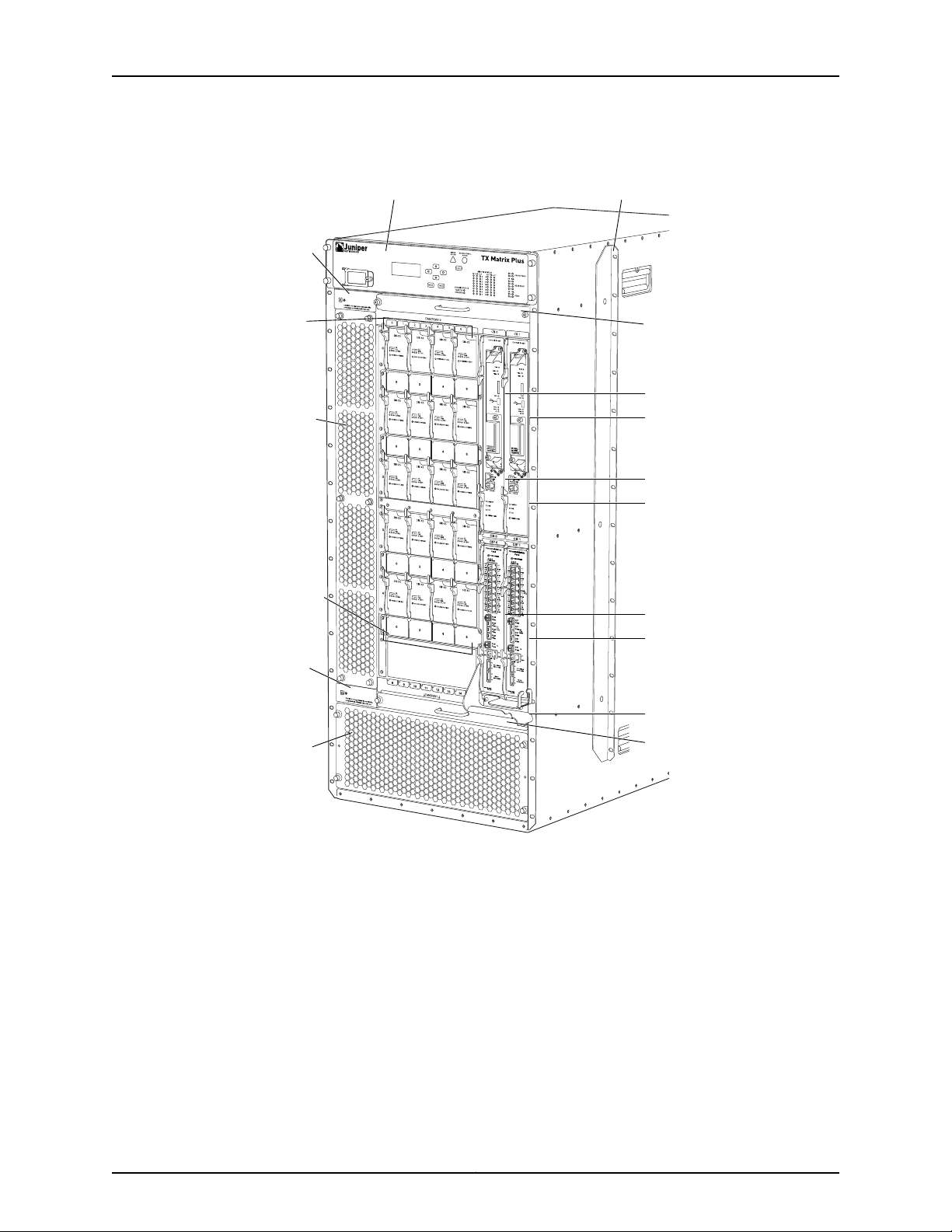
g004500
Air
intake
(air filter)
Air
intake
(2 air
filters)
Craft interface panel Center-mounting bracket
CB 0
CB 1
RE 0
CIP 0
RE 1
CIP 1
TXP-F2
SIBs
TXP-F2
SIBs
Fan tray 0
ESD
point
ESD
point
Fan tray 1
Front cable
manager
TX Matrix Plus Router Hardware Guide
Figure 2: Front View of the TX Matrix Plus Router
Copyright © 2010, Juniper Networks, Inc.10
Page 45

PEM1
g004501
Fan tray 4
Fan tray 2
Fan tray 3
PEM 1
PEM 0
Fan tray 5
Grounding
points
ESD point
ESD point
Air exhaust
Air exhaust
Air exhaust
TXP-F13
SIBs
TXP-F13
SIBs
Chapter 2: TX Matrix Plus Hardware Component Overview
Figure 3: Rear View of the TX Matrix Plus Router
Related
Documentation
Rack Requirements for a TX Matrix Plus Router on page 106•
• TX Matrix Plus Router Physical Specifications on page 431
• TX Matrix Plus Chassis Grounding Specifications on page 440
TX Matrix Plus Midplane Description
The midplane is located in the center of the chassis and forms the rear of the TXP-F2
SIB card cage (see Figure 4 on page 12). The TXP-F2S SIBs, TXP-CIPS, TXP-CBs, and
Routing Engines install into the midplane from the front of the chassis, and the TXP-F13
SIBs installinto themidplane fromthe rear of the chassis. The power supplies and cooling
system components also connect to the midplane.
11Copyright © 2010, Juniper Networks, Inc.
Page 46

g004508
Midplane
TX Matrix Plus Router Hardware Guide
The midplane performs the following major functions:
•
Power distribution—The TX Matrix power supplies are connected to the midplane,
which distributes power to all the TX Matrix components.
•
Signal connectivity—The midplane provides signal connectivity between all TX Matrix
components for monitoring and controlling the system.
•
Redundancy connectivity—The midplane provides redundant paths for all critical
connections.
Figure 4: TX Matrix Plus Router Midplane
Related
Documentation
TX Matrix Plus Router Description on page 3•
• TX Matrix Plus Switch-Fabric Chassis Description on page 8
• TX Matrix Plus Component Redundancy on page 7
Copyright © 2010, Juniper Networks, Inc.12
Page 47

TX Matrix Plus Switch Interface Boards Overview
g004502
•
TX Matrix Plus Switch Interface Boards Description on page 13
•
TX Matrix Plus TXP-F13 SIB Overview on page 13
•
TX Matrix Plus TXP-F13 SIB LEDs on page 15
•
TX Matrix Plus TXP-F2S SIB Overview on page 17
•
TX Matrix Plus TXP-F2S SIB LEDs on page 19
TX Matrix Plus Switch Interface Boards Description
The TX Matrix Plus Router containsTXP-F13 SIBsand TXP-F2SSIBs thatconnect together
through the midplane to create the switch fabric for the TX Matrix Plus router.
Chapter 2: TX Matrix Plus Hardware Component Overview
Related
Documentation
TX Matrix Plus TXP-F13 SIB Overview on page 13•
• TX Matrix Plus TXP-F2S SIB Overview on page 17
• Routing Matrix with a TX Matrix Plus Router Switch Fabric and Switching Plane
Architecture on page 60
TX Matrix Plus TXP-F13 SIB Overview
•
TXP-F13 SIB Description on page 13
•
TXP-F13 SIB Slots on page 14
TXP-F13 SIB Description
TXP-F13 SIBs are hot-removable and hot-insertable (see Figure 5 on page 13).
Figure 5: TXP-F13 SIB
Each TXP-F13 SIB consists of the following components:
•
Switch Fabric ASICs.
•
High-speed electrical links through the midplane to the TXP-F2S SIBs on the same
switching plane.
13Copyright © 2010, Juniper Networks, Inc.
Page 48

TX Matrix Plus Router Hardware Guide
These components are located on the TXP-F13 faceplate:
•
Eight high-speed fiber-optic links connect to two T1600 routers in the routing matrix.
The left four ports are labeled EVEN and provide connections to one even-numbered
LCC—LCC0 or LCC2.The right four ports are labeled ODD and provide connections to
one odd-numbered LCC—LCC1 or LCC3. The four ports on each side are labeled CBL
A, CBL B, CBL C and CBL D.
•
Three ONLINE/OFFLINE buttons are located in the middle of the TXP-F13 SIB.
•
•
•
•
Three status LEDs, labeled ACTIVE, OK and FAIL, located below the ONLINE/OFFLINE
buttons.
The ONLINE/OFFLINE button labled LCC EVEN brings the corresponding interface
and TXP-T1600 SIB on the even T1600 router online and offline.
The ONLINE/OFFLINE button labled LCC ODD brings the corresponding interface
and TXP-T1600 SIB on the odd T1600 router online and offline.
The ONLINE/OFFLINE button in the center labeled SIB brings the TXP-F13 SIB online
and offline.
•
Two port LEDs, labeled LINK and RxPWR, located to the right of each fiber-optic array
port.
Three LEDs, labeled OK , FAIL, and ACTIVE are located on the craft interface; they show
the status of the link to the T1600 router.
TXP-F13 SIB Slots
Sixteen horizontal TXP-F13 SIB slots numbered 0 through 15 (top to bottom) are located
in the rear of the TX Matrix Plus router. A TXP-4 configuration contains ten TXP-F13 SIBs,
two for each data switching plane. The remaining slots are unused.
Table 3: TXP-F13 SIB Slots
PlaneTXP-F13 SIB NameTXP-F13 SIB Slot
0SIB F13 0Slot 0
SIB F13 1Slot 1
–UnusedSlot 2
1SIB F13 3Slot 3
SIB F13 4Slot 4
–UnusedSlot 5
2SIB F13 6Slot 6
SIB F13 7Slot 7
Copyright © 2010, Juniper Networks, Inc.14
Page 49

g004503
Port LEDs
Rx Optical Power
Link Status
Chapter 2: TX Matrix Plus Hardware Component Overview
Table 3: TXP-F13 SIB Slots (continued)
SIB F13 9Slot 9
SIB F13 12Slot 12
PlaneTXP-F13 SIB NameTXP-F13 SIB Slot
3SIB F13 8Slot 8
–UnusedSlot 10
4SIB F13 11Slot 11
–UnusedSlot 13
–UnusedSlot 14
–UnusedSlot 15
Related
Documentation
Routing Matrix with a TX Matrix Plus Router Switch Fabric and Switching Plane
•
Architecture on page 60
• TX Matrix Plus TXP-F13 SIB LEDs on page 15
• Maintaining the TX Matrix Plus SIBs on page 269
• Troubleshooting the TX Matrix Plus SIBs on page 294
• Troubleshooting the Switching Planes in the Routing Matrix on page 305
TX Matrix Plus TXP-F13 SIB LEDs
The TXP-F13 status LEDs (Figure 6 on page 15) are located below the ONLINE/OFFLINE
buttons. Table 7 on page 19 describes the functions of these LEDs.
Figure 6: TXP-F13 SIB LEDs
15Copyright © 2010, Juniper Networks, Inc.
Page 50

TX Matrix Plus Router Hardware Guide
Table 4: TXP-F13 SIB LEDs
The port LEDs are located next to the ports. Table 5 on page 16 describes the functions
of these LEDs.
DescriptionStateColorLabel
TXP-F13 SIB is in active mode and actively passing traffic.On steadilyGreenACTIVE
TXP-F13 SIB is either offline or not actively passing traffic.Off–
TXP-F13 SIB is functioning normally.On steadilyGreenOK
TXP-F13 SIB is offline or not seated properly.Off–
TXP-F13 SIB has failed.On steadilyYellowFAIL
No faults have been detected for the TXP-F13 SIB.Off–
Table 5: F13-SIB Port LEDs
On steadilyGreenLINK
Blinking
Blinking
On steadilyRed
Off–
On steadilyYellow
DescriptionStateColorLabel
The link between the TXP-F13 SIB port and the TXP-T1600 SIB
port has been established successfully.
The link between the TXP-F13 SIB port and the loopback
connector has been established successfully.
The link is being established.On steadilyYellow
The fiber-optic array cable might be connected to either the
wrong TXP-T1600 SIB port or wrong TXP-FI3 port.
The link between the TXP-F13 SIB port and the TXP-T1600 SIB
port failed. There might bea hardware problem, orthe fiber-optic
port or cable might need to be cleaned.
The cable is not connected on both sides, or either the TXP-F13
SIB or TXP-T1600 SIB is powered off.
Full optical power is being received.On steadilyGreenRxPWR
Diminished opticalpower isbeing received. The fiber-optic array
cable or the fiber-optic array port might need cleaning, or the
cable might be damaged.
Off–
No optical power has been received. The fiber-optic array cable
is not connected to the TXP-FI3 SIB port, or not connected to
the TXP-T1600 SIB port. If the cable is connected on both sides,
the cable might be cut.
Copyright © 2010, Juniper Networks, Inc.16
Page 51

g004504
Chapter 2: TX Matrix Plus Hardware Component Overview
Related
Documentation
Routing Matrix with a TX Matrix Plus Router Switch Fabric and Switching Plane
•
Architecture on page 60
• Maintaining the TX Matrix Plus SIBs on page 269
• Troubleshooting the TX Matrix Plus SIBs on page 294
• Troubleshooting the Switching Planes in the Routing Matrix on page 305
TX Matrix Plus TXP-F2S SIB Overview
•
TXP-F2S SIB Components on page 17
•
TXP-F2S SIB Slots on page 17
TXP-F2S SIB Components
TXP-F2S SIBs are hot-removable and hot-insertable (see Figure 7 on page 17).
Figure 7: TXP-F2S SIB
Each TXP-F2S SIB consists of the following components:
•
Switch Fabric ASICs.
•
High-speed links through the midplane to the TXP-FI3 SIBs.
These components are located on the TXP-F2S faceplate:
•
Three status LEDs—FAIL, OK, and ACTIVE .
•
One ONLINE/OFFLINE button located below the status LEDs.
TXP-F2S SIB Slots
Twenty vertical TXP-F2S SIB slots are located in the front of the TX Matrix Plus router.
A TXP-4 configuration contains four TXP-F2 SIBs for each data switching plane (see
Table 6 on page 18).
17Copyright © 2010, Juniper Networks, Inc.
Page 52

TX Matrix Plus Router Hardware Guide
Table 6: TXP-F2 SIB Slots
PlaneTXP-SIB2 NameTXP-SIB2 Slot
0sib f2s 0/0Slot 0/0
sib f2s 0/2Slot 0/2
sib f2s 0/4Slot 0/4
sib f2s 0/6Slot 0/6
1sib f2s 1/0Slot 1/0
sib f2s 1/2Slot 1/2
sib f2s 1/4Slot 1/4
sib f2s 1/6Slot 1/6
2sib f2s 2/0Slot 2/0
sib f2s 2/2Slot 2/2
sib f2s 2/4Slot 2/4
sib f2s 2/6Slot 2/6
3sib f2s 3/0Slot 3/0
sib f2s 3/2Slot 3/2
sib f2s 3/4Slot 3/4
sib f2s 3/6Slot 3/6
4sib f2s 4/0Slot 4/0
sib f2s 4/2Slot 4/2
sib f2s 4/4Slot 4/4
sib f2s 4/6Slot 4/6
Related
Documentation
TX Matrix Plus TXP-F2S SIB LEDs on page 19•
• Routing Matrix with a TX Matrix Plus Router Switch Fabric and Switching Plane
Architecture on page 60
• Maintaining the TX Matrix Plus SIBs on page 269
• Troubleshooting the TX Matrix Plus SIBs on page 294
Copyright © 2010, Juniper Networks, Inc.18
Page 53

• Troubleshooting the Switching Planes in the Routing Matrix on page 305
g004505
TX Matrix Plus TXP-F2S SIB LEDs
The status LEDs (Figure 8 on page 19) are located above the ONLINE/OFFLINE button.
Table 7 on page 19 describes the functions of these LEDs.
Figure 8: TXP-F2S SIB Faceplate
Chapter 2: TX Matrix Plus Hardware Component Overview
Related
Documentation
Table 7: F13 SIB LEDs
DescriptionStateColorLabel
TXP-F2S SIB is functioning normally.On steadilyGreenOK
TXP-F2S SIB is starting up.Blinking
TXP-F2S SIB is offline or not seated properly.Off–
On steadilyGreenACTIVE
TX Matrix Plus TXP-F2S SIB Overview on page 17•
• Routing Matrix with a TX Matrix Plus Router Switch Fabric and Switching Plane
Architecture on page 60
• Maintaining the TX Matrix Plus SIBs on page 269
TXP-F2S SIB is in active mode and actively passing
traffic.
TXP-F2S SIB is offline or not actively passing traffic.Off–
TXP-F2S SIB has failed.On steadilyYellowFAIL
No faults have been detected for the TXP-F2S SIB.Off–
• Troubleshooting the TX Matrix Plus SIBs on page 294
• Troubleshooting the Switching Planes in the Routing Matrix on page 305
19Copyright © 2010, Juniper Networks, Inc.
Page 54

TX Matrix Plus Router Hardware Guide
TX Matrix Plus Host Subsystem Overview
•
TX Matrix Plus Host Subsystem Description on page 20
•
TX Matrix Plus Control Board Description on page 20
•
TX Matrix Plus TXP-CB Overview on page 21
•
TX Matrix Plus TXP-CB LEDs on page 23
•
TX Matrix Plus Routing Engine Description on page 25
•
TX Matrix Plus RE-C2600 Routing Engine Overview on page 26
•
TX Matrix Plus RE-C2600 LEDs on page 28
TX Matrix Plus Host Subsystem Description
The host subsystem provides the routing and system management functions of the TX
Matrix Plus router. You can install one or two host subsystems on the TX Matrix Plus
router. A host subsystem consists of a Routing Engine installed directly into a slot in a
control board. To operate, each host subsystem functions as a unit; the Routing Engine
requires the corresponding control board, and vice versa.
NOTE: We recommend that you install two host subsystems for redundant
protection. If you install only one host subsystem, we recommend that you
install it in slot CB0.
Related
Documentation
TX Matrix Plus Control Board Description on page 20•
• TX Matrix Plus TXP-CB Overview on page 21
• TX Matrix Plus Routing Engine Description on page 25
• TX Matrix Plus RE-C2600 Routing Engine Overview on page 26
TX Matrix Plus Control Board Description
You can install up to two control boards in the TX Matrix Plus Router. Control boards
install into the upper front of the chassis in the slots labeled CB0 and CB1 (referred to as
CB-0 and CB-1). A Routing Engine installs directly into a slot on each control board. The
control boards can not function if a Routing Engine is not present.
Each control board works with the Routing Engine to provide the following control and
monitoring functions for the TX Matrix Plus router:
•
Determining Routing Engine mastership
•
Controlling power and reset for the other TX Matrix Plus components
•
Monitoring and controlling fan speed
•
Monitoring system status.
Copyright © 2010, Juniper Networks, Inc.20
Page 55

Chapter 2: TX Matrix Plus Hardware Component Overview
If the TX Matrix Plus router contains a redundant host subsystem, one TXP-CB functions
as the master and the other as its backup. If the master fails or is removed, the backup
restarts and becomes the master.
The TX Matrix Plus router supports the TXP-CB.
Related
Documentation
TX Matrix Plus Host Subsystem Description on page 20•
• TX Matrix Plus TXP-CB Overview on page 21
• TX Matrix Plus Routing Engine Description on page 25
TX Matrix Plus TXP-CB Overview
•
TXP-CB Description on page 21
•
Routing Engine Ports on the TXP-CB on page 23
TXP-CB Description
Each TXP-CB (see Figure 9 on page 22) works with the Routing Engine to provide the
following control and monitoring functions for the TX Matrix Plus router.
21Copyright © 2010, Juniper Networks, Inc.
Page 56

g004509
ONLINE/OFFLINE
button
Status LEDs
Routing Engine
ETHERNET
port ACT LED
ETHERNET
port speed LED
Y = 10/100
G = 1000
TX Matrix Plus Router Hardware Guide
Figure 9: TXP-CB
Each TXP-CB consists of the following components:
•
1-GB Ethernet switch used for intermodule communication.
•
PCI bus to the Routing Engines.
•
Switch Processor Mezzanine Board (SPMB).
These components are located on the TXP-CB faceplate:
•
Three Routing Engine ports—ETHERNET, CONSOLE, and AUXILIARY—located below
the Routing Engine,for connecting the Routing Engineto external managementdevices.
•
Two port LEDs—ETHERNET and ACT—located next to the ETHERNET port indicate the
port status and speed.
•
Three status LEDs—MASTER, FAIL, and OK— indicate the status of the TXP-CB.
•
Online/offline button, located below the status LEDs..
Copyright © 2010, Juniper Networks, Inc.22
Page 57

Chapter 2: TX Matrix Plus Hardware Component Overview
Routing Engine Ports on the TXP-CB
Each TXP-CB has a set of ports that you use to connect the Routing Engines to external
management devices (see Figure 19 on page 37). From these management devices, you
can use the CLI to configure and manage the TX Matrix Plus router.
The management ports on each TXP-CB connect to the Routing Engine iinstalled into
that TXP-CB. Each TXP-CB includes the following ports:
•
ETHERNET—10/100-Mbps/1-Gbps Ethernet port for connecting to a management
network. Connects the Routing Engine through an Ethernet connection to a
management LAN (or any other device that plugs into an Ethernet connection) for
management of the routing matrix. The port uses an autosensing RJ-45 connector to
support 10-Mbps, 100-Mbps, or 1-Gbps connections. Two small LEDs on the left edge
of the port indicate the connection in use.
•
CONSOLE—One asynchronous serial port for connecting to a console. Connects the
Routing Engine to a system console through an RS-232 (EIA-232) serial cable.
•
AUXILIARY—One asynchronous serial port for connecting toa modemor other auxiliary
device. Connects the Routing Engine to a laptop, modem, or other auxiliary device
through an RS-232 (EIA-232) serial cable.
Related
Documentation
TX Matrix Plus Host Subsystem Description on page 20•
• TX Matrix Plus TXP-CB LEDs on page 23
• TX Matrix Plus Routing Engine Description on page 25
• TX Matrix Plus Routing Engine Interface Cable Specifications on page 443
• RJ-45 Connector Pinouts for the TX Matrix Plus Routing Engine ETHERNET Port on
page 445
• RJ-45 Connector Pinouts for the TX Matrix Plus Routing Engine AUXILIARY and
CONSOLE Ports on page 446
TX Matrix Plus TXP-CB LEDs
The LEDs located on the bottom of the TXP-CB indicate its status. Table 8 on page 24
describes the functions of the TXP-CB LEDs.
NOTE: If a TX Matrix Plus routercontains twohost subsystems,connectboth
TXP-CBs to your external management network.
23Copyright © 2010, Juniper Networks, Inc.
Page 58

g004509
ONLINE/OFFLINE
button
Status LEDs
Routing Engine
ETHERNET
port ACT LED
ETHERNET
port speed LED
Y = 10/100
G = 1000
TX Matrix Plus Router Hardware Guide
Figure 10: TXP-CB
Table 8: TXP-CB LEDs
DescriptionStateColorLabel
TXP-CB is functioning as the master.On steadilyBlueMASTER
TXP-CB is functioning as the backup.Off–
TXP-CB has failed.On steadilyYellowFAIL
No faults have been detected on the TXP-CB.Off–
TXP-CB is online and is functioning normally.On steadilyGreenOK
TXP-CB is powering up, but not online.Blinking
TXP-CB is offline.Off–
Copyright © 2010, Juniper Networks, Inc.24
Page 59

Chapter 2: TX Matrix Plus Hardware Component Overview
Table 8: TXP-CB LEDs (continued)
DescriptionStateColorLabel
1-Gbps connectionOn steadilyGreenETHERNET
10/100-Mbps connectionOn steadilyYellow
TXP-CB is offline.Off–
Traffic is passing through the port.On steadilyGreenACT
No traffic is passing through the port.Off–
Related
Documentation
TX Matrix Plus TXP-CB Overview on page 21•
• Maintaining the TX Matrix Plus TXP-CBs on page 268
• Troubleshooting the TX Matrix Plus Host Subsystem on page 311
• Troubleshooting the TX Matrix Plus TXP-CBs on page 311
TX Matrix Plus Routing Engine Description
You can install one or two Routing Engines in the TX Matrix Plus router. The Routing
Engines install into the control boards labeled CB0 and CB1. If two Routing Engines are
installed, one functions as the master and the other acts as the backup. If the master
Routing Engine failsor is removed andthe backupis configured appropriately, the backup
restarts and becomes the master.
NOTE: Nonstop active routing is supported for the TX Matrix Plus router in
Junos OS Release 10.0 and later.
The TX Matrix Routing Engine constructs and maintains one ormore routingtables. From
the routingtables, the Routing Engine derives a tableof activeroutes, called theforwarding
table, which is then copied to the T1600 routers. TheJunos kernel running on each T1600
Routing Engine copies its forwarding table to all Packet Forwarding Engines in the router.
The design of the ASICs allows the forwarding table in the Packet Forwarding Engine to
be updated without interrupting forwarding performance.
The TX Matrix Plus Routing Engines handle all routing protocols, as well as the software
processes that control the interfaces in the TX Matrix Plus router and user access to the
TX Matrix Plus router. All Routing Engines in the routing matrix run software processes
that control chassis components and system management.
The Routing Engines include the following functions and features:
25Copyright © 2010, Juniper Networks, Inc.
Page 60

TX Matrix Plus Router Hardware Guide
•
Processing of routing protocol packets—The Routing Engine handles all packets that
concern routing protocols, freeingthe Packet Forwarding Engine to handleonly packets
that represent Internet traffic.
•
Softwaremodularity—Becauseeach software process is devoted to a different function
and uses a separate process space, the failure of one process has little or no effect on
the others.
•
In-depth Internet functionality—Each routingprotocolis implemented witha complete
set ofInternet features and provides full flexibilityfor advertising, filtering,and modifying
routes. Routing policies are set according to route parameters (for example, prefix,
prefix lengths, and Border Gateway Protocol [BGP] attributes).
•
Scalability—The Junos routing tables have been designed to hold all the routes in
current networks with ample capacity for expansion. Additionally, the Junos OS can
efficiently support large numbers of interfaces and virtual circuits.
•
Management interface—Different levels of system management tools are provided,
including the Junos OS command-line interface (CLI), the Junos XML management
protocol, the craft interface, and SNMP.
•
Storage andchange management—Configurationfiles, system images, andmicrocode
can be held and maintained in primary and secondary storage systems, permitting
local or remote upgrades.
•
Monitoring efficiency and flexibility—The TX Matrix Plusrouter supports functions such
as alarm handling and packet counting on every port, without degrading
packet-forwarding performance.
Related
Documentation
TX Matrix Plus Host Subsystem Description on page 20•
• TX Matrix Plus RE-C2600 Routing Engine Overview on page 26
• Routing Matrix with a TX Matrix Plus Router System Architecture on page 55
TX Matrix Plus RE-C2600 Routing Engine Overview
•
RE-C2600 Description on page 26
•
RE-C2600 Boot Sequence on page 28
RE-C2600 Description
Each RE-C2600 (shown in Figure 11 on page 27) consists of the following components:
•
CPU—Runs Junos OS to maintain the TX Matrix Plus routing tables and routing
protocols.
•
DRAM—Provides storage for the routing and forwarding tables and for other Routing
Engine processes.
•
EEPROM—Stores the serial number of the Routing Engine.
•
Interfaces for management access—Provide information about Routing Engine status
to the external management devices (console, laptop, or terminal server) connected
to the TXP Routing Engine ports located below the Routing Engine on the TXP-CB.
Copyright © 2010, Juniper Networks, Inc.26
Page 61

Figure 11: RE-C2600
g004506
Chapter 2: TX Matrix Plus Hardware Component Overview
The faceplate of the RE-C2600 contains the following:
•
USB port USB—Provides a removable media interface through which you can install
the Junos OS manually. Junos supports USB versions 2.0 and 1.1.
•
CompactFlash card slot CF (shown in Figure 12 on page 28)—Provides primary storage
for software images, configuration files, and microcode.
•
Two solid-state disk slots SSD1 and SSD2 (shown in Figure 12 on page 28)—Provides
secondary storage for log files, memory dumps, and rebooting the system if the
CompactFlash card fails.
NOTE: SSD2 is not currently supported.
•
Reset button—Reboots the Routing Engine when pressed.
•
Offline button—Takes the Routing Engine offline when pressed.
•
Extractor clips—Control the locking system that secures the Routing Engine.
•
LEDs—“TX Matrix Plus RE-C2600 LEDs” on page 28 describes the functions of these
LEDs.
NOTE: For specific information about Routing Engine components (for
example, the amount of DRAM), issue the show chassis routing-engine
command.
27Copyright © 2010, Juniper Networks, Inc.
Page 62

g004527
TX Matrix Plus Router Hardware Guide
Figure 12: RE-C2600 CompactFlash Card and Solid-State Disk Slots
RE-C2600 Boot Sequence
The RE-C2600 boots from the storage media in this order: the USB device (if present),
the CompactFlash card CF (if present), the disk (if present) in slot 1 SSD1, the disk (if
present) in slot 2 SSD2, then the LAN.
Related
Documentation
Providing Power to a Seven-Input 420-A Power Supply on page 167•
• Maintaining the TX Matrix Plus Routing Engines on page 268
• Troubleshooting the TX Matrix Plus Host Subsystem on page 311
• Troubleshooting the TX Matrix Plus Routing Engines on page 312
TX Matrix Plus RE-C2600 LEDs
Four LEDs—ONLINE, CF, SSD1, and SSD2—indicate the status of the RE-C2600 (see
Figure 13 on page 29 and Table 15 on page 39).
NOTE: SSD2 is not currently supported.
Copyright © 2010, Juniper Networks, Inc.28
Page 63

Figure 13: RE-C2600 LEDs
g004507
Chapter 2: TX Matrix Plus Hardware Component Overview
NOTE: The LEDs on the Routing Engine do not necessarily indicate
routing-related activity.
Table 9: RE-C2600 LEDs
Off–
DescriptionStateColorLabel
Routing Engine is functioning normally.On steadilyGreenONLINE
Routing Engine is not functioning normally.On steadilyRed
Routing Engine is not online or not functioning
normally.
Indicates disk activity.On steadilyBlueSSD1
There is no disk activity.Off–
Indicates disk activity.On steadilyBlueSSD2
There is no disk activity.Off–
Indicates activity for the CompactFlash card.On steadilyGreenCF
There is no activity forthe CompactFlash card.Off–
29Copyright © 2010, Juniper Networks, Inc.
Page 64

g004510
Chassis
status
LEDs
Chassis
ID switch
cover
SIB-F13
status
LEDs
Fan and
PEM
LEDs
LCD
display
Menu
Buttons
Alarm LEDS
TX Matrix Plus Router Hardware Guide
Related
Documentation
TX Matrix Plus RE-C2600 Routing Engine Overview on page 26•
• Troubleshooting the TX Matrix Plus Host Subsystem on page 311
• Troubleshooting the TX Matrix Plus Routing Engines on page 312
TX Matrix Plus Craft Interface Overview
•
Craft Interface Front Panel on page 30
•
LCD Modes on page 31
•
LCD Navigation Buttons on page 32
•
Alarm Cutoff/Lamp Test Button on page 32
Craft Interface Front Panel
The craft interface allows you to view status and troubleshooting information at a glance
and to perform many system control functions. It is hot-insertable and hot-removable.
The craft interface is located at the upper front of the TX Matrix Plus router.
Figure 14: Front Panel of the TX Matrix Plus Craft Interface
The front panel of the craft interface contains:
•
SFC chassis number.
•
Configuration (config) size.
•
A four-line LCD display, along with six navigation buttons. The LCD display operates
in Idle mode or alarm mode.
•
Yellow Minor Alarm LED, red Major Critical Alarm LED.
•
Alarm cutoff/lamp test ACO/LT button.
•
Chassis Status Master and Standby LEDs.
•
OK, FAIL, and ACT LEDs for each TXP-F13 SIB.
•
OK and FAIL LEDs for the front and rear fan trays.
•
OK and FAIL LEDs for each power supply.
Copyright © 2010, Juniper Networks, Inc.30
Page 65

LCD Modes
g004511
g004512
Chapter 2: TX Matrix Plus Hardware Component Overview
•
LCD Display Idle Mode on page 31
•
LCD Display Alarm Mode on page 31
LCD Display Idle Mode
During normaloperation, the LCD display operates in idle mode and reports current status
information, as shown in Figure 15 on page 31.
Figure 15: LCD Display in Idle Mode
The lines in the display report the following information:
•
First line—TX Matrix Plus router name.
•
Second line—Length of time the TX Matrix Plus router has been running, reported in
the following form:
Up days + hours:minutes
•
Third and fourth lines—Status messages, which rotate at 2-second intervals. Some
conditions, such as removal or insertion of a system component, can interrupt the
messages.
To add a message that alternates every 2 seconds with the default status messages,
use the set chassis display message command. For more information, see the Junos OS
System Basics Configuration Guide.
LCD Display Alarm Mode
When a red or yellow alarm occurs, the LCD display switches to alarm mode and reports
about the alarm condition, as shown in Figure 16 on page 31.
Figure 16: LCD Display in Alarm Mode
The lines in the display report the following information:
•
First line—TX Matrix Plus router name.
31Copyright © 2010, Juniper Networks, Inc.
Page 66

TX Matrix Plus Router Hardware Guide
•
Second line—Number of active alarms.
•
Third and fourth lines—Individual alarm messages, with the most severe condition
shown first. Theprefix on each line indicates whether the alarm is ared (R)or yellow (Y)
alarm.
LCD Navigation Buttons
The LCD Display has the following navigation buttons:
•
Menu button
•
Enter button
•
Four arrow buttons for scrolling up or down, and left or right
Alarm Cutoff/Lamp Test Button
The alarm cutoff/lamp test button labeled ACO/LT is located below the alarm LEDs.
Figure 17 on page 32 shows the alarm cutoff button.
Figure 17: Alarm Cutoff/Lamp Test Button
Use the ACO/LT button to deactivate the red and yellow alarms. Pressing the button
turns off both LEDs and deactivates the device attached to the corresponding alarm
relay contact on the TXP-CIP. However, the LCD display continues to report the alarm
message until the condition that caused the alarm is cleared.
To test the LEDs on the craft interface, press and hold the ACO/LT button. All the LEDs
on the craft interface should light.
Related
Documentation
Deactivating Alarms on the TX Matrix Plus Craft Interface on page 279•
• Displaying TX Matrix Plus SFC and LCC Alarm Messages Information on page 280
• Alarm LEDs on the TX Matrix Plus Craft Interface on page 33
• Chassis Status LEDs on the TX Matrix Plus Craft Interface on page 34
• TXP-F13 SIB LEDs on the TX Matrix Plus Craft Interface on page 34
• Fan Tray LEDs on the TX Matrix Plus Craft Interface on page 35
• Power Supply LEDs on the TX Matrix Plus Craft Interface on page 35
TX Matrix Plus Craft Interface LED Overview
•
Alarm LEDs on the TX Matrix Plus Craft Interface on page 33
•
Chassis Status LEDs on the TX Matrix Plus Craft Interface on page 34
•
TXP-F13 SIB LEDs on the TX Matrix Plus Craft Interface on page 34
Copyright © 2010, Juniper Networks, Inc.32
Page 67

•
g004510
Chassis
status
LEDs
Chassis
ID switch
cover
SIB-F13
status
LEDs
Fan and
PEM
LEDs
LCD
display
Menu
Buttons
Alarm LEDS
Fan Tray LEDs on the TX Matrix Plus Craft Interface on page 35
•
Power Supply LEDs on the TX Matrix Plus Craft Interface on page 35
Alarm LEDs on the TX Matrix Plus Craft Interface
Two large alarm LEDs are located on the craft interface (see Figure 18 on page 33) Both
LEDs can be lit simultaneously.
Figure 18: Alarm LEDs on the TX Matrix Plus Craft Interface
Chapter 2: TX Matrix Plus Hardware Component Overview
Related
Documentation
•
The circular red LED lights to indicate a critical condition that can result in a system
shutdown.
•
The triangular yellow LED lights to indicate a less severe condition that requires
monitoring or maintenance.
The LCD display on the craft interface reports the cause of the alarm. A condition that
causes an alarm LED to light also activates the corresponding alarm relay contact on
the connector interface panel (TXP-CIP).
Table 10 on page 33 describes the alarm LEDs.
Table 10: Alarm LEDs on the TX Matrix Plus Craft Interface
DescriptionStateColorShape
On steadilyRed
On steadilyYellow
TX Matrix Plus TXP-CIP Overview on page 36•
• TX Matrix Plus Craft Interface Overview on page 30
• Deactivating Alarms on the TX Matrix Plus Craft Interface on page 279
Critical alarm LED—Indicates a critical condition that
can cause the TX Matrix Plus router to stop
functioning. Possible causes include component
removal, failure, or overheating.
Warningalarm LED—Indicates aserious but nonfatal
error condition, such as a maintenance alert or a
significant increase in component temperature.
• Displaying TX Matrix Plus SFC and LCC Alarm Messages Information on page 280
33Copyright © 2010, Juniper Networks, Inc.
Page 68

TX Matrix Plus Router Hardware Guide
Chassis Status LEDs on the TX Matrix Plus Craft Interface
Two LEDs located in the middle of craft interface below the Alarm LEDs indicate whether
the TX Matrix Plus router is functioning as the master for the routing matrix. Table 11 on
page 34 describes the functions of the Chassis Status LEDs.
Table 11: Chassis Status LEDs on the TX Matrix Plus Craft Interface
DescriptionStateColorLabel
On steadilyGreenMASTER
Off–
STANDBY
NOTE: This LED is reserved for future use.
Related
Documentation
TX Matrix Plus Switch-Fabric Chassis Description on page 8•
• TX Matrix Plus Craft Interface Overview on page 30
TXP-F13 SIB LEDs on the TX Matrix Plus Craft Interface
The right side of the craft interface has three LEDs for each TXP-F13 SIB that indicate
the status of that SIB. The corresponding TXP-F13 SIB slots are labeled 0 through 15.
Table 12 on page 34 describes the functions of the TXP-F13 SIB LEDs.
Table 12: TXP-F13 SIB LEDs on the TX Matrix Plus Craft Interface
The TX Matrix Plus routeris functioning asthe master
SFC for the routing matrix. For the A4 configuration,
this LED should always be lit when the router is
receiving power.
For the A4 configuration, the TX Matrix Plus router
might not be receiving power.
DescriptionStateColorLabel
TXP-F13 SIB is functioning normally.On steadilyGreenOK
TXP-F13 SIB is coming online.Blinking
TXP-F13 SIB is not functioning normally.Off–
TXP-F13 SIB has failed.On steadilyRedFAIL
No faults have been detected for the TXP-F13 SIB.Off–
On steadilyGreenACTIVE
Off–
TXP-F13 SIB is in active mode and actively passing
traffic.
TXP-F13 SIB is either offline or not actively passing
traffic.
Copyright © 2010, Juniper Networks, Inc.34
Page 69

Chapter 2: TX Matrix Plus Hardware Component Overview
Related
Documentation
TX Matrix Plus Craft Interface Overview on page 30•
• TX Matrix Plus TXP-F13 SIB Overview on page 13
• TX Matrix Plus TXP-F13 SIB LEDs on page 15
• Troubleshooting the TX Matrix Plus SIBs on page 294
• Troubleshooting the Switching Planes in the Routing Matrix on page 305
Fan Tray LEDs on the TX Matrix Plus Craft Interface
Two status LEDs for each of the front fan tray and the rear fan trays are located on the
right of the craft interface.
Table 13: Fan Tray LEDs on the TX Matrix Plus Craft Interface
DescriptionStateColorLabel
The fan tray is functioning normally.On steadilyGreenOK
The fan tray is not functioning normally.Off–
The fan tray has failed.On steadilyRedFAIL
No faults have been detected for the fan tray.Off–
Related
Documentation
TX Matrix Plus Craft Interface Overview on page 30•
• TX Matrix Plus Cooling System Overview on page 45
• Troubleshooting the TX Matrix Plus Cooling System on page 283
Power Supply LEDs on the TX Matrix Plus Craft Interface
Two status LEDs—labeled PEM—for each power supply are located on the right of the
craft interface.
Table 14: Power Supply LEDs on the TX Matrix Plus Craft Interface
Related
Documentation
TX Matrix Plus Craft Interface Overview on page 30•
• TX Matrix Plus Seven-Input 420-A Power Supplies Overview on page 41
DescriptionStateColorLabel
The power supply is functioning normally.On steadilyGreenOK
The power supply is not functioning normally.Off–
The power supply has failed.On steadilyRedFAIL
No faults have been detected for the power supply.Off–
35Copyright © 2010, Juniper Networks, Inc.
Page 70

TX Matrix Plus Router Hardware Guide
• TX Matrix Plus Seven-Input 420-A Power Supply LEDs on page 43
• Troubleshooting the TX Matrix Plus Power System on page 290
TX Matrix Plus Connector Interface Panel Overview
•
TX Matrix Plus Connector Interface Panel Description on page 36
•
TX Matrix Plus TXP-CIP Overview on page 36
•
TX Matrix Plus TXP-CIP LEDs on page 39
TX Matrix Plus Connector Interface Panel Description
The TX Matrix Plus routercontains two connector interface panels—onefor eachRouting
Engine—that install vertically belowthe host subsystem intothe front right of the chassis
in the slots labeled CIP0 and CIP1.
The TX Matrix Plus router supports the TXP-CIP.
Related
Documentation
TX Matrix Plus Router Description on page 3•
• TX Matrix Plus TXP-CIP Overview on page 36
• TX Matrix Plus TXP-CIP LEDs on page 39
TX Matrix Plus TXP-CIP Overview
•
TXP-CIP Components on page 36
•
TXP-CIP Ports on page 37
•
TXP-CIP Alarm Relay Contacts on page 38
TXP-CIP Components
The TXP-CIPs (see Figure 19 on page 37) are referred to as TXP-CIP-0 and TXP-CIP-1.
Copyright © 2010, Juniper Networks, Inc.36
Page 71

Figure 19: TX Matrix Plus TXP-CIP
SPEED:YEL=10/100
GRN=1000
NO
C
NC
NO
C
NC
g004513
ONLINE/OFFLINE
button
LCC Control
plane ports
Status LEDs
SFC Control
plane ports
Alarm relay
connectors
Chapter 2: TX Matrix Plus Hardware Component Overview
Each TXP-CIP houses:
•
Ports for connections to the LCC control plane, SFC control plane, and other devices.
NOTE: The SFC control plane ports are reserved for future use.
•
Alarm relay contacts
•
Three LEDs—ACTIVE, OK, FAIL— that indicate the status of the TXP-CIP.
•
ACT and SPEED port LEDs for the LCC CTRL PLANE ports 0 through 15
•
Port LEDs for the reserved ports 16 and 17
•
ACT and LINK port LEDs for the SFC CTRL PLANE ports XGE0 through XGE4
The TXP-CIPs are hot-removable and hot-insertable.
TXP-CIP Ports
LCC Control Plane Ports
Control plane connections to the T1600 routers in the routing matrix are provided by
sixteen 10/100/1000 Base-T copper RJ-45 LCC control plane ports labeled LCC CTRL
PLANE 0 through 15 on the TXP-CIP. UTP Category 5E Ethernet cables connect the LCC
CTRL PLANE ports in TXP-CIP-0 and TXP-CIP-1 to the LCC-CBs LCC-CB-0 and LCC-CB-1
in each T1600 router. For more information about connecting TXP-CIPs to LCC-CBs, see
37Copyright © 2010, Juniper Networks, Inc.
Page 72

TX Matrix Plus Router Hardware Guide
“Control Plane Connections from the TX Matrix Plus Router to the T1600 Routers” on
page 58.
Reserved Ports
Each TXP-CIP contains two copper RJ-45 ports, labeled 16 and 17,that are reserved for
future use.
SFC Control Plane Ports
Each TXP-CIP contains five 10-Gigabit Ethernet SFP+ ports labeled SFC CTRL PLANE
XGE0 through XGE4.
NOTE: The ports labeled 4 through 15 on a TXP-CIP are reserved for future
use.
NOTE: These ports are reserved for future use.
Related
Documentation
TXP-CIP Alarm Relay Contacts
Each TXP-CIP has two alarm relay contacts—labeled RED ALARM and YELLOW ALARM
(see Figure 19 on page 37), located on the bottom of the TXP-CIP. You can connect the
TX Matrix Plus router to external alarm-reporting devices by attaching wires to the alarm
relay contacts.
NOTE: If your TX Matrix Plus router contains two host subsystems, we
recommend that you connect each relay contact on each TXP-CIP to a
separate reporting device.
The terminal blocks that plug into the alarm relay contacts are supplied with the TX
Matrix Plus router. They accept wire of any gauge between 28-AWG and 14-AWG (0.08
and 2.08 mm2), which is not provided. Use the wire gauge appropriate for the external
device you are connecting.
Whenever a system condition triggers eitherthe redor yellow alarm on the craftinterface,
the corresponding alarm relay contacts are also activated. The alarms on TXP-CIP-0and
TXP-CIP-1 correspond to the Routing Engines installed into the TXP-CBs in slots CB0
and CB1.
TX Matrix Plus TXP-CIP LEDs on page 39•
• Troubleshooting the TX Matrix Plus TXP-CIPs on page 309
• Replacing a TX Matrix Plus TXP-CIP on page 327
• TX Matrix Plus Alarm Relay Contact Wire Specifications on page 444
Copyright © 2010, Juniper Networks, Inc.38
Page 73

TX Matrix Plus TXP-CIP LEDs
Three LEDs—ACTIVE, OK, FAIL indicate the status of the TXP-CIP (Table 15 on page 39).
Table 15: TXP-CIP LEDs
Chapter 2: TX Matrix Plus Hardware Component Overview
DescriptionStateColorLabel
On steadilyGreenACTIVE
Off–
Off–
TXP-CIP isin active mode andactivelypassing traffic
to a T1600 router.
TXP-CIP is not actively passing traffic to a T1600
router.
TXP-CIP is functioning normally.On steadilyGreenOK
TXP-CIP is offline, or is not seated properly, or is not
receiving power from the power supply.
TXP-CIP has failed.On steadilyYellowFAIL
No faults have been detected for the TXP-CIP.Off–
Each control plane port on the TXP-CIP has two LEDs that indicate the status of the link.
Other ports are reserved for future use.
Table 16: TXP-CIP Port LEDs
DescriptionStateColorLabelPort
BlinkingGreenACTLCCCTRL
PLANE
ports 0
through
15
Traffic is present. There is activity on
the port.
There is no activity on the port.Off–
Related
Documentation
Reserved
ports 16
and 17
PLANE
ports
XGE0
through
XGE4
Off–
––ACTSFCCTRL
LINK
High-speed link (1G)On steadilyGreenSPEED
Low-speed link (10/100M)On steadilyYellow
The TXP-CIP is not powered on or the
port is not connected.
NOTE: These ports are reserved for
future use.
TX Matrix Plus TXP-CIP Overview on page 36•
• Troubleshooting the TX Matrix Plus TXP-CIPs on page 309
39Copyright © 2010, Juniper Networks, Inc.
Page 74

TX Matrix Plus Router Hardware Guide
• Replacing a TX Matrix Plus TXP-CIP on page 327
Copyright © 2010, Juniper Networks, Inc.40
Page 75

TX Matrix Plus Power System Overview
•
TX Matrix Plus Power System Description on page 41
•
TX Matrix Plus Seven-Input 420-A Power Supplies Overview on page 41
•
TX Matrix Plus Seven-Input 420-A Power Supply LEDs on page 43
TX Matrix Plus Power System Description
The TX Matrix Plus router supports DC power only. The router has two load-sharing DC
power supplies located at the lower rear of the chassis in slots PEM0 and PEM1 (left to
right). The powersupplies connectto themidplane, which distributes the different output
voltages produced by the power supplies to the TX Matrix Plus components, depending
on their voltage requirements.
There are no passive fuses in the TX Matrix Plus router that must be replaced.
The TX Matrix Plus router supports the seven-input 420-A power supply.
Chapter 2: TX Matrix Plus Hardware Component Overview
Related
Documentation
TX Matrix Plus Switch-Fabric Chassis Description on page 8•
• TX Matrix Plus Seven-Input 420-A Power Supplies Overview on page 41
• TX Matrix Plus Power Specifications on page 435
• TX Matrix Plus Router Power Requirements on page 436
• TX Matrix Plus DC Power Cable and Cable Lug Specifications on page 438
• TX Matrix Plus Power Distribution on page 439
TX Matrix Plus Seven-Input 420-A Power Supplies Overview
•
Seven-Input 420-A Power Supplies Description on page 41
•
Seven-Input 420-A Power Supply Load Sharing and Fault Tolerance on page 42
Seven-Input 420-A Power Supplies Description
Each seven-input 420-A power supply consists of a removable input power tray with
seven inputs (Figure 21 on page 42),seven 60-Acircuit breakers, afan (each power supply
is cooled by its own internalcooling system), andLEDs tomonitor thestatus ofthe power
supply.
Each seven-input 420-A power supply weighs approximately 35.5 lb (16.1 kg). The input
power tray weighs 3.7 lb (1.7 kg).
Figure 20 on page 42 shows the seven-input 420-A power supply.
41Copyright © 2010, Juniper Networks, Inc.
Page 76

g004514
g004515
TX Matrix Plus Router Hardware Guide
Figure 20: TX Matrix Plus Seven-Input 420-A Power Supply with Input
Power Tray Removed
Figure 21: TX Matrix Plus Input Power Tray
Related
Documentation
Seven-Input 420-A Power Supply Load Sharing and Fault Tolerance
When the TX Matrix Plus router is operating normally and both power supplies are
switched on, load sharing between them occurs automatically. When one power supply
fails or is turned off, the other power supply immediately assumes the entire electrical
load for the system. A single power supply can provide full power for as long as the TX
Matrix Plus router is operational. Table 17 on page 42 describes the behaviorof the power
supply if an input fails.
Table17: TX MatrixPlus Seven-Input420-A PowerSupply Fault Tolerance
Fault Tolerance When One Input Fails or Is DisconnectedRedundancy
Nonredundant power
supply
Redundantpowersupplies
TX Matrix Plus Power System Description on page 41•
• TX Matrix Plus Seven-Input 420-A Power Supply LEDs on page 43
• Maintaining the TX Matrix Plus Power Supplies on page 268
NOTE: Redundant power supplies are required for the TX Matrix
Plus router. A nonredundant power supply is not supported.
If inputs 0 through 4 fail, the TX Matrix Plus router shuts down.
If aninput onone powersupply fails, theother power supply assumes
the electrical loadfor allinputs. If one inputon the other power supply
is not functional, the TX Matrix Plus router shuts down.
Copyright © 2010, Juniper Networks, Inc.42
Page 77

• Troubleshooting the TX Matrix Plus Power System on page 290
g004516
DC power supply LEDs
• TX Matrix Plus Power Specifications on page 435
• TX Matrix Plus DC Power Cable and Cable Lug Specifications on page 438
TX Matrix Plus Seven-Input 420-A Power Supply LEDs
The LEDs on the faceplate of each power supply (see Figure 22 on page 43) indicate the
status of the power supply. The PEM OK, FAULT, INPUT PRESENT, and PWR ON LEDs are
located on the faceplate of the power supply. Additionally, the input power tray contains
seven INPUT PRESENT LEDs, which are visible when the input power tray is removed
from the power supply. A power supply failure also triggers the red alarm LED on the
craft interface.
Figure 22: TX Matrix Plus Seven-Input 420-A Power Supply LEDs
Chapter 2: TX Matrix Plus Hardware Component Overview
Table 18 on page 43describes theseven-input 420-Apower supply LEDs on the faceplate.
Table 18: TX Matrix Plus Seven-Input 420-A Power Supply LEDs
DescriptionStateColorLED
Input is receiving voltage.On steadilyGreenINPUT
PRESENT—One
per input
Input is reversed.On steadilyRed
Input voltage is not present.Off–
43Copyright © 2010, Juniper Networks, Inc.
Page 78

INPUT 0
PRESENT
INPUT 1
PRESENT
INPUT 2
PRESENT
INPUT 3
PRESENT
INPUT 4
PRESENT
INPUT 5
PRESENT
INPUT 6
PRESENT
INPUT 0
PRESENT
INPUT 1
PRESENT
INPUT 2
PRESENT
INPUT 3
PRESENT
INPUT 4
PRESENT
INPUT 5
PRESENT
INPUT 6
PRESENT
Power supply input tray LEDs
TX Matrix Plus Router Hardware Guide
Table 18: TX Matrix Plus Seven-Input 420-A Power Supply LEDs (continued)
DescriptionStateColorLED
Circuit breaker is powered on.On steadilyGreenPWR ON—One
per input
Circuit breaker is not powered on. The circuit breaker might have
been turned off, the host subsystem detected a failure and turned
off thecircuit breaker, or the power supplyis not receiving anyinput
voltage.
Power supply is functioning normally.On steadilyBluePEM OK—One
Power supply might be starting up or not receiving any input
voltage. The circuit breakers might be off, or a fault has occurred.
per power
supply
Off–
Off–
power supply
On steadilyYellowFAULT—One per
Power supply might be starting up, not properly installed, not
receiving sufficient power, or not functioning properly. Inputs 0
through 4 might have failed.
Off–
No faults have been detected for the power supply, or the power
supply is not receiving any input voltage.
Table 18 on page 43 describes the seven-input 420-A power supply LEDs (shown in
Figure 23 on page 44) that are visible on the input power tray after it has been removed
from the power supply.
Figure 23: Seven-Input 420-A Power Supply LEDs
Table 19: TX Matrix Plus Seven-Input 420-A Power Supply LEDs on the Input Power Tray
PRESENT—One
per input
DescriptionStateColorLED
Input is receiving voltage.On steadilyGreenINPUT
Input is reversed.On steadilyRed
Input voltage is not present.Off–
Copyright © 2010, Juniper Networks, Inc.44
Page 79

Card cage
Air intake
Air exhaust
Card cage Card cageCard cage
Air intake
Fan tray Fan tray
Fan tray
Power
supply
Power
supply
Power
supply
Fan tray
Fan tray
Fan tray
Fan tray
Air exhaust
Front Rear
Fan tray
Fan tray
Front view
Airflow (front boards)
Rear view
Airflow (back boards)
Side view
Airflow (front boards)
Fan tray
g004517
Chapter 2: TX Matrix Plus Hardware Component Overview
Related
Documentation
TX Matrix Plus Power System Description on page 41•
• TX Matrix Plus Seven-Input 420-A Power Supplies Overview on page 41
• Power Supply LEDs on the TX Matrix Plus Craft Interface on page 35
• Troubleshooting the TX Matrix Plus Power System on page 290
TX Matrix Plus Cooling System Overview
•
Cooling System Description on page 45
•
Fan Trays on page 46
•
Air Filters on page 47
Cooling System Description
The cooling system components work together to keep all TX Matrix Plus components
within the acceptable temperature range (see Figure 24 on page 45).
To function properly, the entire cooling system requires an unobstructed airflow and
proper clearance around the site. Figure 24 on page 45 shows the airflow through the
router.
Figure 24: Airflow Through the TX Matrix Plus Chassis
The cooling system consists of the following components:
•
Two front fan trays
•
Three front air filters
•
Four rear fan trays
45Copyright © 2010, Juniper Networks, Inc.
Page 80

TX Matrix Plus Router Hardware Guide
Fan Trays
The TX Matrix Plus router contains two front fan trays and four rear fan trays. The fan
trays are hot-insertable and hot-removable. In addition, each power supply has two fans
that cools that power supply.
Each fan tray contains multiple fans that work in unison to cool the TX Matrix Plus
components. When the router is operating normally, the fans function at lower than full
speed. If a fan fails or the ambient temperature rises above a threshold, the speed of the
remaining fans is automatically adjusted to keep the temperature within the acceptable
range and to maintain proper cooling. If the ambient maximum temperature specification
is exceededand thesystem cannot beadequatelycooled,the Routing Engineshuts down
some or all of the hardware components. A red alarm is triggered when a fan fails, and
a yellow alarm is triggered when a fan tray is removed.
The front fan trays, installed horizontally in the front of the chassis, cool the components
installed in the front card cage (the TXP-F2 SIBs, TXP-CIPs, TXP-CBs, and Routing
Engines). Each front fan traycontains six fans. The twofront fan trays are interchangeable
with each other, but are not interchangeable with the front fan trays.
CAUTION: The two front fan trays work as a pair. To avoid damage to the
router, do not remove more than one of the two front fan trays at a time. If
you remove both front fan trays, the router might shut down.
The rear fan trays install vertically in the rear of the chassis, and cool the components
installed in the rear card cage (TXP-F13 SIBs). Each rear fan tray contains nine fans
(shown in Figure 25 on page 47). The four rear fan trays are interchangeable with each
other.
Copyright © 2010, Juniper Networks, Inc.46
Page 81

g004651
Chapter 2: TX Matrix Plus Hardware Component Overview
Figure 25: TX Matrix Plus Rear Fan Tray
Air Filters
Documentation
Related
CAUTION: The upper rear fan trays 2 and 4 work as a pair, and the lower rear
fan trays 3 and 5 work as a pair. For each fan tray pair, only one fan tray can
be removed at a time. The router might shut down if you remove both fan
trays in a pair.
Air filters help keep dust and other particles from entering the cooling system. The TX
Matrix Plus router has three air filters located in the front of the chassis. Two air filters
are located to the left of the TXP-F2S SIBs. The third air filter is located below the lower
front fan tray. The left air filters are interchangeable with each other; the lower air filter
is not interchangeable with the left air filters. The air filters are hot-insertable and
hot-removable.
TX Matrix Plus Clearance Requirements for Airflow and Hardware Maintenance on
•
page 108
• Maintaining the Fan Trays on page 267
• Maintaining the Air Filters on page 266
47Copyright © 2010, Juniper Networks, Inc.
Page 82

TX Matrix Plus Router Hardware Guide
• Troubleshooting the TX Matrix Plus Cooling System on page 283
• TX Matrix Plus Router Environmental Specifications on page 433
TX Matrix Plus Cables Overview
•
Fiber-Optic Array Cables on page 48
•
Ethernet Management Cables on page 48
•
Serial Cables on page 48
Fiber-Optic Array Cables
The fiber-optic arraycables connect theswitching planes of the the TX MatrixPlus router.
The TXP-F13 SIBs connect to the TXP-T1600 SIBs. Cable lengths from 3 m to 100 m are
supported to accommodate both centralized and distributed TX Matrix configurations.
The fiber-optic array connector is shown in Figure 45 on page 110.
You can order cable lengths of 4 m, 6 m, 8 m, 10 m, 12 m, 15 m, 20 m, 25 m, 30 m, 35 m,
40 m, 45 m, 50 m, 55 m, 60 m, 65 m, 70 m, 75 m, 80 m, 85 m, 90 m, 95 m, and 100 m
from Juniper Networks.
Ethernet Management Cables
The UTP Category 5 cables, which use “straight through” wiring and RJ-45 connectors
on each end, are used for controlling the T1600 routers and for management of the
routing matrix. Controlling the T1600 routersrequires connections fromthe twoTXP-CIPs
in the TX Matrix Plus router to the LCC-CBs in the T1600 routers. Managing the routing
matrix requires connections from the TXP-CIPs to external management devices.
These cables can be up to 100 m long.
Serial Cables
For configuration and management of therouting matrix, RS-232 (EIA-232) serial cables
with RJ-45 connectors connect to the CONSOLE port and AUXILIARY port on a TXP-CB.
The CONSOLE port connects to a system console. The AUXILIARY port connectsto a
laptop computer modem, or other auxiliary device.
One cable is provided with the TX Matrix Plus router. To connect one device to the
CONSOLE port andanother device tothe AUXILIARY port, you must supplyanother cable.
NOTE: You must use the same length for every fiber-optic array cable from
a particular T1600 router to the TX Matrix Plus router. However, you do not
need to use the same length for all fiber-optic array cables within a routing
matrix.
NOTE: If your TX Matrix Plus router contains two host subsystems, we
recommend that you connect each TXP-CB to a system console.
Copyright © 2010, Juniper Networks, Inc.48
Page 83

Chapter 2: TX Matrix Plus Hardware Component Overview
Related
Documentation
Fiber-Optic Array Cable Connections and Considerations on page 109•
• Routing Matrix with a TX Matrix Plus Router Hardware Configuration Overview on
page 104
• TX Matrix Plus Routing Engine Interface Cable Specifications on page 443
• RJ-45 Connector Pinouts for the TX Matrix Plus Routing Engine ETHERNET Port on
page 445
• RJ-45 Connector Pinouts for the TX Matrix Plus Routing Engine AUXILIARY and
CONSOLE Ports on page 446
TX Matrix Plus Rear Cable Management System
The TX Matrix plus rear cable management system installs in the rear and top of the
TX Matrix Plus chassis. It organizes, supports, and provides strain relief for the fiber-optic
array cables connected to the TXP-F13 SIBs. The fiber-optic array cables (see Figure 28
on page 52) are routed to the sides of the TX Matrix Plus router, and then toward the top
of the chassis, where you can route the cables to the T1600 routers. The cable
management system adds 9 in. (22.86 cm) to the depth of the chassis.
NOTE: We recommend that you use the TX Matrix plus rear cable
management system to maintain the fiber-optic array cable bend radius.
The cable management system consists of three shelves connected to four cable
management arms. Cables connected to the odd side of theTXP-F13 SIBs in slots 0
through 7 areroutedto theupper right cablemanagement arm, and the cables connected
to the even side are routed to the upper left cable management arm. cables connected
to the odd side of the TXP-F13 SIBs in slots 8 through 15 are routed to the lower right
cable management arm, and the cables connected to the even side are routed to the
lower left cable management arm.
Figure 26 on page 50 shows the TX Matrix Plus cable management system.
49Copyright © 2010, Juniper Networks, Inc.
Page 84

g004538
TX Matrix Plus Router Hardware Guide
Figure 26: TX Matrix Plus Rear Cable Management System
Each cable management arm has eight cable clamps (Figure 27 on page 51). Each cable
clamp contains four cable dividers labeled A, B, C, D, one divider for each cable (Figure
28 on page 52).
Copyright © 2010, Juniper Networks, Inc.50
Page 85

g004545
Chapter 2: TX Matrix Plus Hardware Component Overview
Figure 27: TX Matrix Plus Cable Management Clamp
The cable management comb assembly installs on the top of the chassis and adds 17
in. (43.18 cm) to the height of the chassis.
51Copyright © 2010, Juniper Networks, Inc.
Page 86

g004655
Thread the fiber-optic cables
through the labeled dividers.
Comb assembly
TX Matrix Plus Router Hardware Guide
Figure 28: TX Matrix Plus Cable Management Comb Assembly
Related
Documentation
Fiber-Optic Array Cable Connections and Considerations on page 109•
• TX Matrix Plus Clearance Requirements for Airflow and Hardware Maintenance on
page 108
• Installing the TX Matrix Plus Rear Cable Management System on page 151
Copyright © 2010, Juniper Networks, Inc.52
Page 87

TX Matrix Plus Front Cable Manager
g004671
The front cable manager organizes, supports, and provides strain relief for the cables
that connect to the components in front of the TX Matrix Plus router. The front cable
manager adds 2.7 in. (6.9 cm) to the depth of the chassis. The cables are routed to the
sides of the TX Matrix Plus router.
The cable management system consists of a tray to manage the cables.
Figure 29 on page 53 shows the TX Matrix Plus front cable management system.
Figure 29: TX Matrix Plus Front Cable Manager
Chapter 2: TX Matrix Plus Hardware Component Overview
Related
Documentation
• Installing the TX Matrix Plus Front Cable Manager on page 155
• TX Matrix Plus Clearance Requirements for Airflow and Hardware Maintenance on
page 108
53Copyright © 2010, Juniper Networks, Inc.
Page 88

TX Matrix Plus Router Hardware Guide
Copyright © 2010, Juniper Networks, Inc.54
Page 89

CHAPTER 3
Routing Matrix with a TX Matrix Plus
Router System Architecture Overview
•
Routing Matrix with a TX Matrix Plus Router System Architecture on page 55
•
Routing Matrix with a TX Matrix Plus Router System Control Plane
Architecture on page 56
•
Control Plane Connections from the TX Matrix Plus Router to the T1600
Routers on page 58
•
Routing Matrix with a TX Matrix Plus Router Switch Fabric and Switching Plane
Architecture on page 60
•
Switching Plane Connections from the TX Matrix Plus Router to the T1600
Routers on page 63
Routing Matrix with a TX Matrix Plus Router System Architecture
A routing matrix with a TX Matrix Plus router and up to four T1600 routers has two main
architectural components, the control plane and the forwarding plane:
•
The control plane in the routing matrix is formed by the connection of the TXP-CIPs in
the TX Matrix Plus router and LCC-CBs in the T1600 routers, and the Routing Engines.
•
The forwarding plane in the routing matrix is formed by the switch fabric—TXP-F13
SIBs and TXP-F2S SIBs in the TX Matrix Plus router and the TXP-T1600 SIBs and
Packet Forwarding Engines in the T1600 Router.
The Routing Engines and the Packet Forwarding Engines perform their primary tasks
independently. This arrangement streamlines routing control and forwarding and runs
Internet-scale backbone networks at high speeds. Figure 30 on page 56 shows the
relationship between the Routing Engines and the Packet Forwarding Engines.
55Copyright © 2010, Juniper Networks, Inc.
Page 90

T1600
Routers
1-Gbps links
TX Matrix
Plus Routing Engine
TX Matrix Plus Router
Routing Engine
Packets
in
Packets
out
Packet Forwarding
Engines
100-Mbps links
g004518
TX Matrix Plus Router Hardware Guide
Figure 30: Routing Matrix Architecture
Related
Documentation
TX Matrix Plus Router Description on page 3•
• Routing Matrix with a TX Matrix Plus Router System Control Plane Architecture on
page 56
• Routing Matrix with a TX Matrix Plus Router Switch Fabric and Switching Plane
Architecture on page 60
Routing Matrix with a TX Matrix Plus Router System Control Plane Architecture
The routing matrix contains two control planes. All master Routing Engines in the TX
Matrix Plus router andT1600 routers are onone control plane; allbackup Routing Engines
are on another control plane (see Figure 31 on page 57). To manage the Routing Engines
on a control plane, you must be logged into the Routing Engine in the TX Matrix Plus
router on that control plane. For example, you must be logged into the backup Routing
Engine inthe TX Matrix Plusrouter to upgradethe softwareof all backup RoutingEngines
in the routing matrix.
Copyright © 2010, Juniper Networks, Inc.56
Page 91

LCC0
Routing
Engine 0
SFC
Routing
Engine 1
SFC
Routing
Engine 0
Routing
Engine 1
Routing
Engine 0
Routing
Engine 1
Routing
Engine 0
Routing
Engine 1
Routing
Engine 0
Routing
Engine 1
LCC0 LCC1 LCC1 LCC2 LCC2 LCC3 LCC3
g004519
Chapter 3: Routing Matrix with a TX Matrix Plus Router System Architecture Overview
Figure 31: Routing Matrix Routing Engine Connections
The TX Matrix Plus Routing Engine connects to a high-speed switch through a 10-Gbps
link within the host subsystem. The switch provides a 1-Gbps link to each T1600 Routing
Engine. The 1-Gbps links are provided through the UTP Category 5 Ethernet cable
connections between the TXP-CBs and the LCC-CBs in the T1600 routers. (For more
information about connecting TXP-CBs to LCC-CBs, see “Control Plane Connections
from the TX Matrix Plus Router to the T1600 Routers” on page 58.)
The kernel synchronization process running on each T1600 Routing Engine synchronizes
the forwarding table on the TX Matrix Plus Routing Engine with the forwarding table on
the T1600 router. The Junos kernel running on each T1600 Routing Engine copies its
forwarding table to all Packet Forwarding Engines in the T1600 router.
Figure 32 on page 58 illustrates the control plane architecture.
57Copyright © 2010, Juniper Networks, Inc.
Page 92

Packets
in
Packets
out
Packet Forwarding
Engines
g004520
T1600
Routers
1-Gbps links
TX Matrix Plus
Routing Engine
High-speed
switch
10-Gbps links
TX Matrix Plus Routers
Routing Engine
100-Mbps links
TX Matrix Plus Router Hardware Guide
Figure 32: Routing Matrix Control Plane Architecture
Related
Documentation
TX Matrix Plus Router Description on page 3•
• Routing Matrix with a TX Matrix Plus Router System Architecture on page 55
• Control Plane Connections from the TX Matrix Plus Router to the T1600 Routers on
page 58
• Routing Matrix with a TX Matrix Plus Router Switch Fabric and Switching Plane
Architecture on page 60
Control Plane Connections from the TX Matrix Plus Router to the T1600 Routers
Figure 33 on page 59 shows the control plane connections between the TX Matrix Plus
router and four T1600 routers.
Copyright © 2010, Juniper Networks, Inc.58
Page 93

g004668
SPEED:YEL=10/100
GRN=1000
NO
C
NC
NO
C
NC
T-1600 LCC0
SFC 0 Port
LCC Control
Plane Port 0
LCC Control
Plane Port 2
T-1600 LCC1
SFC 0 Port
T-1600 LCC2
SFC 0 Port
T-1600 LCC3
SFC 0 Port
LCC Control
Plane Port 1
LCC Control
Plane Port 3
Chapter 3: Routing Matrix with a TX Matrix Plus Router System Architecture Overview
Figure 33: TX Matrix Plus Control Plane Connections
UTP Category 5 Ethernet cables provide the control plane connections between the
RJ-45 LCC CTRL PLANE ports 0 through 3 on the TXP-CIPs in the TX Matrix Plus router
and theSFC 0 port on theLCC-CBs in the T1600 routers. The maximumlength supported
is 100 m. The UTP Category 5 cables do not have to be the same length. The cable wiring
is straight-through (not crossover).
Table 20 on page 60 shows these connections.
The cable connections provided in Table 20 on page 60 apply to routing matrix
configurations using from one through four T1600 routers.
59Copyright © 2010, Juniper Networks, Inc.
Page 94

TX Matrix Plus Router Hardware Guide
Table 20: Cable Connections Between TXP-CIPs and LCC-CBs
T1600 routerTX Matrix Plus
LCC CTRL
PLANEPortTXP-CIP
LCC-CBLCC
SFC Port
SFC0LCC-CB-000TXP-CIP-0
SFC0LCC-CB-011
SFC0LCC-CB-022
SFC0LCC-CB-033
SFC0LCC-CB-100TXP-CIP-1
SFC0LCC-CB-111
SFC0LCC-CB-122
SFC0LCC-CB-133
Related
Documentation
TX Matrix Plus Router Description on page 3•
• Routing Matrix with a TX Matrix Plus Router System Architecture on page 55
• Routing Matrix with a TX Matrix Plus Router Switch Fabric and Switching Plane
Architecture on page 60
Routing Matrix with a TX Matrix Plus Router Switch Fabric and Switching Plane Architecture
The TX Matrix Plus router TXP-4 configuration consists of one routing matrix switch
fabric with five data switching planes. One of the five data switching planes acts as a
backup spare to the remaining data switching planes. If faults are detected in an active
data switching plane, the plane is taken offline, and the backup spare plane is brought
online. When a failed component is replaced andbrought online, the data switchingplane
in which it resides becomes the new backup spare plane.
Each data switching planeconsists ofone ortwo TXP-F13SIBs connected to fourTXP-F2S
SIBs thorough the midplane. Table 21 on page 62 shows these connections.
The TXP-F13 SIBs on the TX Matrix Plus router and the TXP-T1600 SIBs on the T1600
router are connected by high-speed optical links within fiber-optic array cables. The
switch fabric uses ASICs to perform high-speed packet forwarding between the T1600
routers.
A packet that enters an interface on a PIC in a T1600 router and is destined for another
T1600 router in the routing matrix is first forwarded to a Packet Forwarding Engine on
the source router. The packet is then forwarded through the Packet Forwarding Engine
Copyright © 2010, Juniper Networks, Inc.60
Page 95

Switch fabric
Switch fabric
g004521
T1600 Router
Packet Forwarding
Engines
T1600 Router
TXP-T1600 SIBs
Packets
out
Packets
in
T1600 Router
Packet Forwarding
Engines
T1600 Router
TXP-T1600 SIBs
Packets
out
Packets
in
T1600 Router
Packet Forwarding
Engines
T1600 Router
TXP-T1600 SIBs
Packets
out
Packets
in
T1600 Router
Packet Forwarding
Engines
T1600 Router
TXP-T1600 SIBs
Packets
out
Packets
in
TX Matrix Plus
TXP-F13 SIBs
Chapter 3: Routing Matrix with a TX Matrix Plus Router System Architecture Overview
from the source T1600 router, through the switch fabric on the TX Matrix Plus router, to
the target T1600 router. The switch fabric allows high-priority traffic from any Packet
Forwarding Engine to an egress Packet Forwarding Engine to be given preferential
treatment over low-priority traffic from any other Packet Forwarding Engine. The Packet
Forwarding Engine on the target T1600 router forwards the packet to the destination
PIC and interface.
Figure 34 on page 61 illustrates the switch fabric architecture.
Figure 34: Routing Matrix Switch Fabric Architecture
61Copyright © 2010, Juniper Networks, Inc.
Page 96

TX Matrix Plus Router Hardware Guide
Table 21: Connections Between TXP-F13 SIBs and TXP-F2S SIBs
TXP-F2S SIB SlotTXP-F13 SIB SlotPlane
Slot 00
Slot 1
Slot 31
Slot 4
Slot 62
Slot 7
Slot 83
Slot 9
Slot 0/0
Slot 0/2
Slot 0/4
Slot 0/6
Slot 1/0
Slot 1/2
Slot 1/4
Slot 1/6
Slot 2/0
Slot 2/2
Slot 2/4
Slot 2/6
Slot 3/0
Slot 3/2
Slot 3/4
Related
Documentation
Slot 3/6
Slot 114
Slot 12
Slot 4/0
Slot 4/2
Slot 4/4
Slot 4/6
TX Matrix Plus Router Description on page 3•
• Routing Matrix with a TX Matrix Plus Router System Architecture on page 55
• Switching Plane Connections from the TX Matrix Plus Router to the T1600 Routers on
page 63
• TX Matrix Plus TXP-F13 SIB Overview on page 13
• TX Matrix Plus TXP-F2S SIB Overview on page 17
Copyright © 2010, Juniper Networks, Inc.62
Page 97

15
LCC 2
T1600 Router
LCC 0
T1600 Router
LCC 1
T1600 Router
LCC 3
T1600 Router
TX Matrix Plus
Router
Even
g004522
Odd
0
1
2
3
4
0
1
3
4
6
7
8
9
11
12
0
1
2
3
4
0
1
2
3
4
0
1
2
3
4
Chapter 3: Routing Matrix with a TX Matrix Plus Router System Architecture Overview
Switching Plane Connections from the TX Matrix Plus Router to the T1600 Routers
•
Switching Plane Description on page 63
•
Fiber-Optic Array Cable Connections Between TX Matrix Plus Routers and T1600
Routers on page 63
Switching Plane Description
Fiber-optic array cables connect the TXP-F13 SIBs to the TXP-T1600 SIBs on the T1600
router.Figure 35 on page 63 shows the switching plane connections between the TX
Matrix Plus router and four T1600 routers.
Figure 35: Switching Plane Connections
Fiber-Optic Array Cable Connections Between TX Matrix Plus Routers and T1600 Routers
The cable connections provided in Table 22 on page 64 apply to routing matrix
configurations with up to four T1600 routers. For example, a four-router configuration
contains TXP-F13 SIBs in slots 1, 3, 4, 6, 7, 8, 9, 11, and 12. Slots 2, 5, 10, 13, 14, and 15 are
63Copyright © 2010, Juniper Networks, Inc.
Page 98

TX Matrix Plus Router Hardware Guide
not used and must contain blanks. For a two-router configuration, the TXP-F13 SIB slots
1, 2, 4, 5, 7, 9,10, 12, 13, 14, and 15 are not used and must contain blanks.
Table 22: Fiber-Optic Array Cable Connections to Four T1600 Routers
T1600 RouterTX Matrix Plus Router
TXP-SIB13
SIB Slot
TXP-SIB13
Side
T1600
routerCable LabelsPort
AEvenSlot 0
BEvenSlot 0
CEvenSlot 0
DEvenSlot 0
AOddSlot 0
BOddSlot 0
COddSlot 0
DOddSlot 0
SFC: 0-0-0-A >
0-0-A
SFC: 0-0-0-B >
0-0-B
SFC: 0-0-0-C >
0-0-C
SFC: 0-0-0-C >
0-0-C
SFC: 0-0-1-A >
1-0-A
SFC: 0-0-1-B >
1-0-B
SFC: 0-0-1-C >
1-0-C
SFC: 0-0-1-D >
1-0-D
0-0-0-A
0-0-0-B
0-0-0-C
0-0-0-C
0-0-1-A
0-0-1-B
0-0-1-C
0-0-1-D
TXP-T1600
SIB Slot
Port
ASlot 0LCC 0LCC: 0-0-A ->
BSlot 0LCC 0LCC: 0-0-B ->
CSlot 0LCC 0LCC: 0-0-C ->
DSlot 0LCC 0LCC: 0-0-C ->
ASlot 0LCC 1LCC: 1-0-A ->
BSlot 0LCC 1LCC: 1-0-B ->
CSlot 0LCC 1LCC: 1-0-C ->
DSlot 0LCC 1LCC: 1-0-D ->
AEvenSlot 1
BEvenSlot 1
CEvenSlot 1
DEvenSlot 1
AOddSlot 1
BOddSlot 1
SFC: 0-1-0-A >
2-0-A >
SFC: 0-1-0-B >
2-0-B
SFC: 0-1-0-C >
2-0-C >
SFC: 0-1-0-D >
2-0-D
SFC: 0-1-1-A >
3-0-A >
SFC: 0-1-1-B >
3-0-B
0-1-0-A
0-1-0-B
0-1-0-C
0-1-0-D
0-1-1-A
0-1-1-B
Copyright © 2010, Juniper Networks, Inc.64
ASlot 0LCC 2LCC: 2-0-A ->
BSlot 0LCC 2LCC: 2-0-B ->
CSlot 0LCC 2LCC: 2-0-C ->
DSlot 0LCC 2LCC: 2-0-D ->
ASlot 0LCC 3LCC: 3-0-A ->
BSlot 0LCC 3LCC: 3-0-B ->
Page 99

Chapter 3: Routing Matrix with a TX Matrix Plus Router System Architecture Overview
Table 22: Fiber-Optic Array Cable Connections to Four T1600 Routers (continued)
T1600 RouterTX Matrix Plus Router
TXP-SIB13
SIB Slot
TXP-SIB13
Side
T1600
routerCable LabelsPort
COddSlot 1
DOddSlot 1
SFC: 0-1-1-C >
3-0-C
SFC: 0-1-1-D >
3-0-D
0-1-1-C
0-1-1-D
TXP-T1600
SIB Slot
Port
CSlot 0LCC 3LCC: 3-0-C ->
DSlot 0LCC 3LCC: 3-0-D ->
–––––––Slot 2
AEvenSlot 3
BEvenSlot 3
CEvenSlot 3
DEvenSlot 3
AOddSlot 3
SFC: 0-3-0-A >
0-1-A
SFC: 0-3-0-B >
0-1-B
SFC: 0-3-0-C >
0-1-C >
SFC: 0-3-0-D >
0-1-D
SFC: 0-3-1-A >
1-1-A >
0-3-0-A
0-3-0-B
0-3-0-C
0-3-0-D
0-3-1-A
ASlot 1LCC 0LCC: 0-1-A ->
BSlot 1LCC 0LCC: 0-1-B ->
CSlot 1LCC 0LCC: 0-1-C ->
DSlot 1LCC 0LCC: 0-1-D ->
ASlot 1LCC 1LCC: 1-1-A ->
BOddSlot 3
COddSlot 3
DOddSlot 3
AEvenSlot 4
BEvenSlot 4
CEvenSlot 4
DEvenSlot 4
AOddSlot 4
SFC: 0-3-1-B >
1-1-B >
SFC: 0-3-1-C >
1-1-C
SFC: 0-3-1-D >
1-1-D
SFC: 0-4-0-A >
2-1-A >
SFC: 0-4-0-B >
2-1-B >
SFC: 0-4-0-C >
2-1-C
SFC: 0-4-0-D >
2-1-D >
SFC: 0-4-1-A >
3-1-A
0-3-1-B
0-3-1-C
0-3-1-D
0-4-0-A
0-4-0-B
0-4-0-C
0-4-0-D
0-4-1-A
BSlot 1LCC 1LCC: 1-1-B ->
CSlot 1LCC 1LCC: 1-1-C ->
DSlot 1LCC 1LCC: 1-1-D ->
ASlot 1LCC 2LCC: 2-1-A ->
BSlot 1LCC 2LCC: 2-1-B ->
CSlot 1LCC 2LCC: 2-1-C ->
DSlot 1LCC 2LCC: 2-1-D ->
ASlot 1LCC 3LCC: 3-1-A ->
65Copyright © 2010, Juniper Networks, Inc.
Page 100

TX Matrix Plus Router Hardware Guide
Table 22: Fiber-Optic Array Cable Connections to Four T1600 Routers (continued)
T1600 RouterTX Matrix Plus Router
TXP-SIB13
SIB Slot
TXP-SIB13
Side
T1600
routerCable LabelsPort
BOddSlot 4
COddSlot 4
DOddSlot 4
SFC: 0-4-1-B >
3-1-B >
SFC: 0-4-1-C >
3-1-C >
SFC: 0-4-1-D >
3-1-D
0-4-1-B
0-4-1-C
0-4-1-D
TXP-T1600
SIB Slot
Port
BSlot 1LCC 3LCC: 3-1-B ->
CSlot 1LCC 3LCC: 3-1-C ->
DSlot 1LCC 3LCC: 3-1-D ->
–––––––Slot 5
AEvenSlot 6
BEvenSlot 6
CEvenSlot 6
DEvenSlot 6
SFC: 0-6-0-A >
0-2-A
SFC: 0-6-0-B >
0-2-B
SFC: 0-6-0-C >
0-2-C
SFC: 0-6-0-D >
0-2-D >
0-6-0-A
0-6-0-B
0-6-0-C
0-6-0-D
ASlot 2LCC 0LCC: 0-2-A ->
BSlot 2LCC 0LCC: 0-2-B ->
CSlot 2LCC 0LCC: 0-2-C ->
DSlot 2LCC 0LCC: 0-2-D ->
AOddSlot 6
BOddSlot 6
COddSlot 6
DOddSlot 6
AEvenSlot 7
BEvenSlot 7
CEvenSlot 7
DEvenSlot 7
SFC: 0-6-1-A >
1-2-A
SFC: 0-6-1-B >
1-2-B >
SFC: 0-6-1-C >
1-2-C
SFC: 0-6-1-D >
1-2-D
SFC: 0-7-0-A >
2-2-A
SFC: 0-7-0-B >
2-2-B
SFC: 0-7-0-C >
2-2-C
SFC: 0-7-0-D >
2-2-D >
0-6-1-A
0-6-1-B
0-6-1-C
0-6-1-D
0-7-0-A
0-7-0-B
0-7-0-C
0-7-0-D
ASlot 2LCC 1LCC: 1-2-A ->
BSlot 2LCC 1LCC: 1-2-B ->
CSlot 2LCC 1LCC: 1-2-C ->
DSlot 2LCC 1LCC: 1-2-D ->
ASlot 2LCC 2LCC: 2-2-A ->
BSlot 2LCC 2LCC: 2-2-B ->
CSlot 2LCC 2LCC: 2-2-C ->
DSlot 2LCC 2LCC: 2-2-D ->
Copyright © 2010, Juniper Networks, Inc.66
 Loading...