

Page 1

T640 Core Router
Hardware Guide
Published: 2010-10-28
Copyright © 2010, Juniper Networks, Inc.
Page 2

Juniper Networks, Inc.
1194 North Mathilda Avenue
Sunnyvale, California 94089
USA
408-745-2000
www.juniper.net
This productincludes the Envoy SNMP Engine, developed by Epilogue Technology,an Integrated Systems Company.Copyright © 1986-1997,
Epilogue Technology Corporation. All rights reserved. This program and its documentation were developed at private expense, and no part
of them is in the public domain.
This product includes memory allocation software developed by Mark Moraes, copyright © 1988, 1989, 1993, University of Toronto.
This product includes FreeBSD software developed by the University of California, Berkeley, and its contributors. All of the documentation
and software included in the 4.4BSD and 4.4BSD-Lite Releases is copyrighted by the Regents of the University of California. Copyright ©
1979, 1980, 1983, 1986, 1988, 1989, 1991, 1992, 1993, 1994. The Regents of the University of California. All rights reserved.
GateD software copyright © 1995, the Regents of the University. All rights reserved. Gate Daemon was originated and developed through
release 3.0 by Cornell University and its collaborators. Gated is based on Kirton’s EGP, UC Berkeley’s routing daemon (routed), and DCN’s
HELLO routing protocol. Development of Gated has been supported in part by the National Science Foundation. Portions of the GateD
software copyright © 1988, Regents of the University of California. All rights reserved. Portions of the GateD software copyright © 1991, D.
L. S. Associates.
This product includes software developed by Maker Communications, Inc., copyright © 1996, 1997, Maker Communications, Inc.
Juniper Networks, Junos, Steel-Belted Radius, NetScreen, and ScreenOS are registered trademarks of Juniper Networks, Inc. in the United
States and other countries. The Juniper Networks Logo, the Junos logo, and JunosE are trademarks of Juniper Networks, Inc. All other
trademarks, service marks, registered trademarks, or registered service marks are the property of their respective owners.
Juniper Networks assumes no responsibility for any inaccuracies in this document. Juniper Networks reserves the right to change, modify,
transfer, or otherwise revise this publication without notice.
Products made or sold by Juniper Networks or components thereof might be covered by one or more of the following patents that are
owned by or licensed to Juniper Networks: U.S. Patent Nos. 5,473,599, 5,905,725, 5,909,440, 6,192,051, 6,333,650, 6,359,479, 6,406,312,
6,429,706, 6,459,579, 6,493,347, 6,538,518, 6,538,899, 6,552,918, 6,567,902, 6,578,186, and 6,590,785.
T640 Core Router Hardware Guide
Copyright © 2010, Juniper Networks, Inc.
All rights reserved. Printed in USA.
Revision History
October 2010—Corporate rebranding. Minor edits.
August 2010—Corporate rebranding. Minor edits.
May 2010—ForJunos OS Release 10.2, added supportof theclock interfaceports onthe SONETclock generator(SCG). Addedthe three-phase
delta and wye AC power supplies. Updated the European Community EMC Declaration of Conformity. Updated the DC power supply
specifications.
November 2009—Updated the amber LED to yellow.
September 2009—Completed topic conversion.
10 April 2009— 530-021112-01 Revision 5. Added the Enhanced Scaling FPC2 (T640-FPC2-ES) and Enhanced Scaling FPC4-1P
(T640-FPC4-1P-ES).
6 February 2009— 530-021112-01 Revision 4. Added the Enhanced Scaling FPC1 (T640-FPC1-ES).
31 December2008— 530-021112-01 Revision 3.Added the 3-input240-A power supply in2–INPUTmode. Updated thepowerrequirements.
28 October 2008— 530-021112-01 Revision 2. Updated the failover description for power supplies, high availability information, compliance
statement for acoustic noise, procedure for replacing serial cables, the replacement schedule for air filters, the number of fans, and the
weight of the rear fan tray. Added the T640 Enhanced Scaling FPC3 (T640-FPC3-ES).
22 June 2007— 530-021112-01 Revision 1. Updated DC input voltage range. Updated clearance requirements. Updated procedures for
mounting hardware. Add first Junos OS Release for each FPC. Removed end-of-life control board.
20 October 2006— 530-017398-01 Revision 1. Added European Community EMC Declaration of Conformity.
28 June 2006—530-015180-01 Revision 3. Added Lithium battery compliance statement. Updated Product Reclamation and Recycling
statement. Updated power information for FPCs. Added the power requirements for FPC4. Updated how much torque to apply when
securing the cable to a DC power supply. Corrected thermal output specification.
Copyright © 2010, Juniper Networks, Inc.ii
Page 3

13 April 2006—530-015180-01 Revision 2. Changed replacement procedures to reflect the fact that some Routing Engines might or might
not have retaining screws. Updated Junos OS Release recommendation for graceful switchover.
9 January 2006—530-015180-01 Revision 1. Added note about SIB version B. Added graphic of T640-SIB. Added Enhanced Scaling FPC4
and its SIB version B requirement. Corrected power supply input DC current rating.
26 September 2005—530-014306-01 Revision 1. Corrected figures and added power supply input description.
14 September 2005—530-011256-01 Revision 3. Corrected chassis figures and updated SIB content.
25 April 2005—530-011256-01 Revision 2. Updated DC power supply illustration.
01 April 2004—530-011256-01 Revision 1. General updates and cleanup.
30 June 2003—530-007306-01 Revision 3. Updated information and minor edits.
02 April 2002—530-007306-01 Revision 2.
03 December 2001—530-007306-01 Revision 1. First edition.
The information in this document is current as of the date listed in the revision history.
YEAR 2000 NOTICE
Juniper Networks hardware and software products are Year 2000 compliant. The Junos OS has no known time-related limitations through
the year 2038. However, the NTP application is known to have some difficulty in the year 2036.
iiiCopyright © 2010, Juniper Networks, Inc.
Page 4

END USER LICENSE AGREEMENT
READ THIS END USER LICENSE AGREEMENT (“AGREEMENT”) BEFORE DOWNLOADING, INSTALLING, OR USING THE SOFTWARE.
BY DOWNLOADING, INSTALLING, OR USING THE SOFTWARE OR OTHERWISE EXPRESSING YOUR AGREEMENT TO THE TERMS
CONTAINED HEREIN, YOU (AS CUSTOMER OR IF YOU ARE NOT THE CUSTOMER, AS A REPRESENTATIVE/AGENT AUTHORIZED TO
BIND THE CUSTOMER) CONSENT TO BE BOUND BY THISAGREEMENT. IF YOU DO NOT ORCANNOT AGREE TO THE TERMS CONTAINED
HEREIN, THEN (A) DO NOT DOWNLOAD, INSTALL, OR USE THE SOFTWARE, AND (B) YOU MAY CONTACT JUNIPER NETWORKS
REGARDING LICENSE TERMS.
1. The Parties. The parties to this Agreement are (i) Juniper Networks, Inc. (if the Customer’s principal office is located in the Americas) or
Juniper Networks (Cayman) Limited (ifthe Customer’sprincipal officeis located outsidethe Americas) (such applicable entitybeing referred
to herein as“Juniper”),and (ii) the person or organization thatoriginally purchased from Juniperor an authorized Juniperreseller the applicable
license(s) for use of the Software (“Customer”) (collectively, the “Parties”).
2. The Software. In this Agreement, “Software” means the program modules and features of the Juniper or Juniper-supplied software, for
which Customer has paid the applicable license or support fees to Juniper or an authorized Juniper reseller, or which was embedded by
Juniper in equipment which Customer purchased from Juniper or an authorized Juniper reseller. “Software” also includes updates, upgrades
and new releases of such software. “Embedded Software” means Software which Juniper has embedded in or loaded onto the Juniper
equipment and any updates, upgrades, additions or replacements which are subsequently embedded in or loaded onto the equipment.
3. License Grant. Subject to paymentof the applicable fees and thelimitations andrestrictions set forth herein, Juniper grants toCustomer
a non-exclusive and non-transferable license, without right to sublicense, to use the Software, in executable form only, subject to the
following use restrictions:
a. Customer shall use Embedded Software solely as embedded in, and for execution on, Juniper equipment originally purchased by
Customer from Juniper or an authorized Juniper reseller.
b. Customer shall use the Software on a single hardware chassis having a single processing unit, or as many chassis or processing units
for which Customer has paid the applicable license fees; provided, however, with respect to the Steel-Belted Radius or Odyssey Access
Client software only, Customer shall use such Software on a single computer containing a single physical random access memory space
and containing any number of processors. Use of the Steel-Belted Radius or IMS AAA software on multiple computers or virtual machines
(e.g., Solaris zones) requires multiple licenses, regardless of whether such computers or virtualizations are physically contained on a single
chassis.
c. Product purchase documents, paper or electronic user documentation, and/or the particular licenses purchased by Customer may
specify limitsto Customer’s useof the Software. Suchlimits may restrictuse to amaximum numberof seats, registered endpoints, concurrent
users, sessions, calls, connections, subscribers, clusters, nodes, realms, devices, links, ports or transactions, or require the purchase of
separate licenses to use particular features, functionalities, services, applications, operations, or capabilities, or provide throughput,
performance, configuration, bandwidth, interface, processing, temporal, or geographical limits. In addition, such limits may restrict the use
of the Software to managing certain kinds of networks or require the Software to be used only in conjunction with other specific Software.
Customer’s use of the Software shall be subject to all such limitations and purchase of all applicable licenses.
d. For any trial copy of the Software, Customer’s right to use the Software expires 30 days after download, installation or use of the
Software. Customer may operate the Software after the 30-day trial period only if Customer pays for a license to do so. Customer may not
extend or create an additional trial period by re-installing the Software after the 30-day trial period.
e. The Global Enterprise Edition of the Steel-Belted Radius software may be used by Customer only to manage access to Customer’s
enterprise network. Specifically, service provider customers are expressly prohibited from using the Global Enterprise Edition of the
Steel-Belted Radius software to support any commercial network access services.
The foregoing license is not transferable or assignable by Customer. No license is granted herein to any user who did not originally purchase
the applicable license(s) for the Software from Juniper or an authorized Juniper reseller.
4. Use Prohibitions. Notwithstanding the foregoing, the license provided herein does not permit the Customer to, and Customer agrees
not to and shall not: (a) modify, unbundle, reverse engineer, or create derivative works based on the Software; (b) make unauthorized
copies of the Software (except as necessary for backup purposes); (c) rent, sell, transfer, or grant any rights in and to any copy of the
Software,in any form, to any third party; (d) remove any proprietary notices,labels, or marks on or inany copyof the Software orany product
in which the Software is embedded; (e) distribute any copy of the Software to any third party, including as may be embedded in Juniper
equipment sold inthe secondhand market; (f)use any ‘locked’ orkey-restricted feature,function, service, application, operation, orcapability
without first purchasing the applicable license(s) and obtaining a valid key from Juniper, even if such feature, function, service, application,
operation, or capability is enabled without a key; (g) distribute any key for the Software provided by Juniper to any third party; (h) use the
Copyright © 2010, Juniper Networks, Inc.iv
Page 5

Software in any manner that extends or is broader than the uses purchased by Customer from Juniper or an authorized Juniper reseller; (i)
use Embedded Software on non-Juniper equipment; (j) use Embedded Software (or make it available for use) on Juniper equipment that
the Customer did not originally purchase from Juniper or an authorized Juniper reseller; (k) disclose the results of testing or benchmarking
of the Software to any third party without the prior written consent of Juniper; or (l) use the Software in any manner other than as expressly
provided herein.
5. Audit. Customer shall maintain accurate records as necessary to verify compliance with this Agreement. Upon request by Juniper,
Customer shall furnish such records to Juniper and certify its compliance with this Agreement.
6. Confidentiality. The Parties agree that aspects of the Software and associated documentation are the confidential property of Juniper.
As such, Customer shall exercise all reasonable commercial efforts to maintain the Software and associated documentation in confidence,
which at a minimum includes restricting access to the Software to Customer employees and contractors having a need to use the Software
for Customer’s internal business purposes.
7. Ownership. Juniper and Juniper’s licensors, respectively, retain ownership of all right, title, and interest (including copyright) in and to
the Software, associated documentation, and all copies of the Software. Nothing in this Agreement constitutes a transfer or conveyance
of any right, title, or interest in the Software or associated documentation, or a sale of the Software, associated documentation, or copies
of the Software.
8. Warranty, Limitation of Liability, Disclaimer of Warranty. The warranty applicable to the Software shall be as set forth in the warranty
statementthat accompaniesthe Software (the“Warranty Statement”).Nothing inthis Agreement shallgive riseto any obligation to support
the Software. Support services may be purchased separately. Any such support shall be governed by a separate, written support services
agreement. TO THE MAXIMUM EXTENT PERMITTED BY LAW, JUNIPER SHALL NOT BE LIABLE FOR ANY LOST PROFITS, LOSS OF DATA,
OR COSTS ORPROCUREMENT OFSUBSTITUTE GOODSOR SERVICES,OR FORANY SPECIAL, INDIRECT, ORCONSEQUENTIAL DAMAGES
ARISING OUTOF THIS AGREEMENT,THE SOFTWARE,OR ANY JUNIPEROR JUNIPER-SUPPLIEDSOFTWARE. INNO EVENT SHALLJUNIPER
BE LIABLE FOR DAMAGES ARISING FROM UNAUTHORIZED OR IMPROPER USE OF ANY JUNIPER OR JUNIPER-SUPPLIED SOFTWARE.
EXCEPT AS EXPRESSLY PROVIDED IN THE WARRANTY STATEMENT TO THE EXTENT PERMITTED BY LAW, JUNIPER DISCLAIMS ANY
AND ALL WARRANTIES IN AND TO THE SOFTWARE (WHETHER EXPRESS, IMPLIED, STATUTORY, OR OTHERWISE), INCLUDING ANY
IMPLIED WARRANTY OF MERCHANTABILITY, FITNESS FOR A PARTICULAR PURPOSE, OR NONINFRINGEMENT. IN NO EVENT DOES
JUNIPER WARRANT THAT THE SOFTWARE, OR ANY EQUIPMENT OR NETWORK RUNNING THE SOFTWARE, WILL OPERATE WITHOUT
ERROR OR INTERRUPTION, OR WILL BE FREE OF VULNERABILITY TO INTRUSION OR ATTACK. In no event shall Juniper’s or its suppliers’
or licensors’ liability to Customer, whether in contract, tort (including negligence), breach of warranty, or otherwise, exceed the price paid
by Customer for the Software that gave rise to the claim, or if the Software is embedded in another Juniper product, the price paid by
Customer for such other product. Customer acknowledges and agrees that Juniper has set its prices and entered into this Agreement in
reliance upon the disclaimers of warranty and the limitations of liability set forth herein, that the same reflect an allocation of risk between
the Parties (including the risk that a contract remedy may fail of its essential purpose and cause consequential loss), and that the same
form an essential basis of the bargain between the Parties.
9. Termination. Any breach of this Agreement or failure by Customer to pay any applicable fees due shall result in automatic termination
of the license granted herein. Upon such termination, Customer shall destroy or return to Juniper all copies of the Software and related
documentation in Customer’s possession or control.
10. Taxes. All license fees payable under this agreement are exclusive of tax. Customer shall be responsible for paying Taxes arising from
the purchase of the license, or importation or use of the Software. If applicable, valid exemption documentation for each taxing jurisdiction
shall be provided to Juniper prior to invoicing, and Customer shall promptly notify Juniper if their exemption is revoked or modified. All
payments made by Customer shall be net of any applicable withholding tax. Customer will provide reasonable assistance to Juniper in
connection with such withholding taxes by promptly: providing Juniper with valid tax receipts and other required documentation showing
Customer’s payment of any withholding taxes; completing appropriate applications that would reduce the amount of withholding tax to
be paid; and notifying and assisting Juniper in any audit or tax proceeding related to transactions hereunder. Customer shall comply with
all applicable tax laws and regulations, and Customer will promptly pay or reimburse Juniper for all costs and damages related to any
liability incurred by Juniper as a result of Customer’s non-compliance or delay with its responsibilities herein. Customer’s obligations under
this Section shall survive termination or expiration of this Agreement.
11. Export. Customer agrees to comply with all applicable export laws and restrictions and regulations of any United States and any
applicable foreign agency or authority, and not to export or re-export the Software or any direct product thereof in violation of any such
restrictions, laws or regulations, or without all necessary approvals. Customer shall be liable for any such violations. The version of the
Software supplied to Customer may contain encryption or other capabilities restricting Customer’s ability to export the Software without
an export license.
vCopyright © 2010, Juniper Networks, Inc.
Page 6

12. Commercial Computer Software. The Software is “commercial computer software” and is provided with restricted rights. Use,
duplication, or disclosure by the United States government is subject to restrictions set forth in this Agreement and as provided in DFARS
227.7201 through 227.7202-4, FAR 12.212, FAR 27.405(b)(2), FAR 52.227-19, or FAR 52.227-14(ALT III) as applicable.
13. Interface Information. To the extent required by applicable law, and at Customer's written request, Juniper shall provide Customer
with the interface information needed to achieve interoperability between the Software and another independently created program, on
payment of applicable fee, if any. Customer shall observe strict obligations of confidentiality with respect to such information and shall use
such information in compliance with any applicable terms and conditions upon which Juniper makes such information available.
14. Third Party Software. Any licensor of Juniper whose software is embedded in the Software and any supplier of Juniperwhose products
or technology are embedded in (or services are accessed by) the Software shall be a third party beneficiary with respect to this Agreement,
and such licensor or vendor shall have the right to enforcethis Agreement inits own name as if it were Juniper. In addition, certain third party
software may be provided with the Software and is subject to the accompanying license(s), if any, of its respective owner(s). To the extent
portions of the Software are distributed under and subject to open source licenses obligating Juniper to make the source code for such
portions publicly available (such as the GNU General Public License (“GPL”) or the GNU Library General Public License (“LGPL”)), Juniper
will make such source code portions (including Juniper modifications, as appropriate) available upon request for a period of up to three
years from the date of distribution. Such request can be made in writing to Juniper Networks, Inc., 1194 N. Mathilda Ave., Sunnyvale, CA
94089, ATTN: General Counsel. You may obtain a copy of the GPL at http://www.gnu.org/licenses/gpl.html, and a copy of the LGPL
at http://www.gnu.org/licenses/lgpl.html .
15. Miscellaneous. This Agreement shall be governed by the laws of the State of California without reference to its conflicts of laws
principles. The provisions of the U.N. Convention for the International Sale of Goods shall not apply to this Agreement. For any disputes
arising under this Agreement, the Parties hereby consent to the personal and exclusive jurisdiction of, and venue in, the state and federal
courts within Santa Clara County, California. This Agreement constitutes the entire and sole agreement between Juniper and the Customer
with respect to the Software, and supersedes all prior and contemporaneous agreements relating to the Software, whether oral or written
(including any inconsistent terms contained in a purchase order), except that the terms of a separate written agreement executed by an
authorized Juniper representative and Customer shall govern to the extent such terms are inconsistent or conflict with terms contained
herein. No modification to this Agreement nor any waiver of any rights hereunder shall be effective unless expressly assented to in writing
by the party to be charged. If any portion of this Agreement is held invalid, the Parties agree that such invalidity shall not affect the validity
of the remainder of this Agreement. This Agreement and associated documentation has been written in the English language, and the
Parties agree that the English version will govern. (For Canada: Les parties aux présentés confirment leur volonté que cette convention de
même que tous les documents y compris tout avis qui s'y rattaché, soient redigés en langue anglaise. (Translation: The parties confirm that
this Agreement and all related documentation is and will be in the English language)).
Copyright © 2010, Juniper Networks, Inc.vi
Page 7

Table of Contents
About the Documentation . . . . . . . . . . . . . . . . . . . . . . . . . . . . . . . . . . . . . . . . . xxv
Junos OS Documentation and Release Notes . . . . . . . . . . . . . . . . . . . . . . . . . . . . xxv
Objectives . . . . . . . . . . . . . . . . . . . . . . . . . . . . . . . . . . . . . . . . . . . . . . . . . . . . . . . . xxv
Audience . . . . . . . . . . . . . . . . . . . . . . . . . . . . . . . . . . . . . . . . . . . . . . . . . . . . . . . . . xxvi
Documentation Conventions . . . . . . . . . . . . . . . . . . . . . . . . . . . . . . . . . . . . . . . . . xxvi
Documentation Feedback . . . . . . . . . . . . . . . . . . . . . . . . . . . . . . . . . . . . . . . . . . xxvii
Requesting Technical Support . . . . . . . . . . . . . . . . . . . . . . . . . . . . . . . . . . . . . . . xxviii
Self-Help Online Tools and Resources . . . . . . . . . . . . . . . . . . . . . . . . . . . . . xxviii
Opening a Case with JTAC . . . . . . . . . . . . . . . . . . . . . . . . . . . . . . . . . . . . . . . xxix
Part 1 T640 Router Product Overview
Chapter 1 T640 Router Overview . . . . . . . . . . . . . . . . . . . . . . . . . . . . . . . . . . . . . . . . . . . . . . 3
T640 Router Description . . . . . . . . . . . . . . . . . . . . . . . . . . . . . . . . . . . . . . . . . . . . . . 3
T640 Field-Replaceable Units (FRUs) . . . . . . . . . . . . . . . . . . . . . . . . . . . . . . . . . . . 4
T640 Router FRU Overview . . . . . . . . . . . . . . . . . . . . . . . . . . . . . . . . . . . . . . . . 4
T640 FRU List . . . . . . . . . . . . . . . . . . . . . . . . . . . . . . . . . . . . . . . . . . . . . . . . . . . 4
T640 Component Redundancy . . . . . . . . . . . . . . . . . . . . . . . . . . . . . . . . . . . . . . . . . 5
Chapter 2 Overview of the T640 Router System Architecture . . . . . . . . . . . . . . . . . . . . . 7
T640 System Architecture Description . . . . . . . . . . . . . . . . . . . . . . . . . . . . . . . . . . . 7
T640 Routing Engine Functions . . . . . . . . . . . . . . . . . . . . . . . . . . . . . . . . . . . . . . . . 8
T640 Packet Forwarding Engine Architecture . . . . . . . . . . . . . . . . . . . . . . . . . . . . . 9
Data Flow Through the T640 Router . . . . . . . . . . . . . . . . . . . . . . . . . . . . . . . . . . . . 10
Chapter 3 T640 Router Hardware Component Overview . . . . . . . . . . . . . . . . . . . . . . . . . 13
T640 Chassis Description . . . . . . . . . . . . . . . . . . . . . . . . . . . . . . . . . . . . . . . . . . . . . 13
T640 Midplane Description . . . . . . . . . . . . . . . . . . . . . . . . . . . . . . . . . . . . . . . . . . . 16
T640 Flexible PIC Concentrators (FPCs) Overview . . . . . . . . . . . . . . . . . . . . . . . . 18
T640 FPC Description . . . . . . . . . . . . . . . . . . . . . . . . . . . . . . . . . . . . . . . . . . . . 18
FPC Terminology . . . . . . . . . . . . . . . . . . . . . . . . . . . . . . . . . . . . . . . . . . . . 19
Identifying T640 FPCs . . . . . . . . . . . . . . . . . . . . . . . . . . . . . . . . . . . . . . . . 20
T640 FPCs Supported . . . . . . . . . . . . . . . . . . . . . . . . . . . . . . . . . . . . . . . . . . . 28
T640 PIC Description . . . . . . . . . . . . . . . . . . . . . . . . . . . . . . . . . . . . . . . . . . . . . . . 29
T640 Switch Interface Boards (SIBs) Description . . . . . . . . . . . . . . . . . . . . . . . . . 30
T640 Host Subsystem Overview . . . . . . . . . . . . . . . . . . . . . . . . . . . . . . . . . . . . . . . 32
T640 Host Subsystem Description . . . . . . . . . . . . . . . . . . . . . . . . . . . . . . . . . 32
T640 Routing Engine Overview . . . . . . . . . . . . . . . . . . . . . . . . . . . . . . . . . . . . 32
T640 Routing Engine Description . . . . . . . . . . . . . . . . . . . . . . . . . . . . . . . 32
T640 RE-600 Description . . . . . . . . . . . . . . . . . . . . . . . . . . . . . . . . . . . . . 33
T640 RE-1600 Description . . . . . . . . . . . . . . . . . . . . . . . . . . . . . . . . . . . . 35
viiCopyright © 2010, Juniper Networks, Inc.
Page 8

T640 Core Router Hardware Guide
T640 RE-2000 Description . . . . . . . . . . . . . . . . . . . . . . . . . . . . . . . . . . . 36
T640 T Series Control Boards (T-CBs) Description . . . . . . . . . . . . . . . . . . . . 38
T640 T Series Control Boards (T-CBs) LEDs . . . . . . . . . . . . . . . . . . . . . . . . . 39
T640 SONET Clock Generators (SCGs) Overview . . . . . . . . . . . . . . . . . . . . . . . . . 40
T640 Standard SONET Clock Generators (SCGs) Description . . . . . . . . . . . 40
T640 SONET Clock Generators (SCGs) LEDs . . . . . . . . . . . . . . . . . . . . . . . . . 41
T640 Craft Interface Overview . . . . . . . . . . . . . . . . . . . . . . . . . . . . . . . . . . . . . . . . . 41
T640 Craft Interface Description . . . . . . . . . . . . . . . . . . . . . . . . . . . . . . . . . . . 41
T640 Craft Interface Alarm LEDs and ACO/LT Button . . . . . . . . . . . . . . . . . . 42
T640 Craft Interface LCD and Navigation Buttons . . . . . . . . . . . . . . . . . . . . . 43
T640 Craft Interface Host Subsystem LEDs . . . . . . . . . . . . . . . . . . . . . . . . . . 44
T640 Craft Interface SIB LEDs . . . . . . . . . . . . . . . . . . . . . . . . . . . . . . . . . . . . . 45
T640 Craft Interface FPC LEDs and Online/Offline Buttons . . . . . . . . . . . . . 45
T640 Connector Interface Panel (CIP) Description . . . . . . . . . . . . . . . . . . . . . . . . 46
T640 Routing Engine Ports . . . . . . . . . . . . . . . . . . . . . . . . . . . . . . . . . . . . . . . . . . . 47
T640 Alarm Relay Contacts . . . . . . . . . . . . . . . . . . . . . . . . . . . . . . . . . . . . . . . . . . 48
T640 Power System Overview . . . . . . . . . . . . . . . . . . . . . . . . . . . . . . . . . . . . . . . . 48
T640 Power System Description . . . . . . . . . . . . . . . . . . . . . . . . . . . . . . . . . . . 49
T640 Two-Input 160-A DC Power Supply Overview . . . . . . . . . . . . . . . . . . . . 49
Two-Input 160-A DC Power Supply Description . . . . . . . . . . . . . . . . . . . 49
Two-Input 160-A DC Power Supply Inputs . . . . . . . . . . . . . . . . . . . . . . . . 50
Two-Input 160-A DC Power Supply Load Sharing and Fault
Tolerance . . . . . . . . . . . . . . . . . . . . . . . . . . . . . . . . . . . . . . . . . . . . . . 50
T640 Two-Input 160-A DC Power Supply LEDs . . . . . . . . . . . . . . . . . . . . . . . . 51
T640 Three-Input 240-A DC Power Supply Overview . . . . . . . . . . . . . . . . . . 52
Three-Input 240-A DC Power Supply Description . . . . . . . . . . . . . . . . . . 52
Three-Input 240-A DC Power Supply Inputs . . . . . . . . . . . . . . . . . . . . . . 52
Three-Input 240-A DC Power Supply Load Sharing and Fault
Tolerance . . . . . . . . . . . . . . . . . . . . . . . . . . . . . . . . . . . . . . . . . . . . . . 53
T640 Three-Input 240-A DC Power Supply LEDs . . . . . . . . . . . . . . . . . . . . . . 53
T640 Four-Input 240-A DC Power Supply Overview . . . . . . . . . . . . . . . . . . . 55
Four-Input 240-A DC Power Supply Description . . . . . . . . . . . . . . . . . . . 55
Four-Input 240-A DC Power Supply Inputs . . . . . . . . . . . . . . . . . . . . . . . 55
Four-Input 240-A DC Power Supply Load Sharing and Fault
Tolerance . . . . . . . . . . . . . . . . . . . . . . . . . . . . . . . . . . . . . . . . . . . . . . 55
T640 Four-Input 240-A DC Power Supply LEDs . . . . . . . . . . . . . . . . . . . . . . . 56
T640 Three-Phase Delta and Wye AC Power Supply Overview . . . . . . . . . . . 57
Three-Phase Delta AC Power Supply Description . . . . . . . . . . . . . . . . . . 57
Three-Phase Wye AC Power Supply Description . . . . . . . . . . . . . . . . . . . 58
AC Power Supply Load Sharing and Fault Tolerance . . . . . . . . . . . . . . . . 59
T640 Three-Phase Delta and Wye AC Power Supply LEDs . . . . . . . . . . . . . . 60
T640 Cooling System Description . . . . . . . . . . . . . . . . . . . . . . . . . . . . . . . . . . . . . . 61
T640 Cable Management System Description . . . . . . . . . . . . . . . . . . . . . . . . . . . 62
Part 2 T640 Router Initial Installation
Chapter 4 Preparing for T640 Router Installation . . . . . . . . . . . . . . . . . . . . . . . . . . . . . . 65
T640 Site Preparation Checklist . . . . . . . . . . . . . . . . . . . . . . . . . . . . . . . . . . . . . . . 65
T640 Rack Requirements . . . . . . . . . . . . . . . . . . . . . . . . . . . . . . . . . . . . . . . . . . . . 66
Copyright © 2010, Juniper Networks, Inc.viii
Page 9

Table of Contents
T640 Clearance Requirements for Airflow and Hardware Maintenance . . . . . . . 68
Chapter 5 T640 Router Installation Overview . . . . . . . . . . . . . . . . . . . . . . . . . . . . . . . . . . 69
T640 Router Installation Summary . . . . . . . . . . . . . . . . . . . . . . . . . . . . . . . . . . . . 69
Chapter 6 Unpacking the T640 Router . . . . . . . . . . . . . . . . . . . . . . . . . . . . . . . . . . . . . . . . . 71
Tools and Parts Required to Unpack the T640 Router . . . . . . . . . . . . . . . . . . . . . . 71
Unpacking the T640 Router . . . . . . . . . . . . . . . . . . . . . . . . . . . . . . . . . . . . . . . . . . . 71
Verifying the T640 Router Parts Received . . . . . . . . . . . . . . . . . . . . . . . . . . . . . . . . 73
Chapter 7 Installing the T640 Router Mounting Hardware . . . . . . . . . . . . . . . . . . . . . . . 77
Verifying the T640 Rack-Mounting Hardware Received . . . . . . . . . . . . . . . . . . . . . 77
Before You Install the T640 Rack-Mounting Hardware . . . . . . . . . . . . . . . . . . . . . 77
Installing the T640 Mounting Hardware for a Four-Post Rack or Cabinet . . . . . . 78
Installing the T640 Mounting Hardware for an Open-Frame Rack . . . . . . . . . . . . 81
Chapter 8 Installing the T640 Router in to a Rack . . . . . . . . . . . . . . . . . . . . . . . . . . . . . . 85
Safety Requirements, Warnings, and Guidelines for Installing the T640
Router . . . . . . . . . . . . . . . . . . . . . . . . . . . . . . . . . . . . . . . . . . . . . . . . . . . . . . . . 85
Overview of Installing the T640 Router in the Rack . . . . . . . . . . . . . . . . . . . . . . . . 85
Chapter 9 Installing the T640 Router Using a Mechanical Lift . . . . . . . . . . . . . . . . . . . . 87
Overview of Installing a T640 Router Using a Mechanical Lift . . . . . . . . . . . . . . . 87
Tools Required to Install the T640 Router Using a Mechanical Lift . . . . . . . . . . . . 87
Installing the T640 Router Using a Mechanical Lift . . . . . . . . . . . . . . . . . . . . . . . . 88
Attaching the T640 Router Installation Handle . . . . . . . . . . . . . . . . . . . . . . . 88
Mounting the T640 Chassis Using a Mechanical Lift . . . . . . . . . . . . . . . . . . . 89
Removing the T640 Router Installation Handle and Reinstalling the Power
Supplies . . . . . . . . . . . . . . . . . . . . . . . . . . . . . . . . . . . . . . . . . . . . . . . . . . . 92
Chapter 10 Installing the T640 Router Without a Mechanical Lift . . . . . . . . . . . . . . . . . 95
Overview of Installing the T640 Router Without a Mechanical Lift . . . . . . . . . . . 95
Tools and Parts Required to Install the T640 Router Without a Mechanical
Lift . . . . . . . . . . . . . . . . . . . . . . . . . . . . . . . . . . . . . . . . . . . . . . . . . . . . . . . . . . . 96
Removing Components from the T640 Chassis . . . . . . . . . . . . . . . . . . . . . . . . . . 96
Removing the T640 Power Supplies . . . . . . . . . . . . . . . . . . . . . . . . . . . . . . . . 97
Removing the T640 SIBs . . . . . . . . . . . . . . . . . . . . . . . . . . . . . . . . . . . . . . . . . 98
Removing the T640 T-CBs . . . . . . . . . . . . . . . . . . . . . . . . . . . . . . . . . . . . . . . 99
Removing the T640 SCGs . . . . . . . . . . . . . . . . . . . . . . . . . . . . . . . . . . . . . . . 100
Removing the T640 Rear Fan Tray . . . . . . . . . . . . . . . . . . . . . . . . . . . . . . . . . 100
Removing the T640 Cable Management System . . . . . . . . . . . . . . . . . . . . . 102
Removing the T640 Front Fan Tray . . . . . . . . . . . . . . . . . . . . . . . . . . . . . . . . 102
Removing the T640 FPCs . . . . . . . . . . . . . . . . . . . . . . . . . . . . . . . . . . . . . . . . 103
Installing the T640 Chassis in the Rack Manually . . . . . . . . . . . . . . . . . . . . . . . . 104
Reinstalling Components in the T640 Chassis . . . . . . . . . . . . . . . . . . . . . . . . . . . 108
Reinstalling the T640 Rear Fan Tray . . . . . . . . . . . . . . . . . . . . . . . . . . . . . . . 108
Reinstalling the T640 SCGs . . . . . . . . . . . . . . . . . . . . . . . . . . . . . . . . . . . . . . 109
Reinstalling the T640 T-CBs . . . . . . . . . . . . . . . . . . . . . . . . . . . . . . . . . . . . . . 110
Reinstalling the T640 SIBs . . . . . . . . . . . . . . . . . . . . . . . . . . . . . . . . . . . . . . . 110
Reinstalling the T640 Power Supplies . . . . . . . . . . . . . . . . . . . . . . . . . . . . . . . 111
Reinstalling the T640 FPCs . . . . . . . . . . . . . . . . . . . . . . . . . . . . . . . . . . . . . . . 112
ixCopyright © 2010, Juniper Networks, Inc.
Page 10

T640 Core Router Hardware Guide
Chapter 11 Grounding the T640 Router . . . . . . . . . . . . . . . . . . . . . . . . . . . . . . . . . . . . . . . . 115
Chapter 12 Connecting the T640 Router to External Devices . . . . . . . . . . . . . . . . . . . . . 117
Chapter 13 Providing Power to the T640 Router . . . . . . . . . . . . . . . . . . . . . . . . . . . . . . . . 123
Chapter 14 Performing the Initial T640 Junos OS Configuration . . . . . . . . . . . . . . . . . . 139
Reinstalling T640 Front Fan Trays . . . . . . . . . . . . . . . . . . . . . . . . . . . . . . . . . . 113
Reinstalling the T640 Cable Management System . . . . . . . . . . . . . . . . . . . . 114
Tools and Parts Required to Ground the T640 Router . . . . . . . . . . . . . . . . . . . . . . 115
Connecting the T640 Grounding Cable . . . . . . . . . . . . . . . . . . . . . . . . . . . . . . . . . 115
Tools and Parts Required to Connect the T640 Router to External Devices . . . . . 117
Overview of Connecting the T640 Router to Management and Alarm
Devices . . . . . . . . . . . . . . . . . . . . . . . . . . . . . . . . . . . . . . . . . . . . . . . . . . . . . . . 117
Connecting the T640 Router to a Network for Out-of-Band
Management . . . . . . . . . . . . . . . . . . . . . . . . . . . . . . . . . . . . . . . . . . . . . . . 118
Connecting the T640 Router to a Management Console or Auxiliary
Device . . . . . . . . . . . . . . . . . . . . . . . . . . . . . . . . . . . . . . . . . . . . . . . . . . . . 119
Connecting the T640 Router to an External Alarm-Reporting Device . . . . . . 119
Connecting PIC Cables to the T640 Router . . . . . . . . . . . . . . . . . . . . . . . . . . 120
Tools and Parts Required to Provide Power to the T640 Router . . . . . . . . . . . . . 123
Connecting DC Power to a T640 Router with Two-Input 160-A DC Power
Supplies . . . . . . . . . . . . . . . . . . . . . . . . . . . . . . . . . . . . . . . . . . . . . . . . . . . . . . 124
Connecting DC Power to a T640 Router with Three-input 240-A DC Power
Supplies (2-INPUT Mode) . . . . . . . . . . . . . . . . . . . . . . . . . . . . . . . . . . . . . . . . 126
Connecting DC Power to a T640 Router with Four-Input 240-A DC Power
Supplies . . . . . . . . . . . . . . . . . . . . . . . . . . . . . . . . . . . . . . . . . . . . . . . . . . . . . . 128
Powering On a DC-Powered T640 Router . . . . . . . . . . . . . . . . . . . . . . . . . . . . . . 130
Connecting AC Power to a T640 Router with Three-Phase Delta AC Power
Supplies . . . . . . . . . . . . . . . . . . . . . . . . . . . . . . . . . . . . . . . . . . . . . . . . . . . . . . 131
Connecting AC Power to a T640 Router with Three-Phase Wye AC Power
Supplies . . . . . . . . . . . . . . . . . . . . . . . . . . . . . . . . . . . . . . . . . . . . . . . . . . . . . . 133
Powering On an AC-Powered T640 Router . . . . . . . . . . . . . . . . . . . . . . . . . . . . . . 135
Powering Off a T640 Router . . . . . . . . . . . . . . . . . . . . . . . . . . . . . . . . . . . . . . . . . 136
Preparing to Configure the T640 Router . . . . . . . . . . . . . . . . . . . . . . . . . . . . . . . . 139
Initially Configuring the T640 Router . . . . . . . . . . . . . . . . . . . . . . . . . . . . . . . . . . . 139
Entering Configuration Mode . . . . . . . . . . . . . . . . . . . . . . . . . . . . . . . . . . . . . 140
Configuring User Accounts and Passwords . . . . . . . . . . . . . . . . . . . . . . . . . . 140
Configuring System Attributes . . . . . . . . . . . . . . . . . . . . . . . . . . . . . . . . . . . . . 141
Committing the Configuration . . . . . . . . . . . . . . . . . . . . . . . . . . . . . . . . . . . . 142
Copyright © 2010, Juniper Networks, Inc.x
Page 11

Table of Contents
Part 3 T640 Router Hardware Maintenance, Troubleshooting, and
Replacement Procedures
Chapter 15 Maintaining T640 Router Hardware Components . . . . . . . . . . . . . . . . . . . . 145
Tools and Parts Required to Maintain the T640 Hardware Components . . . . . . 145
Routine Maintenance Procedures for the T640 Router . . . . . . . . . . . . . . . . . . . . 145
Maintaining Cooling System Components . . . . . . . . . . . . . . . . . . . . . . . . . . . . . . 146
Maintaining the T640 Air Filters . . . . . . . . . . . . . . . . . . . . . . . . . . . . . . . . . . . 146
Maintaining the T640 Fan Trays . . . . . . . . . . . . . . . . . . . . . . . . . . . . . . . . . . . 147
Maintaining the T640 Host Subsystem . . . . . . . . . . . . . . . . . . . . . . . . . . . . . . . . . 148
Maintaining the T640 Routing Engines . . . . . . . . . . . . . . . . . . . . . . . . . . . . . . . . . 148
Maintaining the T640 T-CBs . . . . . . . . . . . . . . . . . . . . . . . . . . . . . . . . . . . . . . . . . 149
Maintaining the T640 SCGs . . . . . . . . . . . . . . . . . . . . . . . . . . . . . . . . . . . . . . . . . . 150
Maintaining the T640 Packet Forwarding Engine Components . . . . . . . . . . . . . . 151
Maintaining T640 FPCs . . . . . . . . . . . . . . . . . . . . . . . . . . . . . . . . . . . . . . . . . . 151
Holding and Storing T640 FPCs . . . . . . . . . . . . . . . . . . . . . . . . . . . . . . . . . . . 152
Holding T640 FPCs . . . . . . . . . . . . . . . . . . . . . . . . . . . . . . . . . . . . . . . . . 152
Storing T640 FPCs . . . . . . . . . . . . . . . . . . . . . . . . . . . . . . . . . . . . . . . . . . 155
Maintaining T640 PICs and PIC Cables . . . . . . . . . . . . . . . . . . . . . . . . . . . . . 156
Maintaining the T640 SIBs . . . . . . . . . . . . . . . . . . . . . . . . . . . . . . . . . . . . . . . . . . 158
Maintaining the T640 Power Supplies . . . . . . . . . . . . . . . . . . . . . . . . . . . . . . . . . 159
Chapter 16 Troubleshooting T640 Router Hardware Components . . . . . . . . . . . . . . . . 163
Overview of Troubleshooting Resources for the T640 Router . . . . . . . . . . . . . . . 163
T640 LED Overview . . . . . . . . . . . . . . . . . . . . . . . . . . . . . . . . . . . . . . . . . . . . . . . . 164
Craft Interface LEDs . . . . . . . . . . . . . . . . . . . . . . . . . . . . . . . . . . . . . . . . . . . . 164
Component LEDs . . . . . . . . . . . . . . . . . . . . . . . . . . . . . . . . . . . . . . . . . . . . . . 165
Troubleshooting Using the T640 Chassis and Interface Alarm Messages . . . . . . 165
Troubleshooting the T640 Cooling System . . . . . . . . . . . . . . . . . . . . . . . . . . . . . 168
Troubleshooting the T640 FPCs and PICs . . . . . . . . . . . . . . . . . . . . . . . . . . . . . . 169
Troubleshooting the T640 FPCs . . . . . . . . . . . . . . . . . . . . . . . . . . . . . . . . . . 169
Troubleshooting the T640 PICs . . . . . . . . . . . . . . . . . . . . . . . . . . . . . . . . . . . 170
Troubleshooting the T640 Power System . . . . . . . . . . . . . . . . . . . . . . . . . . . . . . . 171
Chapter 17 Replacing T640 Router Hardware Components . . . . . . . . . . . . . . . . . . . . . . 175
Tools and Parts Required to Replace the T640 Hardware Components . . . . . . . 175
Replacing the T640 CIP . . . . . . . . . . . . . . . . . . . . . . . . . . . . . . . . . . . . . . . . . . . . . 177
Removing a T640 CIP . . . . . . . . . . . . . . . . . . . . . . . . . . . . . . . . . . . . . . . . . . . 177
Installing a T640 CIP . . . . . . . . . . . . . . . . . . . . . . . . . . . . . . . . . . . . . . . . . . . . 178
Replacing the T640 Connections to Routing Engine Interface Ports . . . . . . . . . . 180
Replacing the T640 Management Ethernet Cables . . . . . . . . . . . . . . . . . . . . 181
Replacing the T640 Console or Auxiliary Cable . . . . . . . . . . . . . . . . . . . . . . . 183
Replacing the T640 Alarm Relay Wires . . . . . . . . . . . . . . . . . . . . . . . . . . . . . 184
Replacing the T640 Cooling System Components . . . . . . . . . . . . . . . . . . . . . . . 186
Replacing a T640 Fan Tray . . . . . . . . . . . . . . . . . . . . . . . . . . . . . . . . . . . . . . . 187
Removing a T640 Front Fan Tray . . . . . . . . . . . . . . . . . . . . . . . . . . . . . . . 187
Installing a T640 Front Fan Tray . . . . . . . . . . . . . . . . . . . . . . . . . . . . . . . 188
Removing a T640 Rear Fan Tray . . . . . . . . . . . . . . . . . . . . . . . . . . . . . . . 189
xiCopyright © 2010, Juniper Networks, Inc.
Page 12

T640 Core Router Hardware Guide
Installing a T640 Rear Fan Tray . . . . . . . . . . . . . . . . . . . . . . . . . . . . . . . . 190
Replacing a T640 Air Filter . . . . . . . . . . . . . . . . . . . . . . . . . . . . . . . . . . . . . . . . 191
Removing a Front T640 Air Filter . . . . . . . . . . . . . . . . . . . . . . . . . . . . . . . 192
Installing a Front T640 Air Filter . . . . . . . . . . . . . . . . . . . . . . . . . . . . . . . 193
Removing a Rear T640 Air Filter . . . . . . . . . . . . . . . . . . . . . . . . . . . . . . . 193
Installing a Rear T640 Air Filter . . . . . . . . . . . . . . . . . . . . . . . . . . . . . . . . 195
Replacing a T640 Craft Interface . . . . . . . . . . . . . . . . . . . . . . . . . . . . . . . . . . . . . 196
Removing a T640 Craft Interface . . . . . . . . . . . . . . . . . . . . . . . . . . . . . . . . . . 197
Installing a T640 Craft Interface . . . . . . . . . . . . . . . . . . . . . . . . . . . . . . . . . . . 197
Replacing the T640 Host Subsystem Components . . . . . . . . . . . . . . . . . . . . . . . 198
Taking the T640 Host Subsystem Offline . . . . . . . . . . . . . . . . . . . . . . . . . . . 198
Replacing a T640 T-CB . . . . . . . . . . . . . . . . . . . . . . . . . . . . . . . . . . . . . . . . . . 201
Removing a T640 T-CB . . . . . . . . . . . . . . . . . . . . . . . . . . . . . . . . . . . . . . 201
Installing a T640 T-CB . . . . . . . . . . . . . . . . . . . . . . . . . . . . . . . . . . . . . . 202
Replacing a T640 PC Card . . . . . . . . . . . . . . . . . . . . . . . . . . . . . . . . . . . . . . . 203
Removing a T640 PC Card . . . . . . . . . . . . . . . . . . . . . . . . . . . . . . . . . . . 203
Installing a T640 PC Card . . . . . . . . . . . . . . . . . . . . . . . . . . . . . . . . . . . . 204
Replacing a DIMM Module in T640 Routing Engines . . . . . . . . . . . . . . . . . . 205
Removing a T640 DIMM Module . . . . . . . . . . . . . . . . . . . . . . . . . . . . . . 205
Installing a T640 DIMM Module . . . . . . . . . . . . . . . . . . . . . . . . . . . . . . . 206
Replacing a T640 Routing Engine . . . . . . . . . . . . . . . . . . . . . . . . . . . . . . . . . 206
Removing a T640 Routing Engine . . . . . . . . . . . . . . . . . . . . . . . . . . . . . 207
Installing a T640 Routing Engine . . . . . . . . . . . . . . . . . . . . . . . . . . . . . . 208
Replacing a T640 SCG . . . . . . . . . . . . . . . . . . . . . . . . . . . . . . . . . . . . . . . . . . . . . . 210
Removing a T640 SCG . . . . . . . . . . . . . . . . . . . . . . . . . . . . . . . . . . . . . . . . . . 210
Installing a T640 SCG . . . . . . . . . . . . . . . . . . . . . . . . . . . . . . . . . . . . . . . . . . . 211
Replacing a T640 SIB . . . . . . . . . . . . . . . . . . . . . . . . . . . . . . . . . . . . . . . . . . . . . . . 212
Removing a T640 Standard SIB or Standard SIB Version B . . . . . . . . . . . . . 212
Installing a T640 Standard SIB or Standard SIB Version B . . . . . . . . . . . . . . 213
Upgrading to a T640 Standard SIB Version B . . . . . . . . . . . . . . . . . . . . . . . . 214
Preparing to Upgrade to a T640 Standard SIB Version B . . . . . . . . . . . . 215
Replacing T640 Standard SIBs with Standard SIB Version B . . . . . . . . 215
Removing a T640-SIB . . . . . . . . . . . . . . . . . . . . . . . . . . . . . . . . . . . . . . . . . . . 216
Installing a T640-SIB . . . . . . . . . . . . . . . . . . . . . . . . . . . . . . . . . . . . . . . . . . . . 217
Replacing T640 Packet Forwarding Engine Components . . . . . . . . . . . . . . . . . . 219
Replacing a T640 FPC . . . . . . . . . . . . . . . . . . . . . . . . . . . . . . . . . . . . . . . . . . 219
Removing a T640 FPC . . . . . . . . . . . . . . . . . . . . . . . . . . . . . . . . . . . . . . . 219
Installing a T640 FPC . . . . . . . . . . . . . . . . . . . . . . . . . . . . . . . . . . . . . . . . 221
Replacing a T640 PIC . . . . . . . . . . . . . . . . . . . . . . . . . . . . . . . . . . . . . . . . . . . 225
Removing a T640 PIC . . . . . . . . . . . . . . . . . . . . . . . . . . . . . . . . . . . . . . . 226
Installing a T640 PIC . . . . . . . . . . . . . . . . . . . . . . . . . . . . . . . . . . . . . . . . 228
Replacing T640 PIC Cables . . . . . . . . . . . . . . . . . . . . . . . . . . . . . . . . . . . . . . 230
Removing a T640 PIC Cable . . . . . . . . . . . . . . . . . . . . . . . . . . . . . . . . . . 231
Installing a T640 PIC Cable . . . . . . . . . . . . . . . . . . . . . . . . . . . . . . . . . . . 231
Replacing a T640 SFP . . . . . . . . . . . . . . . . . . . . . . . . . . . . . . . . . . . . . . . . . . 233
Removing a T640 SFP . . . . . . . . . . . . . . . . . . . . . . . . . . . . . . . . . . . . . . . 233
Installing a T640 SFP . . . . . . . . . . . . . . . . . . . . . . . . . . . . . . . . . . . . . . . 234
Copyright © 2010, Juniper Networks, Inc.xii
Page 13

Table of Contents
Replacing a T640 XENPAK Module . . . . . . . . . . . . . . . . . . . . . . . . . . . . . . . . 235
Removing a T640 XENPAK Module . . . . . . . . . . . . . . . . . . . . . . . . . . . . 236
Installing a T640 XENPAK Module . . . . . . . . . . . . . . . . . . . . . . . . . . . . . 237
Replacing T640 Power System Components . . . . . . . . . . . . . . . . . . . . . . . . . . . 239
Replacing a T640 Two-Input 160-A DC Power Supply . . . . . . . . . . . . . . . . . 239
Removing a T640 Two-Input 160-A DC Power Supply . . . . . . . . . . . . . 239
Installing a T640 Two-Input DC Power Supply . . . . . . . . . . . . . . . . . . . . 241
Replacing a T640 Three-Input 240-A DC Power Supply . . . . . . . . . . . . . . . 245
Removing a T640 Three-Input 240-A DC Power Supply . . . . . . . . . . . 245
Setting the Input Mode Switchon aThree-Input 240-A DCPowerSupply
for a T640 Router . . . . . . . . . . . . . . . . . . . . . . . . . . . . . . . . . . . . . . . 247
Installing a T640 Three-Input 240-A DC Power Supply . . . . . . . . . . . . 248
Replacing the T640 Cable Restraint on a Three-Input 240-A DC Power
Supply . . . . . . . . . . . . . . . . . . . . . . . . . . . . . . . . . . . . . . . . . . . . . . . . 249
Connecting DC Power to a Three-Input 240-A DC Power Supply in a
T640 Router . . . . . . . . . . . . . . . . . . . . . . . . . . . . . . . . . . . . . . . . . . . 251
Powering On a T640 Replacement Three-Input 240-A DC Power
Supply . . . . . . . . . . . . . . . . . . . . . . . . . . . . . . . . . . . . . . . . . . . . . . . . 253
Replacing a T640 Four-Input 240-A DC Power Supply . . . . . . . . . . . . . . . . 254
Removing a T640 Four-Input 240-A DC Power Supply . . . . . . . . . . . . 254
Installing a T640 Four-Input 240-A DC Power Supply . . . . . . . . . . . . . 257
Replacing a T640 DC Power Supply Cable . . . . . . . . . . . . . . . . . . . . . . . . . . 260
Removing a T640 DC Power Supply Cable . . . . . . . . . . . . . . . . . . . . . . . 261
Installing a T640 DC Power Supply Cable . . . . . . . . . . . . . . . . . . . . . . . 263
Replacing T640 DC Power Supplies with AC Power Supplies . . . . . . . . . . . 267
Removing the T640 DC Power Supplies . . . . . . . . . . . . . . . . . . . . . . . . 267
Installing the T640 Three-Phase Delta or Wye AC Power Supplies . . . . 271
Replacing a T640 Three-Phase Delta AC Power Supply . . . . . . . . . . . . . . . . 274
Removing a T640 Three-Phase Delta AC Power Supply . . . . . . . . . . . . 275
Installing a T640 Three-Phase Delta AC Power Supply . . . . . . . . . . . . 278
Replacing a T640 Three-Phase Delta AC Power Supply Cord . . . . . . . . . . . 280
Removing a T640 Three-Phase Delta AC Power Supply Cord . . . . . . . . 281
Installing a T640 Three-Phase Delta AC Power Supply Cord . . . . . . . . 283
Replacing a T640 Three-Phase Wye AC Power Supply . . . . . . . . . . . . . . . . 285
Removing a T640 Three-Phase Wye AC Power Supply . . . . . . . . . . . . 285
Installing a T640 Three-Phase Wye AC Power Supply . . . . . . . . . . . . . 288
Replacing a T640 Three-Phase Wye AC Power Supply Cord . . . . . . . . . . . . 290
Removing a T640 Three-Phase Wye AC Power Supply Cord . . . . . . . . 290
Installing a T640 Three-Phase Wye AC Power Supply Cord . . . . . . . . . 292
Replacing a Front Air Filter Element on a T640 AC or DC Power Supply . . . 294
Removing a Front Air Filter Element on a T640 AC or DC Power
Supply . . . . . . . . . . . . . . . . . . . . . . . . . . . . . . . . . . . . . . . . . . . . . . . . 294
Installing a Front Air Filter Element on a T640 AC or DC Power
Supply . . . . . . . . . . . . . . . . . . . . . . . . . . . . . . . . . . . . . . . . . . . . . . . . 295
Replacing a Side Air Filter on a T640 AC Power Supply . . . . . . . . . . . . . . . . 295
Removing a Side Air Filter on a T640 AC Power Supply . . . . . . . . . . . . 296
Installing a Side Air Filter on a T640 AC Power Supply . . . . . . . . . . . . . 297
xiiiCopyright © 2010, Juniper Networks, Inc.
Page 14

T640 Core Router Hardware Guide
Part 4 Appendixes
Appendix A T640 Safety and Regulatory Compliance Information . . . . . . . . . . . . . . . . 301
Definition of Safety Warning Levels . . . . . . . . . . . . . . . . . . . . . . . . . . . . . . . . . . . . 301
T640 Safety Guidelines and Warnings . . . . . . . . . . . . . . . . . . . . . . . . . . . . . . . . . 303
General Safety Guidelines for M Series, MX Series, and T Series Routers . . 303
General Safety Warnings for M Series, MX Series, and T Series Routers . . . 304
Qualified Personnel Warning . . . . . . . . . . . . . . . . . . . . . . . . . . . . . . . . . 304
Restricted Access Area Warning . . . . . . . . . . . . . . . . . . . . . . . . . . . . . . . 305
T640 Preventing Electrostatic Discharge Damage . . . . . . . . . . . . . . . . . . . . 306
Fire Safety Requirements for M Series, MX Series, and T Series Routers . . . . . . 308
General Fire Safety Requirements . . . . . . . . . . . . . . . . . . . . . . . . . . . . . . . . . 309
Fire Suppression . . . . . . . . . . . . . . . . . . . . . . . . . . . . . . . . . . . . . . . . . . . . . . . 309
Fire Suppression Equipment . . . . . . . . . . . . . . . . . . . . . . . . . . . . . . . . . . . . . 309
T640 Installation Safety Guidelines and Warnings . . . . . . . . . . . . . . . . . . . . . . . 310
T640 Chassis Lifting Guidelines . . . . . . . . . . . . . . . . . . . . . . . . . . . . . . . . . . . 310
Installation Safety Warnings for M Series, MX Series, and T Series
Routers . . . . . . . . . . . . . . . . . . . . . . . . . . . . . . . . . . . . . . . . . . . . . . . . . . . 310
Installation Instructions Warning . . . . . . . . . . . . . . . . . . . . . . . . . . . . . . . 310
Rack-Mounting Requirements and Warnings . . . . . . . . . . . . . . . . . . . . . 311
Ramp Warning . . . . . . . . . . . . . . . . . . . . . . . . . . . . . . . . . . . . . . . . . . . . . 314
T640 Laser and LED Safety Guidelines and Warnings . . . . . . . . . . . . . . . . . . . . . 315
T640 General Laser Safety Guidelines . . . . . . . . . . . . . . . . . . . . . . . . . . . . . . 315
Laser and LED Safety Guidelines and Warnings for M Series, MX Series, and
T Series Routers . . . . . . . . . . . . . . . . . . . . . . . . . . . . . . . . . . . . . . . . . . . . 316
General Laser Safety Guidelines . . . . . . . . . . . . . . . . . . . . . . . . . . . . . . . 316
Class 1 Laser Product Warning . . . . . . . . . . . . . . . . . . . . . . . . . . . . . . . . . 316
Class 1 LED Product Warning . . . . . . . . . . . . . . . . . . . . . . . . . . . . . . . . . . 317
Laser Beam Warning . . . . . . . . . . . . . . . . . . . . . . . . . . . . . . . . . . . . . . . . . 317
Radiation from Open Port Apertures Warning . . . . . . . . . . . . . . . . . . . . 318
Maintenance and Operational Safety Warnings for M Series, MX Series, and T
Series Routers . . . . . . . . . . . . . . . . . . . . . . . . . . . . . . . . . . . . . . . . . . . . . . . . . 319
Battery Handling Warning . . . . . . . . . . . . . . . . . . . . . . . . . . . . . . . . . . . . . . . . 319
Jewelry Removal Warning . . . . . . . . . . . . . . . . . . . . . . . . . . . . . . . . . . . . . . . 320
Lightning Activity Warning . . . . . . . . . . . . . . . . . . . . . . . . . . . . . . . . . . . . . . . . 321
Operating Temperature Warning . . . . . . . . . . . . . . . . . . . . . . . . . . . . . . . . . . 322
Product Disposal Warning . . . . . . . . . . . . . . . . . . . . . . . . . . . . . . . . . . . . . . . 323
T640 General Electrical Safety Guidelines and Warnings . . . . . . . . . . . . . . . . . . 324
In Case of an Electrical Accident . . . . . . . . . . . . . . . . . . . . . . . . . . . . . . . . . . 324
General Electrical Safety Guidelines and Electrical Codes for M Series, MX
Series, and T Series Routers . . . . . . . . . . . . . . . . . . . . . . . . . . . . . . . . . . 324
General Electrical Safety Warnings for M Series, MX Series, and T Series
Routers . . . . . . . . . . . . . . . . . . . . . . . . . . . . . . . . . . . . . . . . . . . . . . . . . . . 325
Grounded Equipment Warning . . . . . . . . . . . . . . . . . . . . . . . . . . . . . . . . 325
Grounding Requirements and Warning . . . . . . . . . . . . . . . . . . . . . . . . . . 326
Midplane Energy Hazard Warning . . . . . . . . . . . . . . . . . . . . . . . . . . . . . . 327
Multiple Power Supplies Disconnection Warning . . . . . . . . . . . . . . . . . . 327
Power Disconnection Warning . . . . . . . . . . . . . . . . . . . . . . . . . . . . . . . . 328
Copyright © 2010, Juniper Networks, Inc.xiv
Page 15

Table of Contents
DC Power Electrical Safety Guidelines and Warnings . . . . . . . . . . . . . . . . . . . . . 329
T640 DC Power Electrical Safety Guidelines . . . . . . . . . . . . . . . . . . . . . . . . 329
DC Power Electrical Safety Warnings for M Series, MX Series, and T Series
Routers . . . . . . . . . . . . . . . . . . . . . . . . . . . . . . . . . . . . . . . . . . . . . . . . . . . 330
DC Power Copper Conductors Warning . . . . . . . . . . . . . . . . . . . . . . . . . 330
DC Power Disconnection Warning . . . . . . . . . . . . . . . . . . . . . . . . . . . . . 330
DC Power Wiring Terminations Warning . . . . . . . . . . . . . . . . . . . . . . . . . 332
AC Power Electrical Safety Guidelines . . . . . . . . . . . . . . . . . . . . . . . . . . . . . . . . . 333
T640 AC Power Electrical Safety Guidelines . . . . . . . . . . . . . . . . . . . . . . . . . 333
T640 Agency Approvals and Compliance Statements . . . . . . . . . . . . . . . . . . . . 334
T640 Agency Approvals . . . . . . . . . . . . . . . . . . . . . . . . . . . . . . . . . . . . . . . . . 334
T640 Compliance Statements for NEBS . . . . . . . . . . . . . . . . . . . . . . . . . . . 336
Compliance Statements for EMC Requirements for M Series, MX Series,
and T Series Routers (Canada) . . . . . . . . . . . . . . . . . . . . . . . . . . . . . . . 336
T640 Compliance Statements for EMC Requirements (European
Community) . . . . . . . . . . . . . . . . . . . . . . . . . . . . . . . . . . . . . . . . . . . . . . . 337
Compliance Statements for EMC Requirements for M Series, MX Series,
and T Series Routers (Japan) . . . . . . . . . . . . . . . . . . . . . . . . . . . . . . . . . 338
Compliance Statements for EMC Requirements for M Series, MX Series,
and T Series Routers (United States) . . . . . . . . . . . . . . . . . . . . . . . . . . . 338
Compliance Statements for Environmental Requirements for M Series, MX
Series, and T Series Routers . . . . . . . . . . . . . . . . . . . . . . . . . . . . . . . . . . 338
T640 Compliance Statements for Acoustic Noise . . . . . . . . . . . . . . . . . . . . 339
Appendix B T640 Physical Specifications . . . . . . . . . . . . . . . . . . . . . . . . . . . . . . . . . . . . . . 341
T640 Physical Specifications . . . . . . . . . . . . . . . . . . . . . . . . . . . . . . . . . . . . . . . . . 341
Appendix C T640 Environmental Specifications . . . . . . . . . . . . . . . . . . . . . . . . . . . . . . . . 343
T640 Environmental Specifications . . . . . . . . . . . . . . . . . . . . . . . . . . . . . . . . . . . 343
Appendix D T640 Power Guidelines, Requirements, and Specifications . . . . . . . . . . . 345
T640 Chassis Grounding Cable and Lug Specifications . . . . . . . . . . . . . . . . . . . 345
Site Electrical Wiring Guidelines for M Series and T Series Routers . . . . . . . . . . 346
Distance Limitations for Signaling . . . . . . . . . . . . . . . . . . . . . . . . . . . . . . . . . 346
Radio Frequency Interference . . . . . . . . . . . . . . . . . . . . . . . . . . . . . . . . . . . . 346
Electromagnetic Compatibility . . . . . . . . . . . . . . . . . . . . . . . . . . . . . . . . . . . 346
T640 DC Power Specifications and Requirements . . . . . . . . . . . . . . . . . . . . . . . 347
T640 DC Power System Electrical Specifications . . . . . . . . . . . . . . . . . . . . . 347
T640 DC Power Supply Electrical Specifications . . . . . . . . . . . . . . . . . . . . . 348
T640 DC Power System Requirements . . . . . . . . . . . . . . . . . . . . . . . . . . . . . 350
T640 DC Power Cable Specifications . . . . . . . . . . . . . . . . . . . . . . . . . . . . . . 352
T640 DC Power Distribution . . . . . . . . . . . . . . . . . . . . . . . . . . . . . . . . . . . . . 353
T640 AC Power Specifications and Requirements . . . . . . . . . . . . . . . . . . . . . . . 355
T640 AC Power System Specifications . . . . . . . . . . . . . . . . . . . . . . . . . . . . . 355
T640 Three-Phase Delta AC Power Supply Specifications . . . . . . . . . . . . . 355
T640 Three-Phase Wye AC Power Supply Specifications . . . . . . . . . . . . . . 356
T640 AC Power Requirements . . . . . . . . . . . . . . . . . . . . . . . . . . . . . . . . . . . 356
T640 AC Power Cord Specifications . . . . . . . . . . . . . . . . . . . . . . . . . . . . . . . 358
xvCopyright © 2010, Juniper Networks, Inc.
Page 16

T640 Core Router Hardware Guide
Appendix E T640 Router Cable and Wire Guidelines and Specifications . . . . . . . . . . . 361
Appendix F T640 Router Cable Connector Pinouts . . . . . . . . . . . . . . . . . . . . . . . . . . . . . . 367
Appendix G Contacting Customer Support and Returning T640 Router Hardware . . 369
T640 Network Cable Specifications and Guidelines . . . . . . . . . . . . . . . . . . . . . . 361
T640 Signal Loss in Multimode and Single-Mode Fiber-Optic Cable . . . . . . 361
T640 Attenuation and Dispersion in Fiber-Optic Cable . . . . . . . . . . . . . . . . 362
T640 Attenuation in SONET/SDH PICs . . . . . . . . . . . . . . . . . . . . . . . . . . . . . 362
Calculating Power Budget for Fiber-Optic Cable for M Series, MX Series,
and T Series Routers . . . . . . . . . . . . . . . . . . . . . . . . . . . . . . . . . . . . . . . . 363
Calculating Power Margin for Fiber-Optic Cable for M Series, MX Series, and
T Series Routers . . . . . . . . . . . . . . . . . . . . . . . . . . . . . . . . . . . . . . . . . . . . 363
T640 Routing Engine Interface Cable and Wire Specifications . . . . . . . . . . . . . . 365
T640 RJ-45 Connector Pinouts for the Routing Engine ETHERNET Port . . . . . . 367
T640 DB-9 Connector Pinouts forthe Routing Engine AUXILIARY and CONSOLE
Ports . . . . . . . . . . . . . . . . . . . . . . . . . . . . . . . . . . . . . . . . . . . . . . . . . . . . . . . . 368
Locating T640 Component Serial Numbers Using the CLI . . . . . . . . . . . . . . . . . 369
Locating T640 Component Serial Number Labels . . . . . . . . . . . . . . . . . . . . . . . . 370
Locating the T640 T-CB Serial Number Label . . . . . . . . . . . . . . . . . . . . . . . 370
Locating the T640 CIP Serial Number Label . . . . . . . . . . . . . . . . . . . . . . . . . 371
Locating the T640 Craft Interface Serial Number Label . . . . . . . . . . . . . . . . 372
Locating the T640 FPC Serial Number Label . . . . . . . . . . . . . . . . . . . . . . . . 372
Locating the T640 PIC Serial Number Label . . . . . . . . . . . . . . . . . . . . . . . . . 373
Locating the T640 Power Supply Serial Number Label . . . . . . . . . . . . . . . . 374
Locating the T640 Routing Engine Serial Number Label . . . . . . . . . . . . . . . 375
Locating the T640 SCG Serial Number Label . . . . . . . . . . . . . . . . . . . . . . . . 375
Locating the T640 SIB Serial Number Label . . . . . . . . . . . . . . . . . . . . . . . . . 376
Contacting Customer Support . . . . . . . . . . . . . . . . . . . . . . . . . . . . . . . . . . . . . . . . 377
T640 Return Procedure . . . . . . . . . . . . . . . . . . . . . . . . . . . . . . . . . . . . . . . . . . . . . 377
Tools and Parts Required to Remove Components from a T640 Router . . . . . . 378
Packing the T640 Router for Shipment . . . . . . . . . . . . . . . . . . . . . . . . . . . . . . . . 379
Packing T640 Router Components for Shipment . . . . . . . . . . . . . . . . . . . . . . . . 380
Part 5 Index
Index . . . . . . . . . . . . . . . . . . . . . . . . . . . . . . . . . . . . . . . . . . . . . . . . . . . . . . . . . . . . 385
Copyright © 2010, Juniper Networks, Inc.xvi
Page 17

List of Figures
Part 1 T640 Router Product Overview
Chapter 2 Overview of the T640 Router System Architecture . . . . . . . . . . . . . . . . . . . . . 7
Figure 1: Router Architecture . . . . . . . . . . . . . . . . . . . . . . . . . . . . . . . . . . . . . . . . . . . . 7
Figure 2: Control Packet Handling for Routing and Forwarding Table Updates . . . . 9
Figure 3: Data Flow Through the T640 Router . . . . . . . . . . . . . . . . . . . . . . . . . . . . 10
Chapter 3 T640 Router Hardware Component Overview . . . . . . . . . . . . . . . . . . . . . . . . . 13
Figure 4: Front View of T640 Chassis . . . . . . . . . . . . . . . . . . . . . . . . . . . . . . . . . . . 15
Figure 5: Rear View of T640 Chassis . . . . . . . . . . . . . . . . . . . . . . . . . . . . . . . . . . . . 16
Figure 6: T640 Midplane . . . . . . . . . . . . . . . . . . . . . . . . . . . . . . . . . . . . . . . . . . . . . . 17
Figure 7: FPC Installed in a T640 Chassis . . . . . . . . . . . . . . . . . . . . . . . . . . . . . . . . 19
Figure 8: FPC Edges . . . . . . . . . . . . . . . . . . . . . . . . . . . . . . . . . . . . . . . . . . . . . . . . . 20
Figure 9: Enhanced Scaling FPC1 Supported by the T640 Router . . . . . . . . . . . . . 22
Figure 10: Standard FPC2 and FPC3 Supported by the T640 Router . . . . . . . . . . 23
Figure 11: Enhanced II FPC1, FPC2, and FPC3 Supported by the T640 Router . . . . 24
Figure 12: Enhanced Scaling FPC2 Supported by the T640 Router . . . . . . . . . . . . 25
Figure 13: Enhanced Scaling FPC3 Supported by the T640 Router . . . . . . . . . . . . 26
Figure 14: Enhanced Scaling FPC4 Supported by the T640 Router . . . . . . . . . . . . 27
Figure 15: T640 Enhanced Scaling FPC4-1P Supported by the T640 Router . . . . 28
Figure 16: Standard SIB and Standard SIB Version B . . . . . . . . . . . . . . . . . . . . . . . . 31
Figure 17: T640 SIB . . . . . . . . . . . . . . . . . . . . . . . . . . . . . . . . . . . . . . . . . . . . . . . . . . 31
Figure 18: Routing Engine 600 . . . . . . . . . . . . . . . . . . . . . . . . . . . . . . . . . . . . . . . . . 34
Figure 19: Routing Engine 1600 (RE-1600) . . . . . . . . . . . . . . . . . . . . . . . . . . . . . . . 35
Figure 20: Routing Engine 2000 (RE-2000) . . . . . . . . . . . . . . . . . . . . . . . . . . . . . . 37
Figure 21: T-CB . . . . . . . . . . . . . . . . . . . . . . . . . . . . . . . . . . . . . . . . . . . . . . . . . . . . . 38
Figure 22: SCG . . . . . . . . . . . . . . . . . . . . . . . . . . . . . . . . . . . . . . . . . . . . . . . . . . . . . 40
Figure 23: Front Panel of the T640 Craft Interface . . . . . . . . . . . . . . . . . . . . . . . . . 42
Figure 24: T640 LCD in Idle Mode . . . . . . . . . . . . . . . . . . . . . . . . . . . . . . . . . . . . . . 43
Figure 25: T640 LCD in Alarm Mode . . . . . . . . . . . . . . . . . . . . . . . . . . . . . . . . . . . . 44
Figure 26: CIP . . . . . . . . . . . . . . . . . . . . . . . . . . . . . . . . . . . . . . . . . . . . . . . . . . . . . . 47
Figure 27: Two-Input 160-A DC Power Supply . . . . . . . . . . . . . . . . . . . . . . . . . . . . 50
Figure 28: Three-Input 240-A DC Power Supply . . . . . . . . . . . . . . . . . . . . . . . . . . . 52
Figure 29: Three-Input 240-A DC Power Supply LEDs . . . . . . . . . . . . . . . . . . . . . . 54
Figure 30: Four-Input 240-A DC Power Supply . . . . . . . . . . . . . . . . . . . . . . . . . . . 55
Figure 31: Four-Input 240-A DC Power Supply LEDs . . . . . . . . . . . . . . . . . . . . . . . 56
Figure 32: Three-Phase Delta AC Power Supply . . . . . . . . . . . . . . . . . . . . . . . . . . . 57
Figure 33: Three-Phase Delta AC Power Supply Connections . . . . . . . . . . . . . . . . 58
Figure 34: Three-Phase Delta AC Power Cord . . . . . . . . . . . . . . . . . . . . . . . . . . . . 58
Figure 35: Three-Phase Wye AC Power Supply . . . . . . . . . . . . . . . . . . . . . . . . . . . 59
Figure 36: Three-Phase Wye AC Power Supply Connections . . . . . . . . . . . . . . . . . 59
xviiCopyright © 2010, Juniper Networks, Inc.
Page 18

T640 Core Router Hardware Guide
Part 2 T640 Router Initial Installation
Chapter 4 Preparing for T640 Router Installation . . . . . . . . . . . . . . . . . . . . . . . . . . . . . . 65
Chapter 6 Unpacking the T640 Router . . . . . . . . . . . . . . . . . . . . . . . . . . . . . . . . . . . . . . . . . 71
Chapter 7 Installing the T640 Router Mounting Hardware . . . . . . . . . . . . . . . . . . . . . . . 77
Chapter 9 Installing the T640 Router Using a Mechanical Lift . . . . . . . . . . . . . . . . . . . . 87
Chapter 10 Installing the T640 Router Without a Mechanical Lift . . . . . . . . . . . . . . . . . 95
Chapter 12 Connecting the T640 Router to External Devices . . . . . . . . . . . . . . . . . . . . . 117
Chapter 13 Providing Power to the T640 Router . . . . . . . . . . . . . . . . . . . . . . . . . . . . . . . . 123
Figure 37: Wye Three-Phase AC Power Cord . . . . . . . . . . . . . . . . . . . . . . . . . . . . . 59
Figure 38: Delta AC Power Supply LEDs . . . . . . . . . . . . . . . . . . . . . . . . . . . . . . . . . 60
Figure 39: Airflow Through the Chassis . . . . . . . . . . . . . . . . . . . . . . . . . . . . . . . . . . 61
Figure 40: Cable Management System . . . . . . . . . . . . . . . . . . . . . . . . . . . . . . . . . . 62
Figure 41: Typical Open-Frame Rack . . . . . . . . . . . . . . . . . . . . . . . . . . . . . . . . . . . . 67
Figure 42: T640 Chassis Dimensions and Clearance Requirements . . . . . . . . . . . 68
Figure 43: Contents of the T640 Shipping Crate . . . . . . . . . . . . . . . . . . . . . . . . . . . 72
Figure 44: Positioning the Spacer Bar on the Rack . . . . . . . . . . . . . . . . . . . . . . . . 80
Figure 45: Installing the Mounting Hardware for a Four-Post Rack or Cabinet . . . 81
Figure 46: Installing the Mounting Hardware for an Open-Frame Rack . . . . . . . . 83
Figure 47: Removing a Power Supply Before Installing the Installation Handle . . 89
Figure 48: Attaching the Installation Handle . . . . . . . . . . . . . . . . . . . . . . . . . . . . . 89
Figure 49: Loading the Router onto the Lift . . . . . . . . . . . . . . . . . . . . . . . . . . . . . . . 91
Figure 50: Installing the Router in the Rack . . . . . . . . . . . . . . . . . . . . . . . . . . . . . . . 92
Figure 51: Reinstalling a Power Supply . . . . . . . . . . . . . . . . . . . . . . . . . . . . . . . . . . 93
Figure 52: Removing a Power Supply Before Installing the Router . . . . . . . . . . . . 98
Figure 53: Removing a SIB . . . . . . . . . . . . . . . . . . . . . . . . . . . . . . . . . . . . . . . . . . . . 99
Figure 54: Removing a T-CB . . . . . . . . . . . . . . . . . . . . . . . . . . . . . . . . . . . . . . . . . 100
Figure 55: Removing an SCG . . . . . . . . . . . . . . . . . . . . . . . . . . . . . . . . . . . . . . . . . 100
Figure 56: Removing the Rear Fan Tray . . . . . . . . . . . . . . . . . . . . . . . . . . . . . . . . . 101
Figure 57: Removing a Front Fan Tray . . . . . . . . . . . . . . . . . . . . . . . . . . . . . . . . . . 102
Figure 58: Removing a T640 FPC . . . . . . . . . . . . . . . . . . . . . . . . . . . . . . . . . . . . . 104
Figure 59: Attaching the Installation Handle . . . . . . . . . . . . . . . . . . . . . . . . . . . . . 105
Figure 60: Installing the Router in the Rack . . . . . . . . . . . . . . . . . . . . . . . . . . . . . . 107
Figure 61: Reinstalling the Rear Fan Tray . . . . . . . . . . . . . . . . . . . . . . . . . . . . . . . . 109
Figure 62: Reinstalling an SCG . . . . . . . . . . . . . . . . . . . . . . . . . . . . . . . . . . . . . . . . 110
Figure 63: Reinstalling a T-CB . . . . . . . . . . . . . . . . . . . . . . . . . . . . . . . . . . . . . . . . . 110
Figure 64: Reinstalling a SIB . . . . . . . . . . . . . . . . . . . . . . . . . . . . . . . . . . . . . . . . . . . 111
Figure 65: Reinstalling a Power Supply . . . . . . . . . . . . . . . . . . . . . . . . . . . . . . . . . . 112
Figure 66: Reinstalling an FPC . . . . . . . . . . . . . . . . . . . . . . . . . . . . . . . . . . . . . . . . . 113
Figure 67: Reinstalling a Front Fan Tray . . . . . . . . . . . . . . . . . . . . . . . . . . . . . . . . . 114
Figure 68: Routing Engine Management Ports and Alarm Relay Contacts . . . . . . 118
Figure 69: Routing Engine Ethernet Cable Connector . . . . . . . . . . . . . . . . . . . . . . 119
Figure 70: Console and Auxiliary Serial Port Connector . . . . . . . . . . . . . . . . . . . . . 119
Figure 71: Attaching a Cable to a PIC . . . . . . . . . . . . . . . . . . . . . . . . . . . . . . . . . . . . 121
Figure 72: Connecting DC Power to a Two-Input 160-A DC Power Supply . . . . . . 125
Copyright © 2010, Juniper Networks, Inc.xviii
Page 19

List of Figures
Figure 73: Connecting DC Power to a Three-Input 240-A DC Power Supply in
2–INPUT Mode . . . . . . . . . . . . . . . . . . . . . . . . . . . . . . . . . . . . . . . . . . . . . . . . . 127
Figure 74: Connecting Power to the Four-Input 240-A DC Power Supply . . . . . . 129
Figure 75: Connecting Power to a Three-Phase Delta AC Power Supply . . . . . . . 132
Figure 76: Connecting Power to the Three–Phase Wye AC Power Supply . . . . . . 134
Figure 77: Fastening the AC Power Cord to the Power Supply . . . . . . . . . . . . . . . 134
Part 3 T640 Router Hardware Maintenance, Troubleshooting, and
Replacement Procedures
Chapter 15 Maintaining T640 Router Hardware Components . . . . . . . . . . . . . . . . . . . . 145
Figure 78: Do Not Grasp the Connector Edge . . . . . . . . . . . . . . . . . . . . . . . . . . . . 153
Figure 79: Do Not Carry an FPC with Only One Hand . . . . . . . . . . . . . . . . . . . . . . 154
Figure 80: Do Not Rest the FPC on an Edge . . . . . . . . . . . . . . . . . . . . . . . . . . . . . 154
Figure 81: Holding an FPC Vertically . . . . . . . . . . . . . . . . . . . . . . . . . . . . . . . . . . . . 155
Figure 82: Do Not Stack FPCs . . . . . . . . . . . . . . . . . . . . . . . . . . . . . . . . . . . . . . . . 156
Chapter 17 Replacing T640 Router Hardware Components . . . . . . . . . . . . . . . . . . . . . . 175
Figure 83: Removing a CIP . . . . . . . . . . . . . . . . . . . . . . . . . . . . . . . . . . . . . . . . . . . 178
Figure 84: Installing a CIP . . . . . . . . . . . . . . . . . . . . . . . . . . . . . . . . . . . . . . . . . . . . 179
Figure 85: Routing Engine Interface Ports and Alarm Relay Contacts . . . . . . . . . 180
Figure 86: Ethernet Cable Connectors . . . . . . . . . . . . . . . . . . . . . . . . . . . . . . . . . . 182
Figure 87: Routing Engine Console . . . . . . . . . . . . . . . . . . . . . . . . . . . . . . . . . . . . . 184
Figure 88: Routing Engine Alarm Relay Wires . . . . . . . . . . . . . . . . . . . . . . . . . . . . 186
Figure 89: Removing a Front Fan Tray . . . . . . . . . . . . . . . . . . . . . . . . . . . . . . . . . . 188
Figure 90: Installing a Front Fan Tray . . . . . . . . . . . . . . . . . . . . . . . . . . . . . . . . . . . 188
Figure 91: Removing the Rear Fan Tray . . . . . . . . . . . . . . . . . . . . . . . . . . . . . . . . . 190
Figure 92: Installing a Rear Fan Tray . . . . . . . . . . . . . . . . . . . . . . . . . . . . . . . . . . . . 191
Figure 93: Removing the Front Air Filter . . . . . . . . . . . . . . . . . . . . . . . . . . . . . . . . . 192
Figure 94: Replacing the Front Filter Element . . . . . . . . . . . . . . . . . . . . . . . . . . . . 192
Figure 95: Installing the Front Air Filter . . . . . . . . . . . . . . . . . . . . . . . . . . . . . . . . . 193
Figure 96: Removing the Rear Air Filter . . . . . . . . . . . . . . . . . . . . . . . . . . . . . . . . . 194
Figure 97: Removing the Rear Air Filter Element . . . . . . . . . . . . . . . . . . . . . . . . . . 195
Figure 98: Installing the Rear Air Filter . . . . . . . . . . . . . . . . . . . . . . . . . . . . . . . . . . 196
Figure 99: Removing a Craft Interface . . . . . . . . . . . . . . . . . . . . . . . . . . . . . . . . . . 197
Figure 100: Installing a Replacement Craft Interface . . . . . . . . . . . . . . . . . . . . . . 198
Figure 101: Removing a T-CB . . . . . . . . . . . . . . . . . . . . . . . . . . . . . . . . . . . . . . . . . 202
Figure 102: Installing a T-CB . . . . . . . . . . . . . . . . . . . . . . . . . . . . . . . . . . . . . . . . . 203
Figure 103: Removing a PC Card . . . . . . . . . . . . . . . . . . . . . . . . . . . . . . . . . . . . . . 204
Figure 104: Installing a PC Card . . . . . . . . . . . . . . . . . . . . . . . . . . . . . . . . . . . . . . . 205
Figure 105: Installing the DIMM Module . . . . . . . . . . . . . . . . . . . . . . . . . . . . . . . . 206
Figure 106: Removing the Routing Engine Cover . . . . . . . . . . . . . . . . . . . . . . . . . 208
Figure 107: Removing a Routing Engine . . . . . . . . . . . . . . . . . . . . . . . . . . . . . . . . 208
Figure 108: Installing a Routing Engine . . . . . . . . . . . . . . . . . . . . . . . . . . . . . . . . . 209
Figure 109: Reinstalling the Routing Engine Cover . . . . . . . . . . . . . . . . . . . . . . . . 209
Figure 110: Removing an SCG . . . . . . . . . . . . . . . . . . . . . . . . . . . . . . . . . . . . . . . . . . 211
Figure 111: Installing an SCG . . . . . . . . . . . . . . . . . . . . . . . . . . . . . . . . . . . . . . . . . . . 211
Figure 112: Removing a SIB . . . . . . . . . . . . . . . . . . . . . . . . . . . . . . . . . . . . . . . . . . . 213
Figure 113: Installing a SIB . . . . . . . . . . . . . . . . . . . . . . . . . . . . . . . . . . . . . . . . . . . . 214
Figure 114: Removing a SIB . . . . . . . . . . . . . . . . . . . . . . . . . . . . . . . . . . . . . . . . . . . 217
xixCopyright © 2010, Juniper Networks, Inc.
Page 20

T640 Core Router Hardware Guide
Figure 115: Removing a T640 FPC . . . . . . . . . . . . . . . . . . . . . . . . . . . . . . . . . . . . . . 221
Figure 116: Installing an FPC . . . . . . . . . . . . . . . . . . . . . . . . . . . . . . . . . . . . . . . . . . 223
Figure 117: Installing a T640 FPC . . . . . . . . . . . . . . . . . . . . . . . . . . . . . . . . . . . . . . 225
Figure 118: Removing a PIC . . . . . . . . . . . . . . . . . . . . . . . . . . . . . . . . . . . . . . . . . . . 228
Figure 119: Installing a PIC . . . . . . . . . . . . . . . . . . . . . . . . . . . . . . . . . . . . . . . . . . . 230
Figure 120: Connecting Fiber-Optic Cable to a PIC . . . . . . . . . . . . . . . . . . . . . . . . 233
Figure 121: Small Form-Factor Pluggable (SFP) . . . . . . . . . . . . . . . . . . . . . . . . . . 233
Figure 122: Removing a XENPAK Module . . . . . . . . . . . . . . . . . . . . . . . . . . . . . . . . 237
Figure 123: Installing a XENPAK Module . . . . . . . . . . . . . . . . . . . . . . . . . . . . . . . . 238
Figure 124: Disconnecting Power Cables from a Two-Input 160-A DC Power
Supply . . . . . . . . . . . . . . . . . . . . . . . . . . . . . . . . . . . . . . . . . . . . . . . . . . . . . . . 240
Figure 125: Removing a Two-Input 160-A Power Supply . . . . . . . . . . . . . . . . . . . . 241
Figure 126: Rear of the Power Supply Showing Midplane Connectors . . . . . . . . . 241
Figure 127: Installing a Replacement Two-Input 160-A DC Power Supply . . . . . . 244
Figure 128: Connecting Power Cables to a Two-Input 160-A DC Power
Supply . . . . . . . . . . . . . . . . . . . . . . . . . . . . . . . . . . . . . . . . . . . . . . . . . . . . . . . 244
Figure 129: Disconnecting Power Cables from the DC Power Supply . . . . . . . . . 246
Figure 130: Rear of the Power Supply Showing Midplane Connectors . . . . . . . . . 247
Figure 131: Removing a Three-Input 240-A DC Power Supply . . . . . . . . . . . . . . . 247
Figure 132: Three-Input 240-A DC Power Supply . . . . . . . . . . . . . . . . . . . . . . . . . 248
Figure 133: Installing a Three-Input 240-A DC Power Supply . . . . . . . . . . . . . . . 249
Figure 134: Standard Cable Restraint on a Three-Input 240-A DC Power
Supply . . . . . . . . . . . . . . . . . . . . . . . . . . . . . . . . . . . . . . . . . . . . . . . . . . . . . . . 250
Figure 135: Optional Cable Restraint on a Three-Input 240-A DC Power
Supply . . . . . . . . . . . . . . . . . . . . . . . . . . . . . . . . . . . . . . . . . . . . . . . . . . . . . . . 251
Figure 136: Connecting Power Cables to the Power Supply . . . . . . . . . . . . . . . . . 253
Figure 137: Four-Input 240-A DC Power Supply . . . . . . . . . . . . . . . . . . . . . . . . . . 255
Figure 138: Disconnecting Power Cables from the Four-Input 240-A DC Power
Supply . . . . . . . . . . . . . . . . . . . . . . . . . . . . . . . . . . . . . . . . . . . . . . . . . . . . . . . 256
Figure 139: Removing a Four-Input 240-A DC Power Supply . . . . . . . . . . . . . . . . 257
Figure 140: Rear of the Power Supply Showing Midplane Connectors . . . . . . . . . 257
Figure 141: Connecting a Power Cable to a Four-Input 240-A DC Power
Supply . . . . . . . . . . . . . . . . . . . . . . . . . . . . . . . . . . . . . . . . . . . . . . . . . . . . . . . 259
Figure 142: Installing a Four-Input 240-A DC Power Supply . . . . . . . . . . . . . . . . 260
Figure 143: Disconnecting a DC Power Cable from a Two-Input 160-A DC Power
Supply . . . . . . . . . . . . . . . . . . . . . . . . . . . . . . . . . . . . . . . . . . . . . . . . . . . . . . . 262
Figure 144: Disconnectinga DC Power Cable froma Three-Input 240-A DCPower
Supply . . . . . . . . . . . . . . . . . . . . . . . . . . . . . . . . . . . . . . . . . . . . . . . . . . . . . . . 262
Figure 145: Disconnecting a DC Power Cable from a Four-Input 240-A DC Power
Supply . . . . . . . . . . . . . . . . . . . . . . . . . . . . . . . . . . . . . . . . . . . . . . . . . . . . . . . 263
Figure 146: Connecting a DC Power Cable to a Two-Input 160-A DC Power
Supply . . . . . . . . . . . . . . . . . . . . . . . . . . . . . . . . . . . . . . . . . . . . . . . . . . . . . . . 265
Figure 147: Connecting a DC Power Cable to a Three-Input 240-A DC Power
Supply . . . . . . . . . . . . . . . . . . . . . . . . . . . . . . . . . . . . . . . . . . . . . . . . . . . . . . . 266
Figure 148: Connecting a DC Power Cable to a Four-Input 240-A DC Power
Supply . . . . . . . . . . . . . . . . . . . . . . . . . . . . . . . . . . . . . . . . . . . . . . . . . . . . . . . 267
Figure 149: Rear of the DC Power Supply Showing Midplane Connectors . . . . . 268
Figure 150: Disconnecting DCPower Cables from a Two-Input 160-A DC Power
Supply . . . . . . . . . . . . . . . . . . . . . . . . . . . . . . . . . . . . . . . . . . . . . . . . . . . . . . . 269
Copyright © 2010, Juniper Networks, Inc.xx
Page 21

List of Figures
Figure 151: Disconnecting Power Cables from the Three-Input 240-A DC Power
Supply . . . . . . . . . . . . . . . . . . . . . . . . . . . . . . . . . . . . . . . . . . . . . . . . . . . . . . . 270
Figure 152: Disconnecting Power Cables from the Four-Input 240-A DC Power
Supply . . . . . . . . . . . . . . . . . . . . . . . . . . . . . . . . . . . . . . . . . . . . . . . . . . . . . . . . 271
Figure 153: Connecting Power to a Three-Phase Delta AC Power Supply . . . . . . 273
Figure 154: Connecting Power to the Three–Phase Wye AC Power Supply . . . . . 273
Figure 155: Three-Phase Delta AC Power Supply . . . . . . . . . . . . . . . . . . . . . . . . . 275
Figure 156: Disconnecting the Power Cord from a Three-Phase Delta AC Power
Supply . . . . . . . . . . . . . . . . . . . . . . . . . . . . . . . . . . . . . . . . . . . . . . . . . . . . . . . 276
Figure 157: Removing a Three-Phase Delta AC Power Supply . . . . . . . . . . . . . . . 277
Figure 158: Rear of the Power Supply Showing Midplane Connectors . . . . . . . . . 277
Figure 159: Connecting Power to a Three-Phase Delta AC Power Supply . . . . . . 279
Figure 160: Installing a Three-Phase Delta AC Power Supply . . . . . . . . . . . . . . . 280
Figure 161: Three-Phase Delta AC Power Supply . . . . . . . . . . . . . . . . . . . . . . . . . . 281
Figure 162: Disconnecting the Power Cord from a Three-Phase Delta AC Power
Supply . . . . . . . . . . . . . . . . . . . . . . . . . . . . . . . . . . . . . . . . . . . . . . . . . . . . . . . 282
Figure 163: Connecting Power to a Three-Phase Delta AC Power Supply . . . . . . 284
Figure 164: Three-Phase Wye AC Power Supply . . . . . . . . . . . . . . . . . . . . . . . . . . 286
Figure 165: Disconnecting theAC Power Cord from a Three-Phase Wye ACPower
Supply . . . . . . . . . . . . . . . . . . . . . . . . . . . . . . . . . . . . . . . . . . . . . . . . . . . . . . . 287
Figure 166: Removing a Three-Phase Wye AC Power Supply . . . . . . . . . . . . . . . 288
Figure 167: Connecting Power to the Three–Phase Wye AC Power Supply . . . . . 289
Figure 168: Installing a Three-Phase Wye AC Power Supply . . . . . . . . . . . . . . . . 290
Figure 169: Three-Phase Wye AC Power Supply . . . . . . . . . . . . . . . . . . . . . . . . . . 291
Figure 170: Disconnecting theAC Power Cord froma Three-Phase Wye AC Power
Supply . . . . . . . . . . . . . . . . . . . . . . . . . . . . . . . . . . . . . . . . . . . . . . . . . . . . . . . 292
Figure 171: Connecting Power to the Wye 3–Phase AC Power Supply . . . . . . . . . 293
Figure 172: Removing a Front Air Filter Element . . . . . . . . . . . . . . . . . . . . . . . . . . 295
Figure 173: Installing a Front Air Filter Element . . . . . . . . . . . . . . . . . . . . . . . . . . . 295
Figure 174: Removing the AC Power Supply Side Air Filter . . . . . . . . . . . . . . . . . . 297
Figure 175: Installing the Side Power Supply Filter . . . . . . . . . . . . . . . . . . . . . . . . 298
Part 4 Appendixes
Appendix A T640 Safety and Regulatory Compliance Information . . . . . . . . . . . . . . . . 301
Figure 176: Placing a Component into an Electrostatic Bag . . . . . . . . . . . . . . . . . 307
Figure 177: ESD Point on the Front of T640 Chassis . . . . . . . . . . . . . . . . . . . . . . . 307
Figure 178: ESD Point on the Rear View of T640 Chassis . . . . . . . . . . . . . . . . . . 308
Appendix D T640 Power Guidelines, Requirements, and Specifications . . . . . . . . . . . 345
Figure 179: T640 DC Power and Grounding Cable Lug . . . . . . . . . . . . . . . . . . . . . 346
Figure 180: T640 DC Power and Grounding Cable Lug . . . . . . . . . . . . . . . . . . . . 352
Figure 181: Typical DC Source Cabling from PEM0 to Feed A . . . . . . . . . . . . . . . . 354
Figure 182: Typical DC Source Cabling from PEM1 to Feed B . . . . . . . . . . . . . . . . 354
Figure 183: Three-Phase Delta AC Power Cord . . . . . . . . . . . . . . . . . . . . . . . . . . . 359
Figure 184: Three-Phase Wye AC Power Cord . . . . . . . . . . . . . . . . . . . . . . . . . . . 359
Appendix G Contacting Customer Support and Returning T640 Router Hardware . . 369
Figure 185: Serial Number ID Label . . . . . . . . . . . . . . . . . . . . . . . . . . . . . . . . . . . . 370
Figure 186: T-CB Serial Number Label . . . . . . . . . . . . . . . . . . . . . . . . . . . . . . . . . . 371
xxiCopyright © 2010, Juniper Networks, Inc.
Page 22

T640 Core Router Hardware Guide
Figure 187: CIP Serial Number Label . . . . . . . . . . . . . . . . . . . . . . . . . . . . . . . . . . . . 371
Figure 188: Craft Interface Serial Number Label . . . . . . . . . . . . . . . . . . . . . . . . . . 372
Figure 189: FPC Serial Number Label . . . . . . . . . . . . . . . . . . . . . . . . . . . . . . . . . . 373
Figure 190: PIC Serial Number Label . . . . . . . . . . . . . . . . . . . . . . . . . . . . . . . . . . . 374
Figure 191: Power Supply Serial Number Label . . . . . . . . . . . . . . . . . . . . . . . . . . . 374
Figure 192: Routing Engine Serial Number Label . . . . . . . . . . . . . . . . . . . . . . . . . . 375
Figure 193: SCG Serial Number Label . . . . . . . . . . . . . . . . . . . . . . . . . . . . . . . . . . 376
Figure 194: SIB Serial Number Label . . . . . . . . . . . . . . . . . . . . . . . . . . . . . . . . . . . 376
Copyright © 2010, Juniper Networks, Inc.xxii
Page 23

List of Tables
About the Documentation . . . . . . . . . . . . . . . . . . . . . . . . . . . . . . . . . . . . . . . . . xxv
Table 1: Notice Icons . . . . . . . . . . . . . . . . . . . . . . . . . . . . . . . . . . . . . . . . . . . . . . . . xxvi
Table 2: Text and Syntax Conventions . . . . . . . . . . . . . . . . . . . . . . . . . . . . . . . . . . xxvi
Part 1 T640 Router Product Overview
Chapter 1 T640 Router Overview . . . . . . . . . . . . . . . . . . . . . . . . . . . . . . . . . . . . . . . . . . . . . . 3
Table 3: Field-Replaceable Units . . . . . . . . . . . . . . . . . . . . . . . . . . . . . . . . . . . . . . . . 4
Chapter 3 T640 Router Hardware Component Overview . . . . . . . . . . . . . . . . . . . . . . . . . 13
Table 4: Identifying the FPCs Supported by the T640 Router . . . . . . . . . . . . . . . . 20
Table 5: FPCs Supported by the T640 Router . . . . . . . . . . . . . . . . . . . . . . . . . . . . 29
Table 6: SIB LEDs . . . . . . . . . . . . . . . . . . . . . . . . . . . . . . . . . . . . . . . . . . . . . . . . . . . 31
Table 7: Routing Engine 600 LEDs . . . . . . . . . . . . . . . . . . . . . . . . . . . . . . . . . . . . . . 35
Table 8: Routing Engine 1600 LEDs . . . . . . . . . . . . . . . . . . . . . . . . . . . . . . . . . . . . . 36
Table 9: Routing Engine 2000 LEDs . . . . . . . . . . . . . . . . . . . . . . . . . . . . . . . . . . . . 37
Table 10: T-CB LEDs . . . . . . . . . . . . . . . . . . . . . . . . . . . . . . . . . . . . . . . . . . . . . . . . . 39
Table 11: SCG LEDs . . . . . . . . . . . . . . . . . . . . . . . . . . . . . . . . . . . . . . . . . . . . . . . . . . 41
Table 12: Alarm LEDs and Alarm Cutoff/Lamp Test Button . . . . . . . . . . . . . . . . . . 43
Table 13: T640 Host Subsystem LEDs . . . . . . . . . . . . . . . . . . . . . . . . . . . . . . . . . . 44
Table 14: SIB LEDs on the Craft Interface . . . . . . . . . . . . . . . . . . . . . . . . . . . . . . . . 45
Table 15: FPC LEDs . . . . . . . . . . . . . . . . . . . . . . . . . . . . . . . . . . . . . . . . . . . . . . . . . . 45
Table 16: Components Powered by Each Input . . . . . . . . . . . . . . . . . . . . . . . . . . . 50
Table 17: Fault Tolerance . . . . . . . . . . . . . . . . . . . . . . . . . . . . . . . . . . . . . . . . . . . . . . 51
Table 18: Two-Input 160-A DC Power Supply LEDs . . . . . . . . . . . . . . . . . . . . . . . . . 51
Table 19: Components Powered by Each Three-Input 240-A DC Power Supply
Table 20: Fault Tolerance . . . . . . . . . . . . . . . . . . . . . . . . . . . . . . . . . . . . . . . . . . . . . 53
Table 21: Three-Input 240-A DC Power Supply LEDs . . . . . . . . . . . . . . . . . . . . . . . 54
Table 22: Components Powered by Each Four-Input 240-A DC Power Supply
Table 23: Four-Input 240-A DC Power Supply LEDs . . . . . . . . . . . . . . . . . . . . . . . 56
Table 24: Delta AC Power Supply LEDs . . . . . . . . . . . . . . . . . . . . . . . . . . . . . . . . . 60
Input . . . . . . . . . . . . . . . . . . . . . . . . . . . . . . . . . . . . . . . . . . . . . . . . . . . . . . . . . 53
Input . . . . . . . . . . . . . . . . . . . . . . . . . . . . . . . . . . . . . . . . . . . . . . . . . . . . . . . . . 55
Part 2 T640 Router Initial Installation
Chapter 4 Preparing for T640 Router Installation . . . . . . . . . . . . . . . . . . . . . . . . . . . . . . 65
Table 25: Site Preparation Checklist . . . . . . . . . . . . . . . . . . . . . . . . . . . . . . . . . . . . 65
Chapter 6 Unpacking the T640 Router . . . . . . . . . . . . . . . . . . . . . . . . . . . . . . . . . . . . . . . . . 71
Table 26: Router Parts List . . . . . . . . . . . . . . . . . . . . . . . . . . . . . . . . . . . . . . . . . . . . 73
Table 27: Accessory Box Parts List . . . . . . . . . . . . . . . . . . . . . . . . . . . . . . . . . . . . . . 74
xxiiiCopyright © 2010, Juniper Networks, Inc.
Page 24

T640 Core Router Hardware Guide
Chapter 7 Installing the T640 Router Mounting Hardware . . . . . . . . . . . . . . . . . . . . . . . 77
Part 3 T640 Router Hardware Maintenance, Troubleshooting, and
Chapter 16 Troubleshooting T640 Router Hardware Components . . . . . . . . . . . . . . . . 163
Chapter 17 Replacing T640 Router Hardware Components . . . . . . . . . . . . . . . . . . . . . . 175
Part 4 Appendixes
Appendix B T640 Physical Specifications . . . . . . . . . . . . . . . . . . . . . . . . . . . . . . . . . . . . . . 341
Appendix C T640 Environmental Specifications . . . . . . . . . . . . . . . . . . . . . . . . . . . . . . . . 343
Appendix D T640 Power Guidelines, Requirements, and Specifications . . . . . . . . . . . 345
Appendix E T640 Router Cable and Wire Guidelines and Specifications . . . . . . . . . . . 361
Appendix F T640 Router Cable Connector Pinouts . . . . . . . . . . . . . . . . . . . . . . . . . . . . . . 367
Table 28: T640 Four-Post or Cabinet Rack Mounting Hole Locations . . . . . . . . . 78
Table 29: T640 Open-Frame Rack Mounting Hole Locations . . . . . . . . . . . . . . . . 82
Replacement Procedures
Table 30: T640 Chassis Alarm Messages . . . . . . . . . . . . . . . . . . . . . . . . . . . . . . . 166
Table 31: SONET/SDH Interface Alarm Messages . . . . . . . . . . . . . . . . . . . . . . . . . 167
Table 32: Tools and Parts Required for Component Replacement . . . . . . . . . . . . 175
Table 33: Effect of Taking the Host Subsystem Offline . . . . . . . . . . . . . . . . . . . . 199
Table 34: T640 Physical Specifications . . . . . . . . . . . . . . . . . . . . . . . . . . . . . . . . . 341
Table 35: Router Environmental Specifications . . . . . . . . . . . . . . . . . . . . . . . . . . 343
Table 36: T640 Power System Electrical Specifications . . . . . . . . . . . . . . . . . . . 347
Table 37: T640 Two-Input 160-A DC Power Supply Electrical Specifications . . 348
Table 38: T640 Three-Input 240-A DC Power Supply Electrical
Specifications . . . . . . . . . . . . . . . . . . . . . . . . . . . . . . . . . . . . . . . . . . . . . . . . . 348
Table 39: Four-Input 240-A DC Power Supply Electrical Specifications . . . . . . . 349
Table 40: T640 Component DC Power Requirements . . . . . . . . . . . . . . . . . . . . 350
Table 41: T640 Power Cable Specifications . . . . . . . . . . . . . . . . . . . . . . . . . . . . . 352
Table 42: T640 AC Power System Electrical Specifications . . . . . . . . . . . . . . . . 355
Table 43: Three-Phase Delta AC Power Supply Electrical Specifications . . . . . . 355
Table 44: Three-Phase Wye AC Power Supply Electrical Specifications . . . . . . . 356
Table 45: T640 Base AC Power Requirments . . . . . . . . . . . . . . . . . . . . . . . . . . . . 357
Table 46: Typical AC Power Requirements for T640 Components . . . . . . . . . . . 357
Table 47: Three-Phase Delta and Wye AC Power Cord Specifications . . . . . . . . 359
Table 48: Estimated Values for Factors Causing Link Loss . . . . . . . . . . . . . . . . 364
Table 49: Cable and Wire Specifications for Routing Engine Management and
Alarm Interfaces . . . . . . . . . . . . . . . . . . . . . . . . . . . . . . . . . . . . . . . . . . . . . . . 365
Table 50: RJ-45 Connector Pinouts . . . . . . . . . . . . . . . . . . . . . . . . . . . . . . . . . . . . 367
Table 51: DB-9 Connector Pinouts . . . . . . . . . . . . . . . . . . . . . . . . . . . . . . . . . . . . 368
Copyright © 2010, Juniper Networks, Inc.xxiv
Page 25

About the Documentation
•
Junos OS Documentation and Release Notes on page xxv
•
Objectives on page xxv
•
Audience on page xxvi
•
Documentation Conventions on page xxvi
•
Documentation Feedback on page xxvii
•
Requesting Technical Support on page xxviii
Junos OS Documentation and Release Notes
For a list of related Junos OS documentation, see
http://www.juniper.net/techpubs/software/junos/ .
If the information in the latest release notes differs from the information in the
documentation, follow the Junos OS Release Notes.
To obtain the most current version of all Juniper Networks®technical documentation,
see the product documentation page on the Juniper Networks website at
http://www.juniper.net/techpubs/.
Objectives
This documentation describes hardware components, installation, basic configuration,
and basic troubleshooting procedures for the Juniper Networks T640 Router. It explains
how to prepare your site for router installation, unpack and install the hardware, power
on the router, perform initial software configuration, and perform routine maintenance.
After completing the installation and basic configuration procedures covered in this
documentation, see the Junos OS configuration guides for information about further
Junos OS configuration.
NOTE: For additional information about Juniper Networks routers and the
Physical Interface Cards (PICs) they support—either corrections to or
informationthat mighthave been omitted from this guide—see the hardware
release notes at http://www.juniper.net/.
xxvCopyright © 2010, Juniper Networks, Inc.
Page 26
T640 Core Router Hardware Guide
Audience
This documentation is designed for network administrators who are installing and
maintaining a Juniper Networks router or preparing a site for router installation. To use
the documentation, you need a broad understanding of networks in general, the Internet
in particular, networking principles, and network configuration. Any detailed discussion
of these concepts is beyond the scope of this hardware documentation.
Documentation Conventions
Table 1 on page xxvi defines the notice icons used in this guide.
Table 1: Notice Icons
DescriptionMeaningIcon
Indicates important features or instructions.Informational note
Table 2 on page xxvi defines the text and syntax conventions used in this guide.
Table 2: Text and Syntax Conventions
Represents text that you type.Bold text like this
Fixed-width text like this
Italic text like this
Represents output that appears on the
terminal screen.
•
Introduces important new terms.
•
Identifies book names.
•
Identifies RFC and Internet draft titles.
Indicates a situation that might result in loss of data or hardware damage.Caution
Alerts you to the risk of personal injury or death.Warning
Alerts you to the risk of personal injury from a laser.Laser warning
ExamplesDescriptionConvention
To enter configuration mode, type the
configure command:
user@host> configure
user@host> show chassis alarms
No alarms currently active
•
A policy term is a named structure
that defines match conditions and
actions.
•
Junos System Basics Configuration
Guide
•
RFC 1997, BGP Communities Attribute
Copyright © 2010, Juniper Networks, Inc.xxvi
Page 27

Table 2: Text and Syntax Conventions (continued)
About the Documentation
ExamplesDescriptionConvention
Italic text like this
Text like this
| (pipe symbol)
# (pound sign)
[ ] (square brackets)
Indention and braces ( { } )
; (semicolon)
Represents variables (options for which
you substitute a value) in commands or
configuration statements.
Represents names of configuration
statements, commands, files, and
directories; IP addresses; configuration
hierarchy levels; or labels on routing
platform components.
Indicates a choice betweenthe mutually
exclusivekeywords or variables on either
side of the symbol. The set of choices is
often enclosed in parentheses for clarity.
same lineas theconfiguration statement
to which it applies.
Enclose a variable for which you can
substitute one or more values.
Identify a level in the configuration
hierarchy.
Identifies a leaf statement at a
configuration hierarchy level.
Configure the machine’s domain name:
[edit]
root@# set system domain-name
domain-name
•
To configure a stub area, include the
stub statement at the [edit protocols
ospf area area-id] hierarchy level.
•
The console port is labeled CONSOLE.
stub <default-metric metric>;Enclose optional keywords or variables.< > (angle brackets)
broadcast | multicast
(string1 | string2 | string3)
rsvp { # Required for dynamic MPLS onlyIndicates a comment specified on the
community name members [
community-ids ]
[edit]
routing-options {
static {
route default{
nexthop address;
retain;
}
}
}
J-Web GUI Conventions
Bold text like this
> (bold right angle bracket)
Documentation Feedback
We encourage you to provide feedback, comments, and suggestions so that we can
improve the documentation. You can send your comments to
techpubs-comments@juniper.net, or fill out the documentation feedback form at
Represents J-Web graphical user
interface (GUI) items you click or select.
Separates levels in a hierarchy of J-Web
selections.
•
In the Logical Interfaces box, select
All Interfaces.
•
To cancel the configuration, click
Cancel.
In the configuration editor hierarchy,
select Protocols>Ospf.
xxviiCopyright © 2010, Juniper Networks, Inc.
Page 28

T640 Core Router Hardware Guide
https://www.juniper.net/cgi-bin/docbugreport/. If you are using e-mail, be sure to include
the following information with your comments:
•
Document or topic name
•
URL or page number
•
Software release version (if applicable)
Requesting Technical Support
Technical productsupport is available through the Juniper Networks Technical Assistance
Center (JTAC). If you are a customer with an active J-Care or JNASC support contract,
or are covered under warranty, and need post-sales technical support, you can access
our tools and resources online or open a case with JTAC.
•
JTAC policies—For a complete understanding of our JTAC procedures and policies,
review the JTAC User Guide located at
http://www.juniper.net/us/en/local/pdf/resource-guides/7100059-en.pdf .
•
Product warranties—For product warranty information, visit
http://www.juniper.net/support/warranty/ .
•
JTAC hours of operation—The JTAC centers have resources available 24 hours a day,
7 days a week, 365 days a year.
Self-Help Online Tools and Resources
For quick and easy problem resolution, Juniper Networks has designed an online
self-service portal called the Customer Support Center (CSC) that provides you with the
following features:
•
Find CSC offerings: http://www.juniper.net/customers/support/
•
Search for known bugs: http://www2.juniper.net/kb/
•
Find product documentation: http://www.juniper.net/techpubs/
•
Find solutions and answer questions using our Knowledge Base: http://kb.juniper.net/
•
Download the latest versions of software and review release notes:
http://www.juniper.net/customers/csc/software/
•
Search technical bulletins for relevant hardware and software notifications:
https://www.juniper.net/alerts/
•
Join and participate in the Juniper Networks Community Forum:
http://www.juniper.net/company/communities/
•
Open a case online in the CSC Case Management tool: http://www.juniper.net/cm/
To verifyservice entitlement by product serialnumber,use ourSerial NumberEntitlement
(SNE) Tool: https://tools.juniper.net/SerialNumberEntitlementSearch/
Copyright © 2010, Juniper Networks, Inc.xxviii
Page 29

Opening a Case with JTAC
You can open a case with JTAC on the Web or by telephone.
•
Use the Case Management tool in the CSC at http://www.juniper.net/cm/ .
•
Call 1-888-314-JTAC (1-888-314-5822 toll-free in the USA, Canada, and Mexico).
For international or direct-dial options in countries without toll-free numbers, see
http://www.juniper.net/support/requesting-support.html .
About the Documentation
xxixCopyright © 2010, Juniper Networks, Inc.
Page 30

T640 Core Router Hardware Guide
Copyright © 2010, Juniper Networks, Inc.xxx
Page 31

PART 1
T640 Router Product Overview
•
T640 Router Overview on page 3
•
Overview of the T640 Router System Architecture on page 7
•
T640 Router Hardware Component Overview on page 13
1Copyright © 2010, Juniper Networks, Inc.
Page 32

T640 Core Router Hardware Guide
Copyright © 2010, Juniper Networks, Inc.2
Page 33

CHAPTER 1
T640 Router Overview
•
T640 Router Description on page 3
•
T640 Field-Replaceable Units (FRUs) on page 4
•
T640 Component Redundancy on page 5
T640 Router Description
The T640 Core Router is a complete routing system that provides Gigabit Ethernet,
SONET/SDH, and other high-speed interfacesfor large networksand networkapplications,
such as those supported by Internet service providers (ISPs).
Application-specific integrated circuits (ASICs) are a definitive part of the router design;
these ASICs enable the router to achieve data forwarding rates that match current
fiber-optic capacity.
The router accommodates up to eight Flexible PIC Concentrators (FPCs), which can
each be configured with a variety of network media types—altogether providing up to
128 SONET/SDH OC48/STM16, 32 SONET/SDH OC192/STM64, or 128 Gigabit Ethernet
ports for the router. In a standalone configuration, the router's maximum aggregate
throughput is 320 Gbps, full duplex.
Related
Documentation
The router architecture cleanly separates control operations from packet forwarding
operations. This design eliminates processing and traffic bottlenecks, permitting the
router to achieve high performance. Control operations in the router are performed by
the host subsystem, whichruns Junos OS tohandle routingprotocols, traffic engineering,
policy, policing, monitoring, and configuration management. Forwarding operations in
the router are performed by the Packet Forwarding Engines, which consist of hardware,
including ASICs, designed by Juniper Networks.
The router is a modular, rack-mountable system. Two routers can be installed in one
standard, 78-in. telco rack.
T640 Chassis Description on page 13•
• T640 Physical Specifications on page 341
• T640 Environmental Specifications on page 343
• T640 DC Power System Electrical Specifications on page 347
3Copyright © 2010, Juniper Networks, Inc.
Page 34

T640 Core Router Hardware Guide
T640 Field-Replaceable Units (FRUs)
•
T640 Router FRU Overview on page 4
•
T640 FRU List on page 4
T640 Router FRU Overview
Field-replaceable units (FRUs) are router components that can be replaced at the
customer site. Replacing most FRUs requires minimal router downtime. The router uses
the following types of FRUs:
•
Hot-removable and hot-insertable FRUs—You can remove and replace these
components without powering off the router or disrupting the routing functions.
•
Hot-pluggableFRUs—You can removeand replace these componentswithout powering
down the router, but the routing functions of the system are interrupted when the
component is removed.
If the router contains a redundant host subsystem, the Control Board (T-CB), and the
Routing Engine are hot-removable and hot-insertable. Before you replace a T-CB or a
Routing Engine, you must take the host subsystem offline.
Related
Documentation
T640 FRU List
T640 Router Description on page 3•
• T640 FRU List on page 4
• Taking the T640 Host Subsystem Offline on page 198
Table 3 on page 4 lists the FRUs for the router.
Table 3: Field-Replaceable Units
Hot-Pluggable FRUsHot-Removable and Hot-Insertable FRUs
Air filters
Flexible PIC Concentrators (FPCs)
Front and rear fan trays
Physical Interface Cards (PICs)
Power supplies
Backup SONET Clock Generators (SCGs)
Switch Interface Boards (SIBs)
Master T-CB (if nonstop active routing is
configured)
Connector Interface Panel (CIP)
Nonredundant T-CB
Master T-CB (if nonstop active routing is not
configured)
Nonredundant Routing Engine
MasterRouting Engine(if nonstop active routing
is not configured)
Master and nonredundant SCGs
Backup T-CB
Backup Routing Engine
Copyright © 2010, Juniper Networks, Inc.4
Page 35

Chapter 1: T640 Router Overview
Related
Documentation
T640 Router Description on page 3•
• T640 Router FRU Overview on page 4
• Taking the T640 Host Subsystem Offline on page 198
T640 Component Redundancy
The T640 Core Router is designed so that no single point of failure can cause the entire
system to fail. The following major hardware components are redundant:
•
Switch Interface Boards (SIBs)—The router has five SIBs. A T640 router that is
connected to a TX Matrix platform requires T640-SIBs ; see “T640 Switch Interface
Boards (SIBs) Description” on page 30) Each Type 1 FPC and Type 2 FPC has a
dedicated ASIC with five high-speed links that connect to the SIBs (one link per SIB).
Each Type 3 FPC has two dedicated ASICs, and each ASIC has five high-speed links
that connect to the SIBs (a total of 10 links). Each Type 4 FPC has one dedicated ASIC
with ten high-speed links that connect to the SIBs (two links per SIB). One of the five
SIBs—usually SIB4—acts as a backup to the remaining four SIBs. If a SIB fails, the
backup SIB becomes active and traffic forwarding continues without any degradation.
When the failed SIB is replaced, it becomes the new backup.
•
Host subsystem—The host subsystem consists ofa Routing Enginefunctioning together
with a T-CB. The router can have one or two host subsystems. If two host subsystems
are installed, one functions as the master and the other functions as the backup. If the
master host subsystem (or either of its components) fails, the backup can take over
as the master. To operate, each host subsystem requires a Routing Engine installed in
an adjacent slot to a T-CB.
Related
Documentation
If theRouting Enginesare configured for graceful switchover, thebackup Routing Engine
automatically synchronizes its configurationand state with the master Routing Engine.
Any update to the master Routing Engine state is replicated on the backup Routing
Engine. Ifthe backupRouting Engine assumes mastership, packet forwarding continues
through the router without interruption. For more information aboutgraceful switchover,
see the Junos OS System Basics Configuration Guide.
•
SONET Clock Generators (SCGs)—The router has a standard configuration of one
SCG. A second can be purchased to function as backup. If one SCG fails, the other
becomes the masterSCG.Mastershipof the SCGs isindependent of the host subsystem,
so routing functions are not affected.
•
Power supplies—The router has two power supplies, which share the load evenly. If
one power supply fails, the other power supply can provide full power to the router
indefinitely.
•
Cooling system—Thecooling system has redundantcomponents, whichare controlled
by the host subsystem. If one of the fans fails, the host subsystem increases the speed
of the remaining fans to provide sufficient cooling for the router indefinitely.
• T640 Router Description on page 3
• Reinstalling Components in the T640 Chassis on page 108
5Copyright © 2010, Juniper Networks, Inc.
Page 36

T640 Core Router Hardware Guide
• T640 System Architecture Description on page 7
Copyright © 2010, Juniper Networks, Inc.6
Page 37
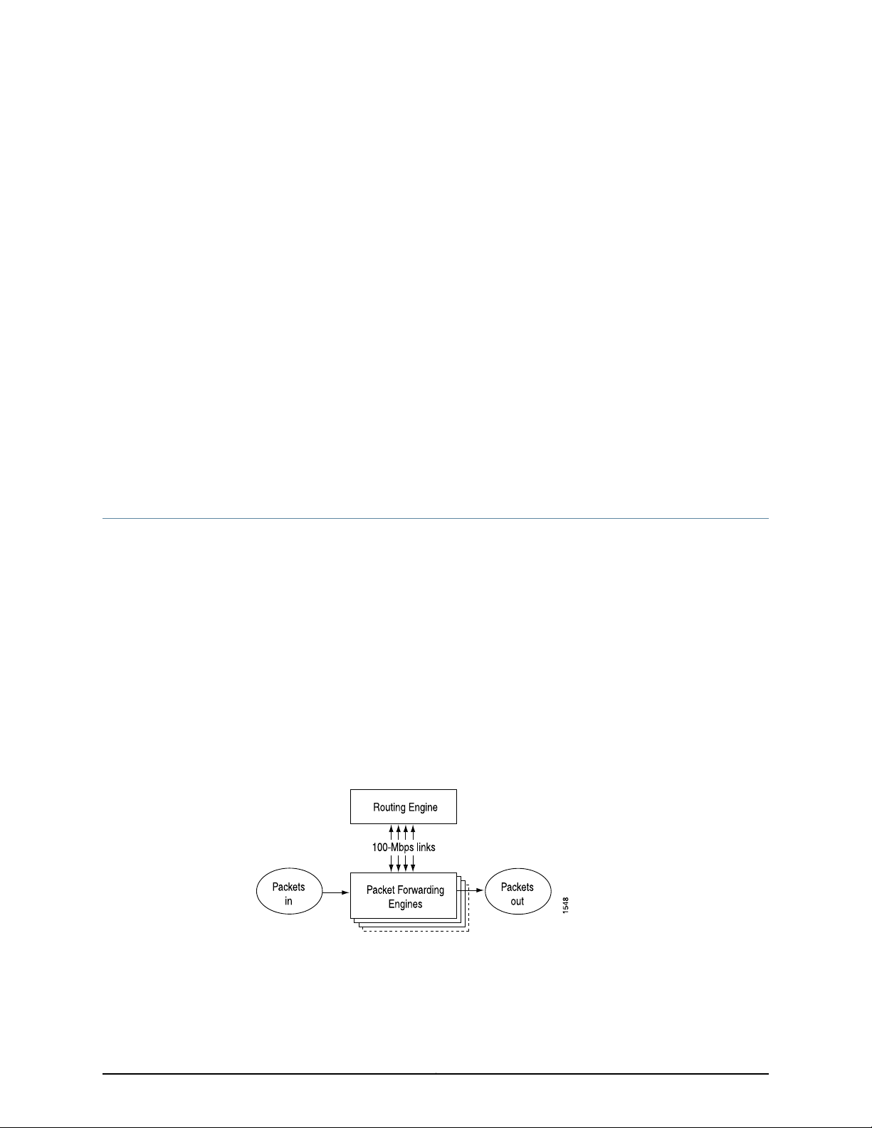
CHAPTER 2
Overview of the T640 Router System
Architecture
•
T640 System Architecture Description on page 7
•
T640 Routing Engine Functions on page 8
•
T640 Packet Forwarding Engine Architecture on page 9
•
Data Flow Through the T640 Router on page 10
T640 System Architecture Description
The T640 Core Router has two main architectural components:
•
Routing Engine—This component provides Layer 3 routing services and network
management.
•
PacketForwardingEngines—Thesehigh-performance,ASIC-basedcomponents provide
Layer 2 and Layer 3 packet switching, route lookups, and packet forwarding.
Related
Documentation
The Routing Engine and the Packet Forwarding Engines perform their primary tasks
independently, although theyconstantly communicate through multiple 100-Mbps links.
This arrangement streamlines forwarding and routing control and runs Internet-scale
backbone networks at high speeds. Figure 1 on page 7 shows the relationship between
the Routing Engine and the Packet Forwarding Engines.
Figure 1: Router Architecture
T640 Chassis Description on page 13•
• Safety Requirements, Warnings, and Guidelines for Installing the T640 Router on
page 85
7Copyright © 2010, Juniper Networks, Inc.
Page 38

T640 Core Router Hardware Guide
T640 Routing Engine Functions
The Routing Engine handles all routing protocol processes, as well as the software
processes that control the router's interfaces, the chassis components, system
management, and user access to the router. These routing and software processes run
on topof a kernel that interacts withthe Packet Forwarding Engine. For more information
about the processes, see the Junos OS System Basics and Services Command Reference.
The Routing Engine includes the functions and features:
•
Processing of routing protocol packets—The Routing Engine handles all packets that
concern routing protocols, freeing thePacketForwarding Engineto handle only packets
that represent Internet traffic.
•
Softwaremodularity—Becauseeach software process is devoted to a different function
and uses a separate process space, the failure of one process has little or no effect on
the others.
•
In-depth Internet functionality—Each routingprotocolis implemented with a complete
set ofInternet featuresand provides fullflexibility for advertising, filtering, and modifying
routes. Routing policies are set according to route parameters (for example, prefix,
prefix lengths, and BGP attributes).
•
Scalability—The Junos routing tables have been designed to hold all the routes in
current networks with ample capacity for expansion. Additionally, the Junos OS can
efficiently support large numbers of interfaces and virtual circuits.
•
Management interface—Different levels of system management tools are provided,
including the Junos OS command-line interface (CLI), the Junos XML management
protocol, the craft interface, and SNMP.
•
Storage and change management—Configuration files,system images, andmicrocode
can be held and maintained in primary and secondary storage systems, permitting
local or remote upgrades.
•
Monitoring efficiency and flexibility—The router supports functions such as alarm
handling and packet counting on every port, without degrading packet-forwarding
performance.
The Routing Engine constructs and maintains one or more routing tables (see Figure 2
on page 9). From the routing tables, the Routing Engine derives a table of active routes,
called the forwarding table, which is then copied into the Packet Forwarding Engine. The
design of the ASICs allow the forwarding table in the Packet Forwarding Engine to be
updated without interrupting forwarding performance.
Copyright © 2010, Juniper Networks, Inc.8
Page 39
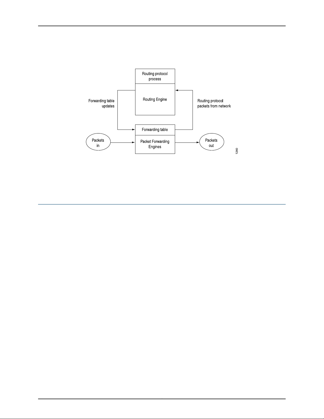
Chapter 2: Overview of the T640 Router System Architecture
Figure 2: Control Packet Handling for Routing and Forwarding Table
Updates
Related
Documentation
Replacing a T640 Routing Engine on page 206•
• T640 Routing Engine Description on page 32
• Maintaining the T640 Routing Engines on page 148
T640 Packet Forwarding Engine Architecture
The Packet Forwarding Engines provide the Layer 2 and Layer 3 packet switching,
forwarding, and route lookup functions. In a maximum configuration with eight Type 3
FPCs installed, the Packet Forwarding Engines can forward up to 640 million packets
per second (Mpps) for all packet sizes. The maximum aggregate throughput rate for the
T640 router is 320 Gbps (full duplex). The Packet Forwarding Engines are implemented
in ASICs that are physically located on the FPCs and the PICs.
Each Packet Forwarding Engine consists of the following components (see Figure 3 on
page 10):
•
Layer 2/Layer 3 Packet Processing ASIC, which performs Layer 2 and Layer 3
encapsulation and de-encapsulation, and manages the division and reassembly of
packets within the T640 router.
•
Queuing and Memory Interface ASICs, which manage the buffering of data cells in
memory and the queueing of notifications.
•
T-series Internet Processor, which provides the route lookup function.
Related
Documentation
•
Switch Interface ASICs, which extract the route lookup key and manage the flow of
data cells across the switch fabric.
•
Media-specific ASICs on the PICs that perform control functions tailored to the PIC
media types.
T640 Chassis Description on page 13•
• T640 Physical Specifications on page 341
9Copyright © 2010, Juniper Networks, Inc.
Page 40
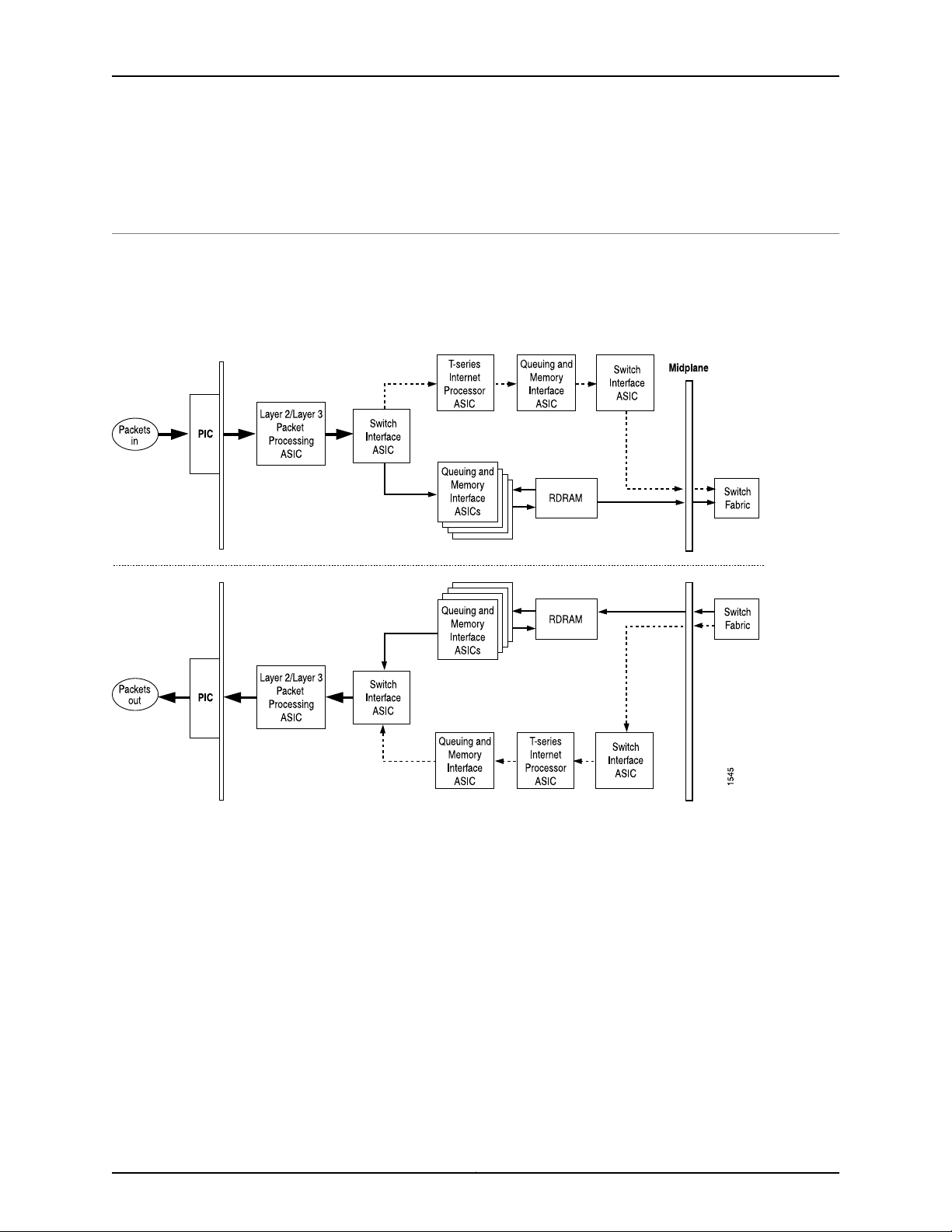
T640 Core Router Hardware Guide
• Replacing T640 Packet Forwarding Engine Components on page 219
Data Flow Through the T640 Router
To ensure the efficient movement of data through the T640 Core Router, the router is
designed so that ASICs on the hardware components handle the forwarding of data.
Data flows through the T640 router in the following sequence (see Figure 3 on page 10):
Figure 3: Data Flow Through the T640 Router
1. Packets arrive at an incoming PIC interface.
2. The PIC passes the packets to the FPC, where the Layer 2/Layer 3 Packet Processing
ASIC performs Layer 2 and Layer 3 parsing and divides the packets into 64-byte cells.
3. The Switch Interface ASIC extracts the route lookup key, places it in a notification and
passes the notification to the T-series Internet Processor. The Switch Interface ASIC
also passes the data cells to the Queuing and Memory Interface ASICs for buffering.
4. The Queuing and Memory InterfaceASICs pass the data cellsto memoryfor buffering.
5. The T-series Internet Processorperforms theroute lookup and forwards the notification
to the Queuing and Memory Interface ASIC.
6. TheQueuing andMemory Interface ASIC sends the notification to theSwitch Interface
ASIC facing the switch fabric, unless the destination is onthe samePacket Forwarding
Engine. In this case, the notification is sent back to the Switch Interface ASIC facing
Copyright © 2010, Juniper Networks, Inc.10
Page 41

Chapter 2: Overview of the T640 Router System Architecture
the outgoing ports, and the packets are sent to the outgoing port without passing
through the switch fabric (see Step 13).
7. The Switch Interface ASIC sends bandwidth requests through the switch fabric to the
destination port. The Switch Interface ASIC also issues read requests to the Queuing
and Memory Interface ASIC to begin reading data cells out of memory.
8. The destination Switch Interface ASIC sends bandwidth grants through the switch
fabric to the originating Switch Interface ASIC.
9. On receipt of each bandwidth grant, the originating Switch Interface ASIC sends a
cell through the switch fabric to the destination Packet Forwarding Engine.
10. The destination Switch Interface ASIC receives cells from the switch fabric. It extracts
the route lookup key from each cell, places it in a notification, and forwards the
notification to the T-series Internet Processor.
11. The T-series Internet Processor performs the route lookup, and forwards the
notification to the Queuing and Memory Interface ASIC.
12. The Queuing and Memory Interface ASIC forwardsthe notification, including next-hop
information, to the Switch Interface ASIC.
Related
Documentation
13. The Switch Interface ASIC sends read requests to the Queuing and Memory Interface
ASIC to read the data cells out of memory, and passes the cells to the Layer 2/Layer
3 Packet Processing ASIC.
14. The Layer 2/Layer 3 Packet Processing ASIC reassembles the data cells into packets,
adds Layer 2 encapsulation, and sends the packets to the outgoing PIC interface.
15. The outgoing PIC sends the packets out into the network.
• T640 Chassis Description on page 13
• T640 Physical Specifications on page 341
• Replacing T640 Packet Forwarding Engine Components on page 219
11Copyright © 2010, Juniper Networks, Inc.
Page 42

T640 Core Router Hardware Guide
Copyright © 2010, Juniper Networks, Inc.12
Page 43

CHAPTER 3
T640 Router Hardware Component
Overview
These topics provide an overview of the T640 router hardware components:
•
T640 Chassis Description on page 13
•
T640 Midplane Description on page 16
•
T640 Flexible PIC Concentrators (FPCs) Overview on page 18
•
T640 PIC Description on page 29
•
T640 Switch Interface Boards (SIBs) Description on page 30
•
T640 Host Subsystem Overview on page 32
•
T640 SONET Clock Generators (SCGs) Overview on page 40
•
T640 Craft Interface Overview on page 41
•
T640 Connector Interface Panel (CIP) Description on page 46
•
T640 Routing Engine Ports on page 47
•
T640 Alarm Relay Contacts on page 48
•
T640 Power System Overview on page 48
•
T640 Cooling System Description on page 61
•
T640 Cable Management System Description on page 62
T640 Chassis Description
The T640 Core Router chassis is a rigid sheet metal structure that houses all the other
router components (see Figure 4 on page 15 and Figure 5 on page 16). The chassis
measures 37.45 in. (95.1 cm) high, 31 in. (78.7 cm) deep, and 17.43 in. (44.3 cm) wide. For
physical specifications, see “T640 Physical Specifications” on page 341. The chassis can
be installed into many types of racks or cabinets. For more information. see “T640 Rack
Requirements” on page 66.
The chassis includes the following features (see Figure 4 on page 15 and Figure 5 on
page 16):
•
One pairof metal flanges for front-mounting ormounting ina four-post rack or cabinet.
•
One pair of metal brackets for center-mounting.
13Copyright © 2010, Juniper Networks, Inc.
Page 44

T640 Core Router Hardware Guide
•
•
Installation handles on each side to facilitate positioning the router in the rack. Do not
use the handles to lift the router.
Two electrostatic discharge (ESD) points (banana plug receptacles), one front and
one rear.
CAUTION: Before removing or installing components of a router, attach
an ESD strap to an ESD point and place the other end of the strap around
your bare wrist. Failure to use an ESD strap could result in damage to the
router.
WARNING: The router must be connected to earth ground during normal
operation.
Copyright © 2010, Juniper Networks, Inc.14
Page 45
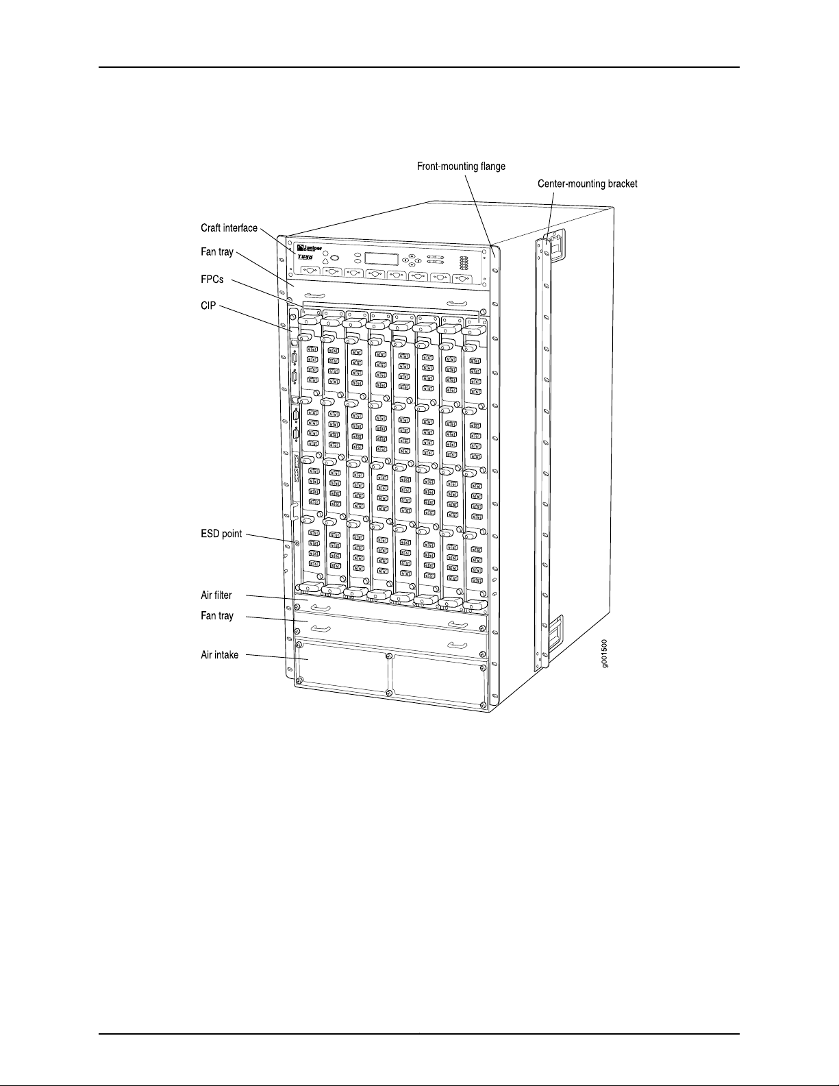
Chapter 3: T640 Router Hardware Component Overview
Figure 4: Front View of T640 Chassis
15Copyright © 2010, Juniper Networks, Inc.
Page 46
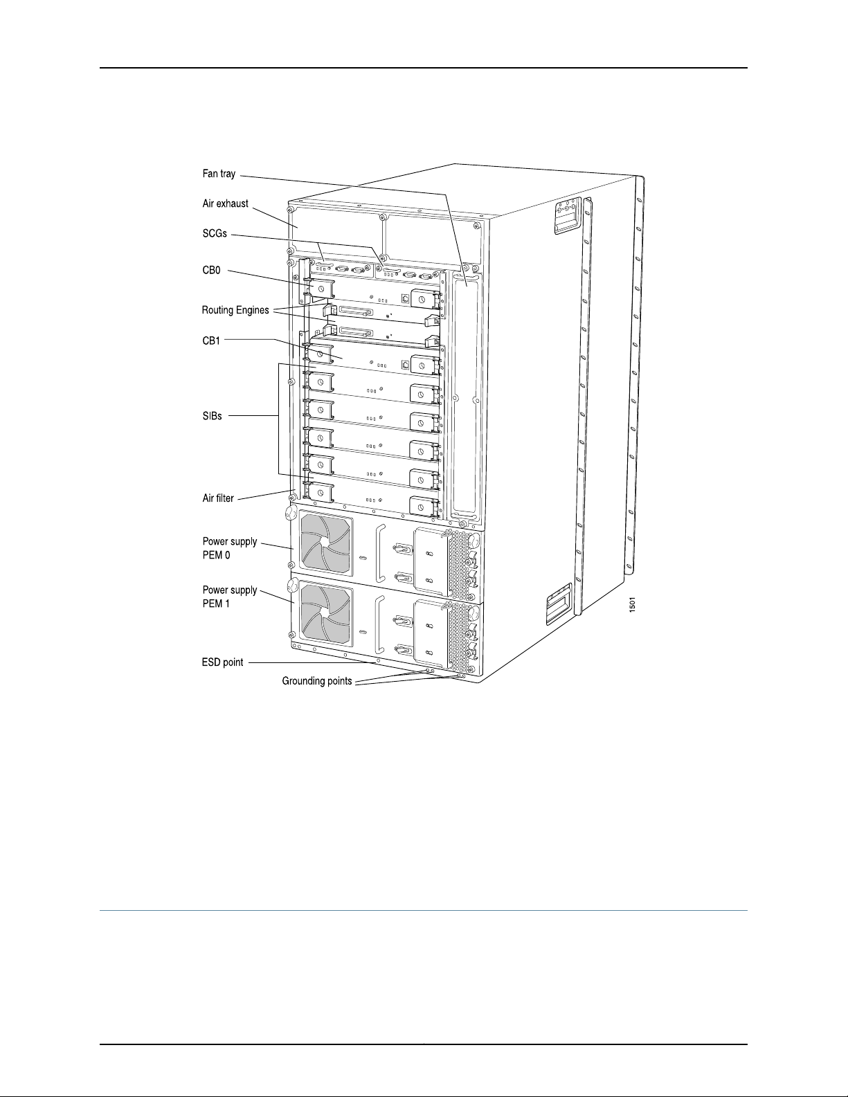
T640 Core Router Hardware Guide
Figure 5: Rear View of T640 Chassis
For chassis serial number information , see “Locating T640 Component Serial Numbers
Using the CLI” on page 369.
Related
Documentation
Safety Requirements, Warnings, and Guidelines for Installing the T640 Router on
•
page 85
• T640 Physical Specifications on page 341
• T640 Chassis Grounding Cable and Lug Specifications on page 345
• T640 Chassis Lifting Guidelines on page 310
T640 Midplane Description
The T640 Core Router midplane is located in the center of the chassis and forms the
rear of the FPC card cage (see Figure 6 on page 17). The FPCs install into the midplane
from the front of the chassis, and the SIBs, Routing Engines, control boards, and SCGs
Copyright © 2010, Juniper Networks, Inc.16
Page 47
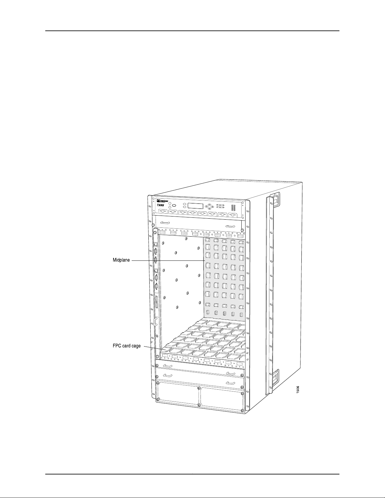
Chapter 3: T640 Router Hardware Component Overview
install into the midplane from the rear of the chassis. The power supplies and cooling
system components also connect to the midplane.
The midplane performs the following major functions:
•
Data path—Data packets are transferred across the midplane from the Packet
Forwarding Engine on the originating FPC to the SIBs, and from the SIBs across the
midplane to the Packet Forwarding Engine on the destination FPC.
•
Power distribution—The router power supplies are connected to the midplane, which
distributes power to all the router components.
•
Signal path—The midplane providesthe signalpath to theFPCs, SIBs,Routing Engines,
and T-CBs, and other system components for monitoring and control of the system.
Figure 6: T640 Midplane
For chassis serial number information , see “Locating T640 Component Serial Numbers
Using the CLI” on page 369.
17Copyright © 2010, Juniper Networks, Inc.
Page 48

T640 Core Router Hardware Guide
Related
Documentation
T640 Router Description on page 3•
• Safety Requirements, Warnings, and Guidelines for Installing the T640 Router on
page 85
• T640 Physical Specifications on page 341
T640 Flexible PIC Concentrators (FPCs) Overview
•
T640 FPC Description on page 18
•
T640 FPCs Supported on page 28
T640 FPC Description
Up to eight Flexible PIC Concentrators (FPCs) install vertically in the front of the T640
Core Router (see Figure 7 on page 19). The FPC slots are numbered left to right from
FPC0 to FPC7. An FPC can be installed into any FPC slot on the router, regardless of which
PICs it contains.
If a slot is not occupied by an FPC, an FPC blank panel must be installed to shield the
empty slot and to allow cooling air to circulate properly through the router.
Each FPC contains oneor two Packet ForwardingEngines. ThePacketForwarding Engines
receive incoming packets from the PICs installed on the FPC and forward them through
the switch planes to the appropriate destination port. Each FPC contains data memory
that is managed by the Queuing and Memory Interface ASICs.
FPCs are hot-removable andhot-insertable, as describedin “T640 Router FRU Overview”
on page 4. When you install an FPC into a functioning router, the Routing Engine
downloads the FPC software, the FPC runs its diagnostics, and the PICs housed on the
FPC are enabled. Forwarding continues uninterrupted during this process. For FPC
replacement instructions, see “Replacing a T640 FPC” on page 219.
Each FPC consists of the following components:
•
FPC card carrier.
•
One ortwo Packet ForwardingEngines, consisting ofLayer2/Layer 3 Packet Processing
ASICs, Switch Interface ASICs, T-series Internet Processor ASICs, and a Memory
Mezzanine Board (MMB) which includes the Queuing and Memory Interface ASICs.
Each Type 1, Type 2, and Type 4 FPChas one Packet Forwarding Engine, and each Type
3 FPC has two Packet Forwarding Engines.
•
ProcessorMezzanine Board(PMB), which includes a 300-MHz CPU,system controller,
256 MB of SDRAM, and two Fast Ethernet interfaces.
•
Two LEDs, located on the craft interface above the FPC, that display the status of the
FPC. For more information about the FPC LEDs, see “T640 Craft Interface FPC LEDs
and Online/Offline Buttons” on page 45.
•
FPC online/offline button, located on the craft interface above the FPC.
Copyright © 2010, Juniper Networks, Inc.18
Page 49
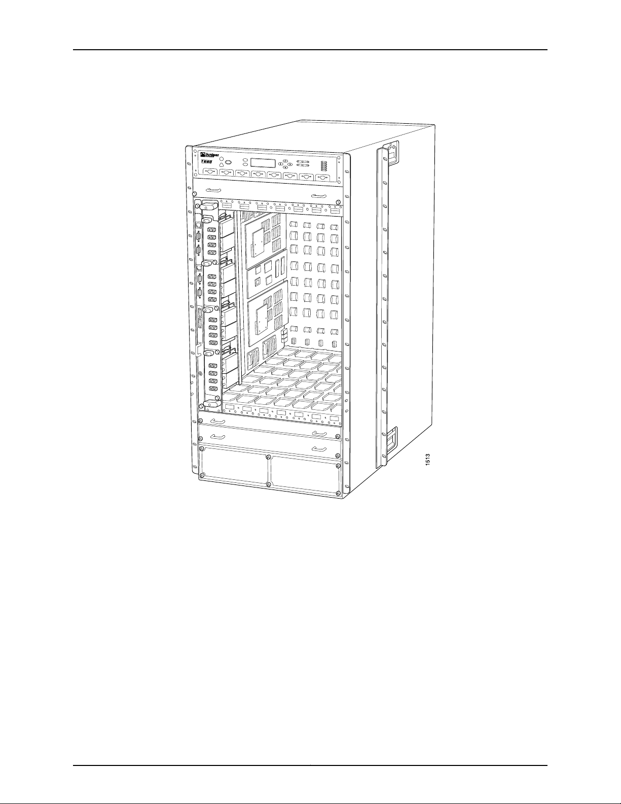
Chapter 3: T640 Router Hardware Component Overview
Figure 7: FPC Installed in a T640 Chassis
FPC Terminology
Regardless of whether you are holding an FPC vertically or horizontally, this document
uses the same terms for all four edges of the FPC (see Figure 8 on page 20):
•
Faceplate—Edge of the FPC that has slots into which you insert the PICs
•
Connectoredge—Edge opposite the faceplate;this edgehas the connectorsthat attach
to the midplane
•
Top edge—Edge at the top of the FPC when it is vertical
•
Bottom edge—Edge at the bottom of the FPC when it is vertical
19Copyright © 2010, Juniper Networks, Inc.
Page 50
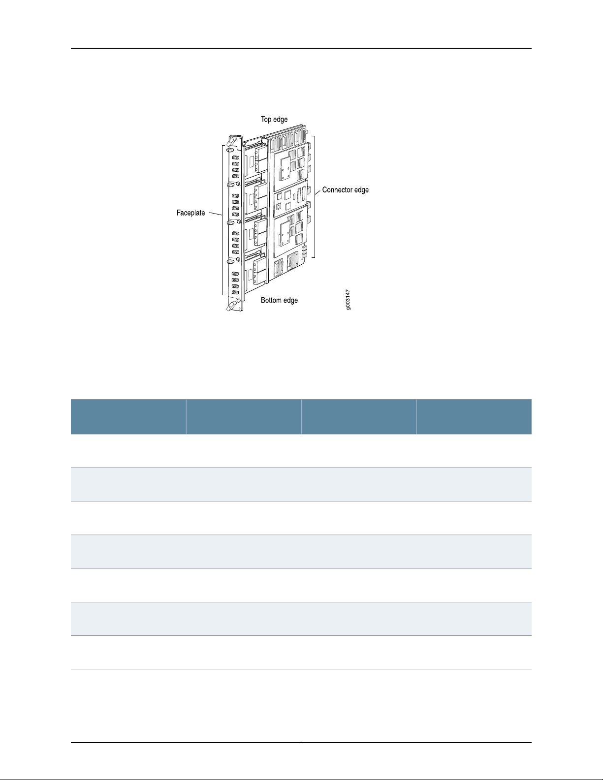
T640 Core Router Hardware Guide
Figure 8: FPC Edges
Identifying T640 FPCs
Check the label on the faceplate to identify the FPC. For FPCs without a label on the
faceplate, check the location of a PIC's offline button and how the PIC is secured to the
FPC. See Table 4 on page 20.
Table 4: Identifying the FPCs Supported by the T640 Router
Location of PIC Offline
ButtonLabelon theFPC FaceplateFPC
E FPC1Enhanced FPC1
of the PIC
E-II FPC1Enhanced II FPC1
of the PIC
T640-FPC1-ESEnhanced Scaling FPC1
of the PIC
NoneFPC2
the faceplate of each PIC
E FPC2Enhanced FPC2
the faceplate of each PIC
E-II FPC2Enhanced II FPC2
the faceplate of each PIC
Methodof Securingthe PIC
to the FPC
Two captive screwsSlightly beneath thefaceplate
Two captive screwsSlightly beneath thefaceplate
Two captive screwsSlightly beneath thefaceplate
Two captive screwsInside an opening directly on
Two captive screwsInside an opening directly on
Two captive screwsInside an opening directly on
T640-FPC2-ESEnhanced Scaling FPC2
the faceplate of each PIC
Two captive screwsInside an opening directly on
Copyright © 2010, Juniper Networks, Inc.20
Page 51

Chapter 3: T640 Router Hardware Component Overview
Table 4: Identifying the FPCs Supported by the T640 Router (continued)
FPC4-1P
Location of PIC Offline
ButtonLabelon theFPC FaceplateFPC
NoneFPC3
E FPC3Enhanced FPC3
E-11 FPC3Enhanced II FPC3
T640-FPC3-ESEnhanced Scaling FPC3
FPC4T640 EnhancedScaling FPC4
T640-FPC4–1P-EST640 Enhanced Scaling
Inside an opening directly on
the faceplate of each PIC
Inside an opening directly on
the faceplate of each PIC
Inside an opening directly on
the faceplate of each PIC
Inside an opening directly on
the faceplate of each PIC
Inside an opening directly on
the faceplate of each PIC
Inside an opening directly on
the faceplate of each PIC
Methodof Securingthe PIC
to the FPC
Plastic ejector handle at the
top of the PIC faceplate;
captive screw at the bottom
of the PIC faceplate
Two plastic ejector handles
at the top and bottom of the
PIC faceplate
Two plastic ejector handles
at the top and bottom of the
PIC faceplate
Two plastic ejector handles
at the top and bottom of the
PIC faceplate
Two plastic ejector handles
at the top and bottom of the
PIC faceplate
Two plastic ejector handles
at the top and bottom of the
PIC faceplate
21Copyright © 2010, Juniper Networks, Inc.
Page 52
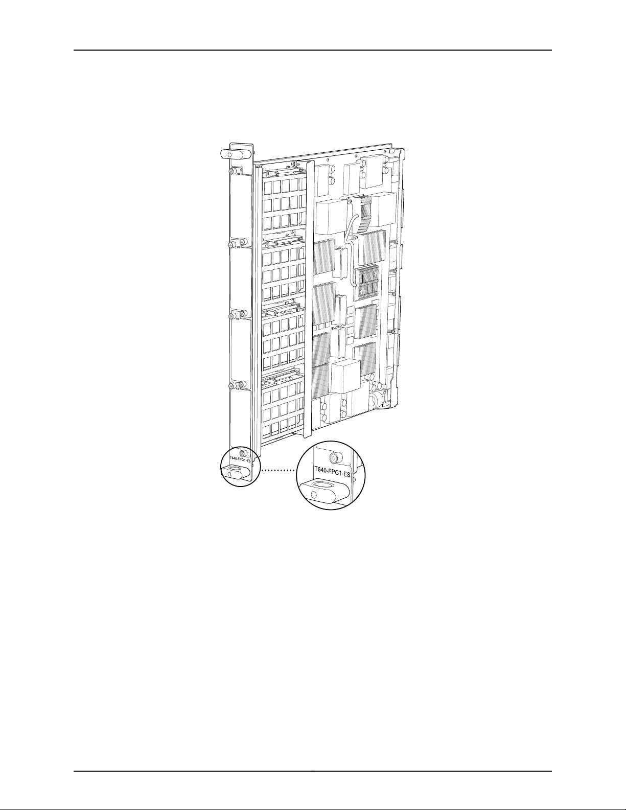
g004427
T640 Core Router Hardware Guide
The T640 router supports the Enhanced Scaling FPC1, as shown in Figure 9 on page 22.
Figure 9: Enhanced Scaling FPC1 Supported by the T640 Router
The T640 routersupports thestandard FPC2 andFPC3, as shown in Figure 10 on page 23.
Copyright © 2010, Juniper Networks, Inc.22
Page 53

g003925
FPC2
FPC3
Chapter 3: T640 Router Hardware Component Overview
Figure 10: Standard FPC2 and FPC3 Supported by the T640 Router
23Copyright © 2010, Juniper Networks, Inc.
Page 54
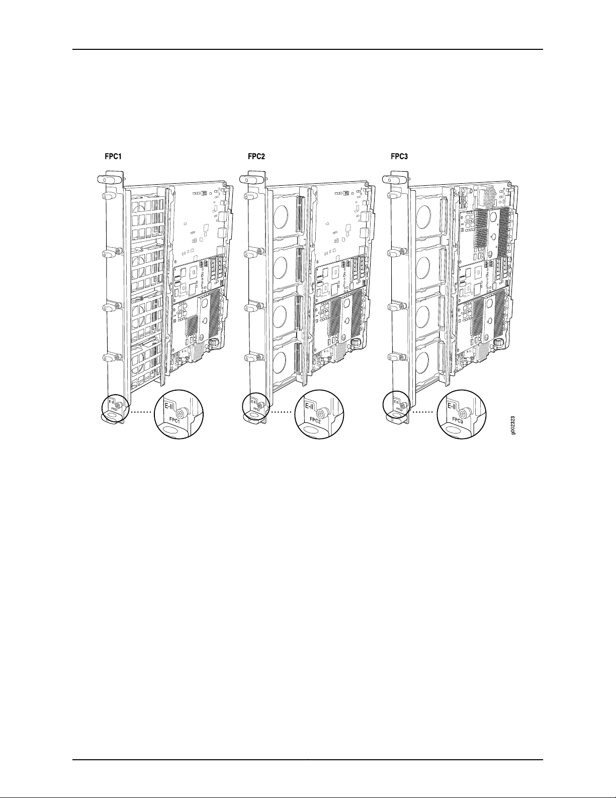
T640 Core Router Hardware Guide
The T640 router supports the Enhanced II FPC1, FPC2 and FPC3, as shown in Figure 11
on page 24.
Figure 11: Enhanced II FPC1, FPC2,and FPC3 Supported by the T640 Router
Copyright © 2010, Juniper Networks, Inc.24
Page 55
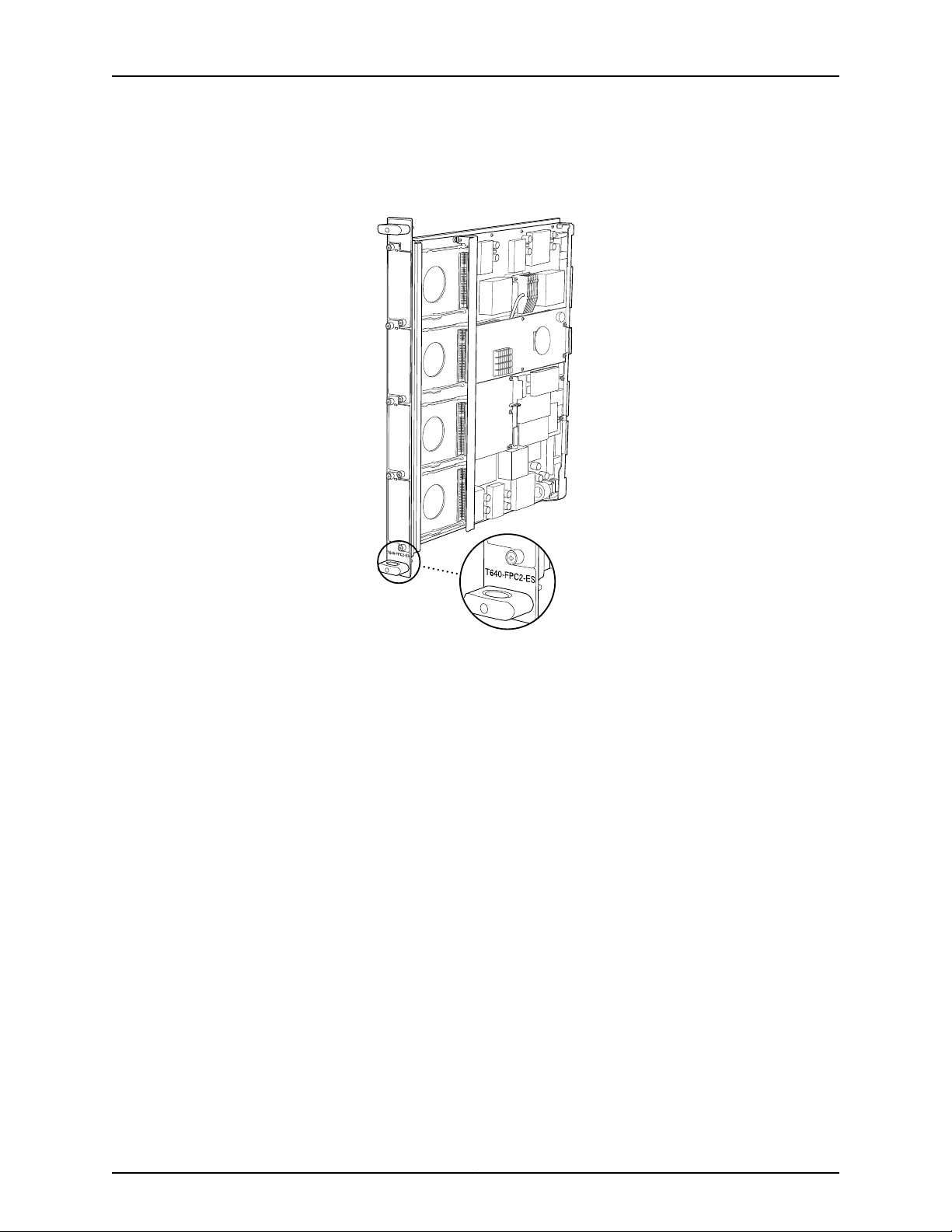
g004433
Chapter 3: T640 Router Hardware Component Overview
The T640 router supports the Enhanced Scaling FPC2, as shown in Figure 12 on page 25.
Figure 12: Enhanced Scaling FPC2 Supported by the T640 Router
The T640 router supports the Enhanced Scaling FPC3, as shown in Figure 13 on page 26.
25Copyright © 2010, Juniper Networks, Inc.
Page 56
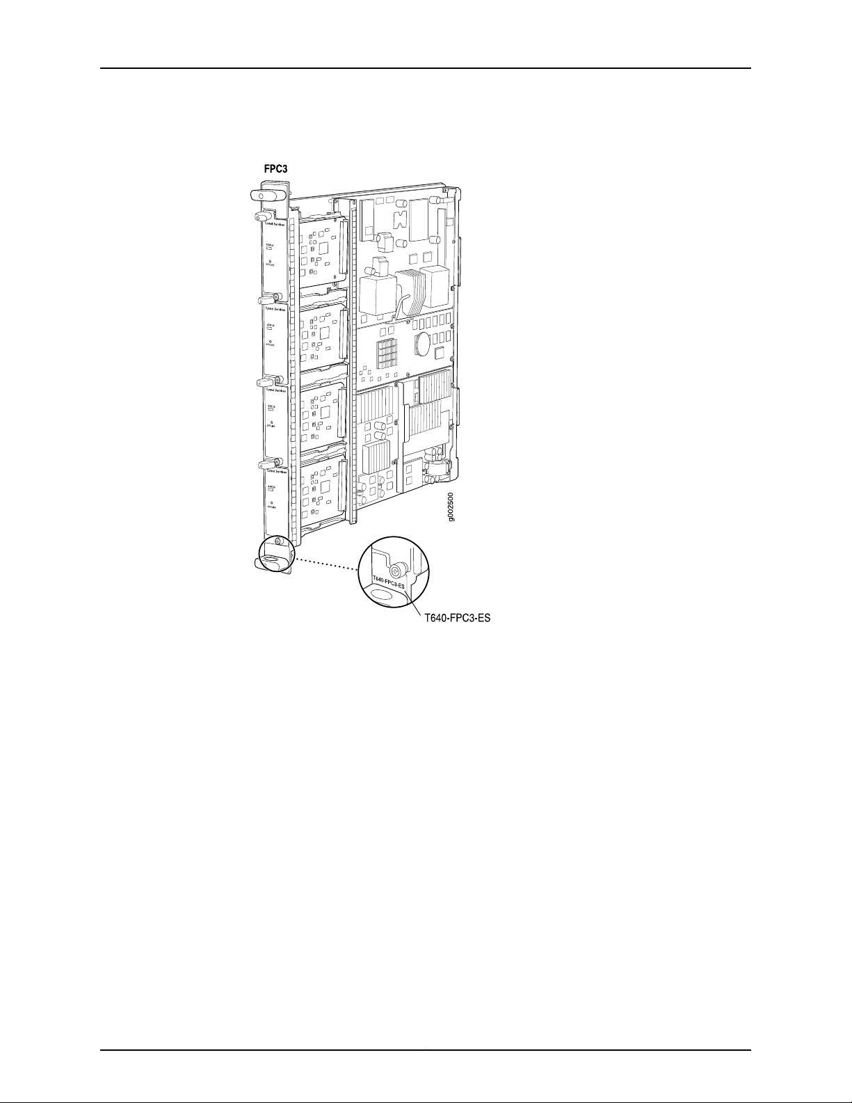
T640 Core Router Hardware Guide
Figure 13: Enhanced Scaling FPC3 Supported by the T640 Router
Copyright © 2010, Juniper Networks, Inc.26
Page 57
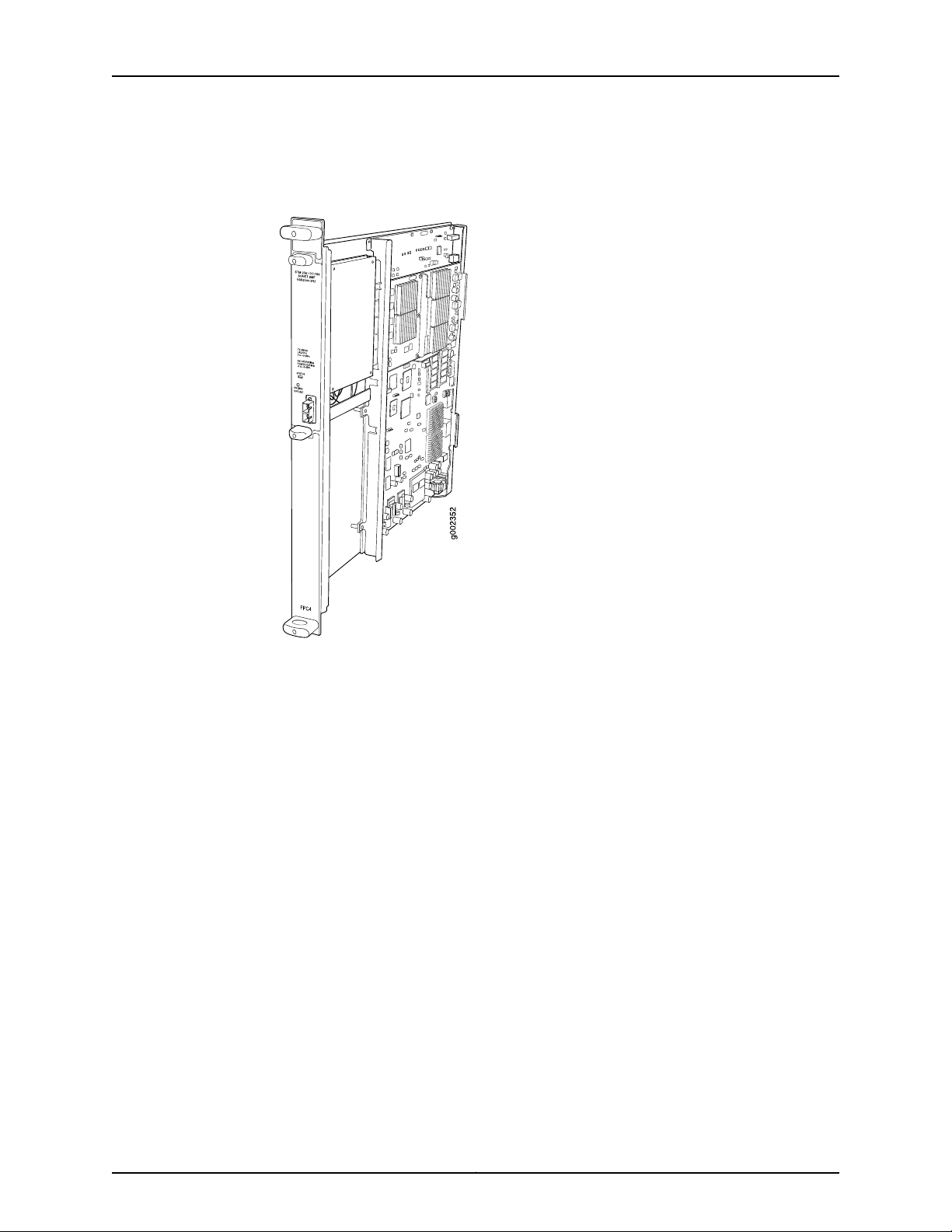
Chapter 3: T640 Router Hardware Component Overview
The T640 router supports the Enhanced Scaling FPC4, as shown in Figure 14 on page 27.
Figure 14: Enhanced Scaling FPC4 Supported by the T640 Router
27Copyright © 2010, Juniper Networks, Inc.
Page 58
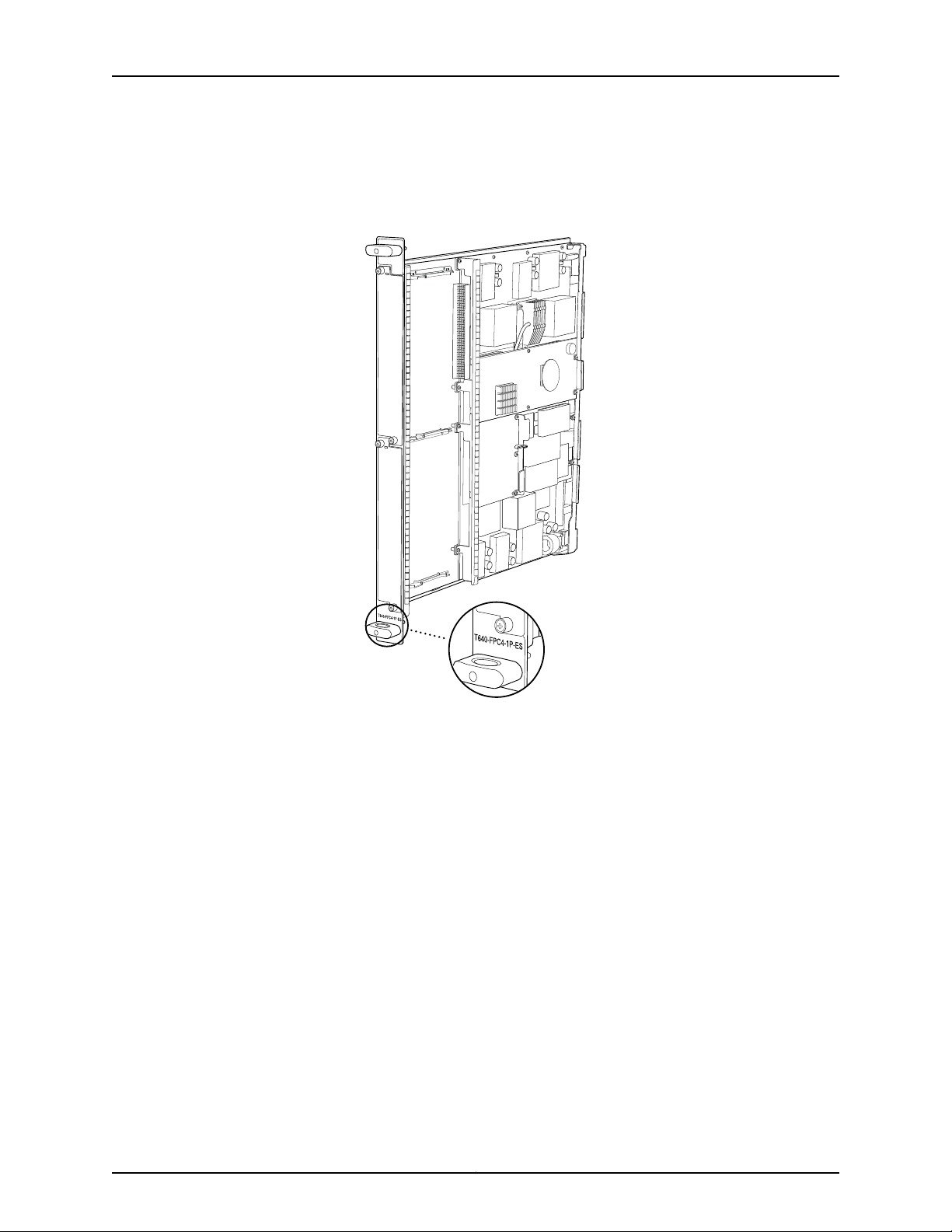
g004434
T640 Core Router Hardware Guide
The T640 router supports the T640 Enhanced Scaling FPC4-1P, as shown in Figure 15
on page 28.
Figure 15: T640 EnhancedScaling FPC4-1P Supportedby the T640 Router
Related
Documentation
T640 FPCs Supported
T640 FPCs Supported on page 28•
• Maintaining T640 FPCs on page 151
• Troubleshooting the T640 FPCs on page 169
T640 routers support the FPCs listed in Table 5 on page 29. You can install any
combination of the following FPCs.
Copyright © 2010, Juniper Networks, Inc.28
Page 59

Table 5: FPCs Supported by the T640 Router
FPC Model
NumberFPC NameFPC Type
FPC1
FPC2
Chapter 3: T640 Router Hardware Component Overview
Maximum
Number of PICs
Maximum
Throughput per
FPC
First Junos OS
Release
6.34 Gbps4T640-FPC1-EEnhanced FPC11
7.44 Gbps4T640-FPC1-E2Enhanced II FPC1
9.44 Gbps4T640-FPC1-ESEnhanced Scaling
5.316 Gbps4T640-FPC2FPC22
6.316 Gbps4T640-FPC2-EEnhanced FPC2
7.416 Gbps4T640-FPC2-E2Enhanced II FPC2
9.516 Gbps4T640-FPC2-ESEnhanced Scaling
FPC3
4
FPC4
FPC4-1P
Related
Documentation
• T640 Craft Interface FPC LEDs and Online/Offline Buttons on page 45
• Troubleshooting the T640 FPCs on page 169
T640 PIC Description
PICs provide the physical connection to various network media types,receiving incoming
packets from the network and transmitting outgoing packets to the network. During this
process, each PIC performs framing and line-speed signaling for its media type. Before
transmitting outgoing data packets, the PICs encapsulate the packets received from the
FPCs. Each PIC is equipped with an ASIC that performs control functions specific to the
media type of that PIC.
5.340 Gbps4T640-FPC3FPC33
6.340 Gbps4T640-FPC3-EEnhanced FPC3
7.440 Gbps4T640-FPC3-E2Enhanced II FPC3
9.040 Gbps4T640-FPC3-ESEnhanced Scaling
7.550 Gbps1T640-FPC4-ESEnhanced Scaling
9.550 Gbps1T640-FPC4-1P-ESEnhanced Scaling
Maintaining T640 FPCs on page 151•
29Copyright © 2010, Juniper Networks, Inc.
Page 60

T640 Core Router Hardware Guide
PICs are hot-removable and hot-insertable. You can install up to four PICs in the slots
of each Type 1, 2, and 3 FPC, and one PIC in a Type 4 FPC. Type 1 and Type 2 PICs have
captive screws at theirupper and lower corners. Type 3 PICs have an upper ejector handle
and a lower captive screw. Type 4 PICs have an upper ejector handle and a lower ejector
handle.
The router supportsvarious PICs,including ATM, Channelized, GigabitEthernet, IPServices,
and SONET/SDH interfaces. Blank PICs resemble other PICs but do not provide any
physical connection or activity. When a slot is not occupied by a PIC, you must insert a
blank PIC to fill the empty slot and ensure proper cooling of the system.
Related
Documentation
T640 PICs Supported•
• T640 End-of-Life PICs Supported
T640 Switch Interface Boards (SIBs) Description
The Switch Interface Boards (SIBs) provide the switching function to the destination
FPC (see Figure 16 on page 31).
The SIBs create the switch fabric for the router, providing up to a total of 640 million
packets per second (Mpps) of forwarding. Five SIBs are installed in the router. The SIBs
are located at the center rear of the chassis in the slots labeled SIB0 through SIB4 (top
to bottom).
SIBs are hot-insertable and hot-removable.
Each Type 1 FPC and Type 2 FPC has a dedicated ASIC with five high-speed links that
connect to the SIBs (one link per SIB). Each Type 3 FPC has two dedicated ASICs, and
each ASIC has five high-speed links that connect to the SIBs (a total of 10 links). Each
Type 4 FPC has one dedicated ASIC with ten high-speed links that connect to the SIBs
(two links per SIB).One of the five SIBs—usually SIB4—acts as abackup tothe remaining
four SIBs. If a SIB fails, the backup SIB becomes active and traffic forwarding continues
without any degradation. When the failed SIB is replaced, it becomes the new backup.
The T640 router supports these types of SIBs:
•
Standard SIB
•
Standard SIB version B (supported in Junos OS Release 7.3 and later) is required to
support the Enhanced Scaling FPCs in a standalone T640 router. If you use one or
more Enhanced Scaling FPCs in a T640 router that is not part of a routing matrix, each
SIB in the router must be a SIB version B. All the SIBs in the T640 router can be either
standard SIB or SIB version B. You cannot use both on the same router at the same
time.
Copyright © 2010, Juniper Networks, Inc.30
Page 61
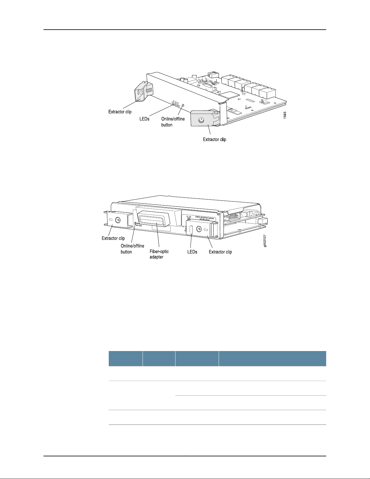
Chapter 3: T640 Router Hardware Component Overview
Figure 16: Standard SIB and Standard SIB Version B
•
The T640-SIB (supported in Junos OS Release 7.0 and later) is required to support
T640 routers connected to a TX Matrix platform); see Figure 17 on page 31. The T640
SIB supports the Enhanced Scaling FPC4 for T640 routers connected to a TX Matrix
platform.
Figure 17: T640 SIB
Each SIB consists of the following components:
•
Switch Fabric ASICs.
•
High-speed links (HSLs) to each FPC.
•
Three LEDs located on the SIB faceplate that display the status of the SIB. Table 6 on
page 31 describes the functions of the SIB LEDs. If all three LEDs are off, the SIB is not
receiving power. The OK and FAIL LEDs are replicated on the craft interface.
•
SIB online/offline button, located on the SIB faceplate.
Table 6: SIB LEDs
DescriptionStateColorLabel
SIB is in active mode.On steadilyGreenACTIVE
SIB is functioning normally.On steadilyGreenOK
SIB is starting up.Blinking
SIB has failed.On steadilyYellowFAIL
31Copyright © 2010, Juniper Networks, Inc.
Page 62

T640 Core Router Hardware Guide
Related
Documentation
Maintaining the T640 SIBs on page 158•
• Replacing a T640 SIB on page 212
• Upgrading to a T640 Standard SIB Version B on page 214
T640 Host Subsystem Overview
•
T640 Host Subsystem Description on page 32
•
T640 Routing Engine Overview on page 32
•
T640 T Series Control Boards (T-CBs) Description on page 38
•
T640 T Series Control Boards (T-CBs) LEDs on page 39
T640 Host Subsystem Description
The host subsystem provides the routing and system management functions of the
router. You can install one or two host subsystems on the router. To operate, each host
subsystem functions as a unit; the Routing Engine requires the corresponding T–CB, and
vice versa.
NOTE: We recommend that you install two host subsystems for redundant
protection. If you install only one host subsystem, we recommend that you
install it in slot RE0.
Each host subsystem has three LEDs that display its status. The host subsystem LEDs
are located on the upper right of the craft interface. For more information about the host
subsystem LEDs, see “T640 Craft Interface Host Subsystem LEDs” on page 44.
Related
Documentation
Replacing the T640 Host Subsystem Components on page 198•
• Taking the T640 Host Subsystem Offline on page 198
• Maintaining the T640 Host Subsystem on page 148
T640 Routing Engine Overview
•
T640 Routing Engine Description on page 32
•
T640 RE-600 Description on page 33
•
T640 RE-1600 Description on page 35
•
T640 RE-2000 Description on page 36
T640 Routing Engine Description
The Routing Engine is an Intel-based Peripheral Component Interconnect (PCI) platform
that runs Junos OS. Software processes that run on the Routing Engine maintain the
routing tables, manage the routing protocols used on the router, control the router
interfaces, control some chassis components, and provide the interface for system
management and user access to the router.
Copyright © 2010, Juniper Networks, Inc.32
Page 63

Chapter 3: T640 Router Hardware Component Overview
The T640 router is shipped with the Junos OS preinstalled and ready to be configured
when the T640 router is powered on. There are three copies of the software: one on a
CompactFlash card in the Routing Engine, one on a rotating hard disk in the Routing
Engine, and one on a PC Card that can be inserted into the slot in the Routing Engine
faceplate.
You can install one or two Routing Engines in the router. The Routing Engines install into
the upperrear ofthe chassisin the slots labeled RE0 and RE1.Each Routing Engine requires
a T-CB to be installed in the adjacent slot. RE0 installs below CB0, and RE1 installs above
CB1. A Routing Engine does not power up without a control board present in the adjacent
slot.
NOTE: If two Routing Engines are installed, they must both be the same
hardware model.
If two Routing Engines are installed, one functions as the master and the other acts as
the backup. If the masterRouting Engine fails or is removed, and the backup is configured
appropriately, the backup takes over as the master. If the host system is redundant, the
backup Routing Engine is hot-removable and hot-insertable, but the master Routing
Engine is hot-pluggable. A Routing Engine that is not redundant requires that you power
down the router before replacement.
Related
Documentation
NOTE: For specific information about Routing Engine components (for
example, the amount of DRAM), issue the show chassis routing-engine
command.
The ports forconnecting theRouting Engine toexternal management devices are located
on the Connector InterfacePanel (CIP).The CIP has three ports for each host subsystem:
•
10/100-Mbps Ethernet port for connecting to a management network
•
One asynchronous serial port for connecting to a console
•
One asynchronous serial port for connecting to a modem or other auxiliary device
Replacing a T640 Routing Engine on page 206•
• T640 Routing Engine Functions on page 8
• Maintaining the T640 Routing Engines on page 148
T640 RE-600 Description
The RE-600 Routing Engine boots from the storage media in this order: the PC Card (if
present), then the CompactFlash card (if present), then the hard disk.
33Copyright © 2010, Juniper Networks, Inc.
Page 64
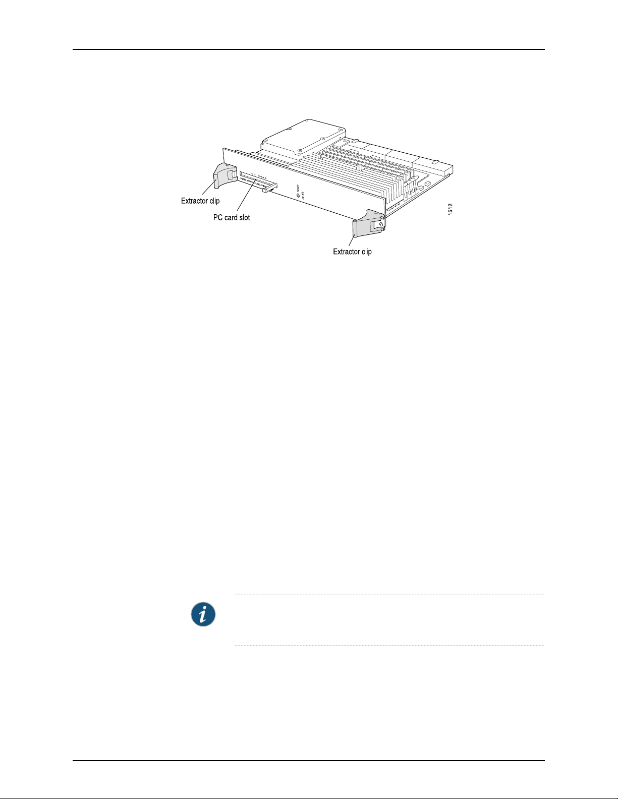
T640 Core Router Hardware Guide
Figure 18: Routing Engine 600
Each Routing Engine 600 (shown in Figure 18 on page 34) consists of the following
components:
•
CPU—Runs Junos OS to maintain the router's routing tables and routing protocols. It
has a Pentium-class processor.
•
SDRAM—Provides storage for the routing and forwarding tables and for other Routing
Engine processes.
•
CompactFlash card—Providesprimary storagefor software images, configuration files,
and microcode. The fixed CompactFlash card is inaccessible from outside the router.
•
Hard disk—Provides secondary storage for log files, memory dumps, and rebooting the
system if the CompactFlash card fails.
•
EEPROM—Stores the serial number of the Routing Engine.
•
Interfaces for management access—Provide information about Routing Engine status
to devices (console, laptop, or terminal server) connected to ports located on the
Connector Interface Panel (CIP).
The faceplate of the Routing Engine 600 contains the following:
•
One PC Card slot—Accepts a removable PC Card, which stores software images for
system upgrades.
•
Reset button—Reboots the Routing Engine when pressed.
•
HD LED—Indicates activity on the hard drive. It does not necessarily indicate
routing-related activity.
NOTE: The LEDs that report host modulestatus (including RoutingEngine
status) are on the craft interface ratherthan the Routing Engine faceplate.
•
HD LED—Table 7 on page 35 describes the functions of the LED.
Copyright © 2010, Juniper Networks, Inc.34
Page 65

Table 7: Routing Engine 600 LEDs
Chapter 3: T640 Router Hardware Component Overview
DescriptionStateColorLabel
Related
Documentation
YellowHD
blinking
Indicates activity on the hard drive.On steadily or
NOTE: The LEDs on the Routing Engine do not necessarily indicate
routing-related activity.
Replacing a T640 Routing Engine on page 206•
• T640 Routing Engine Functions on page 8
• Maintaining the T640 Routing Engines on page 148
T640 RE-1600 Description
The RE-1600 Routing Engine boots from the storage media in this order: the PC Card in
SLOT 0 (if present), then the PC Card in SLOT 1 (if present), then the CompactFlash card
(if present), then the hard disk.
Figure 19: Routing Engine 1600 (RE-1600)
Each RE-1600 (shown in Figure 19 on page 35) consists of the following components:
•
CPU—Runs Junos OS to maintain the router's routing tables and routing protocols. It
has a Pentium-class processor.
•
SDRAM—Provides storage for the routing and forwarding tables and for other Routing
Engine processes.
•
CompactFlash card—Providesprimary storagefor software images, configuration files,
and microcode. The fixed CompactFlash card is inaccessible from outside the router.
•
Hard disk—Provides secondary storage for log files, memory dumps, and rebooting the
system if the CompactFlash card fails.
35Copyright © 2010, Juniper Networks, Inc.
Page 66

T640 Core Router Hardware Guide
•
•
The faceplate of the RE-1600 contains the following:
•
•
•
Table 8: Routing Engine 1600 LEDs
EEPROM—Stores the serial number of the Routing Engine.
Interfaces for management—Provide information about Routing Engine status to
devices (console, laptop, or terminal server) connected to the Routing Engine ports
located on the CIP.
Two PC Card slots—Accept removable PC Cards, which store software images for
system upgrades.
Reset button—Reboots the Routing Engine when pressed.
LEDs—Table 8 on page 36 describes the functions of these LEDs.
DescriptionStateColorLabel
Related
Documentation
Slot LEDs 0
and 1
BlinkingRed and
green
alternately
On steadilyGreen
YellowHD
blinking
Indicates that the Routing Engine is booting
and the firmware is checking if a PC card is
installed.
Indicates that the RoutingEngine booted from
the PC Card.
Indicates activity on the hard drive.On steadily or
NOTE: The LEDs on the Routing Engine do not necessarily indicate
routing-related activity.
NOTE: The LEDs that report host modulestatus (including RoutingEngine
status) are on the craft interface ratherthan the Routing Engine faceplate.
Replacing a T640 Routing Engine on page 206•
• T640 Routing Engine Functions on page 8
• Maintaining the T640 Routing Engines on page 148
T640 RE-2000 Description
The RE-2000Routing Engine boots from thestorage media in this order: the USBdevice,
then the CompactFlash card (if present), then the hard disk, then the LAN.
Copyright © 2010, Juniper Networks, Inc.36
Page 67
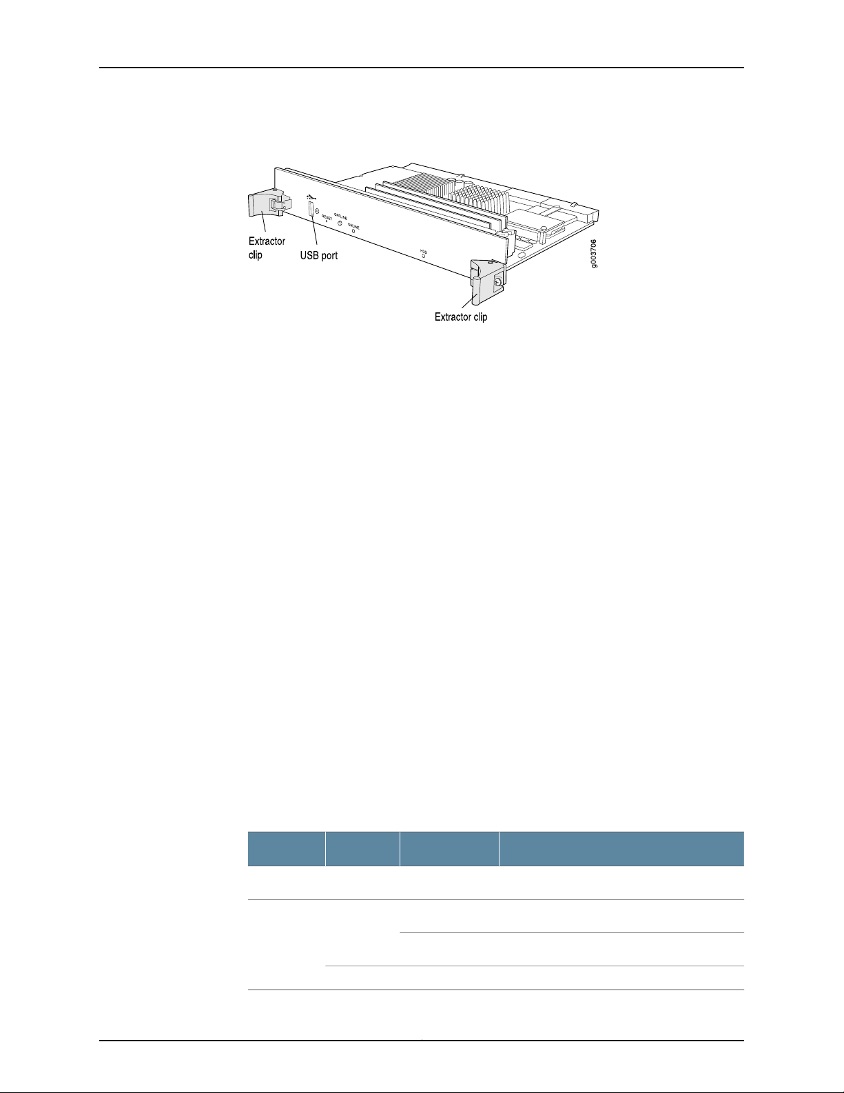
Chapter 3: T640 Router Hardware Component Overview
Figure 20: Routing Engine 2000 (RE-2000)
Each RE-2000 (shown in Figure 20 on page 37) consists of the following components:
•
CPU—Runs Junos OS to maintain the router's routing tables and routing protocols. It
has a Pentium-class processor.
•
DRAM—Provides storage for the routing and forwarding tables and for other Routing
Engine processes.
•
CompactFlash card—Providesprimary storagefor software images, configuration files,
and microcode. The fixed CompactFlash card is inaccessible from outside the router.
•
Hard disk—Provides secondary storage for log files, memory dumps, and rebooting the
system if the CompactFlash card fails.
•
EEPROM—Stores the serial number of the Routing Engine.
•
Interfaces for management access—Provide information about Routing Engine status
to devices (console, laptop, or terminal server) connected to the Routing Engine ports
located on the CIP.
The faceplate of the RE-2000 contains the following:
•
USB port—Provides a removable media interface through which you can install the
Junos OS manually. Junos OS supports USB version 1.0.
•
Reset button—Reboots the Routing Engine when pressed.
•
Offline button—Takes the Routing Engine offline when pressed.
•
Extractor clips—Control the locking system that secures the Routing Engine.
•
LEDs—Table 9 on page 37 describes the functions of these LEDs.
Table 9: Routing Engine 2000 LEDs
DescriptionStateColorLabel
Indicates disk activity for the hard disk drive.On steadilyBlueHDD
Routing Engine is functioning normally.On steadilyGreenONLINE
Routing Engine is transitioning online.Blinking
Routing Engine has failed.On steadilyRed
37Copyright © 2010, Juniper Networks, Inc.
Page 68
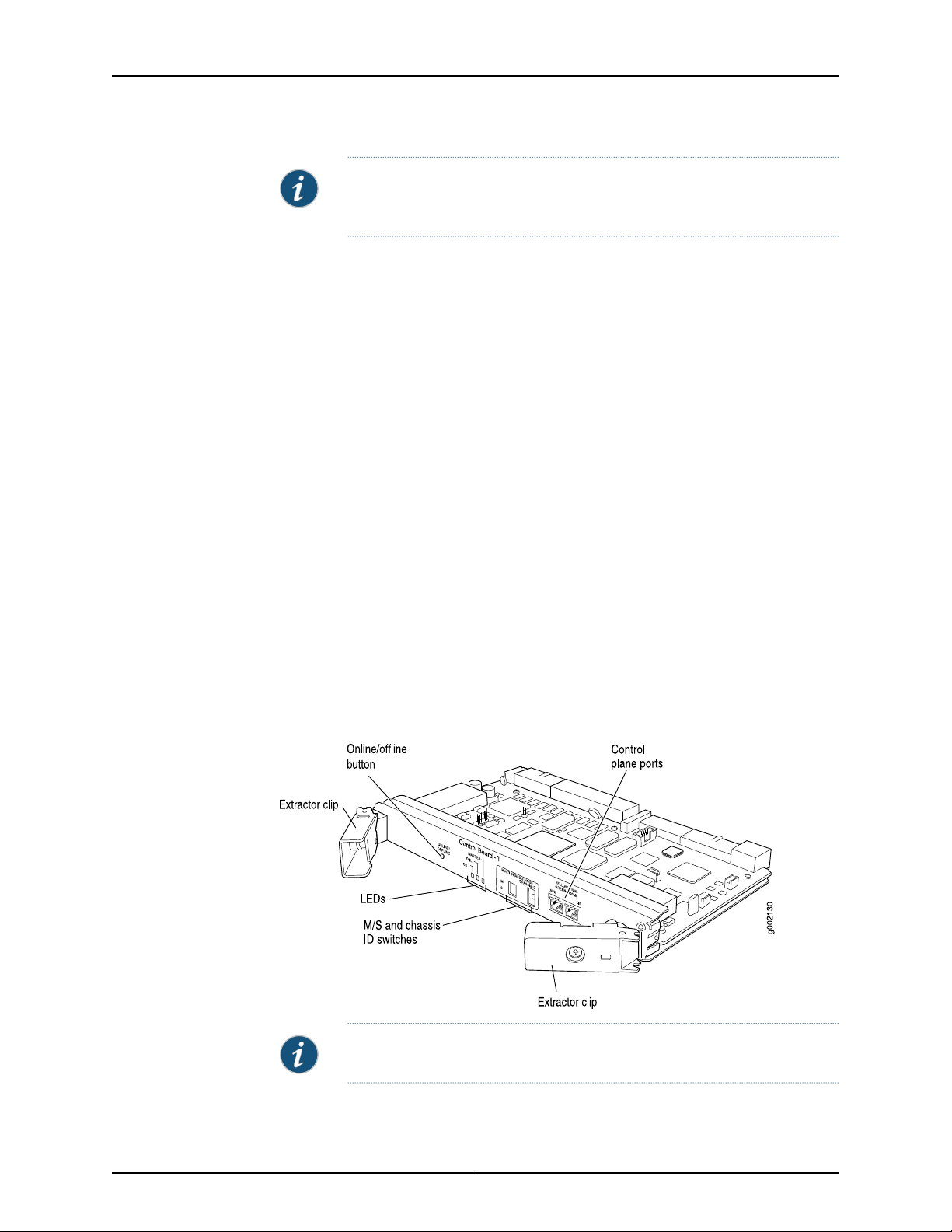
T640 Core Router Hardware Guide
NOTE: The LEDs on the Routing Engine do not necessarily indicate
routing-related activity.
Related
Documentation
Replacing a T640 Routing Engine on page 206•
• T640 Routing Engine Functions on page 8
• Maintaining the T640 Routing Engines on page 148
T640 T Series Control Boards (T-CBs) Description
This chassis supports up to two T-CBs. The Routing Engine requires an adjacent T-CB
to provide control and monitoring functions for the router (see Figure 21 on page 38).
These functions include determining Routing Engine mastership, controlling power and
reset for the other router components, monitoring and controlling fan speed, and
monitoring system status.
You can install up to two T-CBs in the router. Control boards install into the upper rear
of the chassis in the slots labeled CB0 and CB1 (referred to as CB-0 and CB-1, top to
bottom). If two T-CBs are installed, one functions as the master and the other as its
backup. If the master fails or is removed, the backup restarts and becomes the master.
Each T-CB requires a Routing Engine to be installed in the adjacent slot. CB0 installs
above RE0, and CB1 installs below RE1. T-CBs cannot function if a Routing Engine is not
present in the adjacent slot.
If the host system is redundant, the backup T-CB is hot-removable and hot-insertable,
but the master T-CB is hot-pluggable. A T-CB that is not redundant is hot-pluggable.
Figure 21: T-CB
NOTE: The T-CB requires Junos OS Release 7.0 or later.
Copyright © 2010, Juniper Networks, Inc.38
Page 69

Chapter 3: T640 Router Hardware Component Overview
Each T-CB consists of the following components:
•
100-MB Ethernet switch for intermodule communication.
•
PCI bus to the Routing Engines.
•
Processor subsystem (SPMB).
•
Three LEDs, located on the T-CB faceplate, indicate its status.
•
The T-CB online/offline button, located on the faceplate.
NOTE: When the adjacent Routing Engine is online, the online/offline
button on the T-CB faceplate is nonfunctional. For more information, see
“Taking the T640 Host Subsystem Offline” on page 198.
•
Two configuration switches, located on the faceplate:
•
For a standalone T640 router, the M/S and CHASSISID configuration switches must
always be set to S and 0.
•
For T640 routers connected to a TX Matrix platform, the M/S and CHASSIS ID
configuration switches must always be set to M and the chassis identifier (ID) of the
router. In this case, bothT-CBs must have the same chassis ID. For more information,
see the TX Matrix Router Hardware Guide.
•
Two RJ-45 ports labeled AUX and CIP on the T-CB faceplate.
•
For a standalone T640 router, these ports are not used.
•
For T640 routers connected to a TX Matrix platform, only the CIP port is used. For
more information, see the TX Matrix Router Hardware Guide.
Related
Documentation
T640 Chassis Description on page 13•
• Replacing a T640 T-CB on page 201
• Maintaining the T640 T-CBs on page 149
T640 T Series Control Boards (T-CBs) LEDs
Three LEDs, located on the T-CB faceplate, indicate its status. Table 10 on page 39
describes the functions of the T-CB LEDs.
Table 10: T-CB LEDs
DescriptionStateColorLabel
T-CB is functioning as the master.On steadilyBlueMASTER
T-CB has failed.On steadilyYellowFAIL
39Copyright © 2010, Juniper Networks, Inc.
Page 70
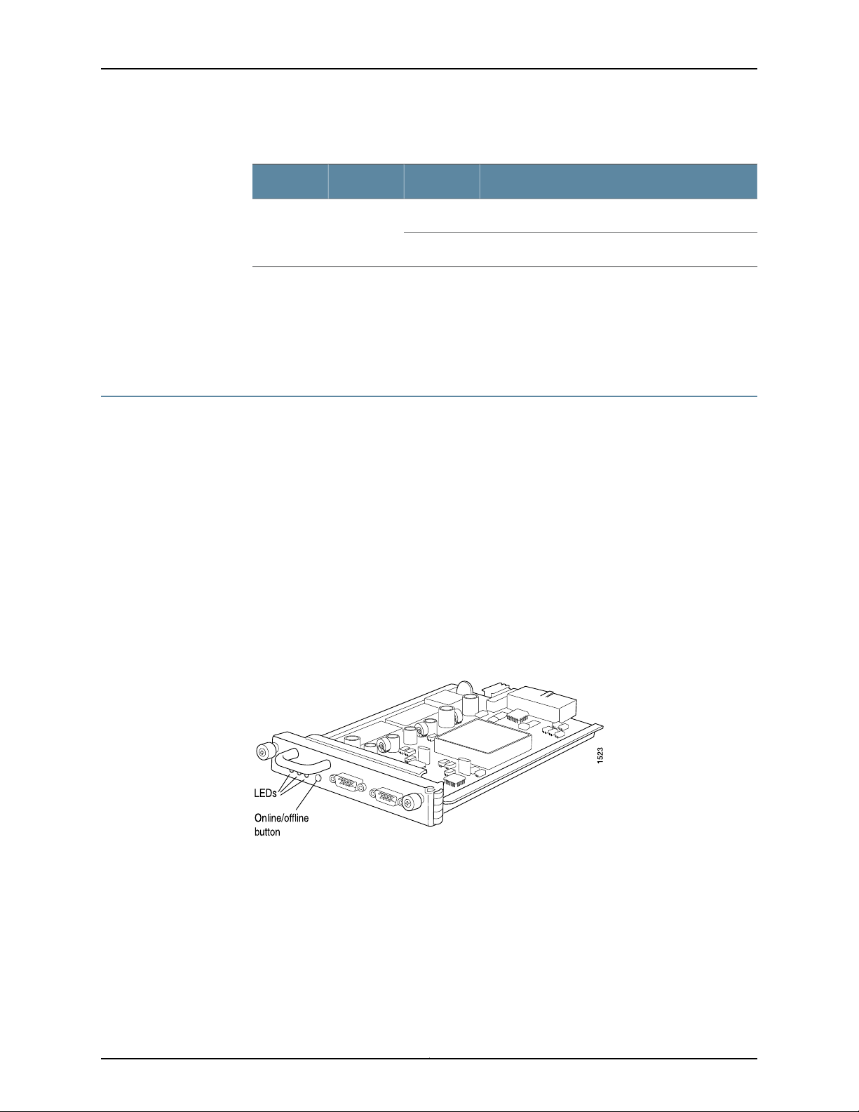
T640 Core Router Hardware Guide
Table 10: T-CB LEDs (continued)
DescriptionStateColorLabel
T-CB is online and is functioning normally.On steadilyGreenOK
T-CB is powering up, but not online.Blinking
Related
Documentation
T640 Chassis Description on page 13•
• Replacing a T640 T-CB on page 201
• Maintaining the T640 T-CBs on page 149
T640 SONET Clock Generators (SCGs) Overview
•
T640 Standard SONET Clock Generators (SCGs) Description on page 40
•
T640 SONET Clock Generators (SCGs) LEDs on page 41
T640 Standard SONET Clock Generators (SCGs) Description
The SONET Clock Generators (SCGs) provide 19.44-MHz Stratum 3 clock signal for the
SONET/SDH interfaces on the router (see Figure 22 on page 40).
One SCG is shipped as part of the standard router configuration, but up to two SCGs can
be installed to provide redundancy. SCGs are installed into the upper rear of the chassis
in the slots labeled SCG0 and SCG1.
Backup SCGs are hot-removable and hot-insertable. Master and nonredundant SCGs
are hot-pluggable.
Figure 22: SCG
Each standard SCG consists of the following components:
•
19.44-MHz Stratum 3 clock.
•
Field-programmable gate array (FPGA) that performs multiplexing of clock sources.
•
Three LEDs, located on the SCG faceplate, that display the status of the SCG.
•
SCG online/offline button, located on the SCG faceplate.
•
Two external clock inputs.
Copyright © 2010, Juniper Networks, Inc.40
Page 71

Chapter 3: T640 Router Hardware Component Overview
NOTE: The external clock inputs are not supported on the standard SONET
Clock Generator (SCG) .
Related
Documentation
Replacing a T640 SCG on page 210•
• Maintaining the T640 SCGs on page 150
• Locating the T640 SCG Serial Number Label on page 375
T640 SONET Clock Generators (SCGs) LEDs
Three LEDs, located on the SCG faceplate, display the status of the SCG. Table 11 on
page 41 describes the functions of the SCG LEDs.
Table 11: SCG LEDs
Related
Documentation
Replacing a T640 SCG on page 210•
• Maintaining the T640 SCGs on page 150
DescriptionStateColorLabel
On steadilyGreenOK
SCG is online and is functioning
normally.
SCG has failed.On steadilyYellowFAIL
SCG is functioning as master.On steadilyBlueMASTER
• Locating the T640 SCG Serial Number Label on page 375
T640 Craft Interface Overview
•
T640 Craft Interface Description on page 41
•
T640 Craft Interface Alarm LEDs and ACO/LT Button on page 42
•
T640 Craft Interface LCD and Navigation Buttons on page 43
•
T640 Craft Interface Host Subsystem LEDs on page 44
•
T640 Craft Interface SIB LEDs on page 45
•
T640 Craft Interface FPC LEDs and Online/Offline Buttons on page 45
T640 Craft Interface Description
The craft interface allows you to view status and troubleshooting information at a glance
and to perform many system control functions. It is hot-insertable and hot-removable.
The craft interface is located on the front of the router above the FPCs and contains the
following:
41Copyright © 2010, Juniper Networks, Inc.
Page 72
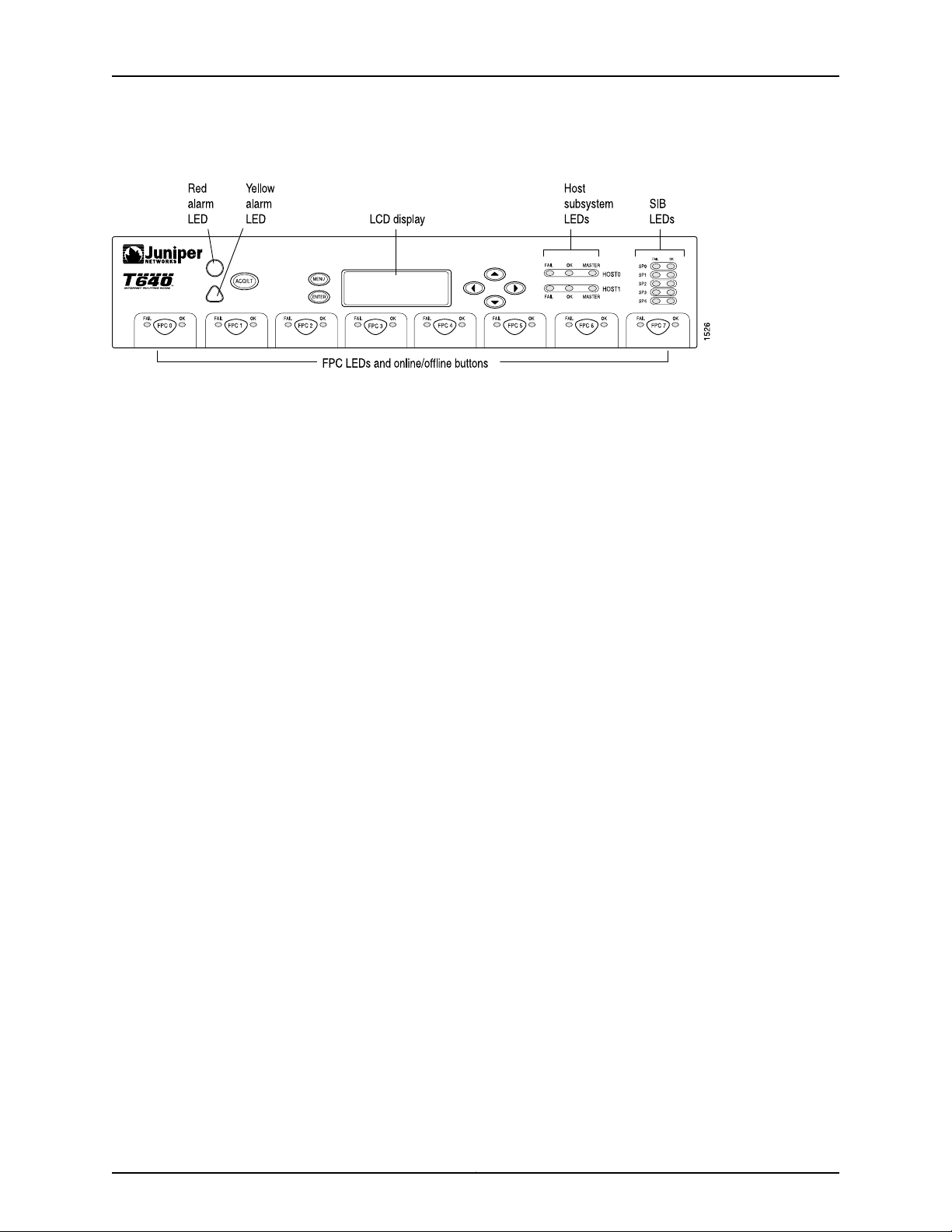
T640 Core Router Hardware Guide
Figure 23: Front Panel of the T640 Craft Interface
Related
Documentation
T640 Chassis Description on page 13•
• Troubleshooting Using the T640 Craft Interface LEDs
• Replacing a T640 Craft Interface on page 196
T640 Craft Interface Alarm LEDs and ACO/LT Button
Two large alarm LEDs are located at the upper left of the craft interface (see Figure 23
on page 42). The circular red LED lights to indicate a critical condition that can result in
a system shutdown. The triangular yellow LED lights to indicate a less severe condition
that requires monitoring or maintenance. Both LEDs can be lit simultaneously.
A condition that causes an LED to light also activates the corresponding alarm relay
contact on the connector interface panel (CIP), as described in “T640 Alarm Relay
Contacts” on page 48. The LCD on the craft interface reports the cause of the alarm, as
described in “T640 Craft Interface LCD and Navigation Buttons” on page 43.
To deactivate red and yellow alarms, press the button labeled ACO/LT (for “alarm
cutoff/lamp test”), which is located to the right of the alarm LEDs. Deactivating analarm
turns off both LEDs and deactivates the device attached to the corresponding alarm
relay contact on the CIP. However, the LCD continues to report the alarm message until
you clear the condition that caused the alarm.
Table 12 on page 43 describes the alarm LEDs and alarm cutoff button in more detail.
Copyright © 2010, Juniper Networks, Inc.42
Page 73
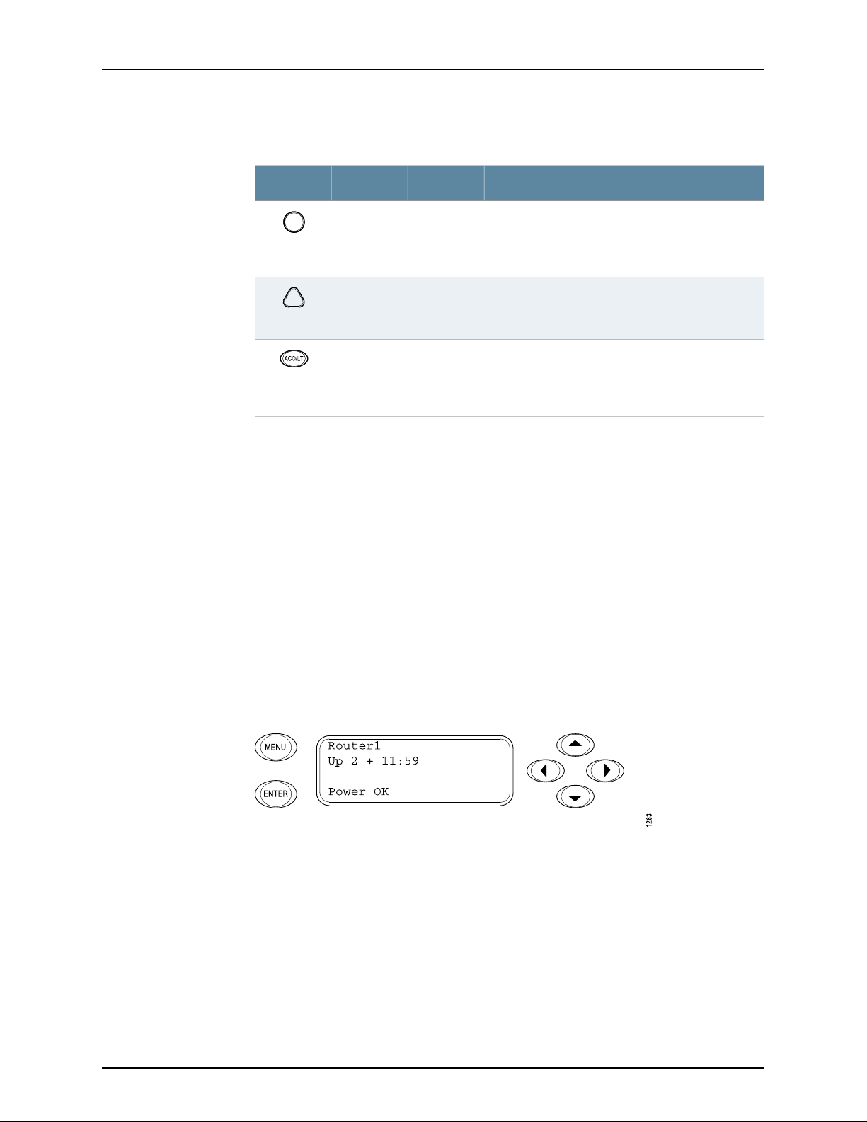
Chapter 3: T640 Router Hardware Component Overview
Table 12: Alarm LEDs and Alarm Cutoff/Lamp Test Button
DescriptionStateColorShape
On steadilyRed
On steadilyYellow
——
Related
Documentation
T640 Chassis Description on page 13•
• Troubleshooting Using the T640 Craft Interface LEDs
• Replacing a T640 Craft Interface on page 196
T640 Craft Interface LCD and Navigation Buttons
A four-line LCD is located in the craft interface, along with six navigation buttons. The
LCD operates in two modes:
•
LED Idle Mode
Critical alarm LED—Indicates a criticalcondition that
can cause the router to stop functioning. Possible
causes include component removal, failure, or
overheating.
Warningalarm LED—Indicatesa seriousbut nonfatal
error condition, such as a maintenance alert or a
significant increase in component temperature.
Alarm cutoff/lamp test button—Deactivates red and
yellowalarms. Causesall LEDs on the craft interface
to light (for testing purposes), when pressed and
held.
•
LED Alarm Mode
During normal operation, the LCD operates in idle mode and reports current status
information, as shown in Figure 24 on page 43.
Figure 24: T640 LCD in Idle Mode
The lines in the display report the following information:
•
First line—Router name.
•
Second line—Length of time the router has been running, reported in the following
form:
Up days + hours:minutes
43Copyright © 2010, Juniper Networks, Inc.
Page 74
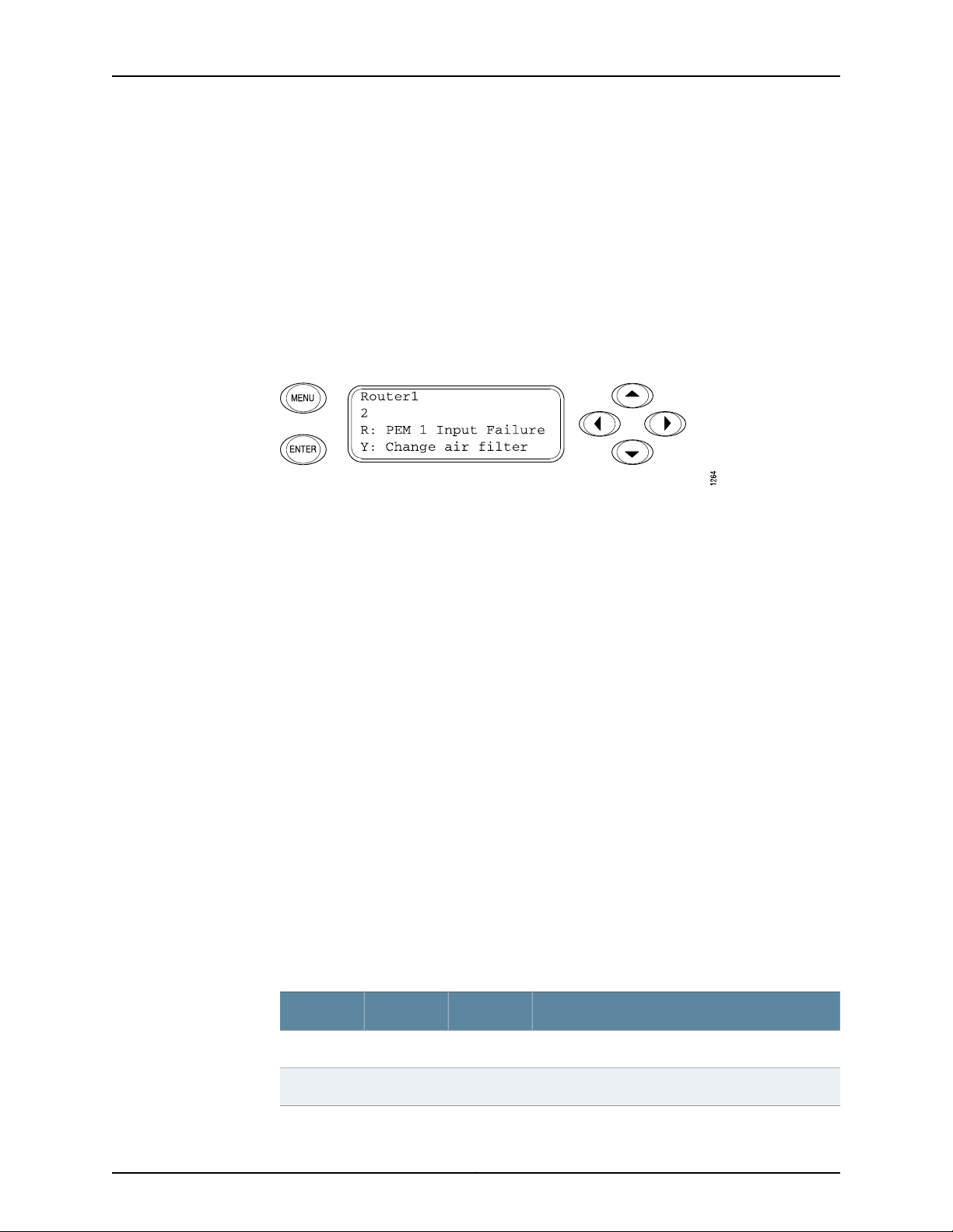
T640 Core Router Hardware Guide
•
To add a message that alternates every 2 seconds with the default status messages,
use the set chassis display message command. For more information, see the Junos OS
System Basics and Services Command Reference.
When a red or yellow alarm occurs, the LCD switches to alarm mode and reports the
alarm condition, as shown in Figure 25 on page 44.
Figure 25: T640 LCD in Alarm Mode
The lines in the display report the following information:
Third and fourth lines—Status messages, which rotate at 2-second intervals. Some
conditions, such as removal or insertion of a system component, can interrupt the
messages.
•
First line—Router name.
•
Second line—Number of active alarms.
•
Third and fourth lines—Individual alarm messages, with the most severe condition
shown first. The prefix oneach line indicates whether the alarm isa red(R) or yellow (Y)
alarm.
For a list of alarm messages that can appear on the LCD, see “Troubleshooting Using the
T640 Chassis and Interface Alarm Messages” on page 165.
Related
Documentation
T640 Chassis Description on page 13•
• Troubleshooting Using the T640 Craft Interface LEDs
• Replacing a T640 Craft Interface on page 196
T640 Craft Interface Host Subsystem LEDs
Each host subsystem has three LEDs, located on the upper right of the craft interface,
that indicate its status. The LEDs labeled HOST0 show the status of the Routing Engine
in slot RE0 and the T-CB in slot CB0. The LEDs labeled HOST1 show the status of the
Routing Engine in slot RE1 and the T-CB in slot CB1. Table 13 on page 44 describes the
functions of the host subsystem LEDs.
Table 13: T640 Host Subsystem LEDs
DescriptionStateColorLabel
Host is offline.On steadilyRedFAIL
Host is online and is functioning normally.On steadilyGreenOK
Copyright © 2010, Juniper Networks, Inc.44
Page 75

Chapter 3: T640 Router Hardware Component Overview
Table 13: T640 Host Subsystem LEDs (continued)
DescriptionStateColorLabel
Host is functioning as the master.On steadilyGreenMASTER
Related
Documentation
T640 Chassis Description on page 13•
• Troubleshooting Using the T640 Craft Interface LEDs
• Replacing a T640 Craft Interface on page 196
T640 Craft Interface SIB LEDs
Each SIBhas two LEDson the craft interfacethat indicate its status. The SIB LEDs, labeled
SIB0 through SIB4, are located on the upper right of the craft interface. The ACTIVE LED
is not replicated on the craft interface. Table 14 on page 45 describes the functions of
the SIB LEDs.
Table 14: SIB LEDs on the Craft Interface
Related
Documentation
T640 Chassis Description on page 13•
• Troubleshooting Using the T640 Craft Interface LEDs
• Replacing a T640 Craft Interface on page 196
DescriptionStateColorLabel
SIB has failed.On steadilyRedFAIL
SIB is functioning normally.On steadilyGreenOK
T640 Craft Interface FPC LEDs and Online/Offline Buttons
Each FPC slot has two LEDs that indicate its status.The FPC LEDs, labeled FPC0 through
FPC7, are located along the bottom of the craft interface. Table 15 on page 45 describes
the functions of the FPC LEDs.
Table 15: FPC LEDs
DescriptionStateColorLabel
FPC has failed.On steadilyRedFAIL
FPC is functioning normally.On steadilyGreenOK
FPC is starting up.Blinking
45Copyright © 2010, Juniper Networks, Inc.
Page 76

T640 Core Router Hardware Guide
Related
Documentation
T640 Chassis Description on page 13•
• Troubleshooting Using the T640 Craft Interface LEDs
• Replacing a T640 Craft Interface on page 196
T640 Connector Interface Panel (CIP) Description
The Connector Interface Panel (CIP) consists of Ethernet, console, and auxiliary
connectors for the Routing Engines and alarm relay contacts (see Figure 26 on page 47).
The front electrostatic discharge point is located near the bottom of the CIP. The CIP is
located at the left side of the FPC card cage.
The CIP is hot-pluggable.
Copyright © 2010, Juniper Networks, Inc.46
Page 77
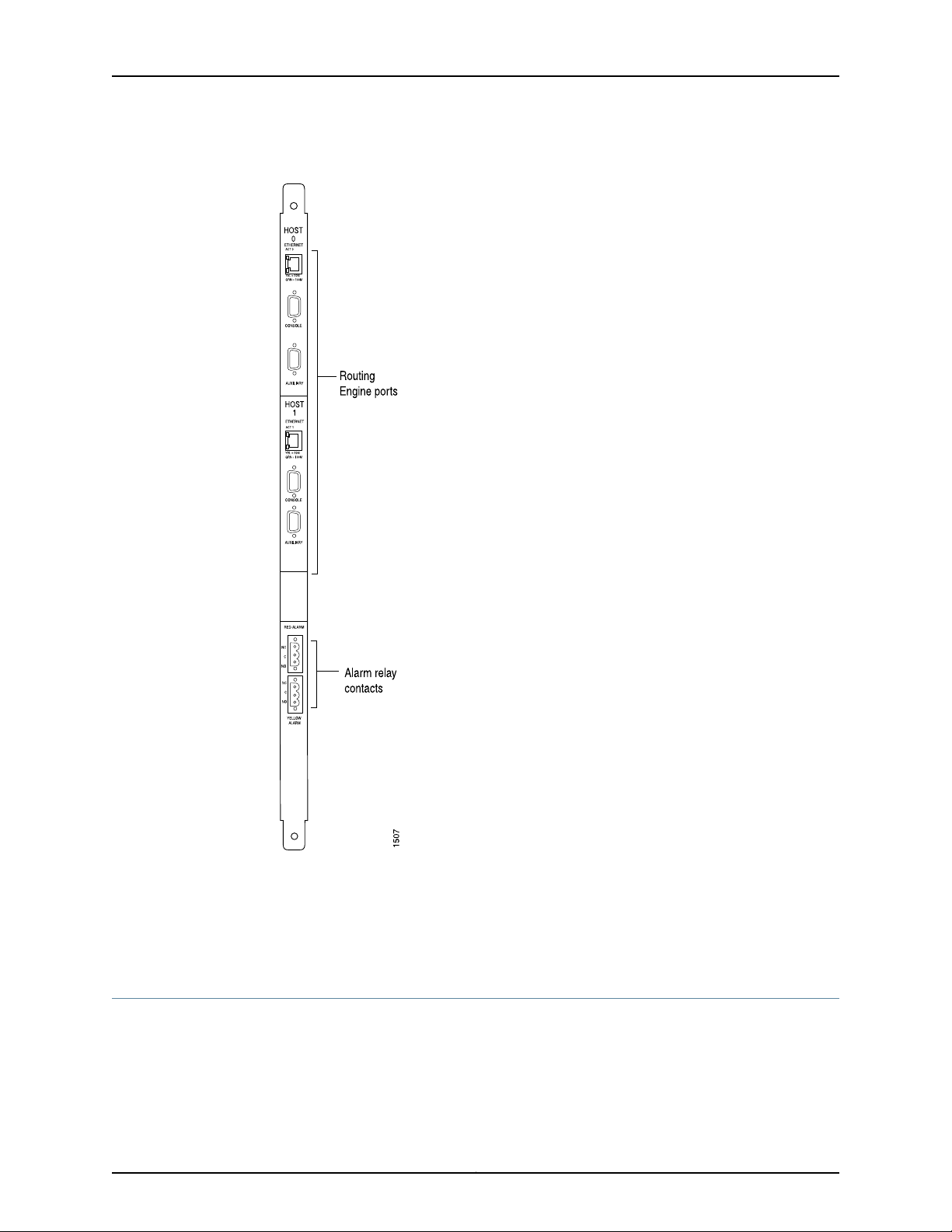
Figure 26: CIP
Chapter 3: T640 Router Hardware Component Overview
Related
Documentation
T640 Chassis Description on page 13•
• Replacing the T640 CIP on page 177
• Locating the T640 CIP Serial Number Label on page 371
T640 Routing Engine Ports
The CIP has two sets of ports that you use to connect the Routing Engines to external
management devices. Fromthese management devices, youcan use theCLI toconfigure
the router.
47Copyright © 2010, Juniper Networks, Inc.
Page 78

T640 Core Router Hardware Guide
The upper set of ports, labeled HOST 0, connects to the Routing Engine in slot RE0; and
the lower set, labeled HOST 1, connectsto theRouting Enginein slotRE1. Eachset includes
the following ports:
•
•
•
ETHERNET—Connects the Routing Engine through an Ethernet connection to a
management LAN (or any other device that plugs into an Ethernet connection) for
out-of-band management. The port uses an autosensing RJ-45 connector to support
both 10- and 100-Mbps connections. Two small LEDs on the left edge of the port
indicate the connection in use: the yellow LED lights for a 10-Mbps connection and the
green LED lights for a 100-Mbps connection.
CONSOLE—Connects the Routing Engine to a system console through an RS-232
(EIA-232) serial cable.
AUXILIARY—Connects theRouting Engine to a laptop,modem, or other auxiliary device
through an RS-232 (EIA-232) serial cable.
Related
Documentation
T640 Connector Interface Panel (CIP) Description on page 46•
• T640 DB-9 Connector Pinouts for the Routing Engine AUXILIARY and CONSOLE Ports
on page 368
• T640 RJ-45 Connector Pinouts for the Routing Engine ETHERNET Port on page 367
• Replacing the T640 Connections to Routing Engine Interface Ports on page 180
T640 Alarm Relay Contacts
The CIPhas two alarm relay contacts for connecting the router to external alarmdevices.
Whenever a system condition triggers eitherthe red oryellowalarm onthe craft interface,
the alarm relay contacts are also activated. The alarm relay contacts are located below
the Routing Engine ports. The terminal blocks that plug into the alarm relay contacts are
supplied with the router. They accept wire of any gauge between 28-AWG and 14-AWG
(0.08 and 2.08 mm2), which is not provided. Use the gauge of wire appropriate for the
external device you are connecting.
Related
Documentation
T640 Connector Interface Panel (CIP) Description on page 46•
• Replacing the T640 Alarm Relay Wires on page 184
• T640 Routing Engine Interface Cable and Wire Specifications on page 365
• T640 Routing Engine Ports on page 47
T640 Power System Overview
•
T640 Power System Description on page 49
•
T640 Two-Input 160-A DC Power Supply Overview on page 49
•
T640 Two-Input 160-A DC Power Supply LEDs on page 51
•
T640 Three-Input 240-A DC Power Supply Overview on page 52
Copyright © 2010, Juniper Networks, Inc.48
Page 79

•
T640 Three-Input 240-A DC Power Supply LEDs on page 53
•
T640 Four-Input 240-A DC Power Supply Overview on page 55
•
T640 Four-Input 240-A DC Power Supply LEDs on page 56
•
T640 Three-Phase Delta and Wye AC Power Supply Overview on page 57
•
T640 Three-Phase Delta and Wye AC Power Supply LEDs on page 60
T640 Power System Description
The T640 Core Router supports these power supplies:
•
Two Two-input 160-A DC power supplies are supported in Junos OS Release 5.3 and
later.
•
Two Three-input 240-A DC power supplies in 2-INPUT mode are supported in Junos
OS Release 8.5 and later.
•
Two Four-input 240-A DC power supplies are supported in Junos OS Release 10.0 and
later.
Chapter 3: T640 Router Hardware Component Overview
NOTE: Mixing power supplies with a different number of inputs in the same
router is supported only during upgrade. Mixing different types of power
supplies is not supported during normal operations.
Related
Documentation
Powering On a DC-Powered T640 Router on page 130•
• Maintaining the T640 Power Supplies on page 159
• T640 DC Power System Electrical Specifications on page 347
T640 Two-Input 160-A DC Power Supply Overview
•
Two-Input 160-A DC Power Supply Description on page 49
•
Two-Input 160-A DC Power Supply Inputs on page 50
•
Two-Input 160-A DC Power Supply Load Sharing and Fault Tolerance on page 50
Two-Input 160-A DC Power Supply Description
Each two-input 160-A DC power supply weighsapproximately 23lb (10.5kg) andconsists
of two inputs, two 80-A (@ –48 VDC) circuit breakers, a fan, and LEDs to monitor the
status of the power supply. Figure 27 on page 50 shows the two-input 160-A DC power
supply.
49Copyright © 2010, Juniper Networks, Inc.
Page 80
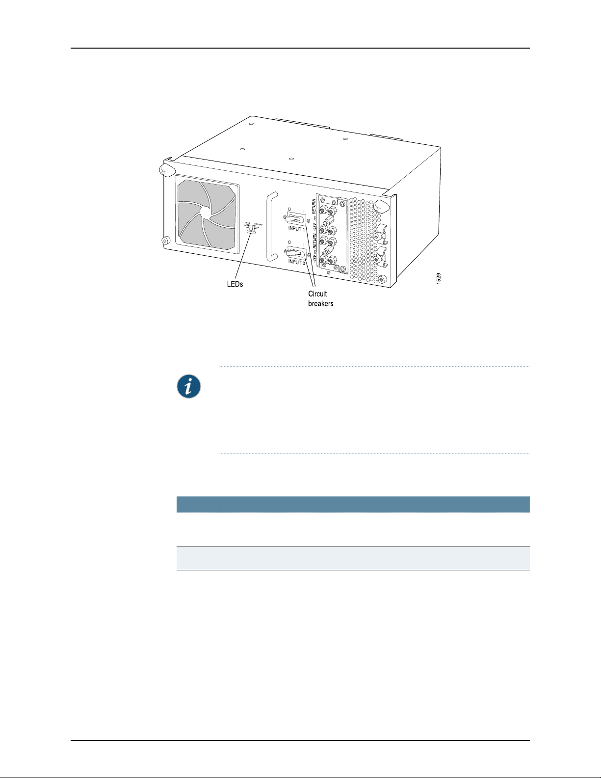
T640 Core Router Hardware Guide
Figure 27: Two-Input 160-A DC Power Supply
Two-Input 160-A DC Power Supply Inputs
Each two-input 160-A DC power supply has two inputs—INPUT 1 and INPUT 0, from top
to bottom—each with its own 80-A (@ –48 VDC) circuit breaker.
NOTE: All inputs on the two-input 160-A DC powersupply in slotPEM0 must
be powered by dedicatedpower feeds derived from feed A, and all inputs on
the two-input 160-A DC power supply in slot PEM1 must be powered by
dedicated power feeds derived from feed B. This configuration provides the
commonly deployed A/B feed redundancy for the system.
Table 16 on page 50 describes which components are powered by each input.
Table 16: Components Powered by Each Input
Provides Power to These ComponentsInput
INPUT 0
Two-Input 160-A DC Power Supply Load Sharing and Fault Tolerance
When the router is operating normally and both power supplies in a redundant power
system are switched on, load sharing between them occurs automatically. When one
power supply fails or is turned off, the other power supply immediately assumes the
entire electrical load for the system. A single power supply with both inputs active can
provide full power for as long as the router is operational. Table 17 on page 51 describes
the behavior of the two-input160-A DC power supply and router if one of the inputs fails.
FPCs in slots FPC0 and FPC1, SIBs, T-CBs, Routing Engines, CIP, craft interface, and
fan trays
FPCs in slots FPC2 through FPC7INPUT 1
Copyright © 2010, Juniper Networks, Inc.50
Page 81

Table 17: Fault Tolerance
Fault Tolerance When One Input Fails or Is DisconnectedRedundancy
Nonredundant power
supplies
If either input fails, the router shuts down.
NOTE: We recommend that you install redundant power supplies.
Chapter 3: T640 Router Hardware Component Overview
If either input on one power supply fails, the other power supply
assumes the electrical load for both inputs. If one of the inputs on
the other power supply is not functional, the router shuts down.
Related
Documentation
Redundantpowersupplies
T640 Power System Description on page 49•
• Powering On a DC-Powered T640 Router on page 130
• Maintaining the T640 Power Supplies on page 159
T640 Two-Input 160-A DC Power Supply LEDs
Four LEDs on each two-input 160-A DC power supply faceplate indicate the status of
the power supply. In addition, a power supply failure triggers the red alarm LED on the
craft interface. Table 18 on page 51 describes the functions of the power supply LEDs.
Table 18: Two-Input 160-A DC Power Supply LEDs
On steadilyYellowCB TRIP
DescriptionStateColorLED
Circuit breaker is on.On steadilyGreenCB OK
Circuit breaker is off.Off
Circuit breaker is not turned on, or host subsystem
has detected a failure and has turned the circuit
breaker off.
Off
On steadilyYellowOVER TEMP
Off
On steadilyBlueDC OK
Blinking
No problems have occured with circuit breaker, or
the power supply is off.
Power supply has exceeded recommended
temperature.
Power supply is within the recommended
temperature or is not turned on.
Power supply is installed correctly and is
functioning normally.
Power supply is starting up, is not properly
installed, or is not functioning correctly. One of the
inputs mighthave failed, or the power supplymight
not be receiving sufficient power.
Power supply is not powered on.Off
51Copyright © 2010, Juniper Networks, Inc.
Page 82

T640 Core Router Hardware Guide
Related
Documentation
T640 Power System Description on page 49•
• Powering On a DC-Powered T640 Router on page 130
• Maintaining the T640 Power Supplies on page 159
T640 Three-Input 240-A DC Power Supply Overview
•
Three-Input 240-A DC Power Supply Description on page 52
•
Three-Input 240-A DC Power Supply Inputs on page 52
•
Three-Input 240-A DC Power Supply Load Sharing and Fault Tolerance on page 53
Three-Input 240-A DC Power Supply Description
Each three-input 240-A DCpower supply weighsapproximately 25 lb(11.3 kg)and consists
of three inputs, three 80-A circuit breakers, a fan, and LEDs to monitor the status of the
power supply. Figure 28 on page 52 shows the three-input 240-A DC power supply in
2-INPUT mode.
Figure 28: Three-Input 240-A DC Power Supply
Three-Input 240-A DC Power Supply Inputs
The three-input 240-A DC powersupply inputsare labeled INPUT 0, INPUT 1, and INPUT2,
from top to bottom. Each input consists of –48 VDC and return, each with its own 80-A
circuit breaker. The input mode switch on the faceplate allows you to set the DC power
supply to either 2–INPUT or 3–INPUTmode. 2-INPUTmode isrequired for the T640router
and TX Matrix router.
Table 19 on page 53 describes which components are powered by each input.
Copyright © 2010, Juniper Networks, Inc.52
Page 83

Chapter 3: T640 Router Hardware Component Overview
Table 19: Components Powered by Each Three-Input 240-A DC Power
Supply Input
Three-Input ModeInput
INPUT 0
T640-SIBs, T-CBs, fan trays, Routing
Engines, and FPCs in slots FPC0 and
FPC1
FPCs in slots FPC2 through FPC7INPUT 1
Related
Documentation
INPUT 2
This input is not supported in 2–INPUT
mode.
Three-Input 240-A DC Power Supply Load Sharing and Fault Tolerance
When the router is operating normally and both power supplies are switched on, load
sharing between them occurs automatically. When one power supply fails or is turned
off, the other power supply immediately assumes theentire electrical loadfor the system.
A single power supply canprovide fullpower for aslong as the router is operational. Table
20 on page 53 describes the behavior of the power supply if one of the inputs fails.
Table 20: Fault Tolerance
Fault Tolerance When One Input Fails or is DisconnectedRedundancy
Nonredundant power supply
Redundant power supplies
T640 Power System Description on page 49•
• Powering On a DC-Powered T640 Router on page 130
If this input fails, the router shuts down.
NOTE: We recommend that you install redundant power
supplies.
If an input on one power supply fails, the other power supply
assumes theelectrical loadfor allinputs. Ifone input on the other
power supply is not functional, the router shuts down.
• Maintaining the T640 Power Supplies on page 159
T640 Three-Input 240-A DC Power Supply LEDs
LEDs on each power supply faceplate (see Figure 29 on page 54) indicate the status of
the power supply. In addition, a power supply failure triggers the red alarm LED on the
craft interface. Table 21 on page 54 describes the functions of the power supply LEDs.
53Copyright © 2010, Juniper Networks, Inc.
Page 84
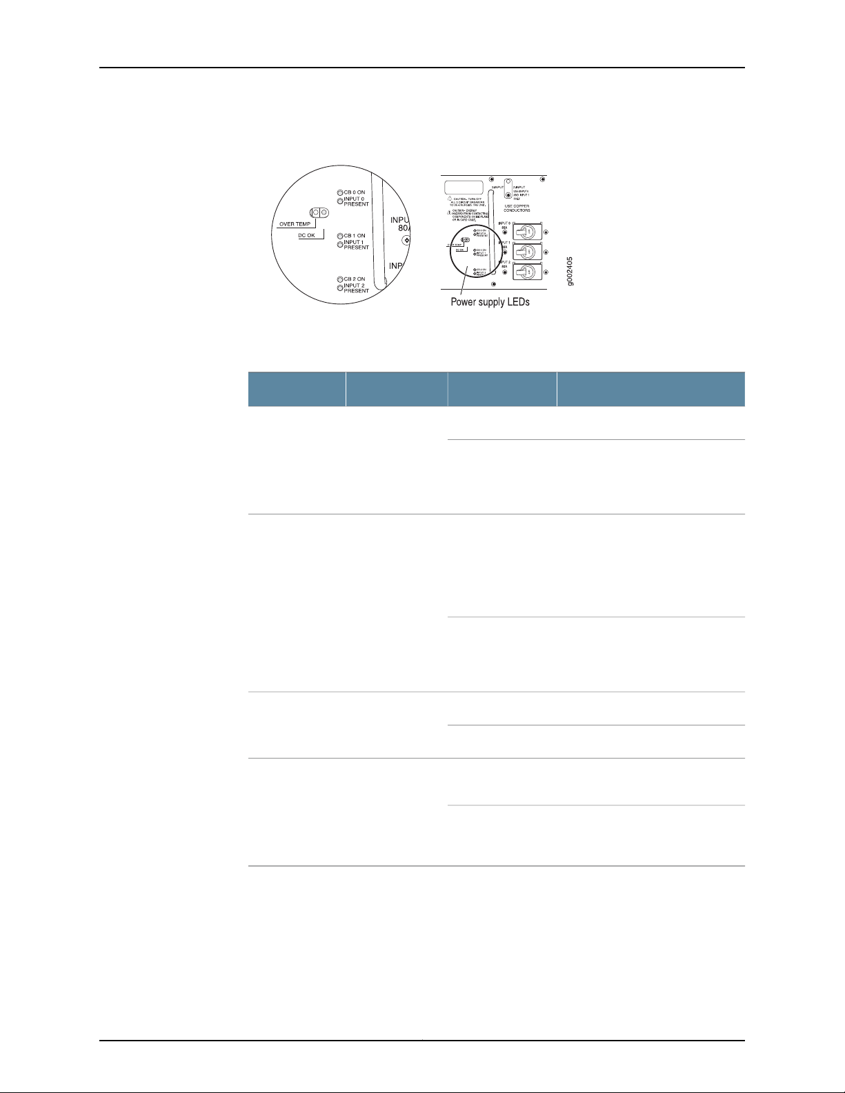
T640 Core Router Hardware Guide
Figure 29: Three-Input 240-A DC Power Supply LEDs
Table 21 on page 54 describes the three-input 240-A DC power supply LEDs.
Table 21: Three-Input 240-A DC Power Supply LEDs
input
Off
DescriptionStateColorLED
Circuit breaker is on.On steadilyGreenCB ON—One per
Circuit breaker is not turned on, or
host subsystem has detected a
failure and has turned the circuit
breaker off.
Related
Documentation
On steadilyBlueDC OK—One per
power supply
Blinking
PRESENT—One
per input
On steadilyYellowOVER
TEMP—One per
power supply
Off
T640 Power System Description on page 49•
• Powering On a DC-Powered T640 Router on page 130
When the power supply is correctly
set to 2-INPUT mode and INPUT 0
and INPUT1 are properlyenergized,
the DC OK LED indicates that the
power supply is functioning
normally.
Power supply is starting up, is not
functioning, is not properly
installed, or is not operating
properly.
Input is receiving voltage.On steadilyGreenINPUT
Input voltage is not present.Off
Power supply has exceeded
recommended temperature.
Power supply is within the
recommended temperature or the
power supply is not on.
• Maintaining the T640 Power Supplies on page 159
Copyright © 2010, Juniper Networks, Inc.54
Page 85
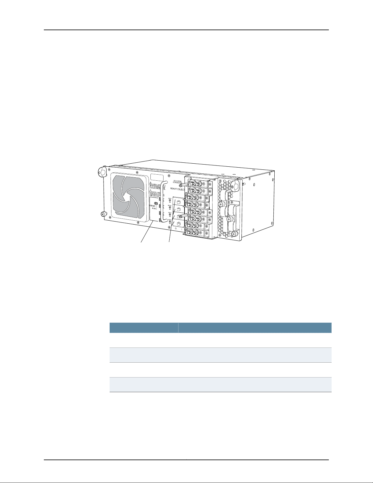
T640 Four-Input 240-A DC Power Supply Overview
g004659
LEDs
Circuit breakers
•
Four-Input 240-A DC Power Supply Description on page 55
•
Four-Input 240-A DC Power Supply Inputs on page 55
•
Four-Input 240-A DC Power Supply Load Sharing and Fault Tolerance on page 55
Four-Input 240-A DC Power Supply Description
Each four-input 240-A DC power supply weighs approximately 26.6 lb (12.0 kg) and
consists of four inputs, four 60-A circuit breakers, a fan, and LEDs to monitor the status
of the power supply. Figure 30 on page 55 shows the four-input 240-A DC power supply.
Figure 30: Four-Input 240-A DC Power Supply
Chapter 3: T640 Router Hardware Component Overview
Four-Input 240-A DC Power Supply Inputs
The four-input 240-ADC power supply inputs are labeled INPUT 0, INPUT1, and INPUT 2,
and INPUT 3 from top to bottom. Each input consists of –48 VDC and return, each with
its own 60-A circuit breaker.
Table 22 on page 55 describes which components are powered by each input.
Table 22: Components Powered by Each Four-Input 240-A DC Power
Supply Input
ComponentsInput
SIBs, control boards,Routing Engines, andhalf thesystem fanpowerINPUT 0
FPCs in slots FPC0 and FPC1 and half the system fan powerINPUT 1
FPCs in slots FPC2 through FPC4INPUT 2
FPCs in slots FPC5 through FPC7INPUT 3
Four-Input 240-A DC Power Supply Load Sharing and Fault Tolerance
When the router is operating normally and both power supplies are switched on, load
sharing between them occurs automatically. When one power supply fails or is turned
off, the other power supply immediately assumes theentire electrical loadfor the system.
55Copyright © 2010, Juniper Networks, Inc.
Page 86

CIRCUITBREAKERS FOR MIN. 60
SEC.TO DE-ENERGIZE THE UNIT
COMPLETELYBEFORE TURN ON.
g004660
Power supply LEDs
60A
60A
60A
60A
INPUT 3
T640 Core Router Hardware Guide
A single power supply can provide full power for as long as the router is operational. If
any of the four inputs fails, the router shuts down, and the other power supply assumes
the electrical load for all four inputs.
Related
Documentation
T640 Four-Input 240-A DC Power Supply LEDs on page 56•
• Troubleshooting the T640 Power System on page 171
• Replacing a T640 Four-Input 240-A DC Power Supply on page 254
• T640 DC Power Supply Electrical Specifications on page 348
T640 Four-Input 240-A DC Power Supply LEDs
LEDs on each four-input 240-A DC power supply faceplate (see Table 23 on page 56)
indicate the status of the power supply. In addition, a power supply failure triggers the
red alarm LED on the craft interface. Figure 31on page56 displays the powersupply LEDs.
Figure 31: Four-Input 240-A DC Power Supply LEDs
Table 23: Four-Input 240-A DC Power Supply LEDs
PRESENT—One
per input
input
power supply
Off
On steadilyBlueDC OK—One per
Blinking
DescriptionStateColorLED
Input is receiving voltage.On steadilyGreenINPUT
Input voltage is not present.Off
Circuit breaker is on.On steadilyGreenCB ON—One per
Circuit breaker is not turned on, or
host subsystem has detected a
failure and has turned the circuit
breaker off.
When all four inputs are properly
energized, the DC OK LED indicates
that thepower supplyis functioning
normally.
Either the power supply is starting
up, or it is not functioning, not
properly installed, or not operating
properly.
Copyright © 2010, Juniper Networks, Inc.56
Page 87
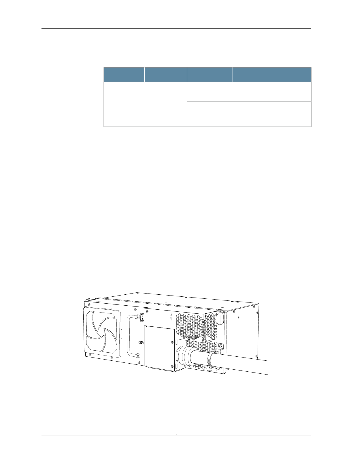
g004953
Chapter 3: T640 Router Hardware Component Overview
Table 23: Four-Input 240-A DC Power Supply LEDs (continued)
DescriptionStateColorLED
On steadilyYellowOVER
TEMP—One per
power supply
Off
Related
Documentation
T640 Four-Input 240-A DC Power Supply Overview on page 55•
• Maintaining the T640 Power Supplies on page 159
• Troubleshooting the T640 Power System on page 171
• Replacing a T640 Four-Input 240-A DC Power Supply on page 254
T640 Three-Phase Delta and Wye AC Power Supply Overview
•
Three-Phase Delta AC Power Supply Description on page 57
•
Three-Phase Wye AC Power Supply Description on page 58
•
AC Power Supply Load Sharing and Fault Tolerance on page 59
Three-Phase Delta AC Power Supply Description
Each three-phase delta AC power supply weighs approximately 31.0 lb (14.06 kg). A
metal wiring compartment contains the AC terminal block and ground labeled GND. The
AC terminal block consists of three input terminals labeled L1, L2, and L3, from left to
right. Thepower switch providespower to the router. Each power supply’s cooling system
consists of two fans, a front air filter, and a side air filter. LEDs provide the status of the
power supply. Figure 32 on page 57 shows the three-phase delta AC power supply.
Power supply has exceeded
recommended temperature.
Power supply is within the
recommended temperature or the
power supply is not on.
Figure 32: Three-Phase Delta AC Power Supply
Figure 33 on page 58 shows the three-phase delta AC power supply connections.
57Copyright © 2010, Juniper Networks, Inc.
Page 88
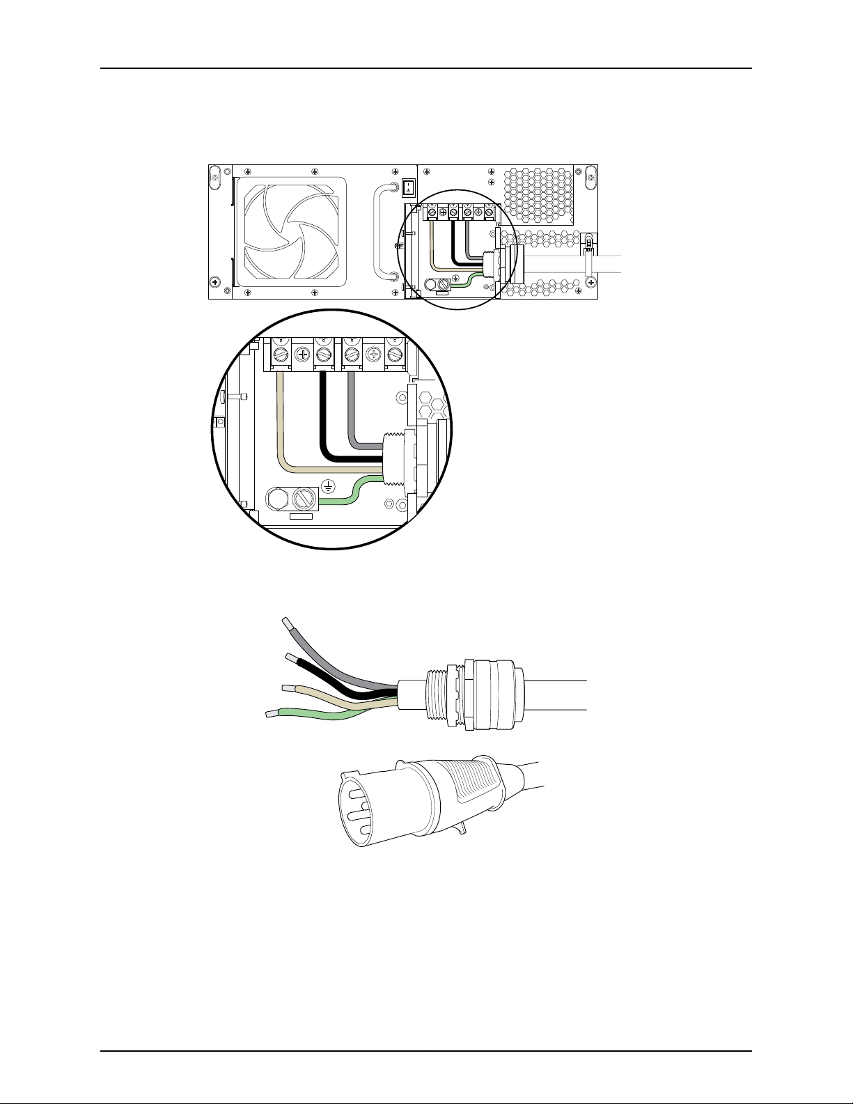
L1 L2 L3
g004951
L1 L2 L3
g004959
T640 Core Router Hardware Guide
Figure 33: Three-Phase Delta AC Power Supply Connections
Figure 34 on page 58 shows the three-phase delta AC power cord.
Figure 34: Three-Phase Delta AC Power Cord
Three-Phase Wye AC Power Supply Description
Each three-phase wye AC power supply weighs approximately 31.0 lb (14.06 kg). A metal
wiring compartment contains the AC terminal block and ground labeled GND. The AC
terminal block consists of four input terminals labeled L1, L2, L3, and N, from left to right.
The power switch provides power to the router. Each power supply’s cooling system
consists of two fans, a front air filter, and a side air filter. LEDs provide the status of the
power supply. Figure 35 on page 59 shows the three-phase wye AC power supply.
Copyright © 2010, Juniper Networks, Inc.58
Page 89
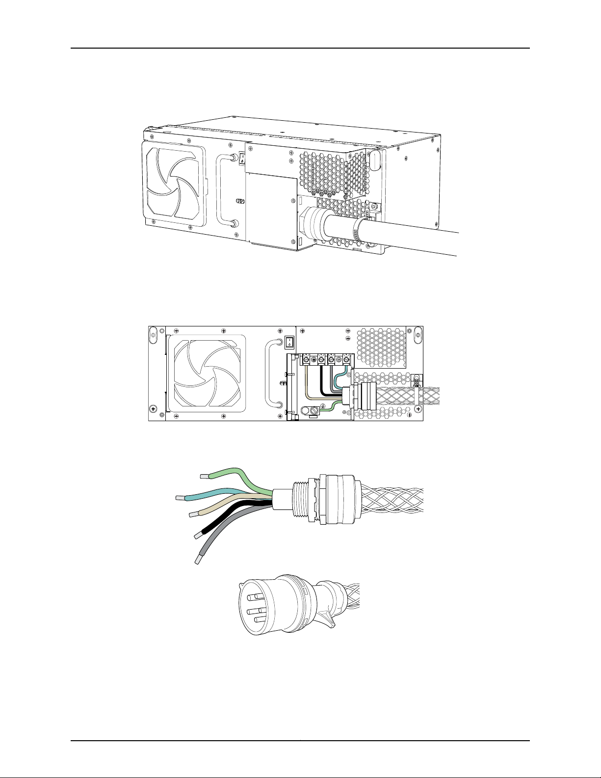
g004953
L1 L2 L3 N
g004950
g004960
Chapter 3: T640 Router Hardware Component Overview
Figure 35: Three-Phase Wye AC Power Supply
Figure 36 on page 59 shows the three-phase wye AC power supply connections.
Figure 36: Three-Phase Wye AC Power Supply Connections
Figure 37 on page 59 shows the three-phase wye AC power cord.
Figure 37: Wye Three-Phase AC Power Cord
AC Power Supply Load Sharing and Fault Tolerance
When the router is operating normally and both power supplies are switched on, load
sharing between them occurs automatically. When one power supply fails or is turned
59Copyright © 2010, Juniper Networks, Inc.
Page 90
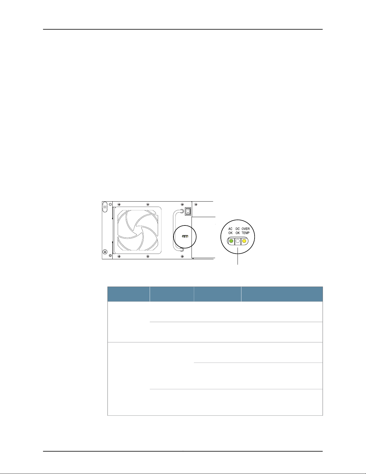
L1 L2 L3
g004952
Power supply LEDs
ACOKDCOKOVER
TEMP
T640 Core Router Hardware Guide
off, the other power supply immediately assumes theentire electrical loadfor the system.
A single power supply can provide full power for as long as the router is operational.
Related
Documentation
T640 Power System Description on page 49•
• T640 Three-Phase Delta and Wye AC Power Supply LEDs on page 60
• Troubleshooting the T640 Power System on page 171
• T640 AC Power Requirements on page 356
• T640 AC Power Cord Specifications on page 358
T640 Three-Phase Delta and Wye AC Power Supply LEDs
Figure 38 on page 60 shows the LEDs on each three-phase delta AC power supply
faceplate. The three-phase wye AC power supply has the same LEDs. The LEDs in Table
24 on page 60 indicate the status of the power supply. In addition, a power supply failure
triggers the red alarm LED on the craft interface.
Figure 38: Delta AC Power Supply LEDs
Table 24: Delta AC Power Supply LEDs
power supply
power supply
On steadilyGreenAC OK—One per
Off–
On steadilyBlueDC OK—One per
Blinking
Off–
DescriptionStateColorLED
The AC terminal block is receiving
voltage.
The AC terminal block is not
receiving voltage.
Power supply is functioning
normally.
Powersupply isstarting up, oris not
functioning or operating properly,
or is not properly installed.
The power supply fails or the AC
terminal block is not receiving
voltage.
Copyright © 2010, Juniper Networks, Inc.60
Page 91
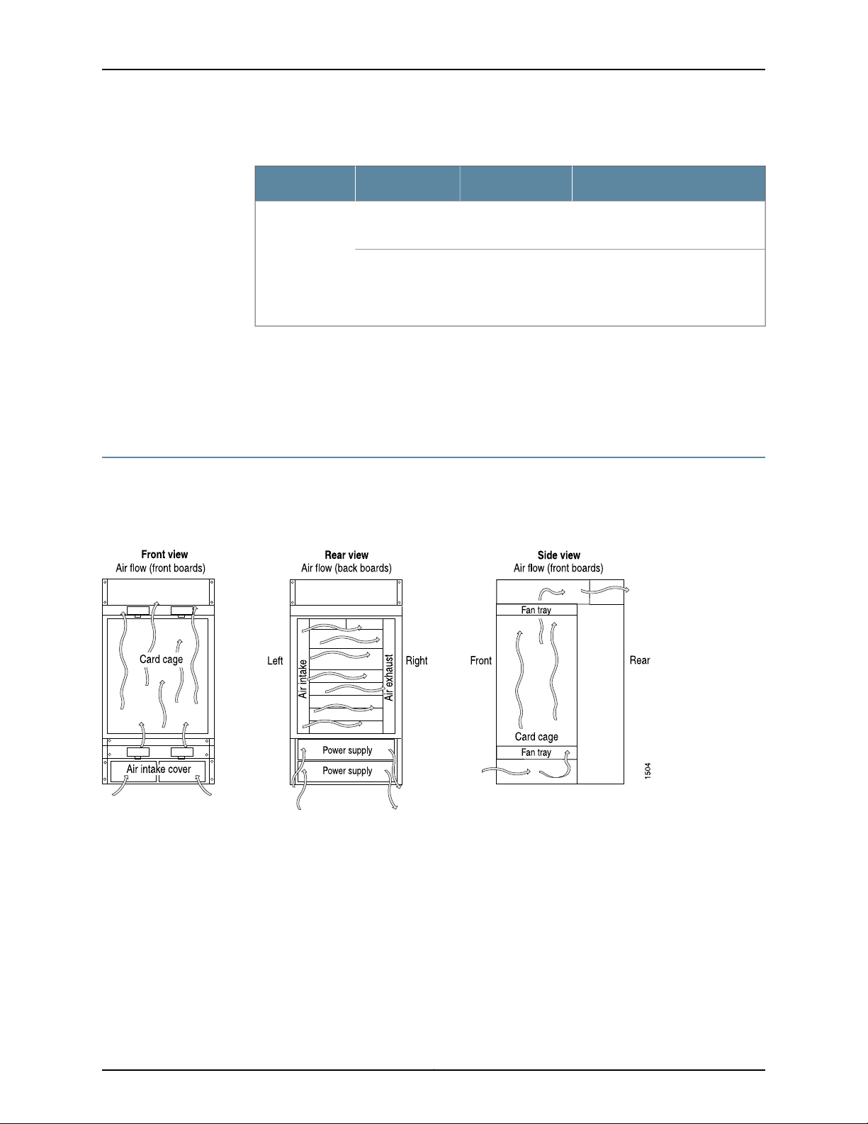
Chapter 3: T640 Router Hardware Component Overview
Table 24: Delta AC Power Supply LEDs (continued)
DescriptionStateColorLED
TEMP—One per
power supply
Related
Documentation
T640 Three-Phase Delta and Wye AC Power Supply Overview on page 57•
• Troubleshooting the T640 Power System on page 171
• T640 AC Power Requirements on page 356
T640 Cooling System Description
The cooling system components work together to keep all router components within the
acceptable temperaturerange. Figure 39on page 61shows the airflowthrough therouter.
Figure 39: Airflow Through the Chassis
On steadilyYellowOVER
Off–
Power supply has exceeded
recommended temperature.
If the DC OK and AC OK are on
steadily, this LED indicates that
power supply is within the
recommended temperature.
The host subsystem monitors the temperature of the router components. When the
router is operating normally, the fans function at lower than full speed. If a fan fails or
the ambient temperature rises above a threshold, the speed of the remaining fans is
automatically adjusted to keep the temperature within the acceptable range. If the
ambient maximum temperature specification is exceeded and the system cannot be
adequately cooled, the Routing Engine shuts down some or all of the hardware
components.
61Copyright © 2010, Juniper Networks, Inc.
Page 92
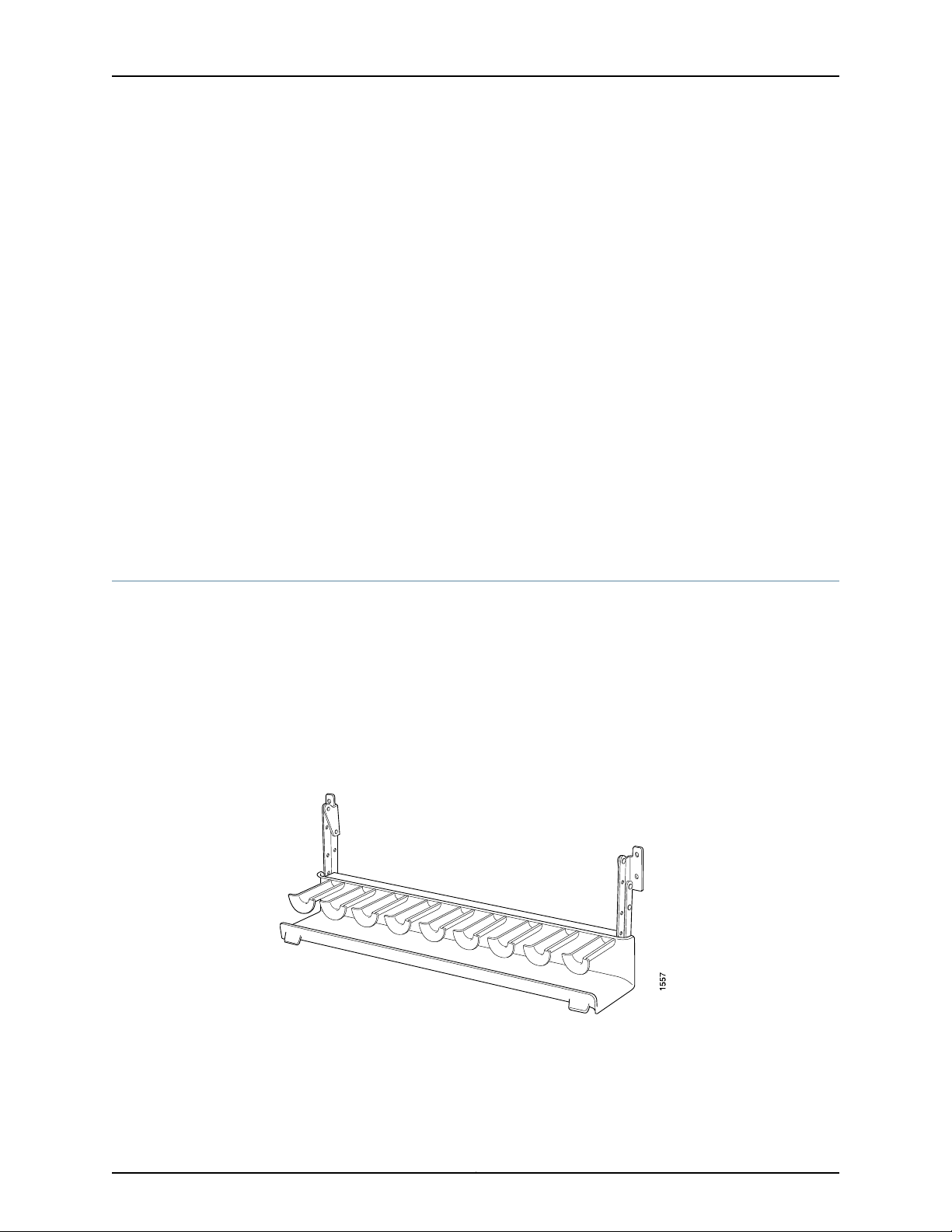
T640 Core Router Hardware Guide
The cooling system consists of the following components:
•
•
•
•
•
All fan trays and filters are hot-insertable and hot-removable.
Two front fan trays—The front fan trays each contain six fans and are interchangeable.
The front fan trays cool the components installed in the front card cage (the FPCs,
PICs, CIP, and midplane).
Front air filter.
Rear fan tray—The rear fan tray contains eight fans or five blowers, and cools the
components installed in the rear card cage (theRouting Engines, Control Boards, SCGs,
and the SIBs). The rear fan tray is not interchangeable with the front trays.
Rear air filter.
Each power supply contains one fan that cools that power supply.
Related
Documentation
Maintaining the T640 Air Filters on page 146•
• Maintaining the T640 Fan Trays on page 147
• Troubleshooting the T640 Cooling System on page 168
T640 Cable Management System Description
The cable management system (see Figure 40 on page 62) consists of a row of nine
semicircular plastic bobbins mounted on the front of therouter below the FPC card cage.
The PIC cables pass between the bobbins and into the tray, keeping the cables organized
and securely in place. The curvature of the bobbins also helps maintain the proper bend
radius for optical PIC cables.
You can pull the cable management system up and outward to lock it into the
maintenance position. This allows you to access the lower fan tray and the front air filter.
Figure 40: Cable Management System
Related
Documentation
• T640 Router Description on page 3
• T640 Chassis Description on page 13
• Removing the T640 Cable Management System on page 102
Copyright © 2010, Juniper Networks, Inc.62
Page 93

PART 2
T640 Router Initial Installation
•
Preparing for T640 Router Installation on page 65
•
T640 Router Installation Overview on page 69
•
Unpacking the T640 Router on page 71
•
Installing the T640 Router Mounting Hardware on page 77
•
Installing the T640 Router in to a Rack on page 85
•
Installing the T640 Router Using a Mechanical Lift on page 87
•
Installing the T640 Router Without a Mechanical Lift on page 95
•
Grounding the T640 Router on page 115
•
Connecting the T640 Router to External Devices on page 117
•
Providing Power to the T640 Router on page 123
•
Performing the Initial T640 Junos OS Configuration on page 139
63Copyright © 2010, Juniper Networks, Inc.
Page 94

T640 Core Router Hardware Guide
Copyright © 2010, Juniper Networks, Inc.64
Page 95

CHAPTER 4
Preparing for T640 Router Installation
•
T640 Site Preparation Checklist on page 65
•
T640 Rack Requirements on page 66
•
T640 Clearance Requirements for Airflow and Hardware Maintenance on page 68
T640 Site Preparation Checklist
The checklist in Table 25 on page 65 summarizes the tasks you need to perform when
preparing a site for router installation.
Table 25: Site Preparation Checklist
DatePerformed ByFor More InformationItem or Task
Environment
Verify that environmental factors such as
temperatureand humidity donot exceedrouter
tolerances.
“T640 Environmental Specifications”
on page 343
Power
Measure distance between external power
sources and router installation site.
Locate sites for connection of system
grounding.
Calculate the power consumption and
requirements.
Rack
Verify that your rack meets the minimum
requirements for the installation of the router.
Plan rack location, including required space
clearances.
“T640 DC Power Distribution” on
page 353
“T640 DC Power Cable
Specifications” on page 352
“T640 Chassis Grounding Cable and
Lug Specifications” on page 345
“T640 DC Power System
Requirements” on page 350
“T640 Rack Requirements” on
page 66
“T640 Clearance Requirements for
Airflow and Hardware Maintenance”
on page 68
65Copyright © 2010, Juniper Networks, Inc.
Page 96

T640 Core Router Hardware Guide
Table 25: Site Preparation Checklist (continued)
DatePerformed ByFor More InformationItem or Task
If arack isused, secure rack tofloor andbuilding
structure.
Cables
Acquire cables and connectors:
•
Determine the number of cables needed
based on your planned configuration.
•
Review the maximum distance allowed for
each cable. Choose the length ofcable based
on the distance between the hardware
components being connected.
Plan the cable routing and management.
Related
Documentation
T640 Router Installation Summary on page 69•
• Safety Requirements, Warnings, and Guidelines for Installing the T640 Router on
page 85
• T640 Chassis Lifting Guidelines on page 310
T640 Rack Requirements
“T640 Rack Requirements” on
page 66
“Calculating Power Budget for
Fiber-Optic Cable for M Series, MX
Series, and T Series Routers” on
page 363
“Calculating Power Margin for
Fiber-Optic Cable for M Series, MX
Series, and T Series Routers” on
page 363
“Maintaining T640 PICs and PIC
Cables” on page 156
The T640 Core Router can be installed in a rack or cabinet. Many types of racks are
acceptable, including four-post (telco) racks and open-frame racks. An example of an
open-frame rack is shown in Figure 41 on page 67.
The router isdesigned forinstallation in a 19-in. rack as defined in Cabinets, Racks, Panels,
and Associated Equipment (document number EIA-310-D) published by the Electronics
Industry Association (http://www.eia.org).
With the use ofadapters, therouter is designed to fit intoa 600-mm-wide rack, asdefined
in the four-part Equipment Engineering (EE); European telecommunications standard for
equipment practice (document numbers ETS 300 119-1 through 119-4) published by the
European Telecommunications Standards Institute (http://www.etsi.org). Use approved
wing devices to narrow the opening between the rails.
The rack rails must be spaced widely enough to accommodate the router chassis's
external dimensions: 37.45 in. (95.1 cm) high, 31 in.(78.7 cm)deep, and 17.43 in. (44.3 cm)
wide. The outer edges of the mounting brackets extend the width to 19 in. (48.3 cm). The
spacing of rails and adjacent racks must also allow for the clearances around the router
and rack that are specified in “T640 Clearance Requirements for Airflow and Hardware
Maintenance” on page 68.
Copyright © 2010, Juniper Networks, Inc.66
Page 97
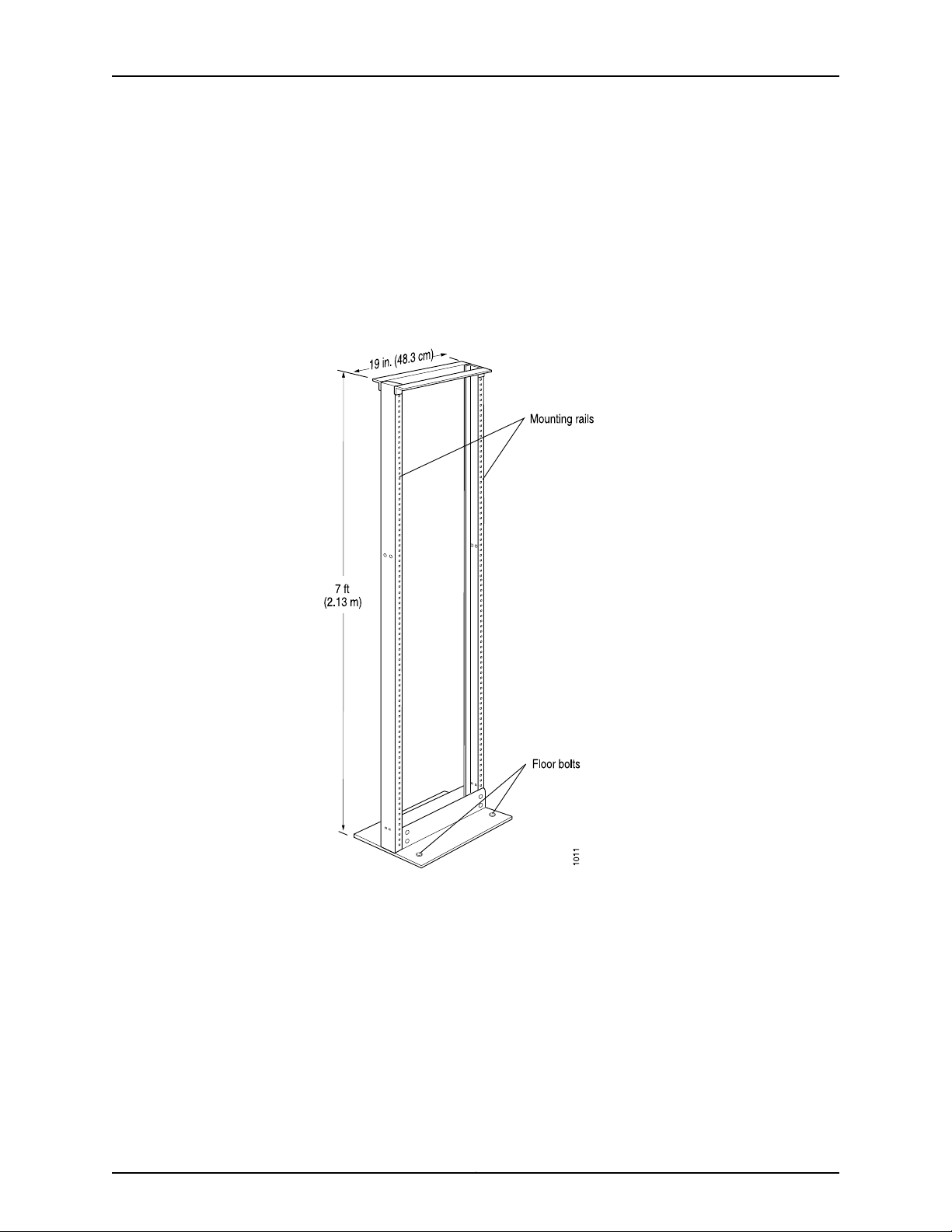
Chapter 4: Preparing for T640 Router Installation
The chassis height of 37.45 in. (95.1 cm) is approximately 21.4 U. A U is the standard rack
unit defined in Cabinets, Racks, Panels, and Associated Equipment (document number
EIA-310-D) published by the Electronics Industry Association. You can stack two routers
in a rack that has at least 42.8 U (74.9 in. or 1.90 m) of usable vertical space.
The rack must be strong enough to support the weight of the fully configured router, up
to approximately 565 lb (256.3 kg). If you stack two fully configured routers in one rack,
it must be capable of supporting about 1130 lb (512.6 kg).
Figure 41: Typical Open-Frame Rack
Related
Documentation
Always secure therack to thestructure ofthe building. If your geographical area issubject
to earthquakes, bolt the rack to the floor. For maximum stability, also secure the rack to
ceiling brackets. For more information, see “Before You Install the T640 Rack-Mounting
Hardware” on page 77.
T640 Chassis Description on page 13•
• Installing the T640 Mounting Hardware for a Four-Post Rack or Cabinet on page 78
• Installing the T640 Mounting Hardware for an Open-Frame Rack on page 81
• Safety Requirements, Warnings, and Guidelines for Installing the T640 Router on
page 85
67Copyright © 2010, Juniper Networks, Inc.
Page 98
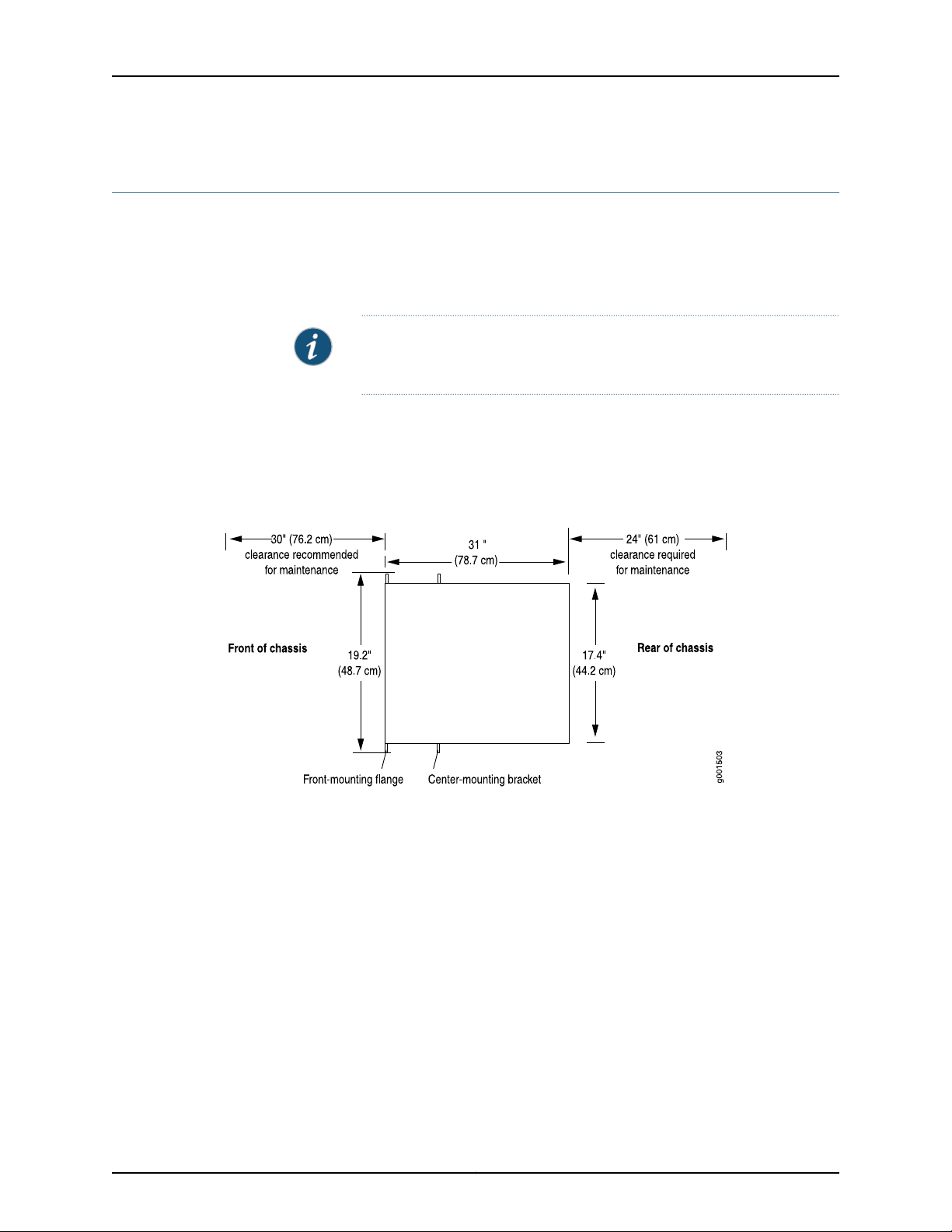
T640 Core Router Hardware Guide
T640 Clearance Requirements for Airflow and Hardware Maintenance
When planning the installation site, you need to allow sufficient clearance around the
rack (see Figure 42 on page 68):
•
For the cooling system to function properly, the airflow around the chassis must be
unrestricted. Figure 39 on page 61 depicts the airflow in the router.
NOTE: If you mount the router in a cabinet, be sure that ventilation is
sufficient to prevent overheating.
•
For service personnel to remove and install hardware components, there must be
adequate space at the front and back of the router. At least 24 in. (61 cm) is required
both in front of and behind the router. NEBS GR-63 recommends that you allow at
least 30 in. (72.6 cm) in front of the rack and 24 in. (61.0 cm) behind the rack.
Figure 42: T640 Chassis Dimensions and Clearance Requirements
Related
Documentation
• T640 Chassis Description on page 13
• T640 Cooling System Description on page 61
• Safety Requirements, Warnings, and Guidelines for Installing the T640 Router on
page 85
• T640 Physical Specifications on page 341
Copyright © 2010, Juniper Networks, Inc.68
Page 99

CHAPTER 5
T640 Router Installation Overview
•
T640 Router Installation Summary on page 69
T640 Router Installation Summary
It is important to proceed through the installation process in the following order:
1. Prepare your installation site.
See “T640 Site Preparation Checklist” on page 65.
2. Review the safety guidelines.
See “General Safety Guidelines for M Series, MX Series, and T Series Routers” on
page 303.
3. Unpack the router and verify the parts received.
“Unpacking the T640 Router” on page 71.
4. Install the mounting hardware.
See “Installing the T640 Mounting Hardware for a Four-Post Rack or Cabinet” on
page 78 or “Installing the T640 Mounting Hardware for an Open-Frame Rack” on
page 81.
5. Install the router.
See “Mounting the T640 Chassis Using a Mechanical Lift” on page 89 or “Installing
the T640 Chassis in the Rack Manually” on page 104.
6. Ground the router.
See “Connecting the T640 Grounding Cable” on page 115.
7. Connect the router to a management device.
See “Connecting the T640 Router to a Management Console or Auxiliary Device” on
page 119.
8. Power on the router.
See “Powering On a DC-Powered T640 Router” on page 130.
9. Perform the initial system configuration.
See “Initially Configuring the T640 Router” on page 139.
69Copyright © 2010, Juniper Networks, Inc.
Page 100

T640 Core Router Hardware Guide
Related
Documentation
• T640 Chassis Description on page 13
• Safety Requirements, Warnings, and Guidelines for Installing the T640 Router on
page 85
• T640 Chassis Lifting Guidelines on page 310
Copyright © 2010, Juniper Networks, Inc.70
 Loading...