

Page 1

SRX345 Services Gateway Hardware Guide
Modified: 2017-09-21
Copyright © 2017, Juniper Networks, Inc.
Page 2

Juniper Networks, Inc.
1133 Innovation Way
Sunnyvale, California 94089
USA
408-745-2000
www.juniper.net
Copyright © 2017 Juniper Networks, Inc. All rights reserved.
Juniper Networks, the Juniper Networks logo, Juniper,and Junos are registered trademarks of Juniper Networks, Inc. and/or its affiliates in
the United States and other countries. All other trademarks may be property of their respective owners.
Juniper Networks assumes no responsibility for any inaccuracies in this document. Juniper Networks reserves the right to change, modify,
transfer, or otherwise revise this publication without notice.
SRX345 Services Gateway Hardware Guide
Copyright © 2017 Juniper Networks, Inc. All rights reserved.
The information in this document is current as of the date on the title page.
YEAR 2000 NOTICE
Juniper Networks hardware and software products are Year 2000 compliant. Junos OS has no known time-related limitationsthrough the
year 2038. However, the NTP application is known to have some difficulty in the year 2036.
END USER LICENSE AGREEMENT
The Juniper Networks product that is the subject of this technical documentation consists of (or is intended for use with) Juniper Networks
software. Use of such software is subject tothe terms and conditions of the End User License Agreement (“EULA”) posted at
http://www.juniper.net/support/eula/. By downloading, installing or using such software, you agree to the terms and conditions of that
EULA.
Copyright © 2017, Juniper Networks, Inc.ii
Page 3

Table of Contents
About the Documentation . . . . . . . . . . . . . . . . . . . . . . . . . . . . . . . . . . . . . . . . . . . . xi
Documentation and Release Notes . . . . . . . . . . . . . . . . . . . . . . . . . . . . . . . . . . xi
Supported Platforms . . . . . . . . . . . . . . . . . . . . . . . . . . . . . . . . . . . . . . . . . . . . . xi
Documentation Conventions . . . . . . . . . . . . . . . . . . . . . . . . . . . . . . . . . . . . . . . xi
Documentation Feedback . . . . . . . . . . . . . . . . . . . . . . . . . . . . . . . . . . . . . . . . xiii
Requesting Technical Support . . . . . . . . . . . . . . . . . . . . . . . . . . . . . . . . . . . . . xiv
Self-Help Online Tools and Resources . . . . . . . . . . . . . . . . . . . . . . . . . . . xiv
Opening a Case with JTAC . . . . . . . . . . . . . . . . . . . . . . . . . . . . . . . . . . . . . xiv
Part 1 Overview
Chapter 1 System Overview . . . . . . . . . . . . . . . . . . . . . . . . . . . . . . . . . . . . . . . . . . . . . . . . . . . 3
SRX345 Services Gateway Description . . . . . . . . . . . . . . . . . . . . . . . . . . . . . . . . . . . 3
Chapter 2 Chassis Description . . . . . . . . . . . . . . . . . . . . . . . . . . . . . . . . . . . . . . . . . . . . . . . . 5
SRX345 Services Gateway Chassis Overview . . . . . . . . . . . . . . . . . . . . . . . . . . . . . . 5
Understanding the SRX345 Services Gateway Front Panel . . . . . . . . . . . . . . . . . . . 5
Understanding the SRX345 Services Gateway Back Panel . . . . . . . . . . . . . . . . . . . 8
Chapter 3 Interface Module Descriptions . . . . . . . . . . . . . . . . . . . . . . . . . . . . . . . . . . . . . . . 11
SRX345 Services Gateway Interface Modules Overview . . . . . . . . . . . . . . . . . . . . . 11
Chapter 4 Cooling System Description . . . . . . . . . . . . . . . . . . . . . . . . . . . . . . . . . . . . . . . . . 13
Understanding the SRX345 Services Gateway Cooling System . . . . . . . . . . . . . . . 13
Chapter 5 Power System Description . . . . . . . . . . . . . . . . . . . . . . . . . . . . . . . . . . . . . . . . . . 15
Understanding the SRX345 Services Gateway Power Supply . . . . . . . . . . . . . . . . 15
Part 2 Site Planning and Specifications
Chapter 6 Planning and Preparing the Site . . . . . . . . . . . . . . . . . . . . . . . . . . . . . . . . . . . . . 19
SRX345 Services Gateway Physical Specifications . . . . . . . . . . . . . . . . . . . . . . . . 19
SRX345 Services Gateway Environmental Specifications . . . . . . . . . . . . . . . . . . . 19
Site Preparation Checklist for the SRX345 Services Gateway . . . . . . . . . . . . . . . . 20
General Site Installation Guidelines for the SRX345 Services Gateway . . . . . . . . 22
Chapter 7 Rack Requirements . . . . . . . . . . . . . . . . . . . . . . . . . . . . . . . . . . . . . . . . . . . . . . . . 25
SRX345 Services Gateway Rack-Mounting Requirements and Warnings . . . . . . . 25
SRX345 Services Gateway Rack Size and Strength Requirements . . . . . . . . . . . . 29
SRX345 Services Gateway Spacing of Mounting Brackets and Flange Holes . . . . 29
SRX345 Services Gateway Clearance Requirements for Airflow and Hardware
Maintenance . . . . . . . . . . . . . . . . . . . . . . . . . . . . . . . . . . . . . . . . . . . . . . . . . . . 30
iiiCopyright © 2017, Juniper Networks, Inc.
Page 4

SRX345 Services Gateway Hardware Guide
Chapter 8 Cabinet Requirements . . . . . . . . . . . . . . . . . . . . . . . . . . . . . . . . . . . . . . . . . . . . . 31
SRX345 Services Gateway Cabinet Size and Clearance Requirements . . . . . . . . . 31
SRX345 Services Gateway Cabinet Airflow Requirements . . . . . . . . . . . . . . . . . . . 31
Chapter 9 Power Requirements and Specifications . . . . . . . . . . . . . . . . . . . . . . . . . . . . . 33
SRX345 Services Gateway Electrical Wiring Guidelines . . . . . . . . . . . . . . . . . . . . . 33
SRX345 Services Gateway Power Specifications and Requirements . . . . . . . . . . 34
SRX345 Services Gateway Supported AC Power Cords . . . . . . . . . . . . . . . . . . . . . 35
Chapter 10 Cable Specifications and Pinouts . . . . . . . . . . . . . . . . . . . . . . . . . . . . . . . . . . . 37
RJ-45 Connector Pinouts for the SRX345 Services Gateway Ethernet Port . . . . . 37
RJ-45 Connector Pinouts for the SRX345 Services Gateway Console Port . . . . . . 37
Mini-USB Connector Pinouts for the SRX345 Services Gateway Console Port . . 38
Part 3 Initial Installation and Configuration
Chapter 11 Installation Overview . . . . . . . . . . . . . . . . . . . . . . . . . . . . . . . . . . . . . . . . . . . . . . 43
SRX345 Services Gateway Installation Overview . . . . . . . . . . . . . . . . . . . . . . . . . . 43
Required Tools and Parts for Installing the SRX345 Services Gateway . . . . . . . . . 43
SRX345 Services Gateway Autoinstallation Overview . . . . . . . . . . . . . . . . . . . . . . 44
Chapter 12 Unpacking the SRX345 Services Gateway . . . . . . . . . . . . . . . . . . . . . . . . . . . . 45
Unpacking the SRX345 Services Gateway . . . . . . . . . . . . . . . . . . . . . . . . . . . . . . . 45
Verifying Parts Received with the SRX345 Services Gateway . . . . . . . . . . . . . . . . 46
Chapter 13 Installing the Rack Mounting Hardware . . . . . . . . . . . . . . . . . . . . . . . . . . . . . . 49
Preparing the SRX345 Services Gateway for Rack-Mount Installation . . . . . . . . . 49
Connecting the SRX345 Services Gateway to the Building Structure . . . . . . . . . . 49
Chapter 14 Installing the SRX345 Services Gateway in a Rack . . . . . . . . . . . . . . . . . . . . . 51
Installing the SRX345 Services Gateway into a Rack . . . . . . . . . . . . . . . . . . . . . . . 51
Chapter 15 Connecting the SRX345 Services Gateway to Ground . . . . . . . . . . . . . . . . . 55
Required Tools and Parts for Grounding the SRX345 Services Gateway . . . . . . . . 55
SRX345 Services Gateway Grounding Specifications . . . . . . . . . . . . . . . . . . . . . . 55
Connecting the SRX345 Services Gateway Grounding Cable . . . . . . . . . . . . . . . . 56
Chapter 16 Connecting the SRX345 Services Gateway to External Devices . . . . . . . . . 59
Connecting the Dial-Up Modem to the Console Port on the SRX345 Services
Connecting to the SRX345 Services Gateway CLI Using a Dial-Up Modem . . . . . 60
Chapter 17 Providing Power to the SRX345 Services Gateway . . . . . . . . . . . . . . . . . . . . 63
Connecting the SRX345 Services Gateway to an AC Power Supply . . . . . . . . . . . 63
Powering On the SRX345 Services Gateway . . . . . . . . . . . . . . . . . . . . . . . . . . . . . 64
Powering Off the SRX345 Services Gateway . . . . . . . . . . . . . . . . . . . . . . . . . . . . . 65
Gateway . . . . . . . . . . . . . . . . . . . . . . . . . . . . . . . . . . . . . . . . . . . . . . . . . . . . . . 59
Copyright © 2017, Juniper Networks, Inc.iv
Page 5

Table of Contents
Chapter 18 Performing the Initial Configuration . . . . . . . . . . . . . . . . . . . . . . . . . . . . . . . . . 67
SRX345 Services Gateway Software Configuration Overview . . . . . . . . . . . . . . . . 67
Understanding SRX345 Services Gateway Factory-Default Settings . . . . . . . . . . 68
Viewing SRX345 Services Gateway Factory-Default Settings . . . . . . . . . . . . . . . . 69
Configuring Zero-Touch Provisioning on the SRX345 Services Gateway . . . . . . . 70
Accessing J-Web on the SRX345 Services Gateway . . . . . . . . . . . . . . . . . . . . . . . . 71
Configuring the SRX345 Services Gateway Using the J-Web Setup Wizard . . . . . 72
About the Setup Wizard . . . . . . . . . . . . . . . . . . . . . . . . . . . . . . . . . . . . . . . . . . 73
About the Default Setup Mode . . . . . . . . . . . . . . . . . . . . . . . . . . . . . . . . . . . . . 73
About the Guided Setup Mode . . . . . . . . . . . . . . . . . . . . . . . . . . . . . . . . . . . . . 74
Accessing the CLI on the SRX345 Services Gateway . . . . . . . . . . . . . . . . . . . . . . . 76
Connecting to the SRX345 Services Gateway from the CLI Remotely . . . . . . . . . . 77
Configuring the SRX345 Services Gateway Using the CLI . . . . . . . . . . . . . . . . . . . 78
Part 4 Maintaining and Troubleshooting Components
Chapter 19 Maintaining Components . . . . . . . . . . . . . . . . . . . . . . . . . . . . . . . . . . . . . . . . . . 85
Required Tools and Parts for Maintaining the SRX345 Services Gateway
Hardware Components . . . . . . . . . . . . . . . . . . . . . . . . . . . . . . . . . . . . . . . . . . 85
Routine Maintenance Procedures for the SRX345 Services Gateway . . . . . . . . . . 85
Maintaining the SRX345 Services Gateway Cooling System Components . . . . . 86
Maintaining the SRX345 Services Gateway Power Supply . . . . . . . . . . . . . . . . . . 86
Chapter 20 Troubleshooting Components . . . . . . . . . . . . . . . . . . . . . . . . . . . . . . . . . . . . . . 89
Troubleshooting Resources for the SRX345 Services Gateway Overview . . . . . . 89
TroubleshootingChassisand InterfaceAlarmMessageson the SRX345 Services
Gateway . . . . . . . . . . . . . . . . . . . . . . . . . . . . . . . . . . . . . . . . . . . . . . . . . . . . . . 90
Troubleshooting the Power System on the SRX345 Services Gateway . . . . . . . . . 91
Using the RESET CONFIG Button on the SRX345 Services Gateway . . . . . . . . . . 92
Changing the RESET CONFIG Button Behavior on the SRX345 Services
Gateway . . . . . . . . . . . . . . . . . . . . . . . . . . . . . . . . . . . . . . . . . . . . . . . . . . . . . . 93
Part 5 Replacing Components
Chapter 21 Overview of Replacing Components . . . . . . . . . . . . . . . . . . . . . . . . . . . . . . . . . 97
SRX345 Services Gateway Field Replaceable Units Overview . . . . . . . . . . . . . . . . 97
Required Tools and Parts for Replacing the SRX345 Services Gateway
Components . . . . . . . . . . . . . . . . . . . . . . . . . . . . . . . . . . . . . . . . . . . . . . . . . . . 97
Chapter 22 Replacing Interface Modules . . . . . . . . . . . . . . . . . . . . . . . . . . . . . . . . . . . . . . . 99
Replacing Mini-Physical Interface Modules in the SRX345 Services Gateway . . . 99
Chapter 23 Contacting Customer Support and Returning Components . . . . . . . . . . . . 101
Contacting Customer Support . . . . . . . . . . . . . . . . . . . . . . . . . . . . . . . . . . . . . . . . 101
Returning a SRX345 Services Gateway Component to Juniper Networks . . . . . . 102
Locating the SRX345 Services Gateway Chassis Serial Number and Agency
Labels . . . . . . . . . . . . . . . . . . . . . . . . . . . . . . . . . . . . . . . . . . . . . . . . . . . . . . . 103
Locating the SRX345 Services Gateway Mini-Physical Interface Module Serial
Number Label . . . . . . . . . . . . . . . . . . . . . . . . . . . . . . . . . . . . . . . . . . . . . . . . . 103
vCopyright © 2017, Juniper Networks, Inc.
Page 6

SRX345 Services Gateway Hardware Guide
Listing the SRX345 Services Gateway Component Details with the CLI . . . . . . . 104
Information You Might Need to Supply to JTAC . . . . . . . . . . . . . . . . . . . . . . . . . . 104
Required Tools and Parts for Packing the SRX345 Services Gateway . . . . . . . . . 105
Packing the SRX345 Services Gateway for Shipment . . . . . . . . . . . . . . . . . . . . . 106
Packing SRX345 Services Gateway Components for Shipment . . . . . . . . . . . . . 107
Part 6 Safety and Regulatory Compliance Information
Chapter 24 General Safety Guidelines and Warnings . . . . . . . . . . . . . . . . . . . . . . . . . . . . . 111
Definitions of Safety Warning Levels . . . . . . . . . . . . . . . . . . . . . . . . . . . . . . . . . . . . 111
General Safety Guidelines and Warnings . . . . . . . . . . . . . . . . . . . . . . . . . . . . . . . . 113
Restricted Access Warning . . . . . . . . . . . . . . . . . . . . . . . . . . . . . . . . . . . . . . . . . . . 114
Qualified Personnel Warning . . . . . . . . . . . . . . . . . . . . . . . . . . . . . . . . . . . . . . . . . . 115
Prevention of Electrostatic Discharge Damage . . . . . . . . . . . . . . . . . . . . . . . . . . . 116
Chapter 25 Fire Safety Requirements . . . . . . . . . . . . . . . . . . . . . . . . . . . . . . . . . . . . . . . . . . 119
Fire Safety Requirements . . . . . . . . . . . . . . . . . . . . . . . . . . . . . . . . . . . . . . . . . . . . 119
Chapter 26 Laser and LED Safety Guidelines and Warnings . . . . . . . . . . . . . . . . . . . . . . . 121
Laser and LED Safety Guidelines and Warnings . . . . . . . . . . . . . . . . . . . . . . . . . . . 121
Radiation from Open Port Apertures Warning . . . . . . . . . . . . . . . . . . . . . . . . . . . . 123
Chapter 27 Maintenance and Operational Safety Guidelines and Warnings . . . . . . . . 125
Maintenance and Operational Safety Guidelines and Warnings . . . . . . . . . . . . . 125
Chapter 28 Electrical Safety Guidelines and Warnings . . . . . . . . . . . . . . . . . . . . . . . . . . . 131
Action to Take After an Electrical Accident . . . . . . . . . . . . . . . . . . . . . . . . . . . . . . . 131
General Electrical Safety Guidelines and Warnings . . . . . . . . . . . . . . . . . . . . . . . . 131
AC Power Electrical Safety Guidelines . . . . . . . . . . . . . . . . . . . . . . . . . . . . . . . . . . 132
Chapter 29 Agency Approvals and Regulatory Compliance Information . . . . . . . . . . . . 135
SRX345 Services Gateway Agency Approvals . . . . . . . . . . . . . . . . . . . . . . . . . . . . 135
SRX345 Services Gateway Acoustic Noise Compliance Statements . . . . . . . . . 136
SRX345 Services Gateway EMC Requirements . . . . . . . . . . . . . . . . . . . . . . . . . . . 137
General Laser Safety Guidelines . . . . . . . . . . . . . . . . . . . . . . . . . . . . . . . . . . . 121
Class 1 Laser Product Warning . . . . . . . . . . . . . . . . . . . . . . . . . . . . . . . . . . . . . 122
Class 1 LED Product Warning . . . . . . . . . . . . . . . . . . . . . . . . . . . . . . . . . . . . . . 122
Laser Beam Warning . . . . . . . . . . . . . . . . . . . . . . . . . . . . . . . . . . . . . . . . . . . . 122
Battery Handling Warning . . . . . . . . . . . . . . . . . . . . . . . . . . . . . . . . . . . . . . . . 125
Jewelry Removal Warning . . . . . . . . . . . . . . . . . . . . . . . . . . . . . . . . . . . . . . . . 126
Lightning Activity Warning . . . . . . . . . . . . . . . . . . . . . . . . . . . . . . . . . . . . . . . . 127
Operating Temperature Warning . . . . . . . . . . . . . . . . . . . . . . . . . . . . . . . . . . 128
Product Disposal Warning . . . . . . . . . . . . . . . . . . . . . . . . . . . . . . . . . . . . . . . . 129
Canada . . . . . . . . . . . . . . . . . . . . . . . . . . . . . . . . . . . . . . . . . . . . . . . . . . . . . . . 137
European Community . . . . . . . . . . . . . . . . . . . . . . . . . . . . . . . . . . . . . . . . . . . 137
Israel . . . . . . . . . . . . . . . . . . . . . . . . . . . . . . . . . . . . . . . . . . . . . . . . . . . . . . . . . 137
Japan . . . . . . . . . . . . . . . . . . . . . . . . . . . . . . . . . . . . . . . . . . . . . . . . . . . . . . . . 137
United States . . . . . . . . . . . . . . . . . . . . . . . . . . . . . . . . . . . . . . . . . . . . . . . . . . 137
Copyright © 2017, Juniper Networks, Inc.vi
Page 7

List of Figures
Part 1 Overview
Chapter 1 System Overview . . . . . . . . . . . . . . . . . . . . . . . . . . . . . . . . . . . . . . . . . . . . . . . . . . . 3
Figure 1: SRX345 Services Gateway . . . . . . . . . . . . . . . . . . . . . . . . . . . . . . . . . . . . . . 3
Chapter 2 Chassis Description . . . . . . . . . . . . . . . . . . . . . . . . . . . . . . . . . . . . . . . . . . . . . . . . 5
Figure 2: SRX345 Services Gateway (Single AC Power Supply) Front Panel . . . . . 6
Figure 3: SRX345 Services Gateway (Dual AC Power Supplies) Front Panel . . . . . 6
Figure 4: SRX345 Services Gateway Front Panel LEDs . . . . . . . . . . . . . . . . . . . . . . . 7
Figure 5: SRX345 Services Gateway Back Panel (Single AC Power Supply) . . . . . . 8
Figure 6: SRX345 Services Gateway Back Panel (Dual AC Power Supplies) . . . . . 8
Chapter 4 Cooling System Description . . . . . . . . . . . . . . . . . . . . . . . . . . . . . . . . . . . . . . . . . 13
Figure 7: Airflow Through the SRX345 Services Gateway Chassis . . . . . . . . . . . . . 13
Part 2 Site Planning and Specifications
Chapter 9 Power Requirements and Specifications . . . . . . . . . . . . . . . . . . . . . . . . . . . . . 33
Figure 8: AC Plug Types . . . . . . . . . . . . . . . . . . . . . . . . . . . . . . . . . . . . . . . . . . . . . . 35
Part 3 Initial Installation and Configuration
Chapter 14 Installing the SRX345 Services Gateway in a Rack . . . . . . . . . . . . . . . . . . . . . 51
Figure 9: Installing the Rack Mount Brackets (Front Mount Position) . . . . . . . . . . 51
Figure 10: Installing the Rack Mount Brackets (Center Mount Position) . . . . . . . . 52
Figure 11: Installing the Services Gatewayin the Rack (Front Mount Shown, Center
Mount Similar) . . . . . . . . . . . . . . . . . . . . . . . . . . . . . . . . . . . . . . . . . . . . . . . . . 52
Chapter 15 Connecting the SRX345 Services Gateway to Ground . . . . . . . . . . . . . . . . . 55
Figure 12: Connecting the Grounding Cable to the SRX345 Services Gateway . . . 57
Chapter 17 Providing Power to the SRX345 Services Gateway . . . . . . . . . . . . . . . . . . . . 63
Figure 13: Connecting the SRX345 Services Gateway to an AC Power Supply . . . 64
Chapter 18 Performing the Initial Configuration . . . . . . . . . . . . . . . . . . . . . . . . . . . . . . . . . 67
Figure 14: Connecting to the Management Port on the SRX345 Services
Gateway . . . . . . . . . . . . . . . . . . . . . . . . . . . . . . . . . . . . . . . . . . . . . . . . . . . . . . . 72
Figure 15: Connecting to the Console Port on the SRX345 Services Gateway . . . . 77
Part 6 Safety and Regulatory Compliance Information
Chapter 24 General Safety Guidelines and Warnings . . . . . . . . . . . . . . . . . . . . . . . . . . . . . 111
Figure 16: Placing a Component into an Antistatic Bag . . . . . . . . . . . . . . . . . . . . . 117
viiCopyright © 2017, Juniper Networks, Inc.
Page 8

SRX345 Services Gateway Hardware Guide
Copyright © 2017, Juniper Networks, Inc.viii
Page 9

List of Tables
About the Documentation . . . . . . . . . . . . . . . . . . . . . . . . . . . . . . . . . . . . . . . . . . xi
Table 1: Notice Icons . . . . . . . . . . . . . . . . . . . . . . . . . . . . . . . . . . . . . . . . . . . . . . . . . xii
Table 2: Text and Syntax Conventions . . . . . . . . . . . . . . . . . . . . . . . . . . . . . . . . . . . xii
Part 1 Overview
Chapter 2 Chassis Description . . . . . . . . . . . . . . . . . . . . . . . . . . . . . . . . . . . . . . . . . . . . . . . . 5
Table 3: SRX345 Services Gateway Front Panel Components . . . . . . . . . . . . . . . . 6
Table 4: SRX345 Services Gateway Front Panel LEDs . . . . . . . . . . . . . . . . . . . . . . . 7
Table 5: SRX345 Services Gateway Back Panel Components . . . . . . . . . . . . . . . . . 9
Table 6: SRX345 Services Gateway (with Dual AC Power Supplies) Back Panel
Part 2 Site Planning and Specifications
Chapter 6 Planning and Preparing the Site . . . . . . . . . . . . . . . . . . . . . . . . . . . . . . . . . . . . . 19
Table 7: Physical Specifications for the SRX345 Services Gateway . . . . . . . . . . . . 19
Table 8: Environmental Specifications for the SRX345 Services Gateway . . . . . . 20
Table 9: Site Preparation Checklist for SRX345 Services Gateway
Chapter 9 Power Requirements and Specifications . . . . . . . . . . . . . . . . . . . . . . . . . . . . . 33
Table 10: Site Electrical Wiring Guidelines for the SRX345 Services Gateway . . . 33
Table 11: Power System Electrical Specifications for the SRX345 Services
Table 12: AC Power Cord Specifications . . . . . . . . . . . . . . . . . . . . . . . . . . . . . . . . . 35
Chapter 10 Cable Specifications and Pinouts . . . . . . . . . . . . . . . . . . . . . . . . . . . . . . . . . . . 37
Table 13: RJ-45 Connector Pinouts for the SRX345 Services Gateway Ethernet
Table 14: RJ-45 Connector Pinouts for the SRX345 Services Gateway Console
Table15: Mini-USB Type-BConnectorPinouts for the Services Gateway Console
LEDs . . . . . . . . . . . . . . . . . . . . . . . . . . . . . . . . . . . . . . . . . . . . . . . . . . . . . . . . . . 9
Installation . . . . . . . . . . . . . . . . . . . . . . . . . . . . . . . . . . . . . . . . . . . . . . . . . . . . 20
Gateway (AC Models) . . . . . . . . . . . . . . . . . . . . . . . . . . . . . . . . . . . . . . . . . . . 34
Port . . . . . . . . . . . . . . . . . . . . . . . . . . . . . . . . . . . . . . . . . . . . . . . . . . . . . . . . . . 37
Port . . . . . . . . . . . . . . . . . . . . . . . . . . . . . . . . . . . . . . . . . . . . . . . . . . . . . . . . . . 38
Port . . . . . . . . . . . . . . . . . . . . . . . . . . . . . . . . . . . . . . . . . . . . . . . . . . . . . . . . . . 38
Part 3 Initial Installation and Configuration
Chapter 12 Unpacking the SRX345 Services Gateway . . . . . . . . . . . . . . . . . . . . . . . . . . . . 45
Table 16: Parts List for a Fully Configured SRX345 Services Gateway . . . . . . . . . . 46
Table 17: Accessory Parts List for the SRX345 Services Gateway . . . . . . . . . . . . . 47
Chapter 15 Connecting the SRX345 Services Gateway to Ground . . . . . . . . . . . . . . . . . 55
ixCopyright © 2017, Juniper Networks, Inc.
Page 10

SRX345 Services Gateway Hardware Guide
Table 18: Grounding Cable Specifications for the Services Gateway . . . . . . . . . . . 56
Chapter 18 Performing the Initial Configuration . . . . . . . . . . . . . . . . . . . . . . . . . . . . . . . . . 67
Table 19: Default Interface Configuration for the SRX345 Services Gateway . . . . 68
Part 4 Maintaining and Troubleshooting Components
Chapter 20 Troubleshooting Components . . . . . . . . . . . . . . . . . . . . . . . . . . . . . . . . . . . . . . 89
Table 20: SRX345 Services Gateway Chassis Alarm Conditions and Corrective
Table 21: SRX345 Services Gateway Power LED Status . . . . . . . . . . . . . . . . . . . . . 91
Actions . . . . . . . . . . . . . . . . . . . . . . . . . . . . . . . . . . . . . . . . . . . . . . . . . . . . . . . 90
Copyright © 2017, Juniper Networks, Inc.x
Page 11

About the Documentation
•
Documentation and Release Notes on page xi
•
Supported Platforms on page xi
•
Documentation Conventions on page xi
•
Documentation Feedback on page xiii
•
Requesting Technical Support on page xiv
Documentation and Release Notes
To obtain the most current version of all Juniper Networks®technical documentation,
see the product documentation page on the Juniper Networks website at
http://www.juniper.net/techpubs/.
If the information in the latest release notes differs from the information in the
documentation, follow the product Release Notes.
Juniper Networks Books publishes books by Juniper Networks engineers and subject
matter experts. These books go beyond the technical documentation to explore the
nuances of network architecture, deployment, and administration. The current list can
be viewed at http://www.juniper.net/books.
Supported Platforms
For the features described in this document, the following platforms are supported:
•
SRX345
Documentation Conventions
Table 1 on page xii defines notice icons used in this guide.
xiCopyright © 2017, Juniper Networks, Inc.
Page 12
SRX345 Services Gateway Hardware Guide
Table 1: Notice Icons
DescriptionMeaningIcon
Indicates important features or instructions.Informational note
Indicates a situation that might result in loss of data or hardware damage.Caution
Alerts you to the risk of personal injury or death.Warning
Alerts you to the risk of personal injury from a laser.Laser warning
Indicates helpful information.Tip
Table 2 on page xii defines the text and syntax conventions used in this guide.
Table 2: Text and Syntax Conventions
Represents text that you type.Bold text like this
Fixed-width text like this
Italic text like this
Italic text like this
Represents output that appears on the
terminal screen.
•
Introduces or emphasizes important
new terms.
•
Identifies guide names.
•
Identifies RFC and Internet draft titles.
Represents variables (options for which
you substitute a value) in commands or
configuration statements.
Alerts you to a recommended use or implementation.Best practice
ExamplesDescriptionConvention
To enter configuration mode, type the
configure command:
user@host> configure
user@host> show chassis alarms
No alarms currently active
•
A policy term is a named structure
that defines match conditions and
actions.
•
Junos OS CLI User Guide
•
RFC 1997,BGP Communities Attribute
Configure the machine’s domain name:
[edit]
root@# set system domain-name
domain-name
Copyright © 2017, Juniper Networks, Inc.xii
Page 13

Table 2: Text and Syntax Conventions (continued)
Text like this
Represents names of configuration
statements, commands, files, and
directories;configuration hierarchy levels;
or labels on routing platform
components.
About the Documentation
ExamplesDescriptionConvention
•
To configure a stub area, include the
stub statement at the [edit protocols
ospf area area-id] hierarchy level.
•
The consoleport is labeledCONSOLE.
stub <default-metric metric>;Encloses optional keywords or variables.< > (angle brackets)
| (pipe symbol)
# (pound sign)
[ ] (square brackets)
Indention and braces ( { } )
; (semicolon)
GUI Conventions
Bold text like this
Indicatesa choice between the mutually
exclusivekeywordsor variables on either
side of the symbol. The set of choices is
often enclosed in parentheses for clarity.
same line as the configuration statement
to which it applies.
Encloses a variable for which you can
substitute one or more values.
Identifies a level in the configuration
hierarchy.
Identifies a leaf statement at a
configuration hierarchy level.
Representsgraphicaluser interface(GUI)
items you click or select.
broadcast | multicast
(string1 | string2 | string3)
rsvp { # Required for dynamic MPLS onlyIndicates a comment specified on the
community name members [
community-ids ]
[edit]
routing-options {
static {
route default {
nexthop address;
retain;
}
}
}
•
In the Logical Interfaces box, select
All Interfaces.
•
To cancel the configuration, click
Cancel.
> (bold right angle bracket)
Documentation Feedback
We encourage you to provide feedback, comments, and suggestions so that we can
improve the documentation. You can provide feedback by using either of the following
methods:
•
Online feedback rating system—On any page of the Juniper Networks TechLibrary site
at http://www.juniper.net/techpubs/index.html,simply click the stars to ratethe content,
and use the pop-up form to provide us with information about your experience.
Alternately, you can use the online feedback form at
http://www.juniper.net/techpubs/feedback/.
Separates levels in a hierarchy of menu
selections.
In the configuration editor hierarchy,
select Protocols>Ospf.
xiiiCopyright © 2017, Juniper Networks, Inc.
Page 14

SRX345 Services Gateway Hardware Guide
•
E-mail—Sendyourcomments to techpubs-comments@juniper.net.Includethe document
or topic name, URL or page number, and software version (if applicable).
Requesting Technical Support
Technicalproduct support is available through the Juniper Networks TechnicalAssistance
Center (JTAC). If you are a customer with an active J-Care or Partner Support Service
support contract, or are covered under warranty, and need post-sales technical support,
you can access our tools and resources online or open a case with JTAC.
•
JTAC policies—For a complete understanding of our JTAC procedures and policies,
review the JTAC User Guide located at
http://www.juniper.net/us/en/local/pdf/resource-guides/7100059-en.pdf.
•
Product warranties—For product warranty information, visit
http://www.juniper.net/support/warranty/.
•
JTAC hours of operation—The JTAC centers have resources available 24 hours a day,
7 days a week, 365 days a year.
Self-Help Online Tools and Resources
For quick and easy problem resolution, Juniper Networks has designed an online
self-service portal called the Customer Support Center (CSC) that provides you with the
following features:
•
Find CSC offerings: http://www.juniper.net/customers/support/
•
Search for known bugs: https://prsearch.juniper.net/
•
Find product documentation: http://www.juniper.net/documentation/
•
Find solutions and answer questions using our Knowledge Base: http://kb.juniper.net/
•
Download the latest versions of software and review release notes:
http://www.juniper.net/customers/csc/software/
•
Search technical bulletins for relevant hardware and software notifications:
http://kb.juniper.net/InfoCenter/
•
Join and participate in the Juniper Networks Community Forum:
http://www.juniper.net/company/communities/
•
Open a case online in the CSC Case Management tool: http://www.juniper.net/cm/
Toverify service entitlement by product serial number, use our Serial Number Entitlement
(SNE) Tool: https://entitlementsearch.juniper.net/entitlementsearch/
Opening a Case with JTAC
You can open a case with JTAC on the Web or by telephone.
•
Use the Case Management tool in the CSC at http://www.juniper.net/cm/.
•
Call 1-888-314-JTAC (1-888-314-5822 toll-free in the USA, Canada, and Mexico).
Copyright © 2017, Juniper Networks, Inc.xiv
Page 15

About the Documentation
For international or direct-dial options in countries without toll-free numbers, see
http://www.juniper.net/support/requesting-support.html.
xvCopyright © 2017, Juniper Networks, Inc.
Page 16

SRX345 Services Gateway Hardware Guide
Copyright © 2017, Juniper Networks, Inc.xvi
Page 17

PART 1
Overview
•
System Overview on page 3
•
Chassis Description on page 5
•
Interface Module Descriptions on page 11
•
Cooling System Description on page 13
•
Power System Description on page 15
1Copyright © 2017, Juniper Networks, Inc.
Page 18

SRX345 Services Gateway Hardware Guide
Copyright © 2017, Juniper Networks, Inc.2
Page 19
CHAPTER 1
g006765
System Overview
•
SRX345 Services Gateway Description on page 3
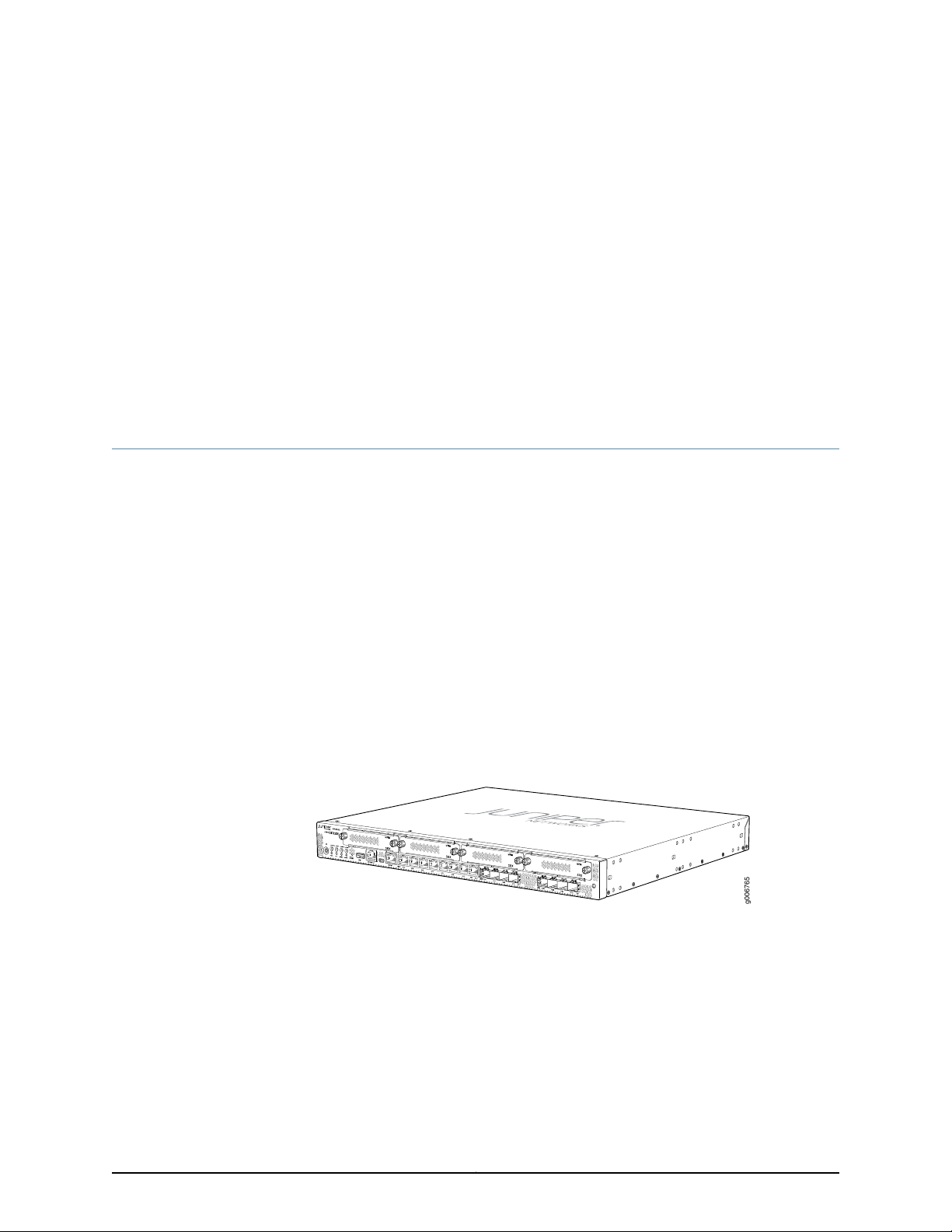
SRX345 Services Gateway Description
The SRX345 Services Gateway consolidates security, routing, switching, and WAN
interfaces for midsize distributed enterprises. With advancedthreatmitigationcapabilities,
the services gateway provides cost-effective and secure connectivity across distributed
enterprises. The services gateway simplifies network complexity, protects and prioritizes
network resources, and improves user and application experience.
The SRX345 Services Gateway has a capacity of 5 gigabits per second (Gbps) and is 1
rack unit (U) tall. The services gateway has eight 1 G Ethernet ports, eight 1 G SFP ports,
one management port, 4 GB of DRAM memory, 8 GB of flash memory, and four
Mini-PhysicalInterfaceModule(Mini-PIM) slots.The chassis installs in standard 800–mm
(or larger) enclosed cabinets, 19 in. equipment racks,or telecommunicationsopen-frame
racks.
Figure 1 on page 3 shows the SRX345 Services Gateway.
Figure 1: SRX345 Services Gateway
The SRX345 ServicesGateway runs the Junos operating system(Junos OS). The following
are a few of the features supported:
•
Firewall support with key features such as VPN
•
Intrusion Detection and Prevention (IDP), AppSecure, and UTM
•
High availability
•
QoS
•
MPLS
3Copyright © 2017, Juniper Networks, Inc.
Page 20

SRX345 Services Gateway Hardware Guide
•
SkyATP
•
MACsec support on all the ports (starting from Junos OS Release 15.1X49-D100)
•
LTE support (starting from Junos OS Release 15.1X49-D100)
•
Zero Touch Provisioning (starting from Junos OS Release 15.1X49-D100)
For more information on the features supported on SRX345 Services Gateways, see
Feature Explorer.
You can manage the SRX345 Services Gateway by using the same interfaces that you
use for managing other devices running Junos OS—the CLI, the J-Webgraphical interface,
and Junos Space.
The SRX345 Services Gateway is available with either a single AC power supply (Junos
OS Release 15.1X49-D35 and later) or dual AC power supplies (Junos OS Release
15.1X49-D110 and later).
Related
Documentation
• SRX345 Services Gateway Chassis Overview on page 5
• Understanding the SRX345 Services Gateway Front Panel on page 5
• Understanding the SRX345 Services Gateway Back Panel on page 8
Copyright © 2017, Juniper Networks, Inc.4
Page 21

CHAPTER 2
Chassis Description
•
SRX345 Services Gateway Chassis Overview on page 5
•
Understanding the SRX345 Services Gateway Front Panel on page 5
•
Understanding the SRX345 Services Gateway Back Panel on page 8
SRX345 Services Gateway Chassis Overview
The SRX345 Services Gateway chassis is a rigid sheet metal structure that houses all of
the other services gateway components. The chassis installs in standard 800–mm (or
larger) enclosed cabinets, 19 in. equipment racks, or telecommunications open-frame
racks.
CAUTION: Beforeremovingor installing components of a functioning services
gateway, attach an electrostatic discharge (ESD) strap to an ESD point and
place the other end of the straparound your bare wrist. Failureto use an ESD
strap could result in damage to the device.
The services gateway must be connected to earth ground during normal operation. The
protectiveearthing terminal on the side of the chassis is provided to connect the services
gateway to ground.
Related
Documentation
Understanding the SRX345 Services Gateway Front Panel on page 5•
• Understanding the SRX345 Services Gateway Back Panel on page 8
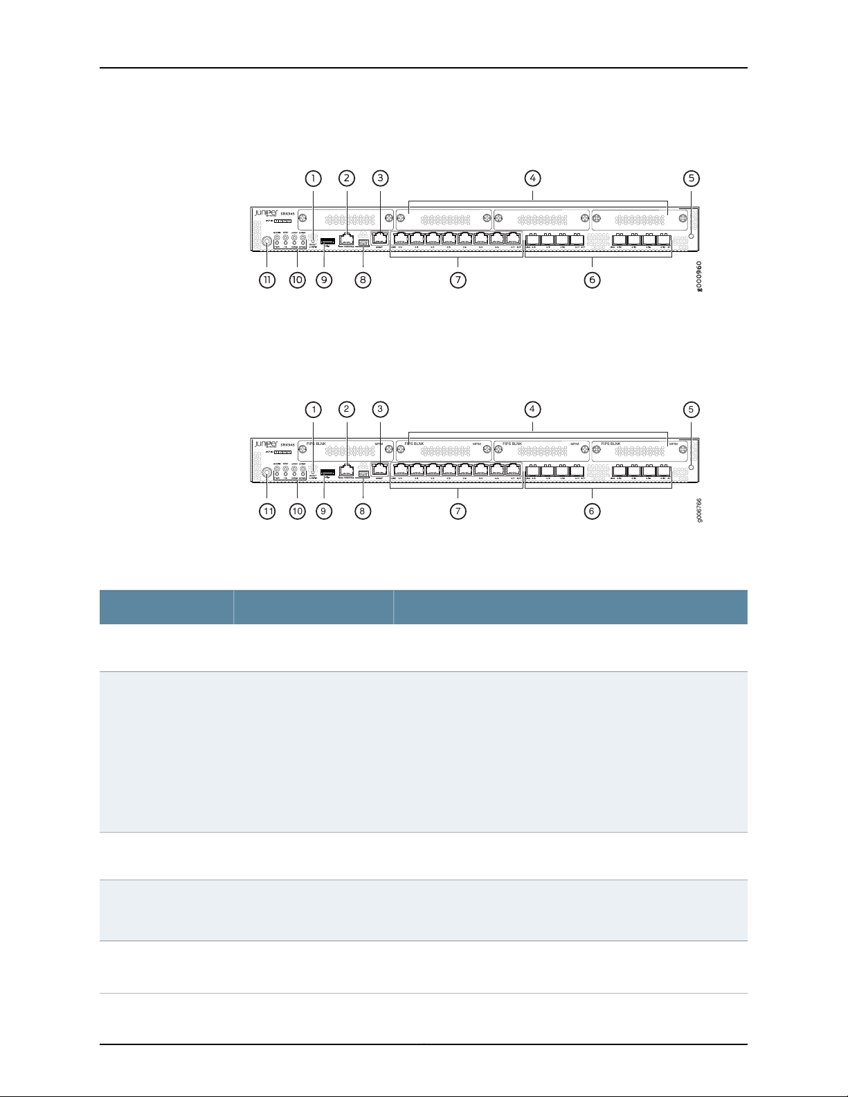
Understanding the SRX345 Services Gateway Front Panel
Figure 2 on page 6 shows the front panel of the SRX345 Services Gateway with a single
AC power supply.
5Copyright © 2017, Juniper Networks, Inc.
Page 22
g006766
6791011 8
2
1
43
5
FIPS BLNK MPIM FIPS BLNK MPIM FIPS BLNK MPIM FIPS BLNK MPIM
SRX345 Services Gateway Hardware Guide
Figure 2: SRX345 Services Gateway(Single AC PowerSupply)Front Panel
Figure 3 on page 6 shows the front panel of the SRX345 Services Gateway with dual
AC power supplies.
Figure 3: SRX345 Services Gateway (Dual AC Power Supplies) Front
Panel
Table 3 on page 6 provides details about the front panel components.
Table 3: SRX345 Services Gateway Front Panel Components
DescriptionComponentCallout
Reset Config button1
Console ports2, 8
Management port3
Mini-PIM slots4
Returns the services gateway to the rescue configuration or the
factory-default configuration.
•
Serial—Connects a laptop to the services gateway for CLI
management. The port uses an RJ-45 serial connection and
supports the RS-232 (EIA-232) standard.
•
USB—Connects a laptop to the services gateway for CLI
management through a USB interface. The port accepts a Mini-B
type USB cable plug. A USB cable with Mini-B and Type A USB
plugs is supplied with the services gateway. To use the mini-USB
consoleport, you must downloada USB driver to the management
device from the SRX345 Software Download page or Silicon
Labs page.
Use the management (MGMT) port to connect to the device over
the network.
Four slots for Mini-PIMs. The Mini-PIM slots can be used to provide
LAN and WANfunctionality along with connectivity to various media
types.
ESD point5
For personal safety, while working on the services gateway, use the
ESD outlet to plug in an ESD grounding strap to prevent your body
from sending static charges to the services gateway.
Copyright © 2017, Juniper Networks, Inc.6
Page 23
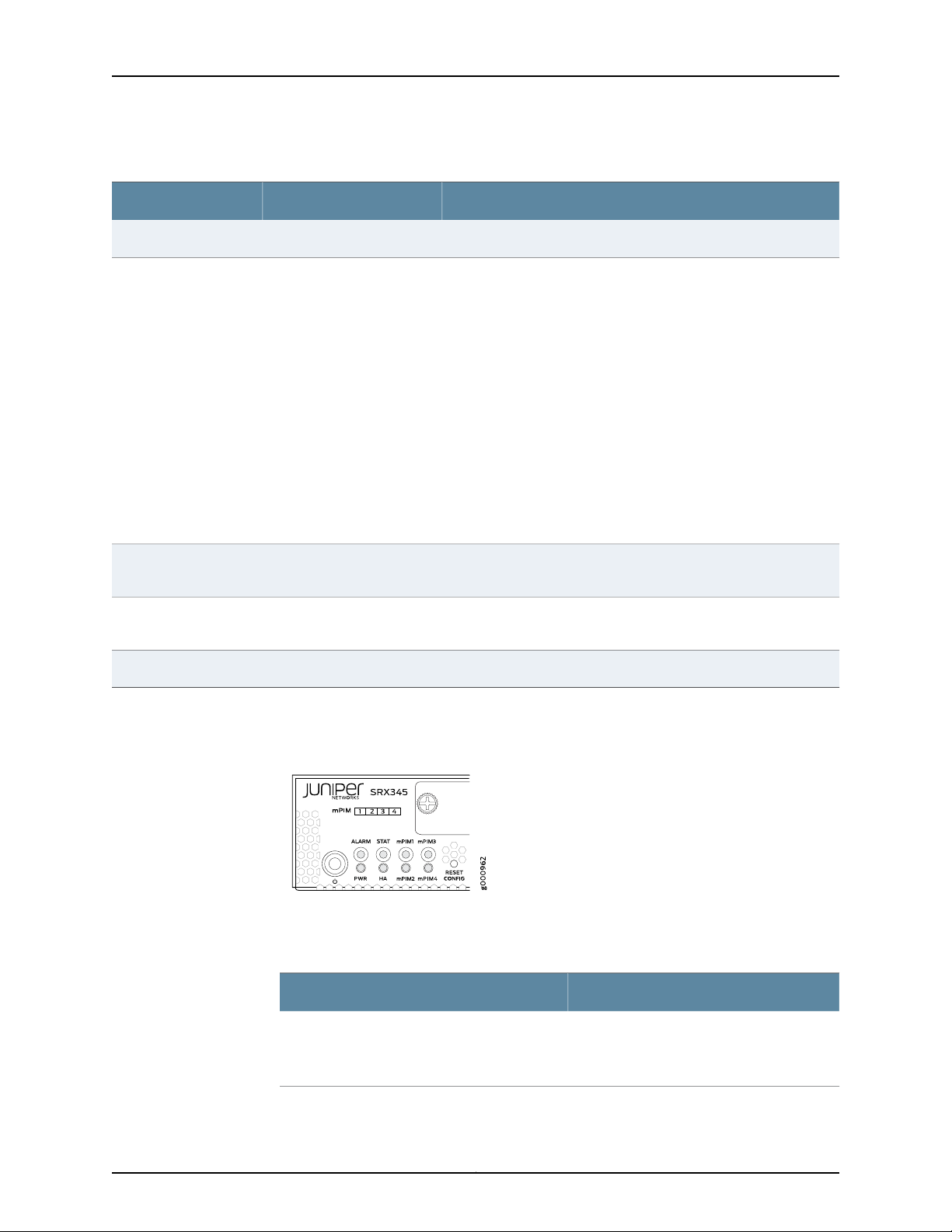
Table 3: SRX345 Services Gateway Front Panel Components (continued)
DescriptionComponentCallout
Eight 1 G small form-factorpluggable (SFP) ports for network traffic.1 G SFP ports6
Chapter 2: Chassis Description
1 G Ethernet ports7
Eight Gigabit Ethernet LAN ports (0/0 to 0/7)
The Gigabit Ethernet ports have the following characteristics:
•
Use an RJ-45 connector
•
Operate in full-duplex and half-duplex modes
•
Support flow control
•
Support autonegotiation
The Gigabit Ethernet ports can be used to:
•
Function as front-end network ports
•
ProvideLAN and WAN connectivity to hubs, switches, local servers,
and workstations
•
Forward incoming data packets to the services gateway
•
Receive outgoing data packets from the services gateway
USB port9
The services gateway has one USB port that accepts a USB storage
device.
LEDs10
Indicate component and system status, and troubleshooting
information at a glance.
Use the Power button to shut down the services gateway.Power button11
Figure 4 on page 7 shows the LEDs on the front panel.
Figure 4: SRX345 Services Gateway Front Panel LEDs
Table 4 on page 7 lists the front panel LEDs.
Table 4: SRX345 Services Gateway Front Panel LEDs
DescriptionComponent
•
ALARM
Solid amber (noncritical alarm)
•
Solid red (critical alarm)
•
Off (no alarms)
7Copyright © 2017, Juniper Networks, Inc.
Page 24
g000961
2
1
3
SRX345 Services Gateway Hardware Guide
Table 4: SRX345 Services Gateway Front Panel LEDs (continued)
STAT
PWR
HA
mPIM1 , mPIM2, mPIM3, and mPIM4
DescriptionComponent
•
Solid green (operating normally)
•
Solid red (error detected)
•
Solid green (receiving power)
•
Solid amber (Power-off triggered)
•
Off (no power)
•
Solid green (all HA links are available)
•
Solid amber (some HA links are
unavailable)
•
Solid red (HA links are not functional)
•
Off (HA is disabled)
•
Solid green (Mini-PIM is functioning
normally)
•
Solid red (Mini-PIM hardware failure)
•
Off (Mini-PIM is not present or Mini-PIM is
not detected by the device)
Related
Documentation
SRX345 Services Gateway Chassis Overview on page 5•
• Understanding the SRX345 Services Gateway Back Panel on page 8
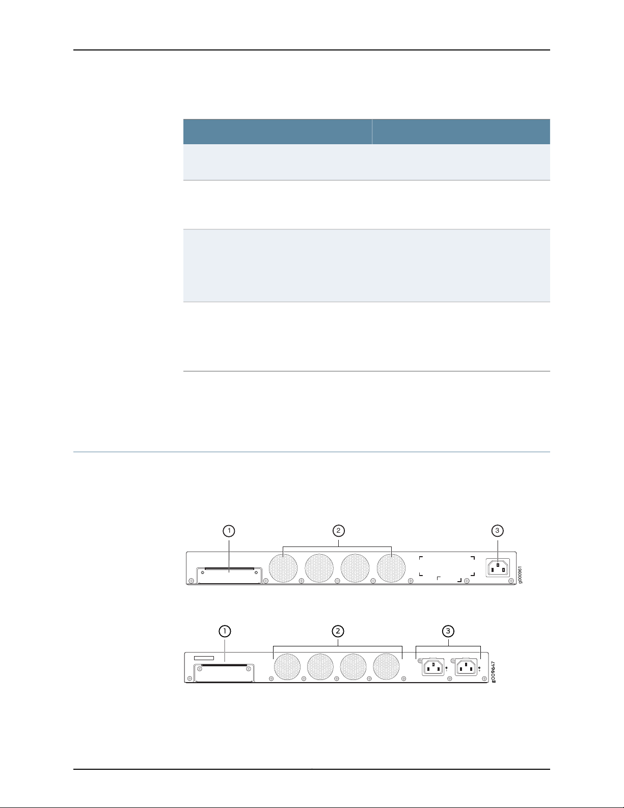
Understanding the SRX345 Services Gateway Back Panel
Figure 5 on page 8 and Figure 6 on page 8 show the back panel of the SRX345 Services
Gateway with a single AC power supply and dual AC power supplies respectively.
Figure 5: SRX345 Services GatewayBack Panel (Single AC Power Supply)
Figure 6: SRX345 Services GatewayBack Panel (Dual AC Power Supplies)
Table 5 on page 9 lists the components on the back panel.
Copyright © 2017, Juniper Networks, Inc.8
Page 25

Chapter 2: Chassis Description
Table 5: SRX345 Services Gateway Back Panel Components
DescriptionComponentCallout
SSD slot1
Fans2
Power supply input3
SSD storage device slot for
optional logging device.
Keeps all the services
gateway components within
the acceptable temperature
range.
Connects the services
gateway to the AC power
supply.
Table 6 on page 9 describes the LEDs on the AC power supplies for the SRX345 Services
Gateway with dual AC power supplies.
Table 6: SRX345 Services Gateway (with Dual AC Power Supplies) Back Panel LEDs
DescriptionLED Color
Receiving powerGreen
No powerOff
Related
Documentation
• SRX345 Services Gateway Chassis Overview on page 5
• Understanding the SRX345 Services Gateway Front Panel on page 5
9Copyright © 2017, Juniper Networks, Inc.
Page 26

SRX345 Services Gateway Hardware Guide
Copyright © 2017, Juniper Networks, Inc.10
Page 27
CHAPTER 3
Interface Module Descriptions
•
SRX345 Services Gateway Interface Modules Overview on page 11
SRX345 Services Gateway Interface Modules Overview
Mini-Physical Interface Modules (Mini-PIMs) are field-replaceable network interface
cards (NICs) supported on the SRX300 line of services gateways. You can easily insert
or remove Mini-PIMs from the front slots of the services gateway chassis. The Mini-PIMs
providephysical connections to a LAN or a WAN.The Mini-PIMs receive incoming packets
from the network and transmit outgoing packets to the network. During this process,
they perform framing and line-speed signaling for the medium type.
CAUTION: The Mini-PIMs are not hot-swappable. You must power off the
services gateway before removing or installing Mini-PIMs.
The following Mini-PIMs are supported on the SRX345 Services Gateway:
Related
Documentation
•
1-Port Serial Mini-Physical Interface Module (SRX-MP-1SERIAL-R)
•
1-Port T1/E1 Mini-Physical Interface Module (SRX-MP-1T1E1-R)
•
1-Port VDSL2 (Annex A) Mini-Physical Interface Module (SRX-MP-1VDSL2-R)
•
LTE Mini-Physical Interface Module (SRX-MP-LTE-AE and SRX-MP-LTE-AA)
NOTE: Gigabit-Backplane Physical Interface Modules (GPIMs) are not
supported on the SRX345 Services Gateway.
For more information on the Mini-PIMs, see SRX300 Series and SRX550 High Memory
Gateway Interface Modules Reference.
• SRX345 Services Gateway Chassis Overview on page 5
• Understanding the SRX345 Services Gateway Front Panel on page 5
11Copyright © 2017, Juniper Networks, Inc.
Page 28

SRX345 Services Gateway Hardware Guide
Copyright © 2017, Juniper Networks, Inc.12
Page 29
CHAPTER 4
Cooling System Description
•
Understanding the SRX345 Services Gateway Cooling System on page 13
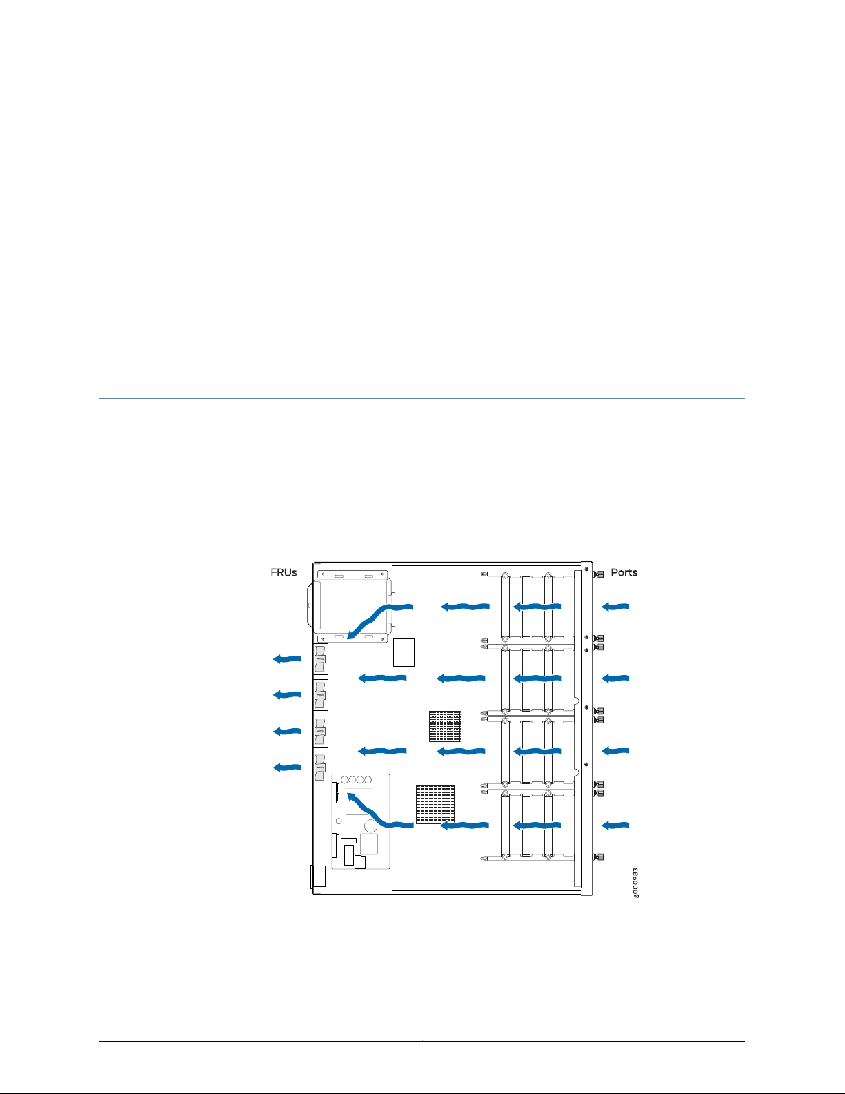
Understanding the SRX345 Services Gateway Cooling System
The cooling system for the SRX345 Services Gateway includes four fixed fans. The fans
draw air through vents on the front of the chassis and exhaust the air through the back
of the chassis. The airflow produced by the fans keeps device components within the
acceptable temperature range.
Figure 7 on page 13 shows the airflow through the SRX345 Services Gateway chassis.
Figure 7: Airflow Through the SRX345 Services Gateway Chassis
Related
Documentation
• SRX345 Services Gateway Chassis Overview on page 5
• Understanding the SRX345 Services Gateway Front Panel on page 5
13Copyright © 2017, Juniper Networks, Inc.
Page 30

SRX345 Services Gateway Hardware Guide
• Understanding the SRX345 Services Gateway Back Panel on page 8
Copyright © 2017, Juniper Networks, Inc.14
Page 31

CHAPTER 5
Power System Description
•
Understanding the SRX345 Services Gateway Power Supply on page 15
Understanding the SRX345 Services Gateway Power Supply
The SRX345 Services Gateway uses a fixed, internal AC power supply. The power supply
distributes the different output voltages to the device components according to their
voltage requirements. The power supply is fixed in the chassis and is not field-replaceable.
The power supply has a single AC appliance inlet that requires a dedicated AC power
feed.
NOTE: Theservices gatewayis available with either a single AC power supply
or dual AC power supplies.
Related
Documentation
• SRX345 Services Gateway Chassis Overview on page 5
• Understanding the SRX345 Services Gateway Front Panel on page 5
• Understanding the SRX345 Services Gateway Back Panel on page 8
• SRX345 Services Gateway Power Specifications and Requirements on page 34
15Copyright © 2017, Juniper Networks, Inc.
Page 32

SRX345 Services Gateway Hardware Guide
Copyright © 2017, Juniper Networks, Inc.16
Page 33

PART 2
Site Planning and Specifications
•
Planning and Preparing the Site on page 19
•
Rack Requirements on page 25
•
Cabinet Requirements on page 31
•
Power Requirements and Specifications on page 33
•
Cable Specifications and Pinouts on page 37
17Copyright © 2017, Juniper Networks, Inc.
Page 34

SRX345 Services Gateway Hardware Guide
Copyright © 2017, Juniper Networks, Inc.18
Page 35

CHAPTER 6
Planning and Preparing the Site
•
SRX345 Services Gateway Physical Specifications on page 19
•
SRX345 Services Gateway Environmental Specifications on page 19
•
Site Preparation Checklist for the SRX345 Services Gateway on page 20
•
General Site Installation Guidelines for the SRX345 Services Gateway on page 22
SRX345 Services Gateway Physical Specifications
Table 7 on page 19 lists the physical specifications for the services gateway.
Table 7: Physical Specifications for the SRX345 Services Gateway
With Dual AC Power SuppliesWith Single AC Power SupplyPhysical Specification of Chassis
18.70 in. (47.50 cm)14.57 in. (37.01 cm)Depth
17.36 in. (44.09 cm)17.36 in. (44.09 cm)Width
Related
Documentation
Understanding the SRX345 Services Gateway Front Panel on page 5•
• Understanding the SRX345 Services Gateway Back Panel on page 8
• SRX345 Services Gateway Environmental Specifications on page 19
SRX345 Services Gateway Environmental Specifications
Table 8 on page 20 provides the required environmental conditions for normal SRX345
Services Gateway operations.
1.72 in. (4.37 cm)1.72 in. (4.37 cm)Height
14.34 lb (6.50 kg)10.80 lb (4.90 kg)Weight
19Copyright © 2017, Juniper Networks, Inc.
Page 36

SRX345 Services Gateway Hardware Guide
Table 8: Environmental Specifications for the SRX345 Services Gateway
ValueDescription
No performance degradation up to 10,000 ft
(3048 m)
5% to 95%, noncondensingRelative humidity
•
Operational temperature—32° F (0° C) to
104° F (40° C)
•
Nonoperational temperature—4° F (-20°
C) to 158° F (70° C)
122 WAverage power consumption
420 BTU/hrAverage heat dissipation
35 dBANoise level
Related
Altitude
Temperature
SRX345 Services Gateway Physical Specifications on page 19•
Documentation
Site Preparation Checklist for the SRX345 Services Gateway
Table 9 on page 20 provides a checklist of tasks you need to perform when preparing a
site for installing the SRX345 Services Gateway.
Table 9: Site Preparation Checklist for SRX345 Services Gateway
Installation
Additional
NotesDatePerformed By
Environment
Verify that
environmental factors
such as temperature
and humidity do not
exceed device
tolerances.
Power
Measure the distance
between the external
power sources and the
device installation site.
InformationItem or Task
“SRX345
Services
Gateway
Environmental
Specifications”
on page 19
“SRX345
Services
Gateway
ElectricalWiring
Guidelines” on
page 33
Copyright © 2017, Juniper Networks, Inc.20
Page 37

Chapter 6: Planning and Preparing the Site
Table 9: Site Preparation Checklist for SRX345 Services Gateway
Installation (continued)
Additional
InformationItem or Task
NotesDatePerformed By
Locate sites for
connection of system
grounding.
Calculate the power
consumption and
requirements.
Rack Requirements
Verify that your rack
meets the minimum
requirements.
Rack Installation
“Connectingthe
SRX345
Services
Gateway
Grounding
Cable” on
page 56
“SRX345
Services
Gateway Power
Specifications
and
Requirements”
on page 34
“SRX345
Services
Gateway
Rack-Mounting
Requirements
and Warnings”
on page 25
Plan the rack location,
including required space
clearances.
Secure the rack to the
floor and building
structure.
Cabinet Requirements
“Preparing the
SRX345
Services
Gateway for
Rack-Mount
Installation” on
page 49
“Connectingthe
SRX345
Services
Gateway to the
Building
Structure” on
page 49
21Copyright © 2017, Juniper Networks, Inc.
Page 38

SRX345 Services Gateway Hardware Guide
Table 9: Site Preparation Checklist for SRX345 Services Gateway
Installation (continued)
Additional
InformationItem or Task
NotesDatePerformed By
Verify that your cabinet
meets the minimum
requirements.
Plan the cabinet
location, including
required space
clearances.
Cables
•
Acquire cables and
connectors.
•
Reviewthe maximum
distance allowed for
each cable. Choose
the length of cable
basedon the distance
between the
hardware
components being
connected.
•
Plan the cable routing
and management.
“SRX345
Services
Gateway
Cabinet Size
and Clearance
Requirements”
on page 31
“SRX345
Services
Gateway
Cabinet Airflow
Requirements”
on page 31
Related
General Site Installation Guidelines for the SRX345 Services Gateway on page 22•
Documentation
General Site Installation Guidelines for the SRX345 Services Gateway
The following precautions help you plan an acceptable operating environment for your
SRX345 Services Gateway and avoid environmentally caused equipment failures:
•
For the cooling system to function properly, the airflow around the chassis must be
unrestricted. Allow sufficient clearance between the front and back of the chassis and
adjacentequipment. Ensure that there is adequatecirculationin the installationlocation.
•
Follow the ESD procedures to avoid damaging equipment. Static discharge can cause
components to fail completely or intermittently over time. For more information, see
“Prevention of Electrostatic Discharge Damage” on page 116.
•
Ensure that a blank Mini-PIM panel is installed in the empty slot to prevent any
interruption or reduction in the flow of air across internal components.
Copyright © 2017, Juniper Networks, Inc.22
Page 39

Chapter 6: Planning and Preparing the Site
Related
Documentation
• Site Preparation Checklist for the SRX345 Services Gateway on page 20
23Copyright © 2017, Juniper Networks, Inc.
Page 40

SRX345 Services Gateway Hardware Guide
Copyright © 2017, Juniper Networks, Inc.24
Page 41

CHAPTER 7
Rack Requirements
•
SRX345 Services Gateway Rack-Mounting Requirements and Warnings on page 25
•
SRX345 Services Gateway Rack Size and Strength Requirements on page 29
•
SRX345 Services Gateway Spacing of Mounting Bracketsand Flange Holes on page 29
•
SRX345 Services Gateway Clearance Requirements for Airflow and Hardware
Maintenance on page 30
SRX345 Services Gateway Rack-Mounting Requirements and Warnings
Ensure that the equipment rack into which the services gatewayis installed is evenly and
securely supported to avoid hazardous conditions that could result from uneven
mechanical loading.
WARNING: To prevent bodily injury when mounting or servicing the services
gateway in a rack, take the following precautions to ensure that the system
remains stable. The following directives help maintain your safety:
•
The services gateway must be installed into a rack that is secured to the
building structure.
•
The services gateway should be mounted at the bottom of the rack if it is
the only unit in the rack.
•
When mounting the services gatewayin a partially filled rack, load the rack
from the bottom to the top with the heaviest component at the bottom of
the rack.
•
If the rack is provided with stabilizing devices, install the stabilizers before
mounting or servicing the services gateway in the rack.
Waarschuwing Om lichamelijk letsel te voorkomen wanneer u dit toestel in
een rek monteert of het daar een servicebeurt geeft, moet u speciale
voorzorgsmaatregelen nemen om ervoor te zorgen dat het toestel stabiel
blijft. De onderstaande richtlijnen worden verstrekt om uw veiligheid te
verzekeren:
25Copyright © 2017, Juniper Networks, Inc.
Page 42

SRX345 Services Gateway Hardware Guide
•
De Juniper Networks services gateway moet in een stellage worden
geïnstalleerd die aan een bouwsel is verankerd.
•
Dit toestel dient onderaan in het rek gemonteerd te worden als het toestel
het enige in het rek is.
•
Wanneer u dit toestel in een gedeeltelijk gevuld rek monteert, dient u het
rekvan onderen naar boven te laden met hetzwaarsteonderdeel onderaan
in het rek.
•
Als het rek voorzien is van stabiliseringshulpmiddelen, dient u de
stabilisatorente monteren voordat u het toestel in het rek monteert of het
daar een servicebeurt geeft.
Varoitus Kun laiteasetetaantelineeseentai huolletaan sen ollessa telineessä,
on noudatettavaerityisiävarotoimiajärjestelmän vakavuuden säilyttämiseksi,
jotta vältytään loukkaantumiselta. Noudata seuraavia turvallisuusohjeita:
•
Juniper Networks services gateway on asennettava telineeseen, joka on
kiinnitetty rakennukseen.
•
Jos telineessä ei ole muita laitteita, aseta laite telineen alaosaan.
•
Jos laite asetetaan osaksi täytettyyn telineeseen, aloita kuormittaminen
sen alaosastakaikkein raskaimmalla esineellä ja siirry sitten sen yläosaan.
•
Jos telinettä varten on vakaimet, asenna ne ennen laitteen asettamista
telineeseen tai sen huoltamista siinä.
Attention Pour éviter toute blessure corporelle pendant les opérations de
montage ou de réparation de cette unité en casier, il convientde prendre des
précautionsspéciales afin de maintenir la stabilité du système.Les directives
ci-dessous sont destinées à assurer la protection du personnel:
•
Le rack sur lequel est monté le Juniper Networksservices gateway doit être
fixé à la structure du bâtiment.
•
Si cette unité constitue la seule unité montée en casier,elle doit être placée
dans le bas.
•
Si cette unité est montée dans un casier partiellement rempli, charger le
casier de bas en haut en plaçant l'élément le plus lourd dans le bas.
•
Si le casierest équipé de dispositifs stabilisateurs,installerlesstabilisateurs
avant de monter ou de réparer l'unité en casier.
WarnungZurVermeidungvonKörperverletzungbeim Anbringen oder Warten
dieser Einheit in einem Gestell müssen Sie besondere Vorkehrungen treffen,
um sicherzustellen, daß das System stabil bleibt. Die folgenden Richtlinien
sollen zur Gewährleistung Ihrer Sicherheit dienen:
Copyright © 2017, Juniper Networks, Inc.26
Page 43

Chapter 7: Rack Requirements
•
Der Juniper Networks services gateway muß in einem Gestell installiert
werden, das in der Gebäudestruktur verankert ist.
•
Wenn diese Einheit die einzige im Gestell ist, sollte sie unten im Gestell
angebracht werden.
•
Bei Anbringung dieser Einheit in einem zum Teil gefüllten Gestell ist das
Gestell von unten nach oben zu laden, wobei das schwerste Bauteil unten
im Gestell anzubringen ist.
•
Wird das Gestell mit Stabilisierungszubehör geliefert, sind zuerst die
Stabilisatoren zu installieren, bevor Sie die Einheit im Gestell anbringen
oder sie warten.
AvvertenzaPerevitareinfortunifisici durante il montaggio o la manutenzione
di questa unità in un supporto, occorre osservare speciali precauzioni per
garantireche il sistema rimanga stabile.Le seguenti direttive vengono fornite
per garantire la sicurezza personale:
•
Il Juniper Networks services gateway deve essere installato in un telaio, il
quale deve essere fissato alla struttura dell'edificio.
•
Questa unità deve venire montata sul fondo del supporto, se si tratta
dell'unica unità da montare nel supporto.
•
Quando questa unità viene montata in un supporto parzialmente pieno,
caricare il supporto dal basso all'alto, con il componente più pesante
sistemato sul fondo del supporto.
•
Se il supporto è dotato di dispositivi stabilizzanti, installare tali dispositivi
prima di montare o di procedere alla manutenzione dell'unità nel supporto.
Advarsel Unngå fysiske skader under montering eller reparasjonsarbeid på
denne enheten når den befinner seg i et kabinett. Vær nøye med at systemet
er stabilt. Følgende retningslinjer er gitt for å verne om sikkerheten:
•
Juniper Networks services gatewaymå installeresi et stativsom er forankret
til bygningsstrukturen.
•
Denne enheten bør monteres nederst i kabinettet hvis dette er den eneste
enheten i kabinettet.
•
Ved montering av denne enheten i et kabinett som er delvis fylt, skal
kabinettetlastes fra bunnen og opp med den tyngstekomponentennederst
i kabinettet.
•
Hvis kabinettet er utstyrt med stabiliseringsutstyr, skal stabilisatorene
installeres før montering eller utføring av reparasjonsarbeid på enheten i
kabinettet.
Aviso Para se prevenir contra danos corporais ao montar ou reparar esta
unidade numa estante, deverá tomar precauçõesespeciais para se certificar
27Copyright © 2017, Juniper Networks, Inc.
Page 44

SRX345 Services Gateway Hardware Guide
de que o sistema possui um suporte estável. As seguintes directrizes
ajudá-lo-ão a efectuar o seu trabalho com segurança:
•
O Juniper Networks services gateway deverá ser instalado numa prateleira
fixa à estrutura do edificio.
•
Esta unidade deverá ser montada na parte inferior da estante, caso seja
esta a única unidade a ser montada.
•
Ao montar esta unidade numa estanteparcialmente ocupada, coloque os
itens mais pesados na parte inferior da estante, arrumando-os de baixo
para cima.
•
Se a estante possuir um dispositivo de estabilização, instale-o antes de
montar ou reparar a unidade.
¡Atención! Para evitar lesiones durante el montaje de este equipo sobre un
bastidor, o posteriormente durante su mantenimiento, se debe poner mucho
cuidado en que el sistema quede bien estable. Para garantizar su seguridad,
proceda según las siguientes instrucciones:
•
El Juniper Networks services gateway debe instalarse en un bastidorfijado
a la estructura del edificio.
•
Colocar el equipo en la parte inferior del bastidor, cuando sea la única
unidad en el mismo.
•
Cuandoeste equipo se vaya a instalar en un bastidor parcialmenteocupado,
comenzar la instalación desde la parte inferior hacia la superior colocando
el equipo más pesado en la parte inferior.
•
Si el bastidor dispone de dispositivos estabilizadores, instalar éstos antes
de montar o procederal mantenimiento del equipo instalado en el bastidor.
Varning! För att undvika kroppsskada när du installerar eller utför
underhållsarbete på denna enhet på en ställning måste du vidta särskilda
försiktighetsåtgärderföratt försäkra dig om att systemetstår stadigt. Följande
riktlinjer ges för att trygga din säkerhet:
•
Juniper Networks services gateway måste installeras i en ställning som är
förankrad i byggnadens struktur.
•
Om denna enhet är den enda enheten på ställningen skall den installeras
längst ned på ställningen.
•
Om denna enhet installeras på en delvis fylld ställning skall ställningen
fyllasnedifrånoch upp,med de tyngsta enheterna längstned på ställningen.
Related
Documentation
•
Om ställningen är förseddmed stabiliseringsdon skall dessa monterasfast
innan enheten installeras eller underhålls på ställningen.
SRX345 Services Gateway Rack Size and Strength Requirements on page 29•
Copyright © 2017, Juniper Networks, Inc.28
Page 45

• SRX345 Services GatewaySpacing of Mounting Brackets and Flange Holes on page 29
• SRX345 Services Gateway Clearance Requirements for Airflow and Hardware
Maintenance on page 30
SRX345 Services Gateway Rack Size and Strength Requirements
When installing the services gateway in a rack, you must ensure that the rack complies
with a 1U (19 in. or 48.7 cm) rack as defined in Cabinets, Racks, Panels, and Associated
Equipment (document number EIA-310-D), published by the ElectronicIndustries Alliance
(http://www.ecaus.org/eia/site/index.html).
When selecting a rack, ensure that the physical characteristics of the rack comply with
the following specifications:
•
The outer edges of the mounting brackets extend the width of either chassis to 19 in.
(48.3 cm).
•
The front of the chassis extends approximately 0.5 in. (1.27 cm) beyond the mounting
ears.
Chapter 7: Rack Requirements
•
Maximum permissible ambient temperature when two devices are placed side by side
in a 19 in. rack is 40° C.
Related
Documentation
SRX345 Services Gateway Rack-Mounting Requirements and Warnings on page 25•
• SRX345 Services GatewaySpacing of Mounting Brackets and Flange Holes on page 29
• SRX345 Services Gateway Clearance Requirements for Airflow and Hardware
Maintenance on page 30
SRX345 Services Gateway Spacing of Mounting Brackets and Flange Holes
The spacing of the mounting brackets and flange holes on the rack and devicemounting
brackets are as follows:
•
The holes within each rack set are spaced at 1 U (1.75 in. or 4.5 cm).
•
The mounting brackets and front-mount flanges used to attach the chassis to a rack
are designed to fasten to holes spaced at rack distances of 1 U (1.75 in.).
•
The mounting holes in the mounting brackets provided with the device are spaced
1.25 in. (3.2 cm) apart (top and bottom mounting hole).
Related
Documentation
SRX345 Services Gateway Rack-Mounting Requirements and Warnings on page 25•
• SRX345 Services Gateway Rack Size and Strength Requirements on page 29
• SRX345 Services Gateway Clearance Requirements for Airflow and Hardware
Maintenance on page 30
29Copyright © 2017, Juniper Networks, Inc.
Page 46

SRX345 Services Gateway Hardware Guide
SRX345 Services Gateway Clearance Requirements for Airflow and Hardware Maintenance
When planning the installation site for the SRX345 Services Gateway, you need to allow
sufficient clearance around the device. Consider the following:
•
For the operating temperature of the services gatewaytobe optimal, the airflow around
the chassis must be unrestricted. The fan tray contains four fans and provides
front-to-back chassis cooling.
•
For service personnel to remove and install hardware components, there must be
adequate space at the front and back of the device. Allow at least 24 in. (61 cm) both
in front of and behind the device.
•
If you are mounting the device in a rack with other equipment, or if you are placing it
on the desktop near other equipment, ensure that the exhaust from other equipment
does not blow into the intake vents of the chassis.
For information on the airflow through the SRX345 Services Gateway chassis, see
“Understanding the SRX345 Services Gateway Cooling System” on page 13.
Related
Documentation
• SRX345 Services Gateway Rack-Mounting Requirements and Warnings on page 25
• SRX345 Services Gateway Rack Size and Strength Requirements on page 29
• SRX345 Services GatewaySpacing of Mounting Brackets and Flange Holes on page 29
Copyright © 2017, Juniper Networks, Inc.30
Page 47

CHAPTER 8
Cabinet Requirements
•
SRX345 Services Gateway Cabinet Size and Clearance Requirements on page 31
•
SRX345 Services Gateway Cabinet Airflow Requirements on page 31
SRX345 Services Gateway Cabinet Size and Clearance Requirements
You can install the SRX345 Services Gateway in a 19 in. (48.7 cm) cabinet as defined in
Cabinets, Racks, Panels, and Associated Equipment (document number EIA-310-D)
published by the ElectronicIndustries Alliance (http://www.ecaus.org/eia/site/index.html).
You must mount the services gateway horizontally in the cabinet.
When selecting a cabinet, ensure that it meets the following specifications:
•
The cabinet is at least 1U (3.50 in. or 8.89 cm) and can accommodate the services
gateway.
•
The outer edges of the mounting brackets extend the width of either chassis to 19 in.
(48.7 cm), and the front of the chassis extends approximately 0.5 in. (1.27 cm) beyond
the mounting brackets.
•
The minimum total clearance inside the cabinet is 30.7 in. (78 cm) between the inside
of the front door and the inside of the rear door.
NOTE: A cabinet larger than the minimum required provides better airflow
and reduces the chance of overheating.
Related
Documentation
SRX345 Services Gateway Cabinet Airflow Requirements on page 31•
SRX345 Services Gateway Cabinet Airflow Requirements
When you mount the SRX345 Services Gateway in a cabinet, you must ensure that
ventilationthrough the cabinet is sufficient to preventoverheating.Consider the following
when planning for chassis cooling:
•
Ensure that the cool air supply you provide through the cabinet can adequatelydissipate
the thermal output of the services gateway.
31Copyright © 2017, Juniper Networks, Inc.
Page 48

SRX345 Services Gateway Hardware Guide
•
Install the services gateway as close as possible to the front of the cabinet so that the
cable management system clears the inside of the front door. Installing the chassis
close to the front of the cabinet maximizes the clearance in the rear of the cabinet for
critical airflow.
•
Route and dress all cables to minimize the blockage of airflow to and from the chassis.
Related
Documentation
• SRX345 Services Gateway Cabinet Airflow Requirements on page 31
Copyright © 2017, Juniper Networks, Inc.32
Page 49

CHAPTER 9
Power Requirements and Specifications
•
SRX345 Services Gateway Electrical Wiring Guidelines on page 33
•
SRX345 Services Gateway Power Specifications and Requirements on page 34
•
SRX345 Services Gateway Supported AC Power Cords on page 35
SRX345 Services Gateway Electrical Wiring Guidelines
Table 10 on page 33 describes the factors you must consider while planning the electrical
wiring for the services gateway at your site.
CAUTION: It is particularly important to provide a properly grounded and
shielded environment and to use electrical surge-suppression devices.
Table 10: Site Electrical Wiring Guidelines for the SRX345 Services
Gateway
Signaling Limitations
Radio Frequency
Interference (RFI)
GuidelineSite Wiring Factor
To ensure that signaling functions optimally:
•
Install wires correctly.
Improperly installed wires can emit radio interference.
•
Do not exceed the recommended distances or pass wires
between buildings.
The potential for damage from lightning strikes increasesif wires
exceed recommended distances or if wires pass between
buildings.
•
Shield all conductors.
The electromagnetic pulse (EMP) caused by lightning can
damage unshielded conductors and destroy electronic devices.
To reduce or eliminate the emission of RFI from your site wiring:
•
Use twisted-pair cable with a good distribution of grounding
conductors.
•
Use a high-quality twisted-pair cable with one ground conductor
for each data signal when applicable, if you must exceed the
recommended distances.
33Copyright © 2017, Juniper Networks, Inc.
Page 50

SRX345 Services Gateway Hardware Guide
Table 10: Site Electrical Wiring Guidelines for the SRX345 Services
Gateway (continued)
GuidelineSite Wiring Factor
Related
Documentation
Electromagnetic
Compatibility (EMC)
Provide a properly grounded and shielded environment and use
electrical surge-suppression devices.
Strong sources of electromagnetic interference (EMI) can cause
the following damage:
•
Destroy the signal drivers and receivers in the device
•
Conductpower surges over the lines into the equipment, resulting
in an electrical hazard
NOTE: If your site is susceptible to problems with EMC, particularly
from lightning or radio transmitters, you may want to seek expert
advice.
CAUTION: To comply with intrabuilding lightning/surge requirements, the
intrabuilding wiring must be shielded. The shielding for the wiring must be
grounded at both ends.
SRX345 Services Gateway Power Specifications and Requirements on page 34•
• SRX345 Services Gateway Supported AC Power Cords on page 35
• General Electrical Safety Guidelines and Warnings on page 131
SRX345 Services Gateway Power Specifications and Requirements
The AC power system electrical specifications for the SRX345 Services Gateway are
listed in Table 11 on page 34.
Table 11: Power System Electrical Specifications for the SRX345 Services
Gateway (AC Models)
SpecificationPower Requirement
100 to 240 VACAC input voltage
50 to 60 HzAC input line frequency
1 to 1.5 AAC system current rating
WARNING: The AC power cord for the services gateway is intended for use
with the device only and not for any other use.
Copyright © 2017, Juniper Networks, Inc.34
Page 51

Chapter 9: Power Requirements and Specifications
Related
Documentation
SRX345 Services Gateway Electrical Wiring Guidelines on page 33•
• SRX345 Services Gateway Supported AC Power Cords on page 35
SRX345 Services Gateway Supported AC Power Cords
WARNING: The AC power cord for the services gateway is intended for use
with the services gateway only and not for any other use.
NOTE: In North America, AC power cords must not exceed 4.5 m
(approximately 14.75 ft) in length, to comply with National Electrical code
(NEC) Section 400-8 (NFPA 75, 5-2.2) and 210-52, and Canadian Electrical
Code (CEC) Section 4-010(3).
Table 12 on page 35 provides power cord specifications, and Figure 8 on page 35 depicts
the plug on the AC power cord provided for each country or region.
Table 12: AC Power Cord Specifications
Plug StandardsElectrical SpecificationCountry
Figure 8: AC Plug Types
NOTE: Power cords and cables must not block access to services gateway
components or drape where people might trip on them.
AS/NZ 3112-1993250 VAC, 10 A, 50 HzAustralia
250 VAC, 10 A, 50 HzChina
GB2099.1 1996 and
GB 1002 1996
(CH1-10P)
CEE (7) VII250 VAC, 10 A, 50 HzEurope (except Italy and United Kingdom)
CEI 23-16/VII250 VAC, 10 A, 50 HzItaly
JIS 8303125 VAC, 12 A, 50 or 60 HzJapan
NEMA 5-15125 VAC, 10 A, 60 HzNorth America
BS 1363A250 VAC, 10 A, 50 HzUnited Kingdom
35Copyright © 2017, Juniper Networks, Inc.
Page 52

SRX345 Services Gateway Hardware Guide
Related
Documentation
• SRX345 Services Gateway Electrical Wiring Guidelines on page 33
• SRX345 Services Gateway Power Specifications and Requirements on page 34
Copyright © 2017, Juniper Networks, Inc.36
Page 53

CHAPTER 10
Cable Specifications and Pinouts
•
RJ-45 Connector Pinouts for the SRX345 Services Gateway Ethernet Port on page 37
•
RJ-45 Connector Pinouts for the SRX345 Services Gateway Console Port on page 37
•
Mini-USB Connector Pinouts for the SRX345 Services Gateway Console Port on page 38
RJ-45 Connector Pinouts for the SRX345 Services Gateway Ethernet Port
Table 13 on page 37 describes the RJ-45 connector pinouts for the Ethernet port.
Table 13: RJ-45 Connector Pinouts for the SRX345 Services Gateway
Ethernet Port
SignalPin
BI_DA+1
BI_DA2
BI_DB+3
BI_DC+4
BI_DC5
BI_DB6
BI_DD+7
BI_DD8
Related
Documentation
RJ-45 Connector Pinouts for the SRX345 Services Gateway Console Port on page 37•
• Mini-USB ConnectorPinouts for the SRX345 Services GatewayConsolePorton page38
RJ-45 Connector Pinouts for the SRX345 Services Gateway Console Port
Table 14 on page 38 describes the RJ-45 connector pinouts for the console port.
37Copyright © 2017, Juniper Networks, Inc.
Page 54

SRX345 Services Gateway Hardware Guide
Table 14: RJ-45 Connector Pinouts for the SRX345 Services Gateway
Console Port
DescriptionSignalPin
Request to SendRTS1
Data Terminal ReadyDTR2
Transmit DataTXD3
Signal GroundGround4
Signal GroundGround5
Receive DataRXD6
Data Set ReadyDSR/DCD7
Clear to SendCTS8
Related
Documentation
RJ-45 Connector Pinouts for the SRX345 Services Gateway Ethernet Port on page 37•
• Mini-USB ConnectorPinouts for the SRX345 Services GatewayConsolePorton page38
Mini-USB Connector Pinouts for the SRX345 Services Gateway Console Port
The SRX345 Services Gateway has two console ports: an RJ-45 Ethernet port and a
mini-USB Type-B port. If your management device (laptop or PC) does not have a DB-9
male connector pin or an RJ-45 connector pin, you can connect your management device
to the Mini-USB Type-B console port of the services gateway by using a cable that has
a standard Type-A USB connector on one end and a Mini-USB Type-B (5-pin) connector
on the other end. Table 15 on page 38 describes the Mini-USB Type-B connector pinouts
for the console port.
NOTE: By design, the mini-USB consoleport has higher priority over the RJ-45
console port. If both mini-USB and RJ-45 console ports are connected, then
the mini-USB console port will be active.
Table 15: Mini-USB Type-B Connector Pinouts for the Services Gateway
Console Port
DescriptionCable ColorSignalPin
+5 VDCRedVCC1
Data -WhiteD-2
Copyright © 2017, Juniper Networks, Inc.38
Page 55

Chapter 10: Cable Specifications and Pinouts
Table 15: Mini-USB Type-B Connector Pinouts for the Services Gateway
Console Port (continued)
DescriptionCable ColorSignalPin
Data +GreenD+3
Related
Documentation
N/CX
• RJ-45 Connector Pinouts for the SRX345 Services Gateway Ethernet Port on page 37
• RJ-45 Connector Pinouts for the SRX345 Services Gateway Console Port on page 37
Could be not
connected (N/C),
connected to ground
(GND), or used as an
attached device
presence indicator
GroundBlackGND4
39Copyright © 2017, Juniper Networks, Inc.
Page 56

SRX345 Services Gateway Hardware Guide
Copyright © 2017, Juniper Networks, Inc.40
Page 57

PART 3
Initial Installation and Configuration
•
Installation Overview on page 43
•
Unpacking the SRX345 Services Gateway on page 45
•
Installing the Rack Mounting Hardware on page 49
•
Installing the SRX345 Services Gateway in a Rack on page 51
•
Connecting the SRX345 Services Gateway to Ground on page 55
•
Connecting the SRX345 Services Gateway to External Devices on page 59
•
Providing Power to the SRX345 Services Gateway on page 63
•
Performing the Initial Configuration on page 67
41Copyright © 2017, Juniper Networks, Inc.
Page 58

SRX345 Services Gateway Hardware Guide
Copyright © 2017, Juniper Networks, Inc.42
Page 59

CHAPTER 11
Installation Overview
•
SRX345 Services Gateway Installation Overview on page 43
•
Required Tools and Parts for Installing the SRX345 Services Gateway on page 43
•
SRX345 Services Gateway Autoinstallation Overview on page 44
SRX345 Services Gateway Installation Overview
After you have prepared the site for installation and unpacked the SRX345 Services
Gateway, you are ready to install the device. It is important to proceed through the
installation process in the following order:
1. Review the safety guidelines explained in “General Electrical Safety Guidelines and
Warnings” on page 131.
2. Prepare the services gateway for installation as described in “Preparing the SRX345
Services Gateway for Rack-Mount Installation” on page 49.
3. Install the services gateway as described in “Installing the SRX345 Services Gateway
into a Rack” on page 51.
4. Connect cables to external devices.
5. Connect the grounding cable as described in “Connecting the SRX345 Services
Gateway Grounding Cable” on page 56.
6. Power on the services gateway as described in “Powering On the SRX345 Services
Gateway” on page 64.
Related
Documentation
Required Tools and Parts for Installing the SRX345 Services Gateway on page 43•
• SRX345 Services Gateway Autoinstallation Overview on page 44
Required Tools and Parts for Installing the SRX345 Services Gateway
To install the services gateway, you need the following tools and parts:
43Copyright © 2017, Juniper Networks, Inc.
Page 60

SRX345 Services Gateway Hardware Guide
•
Phillips (+) screwdriver, number 2
•
Tie-wrap
•
Electrostatic discharge (ESD) grounding wrist strap
Related
Documentation
SRX345 Services Gateway Installation Overview on page 43•
• SRX345 Services Gateway Autoinstallation Overview on page 44
SRX345 Services Gateway Autoinstallation Overview
The autoinstallation process begins any time a services gateway is powered on and
cannot locate a valid configuration file in the internal flash. Typically, a configuration file
is unavailable when a services gateway is powered on for the first time or if the
configuration file is deleted from the internal flash. The autoinstallation feature enables
you to deploy multiple services gateways from a central location in the network.
If you are setting up many devices, autoinstallation can help automate the configuration
process by loading configuration files onto new or existing devices automatically over
the network. You can use either the J-Web interface or the CLI to configure a device for
autoinstallation.
For the autoinstallation process to work, you must store one or more host-specific or
default configuration files on a configuration server in the network and have a service
available—typicallyDynamic Host ConfigurationProtocol(DHCP)—toassign an IP address
to the services gateway.
Autoinstallation takes place automatically when you connect an Ethernet port on a new
services gateway to the network and power on the device. To simplify the process, you
can explicitly enable autoinstallation on a device and specify a configuration server, an
autoinstallation interface, and a protocol for IP address acquisition.
Related
Documentation
For more information about configuring autoinstallation, see the following topics:
•
Installation and Upgrade Guide for Security Devices
•
Network Monitoring and Troubleshooting Guide
• SRX345 Services Gateway Installation Overview on page 43
• Required Tools and Parts for Installing the SRX345 Services Gateway on page 43
Copyright © 2017, Juniper Networks, Inc.44
Page 61

CHAPTER 12
Unpacking the SRX345 Services Gateway
•
Unpacking the SRX345 Services Gateway on page 45
•
Verifying Parts Received with the SRX345 Services Gateway on page 46
Unpacking the SRX345 Services Gateway
Ensure that you have the following parts and tools available:
•
Phillips (+) screwdriver, number 2
•
Blank panels to cover any slots not occupied by a component
The SRX345 Services Gateway is shipped in a cardboard carton and secured with foam
packing material. The carton also contains an accessory box and quick start instructions.
NOTE: The services gateway is maximally protected inside the cardboard
carton. Do not unpack it until you are ready to begin installation.
To unpack the SRX345 Services Gateway:
1. Movethe cardboardcarton to a staging area as close to the installationsite as possible,
where you have enough room to remove the components from the chassis.
2. Position the cardboard carton with the arrows pointing up.
3. Carefully open the top of the cardboard carton.
4. Remove the foam covering the top of the services gateway.
5. Remove the accessory box.
6. Verify the parts received against the lists in “Verifying Parts Received with the SRX345
Services Gateway” on page 46.
45Copyright © 2017, Juniper Networks, Inc.
Page 62

SRX345 Services Gateway Hardware Guide
7. Store the brackets and bolts inside the accessory box.
8. Save the shipping carton and packing materials in case you need to move or ship the
services gateway at a later time.
Related
Verifying Parts Received with the SRX345 Services Gateway on page 46•
Documentation
Verifying Parts Received with the SRX345 Services Gateway
The SRX345 Services Gateway shipment package contains a packing list. Check the
parts in the shipment against the items on the packing list. The packing list specifies the
part numbers and carries a brief description of each part in your order.
If any part on the packing list is missing, contact your customer service representative or
contact Juniper customer care from within the U.S. or Canada by telephone at
1-888-314-5822. For international-dial or direct-dial options in countries without toll-free
numbers, see http://www.juniper.net/support/requesting-support.html.
A fully configured services gateway contains the chassis with installed components,
listed in Table 16 on page 46, and an accessory box, which contains the parts listed in
Table 17 on page 47.
NOTE: The parts shipped with your services gatewaycan vary depending on
the configuration you ordered.
Table 16: Parts List for a Fully Configured SRX345 Services Gateway
8 1G Ethernet ports, and 8 Gigabit Ethernet SFP ports
(includes blank covers for Mini-PIM slots).
chassis
DB-9 adapter
Power cord appropriate for your geographical location
QuantityComponent
11U SRX345 Services Gateway chassis with 4 Mini-PIM slots,
2Mounting brackets
8Mounting screws to attach the mounting brackets to the
1RJ-45 cable
1USB console cable with Type-A and Mini-B USB plugs
1 (for services gateways with a
single AC power supply)
2 (for services gatewayswith dual
AC power supplies)
Copyright © 2017, Juniper Networks, Inc.46
Page 63

Chapter 12: Unpacking the SRX345 Services Gateway
Table 17: Accessory Parts List for the SRX345 Services Gateway
QuantityPart
1Juniper Networks Product Warranty and RoHS Card
1End User License Agreement
1How To Set Up Your SRX345 Services Gateway
1Safety Guide
Related
Documentation
• Preparing the SRX345 Services Gateway for Rack-Mount Installation on page 49
47Copyright © 2017, Juniper Networks, Inc.
Page 64

SRX345 Services Gateway Hardware Guide
Copyright © 2017, Juniper Networks, Inc.48
Page 65

CHAPTER 13
Installing the Rack Mounting Hardware
•
Preparing the SRX345 Services Gateway for Rack-Mount Installation on page 49
•
Connecting the SRX345 Services Gateway to the Building Structure on page 49
Preparing the SRX345 Services Gateway for Rack-Mount Installation
You can mount an SRX345 Services Gateway on four-post (telco) racks, enclosed
cabinets, and open-frame racks. Center-mount racks are not supported.
Before mounting the SRX345 Services Gateway in a rack:
•
Verify that the site meets the requirements described in “Site Preparation Checklist
for the SRX345 Services Gateway” on page 20.
•
Verify that you have the following parts available in your rack-mounting kit for the
SRX345 Services Gateway:
•
Rack-mounting brackets
•
Eight mounting screws to attachthe mounting brackets to the chassis of the services
gateway
•
Four mounting screws to attach the mounting brackets to the rack rail
•
Verify that the racks or cabinets meet the specific requirements described in “SRX345
Services Gateway Rack Size and Strength Requirements” on page 29.
•
Place the rack or cabinet in its permanent location, allowing adequate clearance for
airflow and maintenance, and secure it to the building structure. For more information,
see “SRX345 Services Gateway Cabinet Airflow Requirements” on page 31.
•
Removethe gateway chassis from the shipping carton.For unpacking instructions, see
“Unpacking the SRX345 Services Gateway” on page 45.
Related
Installing the SRX345 Services Gateway into a Rack on page 51•
Documentation
Connecting the SRX345 Services Gateway to the Building Structure
Always secure the rack in which you are installing the SRX345 High Memory Services
Gateway to the structure of the building. If your geographical area is subject to
49Copyright © 2017, Juniper Networks, Inc.
Page 66

SRX345 Services Gateway Hardware Guide
earthquakes, bolt the rack to the floor. For maximum stability, also secure the rack to
ceiling brackets.
Related
Documentation
• Installing the SRX345 Services Gateway into a Rack on page 51
• Preparing the SRX345 Services Gateway for Rack-Mount Installation on page 49
Copyright © 2017, Juniper Networks, Inc.50
Page 67

CHAPTER 14
Installing the SRX345 Services Gateway
in a Rack
•
Installing the SRX345 Services Gateway into a Rack on page 51
Installing the SRX345 Services Gateway into a Rack
You can front-mount the SRX345 Services Gateway in a rack. Many types of racks are
acceptable, including four-post (telco) racks, enclosed cabinets, and open-frame racks.
NOTE: If you are installing multipledevices in one rack, install the lowestone
first and proceed upward in the rack.
To install the services gateway in a rack:
1. Position a mounting bracket on each side of the chassis.
2. Use a number-2 Phillips (+) screwdriverto install the screws that secure the mounting
brackets to the chassis. Use either the front mount position, as shown in
Figure 9 on page 51, or the center mount position, as shown in Figure 10 on page 52.
Figure 9: Installing the Rack Mount Brackets (Front Mount Position)
51Copyright © 2017, Juniper Networks, Inc.
Page 68

SRX345 Services Gateway Hardware Guide
Figure 10: Installing the Rack Mount Brackets (Center Mount Position)
3. Have one person grasp the sides of the services gateway, lift it, and position it in the
rack.
4. Align the bottom hole in each mounting bracket with a hole in each rack rail, making
sure the chassis is level.
5. Have a second person install a mounting screw into each of the two aligned holes.
Use a Phillips (+) screwdriver, number 2 to tighten the screws.
6. Install the second screw in each mounting bracket as shown in Figure 11 on page 52.
Figure 11: Installing the Services Gatewayin the Rack (Front Mount Shown,
Center Mount Similar)
7. Verifythat the mounting screws on one side of the rack are aligned with the mounting
screws on the opposite side and that the services gateway is level.
Copyright © 2017, Juniper Networks, Inc.52
Page 69

Chapter 14: Installing the SRX345 Services Gateway in a Rack
Related
Documentation
• Connecting the SRX345 Services Gateway Grounding Cable on page 56
• Connecting the SRX345 Services Gateway to an AC Power Supply on page 63
53Copyright © 2017, Juniper Networks, Inc.
Page 70

SRX345 Services Gateway Hardware Guide
Copyright © 2017, Juniper Networks, Inc.54
Page 71

CHAPTER 15
Connecting the SRX345 Services Gateway
to Ground
•
Required Tools and Parts for Grounding the SRX345 Services Gateway on page 55
•
SRX345 Services Gateway Grounding Specifications on page 55
•
Connecting the SRX345 Services Gateway Grounding Cable on page 56
Required Tools and Parts for Grounding the SRX345 Services Gateway
To ground and to provide power to the services gateway, you need the following tools:
•
Phillips (+) screwdrivers, numbers 1 and 2
•
Electrostatic discharge (ESD) grounding wrist strap
•
Wire cutters
Related
Documentation
SRX345 Services Gateway Grounding Specifications on page 55•
• Connecting the SRX345 Services Gateway Grounding Cable on page 56
SRX345 Services Gateway Grounding Specifications
To meet safety and electromagnetic interference (EMI) requirements and to ensure
proper operation, the SRX345 Services Gateway must be adequately grounded before
power is connected. You must provide a grounding lug to connect the services gateway
to earth ground.
WARNING: Before you connect power to the services gateway, a licensed
electrician must attach a cable lug to the grounding and power cables that
you supply. A cable with an incorrectly attached lug can damage the services
gateway (for example, by causing a short circuit).
The services gateway chassis has one grounding point on the side of the chassis. The
grounding point holes fit M5 screws.
55Copyright © 2017, Juniper Networks, Inc.
Page 72

SRX345 Services Gateway Hardware Guide
Table 18 on page 56 lists the specifications of the grounding cable used with the device.
Table 18: Grounding Cable Specifications for the Services Gateway
SpecificationGrounding Requirement
14 AWG single-strand wire cableGrounding cable
Up to 4 AAmperage of grounding cable
Ring-type, vinyl-insulated TV14-6R lug or
equivalent
Related
Documentation
Grounding lug
Required Tools and Parts for Grounding the SRX345 Services Gateway on page 55•
• Connecting the SRX345 Services Gateway Grounding Cable on page 56
Connecting the SRX345 Services Gateway Grounding Cable
The services gateway must be connected to earth ground during normal operation. The
protectiveearthing terminal on the side of the chassis is provided to connect the services
gateway to ground.
You ground the services gateway by connecting a grounding cable to earth ground and
then attaching it to the chassis grounding point located on the side of the device using
two metric M5 x 0.8, 12-mm-long grounding screws.
You must provide the following items:
•
Two M5 x 0.8, 12-mm-long grounding screws
•
Grounding cables
•
Cable lugs (for example, Panduit LCC6-10A-L)
CAUTION: Before you connect power to the services gateway, a licensed
electrician must attach a cable lug to the grounding and power cables that
you supply. A cable with an incorrectly attached lug can damage the services
gateway (for example, by causing a short circuit).
To ground the device:
1. Attachan electrostaticdischarge (ESD) grounding strap to your bare wrist, and connect
the strap to the ESD point on the chassis. For more details, see “Prevention of
Electrostatic Discharge Damage” on page 116.
2. Ensure that all grounding surfaces are clean and brought to a bright finish before
grounding connections are made.
Copyright © 2017, Juniper Networks, Inc.56
Page 73

Chapter 15: Connecting the SRX345 Services Gateway to Ground
3. Connect the grounding cable to a proper earth ground.
4. Place the grounding cable lug over the grounding point (sized for metric M5 x 0.8,
12-mm-long grounding screws) on the side of the chassis.
Figure 12: Connecting the Grounding Cable to the SRX345 Services
Gateway
Related
Documentation
5. Secure the grounding cable lug to the grounding point, first with the washer, then with
the screws.
6. Dress the grounding cable and verify that it does not touch or block access to the
services gateway components and that it does not drape where people could trip on
it.
NOTE: The device should be permanently connected to ground during
operation.
• Required Tools and Parts for Grounding the SRX345 Services Gateway on page 55
• SRX345 Services Gateway Grounding Specifications on page 55
57Copyright © 2017, Juniper Networks, Inc.
Page 74

SRX345 Services Gateway Hardware Guide
Copyright © 2017, Juniper Networks, Inc.58
Page 75

CHAPTER 16
Connecting the SRX345 Services Gateway
to External Devices
•
Connecting the Dial-Up Modem to the Console Port on the SRX345 Services
Gateway on page 59
•
Connecting to the SRX345 Services Gateway CLI Using a Dial-Up Modem on page 60
Connecting the Dial-Up Modem to the Console Port on the SRX345 Services Gateway
To connect the dial-up modem to the console port on the services gateway:
1. Turn off power to the services gateway.
2. Turn off power to the modem.
3. Connect one end of the Ethernet cable supplied with your services gateway into the
console port on the services gateway.
4. Connect the other end of the CAT-5e cable (Ethernet cable) into the RJ-45 to DB-9
serial port adapter supplied with your services gateway.
5. Connect the serial port adapter to a separately purchased DB-9 female to DB-25
male adapter or other adapter appropriate for your modem.
6. Plug the modem adapter into the DB-25 connector on the modem.
7. Connect the modem to your telephone network.
8. Turn on the power to the modem.
9. Power on the services gateway by pressing the Power button on the front panel. Verify
that the PWR LED on the front panel turns green.
59Copyright © 2017, Juniper Networks, Inc.
Page 76

SRX345 Services Gateway Hardware Guide
NOTE: Most modems have an RS-232 DB-25 connector. You must
separately purchase an adapter to connect your modem to the RJ-45 to
DB-9 adapter and the Ethernet cablesupplied with the services gateway.
Related
Connecting to the SRX345 Services Gateway CLI Using a Dial-Up Modem on page 60•
Documentation
Connecting to the SRX345 Services Gateway CLI Using a Dial-Up Modem
To remotely connect to the CLI through a dial-up modem connected to the console port
on the services gateway:
1. Connect a modem at your remote location to a management device such as a PC or
laptop computer.
2. Start your asynchronous terminal emulation application (such as Microsoft Windows
HyperTerminal) on the PC or laptop computer.
3. Select the COM port to which the modem is connected (for example, COM1).
4. Configure the port settings :
•
Bits per second—9600
•
Data bits—8
•
Parity—None
•
Stop bits—1
•
Flow control—None
5. In the HyperTerminal window, enter AT.
For more information on the AT commands, see the following topics:
•
Installation and Upgrade Guide for Security Devices
•
Network Monitoring and Troubleshooting Guide
An OK response verifies that the modem can communicatesuccessfullywith the COM
port on the PC or laptop.
6. Dial the modem that is connected to the console port on the services gateway by
entering ATDT remote-modem-number. For example, if the number of the modem
connected to the console port on the services gateway is 0013033033030, enter
ATDT 0013033033030.
Copyright © 2017, Juniper Networks, Inc.60
Page 77

Chapter 16: Connecting the SRX345 Services Gateway to External Devices
The services gateway login prompt appears.
7. Log in as the root user. No password is required at initial connection, but you must
assign a root password before committing any configuration settings.
Related
Documentation
• Connecting the Dial-Up Modem to the Console Port on the SRX345 Services Gateway
on page 59
61Copyright © 2017, Juniper Networks, Inc.
Page 78

SRX345 Services Gateway Hardware Guide
Copyright © 2017, Juniper Networks, Inc.62
Page 79

CHAPTER 17
Providing Power to the SRX345 Services
Gateway
•
Connecting the SRX345 Services Gateway to an AC Power Supply on page 63
•
Powering On the SRX345 Services Gateway on page 64
•
Powering Off the SRX345 Services Gateway on page 65
Connecting the SRX345 Services Gateway to an AC Power Supply
You connect AC power to the services gateway by attaching a power cord from the AC
powersourceto the AC appliance inlet locatedon the power supply faceplate.To connect
the device to the power supply:
NOTE: The services gateway must be connected to earth ground during
normal operation. The protectiveearthing terminal on the side of the chassis
is provided to connect the services gateway to ground.
1. Attachan electrostaticdischarge (ESD) grounding strap to your bare wrist, and connect
the other end of the ESD strap to the ESD point on the rack.
2. Insert the appliance coupler end of the power cord into the appliance inlet on the
power supply faceplate.
NOTE: Westronglyrecommend that you use only the 3-prong power cord
supplied with your services gateway.
3. Insert the power cord plug into an external AC power source receptacle as shown in
Figure 13 on page 64. Verify that the power cord does not block the air exhaust and
access to services gateway components or drape where people could trip on it.
63Copyright © 2017, Juniper Networks, Inc.
Page 80

g000958
SRX345 Services Gateway Hardware Guide
Figure 13: Connecting the SRX345 Services Gateway to an AC Power
Supply
4. If youare using a SRX345 Services Gateway with dual AC power supplies, then repeat
steps 1 through 3 for the second power supply.
CAUTION: Werecommendusing a surge protector for the powerconnection.
Related
Documentation
Powering On the SRX345 Services Gateway on page 64•
• Powering Off the SRX345 Services Gateway on page 65
Powering On the SRX345 Services Gateway
To power on the services gateway:
1. Insert the power cord plug into the AC power source receptacle.
2. Turn on the power to the AC power receptacle. Observe the power supply faceplate
LED. If the power supply is installed correctly and functioning normally,the LED glows
steady green.
3. If you are using a SRX345 Services Gatewaywith dual AC power supplies, then repeat
steps 1 and 2 for the second power supply.
The device starts automatically as the power supply completes its startup sequence.
ThePWR LED lights during startup and remains on when the device is operatingnormally.
NOTE: After the power supply is turned on, it can take up to 60 seconds for
status indicators—such as the STAT and PWR LEDs—to show that the power
supply is functioning normally. Ignore error indicators that appear during the
first 60 seconds.
Copyright © 2017, Juniper Networks, Inc.64
Page 81

Chapter 17: Providing Power to the SRX345 Services Gateway
NOTE: Whenthe systemis completelypoweredoffand youturn on the power
supply, the devicestarts as the power supply completesitsstartup sequence.
If the device finishes starting and you need to power off the system again,
first issue the CLI request system power-off command.
Related
Documentation
Connecting the SRX345 Services Gateway to an AC Power Supply on page 63•
• Powering Off the SRX345 Services Gateway on page 65
Powering Off the SRX345 Services Gateway
You can power off the services gateway in one of the following ways:
•
Graceful shutdown—Press and immediately release the Power button. The device
begins gracefully shutting down the operating system and then powers itself off.
CAUTION: Use the graceful shutdown method to power off or reboot the
services gateway.
•
Forced shutdown—Press the Power button and hold it for ten seconds. The device
immediately powers itself off without shutting down the operating system.
CAUTION: Use the forced shutdown method as a last resort to recoverthe
servicesgatewayifthe servicesgatewayoperatingsystemisnot responding
to the graceful shutdown method.
WARNING: Do not press the Power button while the device is shutting down.
CAUTION: Forced shutdown can result in data loss and corruption of the file
system.
NOTE: To remove power completely from the device,unplug the power cord
or switch off the AC power source.
After powering off a power supply, wait at least 10 seconds before turning it
back on. After powering on a power supply, wait at least 10 seconds before
turning it off.
The Power button on the services gateway is a standby power switch, which
will not turn off the input power to the services gateway.
65Copyright © 2017, Juniper Networks, Inc.
Page 82

SRX345 Services Gateway Hardware Guide
TIP: When you are powering off the device, the CLI displays the following
message:Turning the system power off. You can now safely remove the power
cable to completely power off the device.
NOTE: You can use the request system reboot CLI command to schedule a
reboot.
Related
Documentation
• Connecting the SRX345 Services Gateway to an AC Power Supply on page 63
• Powering On the SRX345 Services Gateway on page 64
Copyright © 2017, Juniper Networks, Inc.66
Page 83

CHAPTER 18
Performing the Initial Configuration
•
SRX345 Services Gateway Software Configuration Overview on page 67
•
Understanding SRX345 Services Gateway Factory-Default Settings on page 68
•
Viewing SRX345 Services Gateway Factory-Default Settings on page 69
•
Configuring Zero-Touch Provisioning on the SRX345 Services Gateway on page 70
•
Accessing J-Web on the SRX345 Services Gateway on page 71
•
Configuring the SRX345 Services Gateway Using the J-Web Setup Wizard on page 72
•
Accessing the CLI on the SRX345 Services Gateway on page 76
•
Connecting to the SRX345 Services Gateway from the CLI Remotely on page 77
•
Configuring the SRX345 Services Gateway Using the CLI on page 78
SRX345 Services Gateway Software Configuration Overview
The services gatewayis shipped with the Juniper NetworksJunos operating system (Junos
OS) preinstalled and ready to be configured when the device is powered on. You can
perform the initial software configuration of the services gateway by using any one of
the following:
Related
Documentation
•
Zero Touch Provisioning (ZTP)
•
Setup wizard
•
Command-line interface (CLI)
Starting with Junos OS Release15.1X49-D100, ZTP is the default method for provisioning
the device. However, if you want to use the J-Web setup wizard, then instead of ZTP, you
can use the option provided in the client portal to skip to the J-Web setup wizard for
performing the initial software configuration of your device.
Understanding SRX345 Services Gateway Factory-Default Settings on page 68•
• Viewing SRX345 Services Gateway Factory-Default Settings on page 69
• Accessing J-Web on the SRX345 Services Gateway on page 71
• Configuring the SRX345 Services Gateway Using the J-Web Setup Wizard on page 72
• Accessing the CLI on the SRX345 Services Gateway on page 76
67Copyright © 2017, Juniper Networks, Inc.
Page 84

SRX345 Services Gateway Hardware Guide
• Connecting to the SRX345 Services Gateway from the CLI Remotely on page 77
• Configuring the SRX345 Services Gateway Using the CLI on page 78
Understanding SRX345 Services Gateway Factory-Default Settings
Your services gateway comes configuredwith a factory-defaultconfiguration. The default
configuration includes the following security configuration:
•
Two security zones are created: trust and untrust.
•
Interfaces ge-0/0/0 and ge-0/0/15 are in the untrust zone, while interfaces ge-0/0/1
through ge-0/0/14 are in the trust zone.
•
A security policy is created that permits outbound traffic from the trust zone to the
untrust zone.
•
Source Network Address Translation (NAT) is configured on the trust zone.
If the current active configuration fails, you can use the load factory-default command
to revert to the factory-default configuration.
Table 19 on page 68 lists the default interface configuration.
Table 19: Default Interface Configuration for the SRX345 Services Gateway
IP AddressDHCP StateSecurity ZoneInterfacePort Label
Dynamically assignedClientuntrustge-0/0/0 and ge-0/0/150/0 and 0/15
0/1 to 0/14
Documentation
Related
to ge-0/0/14)
cl-1/0/0
* Only if the LTE Mini-PIM is present.
SRX345 Services Gateway Software Configuration Overview on page 67•
• Viewing SRX345 Services Gateway Factory-Default Settings on page 69
• Accessing J-Web on the SRX345 Services Gateway on page 71
• Configuring the SRX345 Services Gateway Using the J-Web Setup Wizard on page 72
192.168.2.1/24ServertrustVLAN Interface irb.0 (ge-0/0/1
192.168.1.1/24Serverfxp0MGMT
ISP assigned*untrustdl0
• Accessing the CLI on the SRX345 Services Gateway on page 76
• Connecting to the SRX345 Services Gateway from the CLI Remotely on page 77
• Configuring the SRX345 Services Gateway Using the CLI on page 78
Copyright © 2017, Juniper Networks, Inc.68
Page 85

Chapter 18: Performing the Initial Configuration
Viewing SRX345 Services Gateway Factory-Default Settings
To view the factory-default configuration of the services gateway using the CLI:
1. Verify that the services gateway is powered on.
2. Log in as the root user and provide your credentials.
3. In shell mode, navigate to the /etc/config folder.
% cd /etc/config
4. View the list of default config files.
% ls
The following sample output displays the list of factory-default configuration files:
blv-defaults.conf srx210he2-factory.conf
ex9204-factory.conf srx210he2-poe-defaults.conf
ex9208-factory.conf srx210he2-poe-factory.conf
ex9214-factory.conf srx220-8xge-factory.conf
j-series-defaults.conf srx220-poe-8xge-factory.conf
jnu-factory.conf srx220h-defaults.conf
jsrxsme-series-defaults.conf srx220h-factory.conf
jsrxsme-series-factory.conf srx220h-poe-defaults.conf
junos-defaults.conf srx220h-poe-factory.conf
junos-factory.conf srx220h2-defaults.conf
junos-fips-defaults.conf srx220h2-factory.conf
ptx-series-defaults.conf srx220h2-poe-defaults.conf
shmlog srx220h2-poe-factory.conf
srx100-8xfe-factory.conf srx240-16xge-factory.conf
srx100b-defaults.conf srx240-poe-16xge-factory.conf
srx100b-factory.conf srx240b-factory.conf
srx100h-defaults.conf srx240b2-factory.conf
srx100h-factory.conf srx240h-dc-defaults.conf
srx100h2-defaults.conf srx240h-dc-factory.conf
srx100h2-factory.conf srx240h-defaults.conf
srx110-8xfe-vdsl-factory.conf srx240h-factory.conf
srx110-8xfe-vdsl-wl-factory.conf srx240h-poe-defaults.conf
srx110-8xfe-wl-factory.conf srx240h-poe-factory.conf
srx110b-defaults.conf srx240h2-dc-defaults.conf
srx110b-va-defaults.conf srx240h2-dc-factory.conf
srx110b-va-factory.conf srx240h2-defaults.conf
srx110b-vb-defaults.conf srx240h2-factory.conf
srx110b-vb-factory.conf srx240h2-poe-defaults.conf
srx110b-wl-defaults.conf srx240h2-poe-factory.conf
srx110b-wl-factory.conf srx300-8xge-factory.conf
srx110h-defaults.conf srx300-defaults.conf
srx110h-va-defaults.conf srx300-factory.conf
srx110h-va-factory.conf srx300-lem-factory.conf
srx110h-va-wl-defaults.conf srx320-8xge-factory.conf
srx110h-va-wl-factory.conf srx320-defaults.conf
srx110h-vb-defaults.conf srx320-factory.conf
srx110h-vb-factory.conf srx320-lem-factory.conf
srx110h-vb-wl-defaults.conf srx320-poe-8xge-factory.conf
srx110h-vb-wl-factory.conf srx320-poe-defaults.conf
69Copyright © 2017, Juniper Networks, Inc.
Page 86

SRX345 Services Gateway Hardware Guide
srx110h-wl-defaults.conf srx320-poe-factory.conf
srx110h-wl-factory.conf srx320-poe-lem-factory.conf
srx110h2-va-defaults.conf srx340-16xge-factory.conf
srx110h2-va-factory.conf srx340-defaults.conf
srx110h2-vb-defaults.conf srx340-factory.conf
srx110h2-vb-factory.conf srx340-lem-factory.conf
srx210-2xge-6xfe-factory.conf srx345-defaults.conf
srx210-poe-2xge-6xfe-factory.conf srx345-factory.conf
srx210b-defaults.conf srx345-lem-factory.conf
srx210b-factory.conf srx550-6xge-factory.conf
srx210be-defaults.conf srx550-defaults.conf
srx210be-factory.conf srx550-factory.conf
srx210h-defaults.conf srx550m-6xge-factory.conf
srx210h-factory.conf srx550m-defaults.conf
srx210h-poe-defaults.conf srx550m-factory.conf
srx210h-poe-factory.conf srx650-4xge-factory.conf
srx210he-defaults.conf srx650-defaults.conf
srx210he-factory.conf srx650-factory.conf
srx210he-poe-defaults.conf subs-mgmt-proc-set
srx210he-poe-factory.conf vrr-series-defaults.conf
srx210he2-defaults.conf
5. View the required default config file.
% vi config file name
Related
Documentation
SRX345 Services Gateway Software Configuration Overview on page 67•
• Understanding SRX345 Services Gateway Factory-Default Settings on page 68
• Accessing J-Web on the SRX345 Services Gateway on page 71
• Configuring the SRX345 Services Gateway Using the J-Web Setup Wizard on page 72
• Accessing the CLI on the SRX345 Services Gateway on page 76
• Connecting to the SRX345 Services Gateway from the CLI Remotely on page 77
• Configuring the SRX345 Services Gateway Using the CLI on page 78
Configuring Zero-Touch Provisioning on the SRX345 Services Gateway
Zero Touch Provisioning (ZTP) enables you to complete the initial configuration of the
SRX345 Services Gateway in your network automatically, with minimum intervention.
Network Service Controller is a component of the Juniper Networks Contrail Service
Orchestration platform that simplifies and automates the design and implementation
of custom network services that use an open framework. For more information, refer to
the Network Service Controller section in the datasheet at
http://www.juniper.net/assets/us/en/local/pdf/ datasheets/1000559-en.pdf.
NOTE: To complete the ZTP process, ensure that the services gateway is
connected to the Internet.
Copyright © 2017, Juniper Networks, Inc.70
Page 87

Chapter 18: Performing the Initial Configuration
To configure the device automatically using ZTP:
1. Accessthe J-Web interface(https://192.168.1.1). The recommendedbrowseris Internet
Explorer version 10 or 11, Mozilla Firefox version 40 (or later), or Google Chrome 55 (or
later).
2. If you already have the authentication code, enter the code in the webpage displayed.
On successful authentication, the initial configuration is applied and committed on
the services gateway. Optionally, the latest Junos OS image is installed on the device
before the initial configuration is applied.
When the process is complete, the message Device activation complete. Please
disconnect your laptop. is displayed
If you do not have the authentication code, you can use the J-Web setup wizard to
configure the services gateway. Click Skip to J-Web, enter a root authentication
password, and follow the procedure in “Configuring the SRX345 Services Gateway
Using the J-Web Setup Wizard” on page 72.
Related
Configuring the SRX345 Services Gateway Using the J-Web Setup Wizard on page 72•
Documentation
Accessing J-Web on the SRX345 Services Gateway
The J-Web interface is a Web-based graphical interface that allows you to operate a
services gateway without commands.
NOTE: To access the J-Webinterface,your management device requires one
of the following supported browsers:
For Junos OS Release 15.1X49-D30 through Junos OS Release 15.1X49-D90
and Junos OS Release 17.3R1:
•
Microsoft Internet Explorer version 9 or 10
•
Mozilla Firefox version 38 (or later)
For Junos OS Release 15.1X49-D100 and Junos OS Release 15.1X49-D110:
•
Microsoft Internet Explorer version 10 or 11
•
Mozilla Firefox version 44 (or later)
•
Google Chrome version 55 (or later)
To access J-Web:
1. Connectthe management port MGMT to the Ethernet port on the managementdevice,
using an RJ-45 cable as shown in Figure 14 on page 72.
71Copyright © 2017, Juniper Networks, Inc.
Page 88

SRX345 Services Gateway Hardware Guide
Figure 14: Connecting to the Management Port on the SRX345 Services
Gateway
2. Configure a static IP address in the 192.168.1.0/24networkfor the management device.
Do not assign the 192.168.1.1 IP address to the management device, as this IP address
is assigned to the device. You can use the ipconfig (or ifconfig for Macintosh or Linux
users) command to verify the IP address.
3. Open a Web browser on the management device and enter the IP address
http://192.168.1.1 in the address field.
Related
Documentation
SRX345 Services Gateway Software Configuration Overview on page 67•
• Understanding SRX345 Services Gateway Factory-Default Settings on page 68
• Viewing SRX345 Services Gateway Factory-Default Settings on page 69
• Configuring the SRX345 Services Gateway Using the J-Web Setup Wizard on page 72
• Accessing the CLI on the SRX345 Services Gateway on page 76
• Connecting to the SRX345 Services Gateway from the CLI Remotely on page 77
• Configuring the SRX345 Services Gateway Using the CLI on page 78
Configuring the SRX345 Services Gateway Using the J-Web Setup Wizard
This topic describes how to perform the initial software configuration of your services
gateway using the setup wizard. Before configuring the device, gather the configuration
informationrequiredto deploy the device in your network. At a minimum, the setup wizard
requires the following information:
•
Device name
•
Password for the root user
•
Management interface
•
Time information for the services gateway location
Copyright © 2017, Juniper Networks, Inc.72
Page 89

This topic includes the following sections:
•
•
•
About the Setup Wizard
The setup wizard guides you through the step-by-step configuration of a services gateway
that can securely pass traffic. To help guide you through the process, the wizard:
•
•
•
•
Chapter 18: Performing the Initial Configuration
About the Setup Wizard on page 73
About the Default Setup Mode on page 73
About the Guided Setup Mode on page 74
Provides recommended settings based on your previous selections. For example, the
wizard recommends security policies based on the security topology you have defined.
Determines which configuration tasks to present to you based on your selections.
Flags any missing required configuration when you attempt to leave a page.
Indicates which configuration elements or tasks are unavailable to you based on your
previous selections by graying them out.
You can choose one of the following setup modes to configure the services gateway:
•
Default Setup mode—This mode allows you to quickly set up a services gateway in a
default security configuration. In this mode, you can configure basic system settings,
such as the administratorpassword,and download purchasedlicenses. Any additional
configuration can be carried out after completing the wizard setup.
•
Guided Setup mode—This mode allows you to set up a services gateway in a custom
security configuration.
About the Default Setup Mode
If you choose the Default Setup mode, the wizard takes you through the minimal
configuration needed to set up the services gateway that can securely pass traffic in the
default configuration.
In the Default Setup mode, you configure:
•
Device name
NOTE: It is mandatoryto configure only the device name and root password.
You can skip all the other steps by clicking Next to go directly to the Confirm
& Apply page to apply the configuration.
•
Password for the root account
•
Time information for the services gateway location:
•
Local time zone
•
Name or IP address of a Network Time Protocol (NTP) server, if NTP is used to set
the time on the services gateway
73Copyright © 2017, Juniper Networks, Inc.
Page 90

SRX345 Services Gateway Hardware Guide
•
Local date and time if an NTP server is not used to set the time
•
Management interface
You cannot do additional configuration in the Default Setup mode. You must commit
your changes and exit the wizard to perform any additional configuration. Youcan perform
additional configuration by rerunning the wizard in the Guided Setup mode, by using the
J-Web interface, or by using the CLI.
To configure your services gateway in the Default Setup mode:
1. Connectport 0/0 or port 0/15 to the ISP device to obtain a dynamic IP address. Ensure
that the cable connecting the ISP-supplied device to the SRX Series device is firmly
seated.
2. Configure the basic settings – device name, root account information, management
interface, and system time.
3. Configure the security policy – licenses.
4. Review the settings.
5. Click Apply Settings. Click Done to complete the setup.
About the Guided Setup Mode
If you choose the Guided Setup mode, the wizard guides you through configuring your
services gateway in a custom security configuration. To configure your services gateway
in the Guided Setup mode:
1. Connectport 0/0 or port 0/15 to the ISP device to obtain a dynamic IP address. Ensure
that the cable connecting the ISP-supplied device to the SRX Series device is firmly
seated.
2. Select the expertise level as Basic or Expert. The following table compares the Basic
and Expert levels:
NOTE: Verify that the internal zone IP and management interface IP are
on different networks.
NOTE: Check the connectivity from the management device to the SRX
Series device. You might lose connectivity to the SRX Series device if you
havechangedthe managementinterfaceIP. Click the URL for reconnection
instructions on the Confirm & Apply page to reconnect, if required.
ExpertBasic
Can configure more than three internal zonesCan configure only three internal zones
Copyright © 2017, Juniper Networks, Inc.74
Page 91

Chapter 18: Performing the Initial Configuration
ExpertBasic
Can configure static and dynamic IP for the
Internet zone
3. Configure the basic settings:
a. Device name
b. Password for the root account
c. Management interface
d. Time
4. Configure the security topology:
a. Internet zone (Untrust)
b. Internal zones (Trust)
c. DMZ
5. Configure the security policy:
a. Licenses (Security services)
Can configure static IP, static pool, and dynamic
IP for the Internet zone
Can configure internal zone serviceCan configure internal zone service
Can configure internal destination NATCannot configure internal destination NAT
b. DMZ policy
c. Internet and internal policies
d. Remote VPN
6. Configure Network Address Translation:
a. Internal Source NAT
b. Internal Destination NAT
c. DMZ Destination NAT
7. Review the settings and click Apply Setting.
NOTE: Check the connectivity from the management device to the SRX
Series device. You might lose connectivity to the SRX Series device if you
havechangedthe managementinterfaceIP. Click the URL for reconnection
instructions on the Confirm & Apply page to reconnect, if required.
8. Click Done to complete the setup.
After you finish configuring the services gateway with the setup wizard and commit your
configuration,youare redirected to the J-Web interface. Thereafter, whenever you connect
75Copyright © 2017, Juniper Networks, Inc.
Page 92

SRX345 Services Gateway Hardware Guide
to the services gateway, you are placed in the J-Web interface. You can access the setup
wizard from the J-Web interface and use it to reconfigure your services gateway. To do
so, select Configure>Device Setup>Set Up. You can either edit an existing configuration
or create a new configuration.
NOTE: If you elect to create a new configuration, then all the current
configuration in the services gateway will be deleted.
Related
Documentation
SRX345 Services Gateway Software Configuration Overview on page 67•
• Understanding SRX345 Services Gateway Factory-Default Settings on page 68
• Viewing SRX345 Services Gateway Factory-Default Settings on page 69
• Accessing J-Web on the SRX345 Services Gateway on page 71
• Accessing the CLI on the SRX345 Services Gateway on page 76
• Connecting to the SRX345 Services Gateway from the CLI Remotely on page 77
• Configuring the SRX345 Services Gateway Using the CLI on page 78
Accessing the CLI on the SRX345 Services Gateway
To access the CLI on the SRX345 Services Gateway:
1. Plug one end of the Ethernet cable into the RJ-45 to DB-9 serial port adapter supplied
with your services gateway.
2. Plug the RJ-45 to DB-9 serial port adapter into the serial port on the management
device.
3. Connect the other end of the Ethernet cable to the serial console port on the services
gateway.
NOTE: Alternately, you can use the USB cable to connect to the mini-USB
console port on the services gateway. To use the mini-USB console port,
you must download a USB driver to the management device from the
SRX345 Software Download page or Silicon Labs page.
Copyright © 2017, Juniper Networks, Inc.76
Page 93

Chapter 18: Performing the Initial Configuration
Figure 15: Connecting to the Console Port on the SRX345 Services
Gateway
4. Start your asynchronous terminal emulation application (such as Microsoft Windows
HyperTerminal) and select the appropriate COM port to use (for example, COM1).
Related
Documentation
5. Configure the serial port settings with the following values:
•
Baud rate—9600
•
Parity—N
•
Data bits—8
•
Stop bits—1
•
Flow control—none
6. Power on the services gateway. Youcan start performing initial software configuration
on the services gateway after the device is up.
SRX345 Services Gateway Software Configuration Overview on page 67•
• Understanding SRX345 Services Gateway Factory-Default Settings on page 68
• Viewing SRX345 Services Gateway Factory-Default Settings on page 69
• Accessing J-Web on the SRX345 Services Gateway on page 71
• Configuring the SRX345 Services Gateway Using the J-Web Setup Wizard on page 72
• Connecting to the SRX345 Services Gateway from the CLI Remotely on page 77
• Configuring the SRX345 Services Gateway Using the CLI on page 78
Connecting to the SRX345 Services Gateway from the CLI Remotely
To connect the services gateway to a network for out-of-band management:
1. Plug one end of an Ethernet cable with RJ-45 connectors into the MGMT port on the
front panel of the services gateway.
77Copyright © 2017, Juniper Networks, Inc.
Page 94

SRX345 Services Gateway Hardware Guide
2. Plug the other end of the cable into the management device.
Related
Documentation
SRX345 Services Gateway Software Configuration Overview on page 67•
• Understanding SRX345 Services Gateway Factory-Default Settings on page 68
• Viewing SRX345 Services Gateway Factory-Default Settings on page 69
• Accessing J-Web on the SRX345 Services Gateway on page 71
• Configuring the SRX345 Services Gateway Using the J-Web Setup Wizard on page 72
• Accessing the CLI on the SRX345 Services Gateway on page 76
• Configuring the SRX345 Services Gateway Using the CLI on page 78
Configuring the SRX345 Services Gateway Using the CLI
This sample procedure explains how you can create an initial configuration using CLI
commands to connect the SRX345 Services Gateway to the network.
1. Verify that the device is powered on.
2. Log in as the root user. Do not enter a password.
3. Start the CLI.
root@% cli
root>
4. Enter configuration mode.
configure
[edit]
root#
5. Set the root authentication password by entering a cleartext password, an encrypted
password, or an SSH public key string (DSA or RSA).
[edit]
root# set system root-authentication plain-text-password
New password: password
Retype new password: password
6. Configure an administrator account on the device. When you are prompted, enter the
password for the administrator account.
Copyright © 2017, Juniper Networks, Inc.78
Page 95

Chapter 18: Performing the Initial Configuration
[edit]
root# set system login user admin class super-user authentication plain-text-password
New password: password
Retype new password: password
7. Commit the configuration to activate it on the services gateway.
[edit]
root# commit
8. Log in as the administrative user you configured in Step 6.
9. Configure the name of the servicesgateway. If the name includes spaces, enclose the
name in quotation marks (“ ”).
configure
[edit]
admin# set system host-name host-name
10. Configurethe IP address and prefix length for the services gateway Ethernet interface.
[edit]
admin# set interfaces fxp0 unit 0 family inet address address/prefix-length
11. Configure the traffic interface.
[edit]
admin# set interfaces ge-0/0/0 unit 0 family inet address address/prefix-length
admin# set interfaces ge-0/0/1 unit 0 family inet address address/prefix-length
NOTE: The ge-0/0/0 interface is for the ISP, and the ge-0/0/1 interface
is for the LAN.
12. Configure the default route.
[edit]
admin# set routing-options static route 0.0.0.0/0 next-hop gateway
13. Configure basic security zones and bind them to traffic interfaces.
[edit]
79Copyright © 2017, Juniper Networks, Inc.
Page 96

SRX345 Services Gateway Hardware Guide
admin# set security zones security-zone untrust interfaces ge-0/0/0
admin# set security zones security-zone trust interfaces ge-0/0/1
admin# set security zones security-zone trust interfaces ge-0/0/1.0 host-inbound-traffic
system-services all
admin# set security zones security-zone trust interfaces ge-0/0/1.0 host-inbound-traffic
protocols all
14. Configure basic security policies.
[edit]
admin# set security policies from-zone trust to-zone trust policy policy-name match
source-address any destination-address any application any
admin# set security policies from-zone trust to-zone trust policy policy-name then permit
admin# set security policies from-zone trust to-zone untrust policy policy-name match
source-address any destination-address any application any
admin# set security policies from-zone trust to-zone untrust policy policy-name then permit
NOTE: The actual configuration of the policies depends on your
requirements.
15. Check the configuration for validity.
[edit]
admin# commit check
configuration check succeeds
16. Commit the configuration to activate it on the services gateway.
[edit]
admin# commit
commit complete
17. Optionally, display the configuration to verify that it is correct.
[edit]
admin# show
18. Optionally, configure additional properties by adding the necessary configuration
statements. Then commit the changes to activate them on the services gateway.
[edit]
admin# commit
19. When you have finished configuring the services gateway, exit configuration mode.
Copyright © 2017, Juniper Networks, Inc.80
Page 97

[edit]
admin# exit
admin>
Chapter 18: Performing the Initial Configuration
Related
Documentation
• SRX345 Services Gateway Software Configuration Overview on page 67
• Understanding SRX345 Services Gateway Factory-Default Settings on page 68
• Viewing SRX345 Services Gateway Factory-Default Settings on page 69
• Accessing J-Web on the SRX345 Services Gateway on page 71
• Configuring the SRX345 Services Gateway Using the J-Web Setup Wizard on page 72
• Accessing the CLI on the SRX345 Services Gateway on page 76
• Connecting to the SRX345 Services Gateway from the CLI Remotely on page 77
81Copyright © 2017, Juniper Networks, Inc.
Page 98

SRX345 Services Gateway Hardware Guide
Copyright © 2017, Juniper Networks, Inc.82
Page 99

PART 4
Maintaining and Troubleshooting
Components
•
Maintaining Components on page 85
•
Troubleshooting Components on page 89
83Copyright © 2017, Juniper Networks, Inc.
Page 100

SRX345 Services Gateway Hardware Guide
Copyright © 2017, Juniper Networks, Inc.84
 Loading...