

Juniper STRM 500 II, STRM 2500 II, STRM 5000 II, STRM 500, STRM 5000 Hardware Installation Manual
...
Security Threat Response Manager
STRM Series II
Hardware Installation Guide
Release 2013.1
Juniper Networks, Inc.
1194 North Mathilda Avenue
Sunnyvale, CA 94089
USA
408-745-2000
www.juniper.net
Published: 2013-03-15

Copyright Notice
Copyright © 2013 Juniper Networks, Inc. All rights reserved.
Juniper Networks, Junos, Steel-Belted Radius, NetScreen, and ScreenOS are registered trademarks of Juniper Networks, Inc. in the United States and
other countries. The Juniper Networks Logo, the Junos logo, and JunosE are trademarks of Juniper Networks, Inc. All other trademarks, service marks,
registered trademarks, or registered service marks are the property of their respective owners.
All specifications are subject to change without notice. Juniper Networks assumes no responsibility for any inaccuracies in this document or for any
obligation to update information in this document. Juniper Networks reserves the right to change, modify, transfer, or otherwise revise this publication
without notice.
FCC Statement
The following information is for FCC compliance of Class A devices: This equipment has been tested and found to comply with the limits for a Class A
digital device, pursuant to part 15 of the FCC rules. These limits are designed to provide reasonable protection against harmful interference when the
equipment is operated in a commercial environment. The equipment generates, uses, and can radiate radio-frequency energy and, if not installed and
used in accordance with the instruction manual, may cause harmful interference to radio communications. Operation of this equipment in a residential
area is likely to cause harmful interference, in which case users will be required to correct the interference at their own expense. The following
information is for FCC compliance of Class B devices: The equipment described in this manual generates and may radiate radio-frequency energy. If it
is not installed in accordance with Juniper Networks' installation instructions, it may cause interference with radio and television reception. This equipment has
been tested and found to comply with the limits for a Class B digital device in accordance with the specifications in part 15 of the FCC rules. These
specifications are designed to provide reasonable protection against such interference in a residential installation. However, there is no guarantee that
interference will not occur in a particular installation. If this equipment does cause harmful interference to radio or television reception, which can be
determined by turning the equipment off and on, the user is encouraged to try to correct the interference by one or more of the following measures:
Reorient or relocate the receiving antenna. Increase the separation between the equipment and receiver. Consult the dealer or an experienced radio/TV
technician for help. Connect the equipment to an outlet on a circuit different from that to which the receiver is connected.
Caution: Changes or modifications to this product could void the user's warranty and authority to operate this device.
Disclaimer
THE SOFTWARE LICENSE AND LIMITED WARRANTY FOR THE ACCOMPANYING PRODUCT ARE SET FORTH IN THE INFORMATION PACKET
THAT SHIPPED WITH THE PRODUCT AND ARE INCORPORATED HEREIN BY THIS REFERENCE. IF YOU ARE UNABLE TO LOCATE THE
SOFTWARE LICENSE OR LIMITED WARRANTY, CONTACT YOUR JUNIPER NETWORKS REPRESENTATIVE FOR A COPY.
STRM Hardware Installation Guide
Release 2013.1
Copyright © 2013, Juniper Networks, Inc.
All rights reserved. Printed in USA.
Revision History
March 2013—
The info
STRM Hardware Installation Guide
rmation in this document is current as of the date listed in the revision history.
2

LIST OF FIGURES
Figure 1: STRM 500 II Front Panel . . . . . . . . . . . . . . . . . . . . . . . . . . . . . . . . 6
Figure 2: STRM 500 II Back Panel . . . . . . . . . . . . . . . . . . . . . . . . . . . . . . . . 7
Figure 3: STRM 2500 II Front Panel . . . . . . . . . . . . . . . . . . . . . . . . . . . . . . . 8
Figure 4: STRM 2500 II Back Pane . . . . . . . . . . . . . . . . . . . . . . . . . . . . . . . . 9
Figure 5: STRM 5000 II Front Panel . . . . . . . . . . . . . . . . . . . . . . . . . . . . . . 10
Figure 6: STRM 5000 II Front Panel . . . . . . . . . . . . . . . . . . . . . . . . . . . . . . 10
Figure 7: STRM 5000 II Back Panel . . . . . . . . . . . . . . . . . . . . . . . . . . . . . . 12
Figure 8: Rear Panel of STRM 500 II . . . . . . . . . . . . . . . . . . . . . . . . . . . . . 14
Figure 9: Front Panel of STRM 500 II . . . . . . . . . . . . . . . . . . . . . . . . . . . . . 15
Figure 10: STRM 500 II with the Flow Collector 4-port LAN card inserted 17
Figure 11: System Console Window . . . . . . . . . . . . . . . . . . . . . . . . . . . . . . 26
Figure 12: Set the Date and Time Window . . . . . . . . . . . . . . . . . . . . . . . . . 26
Figure 13: Time Zone Continent Window . . . . . . . . . . . . . . . . . . . . . . . . . . 27
Figure 14: Time Zone Region Window . . . . . . . . . . . . . . . . . . . . . . . . . . . . 28
Figure 15: Configure STRM Window . . . . . . . . . . . . . . . . . . . . . . . . . . . . . 28
Figure 16: New Root Password Window . . . . . . . . . . . . . . . . . . . . . . . . . . . 29
Figure 17: Confirm New Root Password Window . . . . . . . . . . . . . . . . . . . 29
Figure 18: Front-Mounting flush to rack . . . . . . . . . . . . . . . . . . . . . . . . . . . 32
Figure 19: Front-Mounting recessed in rack. . . . . . . . . . . . . . . . . . . . . . . . . 33

Figure 20: Front-Rear-Mounting flush to rack . . . . . . . . . . . . . . . . . . . . . . 33
Figure 21: Front-Rear-Mounting recessed in rack . . . . . . . . . . . . . . . . . . . . 34
Figure 22: Mid-Mount in two post equipment rack . . . . . . . . . . . . . . . . . . 35

LIST OF TABLES
Table 1: Text Conventions . . . . . . . . . . . . . . . . . . . . . . . . . . . . . . . . . . . . . . . 1
Table 2: STRM 500 II Front Panel LEDs . . . . . . . . . . . . . . . . . . . . . . . . . . . 6
Table 3: STRM 500 II Front Panel Ports . . . . . . . . . . . . . . . . . . . . . . . . . . . . 7
Table 4: STRM 500 II Rear View Components . . . . . . . . . . . . . . . . . . . . . . . 7
Table 5: STRM 2500 II Front Panel LEDs . . . . . . . . . . . . . . . . . . . . . . . . . . 8
Table 6: STRM 2500 II Front Panel Ports . . . . . . . . . . . . . . . . . . . . . . . . . . . 9
Table 7: STRM 2500 II Back Panel Components . . . . . . . . . . . . . . . . . . . . . 9
Table 8: STRM 5000 II Front Panel LEDs . . . . . . . . . . . . . . . . . . . . . . . . . 11
Table 9: STRM 5000 II Front Panel Ports . . . . . . . . . . . . . . . . . . . . . . . . . . 11
Table 10: STRM 5000 II Back Panel Components. . . . . . . . . . . . . . . . . . . . 12
Table 11: Required Ports of STRM . . . . . . . . . . . . . . . . . . . . . . . . . . . . . . . 13
Table 12: Ethernet Port LEDs . . . . . . . . . . . . . . . . . . . . . . . . . . . . . . . . . . . 15
Table 13: RJ-45 Console Connector Pinout . . . . . . . . . . . . . . . . . . . . . . . . . 15
Table 14: Network Hierarchy . . . . . . . . . . . . . . . . . . . . . . . . . . . . . . . . . . . . 21
Table 15: Devices . . . . . . . . . . . . . . . . . . . . . . . . . . . . . . . . . . . . . . . . . . . . . 22
Table 16: Asset Identification . . . . . . . . . . . . . . . . . . . . . . . . . . . . . . . . . . . 23
Table 17: STRM 500 II, STRM 2500 II and STRM 5000 II Hardware Specifi-
cations . . . . . . . . . . . . . . . . . . . . . . . . . . . . . . . . . . . . . . . . . . . . . . . . . . . . . . 41


CONTENTS
ABOUT THIS GUIDE
Documentation Conventions 1
Documentation Feedback 1
Requesting Technical Support 2
1 STRM OVERVIEW
2 HARDWARE OVERVIEW
STRM 500 II Front Panel and Back Panel Indicators and Features 5
Front Panel Indicators 5
Back Panel Features 7
STRM 2500 II Front Panel and Back Panel Indicators and Features 8
Front Panel Indicators 8
Back Panel Features 9
STRM 5000 II Front Panel and Back Panel Indicators and Features 10
Front Panel Indicators 10
Back Panel Features 12
3 INSTALLING AND CONNECTING THE STRM HARDWARE
Additional Hardware Requirements 13
Installing the Hardware 14
LED Behavior 16
Chassis Console Port Pinouts 16
Installing the Flow Collector 4-port LAN Card on STRM 500 II 17
Connecting a Laptop or Keyboard and a Monitor 18
4 PREPARING YOUR SYSTEM FOR STRM SOFTWARE INSTALATION
STRM Components 19
Browser Support 20
Preparing Your Network Hierarchy 20
Identifying Network Settings 21
Identifying Security Monitoring Devices and Flow Data Sources 21
Identifying Network Assets 22

5 SETTING UP STRM SOFTWARE AND CONFIGURING NETWORK
S
ETTINGS
Logging Into STRM for the First Time 25
Accessing STRM 30
A NEW OR CHANGED INFORMATION
B RACK-MOUNTING THE STRM SERIES II APPLIANCE
Front-Mounting Flush to Rack 35
Front-Mounting Recessed in Rack 36
Front-Rear-
Mounting Flush to Rack 37
Front-Rear-
Mounting Recessed in Rack 38
Mid-Mount in Two Post Equipment Rack 39
C MAINTAINING AND SERVICING THE HARDWARE
RAID Array 41
Power Supply 41
Cooling Fans 42
D HARDWARE SPECIFICATIONS

ABOUT THIS GUIDE
This preface provides the following guidelines for using the STRM Series II
Hardware Installation Guide:
• Documentation Conventions
• Documentation Feedback
• Requesting Technical Support
Documentation
Conventions
Documentation
Feedback
The sample screens used throughout this guide are representations of the screens
that appear when you install and configure the STRM Series II appliances. The
actual screens may differ.
Table 1 shows the text conventions used in this guide.
Table 1 Text Conventions
Conventions Description Example
Bold typeface Represents
commands and key
strokes in text
Italics Identify book names Security Threat Response Manager
We encourage you to provide feedback, comments, and suggestions so that we
can improve the documentation. You can send your comments to
techpubs-comments@juniper.net, or fill out the documentation feedback form at
https://www.juniper.net/cgi-bin/docbugreport/. If you are using e-mail, be sure to
include the following information with your comments:
• Document or topic name
• URL or page number
Click Next
Administration Guide
• Software release version (if applicable)
STRM Series II Hardware Installation Guide

ABOUT THIS GUIDE
Requesting
Technical Support
Technical product support is available through the Juniper Networks Technical
Assistance Center (JTAC). If you are a customer with an active J-Care or JNASC
support contract, or are covered under warranty, and need postsales technical
support, you can access our tools and resources online or open a case with JTAC.
• JTAC policies—For a complete understanding of our JTAC procedures and
policies, review the JTAC User Guide located at
http://www.juniper.net/us/en/local/pdf/resource-guides/7100059-en.pdf .
• Product warranties—For product warranty information, visit
http://www.juniper.net/support/warranty/ .
• JTAC Hours of Operation —The JTAC centers have resources available 24
hours a day, 7 days a week, 365 days a year.
Self-Help Online Tools and Resources
For quick and easy problem resolution, Juniper Networks has designed an online
self-service portal called the Customer Support Center (CSC) that provides you
with the following features:
• Find CSC offerings: http://www.juniper.net/customers/support/
• Search for known bugs: http://www2.juniper.net/kb/
• Find product documentation: http://www.juniper.net/techpubs/
• Find solutions and answer questions using our Knowledge Base:
http://kb.juniper.net/
• Download the latest versions of software and review release notes:
http://www.juniper.net/customers/csc/software/
• Search technical bulletins for relevant hardware and software notifications:
https://www.juniper.net/alerts/
• Join and participate in the Juniper Networks Community Forum:
http://www.juniper.net/company/communities/
• Open a case online in the CSC Case Management tool:
http://www.juniper.net/cm/
To verify service entitlement by product serial number, use our Serial Number
Entitlement (SNE) Tool: https://tools.juniper.net/SerialNumberEntitlementSearch/
Opening a Case with JTAC
You can open a case with JTAC on the Web or by telephone.
• Use the Case Management tool in the CSC at http://www.juniper.net/cm/ .
• Call 1-888-314-JTAC (1-888-314-5822 toll-free in the USA, Canada, and
Mexico).
For international or direct-dial options in countries without toll-free numbers, visit
us at http://www.juniper.net/support/requesting-support.html.
STRM Series II Hardware Installation Guide

1
STRM OVERVIEW
STRM appliances are designed to respond to the right threats at the right time
through effective analysis of networks, events, and audit log files. STRM has the
ability to identify environmental anomalies in the network, an attack path, and the
source of a threat. STRM provides network remediation for threat responses
across all security products.
The STRM appliances use two drivers, Security Information Management (SIM)
and Security Event Management (SEM), for security analysis of external and
internal threats. SIM provides reporting and analysis of data from host systems,
applications, and security devices to support security policy compliance
management, internal threat management, and regulatory compliance initiatives.
SEM improves security incident response capabilities by processing data from
security devices and network devices. It helps network administrators to provide
effective responses to external and internal threats.
STRM Series II Hardware Installation Guide

4 STRM OVERVIEW
STRM Series II Hardware Installation Guide

2
HARDWARE OVERVIEW
This chapter provides an overview of the STRM series II appliances. It contains the
following sections:
STRM 500 II Front Panel and Back Panel Indicators and Features
•
• STRM 2500 II Front Panel and Back Panel Indicators and Features
• STRM 5000 II Front Panel and Back Panel Indicators and Features
STRM 500 II Front
Panel and Back
Panel Indicators
and Features
Front Panel
Indicators
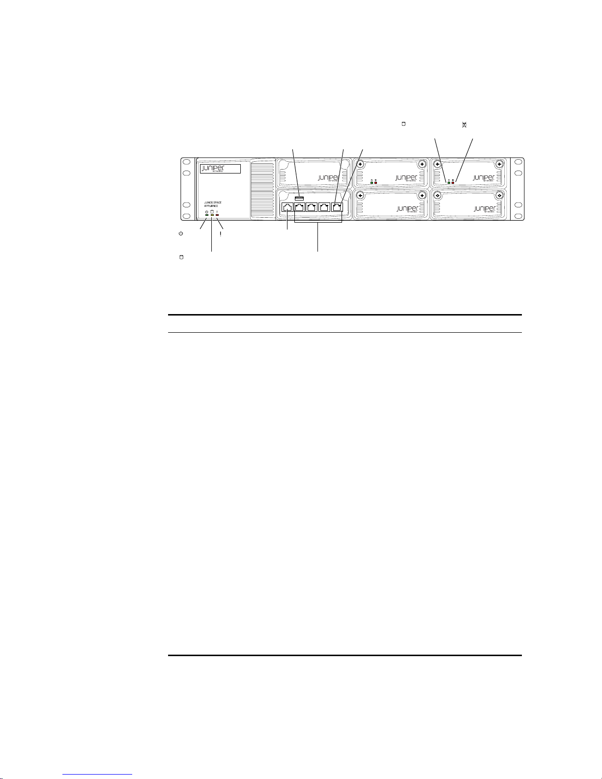
The STRM 500 II appliance has a 2U rack-mountable chassis with optional redundant
AC and DC power supplies, a 2U hot-swappable dual redundant RAID1 array, 8 GB of
memory, and a 4 Gigabit Ethernet controller.
See Figure 1 for the front panel features of the system. Table 2 and Table 3 describes
the front panel features.
STRM Series II Hardware Installation Guide
6 HARDWARE OVERVIEW
CONSOLE ETH3 ETH2 ETH1 ETH0
g040400
Power
LED
Hardware
LED
Hard disk LED Network ports
Console
port
Left
LAN
LED
Right
LAN
LED
STRM 500 II
Hard disk
Activity LED
Hard disk
Failure LED
USB
maintenance
port
Figure 1 STRM 500 II Front Panel
l
Table 2 STRM 500 II Front Panel LEDs
LEDs Description
LED
Chassis LEDs
• Power (green) - Indicates that the
appliance is powered on
• Hard disk (yellow) - Indicates the
hard disk is in use (writing or reading
data)
• Hardware (red) - Indicates that a
fan, power supply, or temperature
alarm has occurred
LAN LEDs
• Left LED (green) - Indicates that the
link is active, Momentary blinks for
activity
• Right LED - Indicates the link speed
- off -10 Mbps
- green - 100 Mbps
- yellow - 1 Gbps
• Hard disk tray LEDs
- Left (green) - For disk activity
- Right (red) - For disk failure
Solid - disk failure
STRM Series II Hardware Installation Guide
Slow blink - mirror re-sync
STRM 500 II Front Panel and Back Panel Indicators and Features 7
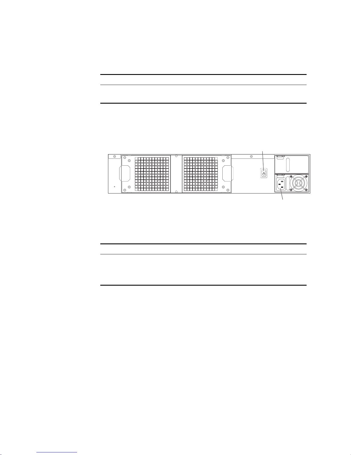
g040042
AC Power supply
receptacle
AC Power
switch
Table 3 STRM 500 II Front Panel Ports
Ports Description
Console port One RJ-45 console port
Network port Four RJ-45 Ethernet 10/100/1000
Back Panel Features See Figure 2 for the back panel features of the system.Table 4 describes the back
panel features.
Figure 2 STRM 500 II Back Panel
Table 4 STRM 500 II Rear View Components
Components Description
Cooling fans Draws air through vents of the chassis
and exhaust it through vents on the
other side of the chassis
Power supply Provides power to all components
STRM Series II Hardware Installation Guide
8 HARDWARE OVERVIEW
STRM 2500 II
!
"#$%
&'
(
"
)*
"
+,
-#
STRM 2500 II Front
Panel and Back
Panel Indicators
and Features
Front Panel
Indicators
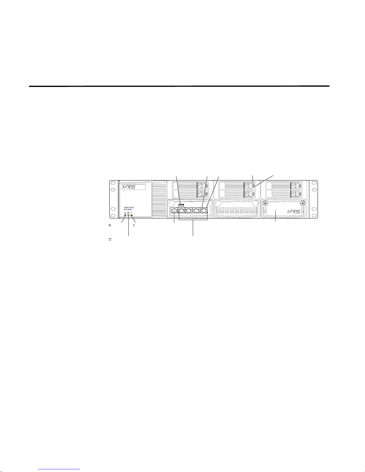
The STRM 2500 II appliance has a 2U rack-mountable chassis with optional redundant
AC and DC power supplies, 2U hot-swappable dual redundant RAID10 array, 8 GB of
memory, and a Gigabit Ethernet controller.
See Figure 3 for the front panel features of the system. Table 5 and Table 6 describes
the front panel features.
Figure 3 STRM 2500 II Front Panel
STRM Series II Hardware Installation Guide
 Loading...