

Page 1

SRX4200 Services Gateway Hardware
Published
2021-01-20
Guide
Page 2

Juniper Networks, Inc.
1133 Innovation Way
Sunnyvale, California 94089
USA
408-745-2000
www.juniper.net
Juniper Networks, the Juniper Networks logo, Juniper, and Junos are registered trademarks of Juniper Networks, Inc. in
the United States and other countries. All other trademarks, service marks, registered marks, or registered service marks
are the property of their respective owners.
Juniper Networks assumes no responsibility for any inaccuracies in this document. Juniper Networks reserves the right
to change, modify, transfer, or otherwise revise this publication without notice.
SRX4200 Services Gateway Hardware Guide
Copyright © 2021 Juniper Networks, Inc. All rights reserved.
The information in this document is current as of the date on the title page.
ii
YEAR 2000 NOTICE
Juniper Networks hardware and software products are Year 2000 compliant. Junos OS has no known time-related
limitations through the year 2038. However, the NTP application is known to have some difficulty in the year 2036.
END USER LICENSE AGREEMENT
The Juniper Networks product that is the subject of this technical documentation consists of (or is intended for use with)
Juniper Networks software. Use of such software is subject to the terms and conditions of the End User License Agreement
(“EULA”) posted at https://support.juniper.net/support/eula/. By downloading, installing or using such software, you
agree to the terms and conditions of that EULA.
Page 3

Table of Contents
1
About the Documentation | ix
Documentation and Release Notes | ix
Using the Examples in This Manual | ix
Merging a Full Example | x
Merging a Snippet | xi
Documentation Conventions | xi
Documentation Feedback | xiv
Requesting Technical Support | xiv
Self-Help Online Tools and Resources | xv
Creating a Service Request with JTAC | xv
iii
Overview
SRX4200 Services Gateway Overview | 17
SRX4200 Services Gateway Overview | 17
Field-Replaceable Units in SRX4200 Services Gateways | 18
Benefits of the SRX4200 Services Gateway | 18
SRX4200 Chassis | 18
SRX4200 Services Gateway Chassis Overview | 19
SRX4200 Services Gateway Front Panel | 19
Chassis Status LEDs | 20
Management Port LEDs | 21
HA Port LEDs | 21
Network Port LEDs | 22
SRX4200 Services Gateway Back Panel | 22
SRX4200 Cooling System | 23
Page 4

SRX4200 Power System | 24
2
SRX4200 Power Supply | 25
AC Power Supply | 25
DC Power Supply | 27
AC Power Supply Specifications for SRX4200 Services Gateways | 28
AC Power Cord Specifications for the SRX4200 Services Gateway | 29
DC Power Supply Specifications for SRX4200 Services Gateways | 30
Site Planning, Preparation, and Specifications
SRX4200 Site Preparation Checklist | 33
SRX4200 Site Guidelines and Requirements | 34
General Site Installation Guidelines | 35
SRX4200 Services Gateway Environmental Specifications | 35
Site Electrical Wiring Guidelines | 36
iv
SRX4200 Services Gateway Physical Specifications | 37
Clearance Requirements for Airflow and Hardware Maintenance for SRX4200 Services
Gateways | 38
SRX4200 Services Gateway Rack Requirements | 39
Cabinet Requirements for SRX4200 Services Gateways | 40
SRX4200 Transceiver Specifications and Pinouts | 41
Pluggable Transceivers Supported on SRX4200 Services Gateways | 41
SFP+ Direct Attach Copper Cables for SRX4200 Services Gateways | 42
Management Port Connector Pinout Information for an SRX4200 Services Gateway | 43
Console Port Connector Pinout Information for an SRX4200 Services Gateway | 43
Page 5

Initial Installation and Configuration
3
4
SRX4200 Installation Overview | 46
Unpacking and Mounting the SRX4200 | 46
Unpacking the SRX4200 Services Gateway | 46
Verifying Parts Received with the SRX4200 Services Gateway | 47
Installing the SRX4200 Services Gateway in a Rack | 48
Connecting the SRX4200 to Power | 50
Connecting the SRX4200 Services Gateway Grounding Cable | 51
Connecting AC Power to an SRX4200 Services Gateway | 52
Connecting DC Power to an SRX4200 Services Gateway | 54
Connecting the SRX4200 Services Gateway to a Management Console | 56
v
Configuring Junos OS on the SRX4200 | 57
SRX4200 Services Gateway Software Configuration Overview | 57
SRX4200 Services Gateway Factory-Default Settings | 57
Viewing Factory-Default Settings | 58
Configuring the SRX4200 Services Gateway | 58
Maintaining Components
Routine Maintenance Procedures for the SRX4200 | 62
Maintaining the SRX4200 Power System | 62
Replacing an AC Power Supply on the SRX4200 | 63
Removing an AC Power Supply from an SRX4200 Services Gateway | 63
Installing an AC Power Supply in an SRX4200 Services Gateway | 64
Replacing a DC Power Supply on the SRX4200 | 65
Removing a DC Power Supply from an SRX4200 Services Gateway | 66
Installing a DC Power Supply in an SRX4200 Services Gateway | 67
Maintaining the SRX4200 Cooling System | 68
Replacing the SRX4200 Services Gateway Fan Tray | 68
Page 6

Troubleshooting Hardware
5
6
7
Troubleshooting the SRX4200 | 71
Troubleshooting Resources for the SRX4200 Services Gateway | 71
Monitoring Chassis Alarms on a SRX4200 Services Gateway | 71
Using the RESET Button on the SRX4200 Services Gateway | 73
Contacting Customer Support and Returning the Chassis or Components
Returning the SRX4200 Chassis or Components | 75
Contacting Customer Support | 75
Returning a SRX4200 Services Gateway or Component to Juniper Networks | 76
Locating the Serial Number on the SRX4200 Services Gateway or Component | 77
Listing the SRX4200 Services Gateway Component Details with the CLI | 77
Locating the Chassis Serial Number ID Label | 78
vi
Locating the Serial Number ID Labels on FRUs | 78
Packing a SRX4200 Services Gateway or Component for Shipping | 78
Packing the SRX4200 Services Gateway for Shipment | 79
Packing the SRX4200 Services Gateway Components for Shipment | 80
Safety and Compliance Information
General Safety Guidelines and Warnings | 83
Definitions of Safety Warning Levels | 84
Restricted Access Warning | 88
Qualified Personnel Warning | 91
Prevention of Electrostatic Discharge Damage | 91
Fire Safety Requirements | 93
Fire Suppression | 93
Fire Suppression Equipment | 93
Laser and LED Safety Guidelines and Warnings | 94
General Laser Safety Guidelines | 95
Class 1 Laser Product Warning | 96
Class 1 LED Product Warning | 97
Laser Beam Warning | 98
Page 7

Radiation from Open Port Apertures Warning | 99
Maintenance and Operational Safety Guidelines and Warnings | 100
Battery Handling Warning | 101
Jewelry Removal Warning | 102
Lightning Activity Warning | 104
Operating Temperature Warning | 105
Product Disposal Warning | 107
General Electrical Safety Guidelines and Warnings | 108
Safety Guidelines and Warnings | 108
Grounded Equipment Warning | 109
Backplane Energy Hazard Warning | 109
Multiple Power Supplies Disconnection Warning | 110
Power Disconnection Warning | 111
vii
TN Power Warning | 112
Copper Conductors Warning | 113
AC Power Electrical Safety Guidelines | 114
DC Power Electrical Safety Guidelines | 114
DC Power Disconnection Warning | 116
DC Power Grounding Requirements and Warning | 118
DC Power Wiring Sequence Warning | 120
DC Power Wiring Terminations Warning | 123
Action to Take After an Electrical Accident | 125
Agency Approvals | 125
Acoustic Noise Compliance Statements | 127
EMC Requirements | 127
Canada | 127
European Community | 128
Israel | 128
Japan | 128
Page 8

United States | 128
Statements of Volatility for Juniper Network Devices | 129
viii
Page 9
About the Documentation
IN THIS SECTION
Documentation and Release Notes | ix
Using the Examples in This Manual | ix
Documentation Conventions | xi
Documentation Feedback | xiv
Requesting Technical Support | xiv
Use this guide to install hardware and perform initial software configuration, routine maintenance, and
troubleshooting for the SRX4200 Services Gateway. After completing the installation and basic configuration
procedures covered in this guide, refer to the Junos OS documentation for information about further
software configuration.
ix
Documentation and Release Notes
To obtain the most current version of all Juniper Networks®technical documentation, see the product
documentation page on the Juniper Networks website at https://www.juniper.net/documentation/.
If the information in the latest release notes differs from the information in the documentation, follow the
product Release Notes.
Juniper Networks Books publishes books by Juniper Networks engineers and subject matter experts.
These books go beyond the technical documentation to explore the nuances of network architecture,
deployment, and administration. The current list can be viewed at https://www.juniper.net/books.
Using the Examples in This Manual
If you want to use the examples in this manual, you can use the load merge or the load merge relative
command. These commands cause the software to merge the incoming configuration into the current
candidate configuration. The example does not become active until you commit the candidate configuration.
Page 10

If the example configuration contains the top level of the hierarchy (or multiple hierarchies), the example
is a full example. In this case, use the load merge command.
If the example configuration does not start at the top level of the hierarchy, the example is a snippet. In
this case, use the load merge relative command. These procedures are described in the following sections.
Merging a Full Example
To merge a full example, follow these steps:
1. From the HTML or PDF version of the manual, copy a configuration example into a text file, save the
file with a name, and copy the file to a directory on your routing platform.
For example, copy the following configuration to a file and name the file ex-script.conf. Copy the
ex-script.conf file to the /var/tmp directory on your routing platform.
system {
scripts {
commit {
file ex-script.xsl;
}
}
}
interfaces {
fxp0 {
disable;
unit 0 {
family inet {
address 10.0.0.1/24;
}
}
}
}
x
2. Merge the contents of the file into your routing platform configuration by issuing the load merge
configuration mode command:
[edit]
user@host# load merge /var/tmp/ex-script.conf
load complete
Page 11

Merging a Snippet
To merge a snippet, follow these steps:
1. From the HTML or PDF version of the manual, copy a configuration snippet into a text file, save the
file with a name, and copy the file to a directory on your routing platform.
For example, copy the following snippet to a file and name the file ex-script-snippet.conf. Copy the
ex-script-snippet.conf file to the /var/tmp directory on your routing platform.
commit {
file ex-script-snippet.xsl; }
2. Move to the hierarchy level that is relevant for this snippet by issuing the following configuration mode
command:
[edit]
user@host# edit system scripts
[edit system scripts]
xi
3. Merge the contents of the file into your routing platform configuration by issuing the load merge
relative configuration mode command:
[edit system scripts]
user@host# load merge relative /var/tmp/ex-script-snippet.conf
load complete
For more information about the load command, see CLI Explorer.
Documentation Conventions
Table 1 on page xii defines notice icons used in this guide.
Page 12
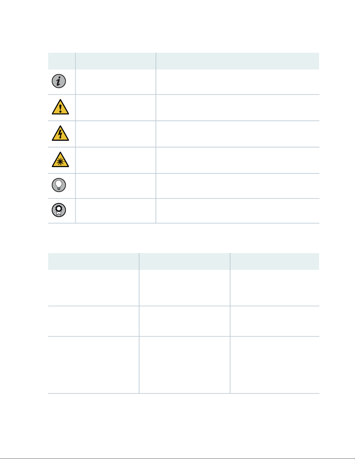
Table 1: Notice Icons
xii
DescriptionMeaningIcon
Indicates important features or instructions.Informational note
Caution
Indicates a situation that might result in loss of data or hardware
damage.
Alerts you to the risk of personal injury or death.Warning
Alerts you to the risk of personal injury from a laser.Laser warning
Indicates helpful information.Tip
Alerts you to a recommended use or implementation.Best practice
Table 2 on page xii defines the text and syntax conventions used in this guide.
Table 2: Text and Syntax Conventions
ExamplesDescriptionConvention
Fixed-width text like this
Italic text like this
Represents text that you type.Bold text like this
Represents output that appears on
the terminal screen.
Introduces or emphasizes important
•
new terms.
Identifies guide names.
•
Identifies RFC and Internet draft
•
titles.
To enter configuration mode, type
the configure command:
user@host> configure
user@host> show chassis alarms
No alarms currently active
A policy term is a named structure
•
that defines match conditions and
actions.
Junos OS CLI User Guide
•
RFC 1997, BGP Communities
•
Attribute
Page 13

Table 2: Text and Syntax Conventions (continued)
xiii
ExamplesDescriptionConvention
Italic text like this
Text like this
< > (angle brackets)
| (pipe symbol)
Represents variables (options for
which you substitute a value) in
commands or configuration
statements.
Represents names of configuration
statements, commands, files, and
directories; configuration hierarchy
levels; or labels on routing platform
components.
variables.
Indicates a choice between the
mutually exclusive keywords or
variables on either side of the symbol.
The set of choices is often enclosed
in parentheses for clarity.
Configure the machine’s domain
name:
[edit]
root@# set system domain-name
domain-name
To configure a stub area, include
•
the stub statement at the [edit
protocols ospf area area-id]
hierarchy level.
The console port is labeled
•
CONSOLE.
stub <default-metric metric>;Encloses optional keywords or
broadcast | multicast
(string1 | string2 | string3)
# (pound sign)
[ ] (square brackets)
Indention and braces ( { } )
; (semicolon)
GUI Conventions
Indicates a comment specified on the
same line as the configuration
statement to which it applies.
Encloses a variable for which you can
substitute one or more values.
Identifies a level in the configuration
hierarchy.
Identifies a leaf statement at a
configuration hierarchy level.
rsvp { # Required for dynamic MPLS
only
community name members [
community-ids ]
[edit]
routing-options {
static {
route default {
nexthop address;
retain;
}
}
}
Page 14
Table 2: Text and Syntax Conventions (continued)
xiv
ExamplesDescriptionConvention
Bold text like this
> (bold right angle bracket)
Represents graphical user interface
(GUI) items you click or select.
Separates levels in a hierarchy of
menu selections.
In the Logical Interfaces box, select
•
All Interfaces.
To cancel the configuration, click
•
Cancel.
In the configuration editor hierarchy,
select Protocols>Ospf.
Documentation Feedback
We encourage you to provide feedback so that we can improve our documentation. You can use either
of the following methods:
Online feedback system—Click TechLibrary Feedback, on the lower right of any page on the Juniper
•
Networks TechLibrary site, and do one of the following:
Click the thumbs-up icon if the information on the page was helpful to you.
•
Click the thumbs-down icon if the information on the page was not helpful to you or if you have
•
suggestions for improvement, and use the pop-up form to provide feedback.
E-mail—Send your comments to [email protected]. Include the document or topic name,
•
URL or page number, and software version (if applicable).
Requesting Technical Support
Technical product support is available through the Juniper Networks Technical Assistance Center (JTAC).
If you are a customer with an active Juniper Care or Partner Support Services support contract, or are
Page 15

covered under warranty, and need post-sales technical support, you can access our tools and resources
online or open a case with JTAC.
JTAC policies—For a complete understanding of our JTAC procedures and policies, review the JTAC User
•
Guide located at https://www.juniper.net/us/en/local/pdf/resource-guides/7100059-en.pdf.
Product warranties—For product warranty information, visit https://www.juniper.net/support/warranty/.
•
JTAC hours of operation—The JTAC centers have resources available 24 hours a day, 7 days a week,
•
365 days a year.
Self-Help Online Tools and Resources
For quick and easy problem resolution, Juniper Networks has designed an online self-service portal called
the Customer Support Center (CSC) that provides you with the following features:
Find CSC offerings: https://www.juniper.net/customers/support/
•
Search for known bugs: https://prsearch.juniper.net/
•
xv
Find product documentation: https://www.juniper.net/documentation/
•
Find solutions and answer questions using our Knowledge Base: https://kb.juniper.net/
•
Download the latest versions of software and review release notes:
•
https://www.juniper.net/customers/csc/software/
Search technical bulletins for relevant hardware and software notifications:
•
https://kb.juniper.net/InfoCenter/
Join and participate in the Juniper Networks Community Forum:
•
https://www.juniper.net/company/communities/
Create a service request online: https://myjuniper.juniper.net
•
To verify service entitlement by product serial number, use our Serial Number Entitlement (SNE) Tool:
https://entitlementsearch.juniper.net/entitlementsearch/
Creating a Service Request with JTAC
You can create a service request with JTAC on the Web or by telephone.
Visit https://myjuniper.juniper.net.
•
Call 1-888-314-JTAC (1-888-314-5822 toll-free in the USA, Canada, and Mexico).
•
For international or direct-dial options in countries without toll-free numbers, see
https://support.juniper.net/support/requesting-support/.
Page 16

1
CHAPTER
Overview
SRX4200 Services Gateway Overview | 17
SRX4200 Chassis | 18
SRX4200 Cooling System | 23
SRX4200 Power System | 24
Page 17
SRX4200 Services Gateway Overview
IN THIS SECTION
SRX4200 Services Gateway Overview | 17
Field-Replaceable Units in SRX4200 Services Gateways | 18
Benefits of the SRX4200 Services Gateway | 18
SRX4200 Services Gateway Overview
The Juniper Networks SRX4200 Services Gateway is a high-performance, scalable mid-range services
gateway, which consolidates security, next-generation firewall, and advanced threat prevention capabilities
to provide secure connectivity. The services gateway supports 40 Gbps IMIX throughput and is suited for
small to medium enterprises and data centers.
17
The SRX4200 Services Gateway supports advanced threat prevention through Sky Advanced Threat
Prevention (Sky ATP) and Spotlight Secure Threat Intelligence, in addition to key features such as VPN,
IPS, and UTM.
The chassis is 1 U high and is designed for rack installation. The services gateway is shipped with dual
power supplies and is available in both AC-powered and DC-powered versions:
SRX4200 (AC) — SRX4200 Services Gateway with dual AC power supplies
•
SRX4200 (DC) — SRX4200 Services Gateway with dual DC power supplies
•
The SRX4200 Services Gateway comes with 64 GB of DDR4 memory and two 240-GB solid-state drives
(SSDs) in a redundant array of independent disks (RAID). Both disks are configured as a RAID-1 mirror
(data is concurrently written to both SSDs). If one SSD becomes inoperable, the other SSD continues to
be active.
The services gateway runs the Junos OS and can be managed using the CLI, Junos Space, and J-Web.
SEE ALSO
SRX4200 Services Gateway Physical Specifications | 37
SRX4200 Services Gateway Environmental Specifications | 35
Page 18
Field-Replaceable Units in SRX4200 Services Gateways
Field-replaceable units (FRUs) are components that you can replace at your site. The FRUs on the SRX4200
Services Gateway are hot-removable and hot-insertable. You can remove and replace them without
powering off the services gateway. The services gateway supports the following FRUs:
AC power supplies
•
DC power supplies
•
Fan trays
•
SEE ALSO
SRX4200 Power Supply | 25
18
Benefits of the SRX4200 Services Gateway
High performance—The SRX4200 supports up to 80-Gbps firewall throughput (up to 40-Gbps of IMIX
•
firewall throughput) and is suited for enterprise campus and data center edge deployments.
Advanced threat protection—The SRX4000 line of services gateways supports the intrusion prevention
•
system (IPS), Juniper Sky Advanced Threat Prevention (Juniper Sky ATP), antivirus, and antispam features,
which protect against potential vulnerabilities. Juniper Sky ATP protects against zero-day attacks and
other unknown threats.
SRX4200 Chassis
IN THIS SECTION
SRX4200 Services Gateway Chassis Overview | 19
SRX4200 Services Gateway Front Panel | 19
SRX4200 Services Gateway Back Panel | 22
Page 19
SRX4200 Services Gateway Chassis Overview
The 4200 Services Gateway chassis is a rigid sheet metal structure that houses all the other hardware
components. The chassis measures 1.75 in. high, 17.48 in. wide, and 25 in. deep. The chassis installs in
standard 600-mm deep (or larger) enclosed cabinets or 19-in. equipment racks.
CAUTION: Before removing or installing components of a functioning services
gateway, attach an electrostatic discharge (ESD) strap to an ESD point and place the
other end of the strap around your bare wrist. Failure to use an ESD strap could result
in damage to the device.
The services gateway must be connected to earth ground during normal operation.
19
SRX4200 Services Gateway Front Panel
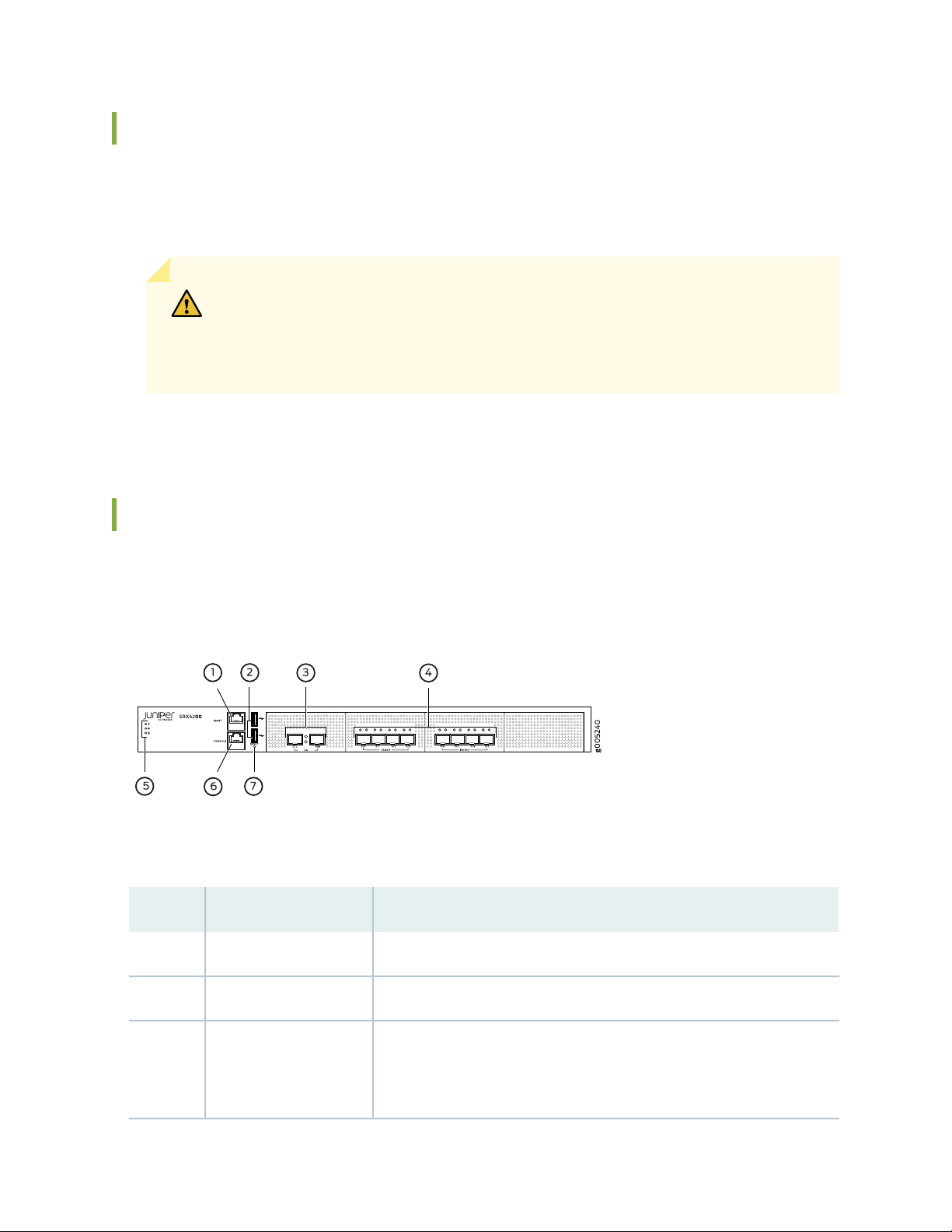
Figure 1 on page 19 shows the front panel of the SRX4200 Services Gateway.
Figure 1: SRX4200 Services Gateway Front Panel
Table 3 on page 19 lists the components on the front panel of the services gateway.
Table 3: SRX4200 Services Gateway Components on the Front Panel
DescriptionComponentNumber
Gigabit Ethernet port to connect to the device over the network.Management port1
Two USB 2.0 ports that accept a USB storage device.USB ports2
HA ports3
Two 10-Gigabit Ethernet ports, CTL (control port) and FAB (fabric port), to
synchronize data and maintain state information in a chassis cluster setup.
These ports support enhanced small form-factor pluggable (SFP+)
transceivers.
Page 20
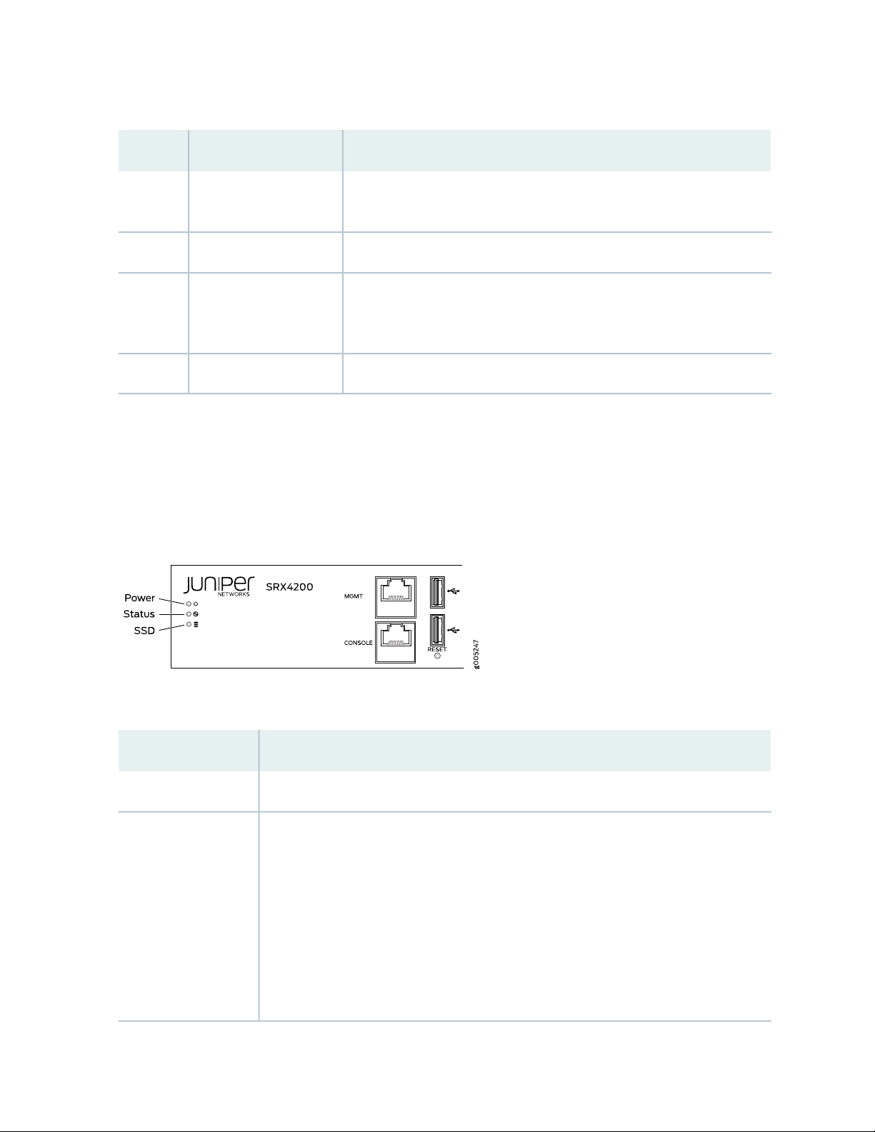
Table 3: SRX4200 Services Gateway Components on the Front Panel (continued)
DescriptionComponentNumber
20
SFP+ ports4
Console port6
Eight 1-Gigabit Ethernet/10-Gigabit Ethernet SFP+ ports for network
traffic.
Indicate component and system status at a glance.LEDs5
Connects a laptop to the services gateway for CLI management. The port
uses an RJ-45 serial connection, is configured as DTE, and supports the
RS-232 (EIA-232) standard.
Returns the services gateway to the factory-default configuration.Reset button7
Chassis Status LEDs
Figure 2 on page 20 shows the front panel LEDs and Table 4 on page 20 describes the LEDs.
Figure 2: SRX4200 Services Gateway Front Panel LEDs
Table 4: SRX4200 Services Gateway Front Panel LEDs
DescriptionLED
Solid green—receiving powerPower
•
Status
Solid green—operating normally
•
Solid red—critical alarm
•
Hardware component failure
•
Software module failure
•
Fan failure (atleast one)
•
Blinking red—noncritical alarm
•
The other HA node is in the lost, disabled, or ineligible state.
•
Off—the system is not receiving power
•
Page 21
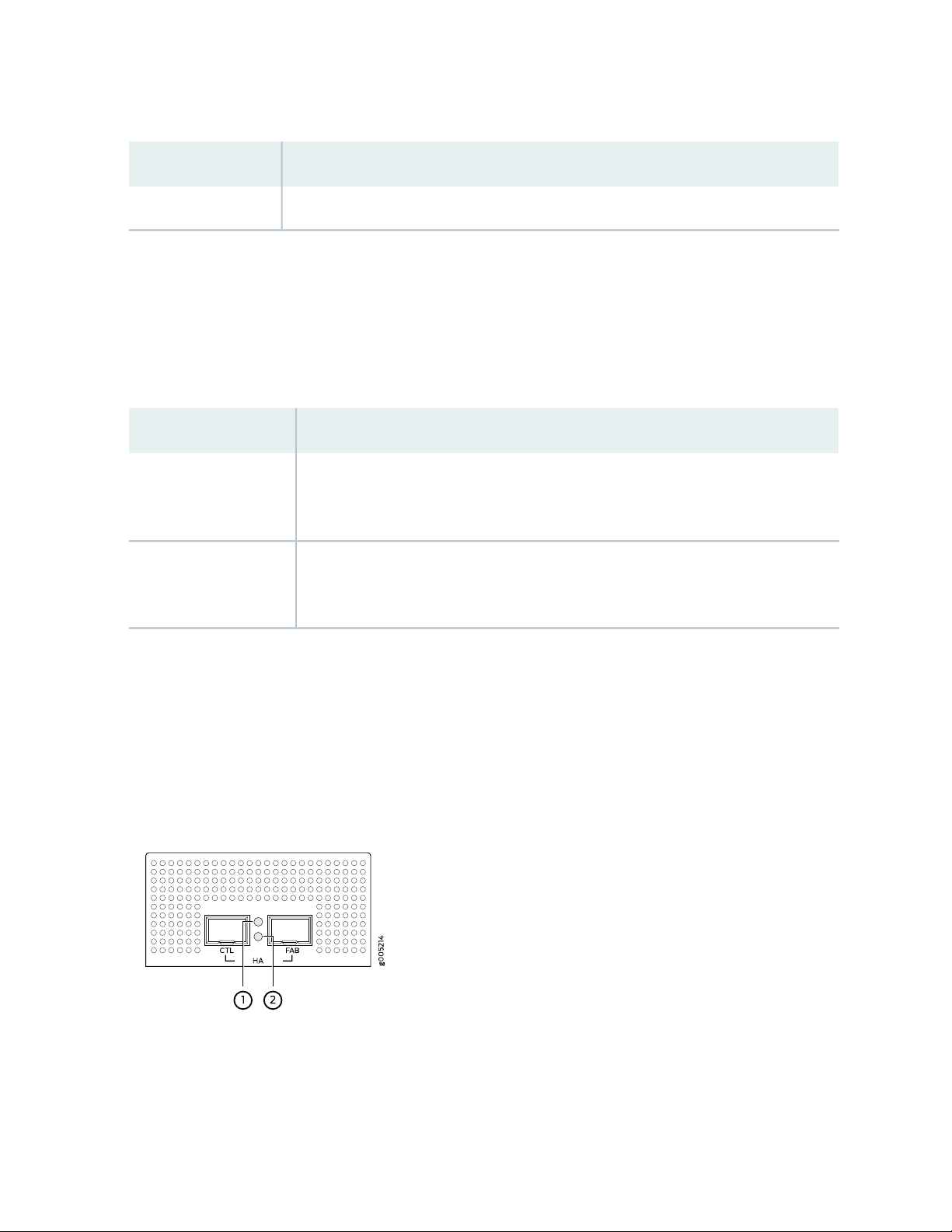
Table 4: SRX4200 Services Gateway Front Panel LEDs (continued)
DescriptionLED
Blinking green—indicates hard disk drive (SSD) activitySSD
•
Management Port LEDs
The management port has two LEDs that indicate link activity and status of the management port.
Table 5 on page 21 describes the LEDs.
Table 5: Management Port LEDs
DescriptionLED
21
Link/Activity (LED on the
left)
Speed (LED on the right)
Solid amber—A link is established, but there is no activity on the link.
•
Blinking amber—There is link activity.
•
Off—There is no link established.
•
Solid green—100-Mbps link is established.
•
Solid amber—1000-Mbps link is established.
•
Off—There is no link established.
•
HA Port LEDs
Each HA port has one status LED located between the ports. Figure 3 on page 21 shows the LEDs. The
upper LED (callout 1) displays the status for the port on the right and the lower LED (callout 2) displays
the status for the port on the left. Table 6 on page 22 describes the LEDs.
Figure 3: HA Port LEDs
Page 22
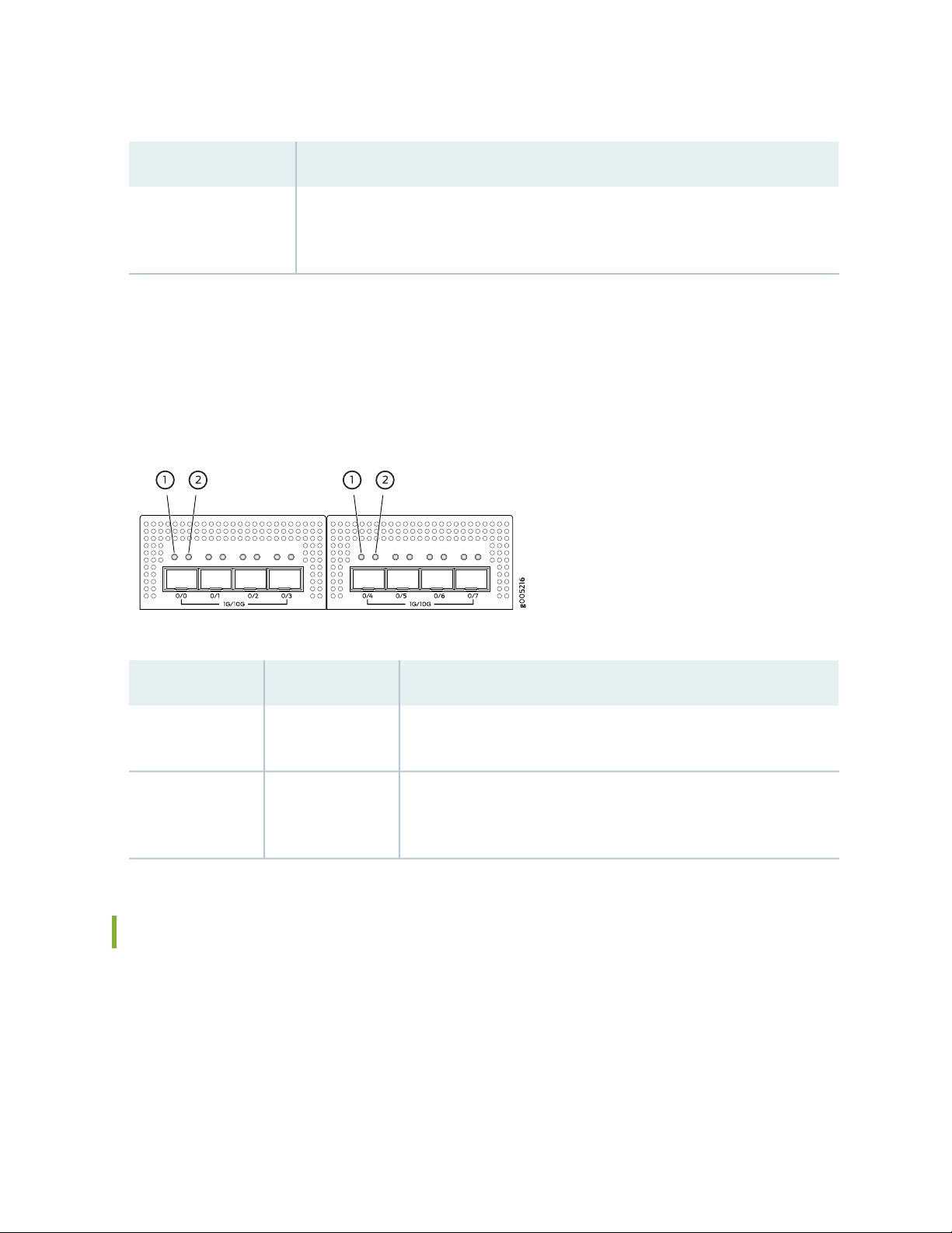
Table 6: HA Port LEDs
22
DescriptionLED
Status LED
Solid amber—A link is established.
•
Blinking amber—There is link activity.
•
Off—There is no link established.
•
Network Port LEDs
Each SFP+ port has two status LEDs located above the port. Table 7 on page 22 describes the LEDs.
Figure 4 on page 22 shows the LEDs.
Figure 4: Network Port LEDs
Table 7: Network Port LEDs
DescriptionLEDCallout
1
2
Link (LED on the
left)
Speed/Activity
(LED on the right)
Solid green—There is link activity.
•
Off—There is no link established.
•
Solid amber—10G/1G link is established.
•
Blinking amber—There is activity on the 10G/1G link.
•
Off—There is no link established.
•
SRX4200 Services Gateway Back Panel
Figure 5 on page 23 shows the back panel of the SRX4200 Services Gateway, and Table 8 on page 23 lists
and describes the back panel components.
Page 23
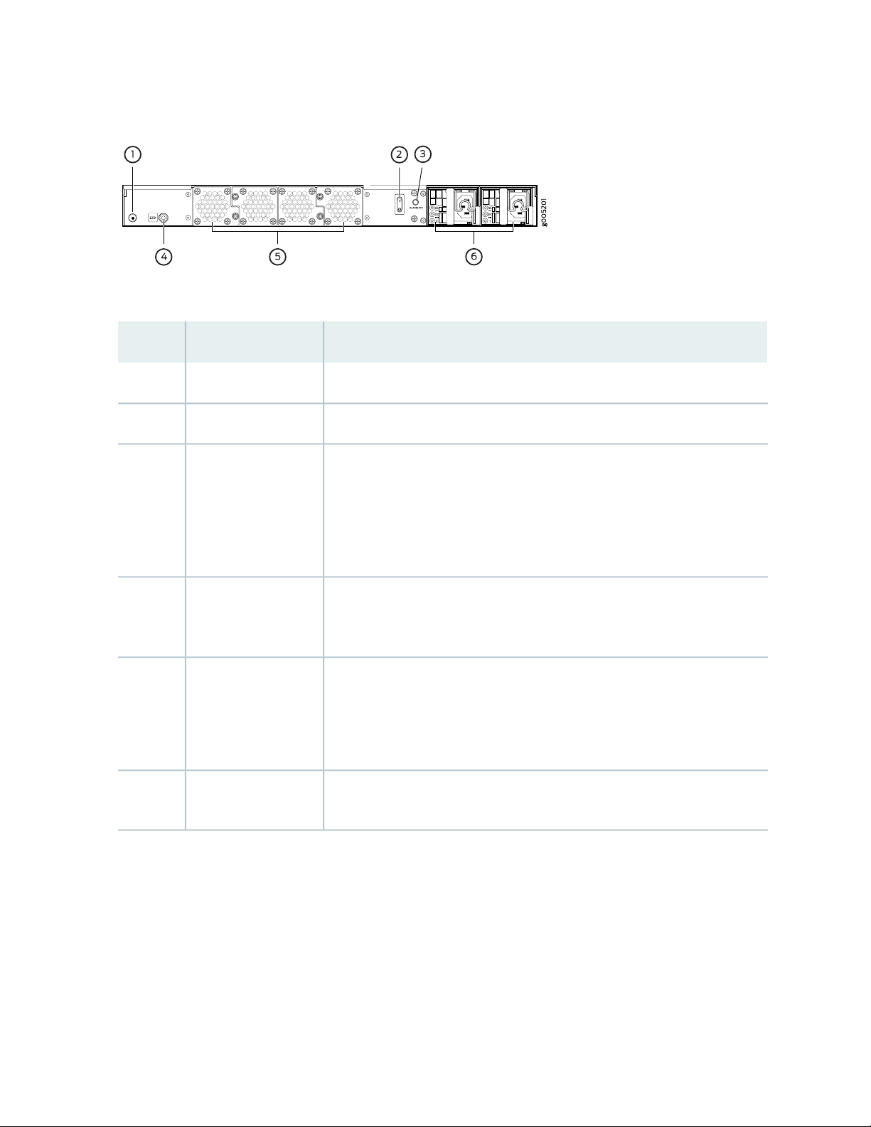
Figure 5: SRX4200 Services Gateway Back Panel
Table 8: SRX4200 Services Gateway Back Panel Components
DescriptionComponentNumber
Connects the services gateway chassis to earth ground.Grounding point1
Use the Power switch to power on or power off the services gateway.Power switch2
23
Alarm Off button3
ESD point4
Fan trays5
Power supply6
Use this button to turn off an alarm triggered because of an abnormal DC
output voltage caused by any of the following:
Only one power supply unit is plugged in.
•
The AC power cord is not plugged in.
•
The power supply unit is not functional and there is no DC output.
•
For personal safety, while working on the services gateway, use the ESD outlet
to plug in an ESD grounding strap to prevent your body from sending static
charges to the services gateway.
Four fan trays for cooling the services gateway and its components. Each fan
tray contains two fans.
Three fan trays are required for proper air flow across the chassis internal
components. The fourth fan tray provides redundancy.
Two power supply slots. Each power supply contains a power cord outlet. Two
650-W DC or AC power supplies are provided with the services gateway.
SRX4200 Cooling System
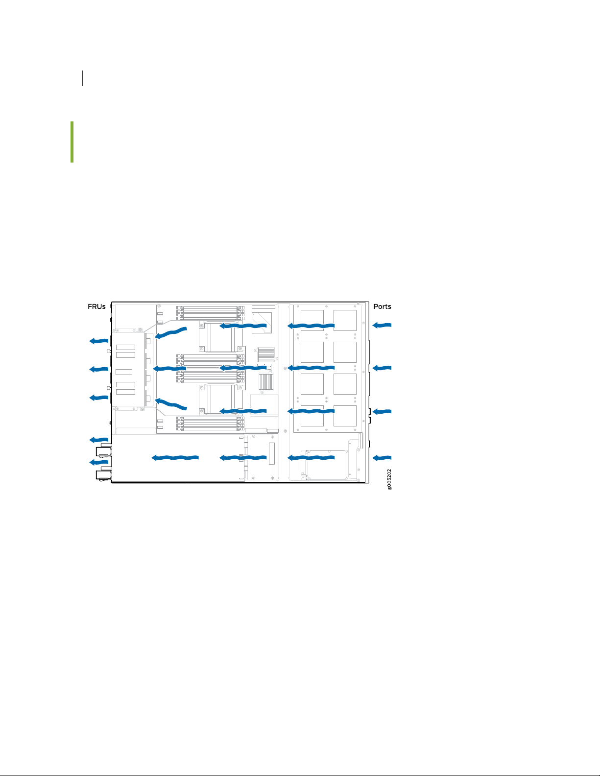
The cooling system for the services gateway consists of four fan trays located at the rear of the chassis.
Each fan tray contains two fans, so there are a total of eight fans. The fans draw cool air through vents on
Page 24
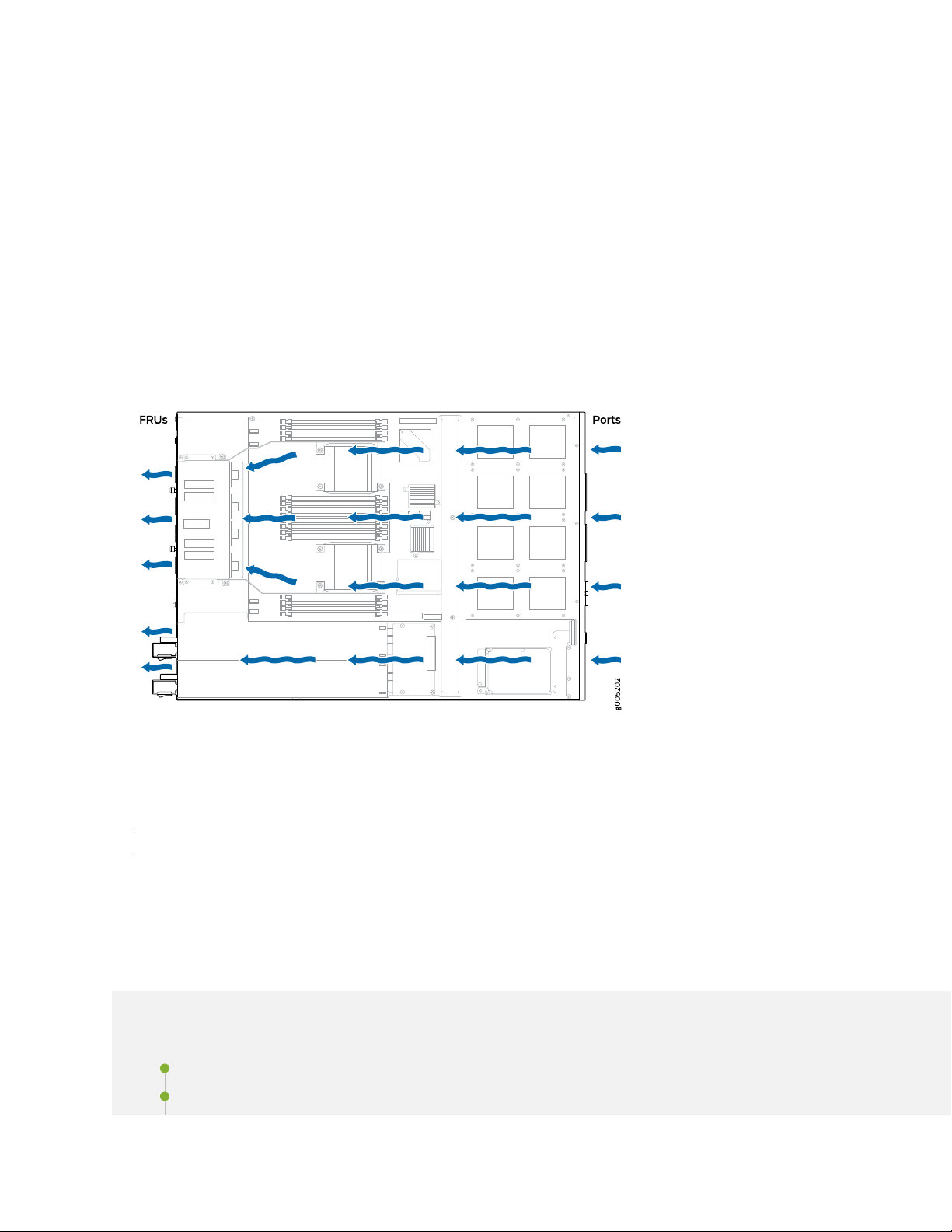
the front of the chassis and exhaust the air through the back of the chassis. See Figure 6 on page 24. The
airflow produced by the fans keeps device components within the acceptable temperature range.
If any one of the four fan trays fails, the services gateway generates a warning but keeps the system
running. If the temperature keeps rising, the services gateway lowers the power consumption by reducing
the performance or shutting down some of the chassis components. However, if the ambient maximum
temperature exceeds the warning level and the system cannot be adequately cooled, then the services
gateway shuts down the system and hardware components completely.
The fan trays are hot-swappable field-replaceable units (FRUs). The fans are not field-replaceable.
Figure 6: Airflow Through the Chassis
24
RELATED DOCUMENTATION
Clearance Requirements for Airflow and Hardware Maintenance for SRX4200 Services Gateways | 38
SRX4200 Power System
IN THIS SECTION
SRX4200 Power Supply | 25
AC Power Supply Specifications for SRX4200 Services Gateways | 28
Page 25
AC Power Cord Specifications for the SRX4200 Services Gateway | 29
DC Power Supply Specifications for SRX4200 Services Gateways | 30
SRX4200 Power Supply
IN THIS SECTION
AC Power Supply | 25
DC Power Supply | 27
25
The SRX4200 Services Gateway is shipped with two AC or two DC power supply units preinstalled in the
rear panel. Each power supply provides power to all components in the services gateway. If one power
supply fails or is removed, the remaining power supply redistributes the electrical load without interruption.
Each power supply is cooled by its own internal cooling system.
AC Power Supply
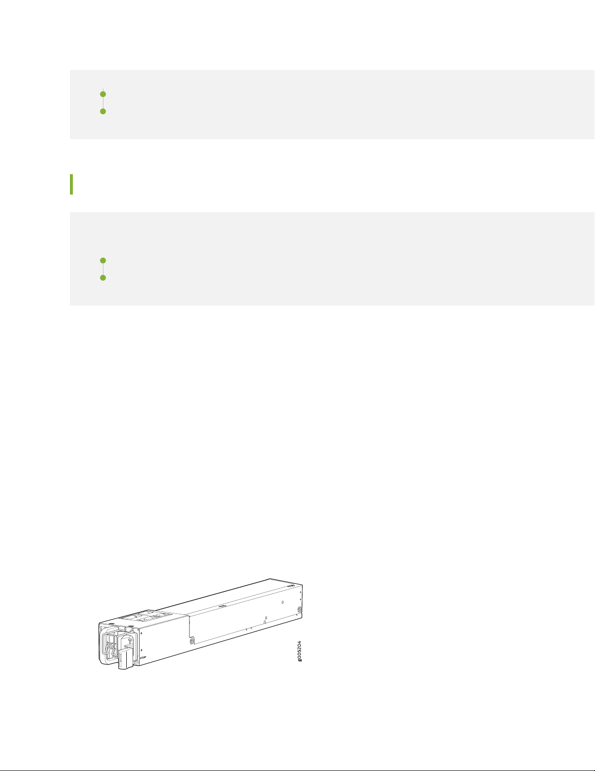
Each AC power supply weighs approximately 2.3 lb and consists of one AC appliance inlet, a fan, and LEDs
for monitoring the status of the power supply. The AC power supply is a hot-insertable and hot-removable
field-replaceable unit (FRU) when the second power supply is installed and running. You can install the
replacement power supply without powering off the services gateway. The AC power supply gives an
output of 650 W and supports both low line voltage (100–127 VAC) and high line voltage (200–240 VAC).
Figure 7 on page 25 shows the AC power supply.
Figure 7: AC Power Supply
Page 26
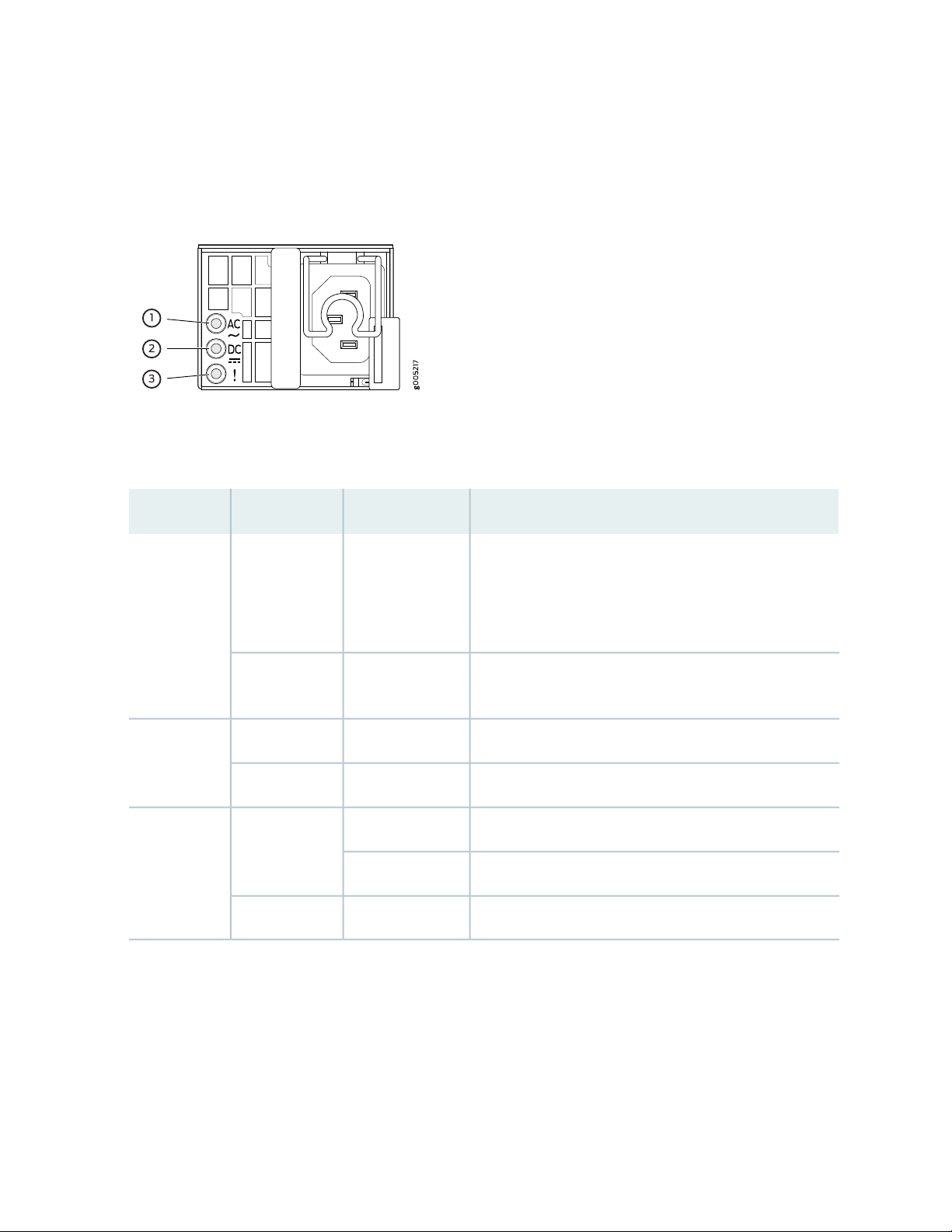
Figure 8 on page 26 shows the location of the LEDs on an AC power supply. Each AC power supply
faceplate contains three LEDs that indicate the status of the power supplies.
Figure 8: AC Power Supply LEDs
Table 9 on page 26 describes the AC power supply LEDs.
Table 9: AC Power Supply LEDs
DescriptionStateColorLED
26
OffUnlitAC
SteadyGreen
Indicates one of the following:
Power input voltage is not within the normal operating
•
range.
No power input.
•
Input power present and is within the normal operating
range.
No DC power output or abnormal DC output.OffUnlitDC
DC power output is within the normal operating range.On steadilyGreen
Power supply unit failure.On steadilyAmber! (Fault)
Invalid power supply unit.Blinking
Power supply unit is functioning normally.OffUnlit
Page 27
NOTE:
If both the AC LED and the DC LED are unlit, either the AC power cord is not installed properly
•
or the power supply fuse has failed.
If the AC LED is lit and the DC LED is unlit, the AC power supply is installed properly, but the
•
power supply has an internal failure.
DC Power Supply
Each DC power supply weighs approximately 2.2 lb and has two independent pairs of DC input lugs, a fan,
and LEDs for monitoring the status of the power supply. The DC power supply in the services gateway is
a hot-insertable and hot-removable field-replaceable unit (FRU) when the second power supply is installed
and running. You can install a replacement power supply without powering off the services gateway. The
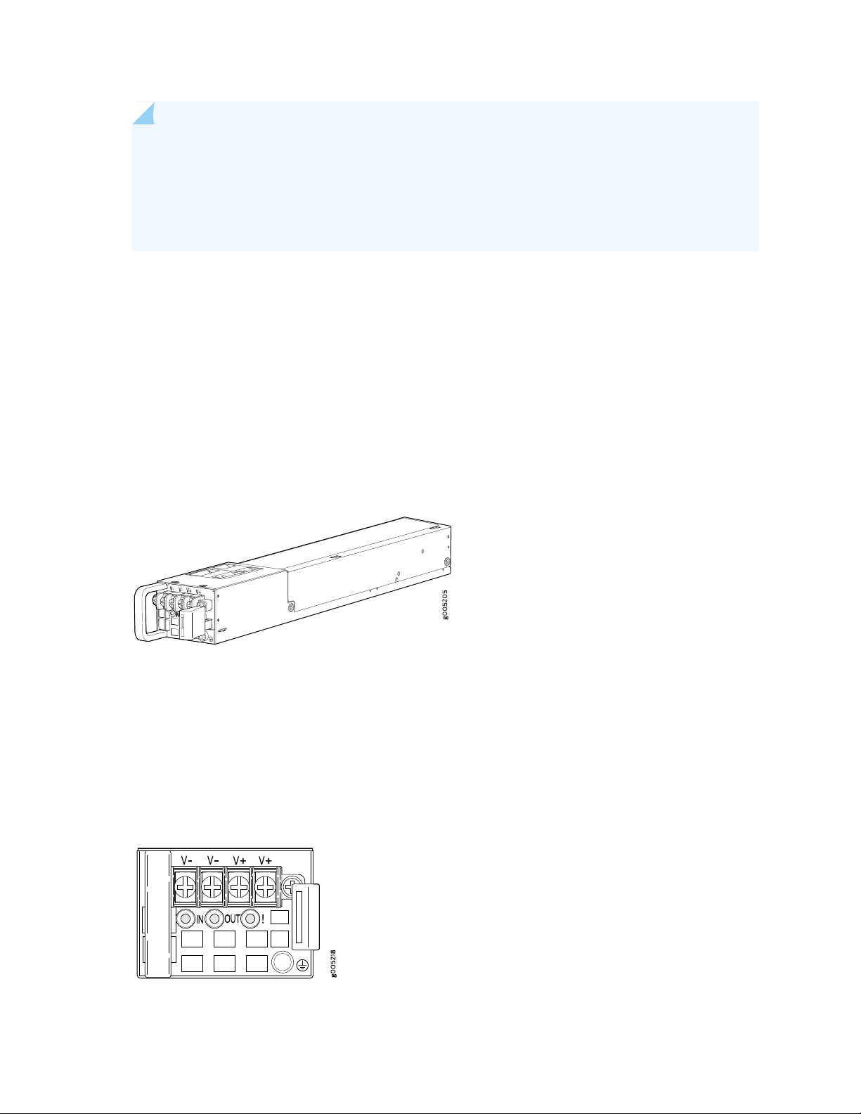
DC power supply gives an output of 650 W. Figure 9 on page 27 shows the DC power supply.
27
Figure 9: DC Power Supply
The DC power supply requires a dedicated circuit breaker rated for 9 A (–48 VDC) minimum, or as required
by local code.
Figure 10 on page 27 shows the location of the LEDs on a DC power supply. Each DC power supply
faceplate contains three LEDs that indicate the status of the power supplies.
Figure 10: DC Power Supply LEDs
Page 28

Table 10 on page 28 describes the DC power supply LEDs.
Table 10: DC Power Supply LEDs
DescriptionStateColorLED
28
OffUnlitIN
On steadilyGreen
Indicates one of the following:
Power input voltage is not within the normal operating
•
range.
No power input.
•
Input power present and is within the normal operating
range.
No DC power output or abnormal DC output.OffUnlitOUT
DC power output is within the normal operating range.On steadilyGreen
Power supply unit failure.On steadilyAmber! (Fault)
Invalid power supply unit.Blinking
Power supply unit is functioning normally.OffUnlit
AC Power Supply Specifications for SRX4200 Services Gateways
Table 11 on page 28 lists the specifications for an AC power supply.
Table 11: AC Power Supply Specifications
SpecificationItem
AC input voltage
AC input current rating
AC output power
Operating range:
Low-voltage line—100–127 VAC
•
High-voltage line—200–240 VAC
•
50–60 HzAC input line frequency
Low-voltage line—4 A
•
High-voltage line—2 A
•
Low-voltage line—650 W
•
High-voltage line—650 W
•
Page 29

Table 11: AC Power Supply Specifications (continued)
SpecificationItem
440 WMaximum System Power Requirement
1500 BTU/HourSystem Thermal Output = (Maximum System Power
Requirement ) * 3.41
Note: 1 W = 3.41 BTU/Hour
AC Power Cord Specifications for the SRX4200 Services Gateway
A detachable AC power cord is supplied with the AC power supplies. The coupler is type C13 as described
by International Electrotechnical Commission (IEC) standard 60320.
29
NOTE: In North America, AC power cords must not exceed 4.5 m (approximately 14.75 ft) in
length, to comply with National Electrical code (NEC) Section 400-8 (NFPA 75, 5-2.2) and 210-52,
and Canadian Electrical Code (CEC) Section 4-010(3).
Table 12 on page 29 provides power cord specifications, and Figure 11 on page 30 depicts the plug on
the AC power cord provided for each country or region.
Table 12: AC Power Cord Specifications
Plug StandardsElectrical SpecificationCountry
AS/NZ 3112-1993250 VAC, 10 A, 50 HzAustralia
250 VAC, 10 A, 50 HzChina
GB2099.1 1996 and
GB 1002 1996
(CH1-10P)
CEE (7) VII250 VAC, 10 A, 50 HzEurope (except Italy and United Kingdom)
CEI 23-16/VII250 VAC, 10 A, 50 HzItaly
Japan
JIS 8303125 VAC, 12 A, 50 or 60
Hz
NEMA 5-15125 VAC, 10 A, 60 HzNorth America
Page 30
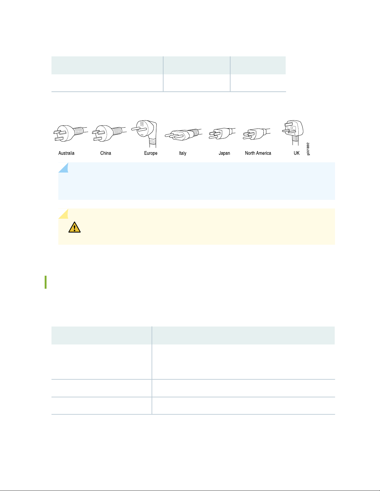
Table 12: AC Power Cord Specifications (continued)
Plug StandardsElectrical SpecificationCountry
BS 1363A250 VAC, 10 A, 50 HzUnited Kingdom
Figure 11: AC Plug Types
NOTE: Power cords and cables must not block access to services gateway components or drape
where people might trip on them.
30
CAUTION: The AC power cord for the services gateway is intended for use with the
services gateway only and not for any other use.
DC Power Supply Specifications for SRX4200 Services Gateways
Table 13 on page 30 lists the power supply specifications for a DC power supply.
Table 13: DC Power Supply Specifications
SpecificationsItem
DC input voltage
Minimum operating voltage: –40 VDC
•
Nominal operating voltage: –48 VDC
•
Operating voltage range: –40 VDC through –72 VDC
•
9 A maximum at nominal operating voltageDC input current rating
650 WOutput power
Page 31

RELATED DOCUMENTATION
Connecting the SRX4200 to Power | 50
Maintaining the SRX4200 Power System | 62
31
Page 32

2
CHAPTER
Site Planning, Preparation, and
Specifications
SRX4200 Site Preparation Checklist | 33
SRX4200 Site Guidelines and Requirements | 34
SRX4200 Transceiver Specifications and Pinouts | 41
Page 33

SRX4200 Site Preparation Checklist
Table 14 on page 33 provides a checklist of tasks you need to perform when preparing a site for installing
the SRX4200 Services Gateway.
Table 14: Site Preparation Checklist for SRX4200 Services Gateway Installation
Performed
ByAdditional InformationItem or Task
Power
Measure distance between external power
sources and device installation site.
Locate sites for connection of system
grounding.
NotesDate
33
Calculate the power consumption and
requirements.
Environment
Verify that environmental factors such as
temperature and humidity do not exceed device
tolerances.
Rack or Cabinet
Verify that your rack or cabinet meets the
minimum requirements for the installation of
the device.
“AC Power Supply
Specifications for SRX4200
Services Gateways” on page 28
“DC Power Supply
Specifications for SRX4200
Services Gateways” on page 30
“SRX4200 Services Gateway
Environmental Specifications”
on page 35
“SRX4200 Services Gateway
Rack Requirements” on page 39
“Cabinet Requirements for
SRX4200 Services Gateways”
on page 40
Plan rack location, including required space
clearances.
Page 34
Table 14: Site Preparation Checklist for SRX4200 Services Gateway Installation (continued)
Performed
ByAdditional InformationItem or Task
Secure the rack or cabinet to the floor and
building structure.
Cables
Acquire cables and connectors:
Determine the number of cables needed
•
based on your planned configuration.
Review the maximum distance allowed for
•
each cable. Choose the length of cable based
on the distance between the hardware
components being connected.
34
NotesDate
Plan the cable routing and management.
RELATED DOCUMENTATION
SRX4200 Installation Overview | 46
SRX4200 Site Guidelines and Requirements
IN THIS SECTION
General Site Installation Guidelines | 35
SRX4200 Services Gateway Environmental Specifications | 35
Site Electrical Wiring Guidelines | 36
SRX4200 Services Gateway Physical Specifications | 37
Clearance Requirements for Airflow and Hardware Maintenance for SRX4200 Services Gateways | 38
SRX4200 Services Gateway Rack Requirements | 39
Cabinet Requirements for SRX4200 Services Gateways | 40
Page 35

General Site Installation Guidelines
To plan and create an acceptable operating environment for your services gateway and prevent
environmentally caused equipment failures:
Follow the prescribed electrostatic discharge (ESD) prevention procedures to prevent damaging the
•
equipment. Static discharge can cause components to fail completely or intermittently over time.
Follow prescribed airflow guidelines to ensure that the cooling system functions properly. The airflow
•
around the chassis must be unrestricted. Allow sufficient clearance between the front and back of the
chassis and adjacent equipment. Ensure that there is adequate circulation in the installation location.
Keep the area around the chassis clear and free from dust.
•
SRX4200 Services Gateway Environmental Specifications
35
Table 15 on page 35 provides the required environmental conditions for normal SRX4200 Services Gateway
operations. In addition, the site must be as dust-free as possible because dust can clog air intake vents,
reducing the efficiency of the cooling system.
Table 15: Environmental Specifications
ValueDescription
No performance degradation up to 6,562 feet (2000 meters).Altitude
Relative humidity
Temperature
Normal operation ensured in relative humidity range of 5% through 90%,
noncondensing.
Normal operation ensured in temperature range of 32° F through 104° F (0° C
•
through 40° C).
Nonoperating storage temperature in shipping container: –40° F through 158°
•
F (–40° C through 70° C).
SEE ALSO
SRX4200 Services Gateway Physical Specifications | 37
Page 36

Site Electrical Wiring Guidelines
Table 16 on page 36 describes the factors you must consider while planning the electrical wiring at your
site.
CAUTION: It is particularly important to provide a properly grounded and shielded
environment and to use electrical surge-suppression devices.
Table 16: Site Electrical Wiring Guidelines
GuidelineSite Wiring Factor
36
Signaling limitations
Radio frequency
interference (RFI)
Electromagnetic
compatibility (EMC)
To ensure that signaling functions optimally:
Install wires correctly.
•
Improperly installed wires can emit radio interference.
Do not exceed the recommended distances or pass wires between buildings.
•
The potential for damage from lightning strikes increases if wires exceed recommended
distances or if wires pass between buildings.
Shield all conductors.
•
The electromagnetic pulse (EMP) caused by lightning can damage unshielded
conductors and destroy electronic devices.
To reduce or eliminate the emission of RFI from your site wiring:
Use twisted-pair cable with a good distribution of grounding conductors.
•
Use a high-quality twisted-pair cable with one ground conductor for each data signal
•
when applicable, if you must exceed the recommended distances.
Provide a properly grounded and shielded environment and use electrical
surge-suppression devices.
Strong sources of electromagnetic interference (EMI) can cause the following damage:
Destruction of the signal drivers and receivers in the device.
•
Electrical hazards as a result of power surges conducted over the lines into the
•
equipment.
TIP: If your site is susceptible to problems with EMC, particularly from lightning or radio
transmitters, you might want to seek expert advice.
Page 37

WARNING: Some ports are designed for use as intrabuilding interfaces only Type 2
or Type 4 ports, the battery return connection is to be treated as an Isolated DC return
(that is, DC-I), as defined in GR-1089-CORE and require isolation from the exposed
OSP cabling. To comply with NEBS requirements and protect against lightning surges
and commercial power disturbances, the intrabuilding port(s) of the device MUST NOT
be metallically connected to interfaces that connect to the OSP or its wiring. The
intrabuilding port(s) of the device is suitable for connection to intrabuilding or
unexposed wiring or cabling only. The addition of primary protectors is not sufficient
protection to connect these interfaces metallically to OSP wiring.
SRX4200 Services Gateway Physical Specifications
37
The SRX4200 Services Gateway chassis is a rigid sheet metal structure that houses all the components.
Table 17 on page 37 lists the physical specifications of the SRX4200 Services Gateway chassis.
Table 17: Physical Specifications for the Services Gateway Chassis
ValueDescription
1.75 in. (4.45 cm)Chassis height
17.48 in. (44.40 cm)Chassis width
25 in. (63.50 cm)Chassis depth
Weight
Services gateway with 2 AC power supplies: 29 lb (13.15 kg)
•
Services gateway with 2 DC power supplies: 28.8 lb (13.06 kg)
•
AC power supply: 2.3 lb (1.04 kg)
•
DC power supply: 2.2 lb (0.99 kg)
•
You can mount the SRX4200 Services Gateway on a standard 19-in. four-post rack or in a standard 19-in.
enclosed cabinet.
SEE ALSO
SRX4200 Services Gateway Front Panel | 19
SRX4200 Services Gateway Back Panel | 22
Page 38
SRX4200 Services Gateway Environmental Specifications | 35
Clearance Requirements for Airflow and Hardware Maintenance for SRX4200 Services Gateways
When planning the installation site, you need to allow sufficient clearance around the services gateway.
Consider the following:
For the cooling system to function properly, the airflow around the chassis must be unrestricted. See
•
Figure 12 on page 38.
Figure 12: Airflow Through the Chassis
38
If you are mounting the services gateway on a rack or cabinet along with other equipment, ensure that
•
the exhaust from other equipment does not blow into the intake vents of the chassis.
For service personnel to remove and install hardware components, there must be adequate space at the
•
front and back of the services gateway as indicated in Table 18 on page 39.
Table 18 on page 39 provides information about the clearance requirements for maintaining optimum
airflow and the distances necessary to facilitate easy maintenance of the services gateway.
Page 39

Table 18: Clearance Requirements for the SRX4200 Services Gateway
Recommended
ClearanceLocation
Requirement for Clearance
39
rack or cabinet edge
any non-heat-producing surface such
as a wall or cabinet side
SEE ALSO
SRX4200 Cooling System | 23
34.25 in. (87 cm)Front of the chassis
17.4 in. (44.2 cm)Rear of the chassis
6.0 in. (15.24 cm)Between both sides of the chassis and
Space for service personnel to remove and
install hardware components
Space for service personnel to remove and
install hardware components
Space for cable management and organization2.5 in. (6.35 cm)Between front-mounting flange and
Space for the cooling system to function
properly and to maintain unrestricted airflow
around the chassis
SRX4200 Services Gateway Rack Requirements
The SRX4200 Services Gateway is designed to be installed on four-post racks. Table 19 on page 39 provides
the rack requirements and specifications for the services gateway.
Table 19: Rack Requirements
GuidelinesRack Requirement
Rack type
Mounting bracket hole
spacing
Use a four-post rack that provides bracket holes or hole patterns spaced at 1 U (1.75
in. or 4.45 cm) increments and that meets the size and strength requirements to support
the weight.
A U is the standard rack unit defined in Cabinets, Racks, Panels, and Associated
Equipment (document number EIA-310–D) published by the Electronics Industry
Association (http://www.eia.org).
The holes in the mounting brackets are spaced at 1 U (1.75 in. or 4.45 cm), so that the
device can be mounted in any rack that provides holes spaced at that distance.
Page 40

Table 19: Rack Requirements (continued)
GuidelinesRack Requirement
40
Rack size and strength
Rack connection to
building structure
Ensure that the rack complies with the size and strength standards of a 19-in. rack
•
as defined in Cabinets, Racks, Panels, and Associated Equipment (document number
EIA-310–D) published by the Electronics Industry Association (http://www.eia.org).
The rack must be strong enough to support the weight of the services gateway.
•
Ensure that the spacing of rails and adjacent racks provides for proper clearance
•
around the services gateway and rack.
Secure the rack to the building structure.
•
If earthquakes are a possibility in your geographical area, secure the rack to the floor.
•
Secure the rack to the ceiling brackets as well for maximum stability.
•
SEE ALSO
Installing the SRX4200 Services Gateway in a Rack | 48
Cabinet Requirements for SRX4200 Services Gateways
You can install the SRX4200 Services Gateway in a 19 in. (48.7 cm) cabinet. Table 20 on page 40 provides
the cabinet requirements and specifications.
Table 20: Cabinet Requirements and Specifications
Cabinet
Requirement
Cabinet size
Cabinet clearance
Guideline
You can mount the services gateway in a cabinet that contains a 19-in. rack as defined in
Cabinets, Racks, Panels, and Associated Equipment (document number EIA-310–D)
published by the Electronics Industry Association
(http://www.ecianow.org/standards-practices/standards/).
The outer edges of the mounting brackets extend the width of the chassis to 19 in. (48.2
•
cm).
The minimum total clearance inside the cabinet is 30 in. (76.2 cm) between the inside
•
of the front door and the inside of the rear door.
Page 41
Table 20: Cabinet Requirements and Specifications (continued)
Cabinet
Requirement
Guideline
41
Cabinet airflow
requirements
When you mount services gateway in a cabinet, you must ensure that ventilation through
the cabinet is sufficient to prevent overheating.
Install the services gateway as close as possible to the front of the cabinet so that the
•
cable management system clears the inside of the front door. Installing the chassis close
to the front of the cabinet maximizes the clearance in the rear of the cabinet for critical
airflow.
Ensure adequate cool air supply to dissipate the thermal output of the services gateway.
•
Route and dress all cables to minimize the blockage of airflow to and from the chassis.
•
A cabinet larger than the minimum required provides better airflow and reduces the
•
chance of overheating.
SRX4200 Transceiver Specifications and Pinouts
IN THIS SECTION
Pluggable Transceivers Supported on SRX4200 Services Gateways | 41
SFP+ Direct Attach Copper Cables for SRX4200 Services Gateways | 42
Management Port Connector Pinout Information for an SRX4200 Services Gateway | 43
Console Port Connector Pinout Information for an SRX4200 Services Gateway | 43
Pluggable Transceivers Supported on SRX4200 Services Gateways
The ports on the SRX4200 Services Gateway supports SFP+ transceivers. The following are the transceivers
supported on the services gateway:
EX-SFP-1GE-T
•
EX-SFP-10GE-ER
•
SRX-SFP-10GE-ER
•
SRX-SFP-10GE-LR
•
Page 42

SRX-SFP-10GE-SR
•
JNP-10G-SR-8PACK
•
SRX-SFP-1GE-LH
•
SRX-SFP-1GE-LX
•
SRX-SFP-1GE-SX
•
JNP-1G-SX-8PACK
•
SRX-SFP-1GE-T
•
NOTE: The SRX4200 Services Gateway supports only 1000-Mbps speed on SRX-SFP-1GE-T
and EX-SFP-1GE-T; 10-Mbps and 100-Mbps speeds are not supported.
JNP-1G-T-8PACK
•
For the full specifications of these transceivers, see The Hardware Compatibility Tool.
42
NOTE: When using 1-gigabit transceivers, the name of the interface follows the convention
xe-0/0/port-number but the interface operates at 1-Gbps speed.
SFP+ Direct Attach Copper Cables for SRX4200 Services Gateways
Small form-factor pluggable plus transceiver (SFP+) direct attach copper (DAC) cables are suitable for short
distances of up to 23 ft (7 m), making them ideal for highly cost-effective networking connectivity within
a rack and between adjacent racks. The SRX4200 Services Gateway supports the following 1 m and 3 m
long DAC cables:
SRX-SFP-10GE-DAC-1M
•
SRX-SFP-10GE-DAC-3M
•
For the full specifications of these transceivers, see The Hardware Compatibility Tool.
Page 43

Management Port Connector Pinout Information for an SRX4200 Services Gateway
The port on the front panel labeled MGMT is an autosensing 10/100/1000-Mbps Ethernet RJ-45 receptacle
that accepts an Ethernet cable for connecting the services gateway to a management LAN (or other device
that supports out-of-band management). Two LEDs on the port indicate link activity on the port and the
administrative status of the port.
Table 21 on page 43 provides the pinout information for the RJ-45 connector for the management port.
An RJ-45 cable, with a connector attached, is supplied with the services gateway.
Table 21: Management Port Connector Pinout Information
SignalPin
TX+1
TX-2
43
RX+3
Termination network4
Termination network5
RX-6
Termination network7
Termination network8
Console Port Connector Pinout Information for an SRX4200 Services Gateway
The console port is an RS-232 serial interface that uses an RJ-45 connector to connect to a console
management device. The default baud rate for the console port is 9600 baud.
Table 22 on page 44 provides the pinout information for the RJ-45 console connector. An Ethernet cable
that has an RJ-45 connector at either end and an RJ-45 to DB-9 serial port adapter are supplied with the
services gateway.
Page 44

Table 22: Console Port Connector Pinout Information
44
DescriptionSignalPin
Request to SendRTS1
Data Terminal ReadyDTR2
Transmit DataTXD3
Signal GroundGround4
Signal GroundGround5
Receive DataRXD6
Data Set ReadyDSR/DCD7
Clear to SendCTS8
Page 45

3
CHAPTER
Initial Installation and Configuration
SRX4200 Installation Overview | 46
Unpacking and Mounting the SRX4200 | 46
Connecting the SRX4200 to Power | 50
Connecting the SRX4200 Services Gateway to a Management Console | 56
Configuring Junos OS on the SRX4200 | 57
Page 46
SRX4200 Installation Overview
To install and connect an SRX4200 Services Gateway:
1. Follow instructions in “Unpacking the SRX4200 Services Gateway” on page 46.
2. Install power supplies if they are not preinstalled. See:
Installing an AC Power Supply in an SRX4200 Services Gateway on page 64
•
Installing a DC Power Supply in an SRX4200 Services Gateway on page 67
•
3. Mount the services gateway as described in “Installing the SRX4200 Services Gateway in a Rack” on
page 48.
4. Connect the grounding cable as described in “Connecting the SRX4200 Services Gateway Grounding
Cable” on page 51.
5. Follow instructions for connecting power as appropriate for your site. See:
46
Connecting AC Power to an SRX4200 Services Gateway on page 52
•
Connecting DC Power to an SRX4200 Services Gateway on page 54
•
6. Perform initial configuration by following the instructions in “Configuring the SRX4200 Services
Gateway” on page 58.
Unpacking and Mounting the SRX4200
IN THIS SECTION
Unpacking the SRX4200 Services Gateway | 46
Verifying Parts Received with the SRX4200 Services Gateway | 47
Installing the SRX4200 Services Gateway in a Rack | 48
Unpacking the SRX4200 Services Gateway
The services gateway is shipped in a cardboard carton, secured with foam packing material. The carton
also contains an accessory box and quick-start instructions.
Page 47

CAUTION: The services gateway is maximally protected inside the cardboard carton.
Do not unpack it until you are ready to begin installation.
To unpack the services gateway:
1. Move the cardboard carton to a staging area as close to the installation site as possible, where you
have enough room to remove the components from the chassis.
2. Open the carton.
3. Pull out the packing material holding the services gateway in place.
4. Verify the parts received against the inventory (packing list). The packing list specifies the part numbers
and carries a brief description of each part in your order.
47
5. Save the shipping carton and packing materials in case you need to move or ship the services gateway
at a later time.
Verifying Parts Received with the SRX4200 Services Gateway
A packing list is included in each shipment. Check the parts in the shipment against the items on the packing
list. The packing list specifies the part numbers and descriptions of each part in your order.
If any part is missing, contact a customer service representative.
NOTE: The parts shipped with your services gateway can vary depending on the configuration
you ordered.
Table 23 on page 47 lists the parts and their quantities in the packing list.
Table 23: Parts List for a Fully Configured Services Gateway
QuantityComponent
1Services gateway
2 AC or DCPower supply (preinstalled)
Page 48

Table 23: Parts List for a Fully Configured Services Gateway (continued)
48
QuantityComponent
2AC power cord appropriate for your geographical location (only for AC models)
1Rack mount kit
1Documentation Roadmap and Product Warranty
1ROHS Card
1End User License Agreement
1Safety Guide
1DB-9 to RJ-45 cable
2RJ-45 cables
Installing the SRX4200 Services Gateway in a Rack
You can mount the services gateway on four posts in a 19-in. rack or cabinet by using the rack-mount kit
shipped with the device. (The remainder of this topic uses rack to mean rack or cabinet.)
Before mounting the device on four posts in a rack:
1. Verify that the site meets the requirements described in “SRX4200 Site Preparation Checklist” on
page 33.
2. Place the rack or cabinet in its permanent location, allowing adequate clearance for airflow and
maintenance, and secure it to the building structure.
3. Verify that the rack or cabinet meets the specific requirements described in “SRX4200 Services Gateway
Rack Requirements” on page 39 and “Cabinet Requirements for SRX4200 Services Gateways” on
page 40.
4. Remove the services gateway from the shipping carton (see “Unpacking the SRX4200 Services Gateway”
on page 46).
Ensure that you have the following parts and tools available:
Phillips (+) screwdriver, number 2
•
Fourteen flat-head screws (provided with the rack mount kit)
•
Page 49
Eight rack-mounting screws to secure the chassis to the rack (not provided with the rack mount kit)
g005271
g005272
•
NOTE:
Installing the device in a rack requires two people: one person lifts the device while the other
•
secures it to the rack.
If you are installing multiple devices in one rack, install the lowest one first and proceed upward
•
in the rack.
To mount the services gateway in a four-post rack:
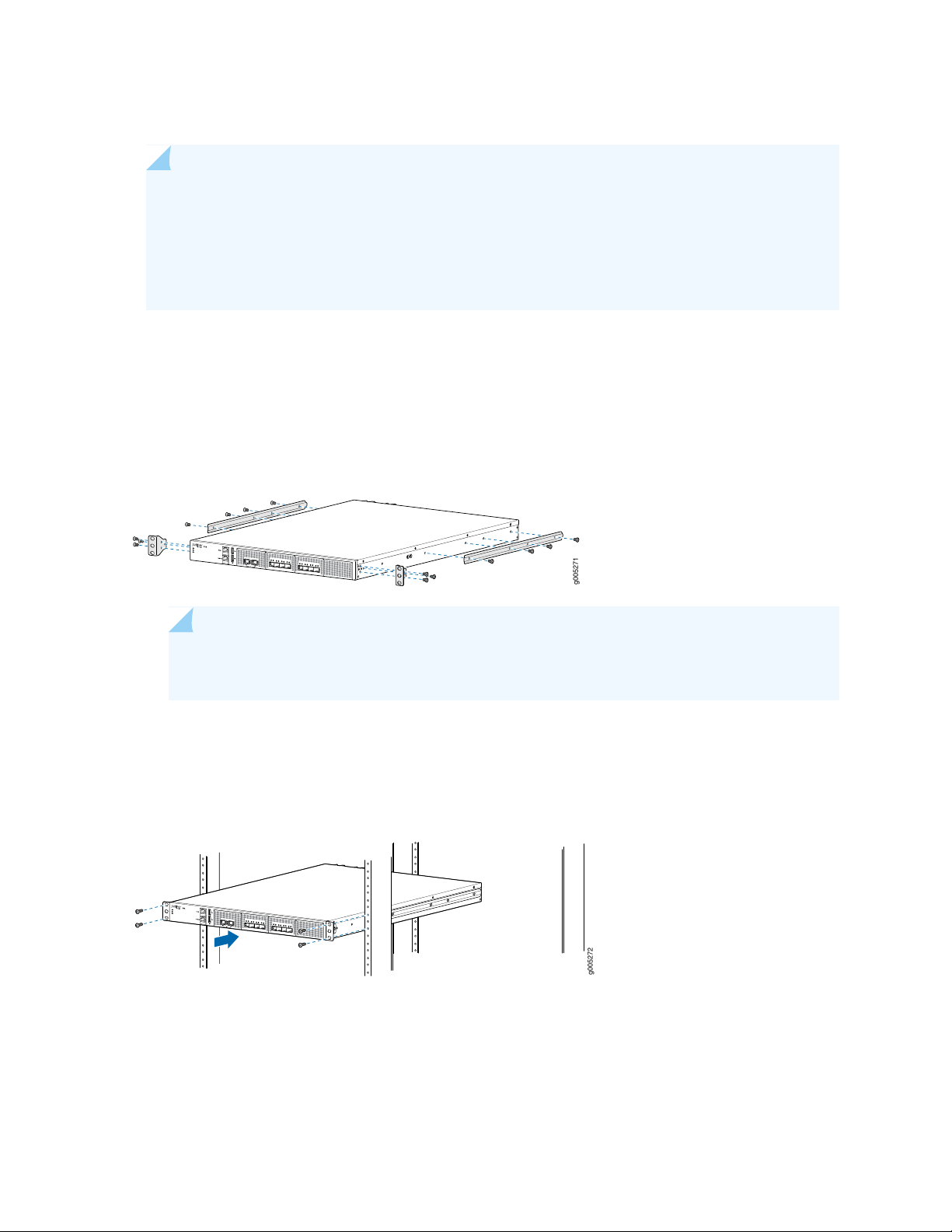
1. Attach the mounting ears to the front of the chassis, using the screws provided. Then, attach the fixed
brackets to the rear of the device, using the screws provided.
Figure 13: Attaching the Mounting Ears and Fixed Brackets
49
NOTE: Ensure that the rear of the device is supported throughout the process of mounting
the device into the rack.
2. Slide the device into the rack, and secure the mounting ears to the rack, using the mounting screws.
Figure 14: Securing the Mounting Ears to the Rack
3. Slide the adjustable brackets into the fixed brackets attached to the rear of the device.
Page 50
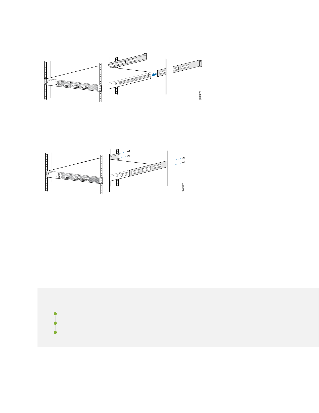
Figure 15: Attaching the Adjustable Brackets
g005273
g005274
4. Secure the adjustable brackets to the rack, using the mounting screws.
Figure 16: Securing the Adjustable Brackets to the Rack
50
RELATED DOCUMENTATION
Configuring Junos OS on the SRX4200 | 57
Connecting the SRX4200 to Power
IN THIS SECTION
Connecting the SRX4200 Services Gateway Grounding Cable | 51
Connecting AC Power to an SRX4200 Services Gateway | 52
Connecting DC Power to an SRX4200 Services Gateway | 54
Page 51

Connecting the SRX4200 Services Gateway Grounding Cable
To meet safety and electromagnetic interference (EMI) requirements and to ensure proper operation, the
services gateway must be adequately grounded before power is connected. You must provide a grounding
lug to connect the services gateway to earth ground.
You ground the services gateway by connecting a grounding cable to earth ground and then attaching it
to the chassis grounding point located on the back panel of the device using an M5 x 10 mm grounding
screw.
CAUTION: Before you connect power to the services gateway, a licensed electrician
must attach a cable lug to the grounding cable that you supply. A cable with an
incorrectly attached lug can damage the services gateway (for example, by causing a
short circuit).
51
Ensure that you have the following parts and tools available:
Electrostatic discharge (ESD) grounding wrist strap
•
Phillips (+) screwdriver, number 2
•
16 AWG single-strand wire grounding cable (green and yellow wire)
•
Grounding lug (ring-type, vinyl-insulated TV14-6R lug, or equivalent)
•
One metric M5 x 10 mm grounding screw
•
To connect the services gateway to earth ground:
1. Attach an electrostatic discharge (ESD) grounding strap to your bare wrist, and connect the strap to
the ESD point on the chassis.
2. Connect one end of the grounding cable to a proper earth ground, such as the rack in which the services
gateway is mounted.
3. Place the grounding lug attached to the grounding cable over the grounding point.
4. Secure the grounding cable lug to the grounding point with the screw. See Figure 17 on page 52.
Page 52

Figure 17: Connecting the Grounding Cable
5. Dress the grounding cable and verify that it does not touch or block access to the services gateway
components and that it does not drape where people could trip on it.
52
NOTE: When removing the chassis, turn off the power, and disconnect the grounding cable.
Connecting AC Power to an SRX4200 Services Gateway
Ensure that you have a power cord appropriate for your geographical location available to connect AC
power to an SRX4200 Services Gateway. Before you begin connecting AC power:
Ensure that you have taken the necessary precautions to prevent electrostatic discharge (ESD) damage.
•
Ensure that you have connected the device chassis to earth ground.
•
CAUTION: Before you connect power to the services gateway, a licensed electrician
must attach a cable lug to the grounding cable that you supply. A cable with an
incorrectly attached lug can damage the device (for example, by causing a short
circuit).
To meet safety and electromagnetic interference (EMI) requirements and to ensure
proper operation, you must properly ground the services gateway chassis before
connecting power.
Page 53
To connect AC power:
1. Attach an electrostatic discharge (ESD) grounding strap to your bare wrist, and connect the strap to
the ESD point on the rear of the chassis.
2. Ensure that the power supplies are fully inserted in the chassis and the latches are secure.
3. Locate the power cords shipped with the services gateway; the cords have plugs appropriate for your
geographical location.
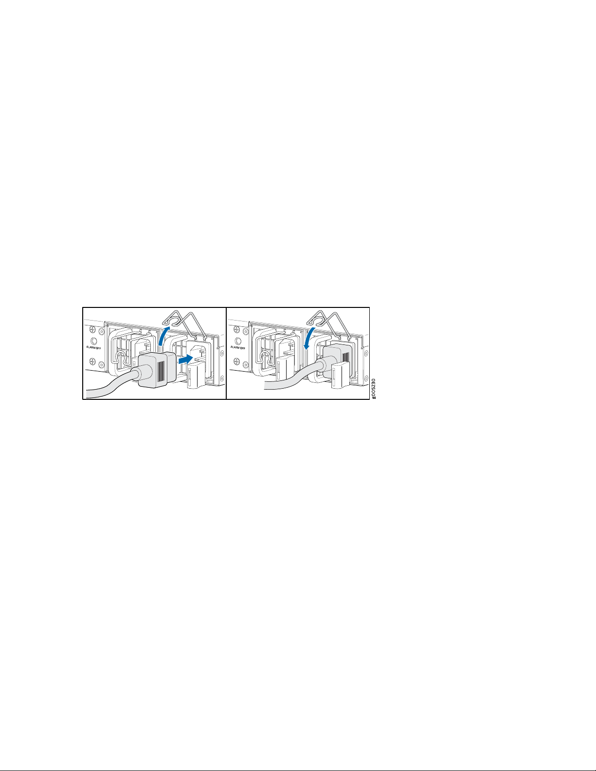
4. Insert the coupler end of the power cord into the AC power cord inlet on the AC power supply faceplate.
5. Push the power cord retainer onto the power cord. See Figure 18 on page 53.
Figure 18: Connecting AC Power
53
6. If the AC power source outlet has a power switch, set it to the off (0) position.
7. Insert the power cord plug into an AC power source outlet.
8. Dress the power cord appropriately. Verify that the power cord does not block the air exhaust and
access to services gateway components or drape where people could trip on it.
9. If the AC power source outlet has a power switch, set it to the on (|) position.
10. Repeat steps 4 through 8 for the second AC power supply.
11. Verify that the AC and DC LEDs on each power supply are lit green. If the fault status (!) LED is lit
amber, remove power from the power supply, and replace the power supply (see “Removing an AC
Power Supply from an SRX4200 Services Gateway” on page 63). Do not remove the power supply until
you have a replacement power supply ready. The power supplies must be installed in the services
gateway to ensure proper airflow.
Page 54

Connecting DC Power to an SRX4200 Services Gateway
Before you begin connecting DC power to an SRX4200 Services Gateway:
Ensure that you have taken the necessary precautions to prevent electrostatic discharge (ESD) damage.
•
Ensure that you have connected the chassis to earth ground.
•
CAUTION: Before you connect power to the services gateway, a licensed electrician
must attach a cable lug to the grounding cable that you supply. A cable with an
incorrectly attached lug can damage the device (for example, by causing a short
circuit).
To meet safety and electromagnetic interference (EMI) requirements and to ensure
proper operation, you must properly ground the services gateway chassis before
connecting power.
54
Ensure that you have the following parts and tools available:
DC power source cables (14–16 AWG) with ring lug (Molex 190700069 or equivalent)
•
Phillips (+) screwdriver, number 2
•
Multimeter
•
To connect DC power:
1. Attach an electrostatic discharge (ESD) grounding strap to your bare wrist, and connect the strap to
the ESD point on the rear of the chassis.
2. Verify that the DC power cables are correctly labeled before making connections to the power supply.
In a typical power distribution scheme where the return is connected to chassis ground at the battery
plant, you can use a multimeter to verify the resistance of the -48V and RTN DC cables to chassis
ground.
The cable with very high resistance (indicating an open circuit) to chassis ground is negative (–) and
•
will be installed on the V– (input) DC power input terminal.
The cable with very low resistance (indicating a closed circuit) to chassis ground is positive (+) and
•
will be installed on the V+ (return) DC power input terminal.
Page 55
CAUTION: You must ensure that power connections maintain the proper polarity.
The power source cables might be labeled (+) and (–) to indicate their polarity. There
is no standard color coding for DC power cables. The color coding used by the
external DC power source at your site determines the color coding for the leads
on the power cables that attach to the terminal studs on each power supply.
3. Ensure that the input circuit breaker is open so that the voltage across the DC power source cable
leads is 0 V and that the cable leads will not become active while you are connecting DC power.
4. Remove the terminal block cover. The terminal block cover is a piece of clear plastic that snaps into
place over the terminal block.
5. Remove the screws on the terminals using the screwdriver.
55
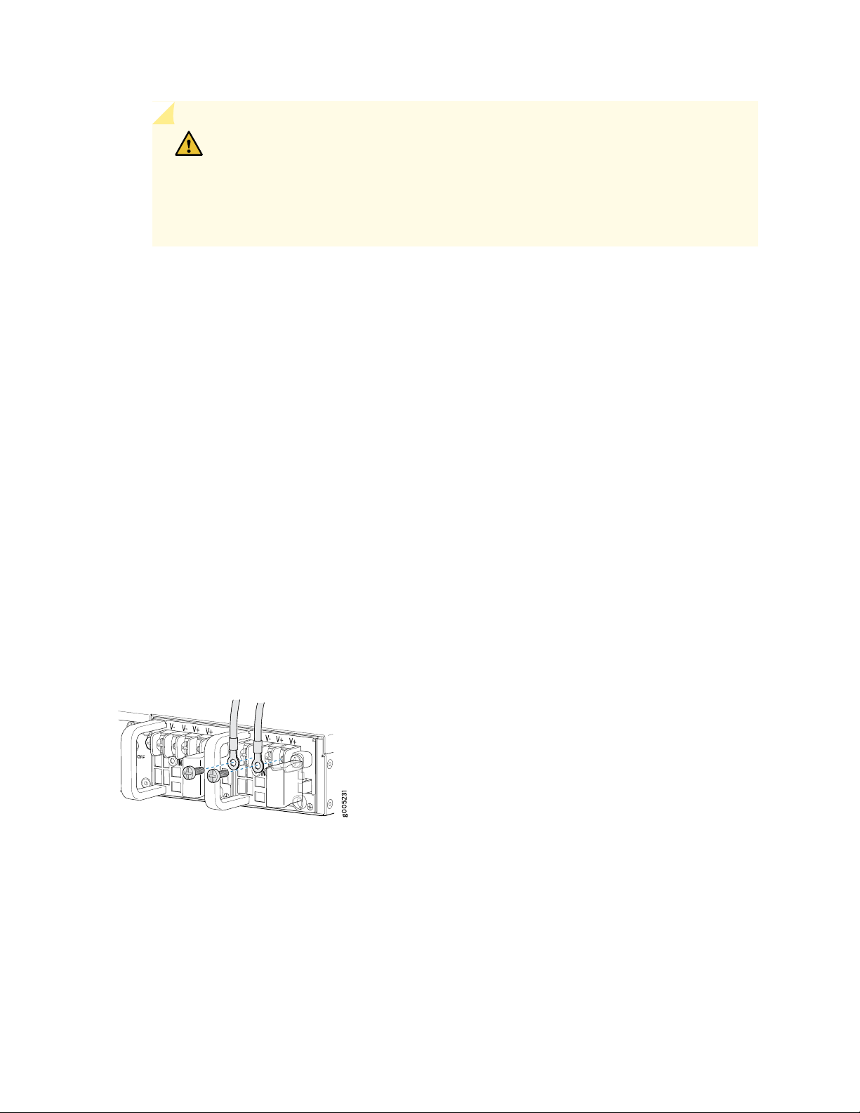
6. Connect each power supply to the power source. Secure power source cables to the power supplies
by screwing the ring lugs attached to the cables to the appropriate terminals by using the screw from
the terminals.
Secure the ring lug of the positive (+) DC power source cable to the V+ terminal on the DC power
•
supply.
Secure the ring lug of the negative (–) DC power source cable to the V– terminal on the DC power
•
supply.
Figure 19: Connecting DC Power
7. Tighten the screws on the power supply terminals until snug using the screwdriver. Do not overtighten.
8. Replace the terminal block cover.
9. Close the input circuit breaker.
Page 56

10. The device powers on as soon as power is provided to the power supply.
11. Verify that the IN and OUT LEDs on the power supply are lit green and are on steadily.
RELATED DOCUMENTATION
SRX4200 Power Supply | 25
Connecting the SRX4200 Services Gateway to a Management Console
Use the CONSOLE port on the services gateway to connect to a management console. The CONSOLE
port accepts a cable that has an RJ-45 connector.
56
To connect the services gateway to a management console:
1. Attach an electrostatic discharge (ESD) grounding strap to your bare wrist, and connect the strap to
the ESD point on the chassis.
2. Connect the RJ-45 end of the DB9-to-RJ-45 cable into the CONSOLE port on your services gateway.
3. Connect the other end of the cable to the serial port on the management device.
4. Start your asynchronous terminal emulation application (such as Microsoft Windows HyperTerminal)
and select the appropriate COM port to use (for example, COM1).
5. Configure the serial port settings:
Baud rate—9600
•
Parity—N
•
Data bits—8
•
Stop bits—1
•
Flow control—none
•
Page 57
Configuring Junos OS on the SRX4200
IN THIS SECTION
SRX4200 Services Gateway Software Configuration Overview | 57
SRX4200 Services Gateway Factory-Default Settings | 57
Viewing Factory-Default Settings | 58
Configuring the SRX4200 Services Gateway | 58
SRX4200 Services Gateway Software Configuration Overview
57
The services gateway is shipped with Junos OS preinstalled and ready to be configured when the services
gateway is powered on. If you are setting up the services gateway for the first time, use the CLI to perform
the initial configuration.
SRX4200 Services Gateway Factory-Default Settings
Your services gateway comes configured with a factory-default configuration.
Table 24 on page 57 and Table 25 on page 57 lists the factory-default settings.
Table 24: Factory-Default Settings - Interfaces
IP AddressInterface
192.168.1.1/24fxp0
Table 25: Factory-Default Settings - Services
Services
SSH
HTTPS
NETCONF over SSH
Page 58

Viewing Factory-Default Settings
To view the factory-default settings on your services gateway:
1. Log in as the root user and provide your credentials.
2. View the list of default configuration files:
user@host>file list /etc/config
3. View the required default configuration file.
user@host> file show /etc/config/<config file name>
When you commit changes to the configuration, a new configuration file is created, which becomes the
active configuration. If the current active configuration fails, you can use the load factory-default command
to revert to the factory-default configuration.
58
Configuring the SRX4200 Services Gateway
This procedure explains how you can create an initial configuration using CLI commands to connect the
services gateway to the network.
NOTE: Before you can use J-Web to configure your services gateway, you must access the CLI
to configure the root authentication.
1. Connect the RJ-45 end of the DB9-to-RJ-45 cable into the CONSOLE port on your services gateway.
2. Connect the other end of the cable to the serial port on the management device.
3. Log in to the services gateway as root. When the services gateway is powered on with the factory-default
configuration, you do not need to enter a password.
4. At the (%) prompt, type cli to start the CLI and press Enter. The prompt changes to an angle bracket
(>) when you enter CLI operational mode.
root%cli
Page 59

root>
5. At the (>) prompt, type configure and press Enter. The prompt changes from > to # when you enter
configuration mode.
root> configure
Entering configuration mode
[edit]
root#
6. Set the root authentication password by entering a cleartext password, an encrypted password, or an
SSH public key string (DSA or RSA).
[edit]
root# set system root-authentication plain-text-password
59
New password: password
Retype new password: password
7. Configure the route for the management interface (optional, required only if you do not connect the
MGMT port directly to the management device).
[edit]
root# set routing-options static route <destination prefix> next-hop <gateway>
8. Commit the configuration to activate it on the services gateway.
[edit]
root# commit
commit complete
9. Connect the MGMT port on the device to the Ethernet port on the management device using an RJ-45
cable.
10. Configure an IP address on the 192.168.1.0/24 subnetwork for the management device. By default,
the management interface is configured with the 192.168.1.1/24 IP address. If you need to change
the IP address, perform the following steps or else proceed to 11.
Page 60

a. Delete the default management interface IP address:
root# delete interface fxp0 unit 0 family inet address 192.168.1.1/24
b. Configure a new IP address for the management interface:
root# set interfaces fxp0 unit 0 family inet address address/prefix-length
c. Commit the configuration changes.
root# commit
d. Configure an IP address for the management device. Ensure that the IP address is on the same
subnetwork as the management interface (fxp0).
11. Launch a Web browser from the management device and access the services gateway using the URL
https://192.168.1.1.
If you changed the management interface IP address in 10, then use the URL https://<management IP
address> to access the services gateway.
60
NOTE: As the system-generated certificate is not trusted by default, an alert is displayed.
You can ignore this alert and proceed to access the services gateway.
The J-Web login page is displayed. This indicates that you have successfully completed the initial
configuration and that your services gateway is ready for use.
NOTE: To access the J-Web interface, your management device requires one of the following
supported browsers:
Microsoft Internet Explorer version 9.0 or 10.0
•
Mozilla Firefox version 38 (or later)
•
12. Log in as root and proceed with configuring the settings based on your requirements.
Page 61

4
CHAPTER
Maintaining Components
Routine Maintenance Procedures for the SRX4200 | 62
Maintaining the SRX4200 Power System | 62
Maintaining the SRX4200 Cooling System | 68
Page 62
Routine Maintenance Procedures for the SRX4200
For optimum performance of the services gateway, perform the following preventive maintenance
procedures regularly:
Inspect the installation site for moisture, loose wires or cables, and excessive dust.
•
Make sure that airflow is unobstructed around the services gateway and into the air intake vents. Make
•
sure that all power and grounding cables are arranged so that they do not obstruct access to other
services gateway components.
Check the status LEDs on the front panel of the services gateway.
•
Periodically inspect the site to ensure that the grounding and power cables connected to the services
•
gateway are securely in place and that there is no moisture accumulating near the services gateway.
62
RELATED DOCUMENTATION
Troubleshooting Resources for the SRX4200 Services Gateway | 71
Monitoring Chassis Alarms on a SRX4200 Services Gateway | 71
Maintaining the SRX4200 Power System
IN THIS SECTION
Replacing an AC Power Supply on the SRX4200 | 63
Replacing a DC Power Supply on the SRX4200 | 65
Page 63
Replacing an AC Power Supply on the SRX4200
IN THIS SECTION
Removing an AC Power Supply from an SRX4200 Services Gateway | 63
Installing an AC Power Supply in an SRX4200 Services Gateway | 64
The power supplies are hot-removable and hot-insertable field-replaceable units (FRUs) installed in the
rear panel of the services gateway. You can remove and replace them without powering off the services
gateway or disrupting services gateway functions.
Ensure that you have the following parts and tools available:
ESD grounding strap
•
63
Antistatic bag or an antistatic mat
•
Replacement power supply
•
Removing an AC Power Supply from an SRX4200 Services Gateway
To remove a power supply from the services gateway (see Figure 20 on page 64):
1. Place the antistatic bag or the antistatic mat on a flat, stable surface.
2. Attach an electrostatic discharge (ESD) grounding strap to your bare wrist and connect the strap to the
ESD point on the chassis.
3. If the AC power source outlet has a power switch, set it to the off (0) position and pull out the power
cord connected to the power source outlet.
4. Remove the power cord from the power supply faceplate.
5. Slide the ejector lever toward the left until the power supply is unseated.
6. Grasp the power supply handle and pull firmly to slide the power supply halfway out of the chassis.
7. Place one hand under the power supply to support it and slide it completely out of the chassis. Take
care not to touch power supply components, pins, leads, or solder connections.
Page 64
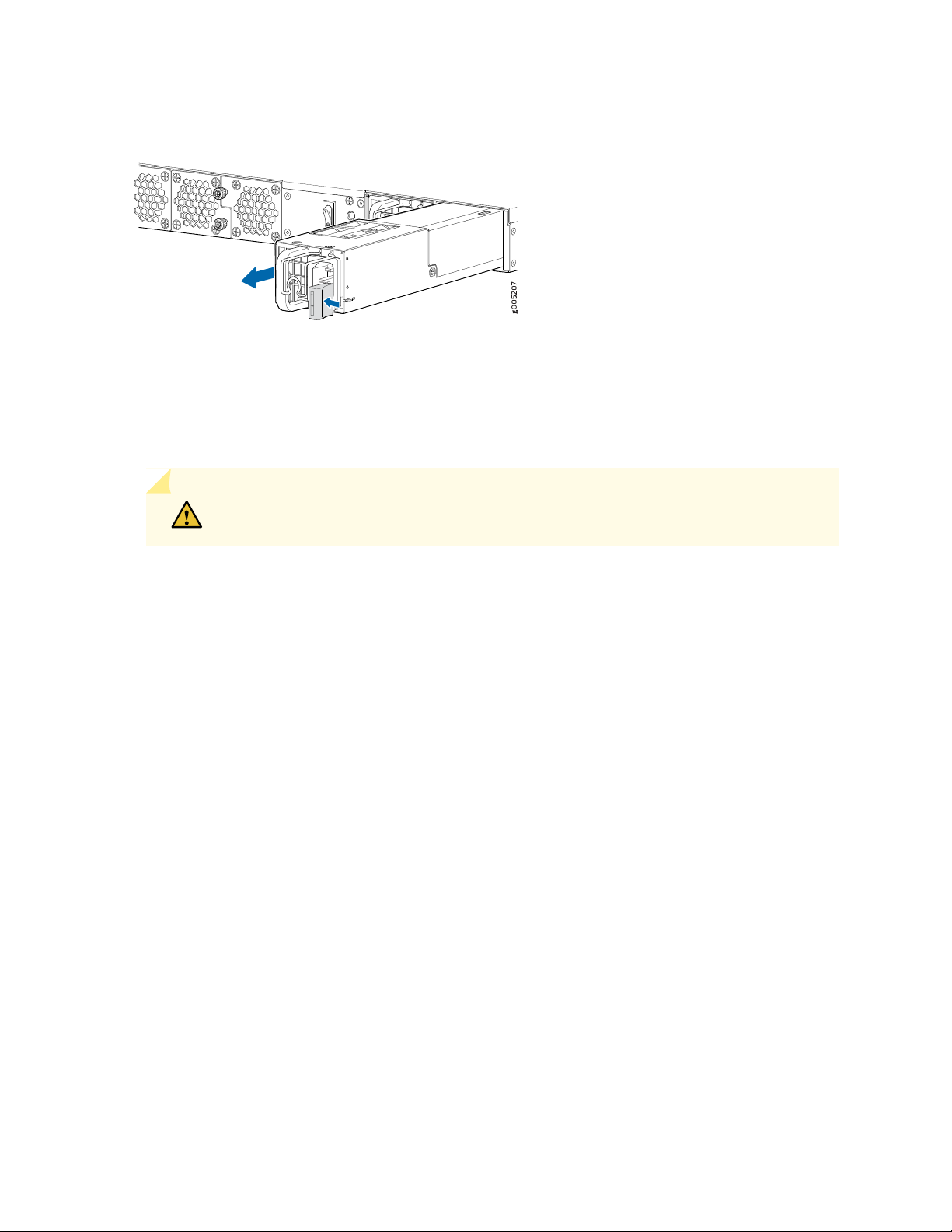
Figure 20: Removing an AC Power Supply
8. Place the power supply in the antistatic bag or on the antistatic mat placed on a flat, stable surface.
Installing an AC Power Supply in an SRX4200 Services Gateway
CAUTION: Do not mix AC and DC power supplies in the same chassis.
64
To install an AC power supply (see Figure 21 on page 65):
1. Attach the ESD grounding strap to your bare wrist, and connect the strap to the ESD point on the
chassis.
2. If the power supply slot has a cover panel on it, with one hand slide the ejector lever toward the left
until it stops and using the other hand pull the handle of the cover panel outward to remove it. Save
the cover panel for later use.
3. Taking care not to touch power supply pins, leads, or solder connections, remove the power supply
from the bag.
4. Using both hands, place the power supply in the power supply slot on the rear panel of the services
gateway and slide it in until it is fully seated and the ejector lever fits into place. You will hear a distinct
click when the power supply is fully seated in the chassis.
Page 65
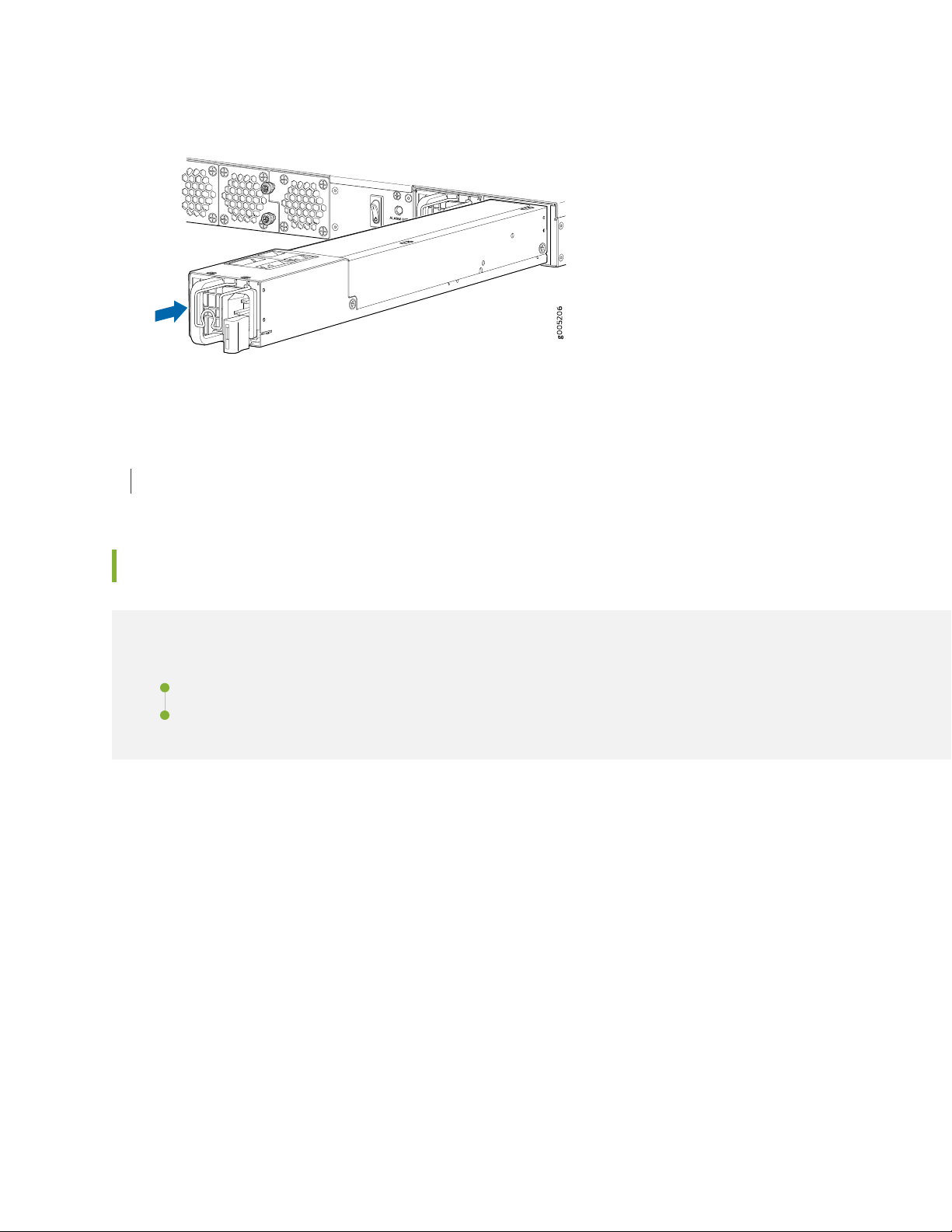
Figure 21: Installing an AC Power Supply
SEE ALSO
Connecting AC Power to an SRX4200 Services Gateway | 52
65
Replacing a DC Power Supply on the SRX4200
IN THIS SECTION
Removing a DC Power Supply from an SRX4200 Services Gateway | 66
Installing a DC Power Supply in an SRX4200 Services Gateway | 67
The power supplies are hot-removable and hot-insertable field-replaceable units (FRUs) installed in the
rear panel of the services gateway. You can remove and replace them without powering off the services
gateway or disrupting services gateway functions.
Ensure that you have the following parts and tools available:
ESD grounding strap
•
Phillips (+) screwdriver, number 2
•
Antistatic bag or an antistatic mat
•
Replacement power supply
•
Page 66
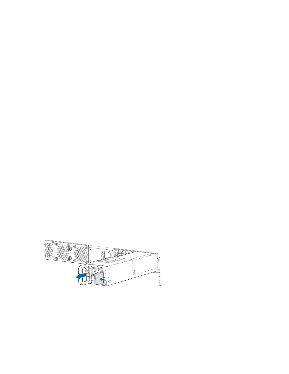
Removing a DC Power Supply from an SRX4200 Services Gateway
g0052 0 9
To remove a DC power supply (see Figure 22 on page 66):
1. Place the antistatic bag or the antistatic mat on a flat, stable surface.
2. Attach the ESD grounding strap to your bare wrist, and connect the strap to the ESD point on the
chassis.
3. Make sure that the voltage across the DC power source cables leads is 0 V and that there is no chance
that the cables might become active during the removal process.
4. Remove the plastic cover from the input terminals by sliding the cover either to the left or right.
5. Unscrew the locking screws counterclockwise by using the screwdriver.
6. Remove the cable lugs from the input DC terminals.
66
7. Slide the ejector lever toward the left until the power supply is unseated.
8. Grasp the power supply handle and pull firmly to slide the power supply halfway out of the chassis.
9. Taking care not to touch power supply pins, leads, or solder connections, place one hand under the
power supply to support it. Grasp the power supply handle with your other hand and pull the power
supply completely out of the chassis.
Figure 22: Removing a DC Power Supply
10. Place the power supply in the antistatic bag or on the antistatic mat placed on a flat, stable surface.
Page 67
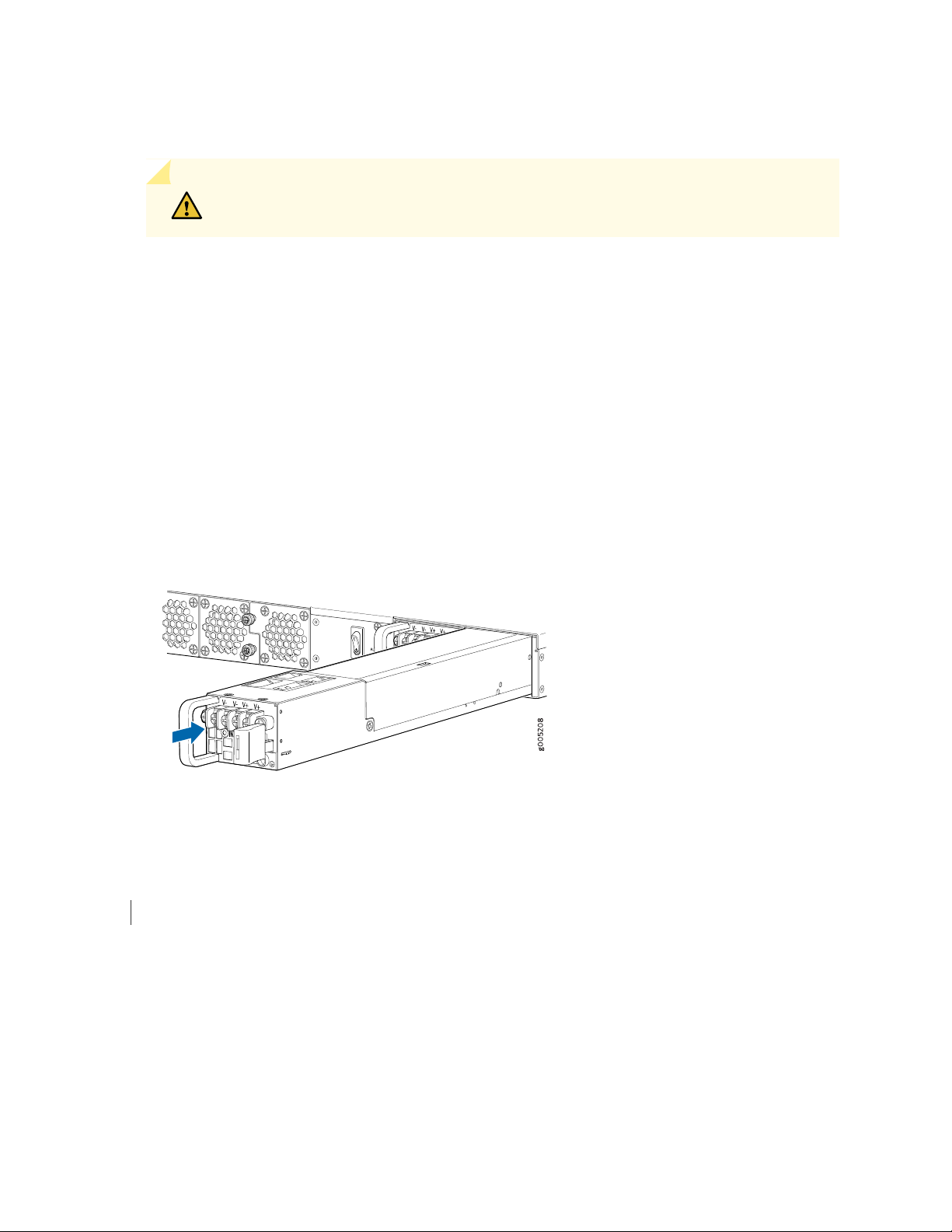
Installing a DC Power Supply in an SRX4200 Services Gateway
CAUTION: Do not mix AC and DC power supplies in the same chassis.
To install a DC power supply (see Figure 23 on page 67):
1. Attach the ESD grounding strap to your bare wrist, and connect the strap to the ESD point on the
chassis.
2. Taking care not to touch power supply pins, leads, or solder connections, remove the power supply
from the bag.
3. Using both hands, place the power supply in the power supply slot on the rear panel of the services
gateway and slide it in until it is fully seated and the ejector lever fits into place. You will hear a distinct
click when the power supply is fully seated in the chassis.
67
Figure 23: Installing a DC Power Supply
SEE ALSO
Connecting DC Power to an SRX4200 Services Gateway | 54
Page 68
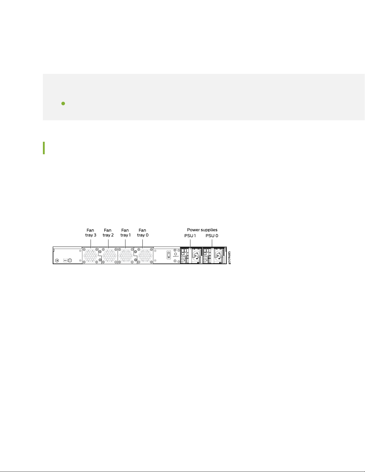
Maintaining the SRX4200 Cooling System
IN THIS SECTION
Replacing the SRX4200 Services Gateway Fan Tray | 68
Replacing the SRX4200 Services Gateway Fan Tray
To replace the fan tray:
1. Identify the physical location of the faulty fan tray on the rear panel of the chassis. Figure 24 on page 68
shows how the fan trays are numbered.
68
Figure 24: SRX4200 Services Gateway Fan Tray Numbering
2. Attach an electrostatic discharge (ESD) grounding strap to your bare wrist, and connect the strap to
the ESD point on the chassis.
3. Loosen the captive screws on the fan tray faceplate.
4. Grasp the captive screw and pull out the fan tray completely out of the chassis.
5. Insert the replacement fan tray straight into the chassis.
6. Tighten the captive screw on the fan tray faceplate to secure it in the chassis.
RELATED DOCUMENTATION
Page 69

SRX4200 Cooling System | 23
69
Page 70

5
CHAPTER
Troubleshooting Hardware
Troubleshooting the SRX4200 | 71
Page 71
Troubleshooting the SRX4200
IN THIS SECTION
Troubleshooting Resources for the SRX4200 Services Gateway | 71
Monitoring Chassis Alarms on a SRX4200 Services Gateway | 71
Using the RESET Button on the SRX4200 Services Gateway | 73
Troubleshooting Resources for the SRX4200 Services Gateway
To troubleshoot a services gateway, use the Junos OS command-line interface (CLI) and LEDs on the
chassis:
71
LEDs—When the services gateway detects an alarm condition, the status LED on the front panel glows
•
red.
CLI—The CLI is the primary tool for controlling and troubleshooting hardware, Junos OS, and network
•
connectivity. Use the CLI to display more information about alarms. CLI commands display information
about network connectivity derived from the ping and traceroute utilities. For information about using
the CLI to troubleshoot Junos OS, see the appropriate Junos OS configuration guide.
JTAC—If you need assistance during troubleshooting, you can contact the Juniper Networks Technical
•
Assistance Center (JTAC) by using the Web or by telephone. If you encounter software problems, or
problems with hardware components not discussed here, contact JTAC.
Monitoring Chassis Alarms on a SRX4200 Services Gateway
You can monitor chassis alarms through the Status LED. When the services gateway detects an alarm
condition, the Status LED on the front panel glows red. The level of severity can be either major (steady
red) or minor (blinking red). To view a more detailed description of the alarm cause, issue the show chassis
alarms command.
Table 26 on page 72 describes alarms that can occur for the services gateway chassis component.
Page 72

Table 26: Alarms for Services Gateway Chassis Components
72
Alarm SeverityActionAlarm ConditionsComponent
Fan
At least one of the fans
have failed.
The services gateway
chassis temperature is too
warm.
Check and adjust the room
•
temperature, if possible.
Check the air flow and ensure
•
that the airflow through the
services gateway is
unobstructed.
Open a support case using the
•
Case Manager link at
https://www.juniper.net/support/
or call 1-888-314-5822
(toll-free within the United
States and Canada) or
1-408-745-9500 (from outside
the United States).
Check the room temperature.
•
Check the air flow.
•
Open a support case using the
•
Case Manager link at
https://www.juniper.net/support/
or call 1-888-314-5822
(toll-free within the United
States and Canada) or
1-408-745-9500 (from outside
the United States).
Steady red (major)
Yellow (minor)
A power supply unit is not
present.
AC power cord is not
connected.
Steady red (major)Replace the power supply.A power supply has failed.Power supply
Install a power supply unit in the
empty slot. The services gateway
requires two power supply units
to be installed.
Verify and ensure that the AC
power cord is connected
properly.
Page 73
Using the RESET Button on the SRX4200 Services Gateway
If a configuration fails or denies management access to the services gateway, you can use the RESET
button to restore the services gateway to the factory-default configuration.
CAUTION: Pressing and holding the RESET button for 5 seconds or more deletes all
configurations (backup configurations and rescue configuration) on the device, and
loads and commits the factory configuration.
You can change the default operation of the RESET button by limiting how the button resets the services
gateway:
To prevent the RESET button from setting the services gateway to the factory-default configuration
•
and deleting all other configurations, enter the following command. You can still press and quickly release
the button to reset it to the rescue configuration.
73
user@host# set chassis config-button no-clear
To prevent the RESET button from setting the services gateway to the rescue configuration, enter the
•
following command. You can still press and hold the button for 15 seconds or more to reset the services
gateway to the factory-default configuration.
user@host# set chassis config-button no-rescue
To disable the button and prevent the services gateway from resetting to either configuration, enter the
•
following command:
user@host# set chassis config-button no-clear no-rescue
The no-rescue option prevents the RESET button from loading the rescue configuration. The no-clear
option prevents the RESET button from deleting all configurations on the services gateway.
To return the function of the RESET button to its default behavior, remove the config-button statement
from the services gateway configuration.
RELATED DOCUMENTATION
SRX4200 Services Gateway Front Panel | 19
Page 74

6
CHAPTER
Contacting Customer Support and
Returning the Chassis or Components
Returning the SRX4200 Chassis or Components | 75
Page 75
Returning the SRX4200 Chassis or Components
IN THIS SECTION
Contacting Customer Support | 75
Returning a SRX4200 Services Gateway or Component to Juniper Networks | 76
Locating the Serial Number on the SRX4200 Services Gateway or Component | 77
Packing a SRX4200 Services Gateway or Component for Shipping | 78
Contacting Customer Support
75
Once you have located the serial numbers of the device or component, you can return the device or
component for repair or replacement. For this, you need to contact Juniper Networks Technical Assistance
Center (JTAC).
You can contact JTAC 24 hours a day, 7 days a week, using any of the following methods:
On the Web: Using the Service Request Manager link at https://support.juniper.net/support/
•
By telephone:
•
From the US and Canada: 1-888-314-JTAC
•
From all other locations: 1-408-745-9500
•
NOTE: If contacting JTAC by telephone, enter your 12-digit service request number followed
by the pound (#) key if this is an existing case, or press the star (*) key to be routed to the
next available support engineer.
When requesting support from JTAC by telephone, be prepared to provide the following information:
Your existing service request number, if you have one
•
Details of the failure or problem
•
Type of activity being performed on the services gateway when the problem occurred
•
Configuration data displayed by one or more show commands
•
Your name, organization name, telephone number, fax number, and shipping address
•
Page 76

The support representative validates your request and issues a Return Materials Authorization (RMA)
number for return of the device or component.
Returning a SRX4200 Services Gateway or Component to Juniper Networks
To return a services gateway or component to Juniper Networks for repair or replacement, follow this
procedure:
1. Determine the part number and serial number of the services gateway or component. See “Locating
the Serial Number on the SRX4200 Services Gateway or Component” on page 77.
2. Obtain a Return Materials Authorization (RMA) number from JTAC. See “Contacting Customer Support”
on page 75.
NOTE: Do not return the services gateway or any component to Juniper Networks unless
you have first obtained an RMA number. Juniper Networks reserves the right to refuse
shipments that do not have an RMA. Refused shipments are returned to the customer via
collect freight.
76
3. Pack the services gateway or component for shipping.
For more information about return and repair policies, see the customer support webpage at
https://www.juniper.net/support/guidelines.html.
For product problems or technical support issues, open a support case using the Case Manager link at
https://www.juniper.net/support/ or call 1-888-314-JTAC (within the United States) or 1-408-745-9500
(outside the United States).
Page 77
Locating the Serial Number on the SRX4200 Services Gateway or Component
IN THIS SECTION
Listing the SRX4200 Services Gateway Component Details with the CLI | 77
Locating the Chassis Serial Number ID Label | 78
Locating the Serial Number ID Labels on FRUs | 78
If you are returning a services gateway or hardware component to Juniper Networks for repair or
replacement, you must locate the serial number of the services gateway or component. You must provide
the serial number to the Juniper Networks Technical Assistance Center (JTAC) when you contact them to
obtain Return Materials Authorization (RMA).
77
If the services gateway is operational and you can access the CLI, you can list serial numbers for the services
gateway and for some components with a CLI command. If you do not have access to the CLI or if the
serial number for the component does not appear in the command output, you can locate the serial number
ID label on the physical device or component.
Listing the SRX4200 Services Gateway Component Details with the CLI
Before contacting Juniper Networks to request a Return Materials Authorization (RMA), you must find
the serial number on the SRX4200 Services Gateway or component. To list all the SRX4200 Services
Gateway components and their serial numbers, enter the following CLI command:
user@host> show chassis hardware
Hardware inventory:
Item Version Part number Serial number Description
Chassis DK2716AR0033 SRX4200
Mainboard REV 01 650-071675 16061032276 SRX4200
Routing Engine 0 BUILTIN BUILTIN SRX Routing Engine
FPC 0 BUILTIN BUILTIN FEB
PIC 0 BUILTIN BUILTIN 8x10G-SFP
Xcvr 0 REV 01 740-021309 L16G12897 SFP+-10G-LR
Xcvr 1 REV 01 740-021309 66T027400944 SFP+-10G-LR
Xcvr 2 REV 01 740-021309 ATN0CDU SFP+-10G-LR
Xcvr 3 REV 01 740-021309 66T027400946 SFP+-10G-LR
Page 78

Xcvr 4 REV 01 740-021308 CG05KM0JB SFP+-10G-SR
Xcvr 5 REV 01 740-021309 66T027400949 SFP+-10G-LR
Xcvr 6 REV 01 740-021308 CG06KM08N SFP+-10G-SR
Xcvr 7 REV 01 740-021308 CG06KM086 SFP+-10G-SR
Power Supply 0 REV 04 740-041741 1GA26241738 JPSU-650W-AC-AFO
Power Supply 1 REV 04 740-041741 1GA26241716 JPSU-650W-AC-AFO
Fan Tray 0 SRX4200 0, Front to Back
Airflow - AFO
Fan Tray 1 SRX4200 1, Front to Back
Airflow - AFO
Fan Tray 2 SRX4200 2, Front to Back
Airflow - AFO
Fan Tray 3 SRX4200 3, Front to Back
Airflow - AFO
78
Locating the Chassis Serial Number ID Label
The serial number ID label is located on the rear panel of the services gateway.
Locating the Serial Number ID Labels on FRUs
The power supplies installed in the services gateway are field-replaceable units (FRUs). The serial number
ID label is on the top of the power supply.
Packing a SRX4200 Services Gateway or Component for Shipping
IN THIS SECTION
Packing the SRX4200 Services Gateway for Shipment | 79
Packing the SRX4200 Services Gateway Components for Shipment | 80
Before you pack a SRX4200 Services Gateway or component:
Ensure that you have taken the necessary precautions to prevent electrostatic discharge (ESD) damage.
•
Page 79

Retrieve the original shipping carton and packing materials. Contact your JTAC representative if you do
•
not have these materials, to learn about approved packing materials. See “Contacting Customer Support”
on page 75.
Ensure that you have the following parts and tools available:
ESD grounding strap
•
Antistatic bag, one for each component
•
Phillips (+) screwdriver, number 2
•
Packing the SRX4200 Services Gateway for Shipment
To pack the services gateway for shipment:
1. Attach an electrostatic discharge (ESD) grounding strap to your bare wrist and connect the strap to the
ESD point on the chassis or to an outside ESD point if the device is disconnected from earth ground.
.
79
2. On the console or other management device connected to the services gateway, enter CLI operational
mode and issue the following command to shut down the services gateway software:
user@host> request system halt
Wait until a message appears on the console confirming that the operating system has halted.
3. Shut down power to the services gateway by pressing the Power switch on the rear of the services
gateway.
4. Disconnect power from the services gateway.
5. Remove the cables that connect to all external devices.
6. If the services gateway is installed in a rack, have one person support the weight of the services gateway
while another person unscrews and removes the mounting screws.
7. Place the services gateway in the shipping carton.
8. Cover the services gateway with an ESD bag, and place the packing foam on top of and around the
device.
9. Replace the accessory box on top of the packing foam.
Page 80
10. Securely tape the box closed.
11. Write the Return Materials Authorization (RMA) number on the exterior of the box to ensure proper
tracking.
Packing the SRX4200 Services Gateway Components for Shipment
Follow these guidelines for packing and shipping individual components of the services gateway:
When you return a component, make sure that it is adequately protected with packing materials and
•
packed so that the pieces are prevented from moving around inside the carton.
Use the original shipping materials if they are available.
•
Place the individual component in an electrostatic bag.
•
Write the Return Materials Authorization (RMA) number on the exterior of the box to ensure proper
•
tracking.
80
CAUTION: Do not stack any of the services gateway components during packing.
Page 81

7
CHAPTER
Safety and Compliance Information
General Safety Guidelines and Warnings | 83
Definitions of Safety Warning Levels | 84
Restricted Access Warning | 88
Qualified Personnel Warning | 91
Prevention of Electrostatic Discharge Damage | 91
Fire Safety Requirements | 93
Laser and LED Safety Guidelines and Warnings | 94
Radiation from Open Port Apertures Warning | 99
Maintenance and Operational Safety Guidelines and Warnings | 100
General Electrical Safety Guidelines and Warnings | 108
AC Power Electrical Safety Guidelines | 114
DC Power Electrical Safety Guidelines | 114
DC Power Disconnection Warning | 116
DC Power Grounding Requirements and Warning | 118
DC Power Wiring Sequence Warning | 120
Page 82

DC Power Wiring Terminations Warning | 123
Action to Take After an Electrical Accident | 125
Agency Approvals | 125
Acoustic Noise Compliance Statements | 127
EMC Requirements | 127
Statements of Volatility for Juniper Network Devices | 129
Page 83

General Safety Guidelines and Warnings
The following guidelines help ensure your safety and protect the device from damage. The list of guidelines
might not address all potentially hazardous situations in your working environment, so be alert and exercise
good judgment at all times.
Perform only the procedures explicitly described in the hardware documentation for this device. Make
•
sure that only authorized service personnel perform other system services.
Keep the area around the device clear and free from dust before, during, and after installation.
•
Keep tools away from areas where people could trip over them while walking.
•
Do not wear loose clothing or jewelry, such as rings, bracelets, or chains, which could become caught
•
in the device.
Wear safety glasses if you are working under any conditions that could be hazardous to your eyes.
•
Do not perform any actions that create a potential hazard to people or make the equipment unsafe.
•
83
Never attempt to lift an object that is too heavy for one person to handle.
•
Never install or manipulate wiring during electrical storms.
•
Never install electrical jacks in wet locations unless the jacks are specifically designed for wet
•
environments.
Operate the device only when it is properly grounded.
•
Follow the instructions in this guide to properly ground the device to earth.
•
Replace fuses only with fuses of the same type and rating.
•
Do not open or remove chassis covers or sheet-metal parts unless instructions are provided in the
•
hardware documentation for this device. Such an action could cause severe electrical shock.
Do not push or force any objects through any opening in the chassis frame. Such an action could result
•
in electrical shock or fire.
Avoid spilling liquid onto the chassis or onto any device component. Such an action could cause electrical
•
shock or damage the device.
Avoid touching uninsulated electrical wires or terminals that have not been disconnected from their
•
power source. Such an action could cause electrical shock.
Some parts of the chassis, including AC and DC power supply surfaces, power supply unit handles, SFB
•
card handles, and fan tray handles might become hot. The following label provides the warning of the
hot surfaces on the chassis:
Page 84
Always ensure that all modules, power supplies, and cover panels are fully inserted and that the installation
•
screws are fully tightened.
Definitions of Safety Warning Levels
The documentation uses the following levels of safety warnings (there are two Warning formats):
NOTE: You might find this information helpful in a particular situation, or you might overlook
this important information if it was not highlighted in a Note.
84
CAUTION: You need to observe the specified guidelines to prevent minor injury or
discomfort to you or severe damage to the device.
Attention Veillez à respecter les consignes indiquées pour éviter toute incommodité
ou blessure légère, voire des dégâts graves pour l’appareil.
WARNING: This symbol alerts you to the risk of personal injury from a laser.
Avertissement Ce symbole signale un risque de blessure provoquée par rayon laser.
Page 85

85
Page 86

WARNING: This symbol means danger. You are in a situation that could cause bodily
injury. Before you work on any equipment, be aware of the hazards involved with
electrical circuitry and be familiar with standard practices for preventing accidents.
Waarschuwing Dit waarschuwingssymbool betekent gevaar. U verkeert in een situatie
die lichamelijk letsel kan veroorzaken. Voordat u aan enige apparatuur gaat werken,
dient u zich bewust te zijn van de bij elektrische schakelingen betrokken risico's en
dient u op de hoogte te zijn van standaard maatregelen om ongelukken te voorkomen.
Varoitus Tämä varoitusmerkki merkitsee vaaraa. Olet tilanteessa, joka voi johtaa
ruumiinvammaan. Ennen kuin työskentelet minkään laitteiston parissa, ota selvää
sähkökytkentöihin liittyvistä vaaroista ja tavanomaisista onnettomuuksien
ehkäisykeinoista.
Avertissement Ce symbole d'avertissement indique un danger. Vous vous trouvez
dans une situation pouvant causer des blessures ou des dommages corporels. Avant
de travailler sur un équipement, soyez conscient des dangers posés par les circuits
électriques et familiarisez-vous avec les procédures couramment utilisées pour éviter
les accidents.
86
Warnung Dieses Warnsymbol bedeutet Gefahr. Sie befinden sich in einer Situation,
die zu einer Körperverletzung führen könnte. Bevor Sie mit der Arbeit an irgendeinem
Gerät beginnen, seien Sie sich der mit elektrischen Stromkreisen verbundenen Gefahren
und der Standardpraktiken zur Vermeidung von Unfällen bewußt.
Avvertenza Questo simbolo di avvertenza indica un pericolo. La situazione potrebbe
causare infortuni alle persone. Prima di lavorare su qualsiasi apparecchiatura, occorre
conoscere i pericoli relativi ai circuiti elettrici ed essere al corrente delle pratiche
standard per la prevenzione di incidenti.
Advarsel Dette varselsymbolet betyr fare. Du befinner deg i en situasjon som kan føre
til personskade. Før du utfører arbeid på utstyr, må du vare oppmerksom på de
faremomentene som elektriske kretser innebærer, samt gjøre deg kjent med vanlig
praksis når det gjelder å unngå ulykker.
Aviso Este símbolo de aviso indica perigo. Encontra-se numa situação que lhe poderá
causar danos físicos. Antes de começar a trabalhar com qualquer equipamento,
familiarize-se com os perigos relacionados com circuitos eléctricos, e com quaisquer
práticas comuns que possam prevenir possíveis acidentes.
¡Atención! Este símbolo de aviso significa peligro. Existe riesgo para su integridad física.
Antes de manipular cualquier equipo, considerar los riesgos que entraña la corriente
eléctrica y familiarizarse con los procedimientos estándar de prevención de accidentes.
Page 87

Varning! Denna varningssymbol signalerar fara. Du befinner dig i en situation som kan
leda till personskada. Innan du utför arbete på någon utrustning måste du vara medveten
om farorna med elkretsar och känna till vanligt förfarande för att förebygga skador.
87
Page 88

Restricted Access Warning
88
Page 89

WARNING: This unit is intended for installation in restricted access areas. A restricted
access area is an area to which access can be gained only by service personnel through
the use of a special tool, lock and key, or other means of security, and which is
controlled by the authority responsible for the location.
Waarschuwing Dit toestel is bedoeld voor installatie op plaatsen met beperkte toegang.
Een plaats met beperkte toegang is een plaats waar toegang slechts door
servicepersoneel verkregen kan worden door middel van een speciaal instrument, een
slot en sleutel, of een ander veiligheidsmiddel, en welke beheerd wordt door de
overheidsinstantie die verantwoordelijk is voor de locatie.
Varoitus Tämä laite on tarkoitettu asennettavaksi paikkaan, johon pääsy on rajoitettua.
Paikka, johon pääsy on rajoitettua, tarkoittaa paikkaa, johon vain huoltohenkilöstö
pääsee jonkin erikoistyökalun, lukkoon sopivan avaimen tai jonkin muun turvalaitteen
avulla ja joka on paikasta vastuussa olevien toimivaltaisten henkilöiden valvoma.
Avertissement Cet appareil est à installer dans des zones d'accès réservé. Ces dernières
sont des zones auxquelles seul le personnel de service peut accéder en utilisant un
outil spécial, un mécanisme de verrouillage et une clé, ou tout autre moyen de sécurité.
L'accès aux zones de sécurité est sous le contrôle de l'autorité responsable de
l'emplacement.
89
Warnung Diese Einheit ist zur Installation in Bereichen mit beschränktem Zutritt
vorgesehen. Ein Bereich mit beschränktem Zutritt ist ein Bereich, zu dem nur
Wartungspersonal mit einem Spezialwerkzeugs, Schloß und Schlüssel oder anderer
Sicherheitsvorkehrungen Zugang hat, und der von dem für die Anlage zuständigen
Gremium kontrolliert wird.
Avvertenza Questa unità deve essere installata in un'area ad accesso limitato. Un'area
ad accesso limitato è un'area accessibile solo a personale di assistenza tramite
un'attrezzo speciale, lucchetto, o altri dispositivi di sicurezza, ed è controllata
dall'autorità responsabile della zona.
Advarsel Denne enheten er laget for installasjon i områder med begrenset adgang. Et
område med begrenset adgang gir kun adgang til servicepersonale som bruker et
spesielt verktøy, lås og nøkkel, eller en annen sikkerhetsanordning, og det kontrolleres
av den autoriteten som er ansvarlig for området.
Aviso Esta unidade foi concebida para instalação em áreas de acesso restrito. Uma
área de acesso restrito é uma área à qual apenas tem acesso o pessoal de serviço
autorizado, que possua uma ferramenta, chave e fechadura especial, ou qualquer outra
forma de segurança. Esta área é controlada pela autoridade responsável pelo local.
Page 90

¡Atención! Esta unidad ha sido diseñada para instalarse en áreas de acceso restringido.
Área de acceso restringido significa un área a la que solamente tiene acceso el personal
de servicio mediante la utilización de una herramienta especial, cerradura con llave, o
algún otro medio de seguridad, y que está bajo el control de la autoridad responsable
del local.
Varning! Denna enhet är avsedd för installation i områden med begränsat tillträde. Ett
område med begränsat tillträde får endast tillträdas av servicepersonal med ett speciellt
verktyg, lås och nyckel, eller annan säkerhetsanordning, och kontrolleras av den
auktoritet som ansvarar för området.
90
Page 91

Qualified Personnel Warning
WARNING: Only trained and qualified personnel should install or replace the device.
Waarschuwing Installatie en reparaties mogen uitsluitend door getraind en bevoegd
personeel uitgevoerd worden.
Varoitus Ainoastaan koulutettu ja pätevä henkilökunta saa asentaa tai vaihtaa tämän
laitteen.
Avertissement Tout installation ou remplacement de l'appareil doit être réalisé par du
personnel qualifié et compétent.
Warnung Gerät nur von geschultem, qualifiziertem Personal installieren oder
auswechseln lassen.
Avvertenza Solo personale addestrato e qualificato deve essere autorizzato ad installare
o sostituire questo apparecchio.
91
Advarsel Kun kvalifisert personell med riktig opplæring bør montere eller bytte ut dette
utstyret.
Aviso Este equipamento deverá ser instalado ou substituído apenas por pessoal
devidamente treinado e qualificado.
¡Atención! Estos equipos deben ser instalados y reemplazados exclusivamente por
personal técnico adecuadamente preparado y capacitado.
Varning! Denna utrustning ska endast installeras och bytas ut av utbildad och
kvalificerad personal.
Prevention of Electrostatic Discharge Damage
Device components that are shipped in antistatic bags are sensitive to damage from static electricity. Some
components can be impaired by voltages as low as 30 V. You can easily generate potentially damaging
static voltages whenever you handle plastic or foam packing material or if you move components across
plastic or carpets. Observe the following guidelines to minimize the potential for electrostatic discharge
(ESD) damage, which can cause intermittent or complete component failures:
Page 92
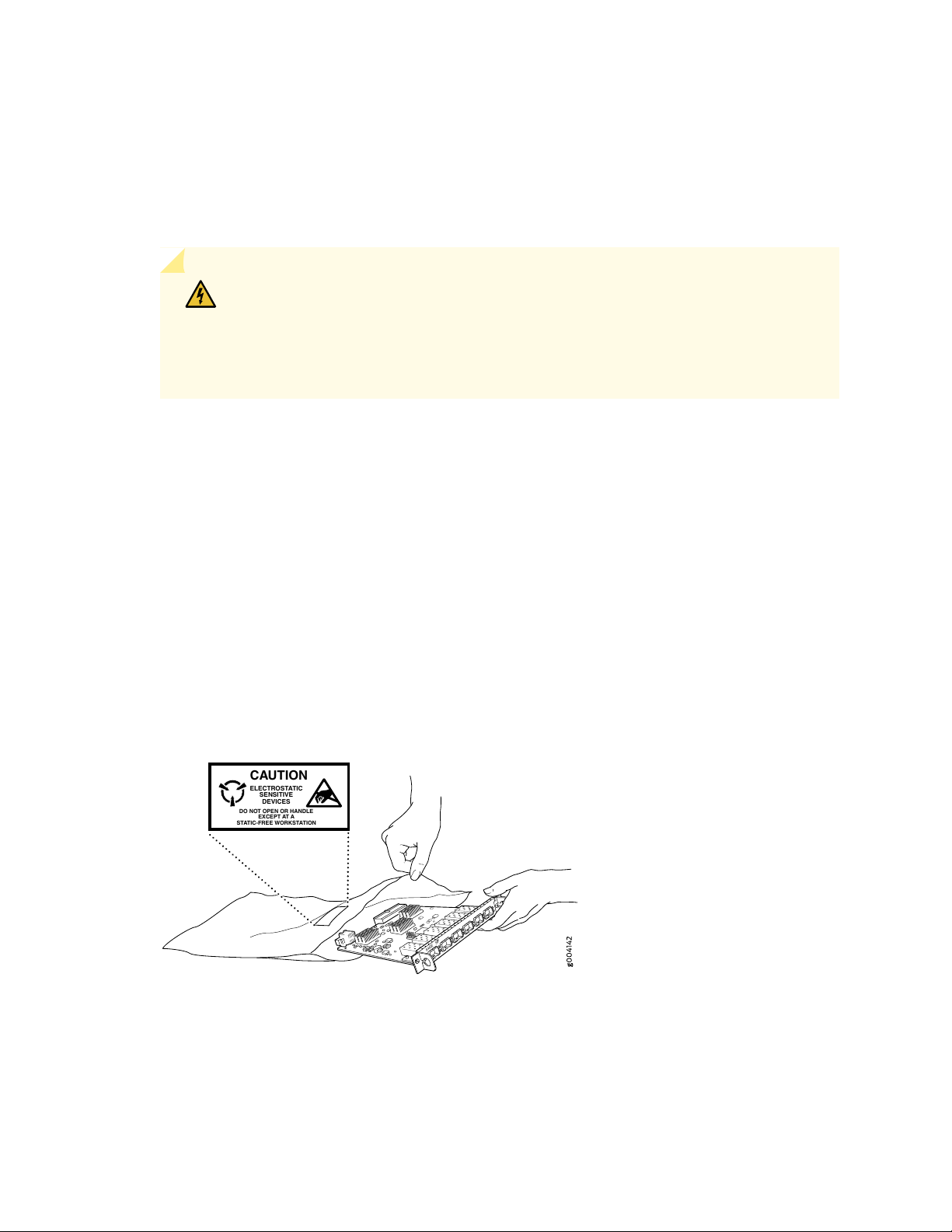
Always use an ESD wrist strap when you are handling components that are subject to ESD damage, and
6xGE SFP
0
1
2
3
4
5
CAUTION
ELECTROSTATIC
SENSITIVE
DEVICES
DO NOT OPEN OR HANDLE
EXCEPT AT A
STATIC-FREEWORKSTATION
•
make sure that it is in direct contact with your skin.
If a grounding strap is not available, hold the component in its antistatic bag (see Figure 25 on page 92)
in one hand and touch the exposed, bare metal of the device with the other hand immediately before
inserting the component into the device.
WARNING: For safety, periodically check the resistance value of the ESD grounding
strap. The measurement must be in the range 1 through 10 Mohms.
Avertissement Par mesure de sécurité, vérifiez régulièrement la résistance du bracelet
antistatique. Cette valeur doit être comprise entre 1 et 10 mégohms (Mohms).
When handling any component that is subject to ESD damage and that is removed from the device,
•
make sure the equipment end of your ESD wrist strap is attached to the ESD point on the chassis.
If no grounding strap is available, touch the exposed, bare metal of the device to ground yourself before
handling the component.
92
Avoid contact between the component that is subject to ESD damage and your clothing. ESD voltages
•
emitted from clothing can damage components.
When removing or installing a component that is subject to ESD damage, always place it component-side
•
up on an antistatic surface, in an antistatic card rack, or in an antistatic bag (see Figure 25 on page 92).
If you are returning a component, place it in an antistatic bag before packing it.
Figure 25: Placing a Component into an Antistatic Bag
Page 93

CAUTION: ANSI/TIA/EIA-568 cables such as Category 5e and Category 6 can get
electrostatically charged. To dissipate this charge, always ground the cables to a suitable
and safe earth ground before connecting them to the system.
Attention Les câbles ANSI/TIA/EIA-568, par exemple Cat 5e et Cat 6, peuvent
emmagasiner des charges électrostatiques. Pour évacuer ces charges, reliez toujours
les câbles à une prise de terre adaptée avant de les raccorder au système.
Fire Safety Requirements
In the event of a fire emergency, the safety of people is the primary concern. You should establish
procedures for protecting people in the event of a fire emergency, provide safety training, and properly
provision fire-control equipment and fire extinguishers.
93
In addition, you should establish procedures to protect your equipment in the event of a fire emergency.
Juniper Networks products should be installed in an environment suitable for electronic equipment. We
recommend that fire suppression equipment be available in the event of a fire in the vicinity of the
equipment and that all local fire, safety, and electrical codes and ordinances be observed when you install
and operate your equipment.
Fire Suppression
In the event of an electrical hazard or an electrical fire, you should first turn power off to the equipment
at the source. Then use a Type C fire extinguisher, which uses noncorrosive fire retardants, to extinguish
the fire.
Fire Suppression Equipment
Type C fire extinguishers, which use noncorrosive fire retardants such as carbon dioxide and Halotron™,
are most effective for suppressing electrical fires. Type C fire extinguishers displace oxygen from the point
of combustion to eliminate the fire. For extinguishing fire on or around equipment that draws air from the
environment for cooling, you should use this type of inert oxygen displacement extinguisher instead of an
extinguisher that leaves residues on equipment.
Page 94
Do not use multipurpose Type ABC chemical fire extinguishers (dry chemical fire extinguishers). The
primary ingredient in these fire extinguishers is monoammonium phosphate, which is very sticky and
difficult to clean. In addition, in the presence of minute amounts of moisture, monoammonium phosphate
can become highly corrosive and corrodes most metals.
Any equipment in a room in which a chemical fire extinguisher has been discharged is subject to premature
failure and unreliable operation. The equipment is considered to be irreparably damaged.
NOTE: To keep warranties effective, do not use a dry chemical fire extinguisher to control a fire
at or near a Juniper Networks device. If a dry chemical fire extinguisher is used, the unit is no
longer eligible for coverage under a service agreement.
We recommend that you dispose of any irreparably damaged equipment in an environmentally responsible
manner.
94
Laser and LED Safety Guidelines and Warnings
IN THIS SECTION
General Laser Safety Guidelines | 95
Class 1 Laser Product Warning | 96
Class 1 LED Product Warning | 97
Laser Beam Warning | 98
Juniper Networks devices are equipped with laser transmitters, which are considered a Class 1 Laser
Product by the U.S. Food and Drug Administration and are evaluated as a Class 1 Laser Product per EN
60825-1 requirements.
Observe the following guidelines and warnings:
Page 95

General Laser Safety Guidelines
When working around ports that support optical transceivers, observe the following safety guidelines to
prevent eye injury:
Do not look into unterminated ports or at fibers that connect to unknown sources.
•
Do not examine unterminated optical ports with optical instruments.
•
Avoid direct exposure to the beam.
•
WARNING: Unterminated optical connectors can emit invisible laser radiation. The
lens in the human eye focuses all the laser power on the retina, so focusing the eye
directly on a laser source—even a low-power laser—could permanently damage the
eye.
Avertissement Les connecteurs à fibre optique sans terminaison peuvent émettre
un rayonnement laser invisible. Le cristallin de l’œil humain faisant converger toute
la puissance du laser sur la rétine, toute focalisation directe de l’œil sur une source
laser, —même de faible puissance—, peut entraîner des lésions oculaires irréversibles.
95
Page 96

Class 1 Laser Product Warning
WARNING: Class 1 laser product.
Waarschuwing Klasse-1 laser produkt.
Varoitus Luokan 1 lasertuote.
Avertissement Produit laser de classe I.
Warnung Laserprodukt der Klasse 1.
Avvertenza Prodotto laser di Classe 1.
Advarsel Laserprodukt av klasse 1.
Aviso Produto laser de classe 1.
¡Atención! Producto láser Clase I.
96
Varning! Laserprodukt av klass 1.
Page 97

Class 1 LED Product Warning
WARNING: Class 1 LED product.
Waarschuwing Klasse 1 LED-product.
Varoitus Luokan 1 valodiodituote.
Avertissement Alarme de produit LED Class I.
Warnung Class 1 LED-Produktwarnung.
Avvertenza Avvertenza prodotto LED di Classe 1.
Advarsel LED-produkt i klasse 1.
Aviso Produto de classe 1 com LED.
¡Atención! Aviso sobre producto LED de Clase 1.
97
Varning! Lysdiodprodukt av klass 1.
Page 98

Laser Beam Warning
WARNING: Do not stare into the laser beam or view it directly with optical instruments.
Waarschuwing Niet in de straal staren of hem rechtstreeks bekijken met optische
instrumenten.
Varoitus Älä katso säteeseen äläkä tarkastele sitä suoraan optisen laitteen avulla.
Avertissement Ne pas fixer le faisceau des yeux, ni l'observer directement à l'aide
d'instruments optiques.
Warnung Nicht direkt in den Strahl blicken und ihn nicht direkt mit optischen Geräten
prüfen.
Avvertenza Non fissare il raggio con gli occhi né usare strumenti ottici per osservarlo
direttamente.
98
Advarsel Stirr eller se ikke direkte p strlen med optiske instrumenter.
Aviso Não olhe fixamente para o raio, nem olhe para ele directamente com instrumentos
ópticos.
¡Atención! No mirar fijamente el haz ni observarlo directamente con instrumentos
ópticos.
Varning! Rikta inte blicken in mot strålen och titta inte direkt på den genom optiska
instrument.
Page 99

Radiation from Open Port Apertures Warning
WARNING: Because invisible radiation might be emitted from the aperture of the
port when no fiber cable is connected, avoid exposure to radiation and do not stare
into open apertures.
Waarschuwing Aangezien onzichtbare straling vanuit de opening van de poort kan
komen als er geen fiberkabel aangesloten is, dient blootstelling aan straling en het
kijken in open openingen vermeden te worden.
Varoitus Koska portin aukosta voi emittoitua näkymätöntä säteilyä, kun kuitukaapelia
ei ole kytkettynä, vältä säteilylle altistumista äläkä katso avoimiin aukkoihin.
Avertissement Des radiations invisibles à l'il nu pouvant traverser l'ouverture du port
lorsqu'aucun câble en fibre optique n'y est connecté, il est recommandé de ne pas
regarder fixement l'intérieur de ces ouvertures.
99
Warnung Aus der Port-Öffnung können unsichtbare Strahlen emittieren, wenn kein
Glasfaserkabel angeschlossen ist. Vermeiden Sie es, sich den Strahlungen auszusetzen,
und starren Sie nicht in die Öffnungen!
Avvertenza Quando i cavi in fibra non sono inseriti, radiazioni invisibili possono essere
emesse attraverso l'apertura della porta. Evitate di esporvi alle radiazioni e non guardate
direttamente nelle aperture.
Advarsel Unngå utsettelse for stråling, og stirr ikke inn i åpninger som er åpne, fordi
usynlig stråling kan emiteres fra portens åpning når det ikke er tilkoblet en fiberkabel.
Aviso Dada a possibilidade de emissão de radiação invisível através do orifício da via
de acesso, quando esta não tiver nenhum cabo de fibra conectado, deverá evitar an
EXposição à radiação e não deverá olhar fixamente para orifícios que se encontrarem
a descoberto.
¡Atención! Debido a que la apertura del puerto puede emitir radiación invisible cuando
no existe un cable de fibra conectado, evite mirar directamente a las aperturas para
no exponerse a la radiación.
Varning! Osynlig strålning kan avges från en portöppning utan ansluten fiberkabel och
du bör därför undvika att bli utsatt för strålning genom att inte stirra in i oskyddade
öppningar.
Page 100
Maintenance and Operational Safety Guidelines and Warnings
IN THIS SECTION
Battery Handling Warning | 101
Jewelry Removal Warning | 102
Lightning Activity Warning | 104
Operating Temperature Warning | 105
Product Disposal Warning | 107
100
While performing the maintenance activities for devices, observe the following guidelines and warnings:
 Loading...