


Security Products
1-888-314-JTAC
(1-888-314-5822 - toll free in U.S., Canada, and Mexico)
or go to the link to request service
http://www.juniper.net/support/requesting-support.html
Secure Services Gateway (SSG) 20
Hardware Installation and Configuration Guide- Beta3
ScreenOS Version 5.4.0
Juniper Networks, Inc.
1194 North Mathilda Avenue
Sunnyvale, CA 94089
USA
408-745-2000
www.juniper.net
Part Number: 530-015646-01, Revision Beta3

Copyright Notice
The following information is for FCC compliance of Class B devices: The equipment described in this manual generates and may radiate
radio-frequency energy. If it is not installed in accordance with Juniper Network’s installation instructions, it may cause interference with
radio and television reception.
This equipment has been tested and found to comply with the limits for a Class B digital device in accordance with the specifications in
part 15 of the FCC rules. These specifications are designed to provide reasonable protection against such interference in a residential
installation. However, there is no guarantee that interference will not occur in a particular installation.
If this equipment does cause harmful interference to radio or television reception, which can be determined by turning the equipment off
and on, the user is encouraged to try to correct the interference by one or more of the following measures:
Reorient or relocate the receiving antenna.
Increase the separation between the equipment and receiver.
Consult the dealer or an experienced radio/TV technician for help.
Connect the equipment to an outlet on a circuit different from that to which the receiver is connected.
Caution:
- Changes or modifications to this product could void the user's warranty and authority to operate this device.
- To comply with FCC RF exposure compliance requirements, a separation distance of at least 20 cm must be maintained between the
antenna of this device and all persons.
- This Transmitter must not be co-located or operating in conjunction with any other antenna or transmitter
Disclaimer
THE SOFTWARE LICENSE AND LIMITED WARRANTY FOR THE ACCOMPANYING PRODUCT ARE SET FORTH IN THE
INFORMATION PACKET THAT SHIPPED
WITH THE PRODUCT AND ARE INCORPORATED HEREIN BY THIS REFERENCE. IF YOU ARE UNABLE TO LOCATE THE
SOFTWARE LICENSE OR LIMITED
WARRANTY, CONTACT YOUR JUNIPER NETWORKS REPRESENTATIVE FOR A COPY.
Writer: Carrie Nowocin
Editor: Lisa Eldridge
DGT Warning:
依據 低功率電波輻射性電機管理辦法
第十二條 經型式認證合格之低功率射頻電機,非經許可,公司、商號或使用者均不得擅自變更頻率、加大功率或變更原設
計之特性及功能。
第十四條 低功率射頻電機之使用不得影響飛航安全及干擾合法通信;經發現有干擾現象時,應立即停用,並改善至無干
擾時方得繼續使用。
前項合法通信,指依電信規定作業之無線電信。低功率射頻電機須忍受合法通信或工業、科學及醫療用電波輻射性電機設備之干擾。
1.本機限在不干擾合法電台與不受被干擾保障條件下於室內使用
2.為減少電磁波干擾, 請妥適使用
Copyright © 2006 Juniper Networks, Inc. All rights reserved.
Juniper Networks and the Juniper Networks logo are registered trademarks of Juniper Networks, Inc. in the United States and other countries. All other
trademarks, service marks, registered trademarks, or registered service marks in this document are the property of Juniper Networks or their respective
owners. All specifications are subject to change without notice. Juniper Networks assumes no responsibility for any inaccuracies in this document or for
any obligation to update information in this document. Juniper Networks reserves the right to change, modify, transfer, or otherwise revise this publication
without notice.
FCC Statement
The following information is for FCC compliance of Class B devices: The equipment described in this manual generates and may radiate radio-frequency
energy. If it is not installed in accordance with Juniper Network’s installation instructions, it may cause interference with radio and television reception.
This equipment has been tested and found to comply with the limits for a Class B digital device in accordance with the specifications in part 15 of the FCC
rules. These specifications are designed to provide reasonable protection against such interference in a residential installation. However, there is no
guarantee that interference will not occur in a particular installation.
If this equipment does cause harmful interference to radio or television reception, which can be determined by turning the equipment off and on, the user
is encouraged to try to correct the interference by one or more of the following measures:
Reorient or relocate the receiving antenna.
Increase the separation between the equipment and receiver.
Consult the dealer or an experienced radio/TV technician for help.
Connect the equipment to an outlet on a circuit different from that to which the receiver is connected.
Caution: Changes or modifications to this product could void the user's warranty and authority to operate this device.
Disclaimer
THE SOFTWARE LICENSE AND LIMITED WARRANTY FOR THE ACCOMPANYING PRODUCT ARE SET FORTH IN THE INFORMATION PACKET THAT SHIPPED
WITH THE PRODUCT AND ARE INCORPORATED HEREIN BY THIS REFERENCE. IF YOU ARE UNABLE TO LOCATE THE SOFTWARE LICENSE OR LIMITED
WARRANTY, CONTACT YOUR JUNIPER NETWORKS REPRESENTATIVE FOR A COPY.
ii
Writer: Carrie Nowocin
Editor: Lisa Eldridge

Table of Contents
About This Guide vii
Organization .................................................................................................. vii
WebUI Conventions ...................................................................................... viii
CLI Conventions............................................................................................ viii
Obtaining Documentation and Technical Support........................................... ix
Chapter 1
Chapter 2
Hardware Overview 1
Port and Power Connectors .............................................................................2
Front Panel ...................................................................................................... 3
System Status LEDs ................................................................................... 3
Port Descriptions .......................................................................................5
Ethernet Ports ..................................................................................... 5
Console Port .......................................................................................5
AUX Port.............................................................................................5
Mini Physical Interface Module Port Descriptions ......................................6
Back Panel .......................................................................................................8
Power Adapter...........................................................................................8
Radio Transceiver......................................................................................8
Grounding Lug ........................................................................................... 8
Antennae Types......................................................................................... 9
Universal Serial Bus (USB) Host Module ..................................................... 9
Installing and Connecting the Device 11
Before You Begin ........................................................................................... 11
Equipment Rack Installation ..........................................................................12
Connecting the Interface Cable to a Device....................................................12
Connecting the Power....................................................................................13
Connect the Device to a Network................................................................... 13
Connect an SSG 20 Device to an Untrusted Network ............................... 13
Connecting Ethernet Ports ................................................................13
Connecting Serial (AUX/Console) Ports..............................................13
Connect an SSG Device to an Untrusted Network....................................14
Connect Mini PIMs to an Untrusted Network ....................................14
Connecting Other Mini PIMs .............................................................15
Connect the Device to an Internal Network or a Workstation ..................16
Connecting Ethernet Ports ................................................................16
Connecting the Wireless Antennae....................................................16
Chapter 3
Configure the Device 17
Access the Device ..........................................................................................18
Using a Console Connection .................................................................... 18
Using the WebUI .....................................................................................19
Table of Contents iii

SSG 20 Hardware Installation and Configuration Guide
Using Telnet ............................................................................................ 20
Default Device Settings ..................................................................................21
Basic Device Configuration ............................................................................ 23
Changing the Root Admin Name and Password ......................................23
Setting the Date and Time ....................................................................... 24
Bridge Group Interfaces ...........................................................................24
Administrative Access ............................................................................. 25
Management Services..............................................................................25
Host and Domain Name .......................................................................... 25
Default Route...........................................................................................26
Management Interface Address ...............................................................26
Backup Untrust Interface Configuration ................................................... 26
Wireless Configuration...................................................................................27
Wireless Network Configuration .............................................................. 28
Mini PIM Configuration ..................................................................................30
Asymmetrical DSL (ADSL) 2/2+ Interface ...............................................30
The ISDN Interface ..................................................................................34
The T1 Interface ......................................................................................35
The E1 Interface ...................................................................................... 36
The V.92 Modem Interface ......................................................................37
Basic Firewall Protections .............................................................................. 37
Verify External Connectivity ..........................................................................38
Reset the Device to Factory Defaults ..............................................................38
The Reset Pinhole.................................................................................... 38
Authentication and Encryption..........................................................30
Virtual Circuits to an ADSL2/2+ Interface......................................... 31
VPI/VCI and Multiplexing Method......................................................32
PPPoE or PPPoA ...............................................................................32
Static IP Address and Netmask.......................................................... 33
Chapter 4
Appendix A
Appendix A
Servicing the Device 41
Tools and Parts Required ...............................................................................41
Replacing a Physical Interface Module ...........................................................41
Removing a Blank Faceplate....................................................................42
Removing a Mini PIM ..............................................................................42
Installing a Mini PIM................................................................................43
Memory Upgrade ........................................................................................... 44
Specifications A-I
SSG 20 Physical Specifications ..........................................................................I
Electrical Specification ......................................................................................I
Environmental .................................................................................................II
Certifications....................................................................................................II
Safety ........................................................................................................II
EMC (Emissions)........................................................................................II
EMC Immunity ..........................................................................................II
European Telecommunications Standards Institute (ETSI) ........................III
T1 Interface ..............................................................................................III
Connectors......................................................................................................III
Initial Configuration Wizard A-I
Using the Initial Configuration Wizard ........................................................I
iv Table of Contents

Table of Contents
Index........................................................................................................................IX--1
Table of Contents
v

SSG 20 Hardware Installation and Configuration Guide
vi Table of Contents

About This Guide
The Juniper Networks Secure Services Gateway (SSG) 20 device is an integrated
router and firewall platform that provides Internet Protocol Security (IPSec) Virtual
Private Network (VPN) and firewall services for a branch office or a retail outlet.
Juniper Networks offers two models of the SSG 20 device:
SSG 20 Ethernet only
SSG 20-WLAN which has four integrated wireless interfaces.
Both of the SSG 20 devices support auxiliary (AUX), universal storage bus (USB)
storage, and two mini physical interface module (PIM) slots that can hold any of the
mini PIMs. The devices also provide protocol conversions between local area
networks (LANs) and wide area networks (WANs).
Organization
This document contains the following chapters:
Chapter 1, “Hardware Overview,” describes the chassis and components of an
SSG 20 device.
Chapter 2, “Installing and Connecting the Device,” describes how to install an SSG
20 device in a standard 19-inch equipment rack and how to connect cables and
power to the device.
Chapter 3, “Configure the Device,” describes how to configure and manage an
SSG 20 device and how to perform some basic configuration tasks.
Chapter 4, “Servicing the Device,” describes service and maintenance procedures
for an SSG 20 device.
Appendix A, “Specifications,” provides general system specifications for an SSG 20
device.
Appendix B, “Initial Configuration Wizard,” describes the Initial Configuration
Wizard steps.
Organization vii
SSG 20 Hardware Installation and Configuration Guide
WebUI Conventions
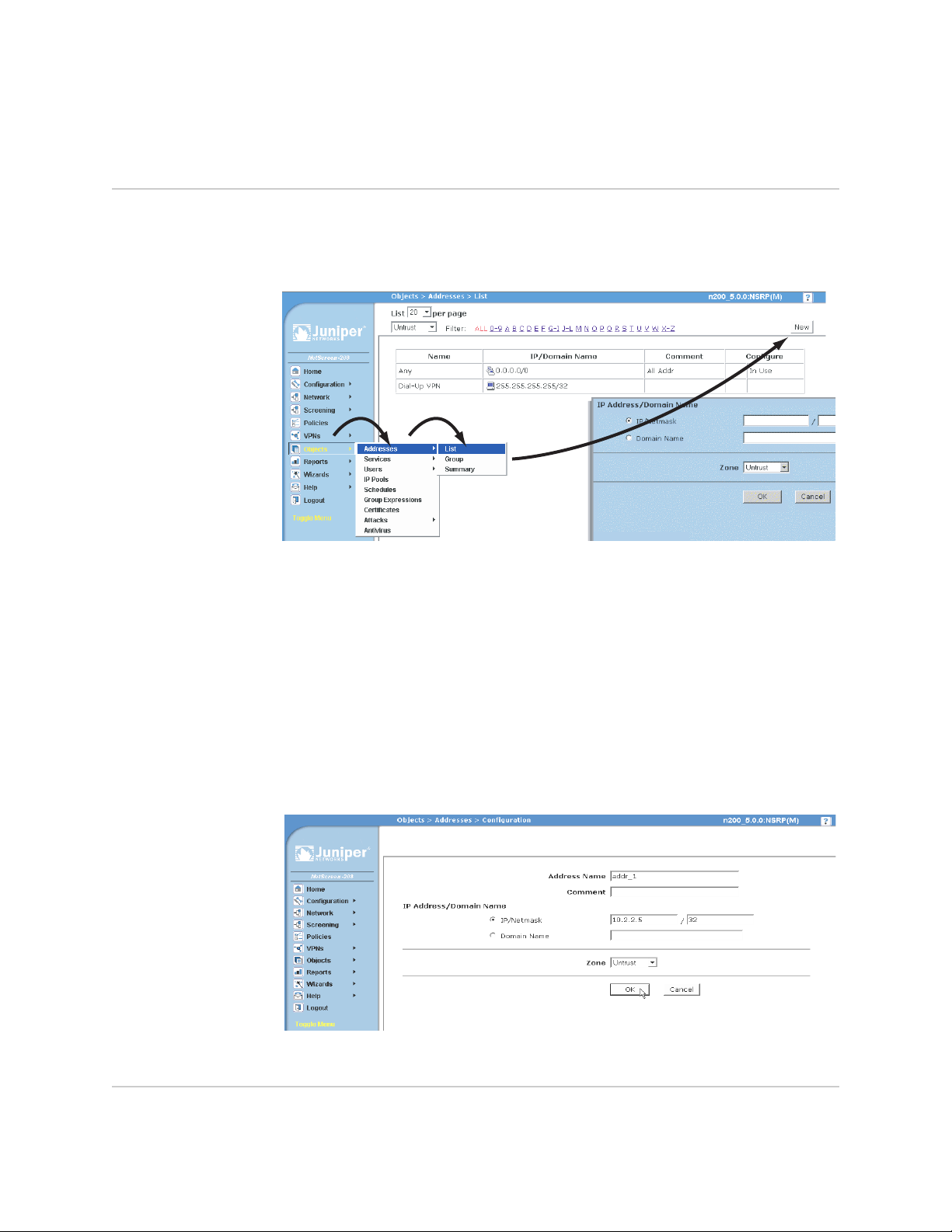
A chevron ( > ) shows the navigational sequence through the WebUI, which you
follow by clicking menu options and links. The following figure shows the following
path to the address configuration dialog box—Objects > Addresses > List > New:
Figure 1: WebUI Navigation
To perform a task with the WebUI, you first navigate to the appropriate dialog box,
where you then define objects and set parameters. The set of instructions for each
task is divided into navigational path and configuration settings:
The next figure lists the path to the address configuration dialog box with the
following sample configuration settings:
Objects > Addresses > List > New: Enter the following, then click OK:
Address Name: addr_1
IP Address/Domain Name:
IP/Netmask: (select), 10.2.2.5/32
Zone: Untrust
Figure 2: Navigational Path and Configuration Settings
CLI Conventions
viii WebUI Conventions
The following conventions are used to present the syntax of CLI commands in
examples and in text.

About This Guide
In examples:
Anything inside square brackets [ ] is optional.
Anything inside braces { } is required.
If there is more than one choice, each choice is separated by a pipe ( | ). For
example:
set interface { ethernet1 | ethernet2 | ethernet3 } manage
means “set the management options for the ethernet1, the ethernet2, or the
ethernet3 interface.”
Variables are in italic type:
set admin user name1 password xyz
In text:
Commands are in boldface type.
Variables are in italic type.
NOTE: When entering a keyword, you need to type only enough letters to identify the
word uniquely. For example, typing set adm u kath j12fmt54 is enough to enter
the command set admin user kathleen j12fmt54. Although you can use this
shortcut when entering commands, all the commands documented here are
presented in their entirety.
Obtaining Documentation and Technical Support
To obtain technical documentation for any Juniper Networks product, visit
www.juniper.net/techpubs/
For technical support, open a support case using the Case Manager link at
http://www.juniper.net/support/
1-408-745-9500 (outside the United States).
If you find any errors or omissions in this document, please contact us at the email
address below:
techpubs-comments@juniper.net
.
or call 1-888-314-JTAC (within the United States) or
Obtaining Documentation and Technical Support ix

SSG 20 Hardware Installation and Configuration Guide
x Obtaining Documentation and Technical Support

Chapter 1
Hardware Overview
This chapter provides detailed descriptions of the SSG 20 chassis and components.
It contains the following sections:
“Port and Power Connectors” on this page
“Front Panel” on page 3
“Back Panel” on page 8
1
SSG 20 Hardware Installation and Configuration Guide
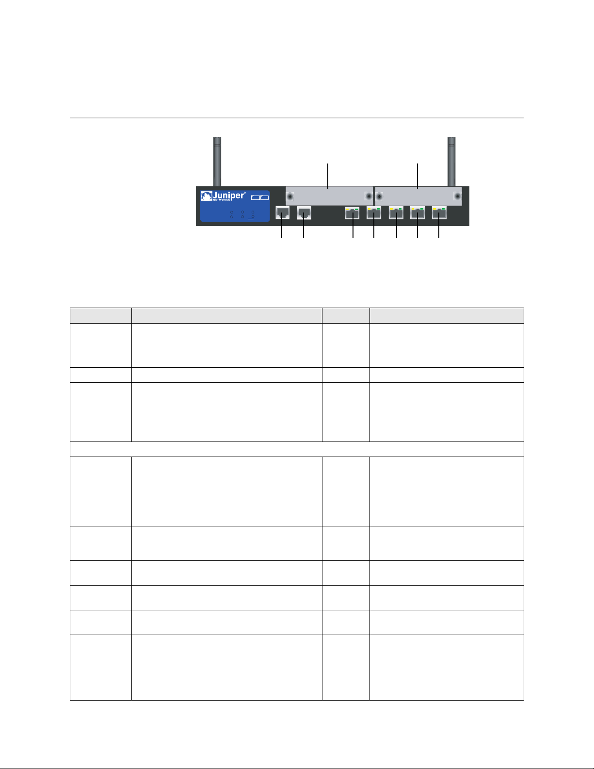
Port and Power Connectors
Antenna AAntenna B
PIM 2PIM 1
SSG 20
POWER
STATUS
12
802.11a
PIM 1
PIM 2
b/g
WLAN
AUX
AUX
LINK
10/100
10/100
10/100
10/100
0/0
0/0
0/0
10/100
0/0
0/0
AUX Console e0/0 e0/1 e0/2 e0/3 e0/4
Table 1 shows the ports and power connectors on an SSG 20 device.
Table 1: SSG 20 Port and Power Connectors
Port Description Connector Speed/Protocol
Ports 0/0-0/4 Enables direct connections to workstations or a LAN
connection through a switch or hub. This
connection also allows you to manage the device
through a Telnet session or the WebUI.
USB Enables a 1.1 USB connection with the system. N/A 12M (full speed) or 1.5M (low speed)
Console Enables a serial connection with the system. Used
for terminal-emulation connectivity to launch
Command Line Interface (CLI) sessions.
AUX Enables a backup serial Internet connection through
an external modem.
Mini PIM
ADSL 2/2+ Enables an Internet connection through an ADSL
data link.
V.92 Modem Enables a primary or backup Internet or untrusted
network connection to an Internet Service Provider
(ISP).
T1 Enables a connection to the T1 line to the untrusted
network.
E1 Enables a connection to the E1 line to the untrusted
network.
ISDN Enables the ISDN line to be used as the untrust or
backup interface.
Antenna A & B
(SSG 20-WLAN)
Enables a direct connection to workstations in the
vicinity of a wireless radio connection.
RJ-45 10/100 Mbps Ethernet
Autosensing duplex and auto MDI/MDIX
RJ-45 9600 bps/ RS-232C serial
RJ-45 9600 bps — 115 Kbps/ RS-232C serial
RJ-11
(Annex A)
RJ-45
(Annex B)
ANSI T1.413 Issue 2 (Annex A only)
ITU G.992.1 (G.dmt)
ITU G.992.2 (G.lite) (Annex A only)
ITU G.992.3 (ADSL2)
ITU G.992.5 (ADSL2+)
RJ-11 9600 bps — 115 Kbps/ RS-232 Serial
autosensing duplex and polarity
RJ-45
RJ-45
RJ-45 B-channels at 64 Kbps
RPSMA 802.11a (54 Mbps on 5GHz radio band)
802.11b (11 Mbps on 2.4GHz radio band)
802.11g (54 Mbps on 2.4GHz radio band)
802.11 superG (108 Mbps on 2.4GHz
radio band)
2 Port and Power Connectors
Front Panel
System Status LEDs
This section describes the following elements on the front panel of an SSG 20
device:
System Status LEDs
Port Descriptions
Mini Physical Interface Module Port Descriptions
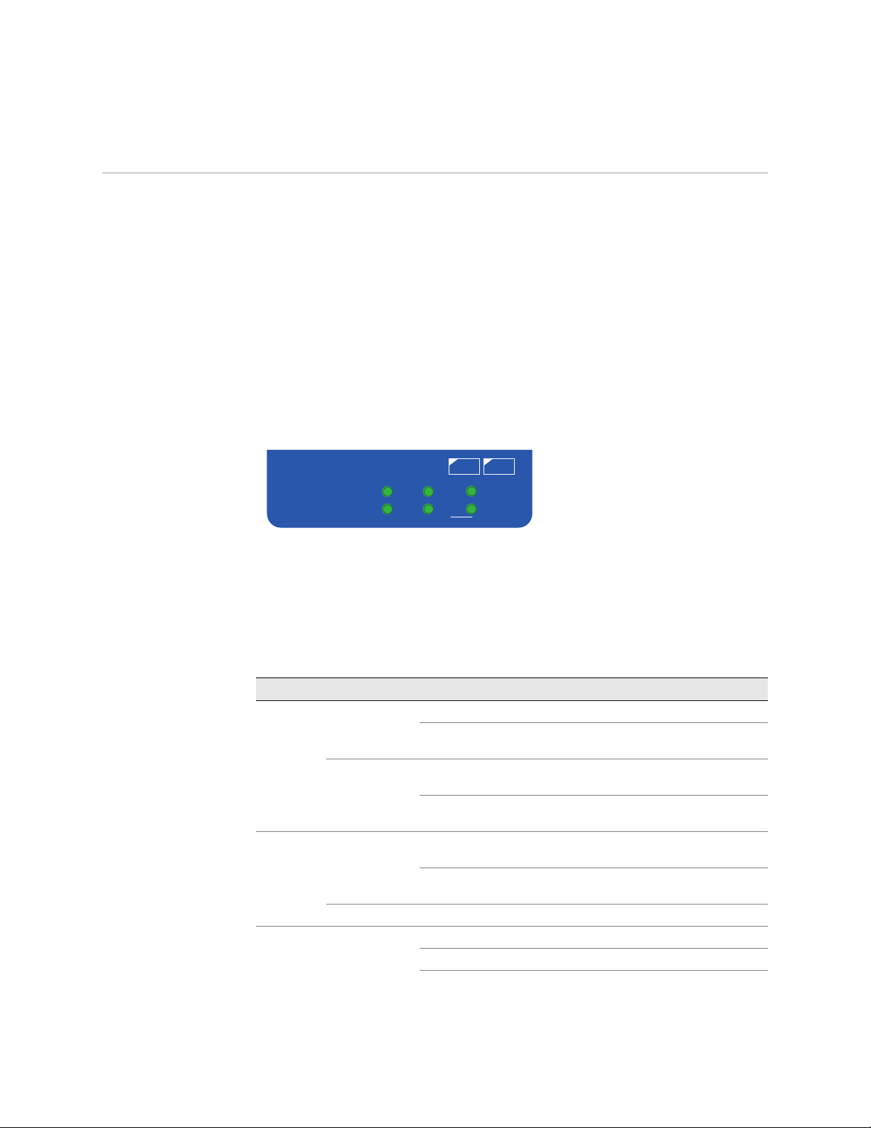
The system status LEDs display information about critical device functions. Figure 1
illustrates the position of each status LED on the system dashboard. The WLAN
LEDs are only present on the SSG 20-WLAN device.
Figure 1: Status LED
12
POWER
STATUS
PIM 1
PIM 2
802.11a
b/g
WLAN
When the system powers up, the POWER LED changes from off to blinking green
and the STATUS LED changes in the following sequence: red, green, blinking green.
Startup takes approximately 2 minutes to complete. If you want to turn the system
off and on again, we recommend waiting a few seconds between shutting it down
and powering it back up. Table 2 provides the name, color, status, and description of
each system status LED.
Table 2: LED Descriptions
Name Color Status Description
POWER Green On steadily Indicates that the system is receiving power
Off Indicates that the system is not receiving
power
Red On steadily Indicates that the device is not operating
normally
Off Indicates that the device is operating
normally
STATUS Green On steadily Indicates that the system is booting up or
performing diagnostics
Blinking Indicates that the device is operating
normally
Red Blinking Indicates that there was an error detected
PIM 1 Green On steadily Indicates that the mini PIM is functioning
Blinking Indicates that the mini PIM is passing traffic
Off Indicates that the mini PIM not operational
Front Panel 3

SSG 20 Hardware Installation and Configuration Guide
Name Color Status Description
PIM 2 Green On steadily Indicates that the mini PIM is functioning
WLAN
802.11a Green On steadily Indicates that a wireless connection is
b/g Green On steadily Indicates that a wireless connection is
Blinking Indicates that the mini PIM is passing traffic
Off Indicates that the mini PIM not operational
established but there is no link activity
Blinking slowly Indicates that a wireless connection is
established. The baud rate is proportional to
the link activity
Off Indicates that there is no wireless connection
established
established but there is no link activity
Blinking slowly Indicates that a wireless connection is
established. The baud rate is proportional to
the link activity
Off Indicates that there is no wireless connection
established
4 Front Panel

Port Descriptions
This section explains the purpose and function of the following:
Ethernet Ports on page 5
Console Port on page 5
AUX Port on page 5
Ethernet Ports
Five 10/100 Ethernet ports provide LAN connections to hubs, switches, local servers,
and workstations. You can also designate an Ethernet port for management traffic.
The ports are labeled 0/0 through 0/4. For the default zone bindings for each
Ethernet port, see “Default Device Settings” on page 21.
When configuring one of the ports, reference the interface name that corresponds
to the location of the port. From left to right on the front panel, the interface names
for the ports are named ethernet0/0 through ethernet0/4.
Figure 2 displays the location of the LEDs on each Ethernet port.
Figure 2: Activity Link LEDs
TX/RX
LINK
Table 3 describes the Ethernet port LEDs.
Table 3: LAN Port LEDs
Name Color Status Description
LINK Green On steadily
Off
TX/RX Green Blinking
Off
Port is online
Port is offline
Traffic is passing through. The baud rate is
proportional to the link activity.
Port might be on but is not receiving data
Console Port
The Console port is an RJ-45 serial port wired as DCE that can used for local
administration. An RJ-45 to DB-9 adapter is supplied.
See “Connectors” on page III for the RJ-45 connector pinouts.
AUX Port
The auxiliary (AUX) port is an RJ-45 serial port wired as a DTE that you can connect
to a modem to allow remote administration. We do not recommend using this port
for regular remote administration. The AUX port is typically assigned to be the
backup serial interface. The baud rate is adjustable from 9600 bps to 115200 bps
and requires hardware flow control.
Front Panel 5
SSG 20 Hardware Installation and Configuration Guide
See “Connectors” on page III for the RJ-45 connector pinouts.
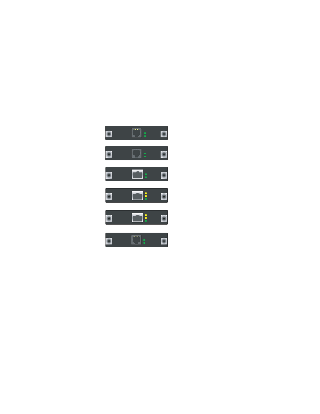
Mini Physical Interface Module Port Descriptions
Each mini physical interface module (PIM) supported on a device has the following
components:
One cable connector port—Accepts a network media connector. Figure 3 shows
the available mini PIMs. You can install up to two mini PIMs in a device.
Figure 3: Mini PIMs on the SSG 20
ADSL 2/2+
ADSL 2/2+
ISDN (BRI )
T1
E1
V.92
SYNC
TX/RX
SYNC
TX/RX
Channel B1
Channel B2
ALARM
LOOP BACK
CD
ALARM
LOOP BACK
CD
TX/RX
CD
ADSL2/2+ Annex B
ADSL2/2+ Annex A
ISDN BRI
T1
E1
V.92
Two to three status LEDs—Indicates port status. Table 4 describes the meaning
of the LED states.
6 Front Panel

Table 4: Mini PIM LED States on the SSG 20
Type Name Color State Description
ADSL 2/2+
(Annex A
and B)
ISDN (BRI) CH B1 Green On steadily Indicates that B-Channel 1 is active
T1/E1 ALARM Yellow On steadily Indicates that there is a local or remote
V.92 CD Green On steadily Indicates that the link is active
SYNC Green On steadily Indicates that the ADSL interface is trained
Blinking Indicates training is in progress
Off Interface is idle
TX/RX Green Blinking Indicates that traffic is passing through
Off Indicates that no traffic passing through
Off Indicates that B-Channel 1 is not active
CH B2 Green On steadily Indicates that B-Channel 2 is active
Off Indicates that B-Channel 2 is not active
alarm; device has detected a failure
Off Indicates that there are no alarms or failures
LOOP BACK Yellow On steadily Indicates that a loopback or line state is
detected
Off Indicates that the loopback is not active
CARRIER
DETECT
TX/RX Green Blinking Indicates that traffic is passing through
Green On steadily Indicates a carrier was detected and the
internal DSU/CSU in the mini PIM is
communicating with another DSU/CSU
Off Indicates that carrier detect is not active
Off Indicates that the serial interface is not in
service
Off Indicates that no traffic is passing through
NOTE: Mini PIMs are not hot-swappable. They must be installed in the front panel slots
before the system is booted up.
Front Panel 7

SSG 20 Hardware Installation and Configuration Guide
Back Panel
This section describes the back panel of an SSG 20 device:
“Power Adapter” on this page
“Radio Transceiver,” on this page
“Grounding Lug,” on this page
“Antennae Types” on page 9
“Universal Serial Bus (USB) Host Module” on page 9
Figure 4: Back Panel of an SSG Device
Power Adapter
Radio Transceiver
Antenna A Antenna B
grounding lug
USB host module
Power
adapter
The POWER LED on the front panel of a device either glows green or is off. Green
indicates correct function, and off indicates power adapter failure.
The SSG 20-WLAN contains two wireless connectivity radio transceivers, which
support 802.11a/b/g standards. The first transceiver (WLAN 0) uses the 2.4 GHz
radio band, which supports the 802.11b standard at 11 Mbps, the 802.11g standard
at 54 Mbps, and 802.11 SuperG standard at 108 Mbps. The second radio transceiver
(WLAN 1) uses the 5 GHz radio band, which supports the 802.11a standard at 54
Mbps. The two radio transceivers can work simultaneously, For information on
configuring the wireless radio band, see “Wireless Network Configuration” on
page 28.
Grounding Lug
8 Back Panel
A one-hole grounding lug is provided on the back of the chassis to connect the
device to earth ground (see Figure 4).
To ground the device before connecting power, you connect a grounding cable to
earth ground and then attach the cable to the lug on the rear of the chassis.

Antennae Types
The SSG 20-WLAN device supports three types of custom-built radio antennae:
Diversity antennae — The diversity antennae provide 2dBi omnidirectional
coverage and a fairly uniform level of signal strength within the area of
coverage and are suitable for most installations. this type of antennae are
shipped with the device.
External omnidirectional antenna — The external antenna provides 2dBi
omnidirectional coverage. Unlike diversity antennae, which function as a pair,
an external antenna operates to eliminate an echo effect that can sometimes
occur from slightly delayed characteristics in signal reception when two are in
use.
External directional antenna — The external directional antenna provides
2dBi unidirectional coverage and is well suited for such places as hallways and
outer walls (with the antenna facing inward).
Universal Serial Bus (USB) Host Module
The slot labeled USB on the back panel of an SSG 20 device implements a host-only
USB 1.1 host module for a USB device adapter or USB flash key, as defined in the
CompactFlash Specification published by the CompactFlash Association. When the
USB storage device is installed and configured, it automatically acts as a secondary
storage device.
The USB host module allows file transfers, such as device configurations, user
certifications, and update version images between an external USB flash key and
the internal flash storage located in the security device. The USB host module
supports USB 2.0 specification at either low-speed (1.5M) or full-speed (12M) file
transfer.
To use a USB flash key to transfer files between the device, perform the following
steps:
1. Insert the USB flash key into the USB host module on the security device.
2. Save the files from the USB flash key to the internal flash storage on the device
with the save { software | config | image-key } from usb filename to flash CLI
command.
3. Before removing the USB flash key, stop the host module with the exec
usb-device stop CLI command.
4. It is now safe to remove the USB flash key.
If you want to delete a file from the USB flash key, use the delete file usb:/filename
CLI command.
If you want to view the saved file information on the USB flash key or internal flash
storage, use the get file info CLI command.
Back Panel 9

SSG 20 Hardware Installation and Configuration Guide
10 Back Panel

Chapter 2
Installing and Connecting the Device
This chapter describes how to install an SSG 20 device in a standard 19-inch
equipment rack and connect cables and power to the device. Topics in this chapter
include:
“Before You Begin” on this page
“Equipment Rack Installation” on page 12
“Connecting the Interface Cable to a Device” on page 12
“Connecting the Power” on page 13
“Connect the Device to a Network” on page 13
NOTE: For safety warnings and instructions, please refer to the Juniper Networks Security
Products Safety Guide. Before working on any equipment, you should be aware of
the hazards involved with electrical circuitry and be familiar with standard
practices for preventing accidents.
Before You Begin
The location of the chassis, the layout of the equipment rack, and the security of
your wiring room are crucial for proper system operation.
WARNING: To prevent abuse and intrusion by unauthorized personnel, install an
SSG 20 device in a secure environment.
Observing the following precautions can prevent shutdowns, equipment failures,
and injuries:
Before installation, always check that the power supply is disconnected from
any power source.
Ensure that the room in which you operate the device has adequate air
circulation and that the room temperature does not exceed 104× F (40× C).
Before You Begin 11

SSG 20 Hardware Installation and Configuration Guide
Do not place the device in an equipment rack frame that blocks an intake or
exhaust port. Ensure that enclosed racks have fans and louvered sides.
Correct these hazardous conditions before any installation: moist or wet floors,
leaks, ungrounded or frayed power cables, or missing safety grounds.
Equipment Rack Installation
You can front-mount an SSG 20 device into a standard 19-inch equipment rack. The
device is shipped with mounting brackets installed.
To front-mount an SSG 20 device, you need a number 2 phillips screwdriver (not
provided) and four screws that are compatible with the equipment rack (not
provided).
To install an SSG 20 device onto a rack:
1. Align the rack mount ears to the device.
2. Place the screws in the holes and use a phillips screwdriver to secure them.
3. Mount the device on the rack with the provided screws.
4. Plug the power supply into the power outlet.
Connecting the Interface Cable to a Device
To connect the interface cable to a device, perform the following steps:
1. Have ready a length of the type of cable used by the interface.
2. Insert the cable connector into the cable-connector port on the interface
faceplate.
3. Arrange the cable as follows to prevent it from dislodging or developing stress
points:
a. Secure the cable so that it is not supporting its own weight as it hangs to
the floor.
b. Place any excess cable out of the way in a neatly coiled loop.
12 Equipment Rack Installation
c. Use fasteners to maintain the shape of the cable loops.

Connecting the Power
To connect the power to a device, perform the following steps:
1. Plug the DC connector end of the power cable into the DC power receptacle on
the back of the SSG device.
2. Plug the AC adapter end of the power cable into an AC power source.
WARNING: We recommend using a surge protector for the power connection.
Connect the Device to a Network
An SSG 20 device provides firewall and general security for networks when it is
placed between internal networks and the untrusted network. This section
describes the following:
Connecting the device to an untrusted network
Connecting the device mini PIMs to an untrusted Network
Connecting the device to an internal network or workstation
Connect an SSG 20 Device to an Untrusted Network
You can connect your SSG 20 device to the untrusted network in one of the
following ways:
Connecting Ethernet Ports
Connecting Serial (AUX/Console) Ports
Connecting Ethernet Ports
To establish a high-speed connection, connect the provided Ethernet cable from the
Ethernet port marked 0/0 on an SSG 20 device to the external router. This Ethernet
port (0/0) is assigned to the ethernet0/0 interface, which is by default bound to the
Untrust security zone. The device autosenses the correct speed, duplex, and
MDI/MDIX settings.
Connecting Serial (AUX/Console) Ports
You can connect to the untrusted network with an RJ-45 straight through serial
cable and external modem.
WARNING: Make sure that you do not inadvertently connect the Console, AUX, or
Ethernet ports on the device to the telephone outlet.
Connecting the Power 13
SSG 20 Hardware Installation and Configuration Guide
Connect an SSG Device to an Untrusted Network
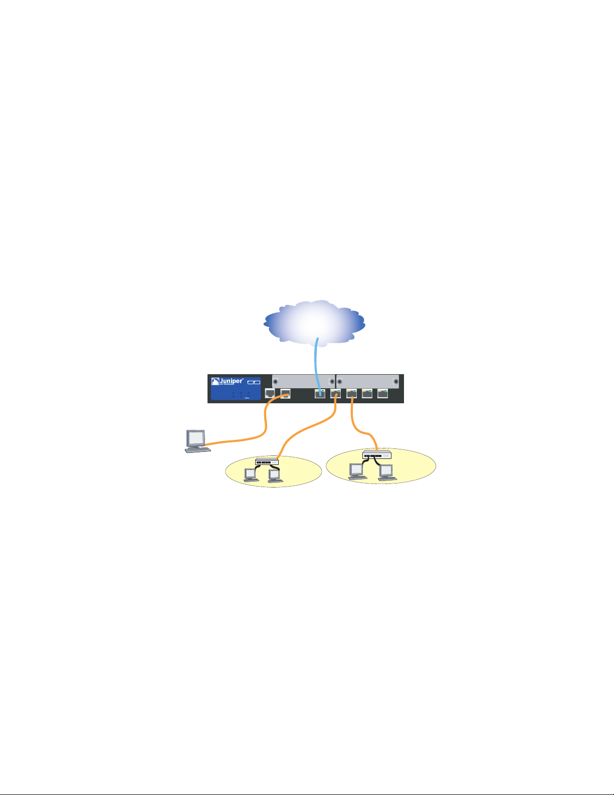
Figure 5 shows basic network cabling connections for a device. This figure shows
two blank PIMs and the 10/100 Ethernet ports are cabled as follows:
The port labeled 0/0 (ethernet0/0 interface) is connected to the untrust
network.
The port labeled 0/1 (ethernet0/1 interface) is connected to a switch that
connects workstations on the DMZ LAN.
The ports labeled 0/2 through 0/4 (ethernet0/2 through ethernet0/4 interfaces)
are connected to a switch that connects workstations to the trusted network.
The console port is connected to a serial terminal for management access.
Figure 5: Basic Networking Example
Internet
untrust interface
SSG 20
12
802.11a
POWER
PIM 1
PIM 2
b/g
STATUS
WLAN
AUX
AUX
LINK
10/100
10/100
10/100
10/100
0/0
0/0
0/0
10/100
0/0
0/0
bgroup0interface (ethernet0/2 —ethernet0/4)
console
DMZ Zone
Trust Zone
Connect Mini PIMs to an Untrusted Network
This section explains how to connect the device mini PIMs to an untrusted network.
Connecting the ADSL2/2+ Mini PIM
Connect the provided ADSL cable from the ADSL2/2+ mini PIM to your telephone
outlet. The ADSL port on the Annex A version of the device uses an RJ-11 connector,
while the Annex B version uses an RJ-45 connector. In the case of Annex B models,
the cable you connect from the ADSL port to the telephone outlet is identical in
appearance and wiring to a straight through 10 Base-T Ethernet cable.
14 Connect the Device to a Network
Connecting Splitters and Microfilters
A signal splitter divides the telephone signal into low-frequency voice signals for
voice calls and high-frequency data signals for data traffic. Your service provider
usually installs the splitter as part of the equipment that connects your site
telephone lines to the provider network.
There are also splitters that you may be able to install yourself, depending upon
your service-provider equipment. If you are installing such a splitter yourself,
connect the ADSL cable from the device and the telephone line to the appropriate
connectors (for example, “data” or “voice”) on the splitter. You connect the other
end of the splitter to the telephone outlet.
You may need to install a microfilter on each telephone, fax machine, answering
machine, or analog modem that connects to the ADSL line. The microfilter filters
out high-frequency noise on the telephone line. You install the microfilter on the
telephone line between the telephone, fax machine, answering machine, or analog
modem and the voice connector on the splitter.
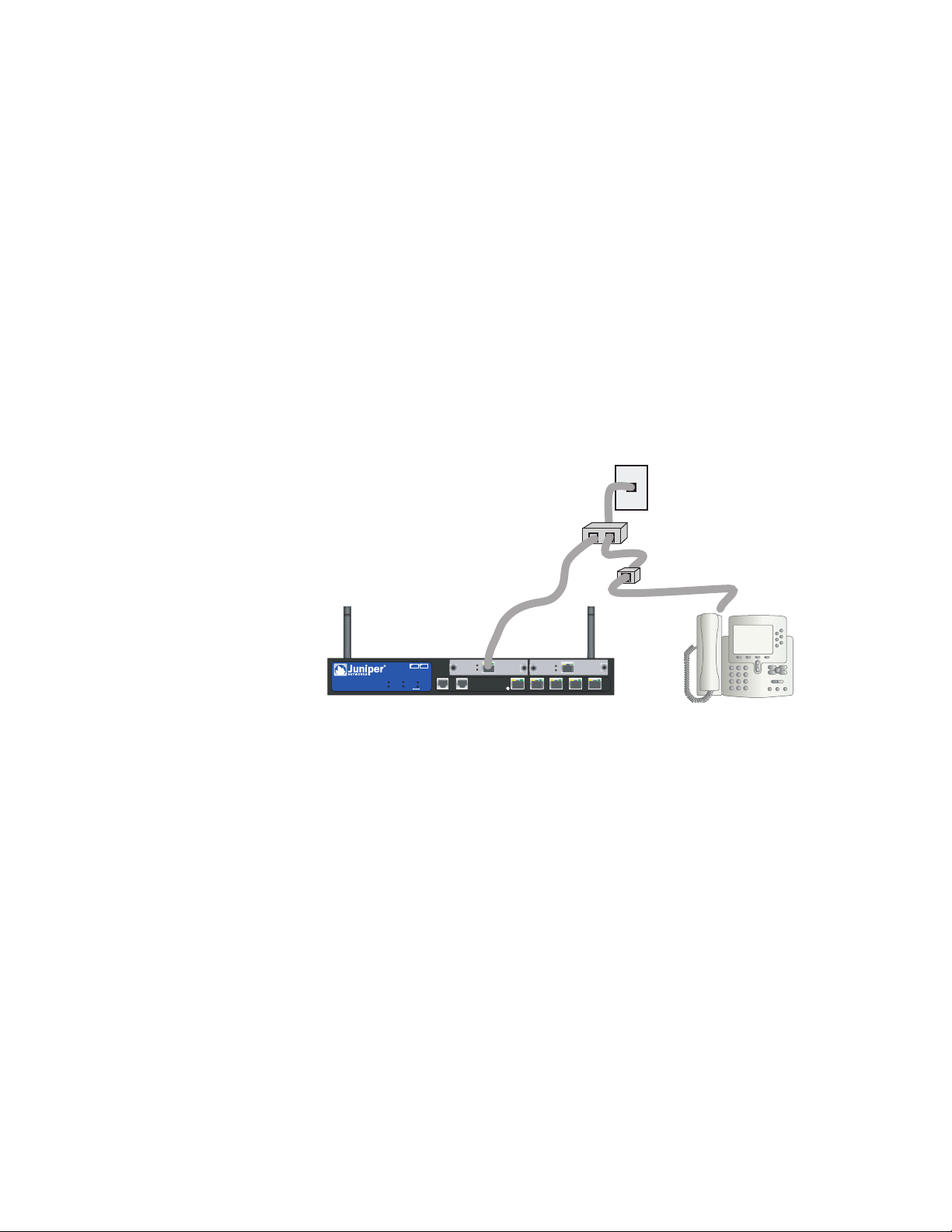
Figure 6 shows an example of a microfilter and a splitter that you install on your
site. (You must obtain the appropriate microfilters or splitters from your service
provider.)
Figure 6: Installing a Microfilter and Splitter on Your Network
New Graphic Needed
DATA VOICE
ADSL 2/2+
SYNC
TX/RX
TX/RX
10/100
10/100
0/0
0/1
0/2
LINK
10/100
10/100
10/100
0/4
0/5
SSG 20
ADSL 2+
12
POWER
PIM 1
802.11a
PIM 2
STATUS
b/g
WLAN
SYNC
TXRX
CONSOLEAUX
Connecting Other Mini PIMs
To connect the mini PIMs to a device, perform the following steps:
1. Have ready a length of the type of cable used by the interface.
2. Insert the cable connector into the cable-connector port on the interface
faceplate.
3. Arrange the cable as follows to prevent it from dislodging or developing stress
points:
a. Secure the cable so that it is not supporting its own weight as it hangs to
the floor.
b. Place any excess cable out of the way in a neatly coiled loop.
c. Use fasteners to maintain the shape of the cable loops.
To configure the ISDN, E1, T1, or V.92 Mini PIM, see “Mini PIM Configuration” on
page 30.
Connect the Device to a Network 15
 Loading...