


SRX650 Services Gateway Quick Start
Use the instructions in this quick start to help you connect the SRX650 Services
Gateway to your network. For details, see the SRX650 Services Gateway Hardware
Guide at http://
www.juniper.net/techpubs/hardware/junos-srx/srx650/index.html.
SRX650 Services Gateway Front Panel
SRX650 Services Gateway Back Panel
Connecting and Configuring the SRX Series Device
Use the instructions below to connect and set up the SRX650 Services Gateway to
protect your network. Refer to the LEDs on the front and back panels of the device to
help you determine the status of the device.
Task 1: Overview
The SRX650 Services Gateway is a security device that requires these basic
configuration settings to function:
n Interfaces must be assigned IP addresses.
n Interfaces must be bound to zones.
n All interfaces must be configured as Layer 3 interfaces.
n Policies must be configured between zones to permit or deny traffic.
n Source NAT rules must be set.
The device has the following default configuration set when you power it on for the first
time
. To be able to use the device, you do not need to perform any initial configuration.
Factory-Default Settings:
Factory-Default Settings for Security Policies:
Factory-Default Settings for NAT Rule:
Callout Description Callout Description
1 Mounting brackets 7 GPIM/XPIM slots
2 ALARM LED 8 POWER LED
3 FAN LED 9 HA SYS LED
4 SRE/ACE LED 1.0 10 SRE/ACE LED 0 (applies to Services and
Routing Engine models only)
5 ESD outlet 11 SRE/ACE LED 1.1
6 10/100/1000 Ethernet ports 12 Power button
650
g032700
2 4 6
3 5
7
1
8
9 10
11
12
DC OK AC OK
g032703
1 2 3
11
4
5
10
76 8 9
Callout Description Callout Description
1 Power supply slots 7 SRE LEDs
2 Multi-use processing slot 8 AUX port
3 SRE slot 0 (shown with Services and
Routing Engine model installed)
9 Console port
4 Fan tray 10 External CompactFlash slot
5 Air filter (behind fan tray) 11 2 USB ports
6 Reset Config button
Interface Security Zone DHCP State IP Address
ge-0/0/0 Untrust Client Dynamically assigned
ge-0/0/1 Trust Server 192.168.1.1/24
ge-0/0/2 Trust Server 192.168.2.1/24
ge-0/0/3 Trust Server 192.168.3.1/24
Source Zone Destination Zone Policy Action
timrePtsurtnUtsurT
Source Zone Destination Zone Policy Action
tsurtnUtsurT
Source NAT to untrust zone interface
Page 2
Task 2: Connect the Power Cable and a Power Source
Connect the power cable to the device and a power source. We recommend using a
surge protector. Note the following indications:
POWER LEDs (solid green) on front and back panels: The device is receiving power.
STATUS LED (solid green) on back panel: The device is operating normally.
ALARM LED (amber) on front panel: The device is operating normally, and may
glow amber as a rescue configuration has not been set. This is not a panic condition.
NOTE: After a rescue configuration has been set, an amber ALARM LED indicates a
minor alarm, and a solid red ALARM LED indicates that a major problem exists on the
services gateway.
IMPORTANT:
You must allow the device between 5 and 7 minutes to boot up after you
have powered it on. Wait until the STATUS LED is solid green before proceeding to Task 3.
Task 3: Connect the Management Device
Connect the management device to the services gateway using either of the following
methods:
Connect an RJ-45 (Ethernet cable) from the ge-0/0/1 port on the front panel to the
Ethernet port on the management device (workstation or laptop). We recommend
this connection method. If you are using this method to connect, proceed with Task 4.
Connect an RJ-45 (Ethernet cable) from the port labeled CONSOLE to the DB-9
adapter, which then connects to the serial port on the management device. (Serial
port settings: 9600 8-N-1-N).
If you are using this method to connect, proceed with the CLI configuration
instructions available in the Getting Started Guide for the Branch SRX Series at
http://www.juniper.net/techpubs/en_US/release-independent/junos/
information-products/pathway-pages/srx-series/product/index.html.
Task 4: Ensure That the Management Device Acquires an IP Address
After you connect the management device to the services gateway, the DHCP server
process on the services gateway will assign an IP address automatically to the
management device. Ensure that the management device acquires an IP address on the
192.168.1/24 subnetwork (other than 192.168.1.1) from the device.
NOTE: The services gateway functions as a DHCP server and will assign an IP address
to the management device.
If an IP address is not assigned to the management device, manually configure an
IP address in the 192.168.1.0/24 subnetwork while the management device is still
connected to the ge-0/0/1 port. Do not assign the 192.168.1.1 IP address to the
management device, as this IP address is assigned to the device.
When an SRX650 Services Gateway is powered on for the first time, it boots using
the factory-default configuration.
Task 5: Ensure That an IP Address Is Assigned to the Services Gateway
Use one of the following methods to obtain an IP address on the services gateway:
Method 1: Obtaining a Dynamic IP Address on Your Services Gateway
Use the port labeled 0/0 (interface ge-0/0/0) to connect to your Internet Service
Provider (ISP) Your ISP will assign an IP address using the DHCP process. if you
use this method, when you get to Task 8, skip steps 1 through 4.
Method 2: Obtaining a Static IP Address on Your Services Gateway
Use the port labeled 0/0 (interface ge-0/0/0) to connect to your Internet Service
Provider (ISP) Your ISP will have provided a static IP address. You will not receive
an IP address using the DHCP process. If you used this method, you must configure
the static IP address on the services gateway as described in Task 8, steps 1
through 4.
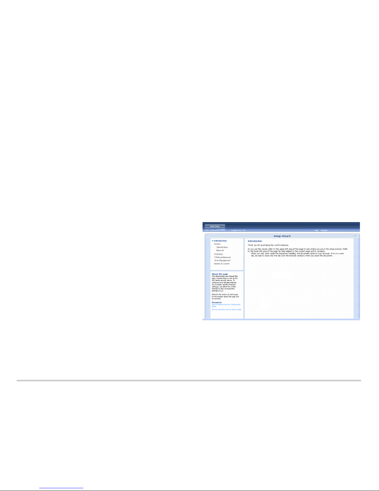
Task 6: Access the J-Web Interface
1. Launch a Web browser from the management device.
2. Type http://192.168.1.1 in the URL address field.
3. Specify the default username as root. Do not enter any value in the Password field.
4. Click Log In. The J-Web Setup Wizard page appears:
Task 7: Configure the Basic Settings
1. Click Start at the bottom of the introduction page. You can configure the basic
settings, such as hostname, domain name, and root password, for your services
gateway.
NOTE: All network and management access settings are optional.
All fields marked with an asterisk (*) are required.
 Loading...