

Juniper SRX5K-SCB, SRX5K-SPC-2-10-40, SRX5K-SPC-4-15-320, SRX5K-4XGE-XFP, SRX5K-40GE-SFP User Manual
...
SRX5600 and SRX5800
Services Gateway Card Guide
December 2012
Contents
SRX5600 and SRX5800 Services Gateway Card Overview . . . . . . . . . . . . . . . . . . 2
Cards Supported on SRX5600 and SRX5800 Services Gateways . . . . . . . . . . . . . 2
Services Processing Card SRX5K-SPC-2-10-40 . . . . . . . . . . . . . . . . . . . . . . . . . . . 4
Services Processing Card SRX5K-SPC-4-15-320 . . . . . . . . . . . . . . . . . . . . . . . . . . . 8
Switch Control Board SRX5K-SCB . . . . . . . . . . . . . . . . . . . . . . . . . . . . . . . . . . . . . . 12
I/O Card SRX5K-4XGE-XFP . . . . . . . . . . . . . . . . . . . . . . . . . . . . . . . . . . . . . . . . . . . 15
I/O Card SRX5K-40GE-SFP . . . . . . . . . . . . . . . . . . . . . . . . . . . . . . . . . . . . . . . . . . . 17
Flex I/O Card SRX5K-FPC-IOC . . . . . . . . . . . . . . . . . . . . . . . . . . . . . . . . . . . . . . . . . 19
Flex I/O Card Port Module SRX-IOC-16GE-TX . . . . . . . . . . . . . . . . . . . . . . . . . . . . . 21
Flex I/O Card Port Module SRX-IOC-16GE-SFP . . . . . . . . . . . . . . . . . . . . . . . . . . . 23
Flex I/O Card Port Module SRX-IOC-4XGE-XFP . . . . . . . . . . . . . . . . . . . . . . . . . . . 25
Routing Engine SRX5K-RE-13-20 . . . . . . . . . . . . . . . . . . . . . . . . . . . . . . . . . . . . . . 27
Handling and Storing SRX5600 and SRX5800 Services Gateway Cards . . . . . . 30
SRX5600 and SRX5800 Services Gateway Card Terminology . . . . . . . . . . . 30
Handling an SRX5600 or SRX5800 Services Gateway Card . . . . . . . . . . . . . 31
Storing an SRX5600 or SRX5800 Services Gateway Card . . . . . . . . . . . . . . 33
SRX Series Documentation and Release Notes . . . . . . . . . . . . . . . . . . . . . . . . . . . 33
Requesting Technical Support . . . . . . . . . . . . . . . . . . . . . . . . . . . . . . . . . . . . . . . . . 33
Self-Help Online Tools and Resources . . . . . . . . . . . . . . . . . . . . . . . . . . . . . . 34
Opening a Case with JTAC . . . . . . . . . . . . . . . . . . . . . . . . . . . . . . . . . . . . . . . . 34
Revision History . . . . . . . . . . . . . . . . . . . . . . . . . . . . . . . . . . . . . . . . . . . . . . . . . . . . 34
1Copyright © 2013, Juniper Networks, Inc.

SRX5600 and SRX5800 Services Gateway Card Guide
SRX5600 and SRX5800 Services Gateway Card Overview
The cards described in this guide let you upgrade and customize your SRX5600 or
SRX5800 Services Gateway to suit the needs of your network. The following types of
cards are available for the SRX5600 and SRX5800 Services Gateways:
•
I/O cards (IOCs) provide additional physical network connections to the services
gateway. Their primary function is to deliver data packets arriving on the physical ports
to the Services Processing Cards (SPCs) and to forward data packets out the physical
ports after services processing.
•
Flex IOCs have two slots for port modules that add additional physical network
connections to the services gateway. Like IOCs, their primary function is to deliver data
packets arriving on the physical ports to the SPCs and to forward data packets out the
physical ports after services processing.
•
Services Processing Cards (SPCs) provide the processing power to run integrated
services such as firewall, IPsec and IDP. All traffic traversing the services gateway is
passed to an SPC to have services processing applied to it.
•
SwitchControlBoards (SCBs) power on and power off IOCs and SPCs; controlclocking
and system resets; and control booting, monitor, and system functions. Each SCB has
a slot in the front panel for a Routing Engine.
Although the following modules are not cards in the sense of having a form-factor that
fits the card cage of the SRX5600 and SRX5800 Services Gateway, this guide also
addresses the following modules that fit into certain SRX5600 and SRX5800 Services
Gateway cards:
•
Routing Engines fit into slots in SCBs and maintain the routing tables, manage the
routing protocols used on the device, control the device interfaces and some chassis
components, and provide the interface for system management and user access to
the device.
•
Port modules fit into slots in Flex IOCs and add additional physical network interface
ports to the services gateway.
Cards Supported on SRX5600 and SRX5800 Services Gateways
Table 1 on page 2 describes the cards and other modules supported on the SRX5600
and SRX5800 Services Gateways.
Table 1: Supported Cards for SRX5600 and SRX5800 Services Gateways
Earliest Supported Junos OS
ReleaseCard Name and Model Number
SPCs
9.2“Services Processing Card SRX5K-SPC-2-10-40” on page 4
12.1X44-D10“Services Processing Card SRX5K-SPC-4-15-320” on page 8
Copyright © 2013, Juniper Networks, Inc.2

Cards Supported on SRX5600 and SRX5800 Services Gateways
Table 1: Supported Cards for SRX5600 and SRX5800 Services Gateways (continued)
Earliest Supported Junos OS
ReleaseCard Name and Model Number
IOCs and Flex IOCs
9.2“I/O Card SRX5K-40GE-SFP” on page 17
9.2“I/O Card SRX5K-4XGE-XFP” on page 15
10.2“Flex I/O Card SRX5K-FPC-IOC” on page 19
SCBs
9.2“Switch Control Board SRX5K-SCB” on page 12
Other modules
10.2“Flex I/O Card Port Module SRX-IOC-16GE-SFP” on page 23
10.2“Flex I/O Card Port Module SRX-IOC-16GE-TX” on page 21
10.2“Flex I/O Card Port Module SRX-IOC-4XGE-XFP” on page 25
9.2“Routing Engine SRX5K-RE-13-20” on page 27
3Copyright © 2013, Juniper Networks, Inc.
SRX5600 and SRX5800 Services Gateway Card Guide
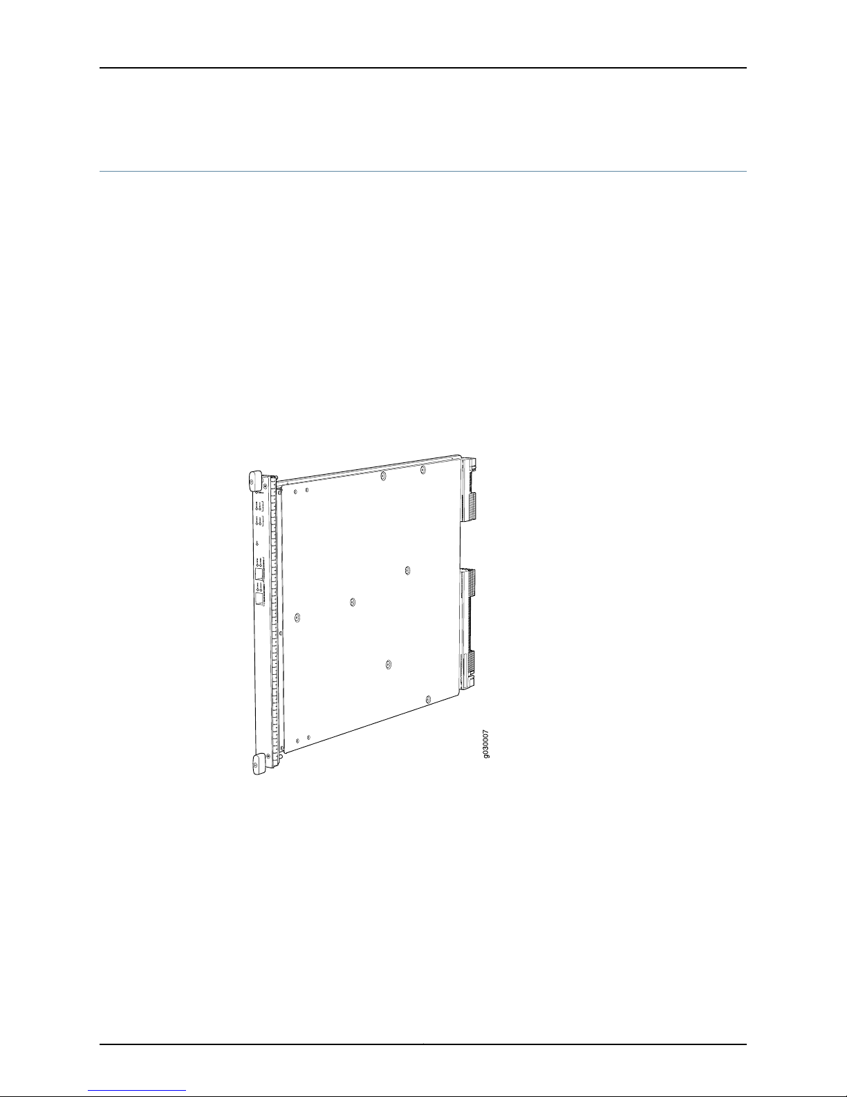
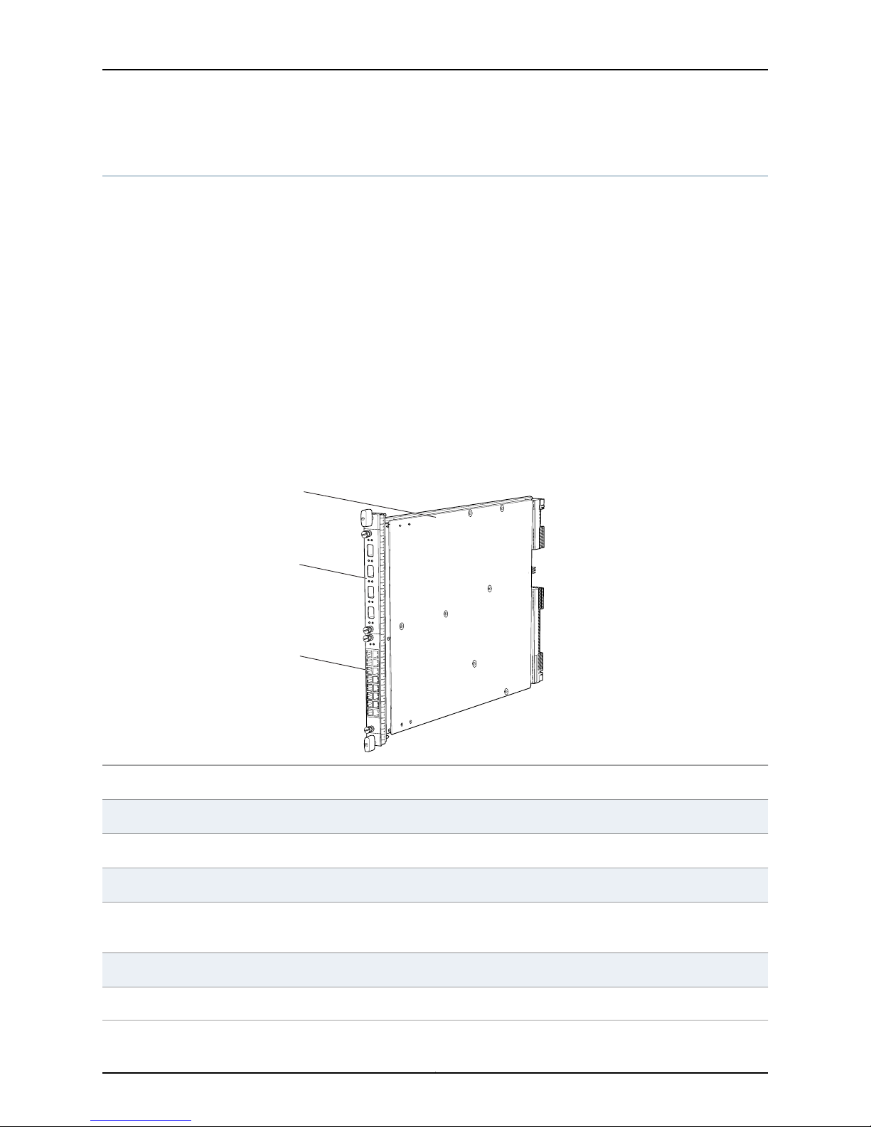
Services Processing Card SRX5K-SPC-2-10-40
The SRX5K-SPC-2-10-40 Services Processing Card (SPC) contains two Services
Processing Units (SPUs), which provide the processing power to run integrated services
such as firewall, IPsec, and IDP (see Figure 1 on page 4). All traffic traversing the services
gateway is passed to an SPU to have services processing applied to it. Traffic is
intelligently distributed by I/O cards (IOCs) to SPUs for services processing.
The services gateway must have at least one SPC installed. You can install additional
SPCs to increase services processing capacity.
You can install SPCs in any of the slots that are not reserved for Switch Control Boards
(SCBs). If a slot is not occupied by a card, you must install a blank panel to shield the
empty slot and to allow cooling air to circulate properly through the device.
Figure 1 on page 4 shows a typical SPC supported on the services gateway.
Figure 1: Services Processing Card SRX5K-SPC-2-10-40
Each SPC consists of the following components:
•
SPC cover, which functions as a ground plane and a stiffener.
•
Two small form-factor pluggable (SFP) chassis cluster control ports for connecting
multiple devices into a redundant chassis cluster. See Junos OS Security Configuration
Guide for more information about connecting and configuring redundant chassis
clusters.
Copyright © 2013, Juniper Networks, Inc.4

Services Processing Card SRX5K-SPC-2-10-40
NOTE: We strongly recommend the use of Juniper Networks SFP
transceivers. We cannot guarantee correct operation if other transceivers
are used. The transceiver type can be different in each port, as long as a
supported part number is used.
•
Fabric interfaces.
•
Two Gigabit Ethernet interfaces that allow control information, route information, and
statistics to be sent between the Routing Engine and the CPU on the SPCs.
•
Two interfaces from the SCBs that enable the boards to be powered on and controlled.
•
Physical SPC connectors.
•
Midplane connectors and power circuitry.
•
Processor subsystem, which includes a 1.2-GHz CPU, system controller, and 1 GB of
SDRAM.
•
LEDs on the faceplate that indicate the SPC and SPU status.
Cables and
connectors
Supported Slots
SPC with two SPUsDescription
•
Junos OS Release 9.2 and laterSoftware release
CHASSIS CLUSTER CONTROL 0 and CHASSIS CLUSTER CONTROL 1–SFP ports for control links in
chassis cluster configurations.
NoneControls
•
SRX5600–Any slot except bottom slots 0 or 1
•
SRX5800–Any slot except center slots 0, 1, or 2/6
Maximum 351 WPower Requirement
Approximately 13 lb (5.9 kg)Weight
5Copyright © 2013, Juniper Networks, Inc.

SRX5600 and SRX5800 Services Gateway Card Guide
LEDs
OK/FAIL LED, one bicolor:
•
Steady green–The SPC is operating normally.
•
Red–The SPC has failed and is not operating normally.
•
Off–The SPC is powered down.
STATUS LED, one tricolor for each of the two SPUs SPU 0 and SPU 1:
•
Green–The SPU is operating normally.
•
Amber–The SPU is initializing.
•
Red–The SPU has encountered an error or a failure.
•
Off–The SPU is offline. If all four SPUs are offline, it is safe to remove the SPC from the chassis.
SERVICE LED, one bicolor for each of the two SPUs, SPU 0 and SPU 1:
•
Green–Service is running on the SPU under acceptable load.
•
Amber–Service on the SPU is overloaded.
•
Off–Service is not running on the SPU.
HA LED, one tricolor:
•
Green–Clustering is operating normally. All cluster members and monitored links are available, and
no error conditions are detected.
•
Red–A critical alarm is present on clustering. A cluster member is missing or unreachable, or the
other node is no longer part of a cluster because it has been disabled by the dual membership and
detection recovery process in reaction to a control link or fabric link failure.
•
Amber–All cluster members are present, but an error condition has compromised the performance
and resiliency of the cluster. The reduced bandwidth could cause packets to be dropped or could
result in reduced resiliency because a single point of failure might exist. The error condition might
be caused by:
•
The loss of chassis cluster links which causes an interface monitoring failure.
•
An error in an SPU or NPU.
•
Failure of the spu-monitoring or cold-sync-monitoring processes.
•
A chassis cluster IP monitoring failure.
LINK/ACT LED, one for each of the two ports CHASSIS CLUSTER CONTROL 0 and CHASSIS CLUSTER
CONTROL 1:
•
Green–Chassis cluster control port link is active.
•
Off–No link.
ENABLE LED, one for each of the two ports CHASSIS CLUSTER CONTROL 0 and CHASSIS CLUSTER
CONTROL 1:
•
Green–The chassis cluster control port is enabled.
•
Off–The chassis cluster control port is disabled.
Copyright © 2013, Juniper Networks, Inc.6
OK/
F
AIL
TUNNEL
LINK
1/0
TUNNEL
LINK
0/0
TUNNEL
LINK
2/0
TUNNEL
LINK
3/0
g004067
AA567 8
Serial number
ID label
Services Processing Card SRX5K-SPC-2-10-40
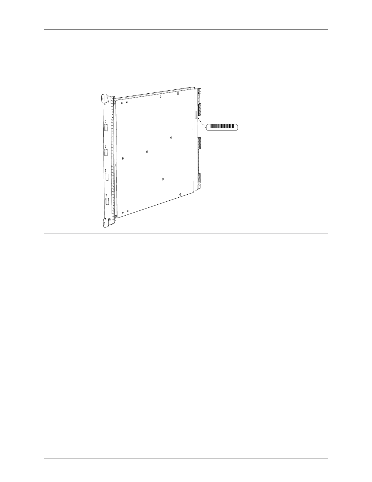
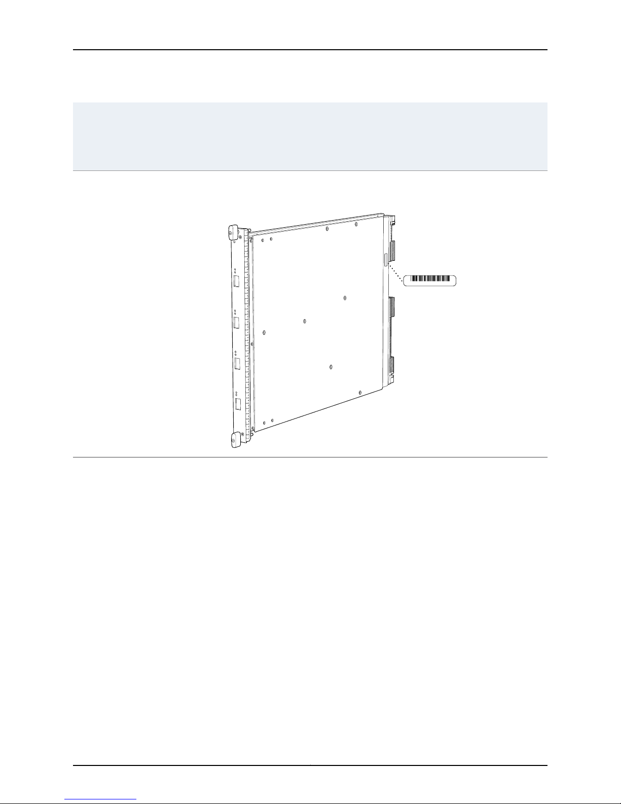
Serial Number
Location
The serial number label is located as shown in Figure 2 on page 7.
Figure 2: Serial Number Label (IOC Shown, Other Cards Similar)
7Copyright © 2013, Juniper Networks, Inc.
g030302
SRX5600 and SRX5800 Services Gateway Card Guide
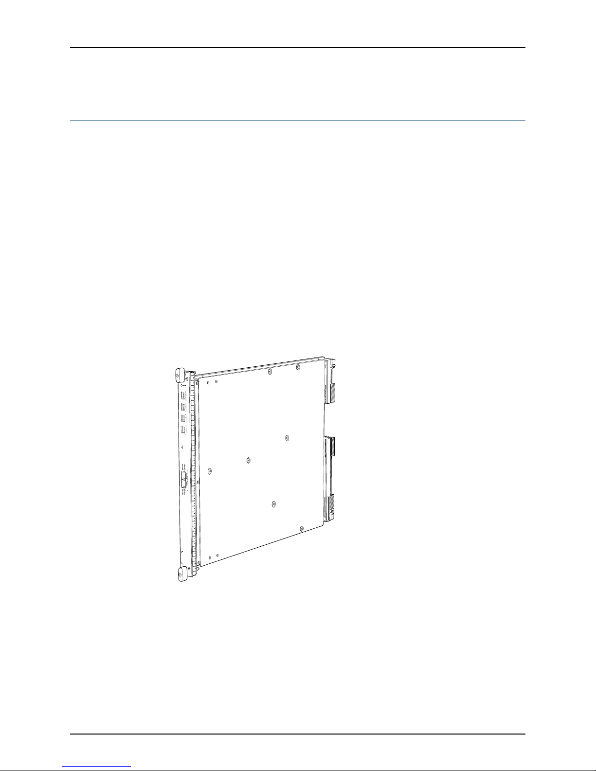
Services Processing Card SRX5K-SPC-4-15-320
The SRX5K-SPC-4-15-320 Services Processing Card (SPC) contains four Services
Processing Units (SPUs), which provide the processing power to run integrated services
such as firewall, IPsec, and IDP (see Figure 3 on page 8). All traffic traversing the services
gateway is passed to an SPU to have services processing applied to it. Traffic is
intelligently distributed by I/O cards (IOCs) to SPUs for services processing.
The services gateway must have at least one SPC installed. You can install additional
SPCs to increase services processing capacity.
You can install SPCs in any of the slots that are not reserved for Switch Control Boards
(SCBs). If a slot is not occupied by a card, you must install a blank panel to shield the
empty slot and to allow cooling air to circulate properly through the device.
If your services gateway contains a mix of SRX5K-SPC-4-15-320 SPCs and earlier
SRX5K-SPC-2-10-40 SPCs, an SRX5K-SPC-4-15-320 SPC must occupy the
lowest-numbered slot of any SPC in the chassis. This configuration ensures that the
center point (CP) function is performed by the faster and higher-performance SPC type.
Figure 3: Services Processing Card SRX5K-SPC-4-15-320
Each SPC consists of the following components:
•
SPC cover, which functions as a ground plane and a stiffener.
•
Two small form-factor pluggable (SFP) chassis cluster control ports for connecting
multiple devices into a redundant chassis cluster. See Junos OS Security Configuration
Guide for more information about connecting and configuring redundant chassis
clusters.
Copyright © 2013, Juniper Networks, Inc.8

Services Processing Card SRX5K-SPC-4-15-320
NOTE: We strongly recommend the use of Juniper Networks SFP
transceivers. We cannot guarantee correct operation if other transceivers
are used. The transceiver type can be different in each port, as long as a
supported part number is used.
•
Fabric interfaces.
•
Two Gigabit Ethernet interfaces that allow control information, route information, and
statistics to be sent between the Routing Engine and the CPU on the SPCs.
•
Two interfaces from the SCBs that enable the boards to be powered on and controlled.
•
Physical SPC connectors.
•
Midplane connectors and power circuitry.
•
Processor subsystem, which includes a 1.2-GHz CPU, system controller, and 1 GB of
SDRAM.
•
LEDs on the faceplate that indicate the SPC and SPU status.
Cables and
connectors
Supported Slots
Power
Requirement
SPC with four SPUsDescription
•
Junos OS Release 12.1X44-D10 and laterSoftware release
CHASSIS CLUSTER CONTROL 0 and CHASSIS CLUSTER CONTROL 1–SFP ports for control links in chassis
cluster configurations.
NoneControls
•
SRX5600–Any slot except bottom slots 0 or 1
•
SRX5800–Any slot except center slots 0 or 1
450 W typical, 585 W maximum
NOTE:
•
You must have high-capacity power supplies (either AC or DC) and high-capacity fan trays installed
in the services gateway in order to install and use SRX5K-SPC-4-15-320 SPCs. If you do not have
high-capacity power supplies and fan trays installed, the services gateway will log an alarm condition
when it recognizes the SRX5K-SPC-4-15-320 SPCs.
•
On SRX5600 Services Gateways with AC power supplies, we recommend that you use high-line (220v)
input power to ensure the device has adequate power to support SRX5K-SPC-4-15-320 SPCs.
Approximately 18 lb (8.3 kg)Weight
9Copyright © 2013, Juniper Networks, Inc.

SRX5600 and SRX5800 Services Gateway Card Guide
LEDs
OK/FAIL LED, one bicolor:
•
Steady green–The SPC is operating normally.
•
Red–The SPC has failed and is not operating normally.
•
Off–The SPC is powered down.
STATUS LED, one tricolor for each of the four SPUs SPU 0 through SPU 3:
•
Green–The SPU is operating normally.
•
Amber–The SPU is initializing.
•
Red–The SPU has encountered an error or a failure.
•
Off–The SPU is offline. If all four SPUs are offline, it is safe to remove the SPC from the chassis.
SERVICE LED, one bicolor for each of the four SPUs SPU 0 through SPU 3:
•
Green–Service is running on the SPU under acceptable load.
•
Amber–Service on the SPU is overloaded.
•
Off–Service is not running on the SPU.
HA LED, one tricolor:
•
Green–Clustering is operating normally. All cluster members and monitored links are available, and no
error conditions are detected.
•
Red–A critical alarm is present on clustering. A cluster member is missing or unreachable, or the other
node is no longer part of a cluster because it has been disabled by the dual membership and detection
recovery process in reaction to a control-link or fabric-link failure.
•
Amber–All cluster members are present, but an error condition has compromised the performance
and resiliency of the cluster. The reduced bandwidth could cause packets to be dropped or could result
in reduced resiliency because a single point of failure might exist. The error condition might be caused
by:
•
The loss of chassis cluster links which causes an interface monitoring failure.
•
An error in an SPU or NPU.
•
Failure of the spu-monitoring or cold-sync-monitoring processes.
•
A chassis cluster IP monitoring failure.
•
Off–The node is not configured for clustering or it has been disabled by the dual membership and
detection recovery process in reaction to a control link or fabric link failure.
LINK/ACT LED, one for each of the two ports CHASSIS CLUSTER CONTROL 0 and CHASSIS CLUSTER
CONTROL 1:
•
Green–Chassis cluster control port link is active.
•
Off–No link.
ENABLE LED, one for each of the two ports CHASSIS CLUSTER CONTROL 0 and CHASSIS CLUSTER
CONTROL 1:
•
Green–The chassis cluster control port is enabled.
•
Off–The chassis cluster control port is disabled.
Copyright © 2013, Juniper Networks, Inc.10
OK/
F
AIL
TUNNEL
LINK
1/0
TUNNEL
LINK
0/0
TUNNEL
LINK
2/0
TUNNEL
LINK
3/0
g004067
AA567 8
Serial number
ID label
Services Processing Card SRX5K-SPC-4-15-320
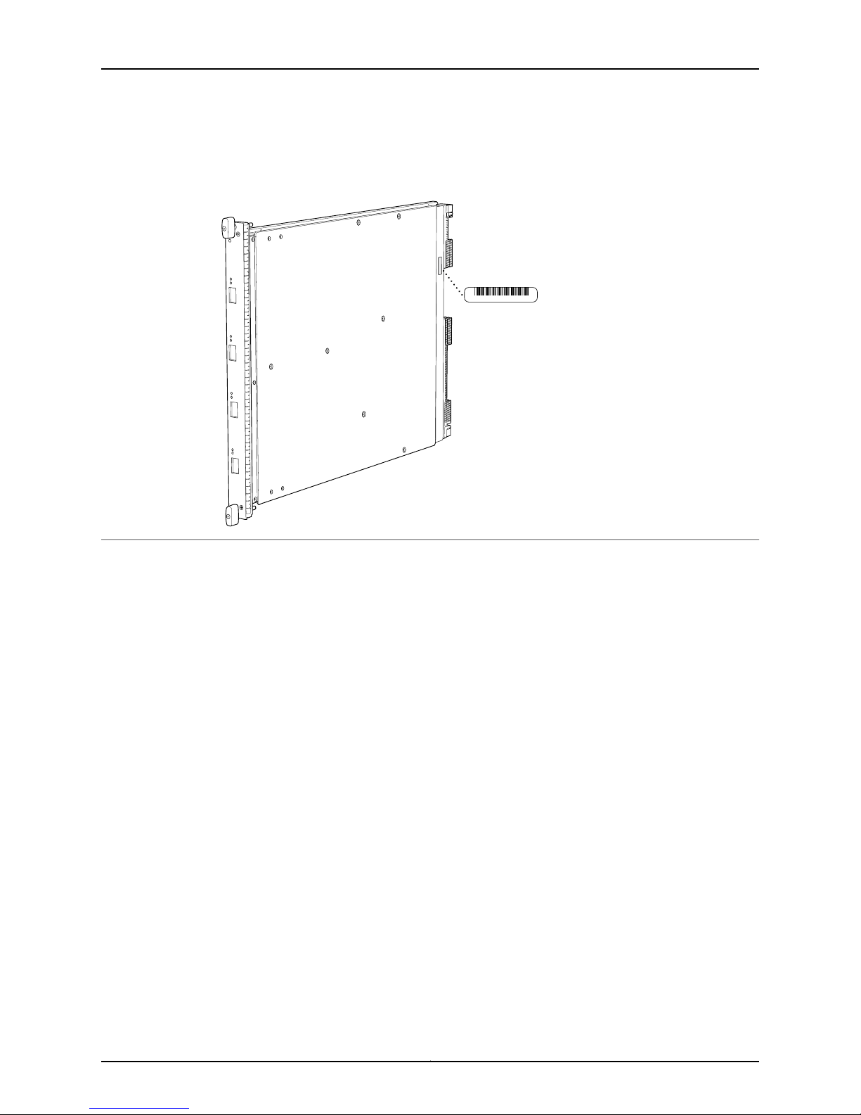
Serial Number
Location
Documentation
The serial number label is located as shown in Figure 4 on page 11.
Figure 4: Serial Number Label (IOC Shown, Other Cards Similar)
Related
Cards Supported on SRX5600 and SRX5800 Services Gateways on page 2•
11Copyright © 2013, Juniper Networks, Inc.

SRX5600 and SRX5800 Services Gateway Card Guide
Switch Control Board SRX5K-SCB
The SRX5K-SCB SwitchControl Board (SCB) (Figure 5 on page 12) performs the following
functions:
•
Powers on and powers off I/O cards (IOCs) and Services Processing Cards (SPCs)
•
Controls clocking, system resets, and booting
•
Monitors and controls system functions, including fan speed, board power status, PDM
status and control, and the system front panel
•
Provides interconnections to all the IOCs within the chassis through the switch fabrics
integrated into the SCB
The SRX5600 Services Gateway must have at least one SCB installed, and you can
install a second SCB for switch fabric redundancy.The SRX5800 Services Gateway must
have at least two SCBs installed, and you can install a third SCB for switch fabric
redundancy.
When the SCB is part of a host subsystem, the Routing Engine is installed directly into a
slot on the faceplate of the SCB .
Figure 5: Switch Control Board SRX5K-SCB
Each SCB consists of the following components:
•
Chassis management Ethernet switch.
•
I2C bus logic, used for low-level communication with each component.
•
Component redundancy circuitry.
Copyright © 2013, Juniper Networks, Inc.12

Switch Control Board SRX5K-SCB
•
Gigabit Ethernet switch that is connected to the embedded CPU complex on all
components.
•
Switch fabric—Provides the switching functions for the IOCs.
•
Control FPGA—Provides the Peripheral Component Interconnect (PCI) interface to
the Routing Engine.
•
1000Base-T Ethernet controller—Provides a 1-Gbps Ethernet link betweenthe Routing
Engines.
•
Ethernet switch—Provides 1-Gbps link speeds between the Routing Engine and the
IOCs.
•
Circuits for chassis management and control.
•
Power circuits for the Routing Engine and SCB.
SCB with slot for Routing EngineDescription
•
Junos OS Release 9.2 and laterSoftware release
Supported Slots
LEDs
Slot for Routing EngineCables and connectors
NoneControls
•
SRX5600–Only bottom slots 0 and 1
•
SRX5800–Only center slots 0, 1, and 2/6
150 WPower Requirement
Approximately 10 lb (4.5 kg)Weight
OK/FAIL LED, one bicolor:
•
Green–The SCB is operating normally.
•
Red–The SCB has failed and is not operating normally.
•
Off–The SCB is powered down.
FABRIC ONLY LED:
•
Green–The SCB is operating in fabric-only mode.
•
Off–The SCB is operating in fabric/control board mode.
FABRIC ACTIVE LED:
•
Green–The fabric is in active mode.
13Copyright © 2013, Juniper Networks, Inc.

g004068
Serial number
ID label
SRX5600 and SRX5800 Services Gateway Card Guide
Serial Number Location
The serial number label is located as shown in Figure 6 on page 14.
Figure 6: SCB Serial Number Label
Related
Documentation
Cards Supported on SRX5600 and SRX5800 Services Gateways on page 2•
• Routing Engine SRX5K-RE-13-20 on page 27
Copyright © 2013, Juniper Networks, Inc.14

I/O Card SRX5K-4XGE-XFP
OK/FAIL
TUNNEL
LINK
1/0
TUNNEL
LINK
0/0
TUNNEL
LINK
2/0
TUNNEL
LINK
3/0
g030301
The SRX5K-4XGE-XFP I/O card (IOC) supports four 10-Gigabit Ethernet ports (see Figure
7 on page 15). The IOC assembly combines packet forwarding and Ethernet interfaces
on a single board, with four 10-Gbps Packet Forwarding Engines. Each Packet Forwarding
Engine consists of one I-chip for Layer 3 processing and one Layer 2 network processor.
The IOCs interface with the power supplies and Switch Control Boards (SCBs).
You must install at least one IOC in the services gateway. The IOC can be of any of the
available IOC or Flex IOC types.
You can install IOCs in any of the slots that are not reserved for Switch Control Boards
(SCBs). If a slot is not occupied by a card, you must install a blank panel to shield the
empty slot and to allow cooling air to circulate properly through the services gateway.
Figure 7: IOC SRX5K-4XGE-XFP
I/O Card SRX5K-4XGE-XFP
Description
Supported Slots
•
I/O card with four 10-Gigabit Ethernet XFP ports
•
Maximum configurable MTU: 9192 bytes
•
Junos OS Release 9.2 and laterSoftware release
Four 10-Gbps XFP portsCables and connectors
NoneControls
•
SRX5600–Any slot except bottom slots 0 or 1
•
SRX5800–Any slot except center slots 0, 1, or 2/6
312 W typical, 365 W maximumPower Requirement
15Copyright © 2013, Juniper Networks, Inc.

OK/
F
AIL
TUNNEL
LINK
1/0
TUNNEL
LINK
0/0
TUNNEL
LINK
2/0
TUNNEL
LINK
3/0
g004067
AA567 8
Serial number
ID label
SRX5600 and SRX5800 Services Gateway Card Guide
Approximately 13 lb (5.9 kg)Weight
LEDs
Serial Number Location
OK/FAIL LED, one bicolor:
•
Steady green–The IOC is operating normally.
•
Red–The IOC has failed and is not operating normally.
•
Off–The IOC is powered down.
The serial number label is located as shown in Figure 8 on page 16.
Figure 8: Serial Number Label
Related
Cards Supported on SRX5600 and SRX5800 Services Gateways on page 2•
Documentation
Copyright © 2013, Juniper Networks, Inc.16

I/O Card SRX5K-40GE-SFP
OK/
F
AIL
0/0
0/5
2/0
2/5
1/0
1/5
3/0
3/5
g030300
The SRX5K-40GE-SFP I/O card (IOC) is optimized for Ethernet density and supports 40
Gigabit Ethernet ports (see Figure 9 on page 17). The IOC assembly combines packet
forwardingand Ethernet interfaces on a single board, with four 10-Gbps Packet Forwarding
Engines. Each Packet Forwarding Engine consists of one I-chip for Layer 3 processing
and one Layer 2 network processor. The IOCs interface with the power supplies and
Switch Control Boards (SCBs).
You must install at least one IOC in the services gateway. The IOC can be of any of the
available IOC or Flex IOC types.
You can install IOCs in any of the slots that are not reserved for Switch Control Boards
(SCBs). If a slot is not occupied by a card, you must install a blank panel to shield the
empty slot and to allow cooling air to circulate properly through the services gateway.
Figure 9: IOC SRX5K-40GE-SFP
I/O Card SRX5K-40GE-SFP
Description
Supported Slots
•
I/O card with 40 Gigabit Ethernet SFP ports
•
Maximum configurable MTU: 9192 bytes
•
Junos OS Release 9.2 and laterSoftware release
40 Gigabit Ethernet SFP portsCables and connectors
NoneControls
•
SRX5600–Any slot except bottom slots 0 or 1
•
SRX5800–Any slot except center slots 0, 1, or 2/6
17Copyright © 2013, Juniper Networks, Inc.

OK/
F
AIL
TUNNEL
LINK
1/0
TUNNEL
LINK
0/0
TUNNEL
LINK
2/0
TUNNEL
LINK
3/0
g004067
AA567 8
Serial number
ID label
SRX5600 and SRX5800 Services Gateway Card Guide
312 W typical, 365 W maximumPower Requirement
Approximately 13 lb (5.9 kg)Weight
LEDs
Serial Number Location
OK/FAIL LED, one bicolor:
•
Steady green–The IOC is operating normally.
•
Red–The IOC has failed and is not operating normally.
•
Off–The IOC is powered down.
The serial number label is located as shown in Figure 10 on page 18.
Figure 10: Serial Number Label (IOC Shown, Other Cards
Similar)
Related
Cards Supported on SRX5600 and SRX5800 Services Gateways on page 2•
Documentation
Copyright © 2013, Juniper Networks, Inc.18
Flex I/O Card SRX5K-FPC-IOC
g030286
Flex IOC
4x10GE-XFP
port module
in slot 0
16x1GE-TX
port module
in slot 1
The SRX5K-FPC-IOC Flex I/O card (Flex IOC) (Figure 11 on page 19) is an IOC with two
slots that accept port modules that add Ethernet ports to your services gateway. A Flex
IOC with installed port modules functions in the same way as a regular IOC, but allows
greater flexibility in adding different types of Ethernet ports to your services gateway.
Each Flex IOC has a processor subsystem, which includes a 1.2-GHz CPU, a system
controller, 1 GB SDRAM, and two Packet Forwarding Engines with a maximum throughput
of 10 Gbps each.
You must install at least one IOC in the services gateway. The IOC can be of any of the
available IOC or Flex IOC types.
You can install Flex IOCs in any of the slots that are not reserved for Switch Control
Boards (SCBs). If a slot is not occupied by a card, you must install a blank panel to shield
the empty slot and to allow cooling air to circulate properly through the services gateway.
Figure 11: Flex IOC with Typical Port Modules
Flex I/O Card SRX5K-FPC-IOC
Supported Slots
Flex IOC with slots for two port modulesDescription
•
Junos OS Release 9.5R1 and laterSoftware release
Slots for two port modulesCables and connectors
NoneControls
•
SRX5600–Any slot except bottom slots 0 or 1
•
SRX5800–Any slot except center slots 0, 1, or 2/6
312 W typical, 365 W maximum (includes port modules)Power Requirement
Approximately 10 lb (4.5 kg)Weight
19Copyright © 2013, Juniper Networks, Inc.
OK/
F
AIL
TUNNEL
LINK
1/0
TUNNEL
LINK
0/0
TUNNEL
LINK
2/0
TUNNEL
LINK
3/0
g004067
AA567 8
Serial number
ID label
SRX5600 and SRX5800 Services Gateway Card Guide
LEDs
Serial Number Location
OK/FAIL LED, one bicolor:
•
Steady green–The Flex IOC is operating normally.
•
Red–The Flex IOC has failed and is not operating normally.
•
Off–The Flex IOC is powered down.
The serial number label is located as shown in Figure 12 on page 20.
Figure 12: Serial Number Label (IOC Shown, Other Cards Similar)
Related
Documentation
Cards Supported on SRX5600 and SRX5800 Services Gateways on page 2•
• Flex I/O Card Port Module SRX-IOC-16GE-TX on page 21
• Flex I/O Card Port Module SRX-IOC-16GE-SFP on page 23
• Flex I/O Card Port Module SRX-IOC-4XGE-XFP on page 25
Copyright © 2013, Juniper Networks, Inc.20

Flex I/O Card Port Module SRX-IOC-16GE-TX
g030285
You use port modules and Flex I/O Cards (Flex IOCs) to add different combinations of
small form-factor pluggable transceiver (SFP), 10-gigabit SFP transceiver (XFP), and
copper ports to your services gateway to suit the specific needs of your network. The
SRX-IOC-16GE-TX port module (Figure 13 on page 21) installs into a Flex IOC to add
sixteen 10/100/1000 Ethernet RJ-45 copper ports.
Figure 13: Flex IOC Port Module SRX-IOC-16GE-TX
•
Description
Port module with sixteen 10/100/1000 Ethernet RJ45 ports
•
Maximum throughput: 10 Gbps
•
Oversubscription ratio: 1.6:1
•
Maximum configurable MTU: 9192 bytes
Flex I/O Card Port Module SRX-IOC-16GE-TX
Controls
LEDs
•
Junos OS Release 9.5R1 and laterSoftware release
Sixteen RJ-45 1-Gbps portsCables and connectors
ONLINE Button–The ONLINE button on the port module front panel toggles the port module
online and offline.
Either slot in SRX5K-FPC-IOC Flex IOCSupported Slots
Approximately 1.6 lb (0.7 kg)Weight
OK/FAIL LED, one bicolor:
•
Steady green–The port module is operating normally.
•
Red–The port module has failed and is not operating normally.
•
Off–The port module is powered down.
LINK LED, single color, one per port:
•
Steady green–The link is active.
•
Off–No link.
TX/RX LED, single color, one per port:
•
Blinking green–The port is receiving or transmitting data.
•
Off–No activity.
21Copyright © 2013, Juniper Networks, Inc.

g030305
JX0123
Serial number
ID label
SRX5600 and SRX5800 Services Gateway Card Guide
Serial Number Location
Related
Documentation
The serial number label is located as shown inFigure 14 on page 22.
Figure 14: Port Module SRX-IOC-16GE-TX Serial Number Label
Cards Supported on SRX5600 and SRX5800 Services Gateways on page 2•
• Flex I/O Card SRX5K-FPC-IOC on page 19
Copyright © 2013, Juniper Networks, Inc.22

Flex I/O Card Port Module SRX-IOC-16GE-SFP
g030271
You use port modules and Flex I/O Cards (Flex IOCs) to add different combinations of
small form-factor pluggable transceiver (SFP), 10-gigabit SFP transceiver (XFP), and
copper ports to your services gateway to suit the specific needs of your network. The
SRX-IOC-16GE-SFP port module (Figure 15 on page 23) installs into a Flex IOC to add
sixteen 10/100/1000 Ethernet SFP ports.
Figure 15: Flex IOC Port Module SRX-IOC-16GE-SFP
•
Description
Port module with 16 Gigabit Ethernet SFP ports
•
Maximum throughput: 10 Gbps
•
Oversubscription ratio: 1.6:1
•
Maximum configurable MTU: 9192 bytes
Flex I/O Card Port Module SRX-IOC-16GE-SFP
Controls
LEDs
•
Junos OS Release 9.5R1 and laterSoftware release
16 Gigabit Ethernet SFP portsCables and connectors
ONLINE Button–The ONLINE button on the port module front panel toggles the port module
online and offline
Either slot in SRX5K-FPC-IOC Flex IOCSupported Slots
Approximately 1.6 lb (0.7 kg)Weight
OK/FAIL LED, one bicolor:
•
Steady green–The port module is operating normally.
•
Red–The port module has failed and is not operating normally.
•
Off–The port module is powered down.
LINK LED, single color, one per port:
•
Steady green–The link is active.
•
Off–No link.
TX/RX LED, single color, one per port:
•
Blinking Green–The port is receiving or transmitting data.
•
Off–No activity.
23Copyright © 2013, Juniper Networks, Inc.

g030304
JX0123
Serial number
ID label
SRX5600 and SRX5800 Services Gateway Card Guide
Serial Number Location
Related
Documentation
The serial number label is located as shown in Figure 16 on page 24.
Figure 16: Port Module SRX-IOC-16GE-SFP Serial Number Label
Cards Supported on SRX5600 and SRX5800 Services Gateways on page 2•
• Flex I/O Card SRX5K-FPC-IOC on page 19
Copyright © 2013, Juniper Networks, Inc.24

Flex I/O Card Port Module SRX-IOC-4XGE-XFP
g030269
You use port modules and Flex I/O Cards (Flex IOCs) to add different combinations of
small form-factor pluggable transceiver (SFP), 10-gigabit SFP transceiver (XFP), and
copper ports to your services gateway to suit the specific needs of your network. The
SRX-IOC-4XGE-XFP port module (Figure 17 on page 25) installs into a Flex IOC to add
four 10-Gigabit Ethernet XFP ports.
Figure 17: Flex IOC Port Module SRX-IOC-4XGE-XFP
•
Description
Port module with four 10-Gigabit Ethernet XFP ports
•
Maximum throughput: 10 Gbps
•
Oversubscription ratio: 4:1
•
Maximum configurable MTU: 9192 bytes
Flex I/O Card Port Module SRX-IOC-4XGE-XFP
Controls
LEDs
•
Junos OS Release 9.5R1 and laterSoftware release
4 XFP Ethernet portsCables and connectors
ONLINE Button–The ONLINE button on the port module front panel toggles the port module
online and offline
Either slot in SRX5K-FPC-IOC Flex IOCSupported Slots
Approximately 1.6 lb (0.7 kg)Weight
OK/FAIL LED, one bicolor:
•
Steady green–The port module is operating normally.
•
Red–The port module has failed and is not operating normally.
•
Off–The port module is powered down.
LINK LED, single color, one per port:
•
Steady green–The link is active.
•
Off–No link.
25Copyright © 2013, Juniper Networks, Inc.

g030303
JX0123
Serial number
ID label
SRX5600 and SRX5800 Services Gateway Card Guide
Serial Number Location
Related
Documentation
The serial number label is located as shown in Figure 18 on page 26.
Figure 18: Port Module SRX-IOC-4XGE-XFP Serial Number Label
Cards Supported on SRX5600 and SRX5800 Services Gateways on page 2•
• Flex I/O Card SRX5K-FPC-IOC on page 19
Copyright © 2013, Juniper Networks, Inc.26

Routing Engine SRX5K-RE-13-20
The SRX5K-RE-13-20 Routing Engine (Figure 19 on page 27) is an Intel-based PC platform
that runs the Junos operating system (Junos OS). Software processes that run on the
Routing Engine maintain the routing tables, manage the routing protocols used on the
device, control the device interfaces, control some chassis components, and provide the
interface for system management and user access to the device.
Figure 19: Routing Engine
Routing Engine SRX5K-RE-13-20
You must install at least one Routing Engine in the services gateway. You can install a
second Routing Engine if both Routing Engines are running Junos OS Release 10.0 or
later. A second Routing Engine is required if you are using the dual chassis cluster control
link feature available in Junos OS Release 10.0 and later. The second Routing Engine
does not perform all the functions of a Routing Engine and does not improve resiliency
or redundancy. The second Routing Engine and the Switch Control Board (SCB) in which
it is installed do not constitute a host subsystem. The only function of the second Routing
Engine is to enable the hardware infrastructure that enables the chassis cluster control
1 port on the Services Processing Card (SPC) used for chassis cluster control links. If you
install only one Routing Engine in the services gateway, you must install it in the slot in
the front panel of SCB0. If you install a second Routing Engine to use the dual chassis
cluster control link feature, you install it in the slot in the front panel of SCB1.
The Routing Engine consists of the following components:
•
CPU—Runs Junos OS to maintain the services gateway's routing tables and routing
protocols. It has a Pentium-class processor.
•
DRAM—Provides storage for the routing and forwarding tables and for other Routing
Engine processes.
•
USB port—Provides a removable media interface through which you can install Junos
OS manually. Junos supports USB version 1.0.
•
Internal flash disk—Provides primary storage for software images, configuration files,
and microcode. The disk is a fixed compact flash and is inaccessible from outside the
services gateway.
27Copyright © 2013, Juniper Networks, Inc.

SRX5600 and SRX5800 Services Gateway Card Guide
•
Hard disk—Provides secondary storage for log files, memory dumps, and rebooting the
system if the internal compact flash disk fails.
•
HDD LED—Indicates disk activity for the hard disk drive.
•
Management ports—Each Routing Engine has one 10/100-Mbps Ethernet port for
connecting to a management network, and two asynchronous serial ports—one for
connecting to a console and one for connecting to a modem or other auxiliary device.
The interface ports are labeled AUX, CONSOLE, and ETHERNET.
•
EEPROM—Stores the serial number of the Routing Engine.
•
Extractor clips—Used for inserting and extracting the Routing Engine.
•
Captive screws—Secures the Routing Engine in place.
The Routing Engine boots from the storage media in this order: the USB device (if present),
then the internal flash disk, then the hard disk, then the LAN.
NOTE: For specific information about Routing Engine components (for
example, the amount of DRAM), issue the show chassis routing-engine
command.
Software release
Cables and connectors
Controls
Supported Slots
Routing Engine for SRX5600 and SRX5800 Services GatewaysDescription
•
Junos OS Release 9.2 and later
•
Junos OS Release 10.0 and later required to install a second Routing Engine
AUX—Connects the Routing Engine to a laptop, a modem, or another auxiliary device through a
cable with an RJ-45 connector.
CONSOLE—Connects the Routing Engine to a system console through a cable with an RJ-45
connector.
ETHERNET—Connects the Routing Engine through an Ethernet connection to a management LAN
(or any other device that plugs into an Ethernet connection) for out-of-band management.
•
RESET button—Reboots the Routing Engine when pressed
•
ONLINE/OFFLINE Button—Not supported in the current release
Front panel slot in an SCB installed in:
•
SRX5600: Bottom slots 0 or 1
•
SRX5800: Center slots 0 or 1
NOTE: The services gateway host subsystem Routing Engine must be installed in the SCB in slot
0. A Routing Engine installed in an SCB in slot 1 only enables dual control links in chassis cluster
configurations.
90 WPower Requirement
Approximately 2.4 lb (1.1 kg)Weight
Copyright © 2013, Juniper Networks, Inc.28

Routing Engine SRX5K-RE-13-20
LEDs
Serial Number Location
HDD LED:
•
Blinking green–The Routing Engine hard disk is functioning normally.
MASTER LED:
•
Blue–The Routing Engine is Primary.
NOTE: The SRX5600 and SRX5800 Services Gateways do not support a secondary or backup
Routing Engine, so the MASTER LED should always be lit.
OK/FAIL LED, one bicolor:
•
Off–The Routing Engine is operating normally.
•
Red–The Routing Engine has failed and is not operating normally.
ONLINE LED:
•
Blinking green–The Routing Engine is coming online.
•
Steady green–The Routing Engine is functioning normally.
The serial number label is located on the right side of the top of the Routing Engine as shown in
Figure 20 on page 29.
Figure 20: Routing Engine Serial Number Label
Related
Documentation
Cards Supported on SRX5600 and SRX5800 Services Gateways on page 2•
• Switch Control Board SRX5K-SCB on page 12
29Copyright © 2013, Juniper Networks, Inc.

SRX5600 and SRX5800 Services Gateway Card Guide
Handling and Storing SRX5600 and SRX5800 Services Gateway Cards
•
SRX5600 and SRX5800 Services Gateway Card Terminology on page 30
•
Handling an SRX5600 or SRX5800 Services Gateway Card on page 31
•
Storing an SRX5600 or SRX5800 Services Gateway Card on page 33
SRX5600 and SRX5800 Services Gateway Card Terminology
Regardless of orientation, this information uses the same terms for all four edges of the
card (see Figure 21 on page 30):
•
Faceplate—Edge of the card that has connectors to which you connect cables or
sockets in which you insert SFP or XFP transceivers.
•
Connectoredge—Edge opposite the faceplate;this edge has the connectors that attach
to the midplane.
•
Top edge—Edge at the top of the card when it is vertical.
•
Bottom edge—Edge at the bottom of the card when it is vertical.
NOTE: This terminology applies to SPCs, IOCs, and SCBs in addition to
Routing Engines and port modules.
Figure 21: Card Edges
Related
Cards Supported on SRX5600 and SRX5800 Services Gateways on page 2•
Documentation
Copyright © 2013, Juniper Networks, Inc.30

Handling an SRX5600 or SRX5800 Services Gateway Card
Handling an SRX5600 or SRX5800 Services Gateway Card
When carrying a card, you can hold it either vertically or horizontally.
NOTE: A card weighs up to 18.3 lb (8.3 kg). Be prepared to accept the full
weight of the card as you lift it.
To hold a card vertically:
1. Orient the card so that the faceplate faces you. To verify orientation, confirm that the
text on the card is right-side up and the EMI strip is on the right-hand side.
2. Place one hand around the card faceplate about a quarter of the way down from the
top edge. To avoid deforming the EMI shielding strip, do not press hard on it.
3. Place your other hand at the bottom edge of the card.
If the card is horizontal before you grasp it, place your left hand around the faceplate and
your right hand along the bottom edge.
To hold a card horizontally:
1. Orient the card so that the faceplate faces you.
2. Grasp the top edge with your left hand and the bottom edge with your right hand.
You can rest the faceplate of the card against your body as you carry it.
As you carry the card, do not bump it against anything. Card components are fragile.
Never hold or grasp the card anywhere except those places that this topic indicates are
appropriate. In particular, never grasp the connector edge, especially at the power
connector in the corner where the connector and bottom edges meet.
31Copyright © 2013, Juniper Networks, Inc.

SRX5600 and SRX5800 Services Gateway Card Guide
Figure 22: Do Not Grasp the Connector Edge
Never carry the card by the faceplate with only one hand.
Do not rest any edge of a card directly against a hard surface (see Figure 23 on page 32).
Do not stack cards.
Figure 23: Do Not Rest the Card on an Edge
If you must rest the card temporarily on an edge while changing its orientation between
vertical and horizontal, use your hand as a cushion between the edge and the surface.
Copyright © 2013, Juniper Networks, Inc.32

Storing an SRX5600 or SRX5800 Services Gateway Card
Related
Cards Supported on SRX5600 and SRX5800 Services Gateways on page 2•
Documentation
Storing an SRX5600 or SRX5800 Services Gateway Card
You must store a card as follows:
•
In the services gateway chassis
•
In the container in which a spare card is shipped
•
Horizontally and sheet metal side down
When you store a card on a horizontal surface or in the shipping container, always place
it inside an antistatic bag. Because the card is heavy, and because antistatic bags are
fragile, inserting the card into the bag is easier with two people. To do this, one person
holds the card in the horizontal position with the faceplate facing the body, and the other
person slides the opening of the bag over the card connector edge.
If you must insert the card into a bag by yourself, first lay the card horizontally on a flat,
stable surface, sheet metal side down. Orient the card with the faceplate facing you.
Carefully insert the card connector edge into the opening of the bag, and pull the bag
toward you to cover the card.
Never stack a card under or on top of any other component.
Related
Documentation
Cards Supported on SRX5600 and SRX5800 Services Gateways on page 2•
SRX Series Documentation and Release Notes
For a list of related SRX Series documentation, see
http://www.juniper.net/techpubs/hardware. If the information in the latest Junos OS
Release Notes differs from the information in the documentation, follow the Junos OS
Release Notes.
Requesting Technical Support
Technical product support is available through the Juniper Networks Technical Assistance
Center (JTAC). If you are a customer with an active J-Care or JNASC support contract,
or are covered under warranty, and need post-sales technical support, you can access
our tools and resources online or open a case with JTAC.
•
JTAC policies—For a complete understanding of our JTAC procedures and policies,
review the JTAC User Guide located at
http://www.juniper.net/us/en/local/pdf/resource-guides/7100059-en.pdf.
•
Product warranties—For product warranty information, visit
http://www.juniper.net/support/warranty/.
•
JTAC hours of operation—The JTAC centers have resources available 24 hours a day,
7 days a week, 365 days a year.
33Copyright © 2013, Juniper Networks, Inc.

SRX5600 and SRX5800 Services Gateway Card Guide
Self-Help Online Tools and Resources
For quick and easy problem resolution, Juniper Networks has designed an online
self-service portal called the Customer Support Center (CSC) that provides you with the
following features:
•
Find CSC offerings: http://www.juniper.net/customers/support/
•
Search for known bugs: http://www2.juniper.net/kb/
•
Find product documentation: http://www.juniper.net/techpubs/
•
Find solutions and answer questions using our Knowledge Base: http://kb.juniper.net/
•
Download the latest versions of software and review release notes:
http://www.juniper.net/customers/csc/software/
•
Search technical bulletins for relevant hardware and software notifications:
https://www.juniper.net/alerts/
•
Join and participate in the Juniper Networks Community Forum:
http://www.juniper.net/company/communities/
•
Open a case online in the CSC Case Management tool: http://www.juniper.net/cm/
To verify service entitlement by product serial number, use our Serial Number Entitlement
(SNE) Tool: https://tools.juniper.net/SerialNumberEntitlementSearch/
Opening a Case with JTAC
You can open a case with JTAC on the Web or by telephone.
•
Use the Case Management tool in the CSC at http://www.juniper.net/cm/.
•
Call 1-888-314-JTAC (1-888-314-5822 toll-free in the USA, Canada, and Mexico).
For international or direct-dial options in countries without toll-free numbers, see
http://www.juniper.net/support/requesting-support.html.
Revision History
December 2012—Initial release.
Copyright © 2013, Juniper Networks, Inc. All rights reserved.
Juniper Networks, Junos, Steel-Belted Radius, NetScreen, and ScreenOS are registered trademarks of Juniper Networks, Inc. in the United
States and other countries. The Juniper Networks Logo, the Junos logo, and JunosE are trademarks of Juniper Networks, Inc. All other
trademarks, service marks, registered trademarks, or registered service marks are the property of their respective owners.
Juniper Networks assumes no responsibility for any inaccuracies in this document. Juniper Networks reserves the right to change, modify,
transfer, or otherwise revise this publication without notice.
Products made or sold by Juniper Networks or components thereof might be covered by one or more of the following patents that are
owned by or licensed to Juniper Networks: U.S. Patent Nos. 5,473,599, 5,905,725, 5,909,440, 6,192,051, 6,333,650, 6,359,479, 6,406,312,
6,429,706, 6,459,579, 6,493,347, 6,538,518, 6,538,899, 6,552,918, 6,567,902, 6,578,186, and 6,590,785.
Copyright © 2013, Juniper Networks, Inc.34
 Loading...