

Juniper SRX5K-SCB, SRX5K-SPC-2-10-40, SRX5K-SPC-4-15-320, SRX5K-4XGE-XFP, SRX5K-40GE-SFP User Manual
...
SRX5600 and SRX5800
Services Gateway Card Guide
December 2012
Contents
SRX5600 and SRX5800 Services Gateway Card Overview . . . . . . . . . . . . . . . . . . 2
Cards Supported on SRX5600 and SRX5800 Services Gateways . . . . . . . . . . . . . 2
Services Processing Card SRX5K-SPC-2-10-40 . . . . . . . . . . . . . . . . . . . . . . . . . . . 4
Services Processing Card SRX5K-SPC-4-15-320 . . . . . . . . . . . . . . . . . . . . . . . . . . . 8
Switch Control Board SRX5K-SCB . . . . . . . . . . . . . . . . . . . . . . . . . . . . . . . . . . . . . . 12
I/O Card SRX5K-4XGE-XFP . . . . . . . . . . . . . . . . . . . . . . . . . . . . . . . . . . . . . . . . . . . 15
I/O Card SRX5K-40GE-SFP . . . . . . . . . . . . . . . . . . . . . . . . . . . . . . . . . . . . . . . . . . . 17
Flex I/O Card SRX5K-FPC-IOC . . . . . . . . . . . . . . . . . . . . . . . . . . . . . . . . . . . . . . . . . 19
Flex I/O Card Port Module SRX-IOC-16GE-TX . . . . . . . . . . . . . . . . . . . . . . . . . . . . . 21
Flex I/O Card Port Module SRX-IOC-16GE-SFP . . . . . . . . . . . . . . . . . . . . . . . . . . . 23
Flex I/O Card Port Module SRX-IOC-4XGE-XFP . . . . . . . . . . . . . . . . . . . . . . . . . . . 25
Routing Engine SRX5K-RE-13-20 . . . . . . . . . . . . . . . . . . . . . . . . . . . . . . . . . . . . . . 27
Handling and Storing SRX5600 and SRX5800 Services Gateway Cards . . . . . . 30
SRX5600 and SRX5800 Services Gateway Card Terminology . . . . . . . . . . . 30
Handling an SRX5600 or SRX5800 Services Gateway Card . . . . . . . . . . . . . 31
Storing an SRX5600 or SRX5800 Services Gateway Card . . . . . . . . . . . . . . 33
SRX Series Documentation and Release Notes . . . . . . . . . . . . . . . . . . . . . . . . . . . 33
Requesting Technical Support . . . . . . . . . . . . . . . . . . . . . . . . . . . . . . . . . . . . . . . . . 33
Self-Help Online Tools and Resources . . . . . . . . . . . . . . . . . . . . . . . . . . . . . . 34
Opening a Case with JTAC . . . . . . . . . . . . . . . . . . . . . . . . . . . . . . . . . . . . . . . . 34
Revision History . . . . . . . . . . . . . . . . . . . . . . . . . . . . . . . . . . . . . . . . . . . . . . . . . . . . 34
1Copyright © 2013, Juniper Networks, Inc.

SRX5600 and SRX5800 Services Gateway Card Guide
SRX5600 and SRX5800 Services Gateway Card Overview
The cards described in this guide let you upgrade and customize your SRX5600 or
SRX5800 Services Gateway to suit the needs of your network. The following types of
cards are available for the SRX5600 and SRX5800 Services Gateways:
•
I/O cards (IOCs) provide additional physical network connections to the services
gateway. Their primary function is to deliver data packets arriving on the physical ports
to the Services Processing Cards (SPCs) and to forward data packets out the physical
ports after services processing.
•
Flex IOCs have two slots for port modules that add additional physical network
connections to the services gateway. Like IOCs, their primary function is to deliver data
packets arriving on the physical ports to the SPCs and to forward data packets out the
physical ports after services processing.
•
Services Processing Cards (SPCs) provide the processing power to run integrated
services such as firewall, IPsec and IDP. All traffic traversing the services gateway is
passed to an SPC to have services processing applied to it.
•
SwitchControlBoards (SCBs) power on and power off IOCs and SPCs; controlclocking
and system resets; and control booting, monitor, and system functions. Each SCB has
a slot in the front panel for a Routing Engine.
Although the following modules are not cards in the sense of having a form-factor that
fits the card cage of the SRX5600 and SRX5800 Services Gateway, this guide also
addresses the following modules that fit into certain SRX5600 and SRX5800 Services
Gateway cards:
•
Routing Engines fit into slots in SCBs and maintain the routing tables, manage the
routing protocols used on the device, control the device interfaces and some chassis
components, and provide the interface for system management and user access to
the device.
•
Port modules fit into slots in Flex IOCs and add additional physical network interface
ports to the services gateway.
Cards Supported on SRX5600 and SRX5800 Services Gateways
Table 1 on page 2 describes the cards and other modules supported on the SRX5600
and SRX5800 Services Gateways.
Table 1: Supported Cards for SRX5600 and SRX5800 Services Gateways
Earliest Supported Junos OS
ReleaseCard Name and Model Number
SPCs
9.2“Services Processing Card SRX5K-SPC-2-10-40” on page 4
12.1X44-D10“Services Processing Card SRX5K-SPC-4-15-320” on page 8
Copyright © 2013, Juniper Networks, Inc.2

Cards Supported on SRX5600 and SRX5800 Services Gateways
Table 1: Supported Cards for SRX5600 and SRX5800 Services Gateways (continued)
Earliest Supported Junos OS
ReleaseCard Name and Model Number
IOCs and Flex IOCs
9.2“I/O Card SRX5K-40GE-SFP” on page 17
9.2“I/O Card SRX5K-4XGE-XFP” on page 15
10.2“Flex I/O Card SRX5K-FPC-IOC” on page 19
SCBs
9.2“Switch Control Board SRX5K-SCB” on page 12
Other modules
10.2“Flex I/O Card Port Module SRX-IOC-16GE-SFP” on page 23
10.2“Flex I/O Card Port Module SRX-IOC-16GE-TX” on page 21
10.2“Flex I/O Card Port Module SRX-IOC-4XGE-XFP” on page 25
9.2“Routing Engine SRX5K-RE-13-20” on page 27
3Copyright © 2013, Juniper Networks, Inc.
SRX5600 and SRX5800 Services Gateway Card Guide
Services Processing Card SRX5K-SPC-2-10-40
The SRX5K-SPC-2-10-40 Services Processing Card (SPC) contains two Services
Processing Units (SPUs), which provide the processing power to run integrated services
such as firewall, IPsec, and IDP (see Figure 1 on page 4). All traffic traversing the services
gateway is passed to an SPU to have services processing applied to it. Traffic is
intelligently distributed by I/O cards (IOCs) to SPUs for services processing.
The services gateway must have at least one SPC installed. You can install additional
SPCs to increase services processing capacity.
You can install SPCs in any of the slots that are not reserved for Switch Control Boards
(SCBs). If a slot is not occupied by a card, you must install a blank panel to shield the
empty slot and to allow cooling air to circulate properly through the device.
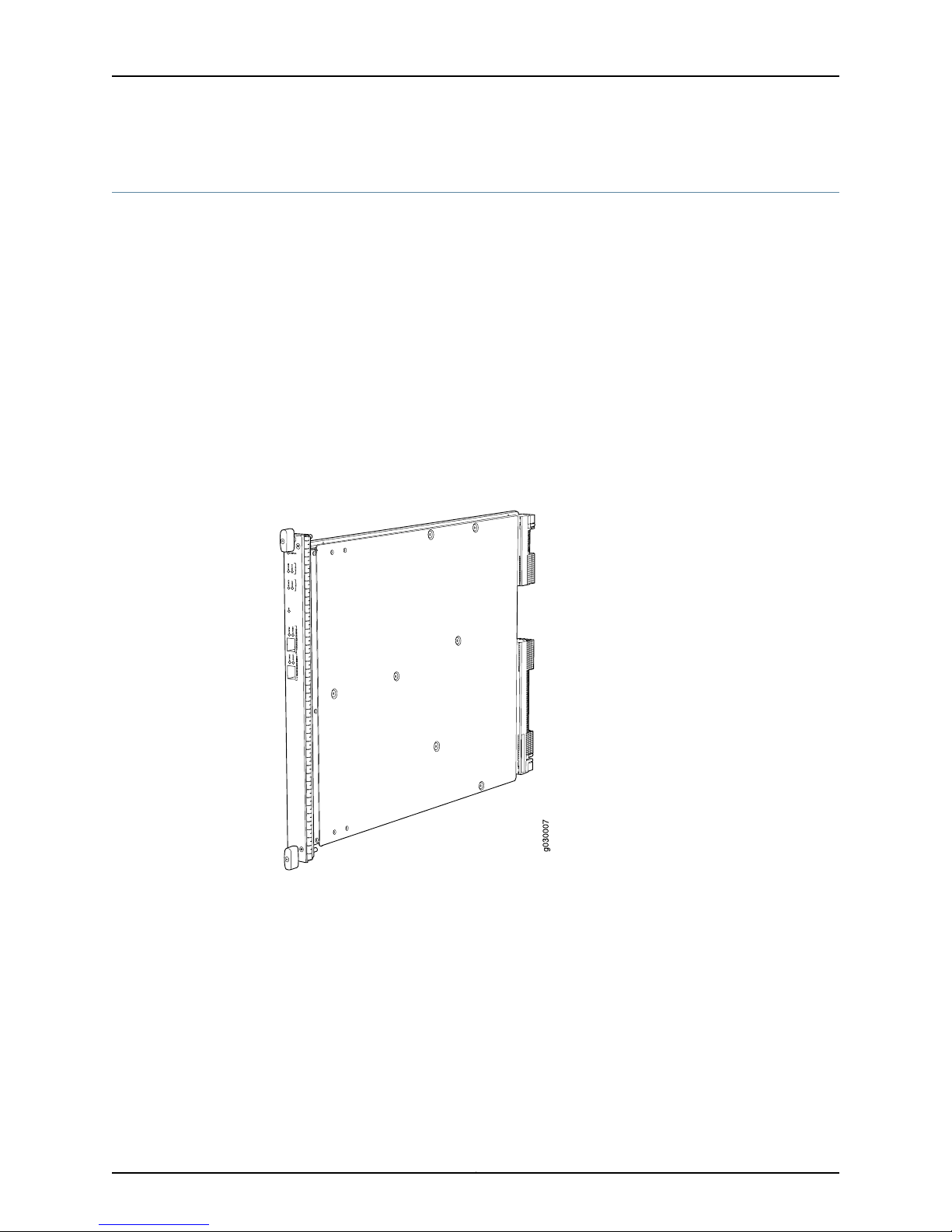
Figure 1 on page 4 shows a typical SPC supported on the services gateway.
Figure 1: Services Processing Card SRX5K-SPC-2-10-40
Each SPC consists of the following components:
•
SPC cover, which functions as a ground plane and a stiffener.
•
Two small form-factor pluggable (SFP) chassis cluster control ports for connecting
multiple devices into a redundant chassis cluster. See Junos OS Security Configuration
Guide for more information about connecting and configuring redundant chassis
clusters.
Copyright © 2013, Juniper Networks, Inc.4

Services Processing Card SRX5K-SPC-2-10-40
NOTE: We strongly recommend the use of Juniper Networks SFP
transceivers. We cannot guarantee correct operation if other transceivers
are used. The transceiver type can be different in each port, as long as a
supported part number is used.
•
Fabric interfaces.
•
Two Gigabit Ethernet interfaces that allow control information, route information, and
statistics to be sent between the Routing Engine and the CPU on the SPCs.
•
Two interfaces from the SCBs that enable the boards to be powered on and controlled.
•
Physical SPC connectors.
•
Midplane connectors and power circuitry.
•
Processor subsystem, which includes a 1.2-GHz CPU, system controller, and 1 GB of
SDRAM.
•
LEDs on the faceplate that indicate the SPC and SPU status.
Cables and
connectors
Supported Slots
SPC with two SPUsDescription
•
Junos OS Release 9.2 and laterSoftware release
CHASSIS CLUSTER CONTROL 0 and CHASSIS CLUSTER CONTROL 1–SFP ports for control links in
chassis cluster configurations.
NoneControls
•
SRX5600–Any slot except bottom slots 0 or 1
•
SRX5800–Any slot except center slots 0, 1, or 2/6
Maximum 351 WPower Requirement
Approximately 13 lb (5.9 kg)Weight
5Copyright © 2013, Juniper Networks, Inc.

SRX5600 and SRX5800 Services Gateway Card Guide
LEDs
OK/FAIL LED, one bicolor:
•
Steady green–The SPC is operating normally.
•
Red–The SPC has failed and is not operating normally.
•
Off–The SPC is powered down.
STATUS LED, one tricolor for each of the two SPUs SPU 0 and SPU 1:
•
Green–The SPU is operating normally.
•
Amber–The SPU is initializing.
•
Red–The SPU has encountered an error or a failure.
•
Off–The SPU is offline. If all four SPUs are offline, it is safe to remove the SPC from the chassis.
SERVICE LED, one bicolor for each of the two SPUs, SPU 0 and SPU 1:
•
Green–Service is running on the SPU under acceptable load.
•
Amber–Service on the SPU is overloaded.
•
Off–Service is not running on the SPU.
HA LED, one tricolor:
•
Green–Clustering is operating normally. All cluster members and monitored links are available, and
no error conditions are detected.
•
Red–A critical alarm is present on clustering. A cluster member is missing or unreachable, or the
other node is no longer part of a cluster because it has been disabled by the dual membership and
detection recovery process in reaction to a control link or fabric link failure.
•
Amber–All cluster members are present, but an error condition has compromised the performance
and resiliency of the cluster. The reduced bandwidth could cause packets to be dropped or could
result in reduced resiliency because a single point of failure might exist. The error condition might
be caused by:
•
The loss of chassis cluster links which causes an interface monitoring failure.
•
An error in an SPU or NPU.
•
Failure of the spu-monitoring or cold-sync-monitoring processes.
•
A chassis cluster IP monitoring failure.
LINK/ACT LED, one for each of the two ports CHASSIS CLUSTER CONTROL 0 and CHASSIS CLUSTER
CONTROL 1:
•
Green–Chassis cluster control port link is active.
•
Off–No link.
ENABLE LED, one for each of the two ports CHASSIS CLUSTER CONTROL 0 and CHASSIS CLUSTER
CONTROL 1:
•
Green–The chassis cluster control port is enabled.
•
Off–The chassis cluster control port is disabled.
Copyright © 2013, Juniper Networks, Inc.6
OK/
F
AIL
TUNNEL
LINK
1/0
TUNNEL
LINK
0/0
TUNNEL
LINK
2/0
TUNNEL
LINK
3/0
g004067
AA567 8
Serial number
ID label
Services Processing Card SRX5K-SPC-2-10-40
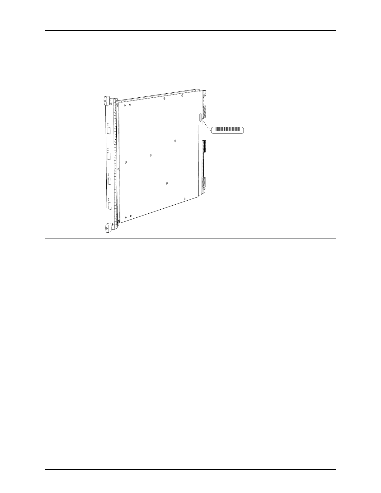
Serial Number
Location
The serial number label is located as shown in Figure 2 on page 7.
Figure 2: Serial Number Label (IOC Shown, Other Cards Similar)
7Copyright © 2013, Juniper Networks, Inc.
g030302
SRX5600 and SRX5800 Services Gateway Card Guide
Services Processing Card SRX5K-SPC-4-15-320
The SRX5K-SPC-4-15-320 Services Processing Card (SPC) contains four Services
Processing Units (SPUs), which provide the processing power to run integrated services
such as firewall, IPsec, and IDP (see Figure 3 on page 8). All traffic traversing the services
gateway is passed to an SPU to have services processing applied to it. Traffic is
intelligently distributed by I/O cards (IOCs) to SPUs for services processing.
The services gateway must have at least one SPC installed. You can install additional
SPCs to increase services processing capacity.
You can install SPCs in any of the slots that are not reserved for Switch Control Boards
(SCBs). If a slot is not occupied by a card, you must install a blank panel to shield the
empty slot and to allow cooling air to circulate properly through the device.
If your services gateway contains a mix of SRX5K-SPC-4-15-320 SPCs and earlier
SRX5K-SPC-2-10-40 SPCs, an SRX5K-SPC-4-15-320 SPC must occupy the
lowest-numbered slot of any SPC in the chassis. This configuration ensures that the
center point (CP) function is performed by the faster and higher-performance SPC type.
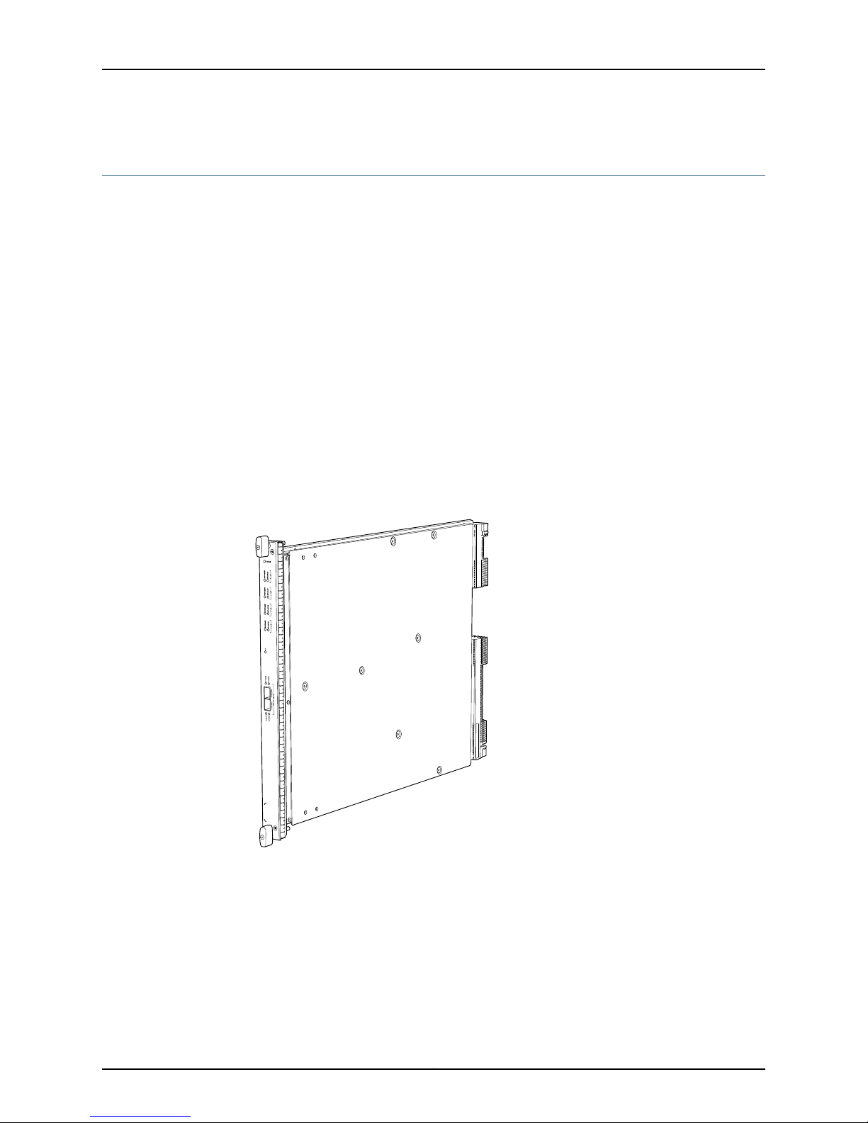
Figure 3: Services Processing Card SRX5K-SPC-4-15-320
Each SPC consists of the following components:
•
SPC cover, which functions as a ground plane and a stiffener.
•
Two small form-factor pluggable (SFP) chassis cluster control ports for connecting
multiple devices into a redundant chassis cluster. See Junos OS Security Configuration
Guide for more information about connecting and configuring redundant chassis
clusters.
Copyright © 2013, Juniper Networks, Inc.8

Services Processing Card SRX5K-SPC-4-15-320
NOTE: We strongly recommend the use of Juniper Networks SFP
transceivers. We cannot guarantee correct operation if other transceivers
are used. The transceiver type can be different in each port, as long as a
supported part number is used.
•
Fabric interfaces.
•
Two Gigabit Ethernet interfaces that allow control information, route information, and
statistics to be sent between the Routing Engine and the CPU on the SPCs.
•
Two interfaces from the SCBs that enable the boards to be powered on and controlled.
•
Physical SPC connectors.
•
Midplane connectors and power circuitry.
•
Processor subsystem, which includes a 1.2-GHz CPU, system controller, and 1 GB of
SDRAM.
•
LEDs on the faceplate that indicate the SPC and SPU status.
Cables and
connectors
Supported Slots
Power
Requirement
SPC with four SPUsDescription
•
Junos OS Release 12.1X44-D10 and laterSoftware release
CHASSIS CLUSTER CONTROL 0 and CHASSIS CLUSTER CONTROL 1–SFP ports for control links in chassis
cluster configurations.
NoneControls
•
SRX5600–Any slot except bottom slots 0 or 1
•
SRX5800–Any slot except center slots 0 or 1
450 W typical, 585 W maximum
NOTE:
•
You must have high-capacity power supplies (either AC or DC) and high-capacity fan trays installed
in the services gateway in order to install and use SRX5K-SPC-4-15-320 SPCs. If you do not have
high-capacity power supplies and fan trays installed, the services gateway will log an alarm condition
when it recognizes the SRX5K-SPC-4-15-320 SPCs.
•
On SRX5600 Services Gateways with AC power supplies, we recommend that you use high-line (220v)
input power to ensure the device has adequate power to support SRX5K-SPC-4-15-320 SPCs.
Approximately 18 lb (8.3 kg)Weight
9Copyright © 2013, Juniper Networks, Inc.

SRX5600 and SRX5800 Services Gateway Card Guide
LEDs
OK/FAIL LED, one bicolor:
•
Steady green–The SPC is operating normally.
•
Red–The SPC has failed and is not operating normally.
•
Off–The SPC is powered down.
STATUS LED, one tricolor for each of the four SPUs SPU 0 through SPU 3:
•
Green–The SPU is operating normally.
•
Amber–The SPU is initializing.
•
Red–The SPU has encountered an error or a failure.
•
Off–The SPU is offline. If all four SPUs are offline, it is safe to remove the SPC from the chassis.
SERVICE LED, one bicolor for each of the four SPUs SPU 0 through SPU 3:
•
Green–Service is running on the SPU under acceptable load.
•
Amber–Service on the SPU is overloaded.
•
Off–Service is not running on the SPU.
HA LED, one tricolor:
•
Green–Clustering is operating normally. All cluster members and monitored links are available, and no
error conditions are detected.
•
Red–A critical alarm is present on clustering. A cluster member is missing or unreachable, or the other
node is no longer part of a cluster because it has been disabled by the dual membership and detection
recovery process in reaction to a control-link or fabric-link failure.
•
Amber–All cluster members are present, but an error condition has compromised the performance
and resiliency of the cluster. The reduced bandwidth could cause packets to be dropped or could result
in reduced resiliency because a single point of failure might exist. The error condition might be caused
by:
•
The loss of chassis cluster links which causes an interface monitoring failure.
•
An error in an SPU or NPU.
•
Failure of the spu-monitoring or cold-sync-monitoring processes.
•
A chassis cluster IP monitoring failure.
•
Off–The node is not configured for clustering or it has been disabled by the dual membership and
detection recovery process in reaction to a control link or fabric link failure.
LINK/ACT LED, one for each of the two ports CHASSIS CLUSTER CONTROL 0 and CHASSIS CLUSTER
CONTROL 1:
•
Green–Chassis cluster control port link is active.
•
Off–No link.
ENABLE LED, one for each of the two ports CHASSIS CLUSTER CONTROL 0 and CHASSIS CLUSTER
CONTROL 1:
•
Green–The chassis cluster control port is enabled.
•
Off–The chassis cluster control port is disabled.
Copyright © 2013, Juniper Networks, Inc.10
OK/
F
AIL
TUNNEL
LINK
1/0
TUNNEL
LINK
0/0
TUNNEL
LINK
2/0
TUNNEL
LINK
3/0
g004067
AA567 8
Serial number
ID label
Services Processing Card SRX5K-SPC-4-15-320
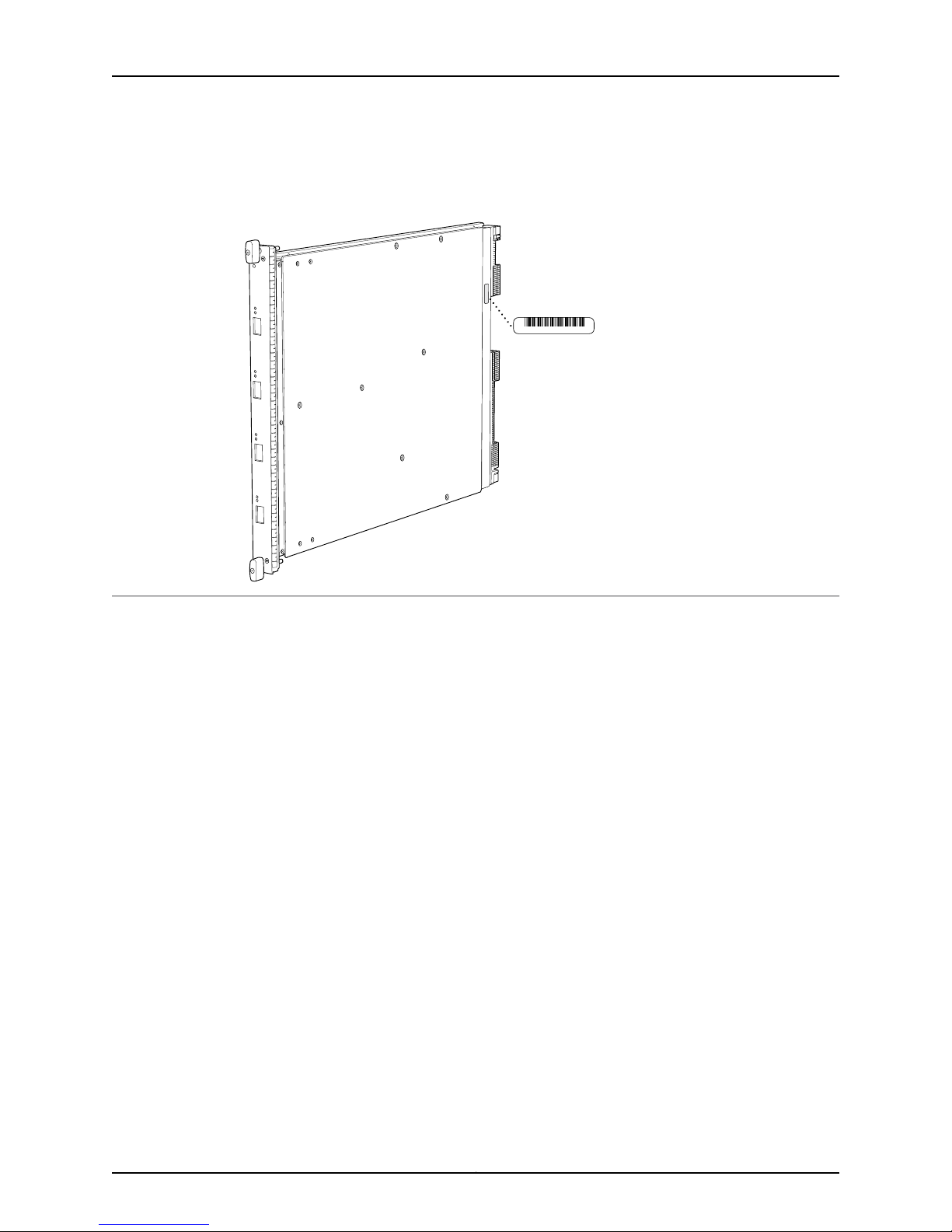
Serial Number
Location
Documentation
The serial number label is located as shown in Figure 4 on page 11.
Figure 4: Serial Number Label (IOC Shown, Other Cards Similar)
Related
Cards Supported on SRX5600 and SRX5800 Services Gateways on page 2•
11Copyright © 2013, Juniper Networks, Inc.
 Loading...