

Page 1

SRX5600 Services Gateway Hardware
Published
2020-12-07
Guide
Page 2

Juniper Networks, Inc.
1133 Innovation Way
Sunnyvale, California 94089
USA
408-745-2000
www.juniper.net
Juniper Networks, the Juniper Networks logo, Juniper, and Junos are registered trademarks of Juniper Networks, Inc. in
the United States and other countries. All other trademarks, service marks, registered marks, or registered service marks
are the property of their respective owners.
Juniper Networks assumes no responsibility for any inaccuracies in this document. Juniper Networks reserves the right
to change, modify, transfer, or otherwise revise this publication without notice.
SRX5600 Services Gateway Hardware Guide
Copyright © 2020 Juniper Networks, Inc. All rights reserved.
The information in this document is current as of the date on the title page.
ii
YEAR 2000 NOTICE
Juniper Networks hardware and software products are Year 2000 compliant. Junos OS has no known time-related
limitations through the year 2038. However, the NTP application is known to have some difficulty in the year 2036.
END USER LICENSE AGREEMENT
The Juniper Networks product that is the subject of this technical documentation consists of (or is intended for use with)
Juniper Networks software. Use of such software is subject to the terms and conditions of the End User License Agreement
(“EULA”) posted at https://support.juniper.net/support/eula/. By downloading, installing or using such software, you
agree to the terms and conditions of that EULA.
Page 3

Table of Contents
1
About the Documentation | xv
Documentation and Release Notes | xv
Using the Examples in This Manual | xv
Merging a Full Example | xvi
Merging a Snippet | xvii
Documentation Conventions | xvii
Documentation Feedback | xx
Requesting Technical Support | xx
Self-Help Online Tools and Resources | xxi
Creating a Service Request with JTAC | xxi
iii
Overview
SRX5600 Services Gateway System Overview | 23
SRX5600 Services Gateway Description | 23
Benefits of the SRX5600 Services Gateway | 24
SRX5600 Services Gateway FRUs | 24
SRX5600 Services Gateway Component Redundancy | 25
SRX5600 Chassis | 26
SRX5600 Services Gateway Chassis | 27
SRX5600 Services Gateway Physical Specifications | 29
SRX5600 Services Gateway Midplane Description | 30
SRX5600 Services Gateway Cable Manager Description | 31
SRX5600 Services Gateway Craft Interface Overview | 32
SRX5600 Services Gateway Craft Interface Alarm LEDs and Alarm Cutoff/Lamp Test
Button | 33
SRX5600 Services Gateway Craft Interface Host Subsystem LEDs | 34
SRX5600 Services Gateway Craft Interface Power Supply LEDs | 35
SRX5600 Services Gateway Craft Interface Card OK/Fail LEDs | 35
SRX5600 Services Gateway Craft Interface Fan LEDs | 35
SRX5600 Services Gateway Craft Interface Online Buttons | 36
Page 4

SRX5600 Services Gateway Craft Interface Alarm Relay Contacts | 39
SRX5600 Services Gateway Cooling System Description | 40
SRX3400 and SRX5600 Services Gateways Air Deflector Kits | 43
SRX5600 Power System | 45
SRX5600 Services Gateway Power System Overview | 45
SRX5600 Services Gateway AC Power Supply | 47
SRX5600 Services Gateway AC Power Supply Specifications | 49
SRX5600 Services Gateway AC Power Supply LEDs | 49
AC Power Cord Specifications for the SRX5600 Services Gateway | 50
AC Power Circuit Breaker Requirements for the SRX5600 Services Gateway | 53
SRX5600 Services Gateway DC Power Supply | 53
SRX5600 Services Gateway DC Power Supply Specifications | 54
SRX5600 Services Gateway DC Power Supply LEDs | 55
iv
DC Power Cable Specifications for the SRX5600 Services Gateway | 56
DC Power Cable Lug Specifications for the SRX5600 Services Gateway | 57
DC Power Circuit Breaker Requirements for the SRX5600 Services Gateway | 57
DC Power Source Cabling for the SRX5600 Services Gateway | 58
SRX5600 Services Gateway Chassis Grounding Point Specifications | 59
SRX5600 Services Gateway Grounding-Cable Lug Specification | 60
SRX5600 Host Subsystem | 61
SRX5600 Services Gateway Host Subsystem Description | 61
Switch Control Board SRX5K-SCB Overview | 62
Switch Control Board SRX5K-SCB Specifications | 63
Switch Control Board SRX5K-SCBE Overview | 66
Switch Control Board SRX5K-SCBE Specifications | 67
SRX5K-SCBE LEDs | 69
Switch Control Board SRX5K-SCB3 Overview | 70
Switch Control Board SRX5K-SCB3 Specifications | 71
SRX5K-SCB3 LEDs | 72
Switch Control Board SRX5K-SCB4 Overview | 73
Switch Control Board SRX5K-SCB4 Specifications | 74
SRX5K-SCB4 LEDs | 76
Page 5

Routing Engine SRX5K-RE-1800X4 Overview | 77
SRX5K-RE-1800X4 Routing Engine Boot Sequence | 78
Routing Engine SRX5K-RE-1800X4 Specifications | 78
SRX5K-RE-1800X4 LEDs | 80
Routing Engine SRX5K-RE-13-20 Overview | 81
Routing Engine SRX5K-RE-13-20 Specifications | 82
Routing Engine SRX5K-RE3-128G Specifications | 85
SRX5K-RE3-128G Routing Engine Components | 87
SRX5K-RE3-128G Routing Engine LEDs | 88
SRX5K-RE3-128G Routing Engine Boot Sequence | 89
SRX5600 Line Cards and Modules | 89
SRX5400, SRX5600, and SRX5800 Services Gateway Card Overview | 90
SRX5600 Services Gateway Card Terminology | 91
v
Cards Supported on SRX5400, SRX5600, and SRX5800 Services Gateways | 92
SRX5600 Services Gateway Card Cage and Slots | 96
SRX5600 Services Gateway SPC Description | 96
Services Processing Card SRX5K-SPC-2-10-40 Specifications | 97
Services Processing Card SRX5K-SPC-4-15-320 Specifications | 102
Services Processing Card SRX5K-SPC3 Specifications | 107
SRX5600 Services Gateway Interface Card Description | 111
Modular Port Concentrator (SRX5K-MPC) Specifications | 113
SRX5K-MPC3-40G10G Specifications | 116
SRX5K-MPC3-100G10G Specifications | 119
MIC with 20x1GE SFP Interfaces (SRX-MIC-20GE-SFP) | 122
MIC with 10x10GE SFP+ Interfaces (SRX-MIC-10XG-SFPP) | 128
MIC with 1x100GE CFP Interface (SRX-MIC-1X100G-CFP) | 133
MIC with 2x40GE QSFP+ Interfaces (SRX-MIC-2X40G-QSFP) | 135
SRX5K-IOC4-10G Specifications | 136
SRX5K-IOC4-MRAT Specifications | 139
I/O Card SRX5K-40GE-SFP Specifications | 143
I/O Card SRX5K-4XGE-XFP Specifications | 145
Flex I/O Card (SRX5K-FPC-IOC) Specifications | 147
Flex I/O Card Port Module SRX-IOC-16GE-SFP Specifications | 149
Flex I/O Card Port Module SRX-IOC-16GE-TX Specifications | 151
Page 6

Flex I/O Card Port Module SRX-IOC-4XGE-XFP Specifications | 152
2
Site Planning, Preparation, and Specifications
Site Preparation Checklist for the SRX5600 Services Gateway | 156
SRX5600 Site Guidelines and Requirements | 157
SRX5600 Services Gateway Environmental Specifications | 157
General Site Guidelines | 158
Site Electrical Wiring Guidelines | 159
Clearance Requirements for SRX5600 Services Gateway Airflow and Hardware
Maintenance | 160
SRX5600 Rack and Cabinet Requirements | 161
SRX5600 Services Gateway Rack Size and Strength Requirements | 161
Spacing of Rack Mounting Bracket Holes for the SRX5600 Services Gateway | 162
Connection to Building Structure for the SRX5600 Services Gateway Rack | 162
vi
SRX5600 Services Gateway Cabinet Size and Clearance Requirements | 162
SRX5600 Services Gateway Cabinet Airflow Requirements | 163
Calculating Power Requirements for the SRX5600 Services Gateway | 163
SRX5600 Network Cable and Transceiver Planning | 175
Routing Engine Interface Cable and Wire Specifications for the SRX5600 Services Gateway | 175
Signal Loss in Multimode and Single-Mode Fiber-Optic Cable for the SRX5600 Services
Gateway | 176
Attenuation and Dispersion in Fiber-Optic Cable for the SRX5600 Services Gateway | 176
Calculating Power Budget for Fiber-Optic Cable for the SRX5600 Services Gateway | 177
Calculating Power Margin for Fiber-Optic Cable for the SRX5600 Services Gateway | 178
SRX5600 Alarm and Management Cable Specifications and Pinouts | 179
Alarm Relay Contact Wire Specifications for the SRX5600 Services Gateway | 180
Console Port Cable and Wire Specifications for the SRX5600 Services Gateway | 180
RJ-45 Connector Pinouts for the SRX5600 Services Gateway Routing Engine Ethernet Port | 180
RJ-45 Connector Pinouts for the SRX5600 Services Gateway Routing Engine Auxiliary and
Console Ports | 181
Page 7

Initial Installation and Configuration
3
Overview of Installing the SRX5600 Services Gateway | 184
Unpacking the SRX5600 | 185
Tools and Parts Required to Unpack the SRX5600 Services Gateway | 185
Unpacking the SRX5600 Services Gateway | 185
Verifying the SRX5600 Services Gateway Parts Received | 187
Installing the SRX5600 Mounting Hardware | 189
Installing the SRX5600 Services Gateway Mounting Hardware for a Rack or Cabinet | 189
Moving the Mounting Brackets for Center-Mounting the SRX5600 Services Gateway | 192
Installing the SRX5600 Using a Mechanical Lift | 193
Tools Required to Install the SRX5600 Services Gateway with a Mechanical Lift | 193
Installing the SRX5600 Services Gateway Using a Mechanical Lift | 194
vii
Installing the SRX5600 Without a Mechanical Lift | 196
Overview of Installing the SRX5600 Services Gateway Without a Mechanical Lift | 196
Tools Required to Install the SRX5600 Services Gateway Without a Mechanical Lift | 197
Removing Components from the SRX5600 Chassis Before Installing It Without a Lift | 197
Removing the Power Supplies Before Installing the SRX5600 Services Gateway Without
a Lift | 197
Removing the Fan Tray Before Installing an SRX5600 Services Gateway Without a Lift | 198
Removing Cards Before Installing an SRX5600 Services Gateway Without a Lift | 199
Installing the SRX5600 Services Gateway Chassis in the Rack Manually | 202
Reinstalling Components in the SRX5600 Services Gateway Chassis After Installing It Without
a Lift | 204
Reinstalling Power Supplies After Installing the SRX5600 Services Gateway Without a
Lift | 204
Reinstalling the Fan Tray After Installing the SRX5600 Services Gateway Without a Lift | 205
Reinstalling SCBs After Installing the SRX5600 Services Gateway Without a Lift | 206
Reinstalling IOCs, Flex IOCs, and SPCs After Installing the SRX5600 Services Gateway
Without a Lift | 207
Page 8

Connecting the SRX5600 to External Devices | 208
4
Tools and Parts Required for SRX5600 Services Gateway Connections | 208
Connecting the SRX5600 Services Gateway to a Management Console or an Auxiliary
Device | 209
Connecting the SRX5600 Services Gateway to a Network for Out-of-Band Management | 210
Connecting an SRX5600 Services Gateway to an External Alarm-Reporting Device | 211
Connecting Network Cables to SRX5600 Services Gateway IOCs and Port Modules | 212
Connecting the SRX5600 to Power | 214
Tools and Parts Required for SRX5600 Services Gateway Grounding and Power
Connections | 214
Grounding the SRX5600 Services Gateway | 215
Connecting Power to an AC-Powered SRX5600 Services Gateway | 216
Powering On an AC-Powered SRX5600 Services Gateway | 218
Connecting Power to a DC-Powered SRX5600 Services Gateway | 219
viii
Powering On a DC-Powered SRX5600 Services Gateway | 221
Powering Off the SRX5600 Services Gateway | 223
Performing the Initial Software Configuration for the SRX5600 | 224
SRX5600 Services Gateway Software Configuration Overview | 224
Initially Configuring the SRX5600 Services Gateway | 225
Performing Initial Software Configuration Using J-Web | 230
Configuring Root Authentication and the Management Interface from the CLI | 230
Configuring Interfaces, Zones, and Policies with J-Web | 232
Maintaining Components
Maintaining the SRX5600 Chassis | 237
Routine Maintenance Procedures for the SRX5600 Services Gateway | 237
Replacing the SRX5600 Services Gateway Craft Interface | 237
Disconnecting the Alarm Relay Wires from the SRX5600 Services Gateway Craft
Interface | 237
Removing the SRX5600 Services Gateway Craft Interface | 238
Installing the SRX5600 Services Gateway Craft Interface | 239
Page 9

Connecting the Alarm Relay Wires to the SRX5600 Services Gateway Craft Interface | 240
Maintaining the SRX5600 Cooling System | 241
Maintaining the Fan Tray on the SRX5600 Services Gateway | 241
Replacing the SRX5600 Services Gateway Fan Tray | 242
Removing the SRX5600 Services Gateway Fan Tray | 242
Installing the SRX5600 Services Gateway Fan Tray | 243
Maintaining the Air Filter on the SRX5600 Services Gateway | 244
Replacing the SRX5600 Services Gateway Air Filter | 245
Removing the SRX5600 Services Gateway Air Filter | 245
Installing the SRX5600 Services Gateway Air Filter | 246
Maintaining the SRX5600 Power System | 247
Maintaining SRX5600 Services Gateway Power Supplies | 247
Replacing an SRX5600 Services Gateway AC Power Supply | 248
ix
Removing an SRX5600 Services Gateway AC Power Supply | 249
Installing an SRX5600 Services Gateway AC Power Supply | 250
Replacing an SRX5600 Services Gateway AC Power Supply Cord | 251
Disconnecting an SRX5600 Services Gateway AC Power Supply Cord | 252
Connecting an SRX5600 Services Gateway AC Power Supply Cord | 252
Replacing an SRX5600 Services Gateway DC Power Supply | 253
Removing an SRX5600 Services Gateway DC Power Supply | 253
Installing an SRX5600 Services Gateway DC Power Supply | 254
Replacing an SRX5600 Services Gateway DC Power Supply Cable | 257
Disconnecting an SRX5600 Services Gateway DC Power Supply Cable | 257
Connecting an SRX5600 Services Gateway DC Power Supply Cable | 258
Upgrading an SRX5600 Services Gateway from Standard-Capacity to High-Capacity Power
Supplies | 259
Page 10

Maintaining the SRX5600 Host Subsystem | 263
Maintaining the SRX5600 Services Gateway Host Subsystem and SCBs | 263
Taking the SRX5600 Services Gateway Host Subsystem Offline | 265
Operating and Positioning the SRX5600 Services Gateway SCB Ejectors | 266
Replacing an SRX5600 Services Gateway SCB | 266
Removing an SRX5600 Services Gateway SCB | 267
Installing an SRX5600 Services Gateway SCB | 268
Replacing the SRX5600 Services Gateway Routing Engine | 270
Removing the SRX5600 Services Gateway Routing Engine | 270
Installing the SRX5600 Services Gateway Routing Engine | 271
Low Impact Hardware Upgrade for SCB3 and IOC3 | 274
In-Service Hardware Upgrade for SRX5K-RE-1800X4 and SRX5K-SCBE or SRX5K-RE-1800X4
and SRX5K-SCB3 in a Chassis Cluster | 292
Maintaining the SRX5600 Line Cards and Modules | 296
x
Maintaining Interface Cards and SPCs on the SRX5600 Services Gateway | 297
Holding an SRX5600 Services Gateway Card | 299
Storing an SRX5600 Services Gateway Card | 301
Replacing SRX5600 Services Gateway IOCs | 302
Removing an SRX5600 Services Gateway IOC | 302
Installing an SRX5600 Services Gateway IOC | 304
Replacing SRX5600 Services Gateway Flex IOCs | 307
Removing an SRX5600 Services Gateway Flex IOC | 307
Installing an SRX5600 Services Gateway Flex IOC | 310
Replacing SRX5600 Services Gateway SPCs | 312
Removing an SRX5600 Services Gateway SPC | 312
Installing an SRX5600 Services Gateway SPC | 314
Replacing SPCs in an Operating SRX5400, SRX5600, or SRX5800 Services Gateways Chassis
Cluster | 317
In-Service Hardware Upgrade for SRX5K-SPC3 in a Chassis Cluster | 320
Maintaining MICs and Port Modules on the SRX5600 Services Gateway | 323
Replacing SRX5600 Services Gateway MICs | 324
Removing an SRX5600 Services Gateway MIC | 324
Installing an SRX5600 Services Gateway MIC | 326
Page 11

Replacing SRX5600 Services Gateway Port Modules | 328
5
Removing an SRX5600 Services Gateway Port Module | 328
Installing an SRX5600 Services Gateway Port Module | 330
Replacing SRX5600 Services Gateway MPCs | 332
Removing an SRX5600 Services Gateway MPC | 333
Installing an SRX5600 Services Gateway MPC | 335
Maintaining the SRX5600 Cables and Connectors | 337
Maintaining SRX5600 Services Gateway Network Cables | 337
Replacing the Management Ethernet Cable on the SRX5600 Services Gateway | 339
Replacing the SRX5600 Services Gateway Console or Auxiliary Cable | 340
Replacing an SRX5600 Services Gateway Network Interface Cable | 341
Removing an SRX5600 Services Gateway Network Interface Cable | 341
Installing an SRX5600 Services Gateway Network Interface Cable | 343
xi
Replacing SRX5600 Services Gateway XFP and SFP Transceivers | 345
Removing an SRX5600 Services Gateway SFP or XFP Transceiver | 345
Installing an SRX5600 Services Gateway SFP or XFP Transceiver | 347
Replacing the SRX5600 Services Gateway Cable Manager | 348
Removing the SRX5600 Services Gateway Cable Manager | 348
Installing the SRX5600 Services Gateway Cable Manager | 349
Replacing a Routing Engine in an SRX Series High-End Chassis Cluster | 350
Replacing a Routing Engine: USB Flash-Drive Method | 350
Replacing a Routing Engine: External SCP Server Method | 357
Replacing the Routing Engine: File Transfer Method | 364
Troubleshooting Hardware
Troubleshooting the SRX5600 | 371
Troubleshooting the SRX5600 Services Gateway with the Junos OS CLI | 371
Troubleshooting the SRX5600 Services Gateway with Chassis and Interface Alarm
Messages | 372
Chassis Component Alarm Conditions on SRX5400, SRX5600, and SRX5800 Services
Gateways | 372
Backup Routing Engine Alarms | 387
Troubleshooting the SRX5600 Services Gateway with Alarm Relay Contacts | 389
Troubleshooting the SRX5600 Services Gateway with the Craft Interface LEDs | 389
Page 12

Troubleshooting the SRX5600 Services Gateway with the Component LEDs | 390
6
7
Troubleshooting the SRX5600 Services Gateway Cooling System | 391
Troubleshooting SRX5600 Services Gateway Interface Cards | 391
Troubleshooting SRX5600 Services Gateway MICs and Port Modules | 393
Troubleshooting SRX5600 Services Gateway SPCs | 394
Troubleshooting the SRX5600 Services Gateway Power System | 395
Behavior of the SRX5400, SRX5600, and SRX5800 Services Gateways When the SRX5K-SCBE
and SRX5K-RE-1800X4 in a Chassis Cluster Fail | 401
Contacting Customer Support and Returning the Chassis or Components
Returning the SRX5600 Chassis or Components | 404
Contacting Customer Support | 404
Return Procedure for the SRX5600 Services Gateway | 405
Listing the SRX5600 Services Gateway Component Serial Numbers with the CLI | 406
xii
Locating the SRX5600 Services Gateway Chassis Serial Number Label | 407
Locating the SRX5600 Services Gateway Power Supply Serial Number Labels | 407
Locating the SRX5600 Services Gateway Craft Interface Serial Number Label | 408
Information You Might Need to Supply to JTAC | 409
Required Tools and Parts for Packing the SRX5600 Services Gateway | 409
Packing the SRX5600 Services Gateway for Shipment | 410
Packing SRX5600 Services Gateway Components for Shipment | 411
Safety and Compliance Information
General Safety Guidelines and Warnings | 414
Definitions of Safety Warning Levels | 415
Restricted Access Area Warning | 419
Fire Safety Requirements | 421
Fire Suppression | 421
Fire Suppression Equipment | 422
Qualified Personnel Warning | 423
Warning Statement for Norway and Sweden | 423
Installation Instructions Warning | 424
Page 13

Chassis and Component Lifting Guidelines | 424
Ramp Warning | 425
Rack-Mounting and Cabinet-Mounting Warnings | 425
Grounded Equipment Warning | 431
Laser and LED Safety Guidelines and Warnings | 432
General Laser Safety Guidelines | 432
Class 1 Laser Product Warning | 433
Class 1 LED Product Warning | 434
Laser Beam Warning | 435
Radiation from Open Port Apertures Warning | 436
Maintenance and Operational Safety Guidelines and Warnings | 437
xiii
Battery Handling Warning | 438
Jewelry Removal Warning | 439
Lightning Activity Warning | 441
Operating Temperature Warning | 442
Product Disposal Warning | 444
General Electrical Safety Guidelines and Warnings | 445
Prevention of Electrostatic Discharge Damage | 446
AC Power Electrical Safety Guidelines | 447
AC Power Disconnection Warning | 449
DC Power Electrical Safety Guidelines | 450
DC Power Electrical Safety Guidelines | 450
DC Power Disconnection Warning | 452
DC Power Grounding Requirements and Warning | 454
DC Power Wiring Sequence Warning | 456
DC Power Wiring Terminations Warning | 459
DC Power Disconnection Warning | 462
DC Power Grounding Requirements and Warning | 464
DC Power Wiring Sequence Warning | 466
Page 14

DC Power Wiring Terminations Warning | 469
Multiple Power Supplies Disconnection Warning | 472
TN Power Warning | 473
Action to Take After an Electrical Accident | 473
SRX5600 Services Gateway Agency Approvals | 474
SRX5600 Services Gateway Compliance Statements for EMC Requirements | 475
Canada | 475
European Community | 475
Israel | 476
Japan | 476
United States | 476
xiv
Statements of Volatility for Juniper Network Devices | 477
Page 15
About the Documentation
IN THIS SECTION
Documentation and Release Notes | xv
Using the Examples in This Manual | xv
Documentation Conventions | xvii
Documentation Feedback | xx
Requesting Technical Support | xx
Use this guide to install hardware and perform initial software configuration, routine maintenance, and
troubleshooting for the SRX5600 Services Gateway.
xv
After completing the installation and basic configuration procedures covered in this guide, refer to the
Junos OS documentation for information about further software configuration.
Documentation and Release Notes
To obtain the most current version of all Juniper Networks®technical documentation, see the product
documentation page on the Juniper Networks website at https://www.juniper.net/documentation/.
If the information in the latest release notes differs from the information in the documentation, follow the
product Release Notes.
Juniper Networks Books publishes books by Juniper Networks engineers and subject matter experts.
These books go beyond the technical documentation to explore the nuances of network architecture,
deployment, and administration. The current list can be viewed at https://www.juniper.net/books.
Using the Examples in This Manual
If you want to use the examples in this manual, you can use the load merge or the load merge relative
command. These commands cause the software to merge the incoming configuration into the current
candidate configuration. The example does not become active until you commit the candidate configuration.
Page 16

If the example configuration contains the top level of the hierarchy (or multiple hierarchies), the example
is a full example. In this case, use the load merge command.
If the example configuration does not start at the top level of the hierarchy, the example is a snippet. In
this case, use the load merge relative command. These procedures are described in the following sections.
Merging a Full Example
To merge a full example, follow these steps:
1. From the HTML or PDF version of the manual, copy a configuration example into a text file, save the
file with a name, and copy the file to a directory on your routing platform.
For example, copy the following configuration to a file and name the file ex-script.conf. Copy the
ex-script.conf file to the /var/tmp directory on your routing platform.
system {
scripts {
commit {
file ex-script.xsl;
}
}
}
interfaces {
fxp0 {
disable;
unit 0 {
family inet {
address 10.0.0.1/24;
}
}
}
}
xvi
2. Merge the contents of the file into your routing platform configuration by issuing the load merge
configuration mode command:
[edit]
user@host# load merge /var/tmp/ex-script.conf
load complete
Page 17

Merging a Snippet
To merge a snippet, follow these steps:
1. From the HTML or PDF version of the manual, copy a configuration snippet into a text file, save the
file with a name, and copy the file to a directory on your routing platform.
For example, copy the following snippet to a file and name the file ex-script-snippet.conf. Copy the
ex-script-snippet.conf file to the /var/tmp directory on your routing platform.
commit {
file ex-script-snippet.xsl; }
2. Move to the hierarchy level that is relevant for this snippet by issuing the following configuration mode
command:
[edit]
user@host# edit system scripts
[edit system scripts]
xvii
3. Merge the contents of the file into your routing platform configuration by issuing the load merge
relative configuration mode command:
[edit system scripts]
user@host# load merge relative /var/tmp/ex-script-snippet.conf
load complete
For more information about the load command, see CLI Explorer.
Documentation Conventions
Table 1 on page xviii defines notice icons used in this guide.
Page 18
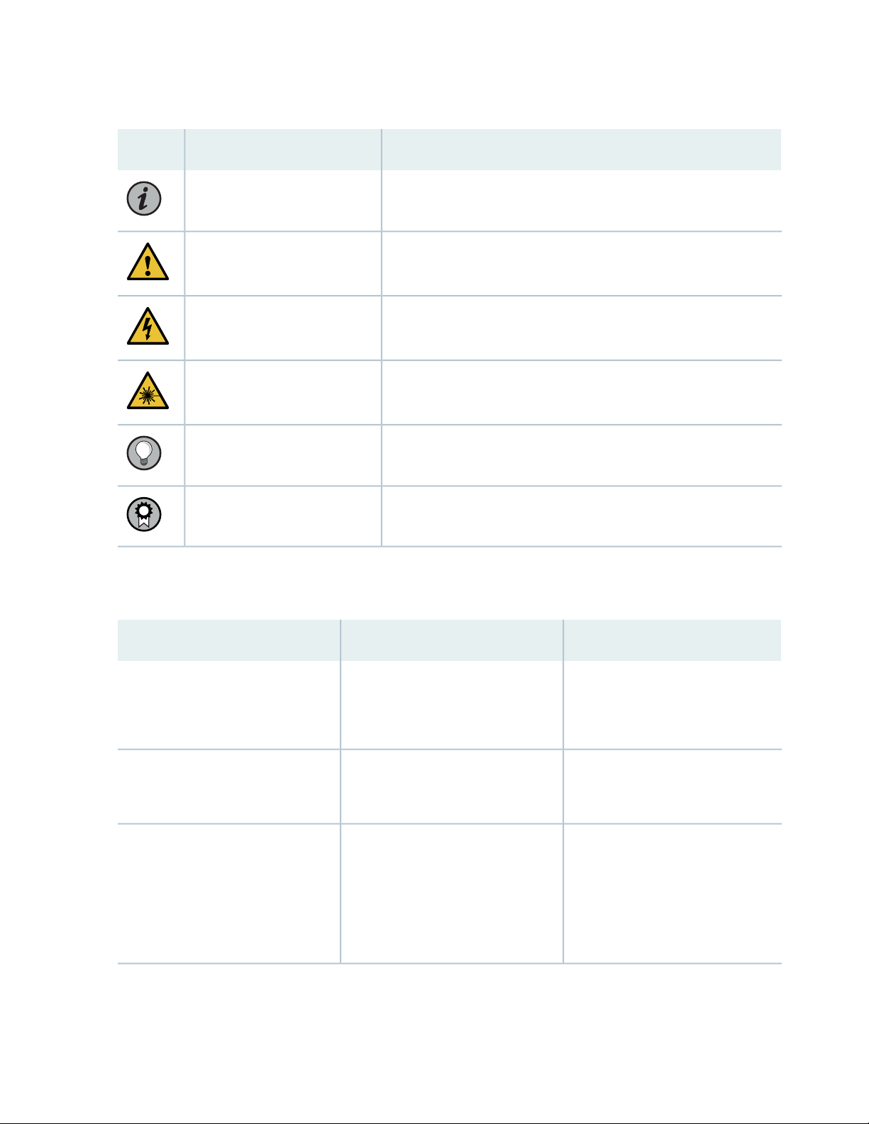
Table 1: Notice Icons
xviii
DescriptionMeaningIcon
Indicates important features or instructions.Informational note
Caution
Indicates a situation that might result in loss of data or hardware
damage.
Alerts you to the risk of personal injury or death.Warning
Alerts you to the risk of personal injury from a laser.Laser warning
Indicates helpful information.Tip
Alerts you to a recommended use or implementation.Best practice
Table 2 on page xviii defines the text and syntax conventions used in this guide.
Table 2: Text and Syntax Conventions
ExamplesDescriptionConvention
Fixed-width text like this
Italic text like this
Represents text that you type.Bold text like this
Represents output that appears on
the terminal screen.
Introduces or emphasizes important
•
new terms.
Identifies guide names.
•
Identifies RFC and Internet draft
•
titles.
To enter configuration mode, type
the configure command:
user@host> configure
user@host> show chassis alarms
No alarms currently active
A policy term is a named structure
•
that defines match conditions and
actions.
Junos OS CLI User Guide
•
RFC 1997, BGP Communities
•
Attribute
Page 19

Table 2: Text and Syntax Conventions (continued)
xix
ExamplesDescriptionConvention
Italic text like this
Text like this
< > (angle brackets)
| (pipe symbol)
Represents variables (options for
which you substitute a value) in
commands or configuration
statements.
Represents names of configuration
statements, commands, files, and
directories; configuration hierarchy
levels; or labels on routing platform
components.
variables.
Indicates a choice between the
mutually exclusive keywords or
variables on either side of the symbol.
The set of choices is often enclosed
in parentheses for clarity.
Configure the machine’s domain
name:
[edit]
root@# set system domain-name
domain-name
To configure a stub area, include
•
the stub statement at the [edit
protocols ospf area area-id]
hierarchy level.
The console port is labeled
•
CONSOLE.
stub <default-metric metric>;Encloses optional keywords or
broadcast | multicast
(string1 | string2 | string3)
# (pound sign)
[ ] (square brackets)
Indention and braces ( { } )
; (semicolon)
GUI Conventions
Indicates a comment specified on the
same line as the configuration
statement to which it applies.
Encloses a variable for which you can
substitute one or more values.
Identifies a level in the configuration
hierarchy.
Identifies a leaf statement at a
configuration hierarchy level.
rsvp { # Required for dynamic MPLS
only
community name members [
community-ids ]
[edit]
routing-options {
static {
route default {
nexthop address;
retain;
}
}
}
Page 20
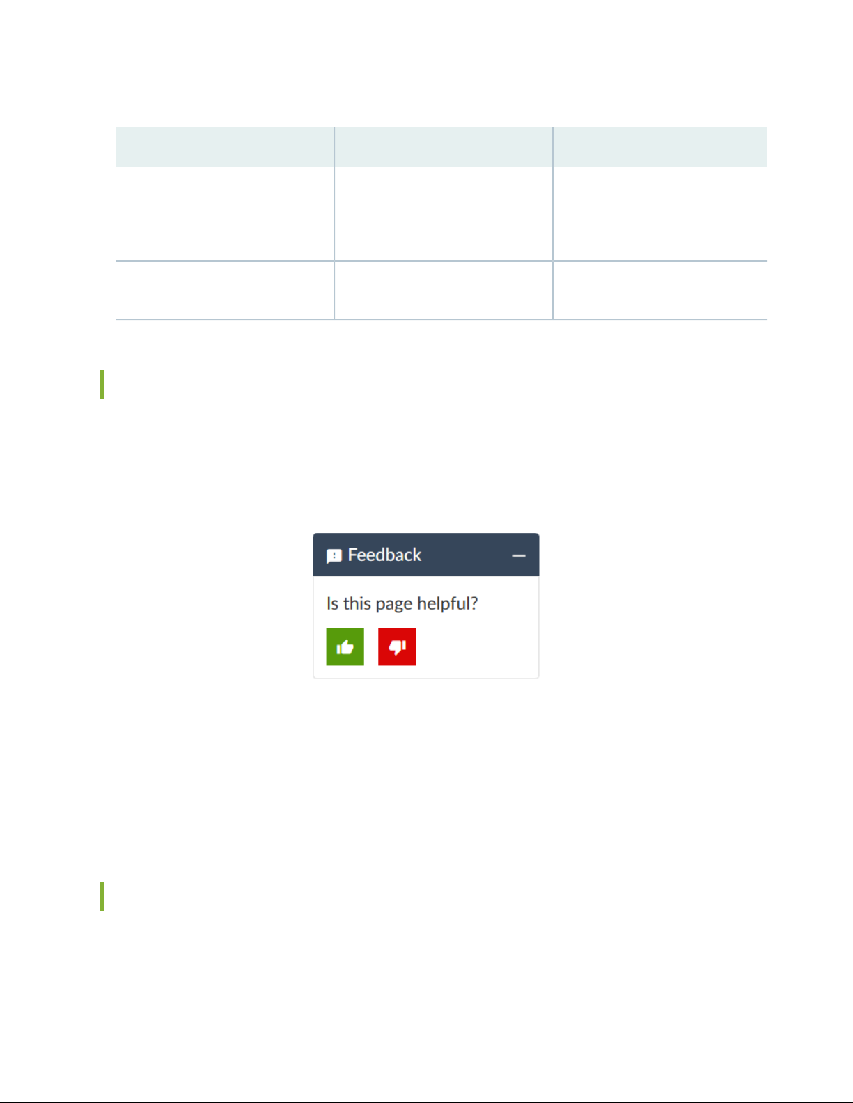
Table 2: Text and Syntax Conventions (continued)
xx
ExamplesDescriptionConvention
Bold text like this
> (bold right angle bracket)
Represents graphical user interface
(GUI) items you click or select.
Separates levels in a hierarchy of
menu selections.
In the Logical Interfaces box, select
•
All Interfaces.
To cancel the configuration, click
•
Cancel.
In the configuration editor hierarchy,
select Protocols>Ospf.
Documentation Feedback
We encourage you to provide feedback so that we can improve our documentation. You can use either
of the following methods:
Online feedback system—Click TechLibrary Feedback, on the lower right of any page on the Juniper
•
Networks TechLibrary site, and do one of the following:
Click the thumbs-up icon if the information on the page was helpful to you.
•
Click the thumbs-down icon if the information on the page was not helpful to you or if you have
•
suggestions for improvement, and use the pop-up form to provide feedback.
E-mail—Send your comments to techpubs-comments@juniper.net. Include the document or topic name,
•
URL or page number, and software version (if applicable).
Requesting Technical Support
Technical product support is available through the Juniper Networks Technical Assistance Center (JTAC).
If you are a customer with an active Juniper Care or Partner Support Services support contract, or are
Page 21

covered under warranty, and need post-sales technical support, you can access our tools and resources
online or open a case with JTAC.
JTAC policies—For a complete understanding of our JTAC procedures and policies, review the JTAC User
•
Guide located at https://www.juniper.net/us/en/local/pdf/resource-guides/7100059-en.pdf.
Product warranties—For product warranty information, visit https://www.juniper.net/support/warranty/.
•
JTAC hours of operation—The JTAC centers have resources available 24 hours a day, 7 days a week,
•
365 days a year.
Self-Help Online Tools and Resources
For quick and easy problem resolution, Juniper Networks has designed an online self-service portal called
the Customer Support Center (CSC) that provides you with the following features:
Find CSC offerings: https://www.juniper.net/customers/support/
•
Search for known bugs: https://prsearch.juniper.net/
•
xxi
Find product documentation: https://www.juniper.net/documentation/
•
Find solutions and answer questions using our Knowledge Base: https://kb.juniper.net/
•
Download the latest versions of software and review release notes:
•
https://www.juniper.net/customers/csc/software/
Search technical bulletins for relevant hardware and software notifications:
•
https://kb.juniper.net/InfoCenter/
Join and participate in the Juniper Networks Community Forum:
•
https://www.juniper.net/company/communities/
Create a service request online: https://myjuniper.juniper.net
•
To verify service entitlement by product serial number, use our Serial Number Entitlement (SNE) Tool:
https://entitlementsearch.juniper.net/entitlementsearch/
Creating a Service Request with JTAC
You can create a service request with JTAC on the Web or by telephone.
Visit https://myjuniper.juniper.net.
•
Call 1-888-314-JTAC (1-888-314-5822 toll-free in the USA, Canada, and Mexico).
•
For international or direct-dial options in countries without toll-free numbers, see
https://support.juniper.net/support/requesting-support/.
Page 22

1
CHAPTER
Overview
SRX5600 Services Gateway System Overview | 23
SRX5600 Chassis | 26
SRX5600 Services Gateway Cooling System Description | 40
SRX3400 and SRX5600 Services Gateways Air Deflector Kits | 43
SRX5600 Power System | 45
SRX5600 Host Subsystem | 61
SRX5600 Line Cards and Modules | 89
Page 23
SRX5600 Services Gateway System Overview
IN THIS SECTION
SRX5600 Services Gateway Description | 23
Benefits of the SRX5600 Services Gateway | 24
SRX5600 Services Gateway FRUs | 24
SRX5600 Services Gateway Component Redundancy | 25
SRX5600 Services Gateway Description
23
The SRX5600 Services Gateway is a high-performance, highly scalable, carrier-class security device with
multi-processor architecture.
The SRX5600 Services Gateway is 8 rack units (U) tall. Three of these devices can be stacked in a single
floor-to-ceiling rack, for increased port density per unit of floor space.
The services gateway provides eight slots that you can populate with two Switch Control Boards (SCBs)
and six other cards of the following types:
Services Processing Cards (SPCs) provide the processing capacity to run integrated services such as
•
firewall, IPsec, and IDP.
Modular PIC Concentrators (MPCs) provide Ethernet interfaces that connect the services gateway to
•
your network.
I/O cards (IOCs) provide Ethernet interfaces that connect the services gateway to your network.
•
Flex IOCs are similar to IOCs, but have slots for port modules that allow you greater flexibility in adding
•
different types of Ethernet ports to your services gateway.
For detailed information about the cards supported by the services gateway, see the SRX5400, SRX5600,
and SRX5800 Services Gateway Card Reference at www.juniper.net/documentation/.
Page 24

Benefits of the SRX5600 Services Gateway
The next generation SPCs and IOCs on the SRX5600 Services Gateway support up to 570 IMIX Gbps
•
firewall throughput, 180 million concurrent sessions, and 460 Gbps IPS.
The ability to support unique security policies per zone and ability to scale with the growth of the network
infrastructure, makes the SRX5600 an ideal deployment for consolidation of services in large enterprise,
service provider, or mobile operator environments.
IPS Capabilities - Juniper Networks IPS capabilities offer several unique features such as Protocol decodes,
•
Zero-day protection, Active/active traffic monitoring, and packet capture logging per rule assure the
highest level of network security.
Content Security UTM Capabilities - The UTM services offered on the SRX5000 line of Services Gateways
•
include industry-leading antivirus, antispam, content filtering, and additional content security services.
The UTM services provide sophisticated protection from:
Antivirus experts against malware attacks that can lead to data breaches and lost productivity.
•
Advanced persistent threats perpetrated through social networking attacks and the latest phishing
•
scams with sophisticated e-mail filtering and content blockers.
24
Lost productivity and the impact of malicious URLs and extraneous or malicious content on the network
•
to help maintain bandwidth.
Advanced Threat Prevention (ATP) - Juniper Sky ATP, a SaaS-based service, and the Juniper ATP
•
Appliance, an on-premises solution:
Protects enterprise users from a spectrum of advanced malware that exploits “zero-day” vulnerabilities.
•
Proactively blocks malware communication channels.
•
The Juniper ATP Appliance includes support for cloud-based e-mail services such as Office 365 and
•
Google Mail, and detects threats in SMB traffic.
Single pane-of-glass management with Security Director and JSA Series integration.
•
SRX5600 Services Gateway FRUs
Field-replaceable units (FRUs) are services gateway components that can be replaced at the customer site.
The services gateway uses the following types of FRUs:
Table 3 on page 25 lists the FRUs of the services gateway and the action to perform to install, remove, or
replace an FRU.
Page 25

Table 3: Field-Replaceable Units
25
ActionField-Replaceable Units (FRUs)
Air filter
Fan tray
Craft interface
AC and DC power supplies (if redundant)
SFP and XFP transceivers
IOCs
Flex IOCs
Port modules of the Flex IOCs
Routing Engine
SCBs
SPCs
You need not power off the services gateway to install, remove, or
replace any of these FRUs.
Power off the services gateway to install, remove, or replace any of
these FRUs.
MPCs
MICs
SRX5600 Services Gateway Component Redundancy
The following major hardware components are redundant:
SCBs—The host subsystem consists of a Routing Engine installed in an SCB. The device must have one
•
host subsystem installed. You can install a second SCB for redundancy. If a second SCB is installed, the
host subsystem SCB functions as the primary and the other functions as the backup. If the SCB of the
host subsystem fails, the other SCB takes over as the primary.
Power supplies—In the low-line (110 V) AC power configuration, the device contains three or four AC
•
power supplies, located horizontally at the rear of the chassis in slots PEM0 through PEM3 (left to right).
Each AC power supply provides power to all components in the device. When three power supplies are
present, they share power almost equally within a fully populated system. Four AC power supplies
Page 26
provide full power redundancy. If one power supply fails or is removed, the remaining power supplies
instantly assume the entire electrical load without interruption. Three power supplies provide the
maximum configuration with full power for as long as the device is operational.
In the high-line (220 V) AC power configuration, the device contains two or four AC power supplies
located horizontally at the rear of the chassis in slots PEM0 through PEM3 (left to right). Each AC power
supply provides power to all components in the device. When two or more power supplies are present,
they share power almost equally within a fully populated system. Four AC power supplies provide full
power redundancy. If one power supply fails or is removed, the remaining power supplies instantly
assume the entire electrical load without interruption. Two power supplies provide the maximum
configuration with full power for as long as the device is operational.
In the DC configuration, two power supplies are required to supply power to a fully configured device.
One power supply supports approximately half of the components in the device, and the other power
supply supports the remaining components. The addition of two power supplies provides full power
redundancy. If one power supply fails or is removed, the remaining power supplies instantly assume the
entire electrical load without interruption. Two power supplies provide the maximum configuration with
full power for as long as the device is operational.
26
Cooling system—The cooling system has redundant components, which are controlled by the host
•
subsystem. If one of the fans fails, the host subsystem increases the speed of the remaining fans to
provide sufficient cooling for the services gateway indefinitely.
SRX5600 Chassis
IN THIS SECTION
SRX5600 Services Gateway Chassis | 27
SRX5600 Services Gateway Physical Specifications | 29
SRX5600 Services Gateway Midplane Description | 30
SRX5600 Services Gateway Cable Manager Description | 31
SRX5600 Services Gateway Craft Interface Overview | 32
SRX5600 Services Gateway Craft Interface Alarm LEDs and Alarm Cutoff/Lamp Test Button | 33
SRX5600 Services Gateway Craft Interface Host Subsystem LEDs | 34
SRX5600 Services Gateway Craft Interface Power Supply LEDs | 35
SRX5600 Services Gateway Craft Interface Card OK/Fail LEDs | 35
SRX5600 Services Gateway Craft Interface Fan LEDs | 35
Page 27
SRX5600 Services Gateway Craft Interface Online Buttons | 36
SRX5600 Services Gateway Craft Interface Alarm Relay Contacts | 39
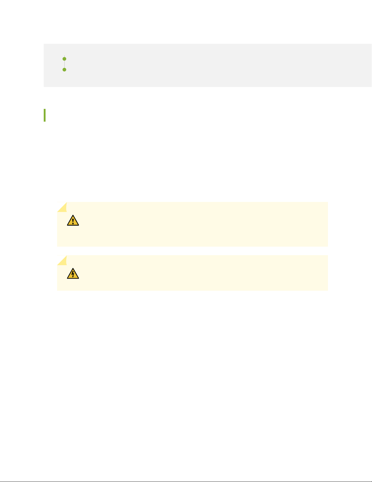
SRX5600 Services Gateway Chassis
The services gateway chassis is a rigid sheet metal structure that houses all the other components (see
Figure 1 on page 28, Figure 2 on page 28, and Figure 3 on page 29). The chassis measures 14.0 in. (35.6 cm)
high, 17.45 in. (44.3 cm) wide, and 24.5 in. (62.2 cm) deep (from the front to the rear of the chassis). The
chassis installs in standard 800-mm (or larger) enclosed cabinets, 19-in. equipment racks, or telco open-frame
racks. Up to five services gateways can be installed in one standard (48 U) rack if the rack can handle their
combined weight, which can be greater than 1100 lb (500 kg). See “SRX5600 Services Gateway Physical
Specifications” on page 29 for physical specifications for the SRX5600 Services Gateway.
27
CAUTION: Before removing or installing components of a services gateway, attach
an ESD strap to an ESD point and place the other end of the strap around your bare
wrist. Failure to use an ESD strap can result in damage to the services gateway.
WARNING: The services gateway must be connected to earth ground during normal
operation.
Page 28
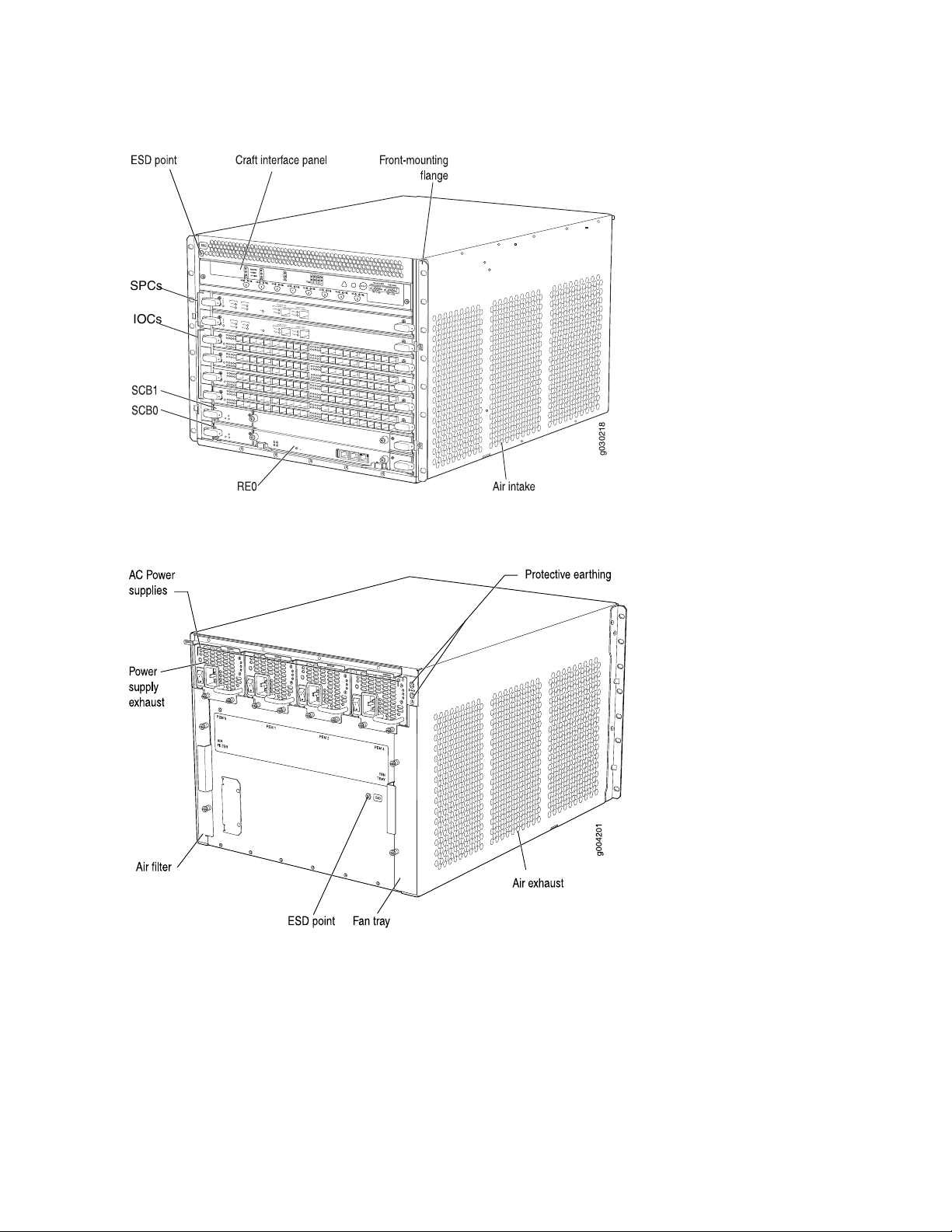
Figure 1: Front View of a Fully Configured Services Gateway Chassis
STATUS
SPU0
SERVICE
STATUS
SPU1
SERVICE
HA
OK/FAIL
CHASSISCLUSTER
CONTROL0
ENABLE
LINK/ACT
CHASSISCLUSTER
CONTROL1
ENABLE
LINK/ACT
STATUS
SPU0
SERVICE
STATUS
SPU1
SERVICE
HA
OK/FAIL
CHASSISCLUSTER
CONTROL0
ENABLE
LINK/ACT
CHASSISCLUSTER
CONTROL1
ENABLE
LINK/ACT
SPCs
g030218
IOCs
28
Figure 2: Rear View of a Fully Configured AC-Powered Services Gateway Chassis
Page 29
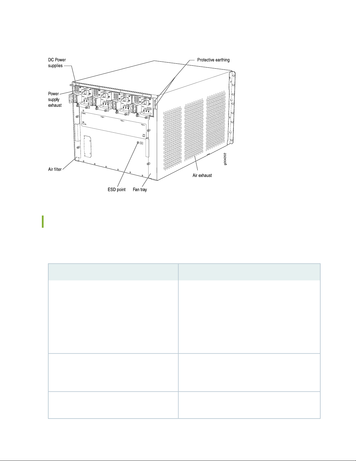
Figure 3: Rear View of a Fully Configured DC-Powered Services Gateway Chassis
29
SRX5600 Services Gateway Physical Specifications
Table 4 on page 29 summarizes the physical specifications for the services gateway chassis.
Table 4: Physical Specifications
ValueDescription
Chassis dimensions
Services Gateway weight
14.0 in. (35.6 cm) high
17.45 in. (44.3 cm) wide
24.5 in. (62.2 cm) deep (from front-mounting bracket to
chassis rear)
Total depth (including cable management system):
27.75 in. (70.5 cm)
Chassis with midplane, fan tray, air filter, and cable
management system: 65.5 lb (29.7 kg)
Maximum configuration: 220 lb (100 kg)
Routing Engine weight
SRX5K-RE-13-20: 2.4 lb (1.1 kg)
SRX5K-RE-1800X4: 2.4 lb (1.1 kg)
Page 30

Table 4: Physical Specifications (continued)
30
ValueDescription
SCB weight
supported on devices with SRX5K-SCB and
SRX5K-RE-13-20)
SRX5K-SCB: 9.6 lb (4.4 kg)
SRX5K-SCBE: 9.6 lb (4.4 kg)
SRX5K-SCB3: 10.14 lb (4.6 kg)
13.1 lb (5.9 kg)MPC weight (with two MICs)
13.1 lb (5.9 kg)IOC weight
1.1 lb (0.5 kg)Craft interface weight
4.2 lb (1.9 kg)Fan tray weight
1.0 lb (0.5 kg)Air filter weight
0.3 lb (0.14 kg)Cable management weight
3.8 lb (1.7 kg)Standard-capacity DC power supply weight (only
6.2 lb (2.8 kg)High-capacity DC power supply weight
5.0 lb (2.3 kg)Standard-capacity AC power supply weight (only
supported on devices with SRX5K-SCB and
SRX5K-RE-13-20)
6.6 lb (3.0 kg)High-capacity AC power supply weight
SRX5600 Services Gateway Midplane Description
The midplane is located toward the rear of the chassis and forms the rear of the card cage (see
Figure 4 on page 31). IOCs, Flex IOCs, SPCs, and SCBs install into the midplane from the front of the
chassis, and the power supplies install into the midplane from the rear of the chassis. The cooling system
components also connect to the midplane.
Page 31

The midplane performs the following major functions:
Data path—Data packets are transferred across the midplane between the IOCs and SPCs through the
•
fabric ASICs on the SCBs.
Power distribution—The power supplies are connected to the midplane, which distributes power to all
•
the services gateway components.
Signal path—The midplane provides the signal path to the IOCs, SCBs, SPCs, Routing Engine, and other
•
system components for monitoring and control of the system.
The enhanced midplane supports Junos OS Release15.1X49-D10. It provides greater per-slot fabric
performance and signal integrity, along with error-free high speed data transfer, and it reduces cross-talk.
The midplane supports link speeds up to 10 Gbps and is not field replaceable.
Figure 4: Midplane
31
SRX5600 Services Gateway Cable Manager Description
The cable management system (see Figure 5 on page 32 and Figure 6 on page 32) consists of plastic
dividers located on the left and right sides of each IOC slot. The cable management system allows you to
route the cables outside the services gateway and away from the IOCs.
Page 32
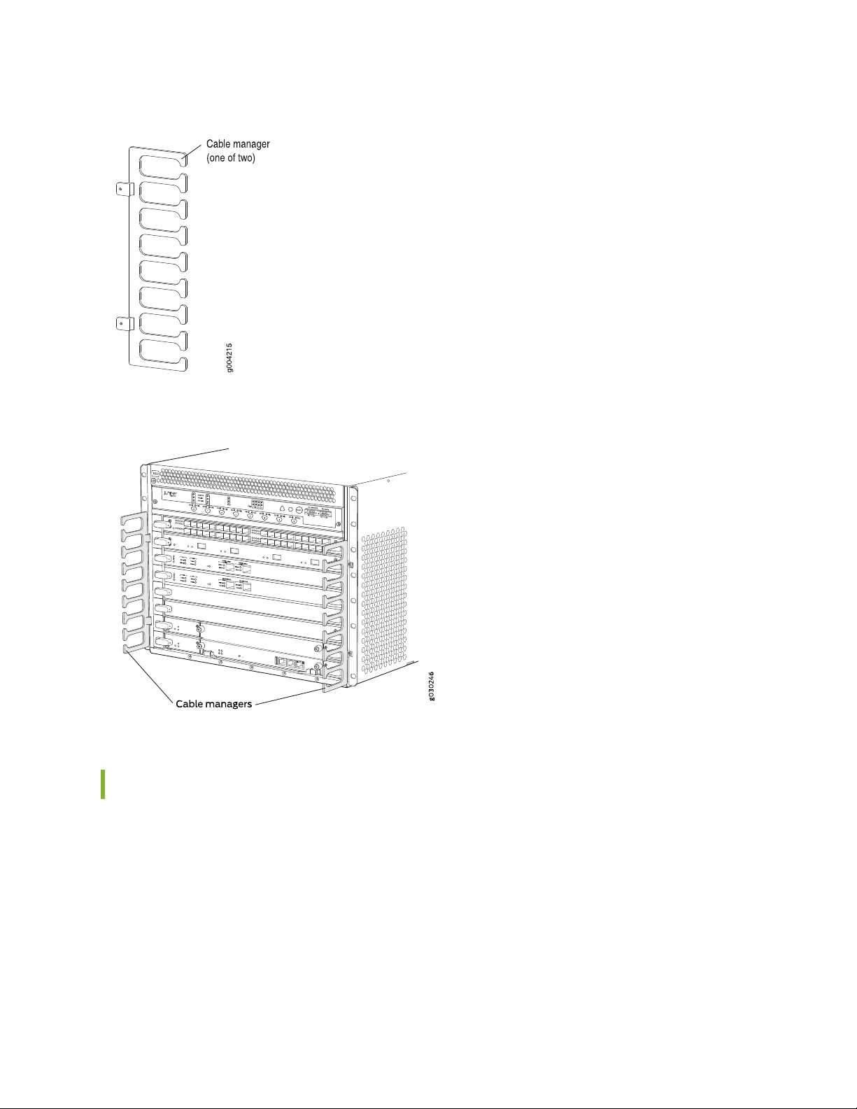
Figure 5: Cable Manager
Figure 6: Cable Management System Installed on the Device
32
SRX5600 Services Gateway Craft Interface Overview
The craft interface shows you status and troubleshooting information at a glance and lets you perform
many system control functions. It is hot-insertable and hot-removable. The craft interface is located on
the front of the services gateway above the upper fan tray. See Figure 7 on page 33.
Page 33
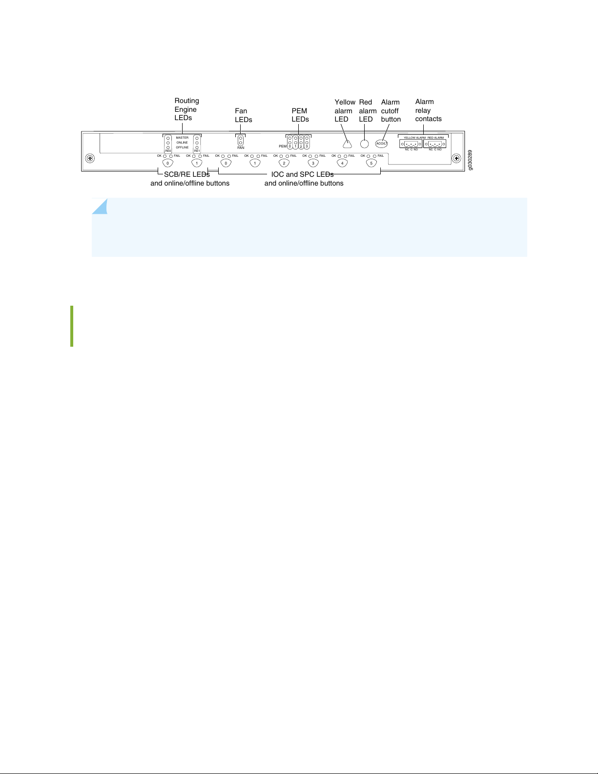
Figure 7: Front Panel of the Craft Interface
0
OK FAIL1OK FAIL0OK FAIL1OK FAIL2OK FAIL3OK FAIL4OK FAIL5OK FAIL
ACO/LT
RE0 RE1
YELLOW ALARM RED ALARM
NC NOC NC NOC
Alarm
relay
contacts
Yellow
alarm
LED
Red
alarm
LED
Alarm
cutoff
button
IOC and SPC LEDs
and online/offline buttons
SCB/RE LEDs
and online/offline buttons
g030289
PEM
FAN
0 1
2
3
MASTER
ONLINE
OFFLINE
PEM
LEDs
Fan
LEDs
Routing
Engine
LEDs
NOTE: At least one SCB must be installed in the services gateway for the craft interface to
obtain power.
SRX5600 Services Gateway Craft Interface Alarm LEDs and Alarm
33
Cutoff/Lamp Test Button
Two large alarm LEDs are located at the upper right of the craft interface. The circular red LED lights to
indicate a critical condition that can result in a system shutdown. The triangular yellow LED lights to indicate
a less severe condition that requires monitoring or maintenance. Both LEDs can be lit simultaneously. A
condition that causes an LED to light also activates the corresponding alarm relay contact on the craft
interface.
To deactivate the red and yellow alarms, press the button labeled ACO/LT (for “alarm cutoff/lamp test”),
which is located to the right of the alarm LEDs. Deactivating an alarm turns off both LEDs and deactivates
the device attached to the corresponding alarm relay contact on the craft interface.
Table 5 on page 34 describes the alarm LEDs and alarm cutoff button in more detail.
Page 34
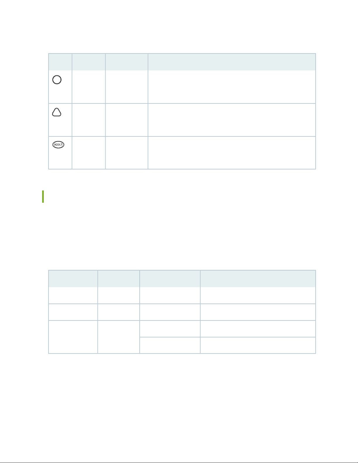
Table 5: Alarm LEDs and Alarm Cutoff/Lamp Test Button
DescriptionStateColorShape
34
On steadilyRed
On steadilyYellow
––
Critical alarm LED—Indicates a critical condition that can cause the
device to stop functioning. Possible causes include component removal,
failure, or overheating.
Warning alarm LED—Indicates a serious but nonfatal error condition,
such as a maintenance alert or a significant increase in component
temperature.
Alarm cutoff/lamp test button—Deactivates red and yellow alarms.
Causes all LEDs on the craft interface to light (for testing) when pressed
and held.
SRX5600 Services Gateway Craft Interface Host Subsystem LEDs
The host subsystem has three LEDs, located in the middle of the craft interface, that indicate its status.
The LEDs labeled RE0 show the status of the Routing Engine and SCB in slot 0 .
The LEDs labeled RE1 show the status of the Routing Engine and SCB in slot 1. Table 6 on page 34 describes
the functions of the host subsystem LEDs.
Table 6: Host Subsystem LEDs
DescriptionStateColorLabel
Host is functioning as the master.On steadilyGreenMASTER
Host is online and is functioning normally.On steadilyGreenONLINE
Host is installed but the Routing Engine is offline.On steadilyRedOFFLINE
Host is not installed.Off
Page 35
SRX5600 Services Gateway Craft Interface Power Supply LEDs
Each power supply has two LEDs on the craft interface that indicate its status. The LEDs, labeled 0 through
3, are located near the middle of the craft interface next to the PEM label. Table 7 on page 35 describes
the functions of the power supply LEDs on the craft interface.
Table 7: Power Supply LEDs on the Craft Interface
DescriptionStateColorLabel
Power supply is functioning normally.On steadilyGreenPEM
Power supply has failed or power input has failed.On steadilyRed
SRX5600 Services Gateway Craft Interface Card OK/Fail LEDs
35
Each slot in the card cage has a pair of LEDs on the craft interface that indicates the status of the card
installed in it. The card LEDs are located along the bottom edge of the craft interface and are labeled 0
and 1 for the slots reserved for SCBs and 0 through 5 for the remaining slots.
Table 8 on page 35 describes the functions of the OK and Fail LEDs.
Table 8: Card OK/Fail LEDs
DescriptionStateColorLabel
The card is functioning normally.On steadilyGreenOK
The card is transitioning online or offline.Blinking
The card is not online.Off
The card has failed.On steadilyRedFAIL
SRX5600 Services Gateway Craft Interface Fan LEDs
Each fan LED is located on the top left of the craft interface. Table 9 on page 36 describes the functions
of the fan LEDs.
Page 36
Table 9: Fan LEDs
DescriptionStateColorLabel
Fan tray is functioning normally.On steadilyGreenOK
Fan tray has failed.On steadilyRedFAIL
SRX5600 Services Gateway Craft Interface Online Buttons
The craft interface has a row of Online/Offline buttons along its lower edge. Each button corresponds to
one slot in the card cage. The Online/Offline buttons are only supported for slots containing MPC interface
cards. You can install MPCs into slots:
SRX5400–Any slot except bottom slot 0
•
36
SRX5600–Any slot except bottom slots 0 or 1
•
SRX5800–Any slot except center slots 0 or 1
•
NOTE: The Online/Offline buttons are not supported for removal and replacement of SPCs or
SCB.
CAUTION: While traffic is passing through the Services Gateway, particularly if the
device is configured as part of a high availability (HA) cluster, we strongly recommend
that you do not push any of the Online/Offline buttons.
To take an MPC offline using the Online/Offline buttons:
1. Press and hold the corresponding card’s Online/Offline button on slot 1 on the craft interface. The
green OK/FAIL LED next to the button begins to blink. Hold until both the button’s LED and the MPC’s
LED are off.
2. Issue the CLI show chassis fpc command to check the status of installed MPCs. As shown in the sample
output, the value Offline in the column labeled State indicates that the MPC in slot 1 is now offline:
user@host> show chassis fpc
Page 37

Slot State (C) Total Interrupt DRAM (MB) Heap Buffer
0 Online 35 4 0 1024 13 25
1 Online 47 3 0 1024 13 25
2 Online 37 8 0 2048 18 14
An MPC can also be taken offline via CLI command:
user@host> request chassis fpc slot 2 offline
node0:
-------------------------------------------------------------------------Offline initiated, use "show chassis fpc" to verify
{primary:node0}
user@host> show chassis fpc
37
node0:
------------------------------------------------------------------------- Temp CPU Utilization (%) Memory Utilization (%)
Slot State (C) Total Interrupt DRAM (MB) Heap Buffer
0 Online 35 7 0 1024 13 25
1 Online 46 4 0 1024 13 25
2 Offline ---Offlined by cli command---
After pushing MPC online button:
user@host> show chassis fpc
Temp CPU Utilization (%) Memory Utilization (%)
Slot State (C) Total Interrupt DRAM (MB) Heap Buffer
0 Online 34 5 0 1024 13 25
1 Online 46 3 0 1024 13 25
2 Offline ---Offlined by button press---
To bring an MPC back online using the Online/Offline buttons:
1. Press and hold the corresponding card’s Online/Offline button on slot 1 on the craft interface. The
green OK/FAIL LED next to the button and the MPC’s LED begins to blink. Hold until both the button’s
LED and the MPC’s LED are green and steady.
Page 38

2. Issue the CLI show chassis fpc command to check the status of installed MPCs. As shown in the sample
output, the value Online in the column labeled State indicates that the MPC in slot 1 is functioning
normally:
Verify if the MPC is offline:
user@host> show chassis fpc
node0:
------------------------------------------------------------------------- Temp CPU Utilization (%) Memory Utilization (%)
Slot State (C) Total Interrupt DRAM (MB) Heap Buffer
0 Online 37 23 0 2048 19 14
1 Offline ---Offlined by cli command-- 2 Online 49 37 0 1024 14 25
The command output indicates the MPC is offline.
Bring the MPC online for the first time by using the following CLI command:
38
user@host> request chassis fpc slot 1 online
node0:
-------------------------------------------------------------------------Online initiated, use "show chassis fpc" to verify
Verify that the MPC is online:
user@host> request chassis fpc slot 1 online node 0
node0:
-------------------------------------------------------------------------FPC 1 already online
The command output indicates the MPC is online.
Confirm that the MPC in the chassis is online:
user@host> show chassis fpc
node0:
------------------------------------------------------------------------- Temp CPU Utilization (%) Memory Utilization (%)
Slot State (C) Total Interrupt DRAM (MB) Heap Buffer
0 Online 37 6 0 2048 19 14
Page 39
1 Online 44 11 0 1024 23 29
2 Online 49 22 0 1024 14 25
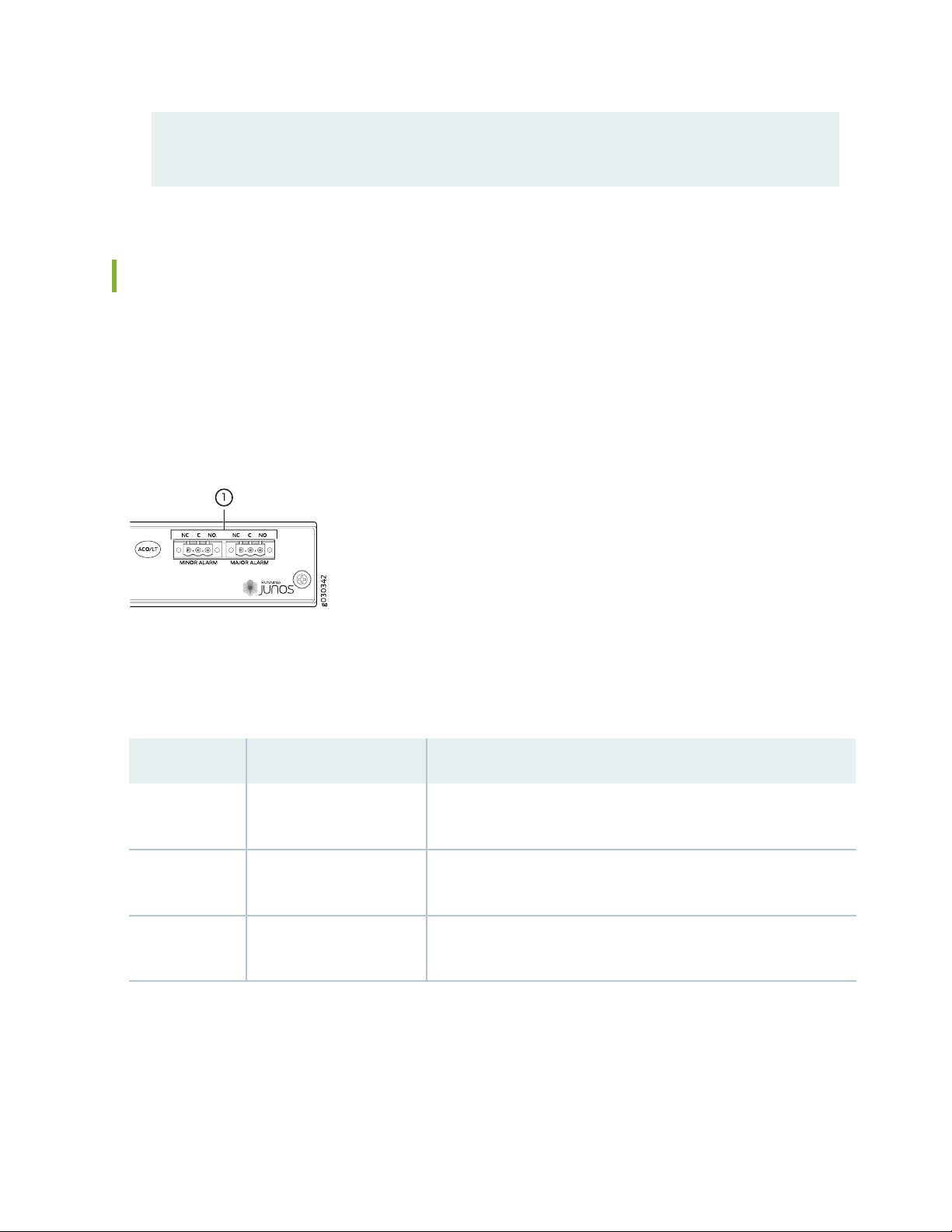
SRX5600 Services Gateway Craft Interface Alarm Relay Contacts
The craft interface has two alarm relay contacts for connecting the device to external alarm devices (see
Figure 8 on page 39). Whenever a system condition triggers either the major or minor alarm on the craft
interface, the alarm relay contacts are also activated. The alarm relay contacts are located on the upper
right of the craft interface.
Figure 8: Alarm Relay Contacts
39
The alarm relay contacts consist of two sets of connectors, one set for each of the two alarms (major and
minor). For each alarm color there are three connectors. Table 10 on page 39 describes the functions of
the connectors.
Table 10: Alarm Relay Contact Functions
FunctionContact NameContact Label
Normally ClosedNC
Current InC
Normally OpenNO
Connects the alarm relay to an external alarm-reporting device that
activates when the circuit between C and NC is closed.
Connects the alarm relay to the current source for the external
alarm-reporting device.
Connects the alarm relay to an external alarm-reporting device that
activates when the circuit between C and NC is open.
Table 11 on page 40 shows the electrical specifications for the alarm relay contacts.
Page 40
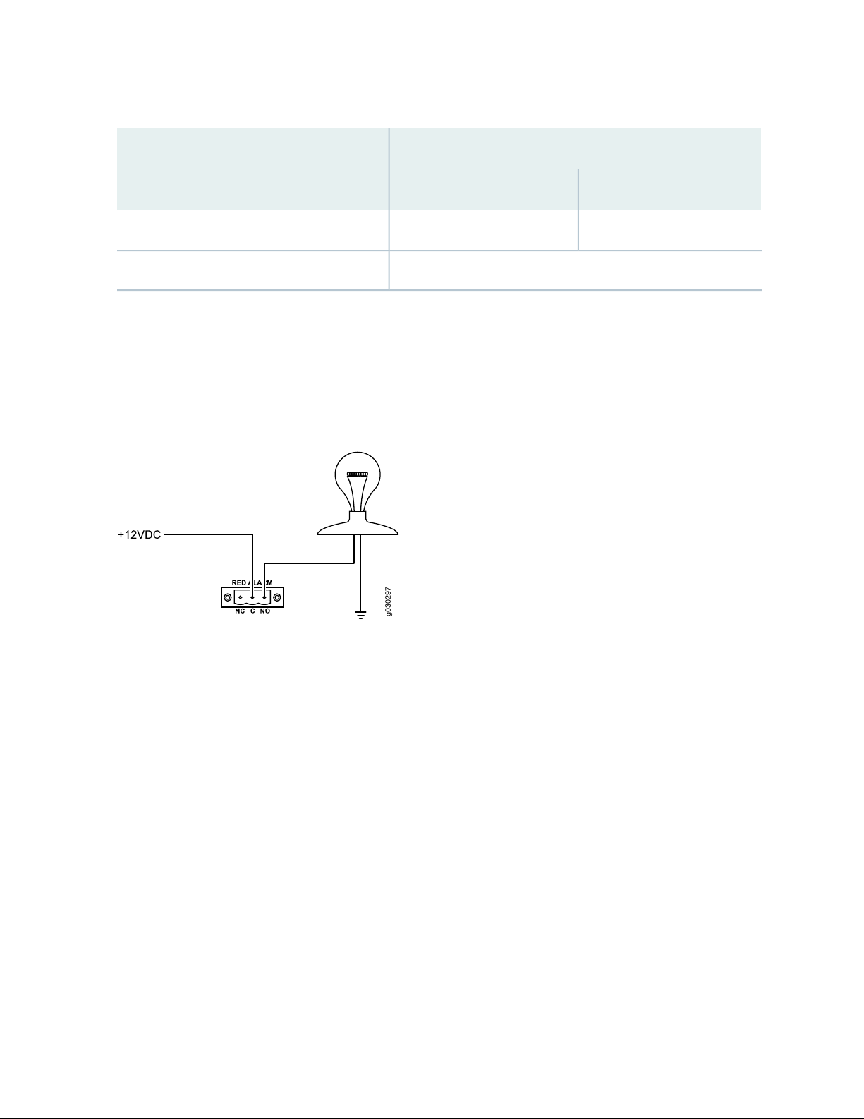
Table 11: Alarm Relay Contact Electrical Specifications
g030297
Current Type
DCAC
30250Maximum Voltage
8 AMaximum Current
Figure 9 on page 40 shows an example wiring diagram for a simple alarm reporting device. In this case the
device is a 12-volt light bulb that illuminates when the device encounters a condition that activates the
major alarm LED and relay contacts. The alarm relay contacts can also be used to activate other devices
such as bells or buzzers.
Figure 9: Example Alarm Reporting Device
40
SRX5600 Services Gateway Cooling System Description
The cooling system consists of the following components:
Fan tray
•
Air filter
•
The cooling system components work together to keep all services gateway components within the
acceptable temperature range (see Figure 10 on page 41, Figure 11 on page 42, and Figure 12 on page 42).
The device has one fan tray and one air filter that install vertically in the rear of the device.
Page 41
Two types of fan trays are available:
The standard capacity fan tray has six fans that operate at 432 cubic feet per minute (CFM) at full speed
•
and is adequate for services gateways in which standard-capacity power supplies are installed.
The high-capacity fan tray has six fans that operate at 579 cubic feet per minute (CFM) at full speed and
•
is required when high-capacity power supplies are installed.
High-capacity fan trays satisfy cooling requirements for high-capacity power supplies and for high-density
SPCs, and must be upgraded for proper cooling.
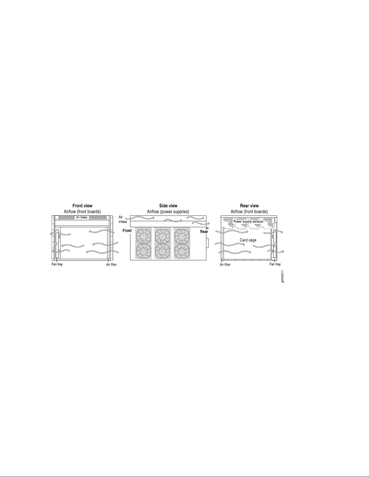
The air intake to cool the chassis is located on the side of the chassis next to the air filter. Air is pulled
through the chassis toward the fan tray, where it is exhausted out the side of the system. The air intake
to cool the power supplies is located in the front of the device above the craft interface. The exhaust for
the power supplies is located on the rear bulkhead power supplies.
Each fan has an LED that displays its status. The fan LEDs are located on the top left of the craft interface.
Figure 10: Airflow Through the Chassis
41
The host subsystem monitors the temperature of the services gateway components. When the device is
operating normally, the fans function at lower than full speed. If a fan fails or the ambient temperature
rises above a threshold, the speed of the remaining fans is automatically adjusted to keep the temperature
within the acceptable range. If the ambient maximum temperature specification is exceeded and the system
cannot be adequately cooled, the Routing Engine shuts down the system by disabling output power from
each power supply.
Page 42

Figure 11: Fan Tray
42
Figure 12: Air Filter
RELATED DOCUMENTATION
Maintaining the Fan Tray on the SRX5600 Services Gateway | 241
Maintaining the Air Filter on the SRX5600 Services Gateway | 244
Troubleshooting the SRX5600 Services Gateway Cooling System | 391
Page 43

Replacing the SRX5600 Services Gateway Fan Tray | 242
Replacing the SRX5600 Services Gateway Air Filter | 245
SRX5600 Services Gateway Craft Interface Fan LEDs | 35
SRX3400 and SRX5600 Services Gateways Air Deflector Kits
Optional air deflector kits are available that let you install the SRX3400 and SRX5600 Services Gateways
in a hot aisle/cold aisle ventilation environment. These kits convert the services gateway from side-to-side
ventilation into front-to-back ventilation. The air deflectors contain no additional fans, so they require no
additional electrical power.
The air deflector kits consist of four main components: two intake/exhaust boxes and two side plenums.
The two intake/exhaust boxes are identical to each other, as are the side plenums.
43
The intake/exhaust boxes are installed above and below the services gateway to direct intake air from the
air space in front of the services gateway into the side plenum mounted on the intake side of the device.
The intake air plenum directs air into the services gateway, and the exhaust air plenum collects the exhaust
air on the opposite side of the device. The exhaust plenum directs the exhausted air into the intake/exhaust
boxes above and below the unit, where it is expelled into the air space behind the services gateway.
The air deflector kit requires additional space around the services gateway, increasing its overall height
and width as described in Table 12 on page 43.
Table 12: Services Gateway and Air Deflector Dimensions
SRX5600 Services GatewaySRX3400 Services GatewaySpecification
8 U (14 in. or 35.6 cm)3 U (5.25 in. or 13.3 cm)Services gateway height
6 U (10.5 in. or 26.7 cm)4 U (7 in. or 17.8 cm)Additional height required for air
deflector kit
14 U (24.5 in. or 62.2 cm)7 U (12.25 in. or 31.1 cm)Total height of services gateway and air
deflector kit
17.5 in. (44.5 cm)17.5 in. (44.5 cm)Services gateway chassis width
Additional width required for air deflector
kit
5.6 in. (14.2 cm) per side
11.2 in. (28.4 cm) total
5.6 in. (14.2 cm) per side
11.2 in. (28.4 cm) total
Page 44

Table 12: Services Gateway and Air Deflector Dimensions (continued)
g036126
g030308
SRX5600 Services GatewaySRX3400 Services GatewaySpecification
28.7 in. (72.9 cm)28.7 in. (72.9 cm)Total width of services gateway and air
deflector kit
Figure 13 on page 44 and Figure 14 on page 44 show the SRX3400 and SRX5600 Services Gateways,
respectively, installed in typical four-post mounting racks with the air deflector kit parts in place.
Figure 13: SRX3400 Services Gateway Air Deflector Kit
44
Figure 14: SRX5600 Services Gateway Air Deflector Kit (Services Gateway Chassis Contents Omitted
for Clarity)
RELATED DOCUMENTATION
Page 45

SRX3400 Services Gateway Chassis
SRX5600 Services Gateway Chassis | 27
SRX5600 Power System
IN THIS SECTION
SRX5600 Services Gateway Power System Overview | 45
SRX5600 Services Gateway AC Power Supply | 47
SRX5600 Services Gateway AC Power Supply Specifications | 49
SRX5600 Services Gateway AC Power Supply LEDs | 49
AC Power Cord Specifications for the SRX5600 Services Gateway | 50
45
AC Power Circuit Breaker Requirements for the SRX5600 Services Gateway | 53
SRX5600 Services Gateway DC Power Supply | 53
SRX5600 Services Gateway DC Power Supply Specifications | 54
SRX5600 Services Gateway DC Power Supply LEDs | 55
DC Power Cable Specifications for the SRX5600 Services Gateway | 56
DC Power Cable Lug Specifications for the SRX5600 Services Gateway | 57
DC Power Circuit Breaker Requirements for the SRX5600 Services Gateway | 57
DC Power Source Cabling for the SRX5600 Services Gateway | 58
SRX5600 Services Gateway Chassis Grounding Point Specifications | 59
SRX5600 Services Gateway Grounding-Cable Lug Specification | 60
SRX5600 Services Gateway Power System Overview
The services gateway uses either AC or DC power supplies. The services gateway is configurable with
two, three, or four AC power supplies or two or four DC power supplies. The power supplies are located
horizontally at the rear of the chassis in slots PEM0 through PEM3 (left to right). The power supplies
connect to the midplane, which distributes the different output voltages produced by the power supplies
to the services gateway components, depending on their voltage requirements. Each power supply is
cooled by its own internal cooling system.
Page 46

CAUTION: The services gateway cannot be powered from AC and DC power supplies
simultaneously. The first type of power supply detected by the services gateway when
initially powered on determines the type of power supply allowed by the services
gateway. All installed power supplies of the other type are disabled by the services
gateway. If you install a power supply of the other type while the services gateway is
operating, the services gateway disables the power supply and generates an alarm.
Redundant power supplies are hot-removable and hot-insertable. When you remove a power supply from
a services gateway that uses a nonredundant power supply configuration, the services gateway might shut
down depending on your configuration.
Depending on the types of power supplies installed and their input voltages, the power distribution in the
services gateway chassis is either shared or zoned. Table 13 on page 46 summarizes the available power
supply types, their output capacities, and their redundancy and power distribution schemes. For detailed
power supply specifications, see “SRX5600 Services Gateway AC Power Supply Specifications” on page 49
or “SRX5600 Services Gateway DC Power Supply Specifications” on page 54.
46
Table 13: Power Supply Type Summary
Power Supply
Type
standard-capacity
standard-capacity
Power
DistributionRedundancyMaximum OutputInput Condition (If Any)
Shared3+11027 WLow-line (110 V Input)AC
2+21590 WHigh-line (220 V Input)
3+11167 WLow-line (110 V Input)AC high-capacity
2+22050 WHigh-line (220 V Input)
Zoned2+2 (1+1 per zone)1600 WDC
2+2 (1+1 per zone)2240 WDIP=0 (60 A Input)DC high-capacity
2+2 (1+1 per zone)2440 WDIP=1 (70 A Input)
NOTE: The services gateway must be running Junos OS Release 12.1X44-D10 or later in order
to use high-capacity AC or DC power supplies.
Page 47

When AC power supplies are installed, the power distribution is shared. All of the power supply power to
all of the components in the services gateway chassis. The power supplies share the load almost equally.
In the low-line (110VAC input) configuration, three power supplies are required to support the services
gateway electrical requirements, and you can install an additional power supply that takes over in case
any of the other three fail. In the high-line (220VAC input) configuration, two power supplies are required
to support the services gateway electrical requirements, and you can install one or two additional power
supplies that will over in case any of the others fail. In the two-PEM high-line configuration, slots PEM0
and PEM1 or PEM2 and PEM3 are used.
When DC power supplies are installed, the power distribution is zoned. The chassis is divided into two
zones numbered 0 and 1. Each zone is powered by one or two power supplies. Two power supplies are
required to support the services gateway electrical requirements, and you can install two additional power
supplies so that each zone has an extra power supply that takes over in case the first power supply fails.
Table 14 on page 47
Table 14: SRX5600 Services Gateway Power Distribution (DC Power Supplies)
Provide Power To:Power SuppliesZone
47
PEM0 or PEM2Zone 0
PEM1 or PEM3Zone 1
Bottom slots 0 and 1 for SCBs
•
Card slots 0 and 1 for SPCs or interface cards (IOCs, Flex
•
IOCs, or MPCs)
Card slots 2 through 5 for SPCs or interface cards (IOCs, Flex
•
IOCs, or MPCs)
SRX5600 Services Gateway AC Power Supply
Each AC power supply consists of one AC appliance inlet, an AC switch, a fan, and LEDs to monitor the
status of the power supply. Figure 15 on page 48 and Figure 16 on page 48 show the power supplies. For
standard-capacity power supplies, each inlet requires a dedicated AC power feed and a dedicated
15 A (250 VAC)circuit breaker. For high-capacity power supplies, each inlet requires a dedicated AC power
feed and a dedicated 16 A @ 100 VAC or 16 A @ 200 VAC circuit breaker, or as required by local code.
Page 48
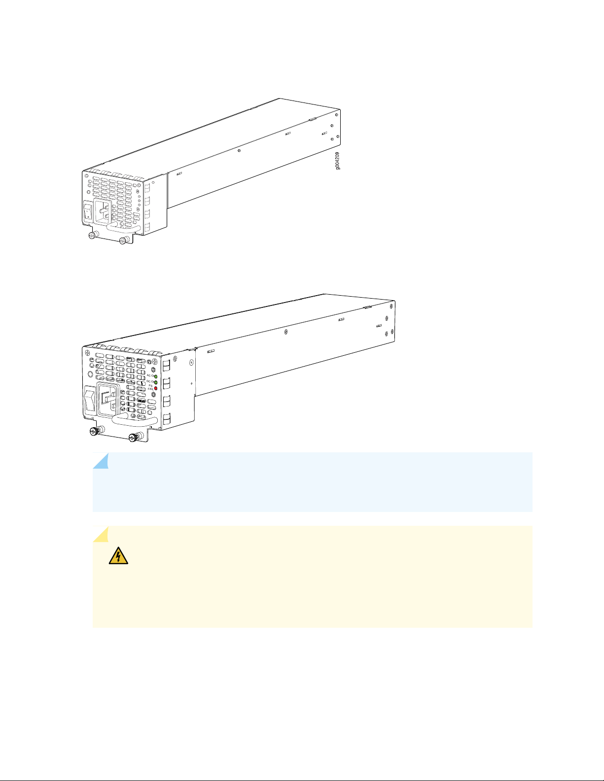
Figure 15: Standard-Capacity AC Power Supply
AC OK
DC OK
PS
FAIL
Figure 16: High-Capacity AC Power Supply
48
NOTE: The services gateway must be running Junos OS Release 12.1X44-D10 or later in order
to use high-capacity AC power supplies.
WARNING: The services gateway is pluggable type A equipment installed in a
restricted-access location. It has a separate protective earthing terminal (sized for UNC
1/4-20 ground lugs) provided on the chassis in addition to the grounding pin of the
power supply cord. This separate protective earthing terminal must be permanently
connected to earth.
Page 49

SRX5600 Services Gateway AC Power Supply Specifications
Table 15 on page 49 lists the AC power supply electrical specifications.
Table 16 on page 49 lists the AC power system electrical specifications.
Table 15: AC Power Supply Electrical Specifications
Specification
Item High-CapacityStandard-Capacity
49
Maximum output power
AC input current rating
1027 W (low line)
1590 W (high line)
14.5 A @ 110 VAC maximum
11.0 A @ 200 VAC maximum
Operating range: 100 - 240 VAC (nominal)AC input voltage
50 to 60 Hz (nominal)AC input line frequency
Table 16: AC Power System Specifications
Normal-Capacity
Low-Line (110V)Item
per power supply
Normal-Capacity
High-Line (220V)
1167 W (low line)
2050 W (high line)
16 A @ 110 VAC maximum
15.1 A @ 200 VAC maximum
High-Capacity
Low-Line (110V)
High-Capacity
High-Line (220V)
2+23+12+23+1Redundancy
2050 W1167 W1590 W1027 WOutput power (maximum)
4100 W3501 W3180 W3081 WOutput power (maximum)
per system
SRX5600 Services Gateway AC Power Supply LEDs
Each AC power supply faceplate contains three LEDs that indicate the status of the power supply (see
Table 17 on page 50). The power supply status is also reflected in two LEDs on the craft interface. In
addition, a power supply failure triggers the red alarm LED on the craft interface.
Page 50

Table 17: AC Power Supply LEDs
50
DescriptionStateColorLabel
AC power input voltage is below 78 VAC.OffAmberAC OK
AC power input voltage is within 78–264 VAC.OnGreen
OffGreenDC OK
On
On
DC power outputs generated by the power supply are not within the
normal operating ranges.
DC power outputs generated by the power supply are within the
normal operating ranges.
Power supply is functioning normally.OffRedPS FAIL
Power supply is not functioning normally and its output voltage is out
of regulation limits. Check AC OK and DC OK LEDs for more
information.
AC Power Cord Specifications for the SRX5600 Services Gateway
Each AC power supply has a single AC appliance inlet located on the power supply that requires a dedicated
AC power feed. Most sites distribute power through a main conduit that leads to frame-mounted power
distribution panels, one of which can be located at the top of the rack that houses the services gateway.
An AC power cord connects each power supply to the power distribution panel.
The services gateway is not shipped with AC power cords. You must order power cords separately using
the model number shown in Table 18 on page 50. The C19 appliance coupler end of the cord inserts into
the AC appliance inlet coupler, type C20 (right angle) as described by International Electrotechnical
Commission (IEC) standard 60320. The plug end of the power cord fits into the power source receptacle
that is standard for your geographical location.
Table 18 on page 50 provides specifications and Figure 17 on page 52 depicts the plug on the AC power
cord provided for each country or region.
Table 18: AC Power Cord Specifications
Plug TypeElectrical SpecificationModel NumberCountry
SAA/3/15240 VAC, 50 Hz ACCBL-M-PWR-RA-AUAustralia
CH2-16P220 VAC, 50 Hz ACCBL-M-PWR-RA-CHChina
Page 51

Table 18: AC Power Cord Specifications (continued)
Denmark, Italy,
Switzerland, and
United Kingdom)
51
Plug TypeElectrical SpecificationModel NumberCountry
CEE 7/7220 or 230 VAC, 50 Hz ACCBL-M-PWR-RA-EUEurope (except
CEI 23-16/VII230 VAC, 50 Hz ACCBL-M-PWR-RA-ITItaly
JIS 8303125 VAC, 50 or 60 Hz ACCBL-PWR-RA-JP15Japan
NEMA L6-20P220 VAC, 50 or 60 Hz ACCBL-M-PWR-RA-JP
NEMA 5-15P125 VAC, 60 Hz ACCBL-PWR-RA-US15North America
NEMA L5-15P125 VAC, 60 Hz ACCBL-PWR-RA-TWLK-US15
NEMA 6-20250 VAC, 60 Hz ACCBL-M-PWR-RA-US
NEMA L6-20P250 VAC, 60 Hz ACCBL-M-PWR-RA-TWLK-US
BS89/13240 VAC, 50 Hz ACCBL-M-PWR-RA-UKUnited Kingdom
Page 52
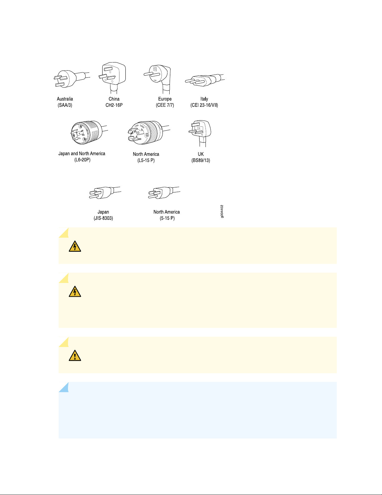
Figure 17: AC Plug Types
52
WARNING: The AC power cord for the services gateway is intended for use with the
services gateway only and not for any other use.
WARNING: To meet safety and electromagnetic interference (EMI) requirements and
to ensure proper operation, you must properly ground the services gateway chassis
before connecting power. See “Grounding the SRX5600 Services Gateway” on page 215
for instructions.
CAUTION: Power cords and cables must not block access to device components or
drape where people could trip on them.
NOTE: In North America, AC power cords must not exceed 4.5 m (approximately 14.75 ft) in
length, to comply with National Electrical Code (NEC) Sections 400-8 (NFPA 75, 5-2.2) and
210-52, and Canadian Electrical Code (CEC) Section 4-010(3). The cords listed in
Table 18 on page 50 are in compliance.
Page 53

AC Power Circuit Breaker Requirements for the SRX5600 Services Gateway
Each AC power supply has a single AC appliance inlet located on the power supply that requires a dedicated
AC power feed. We recommend that you use a customer site circuit breaker rated for 15 A (250 VAC)
minimum for each AC power supply, or as required by local code. Doing so enables you to operate the
services gateway in any configuration without upgrading the power infrastructure.
SRX5600 Services Gateway DC Power Supply
Each DC power supply consists of one DC input (–48 VDC and return), one 40 A (–48 VDC) circuit breaker,
a fan, and LEDs to monitor the status of the power supply. Two different DC power supply types are
available. Figure 18 on page 53 and Figure 19 on page 54 show the power supplies. Each DC power supply
has a single DC input (–48 VDC and return) that requires a dedicated facility circuit breaker.
For high-capacity power supplies, we recommend that you provision 60 A or 70 A per feed, depending
on the selected DIP switch setting.
53
Figure 18: Standard-Capacity DC Power Supply
Page 54
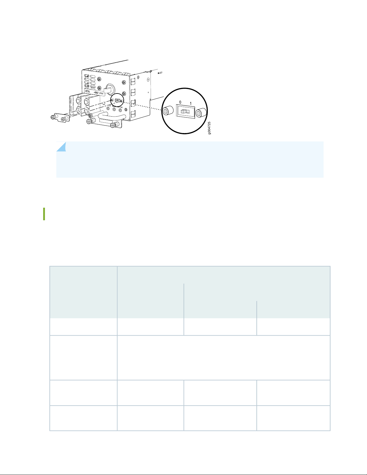
Figure 19: High-Capacity DC Power Supply Faceplate
g004725
NOTE: The services gateway must be running Junos OS Release 12.1X44-D10 or later in order
to use high-capacity DC power supplies.
54
SRX5600 Services Gateway DC Power Supply Specifications
Table 19 on page 54 lists the DC power supply electrical specifications. Table 20 on page 55 lists the DC
power system specifications.
Table 19: DC Power Supply Electrical Specifications
Specification
High Capacity
Item
DC input voltage
DC input current rating
Standard-Capacity DIP=1 (70 A Input)DIP=0 (60 A Input)
Minimum: –40.5 VDC
Nominal: –48 VDC
Operating range: –40.5 to –72 VDC
33.3 A @ –48 V nominal
operating voltage
50 A @ –48 V nominal
operating voltage
2440 W2240 W1600 WMaximum output power
54.2 A @ –48 V nominal
operating voltage
Protector
NoneNone40 AInternal Supplementary
Page 55

Table 20: DC Power System Specifications
Specification
55
High Capacity
Item
power supply
system
Standard-Capacity DIP=1 (70 W Input)DIP=0 (60 W Input)
2+22+22+2Redundancy
2440 W2240 W1600 WOutput power (maximum) per
5200 W4800 W3200 WOutput power (maximum) per
SRX5600 Services Gateway DC Power Supply LEDs
Each DC power supply faceplate contains three LEDs that indicate the status of the power supply (see
Table 21 on page 55). In addition, a power supply failure triggers the red alarm LED on the craft interface.
NOTE: An SCB must be present for the PWR OK LED to go on.
Table 21: DC Power Supply LEDs
OffGreenPWR OK
DescriptionStateColorLabel
Power supply is not functioning normally. Check the INPUT OK LED
for more information.
Page 56

Table 21: DC Power Supply LEDs (continued)
56
DescriptionStateColorLabel
Power supply is functioning normally.On
The main output voltage is out of range (lower limit: 37.5 V to 39.5
V; upper limit: 72.5 V to 76 V).
DC power supply circuit breaker is turned off.OffGreenBRKR ON
DC power input is present and the DC power supply circuit breaker
is turned on.
DC input to the PEM is not present.OffGreenINPUT
DC input is present and is connected in correct polarity.On
DC input is present, but not in valid operating range or connected in
reverse polarity.
OK
Green
OnAmber
On
OnAmber
DC Power Cable Specifications for the SRX5600 Services Gateway
Table 22 on page 56 summarizes the specifications for the power cables, which you must supply.
Table 22: DC Power Cable Specifications
Power
Four 6-AWG (13.3 mm2) cables for each
power supply
CAUTION: You must ensure that power connections maintain the proper polarity.
The power source cables might be labeled (+) and (–) to indicate their polarity. There
is no standard color coding for DC power cables. The color coding used by the external
DC power source at your site determines the color coding for the leads on the power
cables that attach to the terminal studs on each power supply.
SpecificationQuantityCable Type
Minimum 60°C wire, or as required by the
local code
Page 57

DC Power Cable Lug Specifications for the SRX5600 Services Gateway
Crimp area
6 AWG conductor
All measurements in inches
0.28
diameter
each hole
2.25
0.25 0.370.625
g001188
0.55
End view
0.08
The accessory box shipped with the services gateway includes the cable lugs that attach to the terminal
studs of each power supply (see Figure 20 on page 57).
Figure 20: DC Power Cable Lug
CAUTION: Before services gateway installation begins, a licensed electrician must
attach a cable lug to the grounding and power cables that you supply. A cable with an
incorrectly attached lug can damage the services gateway.
57
WARNING: The services gateway is a pluggable type A equipment installed in restricted
access location. It has a separate protective earthing terminal [Metric -M6 and English
- ¼-20 screw) ground lugs] provided on the chassis. This separate protective earth
terminal must be permanently connected to earth.
DC Power Circuit Breaker Requirements for the SRX5600 Services Gateway
Each DC power supply has a single DC input (–48 VDC and return) that requires a dedicated facility circuit
breaker. We recommend that you use a customer site circuit breaker rated for 40 A (–48 VDC) minimum
for each DC power supply, or as required by local code. Doing so enables you to operate the services
gateway in any configuration without upgrading the power infrastructure.
If you plan to operate a DC-powered services gateway at less than the maximum configuration and do
not provision a 40 A (–48 VDC) circuit breaker, we recommend that you provision a circuit breaker for
each DC power supply rated for at least 125% of the continuous current that the system draws at –48 VDC,
or as required by local code.
Page 58

DC Power Source Cabling for the SRX5600 Services Gateway
g030205
AC
Rectifiers
Plant
controls
Power plant and batteries
in same building
Batteries
Ground
window
Central office
ground
Central office
ground
DC power supply on SRX5600
Central office
secondary
DC power
distribution
Figure 21 on page 58 shows a typical DC source cabling arrangement.
Figure 21: Typical DC Source Cabling to the Services Gateway
58
The DC power supplies in slots PEM0 and PEM1 must be powered by dedicated power feeds derived
from feed A, and the DC power supplies in slots PEM2 and PEM3 must be powered by dedicated power
feeds derived from feed B. This configuration provides the commonly deployed A/B feed redundancy for
the system.
CAUTION: You must ensure that power connections maintain the proper polarity.
The power source cables might be labeled (+) and (–) to indicate their polarity. There
is no standard color coding for DC power cables. The color coding used by the external
DC power source at your site determines the color coding for the leads on the power
cables that attach to the terminal studs on each power supply.
WARNING: For field-wiring connections, use copper conductors only.
CAUTION: Power cords and cables must not block access to device components or
drape where people could trip on them.
Page 59

SRX5600 Services Gateway Chassis Grounding Point Specifications
g030296
WARNING: To meet safety and electromagnetic interference (EMI) requirements and
to ensure proper operation, you must properly ground the services gateway chassis
before connecting power. See “Grounding the SRX5600 Services Gateway” on page 215
for instructions.
CAUTION: Before services gateway installation begins, a licensed electrician must
attach cable lugs to the grounding and power cables that you supply. A cable with an
incorrectly attached lug can damage the services gateway.
The services gateway chassis has one grounding point at the upper right corner of the back panel. The
grounding point consists of two threaded holes spaced 0.625-in. (15.86-mm) apart (Figure 22 on page 59).
The grounding point holes fit UNC 1/4–20 screws. The accessory box shipped with the services gateway
includes the cable lug that attaches to the grounding cable and two UNC 1/4–20 screws used to secure
the grounding cable to the services gateway grounding point.
59
Figure 22: SRX5600 Services Gateway Grounding Point
To ground the services gateway, you must connect a grounding cable to earth ground and then attach it
to the chassis grounding point using the two screws provided.
Page 60

NOTE: Additional grounding is provided to an AC-powered services gateway when you plug its
Crimp area
6 AWG conductor
All measurements in inches
0.28
diameter
each hole
2.25
0.25 0.370.625
g001188
0.55
End view
0.08
power supplies into grounded AC power receptacles.
SRX5600 Services Gateway Grounding-Cable Lug Specification
The accessory box shipped with the services gateway includes the cable lug that attaches to the grounding
cable (see Figure 23 on page 60) and two UNC 1/4–20 screws used to secure the grounding cable to the
grounding points.
Figure 23: Grounding Cable Lug
60
CAUTION: Before services gateway installation begins, a licensed electrician must
attach a cable lug to the grounding and power cables that you supply. A cable with an
incorrectly attached lug can damage the services gateway.
NOTE: The same cable lug is used for the DC power cables.
Page 61

SRX5600 Host Subsystem
IN THIS SECTION
SRX5600 Services Gateway Host Subsystem Description | 61
Switch Control Board SRX5K-SCB Overview | 62
Switch Control Board SRX5K-SCB Specifications | 63
Switch Control Board SRX5K-SCBE Overview | 66
Switch Control Board SRX5K-SCBE Specifications | 67
Switch Control Board SRX5K-SCB3 Overview | 70
Switch Control Board SRX5K-SCB3 Specifications | 71
Switch Control Board SRX5K-SCB4 Overview | 73
Switch Control Board SRX5K-SCB4 Specifications | 74
61
Routing Engine SRX5K-RE-1800X4 Overview | 77
Routing Engine SRX5K-RE-1800X4 Specifications | 78
Routing Engine SRX5K-RE-13-20 Overview | 81
Routing Engine SRX5K-RE-13-20 Specifications | 82
Routing Engine SRX5K-RE3-128G Specifications | 85
SRX5600 Services Gateway Host Subsystem Description
The host subsystem is composed of a Routing Engine installed in a Switch Control Board (SCB). The host
subsystem provides the routing and system management functions of the services gateway. You must
install one host subsystem on the device. The host subsystem components are as follows:
Switch Control Board
•
SRX5K-SCB–from Junos OS Release 9.2 to 12.3X48
•
SRX5K-SCBE–from Junos OS Release 12.1X47-D15 and later
•
SRX5K-SCB3–from Junos OS Release 15.1X49-D10 and later
•
SRX5K-SCB4–from Junos OS Release 19.3R1 and later
•
Page 62

NOTE: SRX5K-SCB4 is not supported on SRX5400 Services Gateways.
Routing Engine
•
SRX5K-RE-13-20–from Junos OS Release 9.2 to 12.3X48
•
SRX5K-RE-1800X4–from Junos OS Release 12.1X47-D15 and later
•
SRX5K-RE3-128G–from Junos OS Release 19.3R1 and later
•
NOTE: You can only configure the following combination of Routing Engine and SCB within a
host subsystem:
SRX5K-RE-13-20 and SRX5K-SCB
•
SRX5K-RE-1800X4 and SRX5K-SCBE
•
SRX5K-RE-1800X4 and SRX5K-SCB3
•
62
SRX5K-RE-1800X4 and SRX5K-SCB4
•
SRX5K-RE3-128G and SRX5K-SCB3 or SRX5K-SCB4
•
The host subsystem has three LEDs that display its status. The host subsystem LEDs are located in the
middle of the craft interface.
Switch Control Board SRX5K-SCB Overview
The Switch Control Board (SCB) provides the following functions:
Powers on and powers off IOCs and SPCs
•
Controls clocking, system resets, and booting
•
Monitors and controls system functions, including fan speed, board power status, PDM status and
•
control, and the system front panel
Provides interconnections to all the IOCs within the chassis through the switch fabrics integrated into
•
the SCB
When the SCB is part of a host subsystem, the Routing Engine installs directly into a slot on the SCB (see
Figure 24 on page 63).
Page 63

Figure 24: SRX5K-SCB
63
You must install at least one SCB in the services gateway as part of a host subsystem. You can install a
second SCB for redundancy.
The SCBs install horizontally into the slots at the bottom of the card cage labeled 0 and 1. If any slots are
empty, you must install a blank panel.
For detailed information about SCBs supported by the services gateway, see the SRX5400, SRX5600, and
SRX5800 Services Gateway Card Reference at www.juniper.net/documentation/.
Switch Control Board SRX5K-SCB Specifications
The SRX5K-SCB Switch Control Board (SCB) (Figure 25 on page 64) performs the following functions:
Powers on and powers off I/O cards (IOCs) and Services Processing Cards (SPCs)
•
Controls clocking, system resets, and booting
•
Monitors and controls system functions, including fan speed, board power status, PDM status and
•
control, and the system front panel
Provides interconnections to all the IOCs within the chassis through the switch fabrics integrated into
•
the SCB
Page 64
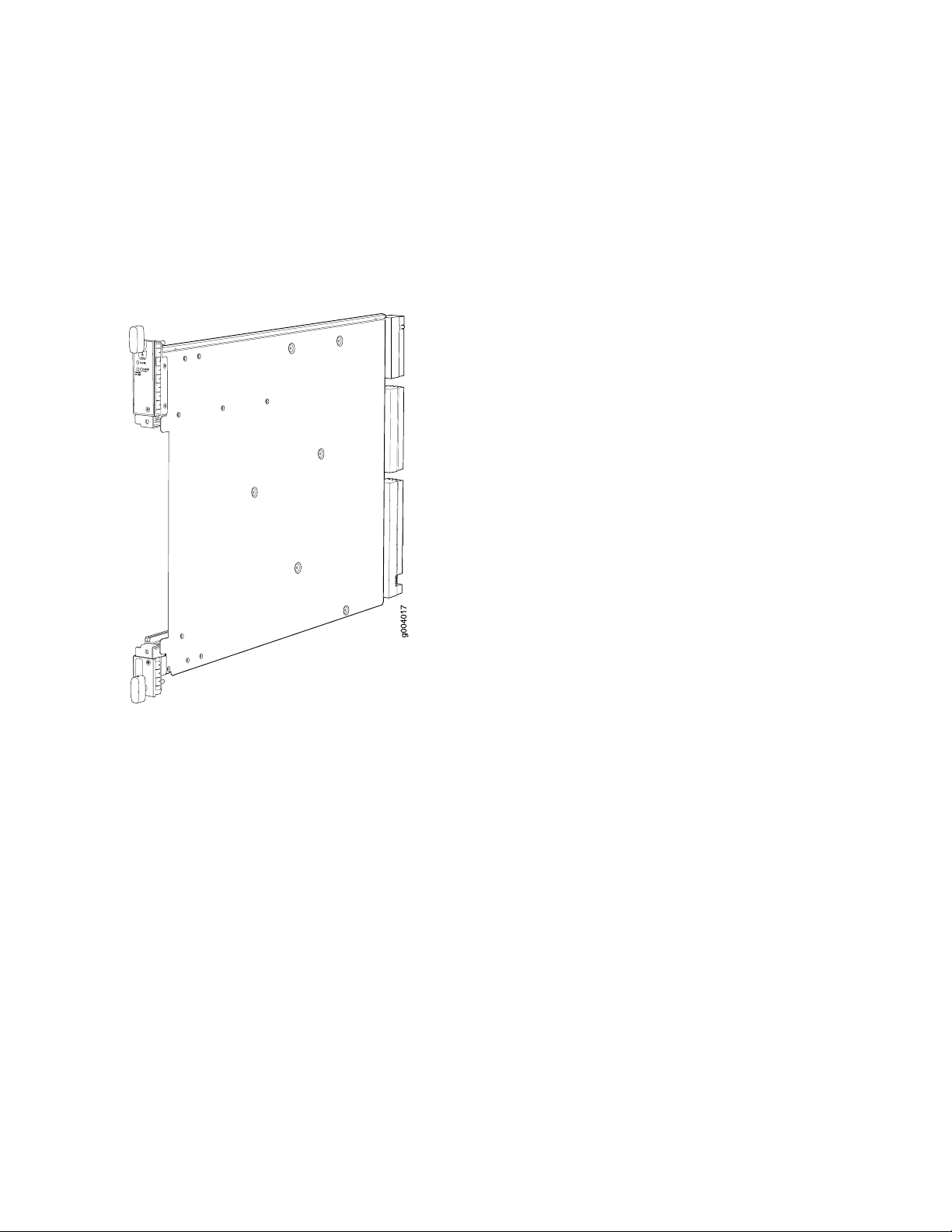
SRX5400 and SRX5600 Services Gateways have one SCB each installed and you can install a second SCB
for redundancy. The SRX5800 Services Gateway has two SCBs installed and you can install a third SCB
for switch fabric redundancy.
The host subsystem is composed of a Routing Engine installed directly into a slot on the faceplate of the
SCB. When there is no Routing Engine is a SCB, its slot must be covered with a blank panel.
Figure 25: Switch Control Board SRX5K-SCB
64
Each SCB consists of the following components:
Chassis management Ethernet switch.
•
I2C bus logic, used for low-level communication with each component.
•
Component redundancy circuitry.
•
Gigabit Ethernet switch that is connected to the embedded CPU complex on all components.
•
Switch fabric—Provides the switching functions for the IOCs.
•
Control FPGA—Provides the Peripheral Component Interconnect (PCI) interface to the Routing Engine.
•
1000Base-T Ethernet controller—Provides a 1-Gbps Ethernet link between the Routing Engines.
•
Ethernet switch—Provides 1-Gbps link speeds between the Routing Engine and the IOCs.
•
Page 65

Circuits for chassis management and control.
•
Power circuits for the Routing Engine and SCB.
•
65
Description
Supported Slots
LEDs
SCB with slot for Routing Engine
•
Maximum throughput: 75 Gbps per slot
•
Junos OS Release 9.2 and laterSoftware release
•
Slot for Routing EngineCables and connectors
NoneControls
SRX5400–Only bottom slots 0 and 1/0
•
SRX5600–Only bottom slots 0 and 1
•
SRX5800–Only center slots 0, 1, and 2/6
•
150 WPower Requirement
Approximately 10 lb (4.5 kg)Weight
OK/FAIL LED, one bicolor:
Green–The SCB is operating normally.
•
Red–The SCB has failed and is not operating normally.
•
Off–The SCB is powered down.
•
FABRIC ONLY LED:
Green–The SCB is operating in fabric-only mode.
•
Off–The SCB is operating in fabric/control board mode.
•
FABRIC ACTIVE LED:
Green–The fabric is in active mode.
•
Page 66
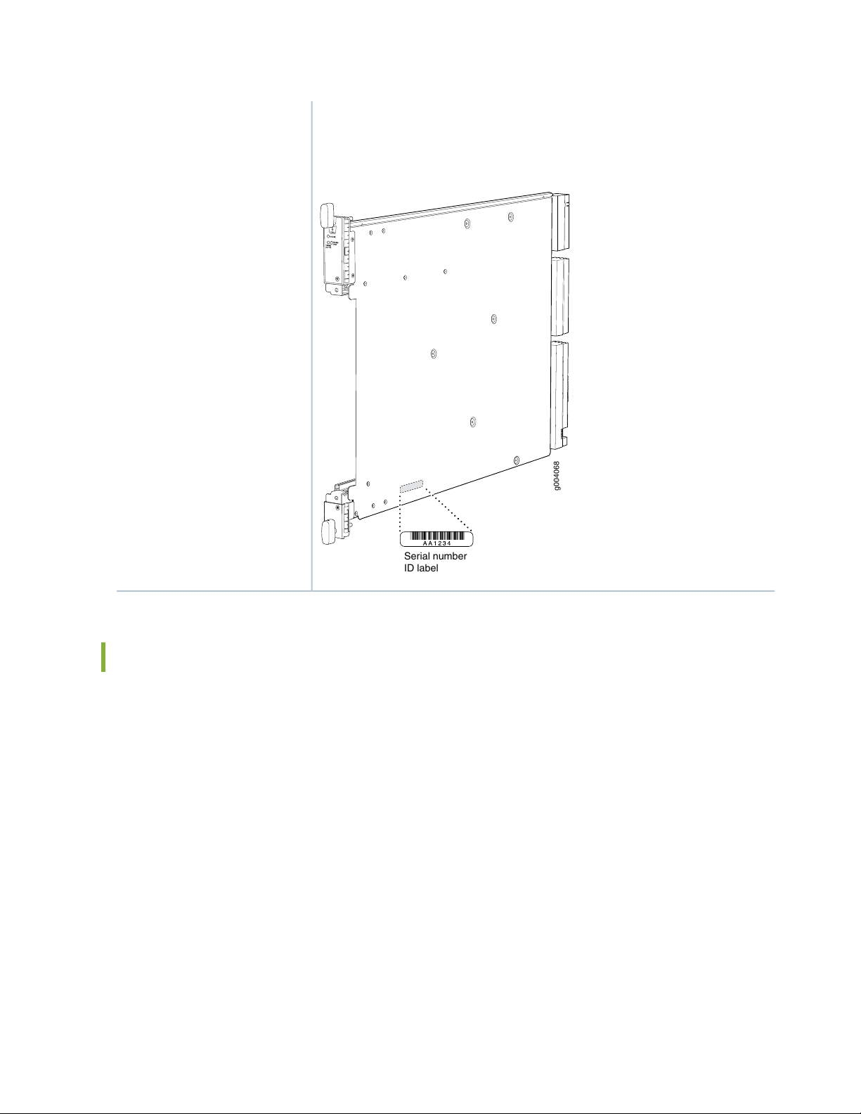
g004068
Serial number
ID label
66
Serial Number Location
The serial number label is located as shown in Figure 26 on page 66.
Figure 26: SCB Serial Number Label
Switch Control Board SRX5K-SCBE Overview
The SRX5000 line enhanced Switch Control Board (SRX5K-SCBE) caters to high-end security markets
requiring support for higher capacity traffic. The SRX5K-SCBE provides greater interface density (slot and
capacity scale) and improved services.
Some key attributes of the SRX5K-SCBE are:
A bandwidth of 120 Gbps per slot with redundant fabric support and improved fabric performance by
•
using the next-generation fabric (XF) chip.
A centralized clocking architecture that supports clock cleanup and distribution. The Stratum 3 clock
•
module performs clock monitoring, filtering, and holdover in a centralized chassis location.
Full performance with fabric redundancy for higher capacity line cards such as the SRX5K-MPC.
•
The Routing Engine installs directly into a slot on the SRX5K-SCBE as shown in Figure 27 on page 67.
Page 67
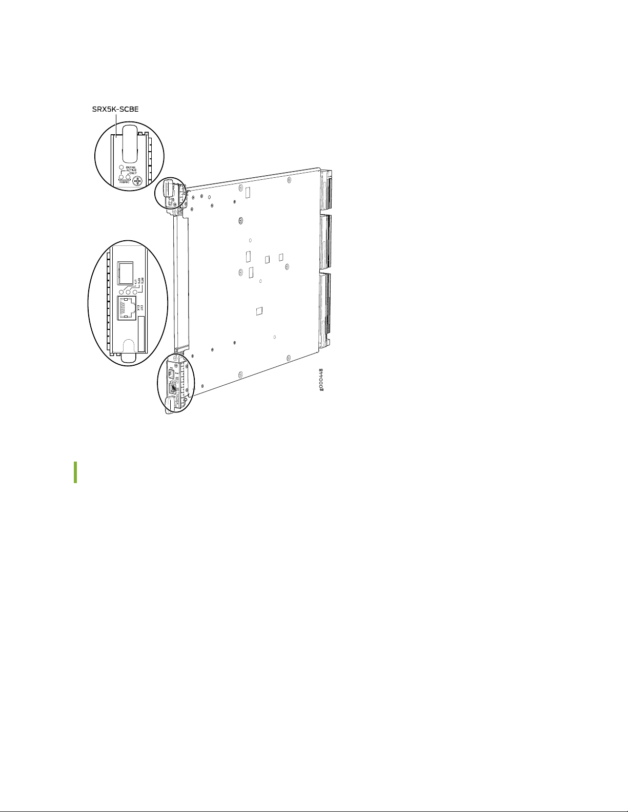
Figure 27: SRX5K-SCBE
67
Switch Control Board SRX5K-SCBE Specifications
Each SRX5K-SCBE consists of the following components:
I2C bus logic for low-level communication with each component
•
Component redundancy circuitry
•
Control Board/Routing Engine primary-role mechanism
•
Gigabit Ethernet switch that is connected to the embedded CPU complex on all components
•
Switch fabric to provide the switching functions for the MPCs
•
1000BASE-T Ethernet controller to provide a 1-Gbps Ethernet link between the Routing Engines
•
Page 68

Power circuits for the Routing Engine and the SRX5K-SCBE
•
LEDs—Provides status of the SRX5K-SCBE and clocking interface
•
68
Description
Software release
Cables and connectors
Controls
Supported slots
Power requirement
Weight
SRX5K-SCBE with slot for Routing Engine
•
Maximum throughput: 120 Gbps per slot
•
Junos OS Release 12.1X47-D15 and later
Slot for Routing Engine
None
SRX5400–Only bottom slots 0 and 1/0
•
SRX5600–Only bottom slots 0 and 1
•
SRX5800–Only center slots 0, 1, and 2/6
•
160 W at 131º F (55º C)
•
130 W at 104º F (40º C)
•
120 W at 77º F (25º C)
•
9.6 lb (4.4 kg) with Routing Engine
Page 69
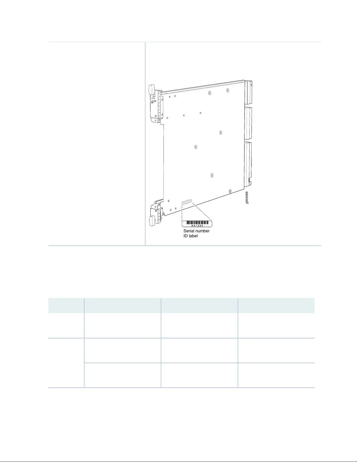
g004068
Serial number
ID label
69
Serial number location
The serial number label is located as shown in Figure 28 on page 69.
Figure 28: SRX5K-SCBE Serial Number Label
SRX5K-SCBE LEDs
Table 23 on page 69 describes the SRX5K-SCBE LEDs and their states.
Table 23: SRX5K-SCBE LEDs
ACTIVE
On steadilyGreenFABRIC
ONLY
OffNone
DescriptionStateColorLabel
Fabric is in active mode.On steadilyGreenFABRIC
SRX5K-SCBE operates in
fabric-only mode.
SRX5K-SCBE operates in
fabric/control board mode.
Page 70
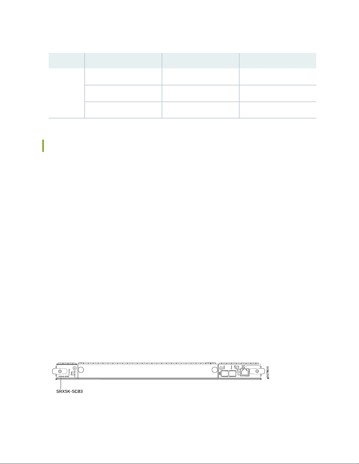
Table 23: SRX5K-SCBE LEDs (continued)
DescriptionStateColorLabel
SRX5K-SCBE is online.On steadilyGreenOK/FAIL
SRX5K-SCBE has failed.On steadilyRed
SRX5K-SCBE is offline.OffNone
Switch Control Board SRX5K-SCB3 Overview
The SRX5K-SCB3 (SCB3) caters to high-end security markets requiring support for higher capacity traffic,
greater interface density (slot and capacity scale), and improved services. The SCB3 is supported on
SRX5400, SRX5600, and SRX5800 Services Gateways.
70
The SCB3 supports the standard midplane and the enhanced midplane.
Some key attributes of the SCB3 are:
With the existing midplane and fabric link speed of 8.36 Gbps, supports a bandwidth of 205 Gbps per
•
slot with redundant fabric support and 308 Gbps per slot without redundancy.
With the enhanced midplane and fabric link speed of 10.2 Gbps, supports a bandwidth of 249 Gbps per
•
slot with redundant fabric support and 374 Gbps per slot without redundancy with the enhanced midplane
Improved fabric performance with the next-generation fabric (XF2) chip.
•
Full performance with fabric redundancy for higher-capacity line cards.
•
Support for MPC line cards such as SRX5K-MPC (IOC2) and IOC3 (SRX5K-MPC3-40G10G or
•
SRX5K-MPC3-100G10G) only.
Two 10-Gigabit Ethernet SFP+ ports (These ports are disabled and reserved for future use).
•
The Routing Engine installs directly into a slot on the SCB3, as shown in Figure 29 on page 70.
Figure 29: SRX5K-SCB3
Page 71

Switch Control Board SRX5K-SCB3 Specifications
Each SRX5K-SCB3 (SCB3) consists of the following components:
I2C bus logic for low-level communication with each component
•
Component redundancy circuitry
•
Control Board/Routing Engine primary-role mechanism
•
Gigabit Ethernet switch that is connected to the embedded CPU complex on all components
•
Switch fabric to provide the switching functions for the MPCs
•
Control field-programmable gate array (FPGA) to provide the Peripheral Component Interconnect (PCI)
•
interface to the Routing Engine
Circuits for chassis management and control
•
Power circuits for the Routing Engine and SCB3
•
LEDs to provides status of the SCB3
•
71
Description
Software release
Cables and connectors
Controls
Supported slots
Power requirement
Weight
SCB3 with slot for Routing Engine
Junos OS Release 15.1X49-D10 and later
Slot for Routing Engine
None
SRX5400–Only bottom slots 0 and 1/0
•
SRX5600–Only bottom slots 0 and 1
•
SRX5800–Only center slots 0, 1, and 2/6
•
300 W
9.6 lb (4.4 kg) with Routing Engine
Page 72
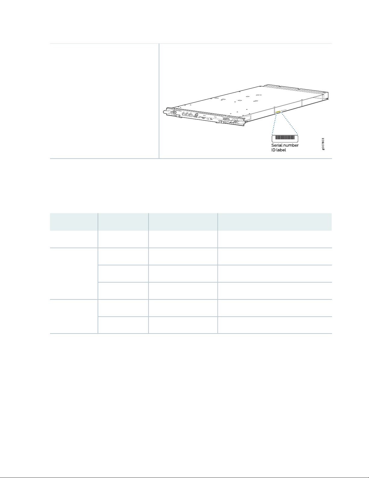
XGE
LINK
LINK
EXT
CLK
BITS
GPS
UTI
72
Serial number location
The serial number label is located as shown in Figure 30 on page 72.
Figure 30: SRX5K-SCB3 Serial Number Label
SRX5K-SCB3 LEDs
Table 24 on page 72 describes the SCB3 LEDs and their states.
Table 24: SRX5K-SCB3 LEDs
DescriptionStateColorLabel
Fabric is in active mode.On steadilyGreenFABRIC ACTIVE
SCB3 is online.On steadilyGreenOK/FAIL
SCB3 has failed.On steadilyRed
SCB3 is offline.Off–
Port is enabled and link is established.On steadilyGreenLINK
Port is disabled or no link is established.Off–
Page 73

Switch Control Board SRX5K-SCB4 Overview
The SRX5K-SCB4 (SCB4) Enhanced Switch Control Board provides improved fabric performance and
bandwidth capabilities for high-capacity line cards using the ZF-based switch fabric. The SCB4 is supported
on SRX5600 and SRX5800 Services Gateways, but not supported on SRX5400 Services Gateways.
The SCB4 supports the standard and the enhanced midplane.
Some key attributes of the SCB4 are:
With the SRX5K-SCB4 Switch Control Board, Increased Fabric Bandwidth mode is the default mode on
•
the SRX5600 and SRX5800 Services Gateways and the services gateways will use six active planes
without any spare planes.
With the Redundant Fabric mode, the SRX5600 and SRX5800 Services Gateways will use four active
•
planes and will have two spare planes.
Full performance with fabric redundancy for higher-capacity line cards.
•
Two 10-Gigabit Ethernet SFP+ ports (These ports are disabled and reserved for future use).
•
73
Increased Fabric Bandwidth mode is the default fabric mode of SCB4. In this mode you must install two
SCB4s in SRX5600 and three SCB4s in SRX5800 Services Gateways/Chassis clusters.
You can change the fabric mode of SCB4 from Increased Fabric Bandwidth mode to Redundant Fabric
mode using the CLI. If you change the fabric mode of SCB4 to Redundant Fabric mode you must install
two SCB4s in SRX5600 and you can install either two or three SCB4s in SRX5800 Services Gateways.
If you are upgrading from SCB3 (Redundant Fabric mode is the default fabric mode in SCB2 and SCB3) to
SCB4 and installing only two SCB4s, you must have Junos OS 19.3R1 or later and change the default fabric
mode of SCB4s to Redundant Fabric mode by using the CLI.
NOTE: To achieve maximum throughput on an SRX5800 Services Gateway, you must install
only two SCB4s (configured in redundant fabric mode) in a fully loaded chassis (for example: 3x
IOC4 + 7x SPC3 + 2x RE3 + 2x SCB4). If you install three SCB4s into the fully loaded chassis
(for example: 3x IOC4 + 7x SPC3 + 2x RE3 + 3x SCB4) the chassis will hit chassis power limit
and one of the line cards will go offline due to power shortage.
You can change the fabric mode by following one of these two methods:
1. Use the CLI command request chassis fabric mode <increased-bandwidth|redundant-fabric>
2. Save the change in the Configuration file
set chassis fabric redundancy-mode increased-bandwidth
set chassis fabric redundancy-mode redundant
Page 74

The Routing Engine installs directly into a slot on the SCB4, as shown in Figure 31 on page 74.
g100573
SRX5K-SCB4
Figure 31: SRX5K-SCB4
74
Switch Control Board SRX5K-SCB4 Specifications
SRX5K-SCB4 (SCB4) consists of the following components:
LEDs to provides status of the SCB4.
•
Circuits for chassis management and control.
•
Power circuits for the Routing Engine and SCB4.
•
Description
Software release
Cables and connectors
SCB4 with slot for SRX5K-RE-1800X4 and SRX5K-RE3-128G Routing
Engines
Junos OS Release 19.3R1 and later
Slot for Routing Engine
Page 75

g100577
Serial number ID label
75
Controls
Supported slots
Power requirement
Cooling requirement
Weight and Dimensions
Serial number location
None
SRX5400–Not supported
•
SRX5600–Only bottom slots 0 and 1
•
SRX5800–Only center slots 0, 1, and 2/6
•
At different temperatures:
55° C: 425 W
•
40° C: 400 W
•
25° C: 385 W
•
For efficient and reliable power and cooling, you must install SRX Series
high-capacity power supplies and fan trays in the SRX Series chassis.
Weight: 13.6 lb (6.2 kg)
•
Width: 15.7 in (39.87 cm)
•
Depth: 21.2 in (53.85 cm)
•
Height: 1.2 in (3.05 cm)
•
The serial number label is located as shown in Figure 32 on page 75.
Figure 32: SRX5K-SCB4 Serial Number Label
Page 76

SRX5K-SCB4 LEDs
Table 25 on page 76 describes the SCB4 LEDs and their states.
Table 25: SRX5K-SCB4 LEDs
DescriptionStateColorLabel
SCB4 is online.On steadilyGreenOK/FAIL
SCB4 has failed.On steadilyRed
SCB4 is offline.Off–
FABRIC
The switch fabric on this board is in Active mode.On steadilyGreenACTIVE
The switch is in Fabric-Only mode.On steadilyGreenONLY
76
port)
SFP+ port is enabled and link is established.On steadilyGreenLINK (XGE
SFP+ port is disabled or no link is established.Off–
On steadilyGreenGPS
Indicates the status of the GPS clocking interface,
and the link is OK.
Activity on the clocking interface.BlinkingYellow
Page 77

Routing Engine SRX5K-RE-1800X4 Overview
g006040
USB
port
Reset
button
Extractor
clip
Extractor
clip
Console
port
Auxiliary
port
Ethernet
port
SSD
slot 2
SSD
slot 1
The enhanced Routing Engine is an Intel-based PC platform that runs Junos OS. Software processes that
run on the Routing Engine maintain the routing tables, manage the routing protocols used on the device,
control the device interfaces, control some chassis components, and provide the interface for system
management and user access to the device.The Routing Engine must be installed directly into the
SRX5K-SCBE. A USB port on the Routing Engine accepts a USB memory device that allows you to load
Junos OS. Figure 33 on page 77 shows the Routing Engine.
Figure 33: SRX5K-RE-1800X4 Routing Engine
77
Three ports located on the Routing Engine connect to one or more external devices on which system
administrators can issue Junos OS CLI commands to manage the services gateway.
The ports function as follows:
AUX–Connects the Routing Engine to a laptop, modem, or other auxiliary device through a serial cable
•
with an RJ-45 connector.
CONSOLE–Connects the Routing Engine to a system console through a serial cable with an RJ-45
•
connector.
ETHERNET–Connects the Routing Engine through an Ethernet connection to a management LAN (or
•
any other device that plugs into an Ethernet connection) for out-of-band management. The port uses
an autosensing RJ-45 connector to support 10/100/1000 Mbps connections. Two small LEDs on the
bottom of the port indicate the connection in use: the LED flashes yellow or green for a 10/100/1000
Mbps connection, and the LED is light green when traffic is passing through the port.
The solid-state drive (SSD) slots located on the Routing Engine provide secondary storage for log files, for
generating core files, and for rebooting the system if the CompactFlash card fails. Currently,
SRX5K-RE-1800X4 only supports one 128-GB SSD.
Page 78

SRX5K-RE-1800X4 Routing Engine Boot Sequence
The services gateway is shipped with three copies of the Junos OS preinstalled on the Routing Engine in
the following locations:
On the CompactFlash card in the Routing Engine
•
On the SSD in the Routing Engine
•
On a USB flash drive that can be inserted into the slot on the Routing Engine faceplate
•
The Routing Engine boots from the storage media in this order: the USB device (if present), the CompactFlash
card, the solid-state drive (SSD), and then the LAN. Normally, the services gateway boots from the copy
of the software on the CompactFlash card.
Routing Engine SRX5K-RE-1800X4 Specifications
78
Each Routing Engine consists of the following components:
CPU—Runs Junos OS to maintain the routing tables and routing protocols.
•
DRAM—Provides storage for the routing and forwarding tables and for other Routing Engine processes.
•
USB port—Provides a removable media interface through which you can install the Junos OS manually.
•
Junos OS supports USB version 1.0 and 2.0.
CompactFlash card—Provides primary storage for software images, configuration files, and microcode.
•
The CompactFlash card is fixed and is inaccessible from outside the device.
Solid-state drive (SSD)—Provides secondary storage for log files, for generating core files, and for rebooting
•
the system if the CompactFlash card fails.
Interface ports—The AUX, CONSOLE, and ETHERNET ports provide access to management devices.
•
Each Routing Engine has one 10/100/1000-Mbps Ethernet port for connecting to a management
network, and two asynchronous serial ports—one for connecting to a console and one for connecting
to a modem or other auxiliary device.
EEPROM—Stores the serial number of the Routing Engine.
•
Reset button—Reboots the Routing Engine when pressed.
•
Online/Offline button—Takes the Routing Engine online or offline when pressed.
•
Extractor clips—Inserts and extracts the Routing Engine.
•
Captive screws—Secures the Routing Engine in place.
•
Description
Routing Engine for SRX5400, SRX5600, and SRX5800 Services Gateways
Page 79

79
Software release
Cables and connectors
Controls
Supported slots
Junos OS Release 12.1X47-D15 and later
Slot for Routing Engine
AUX–Connects the Routing Engine to a laptop, a modem, or another auxiliary
•
device through a cable with an RJ-45 connector.
CONSOLE–Connects the Routing Engine to a system console through a cable with
•
an RJ-45 connector.
ETHERNET–Connects the Routing Engine through an Ethernet connection to a
•
management LAN (or any other device that plugs into an Ethernet connection) for
out-of-band management.
RESET button–Reboots the Routing Engine when pressed.
Front panel slot in an SCB installed in:
SRX5400: Bottom slot 0
•
SRX5600: Bottom slots 0 or 1
•
SRX5800: Center slots 0 or 1
•
NOTE: The services gateway host subsystem Routing Engine must be installed in the
SCB in slot 0. A Routing Engine installed in an SCB in slot 1 only enables dual control
links in chassis cluster configurations.
Power requirement
Weight
90 W
2.4 lb (1.1 kg)
Page 80

80
Serial number location
The serial number label is located as shown in Figure 34 on page 80.
Figure 34: SRX5K-RE-1800X4 Serial Number Label
SRX5K-RE-1800X4 LEDs
Each Routing Engine has four LEDs that indicate its status. The LEDs, labeled MASTER, STORAGE, ONLINE,
and OK/FAIL, are located directly on the faceplate of the Routing Engine. Table 26 on page 80 describes
the Routing Engine LEDs and their states.
Table 26: SRX5K-RE-1800X4 LEDs
DescriptionStateColorLabel
Routing Engine is the primary.On steadilyBlueMASTER
BlinkingGreenSTORAGE
BlinkingGreenONLINE
On steadilyNone
Indicates activity on the SSD or
CompactFlash card.
Routing Engine is transitioning
online.
Routing Engine is functioning
normally.
Routing Engine has failed.On steadilyRedOK/FAIL
Page 81
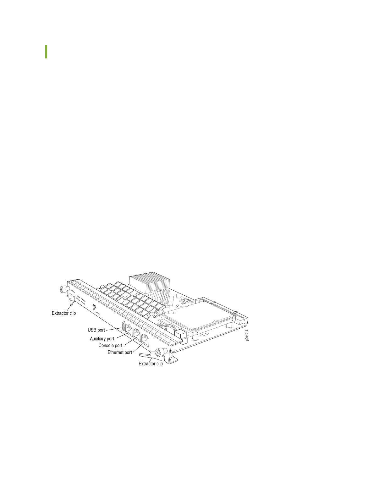
Routing Engine SRX5K-RE-13-20 Overview
The Routing Engine is an Intel-based PC platform that runs Junos OS. Software processes that run on the
Routing Engine maintain the routing tables, manage the routing protocols used on the device, control the
device interfaces, control some chassis components, and provide the interface for system management
and user access to the device.
You must install at least one Routing Engine in the services gateway. You can install a second Routing
Engine if both Routing Engines are running Junos OS Release 10.0 or later.
A second Routing Engine is required if you are using the dual chassis cluster control link feature available
in Junos OS Release 10.0 and later. The second Routing Engine does not perform all the functions of a
Routing Engine and does not improve resiliency or redundancy. The second Routing Engine and the Switch
Control Board (SCB) in which it is installed do not constitute a host subsystem. The only function of the
second Routing Engine is to enable the hardware infrastructure that enables the Chassis Cluster Control
1 port on the Services Processing Card (SPC) used for chassis cluster control links.
If you install only one Routing Engine in the services gateway, you must install it in the slot in the front
panel of SCB0. If you install a second Routing Engine to use the dual chassis cluster control link feature,
you install it in the slot in the front panel of SCB1 (see Figure 35 on page 81).
81
A USB port on the Routing Engine accepts a USB memory card that allows you to load Junos OS.
Figure 35: SRX5K-RE-13-20 Routing Engine
For detailed information about the Routing Engines supported by the services gateway, see the SRX5400,
SRX5600, and SRX5800 Services Gateway Card Reference at www.juniper.net/documentation/.
Page 82

Routing Engine SRX5K-RE-13-20 Specifications
The SRX5K-RE-13-20 Routing Engine (Figure 36 on page 82) is an Intel-based PC platform that runs the
Junos operating system (Junos OS). Software processes that run on the Routing Engine maintain the routing
tables, manage the routing protocols used on the device, control the device interfaces, control some chassis
components, and provide the interface for system management and user access to the device.
Figure 36: Routing Engine
82
You must install at least one Routing Engine in the services gateway. You can install a second Routing
Engine if both Routing Engines are running Junos OS Release 10.0 or later. A second Routing Engine is
required if you are using the dual chassis cluster control link feature available in Junos OS Release 10.0
and later. The second Routing Engine does not perform all the functions of a Routing Engine and does not
improve resiliency or redundancy. The second Routing Engine and the Switch Control Board (SCB) in which
it is installed do not constitute a host subsystem. The only function of the second Routing Engine is to
enable the hardware infrastructure that enables the chassis cluster control 1 port on the Services Processing
Card (SPC) used for chassis cluster control links. If you install only one Routing Engine in the services
gateway, you must install it in the slot in the front panel of SCB0. If you install a second Routing Engine
to use the dual chassis cluster control link feature, you install it in the slot in the front panel of SCB1.
The Routing Engine consists of the following components:
CPU—Runs Junos OS to maintain the services gateway's routing tables and routing protocols. It has a
•
Pentium-class processor.
DRAM—Provides storage for the routing and forwarding tables and for other Routing Engine processes.
•
USB port—Provides a removable media interface through which you can install Junos OS manually. Junos
•
supports USB version 1.0.
Internal flash disk—Provides primary storage for software images, configuration files, and microcode.
•
The disk is a fixed compact flash and is inaccessible from outside the services gateway.
Hard disk—Provides secondary storage for log files, memory dumps, and rebooting the system if the
•
internal compact flash disk fails.
Page 83

HDD LED—Indicates disk activity for the hard disk drive.
•
Management ports—Each Routing Engine has one 10/100-Mbps Ethernet port for connecting to a
•
management network, and two asynchronous serial ports—one for connecting to a console and one for
connecting to a modem or other auxiliary device. The interface ports are labeled AUX, CONSOLE, and
ETHERNET.
EEPROM—Stores the serial number of the Routing Engine.
•
Extractor clips—Used for inserting and extracting the Routing Engine.
•
Captive screws—Secures the Routing Engine in place.
•
The Routing Engine boots from the storage media in this order: the USB device (if present), then the internal
flash disk, then the hard disk, then the LAN.
NOTE: For specific information about Routing Engine components (for example, the amount of
DRAM), issue the show chassis routing-engine command.
83
Software release
Cables and connectors
Controls
Supported Slots
Routing Engine for SRX5400, SRX5600, and SRX5800 Services GatewaysDescription
Junos OS Release 9.2 and later
•
Junos OS Release 10.0 and later required to install a second Routing Engine
•
AUX—Connects the Routing Engine to a laptop, a modem, or another auxiliary device through
a cable with an RJ-45 connector.
CONSOLE—Connects the Routing Engine to a system console through a cable with an RJ-45
connector.
ETHERNET—Connects the Routing Engine through an Ethernet connection to a management
LAN (or any other device that plugs into an Ethernet connection) for out-of-band management.
RESET button—Reboots the Routing Engine when pressed
•
ONLINE/OFFLINE Button—Not supported in the current release
•
Front panel slot in an SCB installed in:
SRX5400: Bottom slot 0
•
SRX5600: Bottom slots 0 or 1
•
SRX5800: Center slots 0 or 1
•
NOTE: The services gateway host subsystem Routing Engine must be installed in the SCB
in slot 0. A Routing Engine installed in an SCB in slot 1 only enables dual control links in
chassis cluster configurations.
Page 84
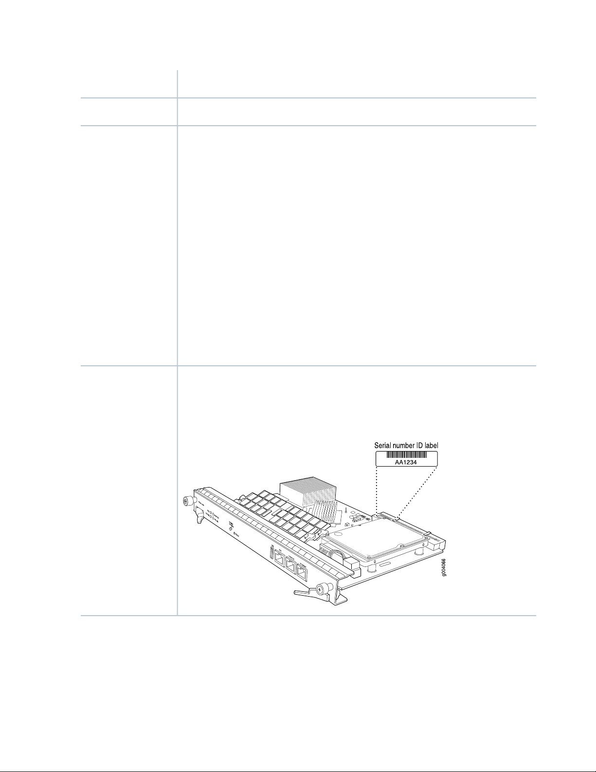
84
90 WPower Requirement
Approximately 2.4 lb (1.1 kg)Weight
LEDs
Serial Number
Location
HDD LED:
Blinking green–The Routing Engine hard disk is functioning normally.
•
MASTER LED:
Blue–The Routing Engine is Primary.
•
NOTE: The SRX5400, SRX5600, and SRX5800 Services Gateways do not support a secondary
or backup Routing Engine, so the MASTER LED should always be lit.
OK/FAIL LED, one bicolor:
Off–The Routing Engine is operating normally.
•
Red–The Routing Engine has failed and is not operating normally.
•
ONLINE LED:
Blinking green–The Routing Engine is coming online.
•
Steady green–The Routing Engine is functioning normally.
•
The serial number label is located on the right side of the top of the Routing Engine as shown
in Figure 37 on page 84
Figure 37: SRX5K-RE-13-20 Serial Number Label
Page 85

Routing Engine SRX5K-RE3-128G Specifications
g100572
21 3 4
5 8
6 7 9 10
IN THIS SECTION
SRX5K-RE3-128G Routing Engine Components | 87
SRX5K-RE3-128G Routing Engine LEDs | 88
SRX5K-RE3-128G Routing Engine Boot Sequence | 89
The Routing Engine maintains the routing tables, manages the routing protocols used on the device, controls
the device interfaces, controls some chassis components, and provides the interfaces for system
management and user access to the device.
Figure 38 on page 85 shows the SRX5K-RE3-128G Routing Engine.
85
Figure 38: SRX5K-RE3-128G Routing Engine Front View
6—1— ONLINE/OFFLINE buttonExtractor clips
7—2— SSD LEDs—DISK1 and DISK2Auxiliary port (AUX)
8—3— USB ports—USB1 and USB2Console port (CONSOLE)
9—4— RESET buttonManagement port (MGMT)
10—5— SSD card slot coverRouting Engine status LEDs—ONLINE, OK/FAIL, and
MASTER
Description
Routing Engine for SRX5400, SRX5600, and SRX5800 Services Gateways, based on Intel’s
Haswell-EP CPU with 6 cores, and 128GB of DDR4 memory. It provides increased control
plane performance and scalability along with virtualization features in the SRX Series
5000 line of chassis.
Software release
Junos OS Release 19.3R1 and later
Page 86

86
Cables and connectors
Controls
Supported slots
Slot for Routing Engine
AUX–Connects the Routing Engine to a laptop, a modem, or another auxiliary device
•
through a cable with an RJ-45 connector.
CONSOLE–Connects the Routing Engine to a system console through a cable with an
•
RJ-45 connector.
MGMT–Connects the Routing Engine through an Ethernet connection to a management
•
LAN (or any other device that plugs into an Ethernet connection) for out-of-band
management.
RESET button–Reboots the Routing Engine when pressed.
Front panel slot in an SCB installed in:
SRX5400: Bottom slot 0
•
SRX5600: Bottom slots 0 or 1
•
SRX5800: Center slots 0 or 1
•
NOTE: The services gateway host subsystem Routing Engine must be installed in the
SCB in slot 0. A Routing Engine installed in an SCB in slot 1 only enables dual control links
in chassis cluster configurations.
Power requirement
Weight
NOTE: In the SRX5600 or SRX5800 Services Gateways chassis cluster configurations,
dual control links functionality is not supported if you mix SRX5K-RE-1800X4 and
SRX5K-RE3-128G Routing Engines. To support dual control links you have to install two
SRX5K-RE3-128Gs.
110 W
2.69 lb (1.22 kg)
Page 87

g100576
Serial number
ID label
87
Serial number location
The serial number label is located as shown in Figure 39 on page 87.
Figure 39: SRX5K-RE3-128G Serial Number Label
SRX5K-RE3-128G Routing Engine Components
Each Routing Engine consists of the following components:
CPU—Runs Junos OS to maintain the routing tables and routing protocols.
•
EEPROM—Stores the serial number of the Routing Engine.
•
DRAM—Provides storage for the routing and forwarding tables and for other Routing Engine processes.
•
One 10-Gigabit Ethernet interface between the Routing Engine and Switch Control Board.
•
Extractor clips—Control the locking system that secures the Routing Engine.
•
Interface ports—The AUX, CONSOLE, and MGMT ports provide access to management devices. Each
•
Routing Engine has one 10/100/1000-Mbps Ethernet port for connecting to a management network,
and two asynchronous serial ports—one for connecting to a console and one for connecting to a modem
or other auxiliary device.
Page 88

NOTE:
The control interface names differ based on the routing engine:
For RE2, the control interfaces are displayed as em0 and em1.
•
For RE3, the control interfaces are displayed as ixlv0 and igb0.
•
For more information, see show chassis cluster interfaces.
Status LEDs—Table 27 on page 88 describes the functions of the ONLINE, OK/FAIL, MASTER, DISK1,
•
and DISK2 LEDs.
ONLINE/OFFLINE button—Takes the Routing Engine online or offline when pressed.
•
NOTE: The ONLINE/OFFLINE button must be pressed for a minimum of 4 seconds.
88
USB1 and USB2 ports—Provide a removable media interface through which you can install Junos OS
•
manually. Junos OS supports USB versions 3.0, 2.0, and 1.1.
RESET button—Reboots the Routing Engine when pressed.
•
SSD1 (primary) and SSD2 (secondary) Solid-state drives (SSD)—Two 200-GB each slim solid-state drives
•
that provide storage for software images, configuration files, microcode, log files, and memory dumps.
The Routing Engine reboots from SSD2 when boot from primary SSD1 fails.
Captive screws—Secures the Routing Engine.
•
SRX5K-RE3-128G Routing Engine LEDs
Each Routing Engine has four LEDs that indicate its status. The LEDs, labeled ONLINE, OK/FAIL, MASTER,
DISK1, and DISK2, are located directly on the faceplate of the Routing Engine. Table 27 on page 88
describes the Routing Engine LEDs and their states.
Table 27: SRX5K-RE3-128G Routing Engine LEDs
DescriptionStateColorLabel
Blinking slowlyGreenONLINE
Routing Engine is in the process of booting BIOS and the
host OS.
Routing Engine is in the process of booting Junos OS.Blinking rapidly
Routing Engine is not online or not functioning normally.Off-
Page 89
Table 27: SRX5K-RE3-128G Routing Engine LEDs (continued)
DescriptionStateColorLabel
Routing Engine is powering up.On steadilyGreenOK/FAIL
89
On steadilyYellow
Routing Engine is not powering up, which indicates
failure.
This Routing Engine is the primary Routing Engine.On steadilyBlueMASTER
Indicates presence of disk activity.BlinkingGreenDISK1
There is no disk activity.Off-
Indicates presence of disk activity.BlinkingGreenDISK2
There is no disk activity.Off-
SRX5K-RE3-128G Routing Engine Boot Sequence
Booting in a SRX5K-RE3-128G Routing Engine follows this sequence—the USB device, SSD1, SSD2, and
LAN. SSD1 is the primary boot device. The boot sequence is tried twice for SSD1 and SSD2.
SRX5600 Line Cards and Modules
IN THIS SECTION
SRX5400, SRX5600, and SRX5800 Services Gateway Card Overview | 90
SRX5600 Services Gateway Card Terminology | 91
Cards Supported on SRX5400, SRX5600, and SRX5800 Services Gateways | 92
SRX5600 Services Gateway Card Cage and Slots | 96
SRX5600 Services Gateway SPC Description | 96
Services Processing Card SRX5K-SPC-2-10-40 Specifications | 97
Services Processing Card SRX5K-SPC-4-15-320 Specifications | 102
Services Processing Card SRX5K-SPC3 Specifications | 107
SRX5600 Services Gateway Interface Card Description | 111
Page 90
Modular Port Concentrator (SRX5K-MPC) Specifications | 113
SRX5K-MPC3-40G10G Specifications | 116
SRX5K-MPC3-100G10G Specifications | 119
MIC with 20x1GE SFP Interfaces (SRX-MIC-20GE-SFP) | 122
MIC with 10x10GE SFP+ Interfaces (SRX-MIC-10XG-SFPP) | 128
MIC with 1x100GE CFP Interface (SRX-MIC-1X100G-CFP) | 133
MIC with 2x40GE QSFP+ Interfaces (SRX-MIC-2X40G-QSFP) | 135
SRX5K-IOC4-10G Specifications | 136
SRX5K-IOC4-MRAT Specifications | 139
I/O Card SRX5K-40GE-SFP Specifications | 143
I/O Card SRX5K-4XGE-XFP Specifications | 145
Flex I/O Card (SRX5K-FPC-IOC) Specifications | 147
Flex I/O Card Port Module SRX-IOC-16GE-SFP Specifications | 149
90
Flex I/O Card Port Module SRX-IOC-16GE-TX Specifications | 151
Flex I/O Card Port Module SRX-IOC-4XGE-XFP Specifications | 152
SRX5400, SRX5600, and SRX5800 Services Gateway Card Overview
The cards described in this guide let you upgrade and customize your SRX5400, SRX5600, or SRX5800
Services Gateway to suit the needs of your network. The following types of cards are available for the
SRX5400, SRX5600, and SRX5800 Services Gateways:
I/O cards (IOCs) provide additional physical network connections to the services gateway. Their primary
•
function is to deliver data packets arriving on the physical ports to the Services Processing Cards (SPCs)
and to forward data packets out the physical ports after services processing.
Flex IOCs have two slots for port modules that add additional physical network connections to the
•
services gateway. Like IOCs, their primary function is to deliver data packets arriving on the physical
ports to the SPCs and to forward data packets out the physical ports after services processing.
Modular Port Concentrators (MPCs) have slots on the front panel that accept smaller cards called Modular
•
Interface Cards (MICs). Each MIC has one or more physical interfaces on it. An MPC with MICs installed
functions in the same way as a regular I/O card (IOC), but allows greater flexibility in adding different
types of Ethernet ports to your services gateway. MPCs and MICs are similar in form and function to
Flex IOCs and port modules. However, the two use different form-factors, so you cannot install port
modules in an MPC, nor can you install MICs in a Flex IOC.
Page 91

Services Processing Cards (SPCs) provide the processing power to run integrated services such as firewall,
•
IPsec and IDP. All traffic traversing the services gateway is passed to an SPC to have services processing
applied to it.
Switch Control Boards (SCBs) power on and power off IOCs and SPCs; control clocking and system
•
resets; and control booting, monitor, and system functions. Each SCB has a slot in the front panel for a
Routing Engine.
Although the following modules are not cards in the sense of having a form-factor that fits the card cage
of the SRX5400, SRX5600, and SRX5800 Services Gateway, this guide also addresses the following modules
that fit into certain SRX5400, SRX5600, and SRX5800 Services Gateway cards:
Routing Engines fit into slots in SCBs and maintain the routing tables, manage the routing protocols used
•
on the device, control the device interfaces and some chassis components, and provide the interface
for system management and user access to the device.
Port modules fit into slots in Flex IOCs and add additional physical network interface ports to the services
•
gateway.
Modular Interface Cards (MICs) fit into slots in MPCs and add additional physical network interface ports
•
to the services gateway. MPCs and MICs are similar in form and function to Flex IOCs and port modules.
However, the two use different form-factors, so you cannot install port modules in an MPC, nor can you
install MICs in a Flex IOC.
91
SRX5600 Services Gateway Card Terminology
Regardless of orientation, this information uses the same terms for all four edges of the card (see
Figure 40 on page 92):
Faceplate—Edge of the card that has connectors to which you connect cables or sockets in which you
•
insert SFP or XFP transceivers.
Connector edge—Edge opposite the faceplate; this edge has the connectors that attach to the midplane.
•
Top edge—Edge at the top of the card when it is vertical.
•
Bottom edge—Edge at the bottom of the card when it is vertical.
•
NOTE: This terminology applies to SPCs, IOCs, MPCs, and SCBs in addition to Routing Engines
and port modules.
Page 92

Figure 40: Card Edges
92
Cards Supported on SRX5400, SRX5600, and SRX5800 Services Gateways
Table 28 on page 92 describes the cards and other modules supported on the SRX5400, SRX5600, and
SRX5800 Services Gateways.
Table 28: Supported Cards for SRX5400, SRX5600, and SRX5800 Services Gateways
Last Supported Junos
Earliest Supported Junos OS Release
Card Name and Model
Number
SPCs
SRX5K-SPC-2-10-40
Specifications
12.1X44-D1012.1X46-D10Services Processing Card
SRX5K-SPC-4-15-320
Specifications
OS Release
SRX5400, SRX5600,
and SRX5800SRX5600 and SRX5800SRX5400
15.1X499.2Not supportedServices Processing Card
Page 93

Table 28: Supported Cards for SRX5400, SRX5600, and SRX5800 Services Gateways (continued)
Last Supported Junos
Earliest Supported Junos OS Release
OS Release
93
Card Name and Model
Number
SRX5K-SPC3 Specifications
Interface Cards
Specifications
Specifications
Specifications
(SRX5K-MPC) Specifications
Specifications
SRX5400, SRX5600,
and SRX5800SRX5600 and SRX5800SRX5400
18.2R1-S118.2R1-S1Services Processing Card
15.1X499.2Not supportedI/O Card SRX5K-40GE-SFP
15.1X499.2Not supportedI/O Card SRX5K-4XGE-XFP
15.1X4910.2Not supportedFlex I/O Card (SRX5K-FPC-IOC)
12.1X46-D1012.1X46-D10Modular Port Concentrator
15.1X49-D1015.1X49-D10SRX5K-MPC3-40G10G
Specifications
Specifications
SCBs
SRX5K-SCB Specifications
SRX5K-SCBE Specifications
SRX5K-SCB3 Specifications
15.1X49-D1015.1X49-D10SRX5K-MPC3-100G10G
19.3R119.3R1SRX5K-IOC4-10G Specifications
19.3R119.3R1SRX5K-IOC4-MRAT
15.1X499.212.1X46-D10Switch Control Board
12.1X47-D1512.1X47-D15Switch Control Board
15.1X49-D1015.1X49-D10Switch Control Board
Page 94

Table 28: Supported Cards for SRX5400, SRX5600, and SRX5800 Services Gateways (continued)
Last Supported Junos
Earliest Supported Junos OS Release
OS Release
94
Card Name and Model
Number
SRX5K-SCB4 Specifications
Other modules
SRX-IOC-16GE-SFP
Specifications
SRX-IOC-16GE-TX
Specifications
SRX-IOC-4XGE-XFP
Specifications
Interface
(SRX-MIC-1X100G-CFP)
SRX5400, SRX5600,
and SRX5800SRX5600 and SRX5800SRX5400
19.3R1Not supportedSwitch Control Board
10.2Not supportedFlex I/O Card Port Module
10.2Not supportedFlex I/O Card Port Module
10.2Not supportedFlex I/O Card Port Module
12.1X46-D1012.1X46-D10MIC with 1x100GE CFP
Interfaces
(SRX-MIC-2X40G-QSFP)
Interfaces
(SRX-MIC-10XG-SFPP)
(SRX-MIC-20GE-SFP)
SRX5K-RE-13-20 Specifications
SRX5K-RE-1800X4
Specifications
12.1X46-D1012.1X46-D10MIC with 2x40GE QSFP+
12.1X46-D1012.1X46-D10MIC with 10x10GE SFP+
12.1X47-D1012.1X47-D10MIC with 20x1GE SFP Interfaces
12.3X489.212.1X46-D10Routing Engine
12.1X47-D1512.1X47-D15Routing Engine
Page 95
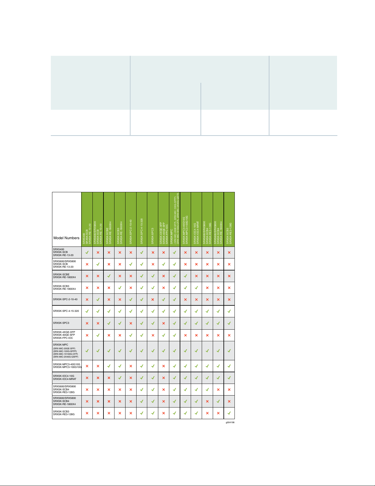
Table 28: Supported Cards for SRX5400, SRX5600, and SRX5800 Services Gateways (continued)
g004198
SRX5400
SRX5K-SCB
SRX5K-RE-13-20
SRX5K-SPC-2-10-40
SRX5K-SPC-4-15-320
SRX5K-SPC3
SRX5K-IOC4-10G
SRX5K-IOC4-MRAT
SRX5K-SCB3
SRX5K-RE3-128G
SRX5600/SRX5800
SRX5K-SCB4
SRX5K-RE3-128G
SRX5600/SRX5800
SRX5K-SCB4
SRX5K-RE-1800X4
SRX5K-4XGE-XFP
SRX5K-40GE-SFP
SRX5K-FPC-IOC
SRX5K-MPC3-40G10G
SRX5K-MPC3-100G10G
SRX5K-SCB3
SRX5K-RE-1800X4
SRX5K-SCBE
SRX5K-RE-1800X4
SRX5600/SRX5800
SRX5K-SCB
SRX5K-RE-13-20
Model Numbers
SRX5K-RE-1800X4
SRX5K-SCBE
SRX5600/SRX5800
SRX5K-SCB
SRX5K-RE-13-20
SRX5400
SRX5K-SCB
SRX5K-RE-13-20
SRX5K-SCB3
SRX5K-RE-1800X4
SRX5K-SPC-2-10-40
SRX5K-SPC-4-15-320
SRX5K-SPC3
SRX5K-MPC3-40G10G
SRX5K-MPC3-100G10G
SRX5K-IOC4-10G
SRX5K-IOC4-MRAT
SRX5K-SCB3
SRX5K-RE3-128G
SRX5600/SRX5800
SRX5K-SCB4
SRX5K-RE3-128G
SRX5600/SRX5800
SRX5K-SCB4
SRX5K-RE-1800X4
SRX5K-4XGE-XFP
SRX5K-40GE-SFP
SRX5K-FPC-IOC
SRX5K-MPC
(SRX-MIC-20GE-SFP)
(SRX-MIC-10XG-SFPP)
(SRX-MIC-1X100G-CFP)
(SRX-MIC-2X40G-QSFP)
SRX5K-MPC
( SRX-MIC-20GE-SFP), (SRX-MIC-10XG-SFPP)
(SRX-MIC-1X100G-CFP), (SRX-MIC-2X40G-QSFP)
Last Supported Junos
Earliest Supported Junos OS Release
OS Release
95
Card Name and Model
Number
SRX5400, SRX5600,
and SRX5800SRX5600 and SRX5800SRX5400
19.3R119.3R1Routing Engine
SRX5K-RE3-128G Specifications
Figure 41 on page 95 is an interoperability matrix that describes the compatibility between various interface
cards for the SRX5400, SRX5600, and SRX5800 Services Gateways.
Figure 41: Interoperability Matrix for SRX5400, SRX5600, and SRX5800 Services Gateways
Page 96

SRX5600 Services Gateway Card Cage and Slots
The card cage is the set of eight horizontal slots in the front of the chassis where you install cards. The
slots are numbered from bottom to top. Table 29 on page 96 describes the types of cards that you can
install into each slot.
Table 29: SRX5600 Services Gateway Card Cage Slots
Eligible Cards
Card Cage Slot SCBFlex IOCIOCMPCSPC
XXXX5
XXXX4
XXXX3
96
XXXX2
XXXX1
XXXX0
X1
X0
SRX5600 Services Gateway SPC Description
The Services Processing Card (SPC) has Services Processing Units (SPUs), which provide the processing
power to run integrated services such as firewall, IPsec, and IDP (see Figure 42 on page 97). All traffic
traversing the services gateway is passed to an SPU to have services processing applied to it. Traffic is
intelligently distributed by interface cards to SPUs for services processing.
The services gateway must have one SPC installed.
You can install an SPC in any of the slots that are not reserved for Switch Control Board (SCB). If a slot is
not occupied by a card, you must install a blank panel to shield the empty slot and to allow cooling air to
circulate properly through the device.
Figure 42 on page 97 shows a typical SPC supported on the services gateway.
Page 97

Figure 42: Typical SPC
g030302
97
For detailed information about SPCs supported by the services gateway, see the SRX5400, SRX5600, and
SRX5800 Services Gateway Card Reference at www.juniper.net/documentation/.
Services Processing Card SRX5K-SPC-2-10-40 Specifications
The SRX5K-SPC-2-10-40 Services Processing Card (SPC) contains two Services Processing Units (SPUs),
which provide the processing power to run integrated services such as firewall, IPsec, and IDP (see
Figure 43 on page 98). All traffic traversing the services gateway is passed to an SPU to have services
processing applied to it. Traffic is intelligently distributed by I/O cards (IOCs) to SPUs for services processing.
The services gateway must have at least one SPC installed. You can install additional SPCs to increase
services processing capacity.
You can install SPCs in any of the slots that are not reserved for Switch Control Boards (SCBs). If a slot is
not occupied by a card, you must install a blank panel to shield the empty slot and to allow cooling air to
circulate properly through the device.
Figure 43 on page 98 shows a typical SPC supported on the services gateway.
Page 98
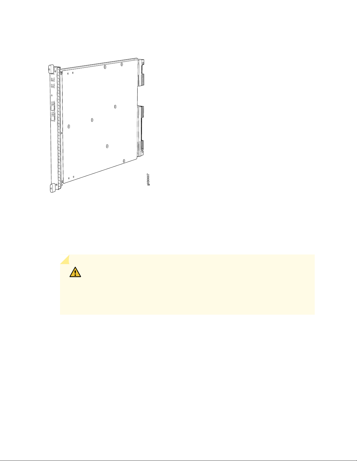
Figure 43: Services Processing Card SRX5K-SPC-2-10-40
98
Each SPC consists of the following components:
SPC cover, which functions as a ground plane and a stiffener.
•
Two small form-factor pluggable (SFP) chassis cluster control ports for connecting multiple devices into
•
a redundant chassis cluster. See Chassis Cluster User Guide for SRX Series Devices for more information
about connecting and configuring redundant chassis clusters.
CAUTION: If you face a problem running a Juniper Networks device that uses a
third-party optic or cable, the Juniper Networks Technical Assistance Center (JTAC)
can help you diagnose the source of the problem. Your JTAC engineer might
recommend that you check the third-party optic or cable and potentially replace it
with an equivalent Juniper Networks optic or cable that is qualified for the device.
Fabric interfaces.
•
Two Gigabit Ethernet interfaces that allow control information, route information, and statistics to be
•
sent between the Routing Engine and the CPU on the SPCs.
Two interfaces from the SCBs that enable the boards to be powered on and controlled.
•
Physical SPC connectors.
•
Midplane connectors and power circuitry.
•
Page 99

Processor subsystem, which includes a 1.2-GHz CPU, system controller, and 1 GB of SDRAM.
•
LEDs on the faceplate that indicate the SPC and SPU status.
•
SPC with two SPUsDescription
Junos OS Release 9.2 and laterSoftware release
•
99
Cables and
connectors
Supported Slots
Requirement
CHASSIS CLUSTER CONTROL 0 and CHASSIS CLUSTER CONTROL 1–SFP ports for control
links in chassis cluster configurations.
Supported SFP transceivers:
1000BASE-LH (model numbers SRX-SFP-1GE-LH, SRX-SFP-1GE-LH-ET)
1000BASE-LX (model numbers SRX-SFP-1GE-LX, SRX-SFP-1GE-LX-ET)
1000BASE-SX (model numbers SRX-SFP-1GE-SX, SRX-SFP-1GE-SX-ET)
NoneControls
SRX5600–Any slot, except the bottom slots 0 or 1 which are reserved for SCB/RE.
•
SRX5800–Any slot, except the slots 0 or 1 which are reserved for SCB/RE.
•
Maximum 351 WPower
Approximately 13 lb (5.9 kg)Weight
Page 100

LEDs
100
 Loading...