

Page 1

Quick Start Guide
SRX550 High Memory Services Gateway
IN THIS GUIDE
SRX550 High Memory Services Gateway Overview | 1
SRX550 High Memory Front Panel and Rear Panel | 2
Factory-Default Settings | 3
Install the Device in a Rack | 5
Connect the Grounding Cable | 6
Power On the Device | 8
Configure Using J-Web | 9
Plug and Play | 11
Customize the Basic Configuration with J-Web | 12
Next Steps | 13
Reference | 13
SRX550 High Memory Services Gateway Overview
The SRX550 High Memory Services Gateway is a large branch office gateway that combines security, routing, switching,
and WAN interfaces with next-generation firewall and advanced threat mitigation capabilities for cost-effective, secure
connectivity across distributed enterprise locations. The services gateway simplifies network complexity, protects and
prioritizes network resources, and improves user and application experience.
The SRX550 High Memory Services Gateway comes with 4 GB of DRAM memory and 8 GB of flash memory.
Package Contents
The SRX550 High Memory Services Gateway is shipped with the following parts:
Page 2
RJ-45 cable with DB-9 adapter
•
AC or DC power supply
•
Power cable (for AC power supply only)
•
USB cable
•
Mounting brackets and screws
•
Documentation Roadmap and Product Warranty
•
End User License Agreement
•
Register the Product
Register product serial numbers on the Juniper Networks website and update the installation base data if there is any
addition or change to the installation base or if the installation base is moved. Juniper Networks will not be held accountable
for not meeting the hardware replacement service-level agreement for products that do not have registered serial numbers
or accurate installation base data.
2
Register your product at https://tools.juniper.net/svcreg/SRegSerialNum.jsp.
Update your installation base at https://www.juniper.net/customers/csc/management/updateinstallbase.jsp.
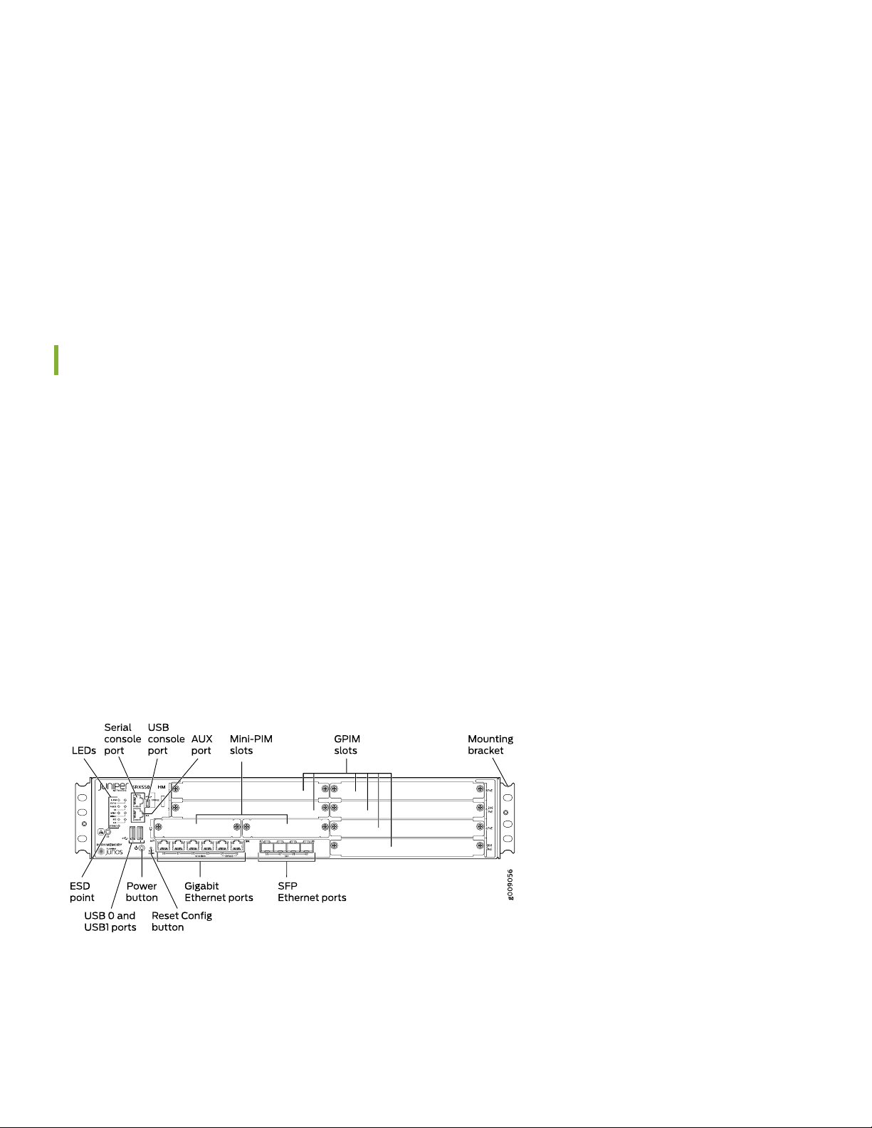
SRX550 High Memory Front Panel and Rear Panel
Figure 1: Front Panel Components
Page 3
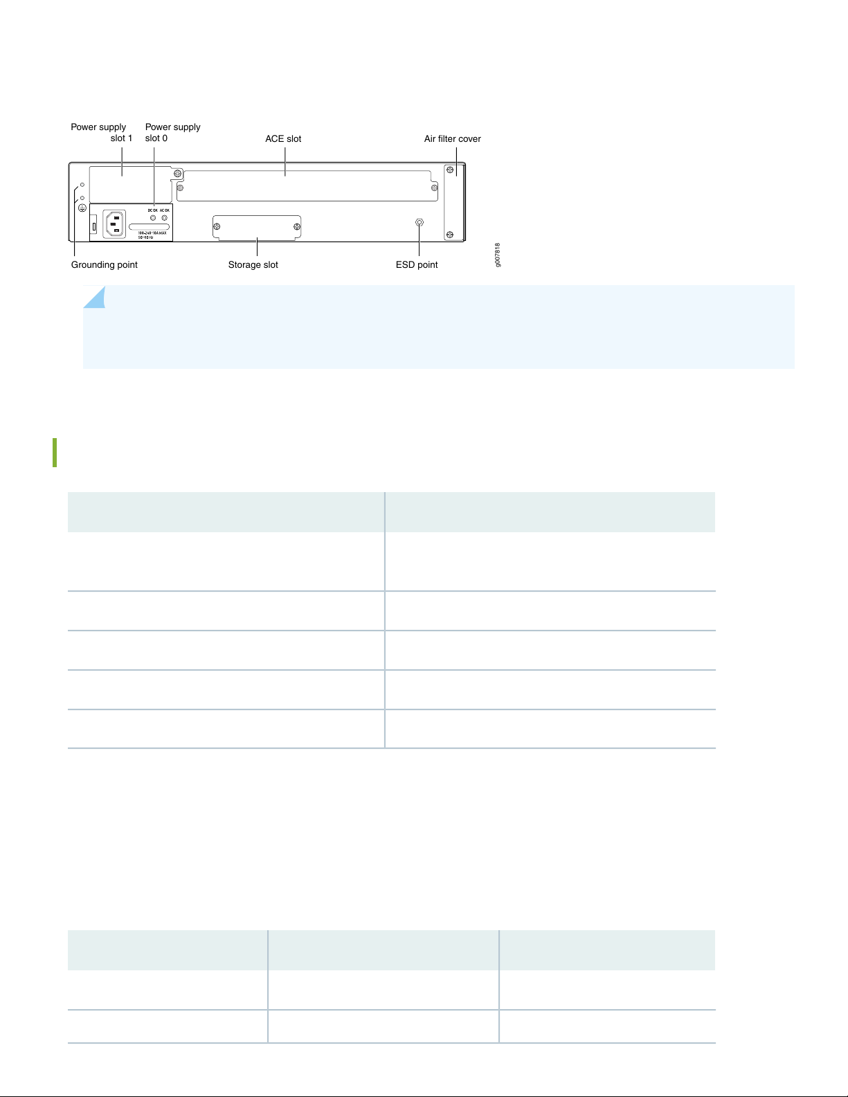
Figure 2: Rear Panel Components
g007818
Power supply
slot 1
Power supply
slot 0
ACE slot
Grounding point
Air filter cover
ESD pointStorage slot
NOTE: Check the parts in the shipment against the items on the packing list. If anything is missing or damaged,
contact your Juniper Networks customer service representative.
Specifications
3
SRX550 HMSpecification
Dimensions (H x W x D)
3.5 in. x 17.5 in. x 18.2 in.
(8.89 cm x 44.45 cm x 46.23 cm)
21.96 lb (9.96 kg)Chassis weight
85 WAverage power consumption
238 BTU/hrAverage heat dissipation
5% to 90%, noncondensingRelative humidity
Factory-Default Settings
The SRX550 High Memory device is shipped with the following factory-default settings:
Table 1: Security Policies
Policy ActionDestination ZoneSource Zone
permittrusttrust
permituntrusttrust
Page 4

Table 2: NAT Rules
Table 3: Ethernet Interfaces
4
Policy ActionDestination ZoneSource Zone
Source NAT to untrust zone interfaceuntrusttrust
IP AddressDHCP StateSecurity ZoneInterfacePort Label
UnassignedClientuntrustge-0/0/0 and ge-0/0/90/0 and 0/9
192.168.1.1/24Servertrustge-0/0/10/1
192.168.2.1/24Servertrustge-0/0/20/2
192.168.3.1/24Servertrustge-0/0/30/3
192.168.4.1/24Servertrustge-0/0/40/4
192.168.5.1/24Servertrustge-0/0/50/5
Table 4: LTE Interfaces
IP AddressSecurity ZoneInterface
N/AN/Acl-1/0/0
ISP assigned*untrustdl0 (logical)
Only if the LTE Mini-PIM is present
The SRX550 High Memory device is shipped with the following services and protocols enabled by default:
Table 5: Services, Protocols, and Startup Mode
Device Startup ModeProtocolsServices
SwitchingRSTP (all interfaces)SSH
HTTPS
NETCONF over SSH
To provide secure traffic, a basic set of screens are configured on the untrust zone.
Page 5

Install the Device in a Rack
Before you begin the installation, review General Safety Guidelines and Warnings. Make sure you have someone available
to help you do the installation. You will need to provide your own rack mount screws and a number two Phillips (+)
screwdriver.
1. Wrap and fasten one end of the electrostatic discharge (ESD) grounding strap around your bare wrist, and connect the
other end to a site ESD point.
2. Position a mounting bracket on each side of the chassis. Use a number two Phillips (+) screwdriver to install the screws
that secure the mounting brackets to the chassis. Use either the front mount position or the center mount position.
Figure 3: Securing the Mounting Brackets (Front-Mount)
5
Figure 4: Securing the Mounting Brackets (Center-Mount)
3. Lift the device and position it in the rack. Line up the bottom hole in each mounting bracket with a hole in each mounting
rail, making sure the device is level.
4. While you are holding the device in place, have a second person insert and tighten the rack mount screws to secure
the mounting brackets to the rack. Make sure to tighten the screws in the two bottom holes first and then tighten the
screws in the two top holes next.
Page 6

Figure 5: Securing the Chassis to the Rack
g009064
6
5. Check that the mounting brackets on each side of the rack are lined up with each other.
Connect the Grounding Cable
1. Attach an ESD strap to an ESD point and place the other end of the strap around your bare wrist.
2. Connect the grounding cable to a proper earth ground. Place the grounding cable lug over the grounding point on the
upper rear of the chassis.
NOTE: The device should be permanently connected to ground during normal operation. A licensed electrician
must attach a cable lug to the grounding cable. A cable with an incorrectly attached lug can damage the
device.
3. Secure the grounding cable lug to the grounding point with the screws.
Page 7

Figure 6: Connecting the Grounding Cable
7
Page 8

Power On the Device
NOTE: Before connecting the device to the power supply, attach an ESD strap to an ESD point and place the
other end of the strap around your bare wrist.
1. If you are using the AC model, perform the following steps:
a. Connect the power supply adapter to the power supply point on the device and to a power source. We recommend
using a surge protector. You must allow the device between five and seven minutes to boot after you power it on.
Figure 7: Connecting the Power Cable
8
b. Secure the power cord to the cable tie holder using a tie-wrap.
2. If you are using the DC model, perform the following steps:
WARNING: Before performing the following procedure, ensure that there is no power in the DC
circuit. To ensure that all power is cut off, locate the circuit breaker on the panel board that services
the DC circuit, switch the circuit breaker to the OFF (0) position, and tape the switch handle of the
circuit breaker in the OFF position.
a. Ensure that the voltage across the DC power source cable leads is 0 V and that the cable leads do not become
active while you are connecting DC power.
b. Verify that the DC power cables are correctly labeled before making connections to the power supply. In a typical
power distribution scheme where the return is connected to chassis ground at the battery plant, you can use a
multimeter to verify the resistance of the -48V and RTN DC cables to chassis ground:
The cable with very high resistance (indicating an open circuit) to chassis ground will be connected to the V-
•
(input) DC power input terminal.
Page 9

The cable with very low resistance (indicating a closed circuit) to chassis ground will be connected to the V+
•
(return) DC power input terminal.
c. Remove the clear plastic cover from the terminal studs on the faceplate.
d. Remove the screws on the terminals by using a Phillips (+) screwdriver, number 2.
e. Secure each positive (+) DC source power cable lug to a RTN (return) terminal. Secure each negative (–) DC source
power cable lug to a -48V (input) terminal.
f. Replace the clear plastic cover over the terminal studs on the faceplate.
g. Remove the tape from the switch handle of the circuit breaker on the panel board that services the DC circuit and
switch the circuit breaker to the ON (|) position.
3. Turn on the power to the AC power receptacle.
4. Note the following LED indications. Wait until the STATUS LED is solid green before proceeding to the next step.
Table 6: LED States
StateLED
9
ALARM
MPIM-1 and MPIM-2
HA
STORAGE
Solid green (receiving power).POWER
•
Solid green (operating normally).STATUS
•
Amber (operating normally–the LED might glow amber if a rescue configuration is
•
not set. This is not a panic condition).
Off (Mini-PIM not present or not detected).
•
Solid green (Mini-PIM is operating normally).
•
Red (Mini-PIM hardware failure or counterfeit check failed).
•
Off (HA not enabled).
•
Solid green (all HA links are available).
•
Solid green (redundant power supply is operating normally).RPS
•
The ACE LED is not functional.ACE
Solid green (the services gateway is transferring data to or from the optional storage
•
device).
Configure Using J-Web
To configure using J-Web:
Page 10

1. Connect any of the network ports numbered 0/1 through 0/5 on the services gateway to the Ethernet port on the
management device, using an RJ-45 cable.
Figure 8: Connecting the Management Device
10
2. Ensure that the management device acquires an IP address. The IP address should be on the corresponding IP subnet
for the interface you connected to in step 1. The device functions as a DHCP server and will assign an IP address to
the management device.
For example, if you are connected to port 0/1, then the IP address of the management device should be from the
192.168.1.x network. If an IP address is not assigned to the management device, manually configure an IP address.
You can use the ipconfig (or ifconfig for Macintosh or Linux users) command to verify the IP address.
NOTE: Do not assign the IP address 192.168.1.1 (if connected to port 0/1) to the management device, as
this IP address is assigned to the SRX550 HM.
Refer to Table 3 for information on the subnet for each interface.
3. Open a browser and type https://192.168.1.1 (if connected to port 0/1). For ports other than 0/1, access the services
gateway using the URL https://192.168.x.1, where x is the port number.
The Phone Home Client screen appears.
Page 11

4. Click Skip to J-Web.
NOTE: To configure the device using zero-touch provisioning (ZTP), see Configure the Device Using ZTP
with Juniper Networks Network Service Controller.
11
5. Set a root authentication password in the Skip to J-Web screen and click Submit.
The J-Web login page appears.
Plug and Play
The SRX550 HM already has factory-default settings configured to make it a plug and play device. So all you have to do
to get the SRX550 HM up and running is connect it to your LAN and WAN networks.
1. Connect the WAN network to port 0/0 to obtain a dynamic IP address.
2. Connect the LAN network to any of the ports from 0/1 through 0/5.
Page 12

3. Check to see if the SRX550 HM is connected to the Internet. Go to http://www.juniper.net. If the page does not load,
check the Internet connection.
After you complete these steps, you can start using the SRX550 HM on your network right away. You can go back and
customize settings at any time. The J-Web Setup wizard is always available to you.
Customize the Basic Configuration with J-Web
You can continue to customize the settings in J-Web. Have these values handy before you begin customizing SRX550
HM settings:
Hostname
•
IP address for the NTP server
•
IP address for the DNS server
•
IP address for the management interface
•
12
NOTE: To customize the configuration in Junos OS Release 15.1X49-D170, see Customize the Configuration
for Junos OS Release 15.1X49-D170.
Log in to J-Web and select the configuration mode that’s right for you. You can then follow the screens as they appear
in the Setup wizard.
Standard—Configure basic security settings for the SRX550 HM.
•
Cluster (HA)—Set up the SRX550 HM in chassis cluster mode.
•
Passive—Set up the SRX550 HM in Tap mode. Tap mode enables the SRX550 HM to passively monitor traffic flows
•
across a network.
Page 13

Next Steps
For information on configuring features on your services gateway, refer to the following:
Junos OS User Guides
•
Getting Started Knowledge Base Article
•
Reference
Technical Support
•
SRX550 High Memory Services Gateway Hardware Guide
•
Supported Transceivers
•
13
Juniper Networks, the Juniper Networks logo, Juniper, and Junos are registered trademarks of Juniper Networks, Inc. in the
United States and other countries. All other trademarks, service marks, registered marks, or registered service marks are the
property of their respective owners. Juniper Networks assumes no responsibility for any inaccuracies in this document. Juniper
Networks reserves the right to change, modify, transfer, or otherwise revise this publication without notice. Copyright © 2020
Juniper Networks, Inc. All rights reserved. Rev. 02, October 2020.
 Loading...