


SRX 3400 and SRX 3600
Services Gateway DC Power Supply
Installation Instructions
February 2009
Part Number: 530-026094-01
Revision 01
This document describes how to install a DC power supply on a Juniper Networks
SRX 3400 or SRX 3600 services gateway.
Contents
DC Power Supply ............................................................................................2
DC Power Supply Electrical Specifications ................................................2
Installing a DC Power Supply ..........................................................................4
Connecting Power to a DC-Powered Services Gateway ....................................6
Preventing Electrostatic Discharge Damage ....................................................9
Electrostatic Discharge Point ...........................................................................9
List of Technical Publications ........................................................................10
Requesting Technical Support .......................................................................11
Revision History ............................................................................................12
■ 1
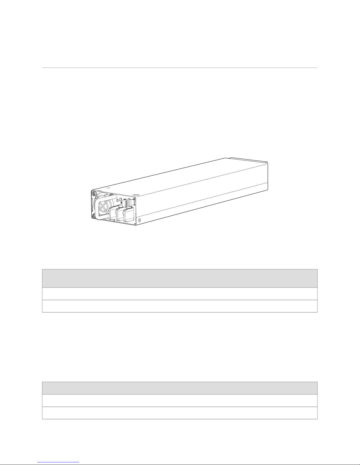
g036076
SRX 3400 and SRX 3600 Services Gateway DC Power Supply Installation Instructions
DC Power Supply
In a DC power configuration, the services gateway contains one to four DC power
supplies, located at the rear of the chassis in slots PEM0 and PEM1 (SRX 3400) or
PEM0 through PEM3 (SRX 3600). Each power supply provides power to all
components in the services gateway. When multiple power supplies are present,
they share power almost equally within a fully populated system. The multiple DC
power supplies provide power redundancy. If one power supply fails or is removed,
the remaining power supplies redistributes the electrical load without interruption.
The device reassesses the power required to support its configuration and issues
errors if the available power is insufficient.
Figure 1: DC Power Supply
Table 1 on page 2 shows the power supply support for the SRX 3400 and SRX 3600
services gateways.
Table 1: Power Supply Support
DC Power Supply Electrical Specifications
Each DC power supply has a single DC input (–48 VDC and return) that requires a
dedicated 40 A (–48 VDC) circuit breaker. Table 2 on page 2 lists the DC power
supply electrical specifications.
Table 2: DC Power Supply Electrical Specifications
SpecificationParameter
850 WMaximum output power
Minimum Number of Power
SuppliesPower Supply SlotsDevice
Maximum Number of Power
Supplies
21PEM0 and PEM1SRX 3400
42PEM0 through PEM4SRX 3600
2 ■ DC Power Supply
–40.5 to –72 VDCDC input voltage
Table 2: DC Power Supply Electrical Specifications (continued)
SpecificationParameter
22.2 A @–48 VDC input current rating
For information about connecting the power supply to DC power, see “Connecting
Power to a DC-Powered Services Gateway” on page 6.
Each DC power supply faceplate displays a single LED to indicate the status of the
power supply (see Table 3 on page 3).
Table 3: DC Power Supply LED
Indicated ConditionLED StatusColor
DC Power Supply
+3V3SB is ON, +12 V
+3V3SB is ON; +12 V
FAN_FAULT, OTP, 3V3 OCP/UVPOn steadilyRed
+12 V_OCP, +12 V_UVP, +12 V OVPBlinking
OUT
OUT
is ONOn steadilyGreen
is OFF; DC is presentBlinking
DC Power Supply ■ 3

SRX 3400 and SRX 3600 Services Gateway DC Power Supply Installation Instructions
Installing a DC Power Supply
To install a DC power supply:
4 ■ Installing a DC Power Supply