

Quick Start Guide
SRX220
IN THIS GUIDE
Step 1: Begin | 1
Step 2: Up and Running | 3
Step 3: Keep Going | 11
Step 1: Begin
IN THIS SECTION
SRX220 Services Gateway Front Panel | 2
SRX220 Services Gateway Back Panel | 2
SRX220 Services Gateway Models | 3
Use the instructions in this quick start to help you connect the SRX220 Services Gateway to your network.
g037618
1
2 3 4 5 6 7 8
1
g037616
1
3 4
21 1
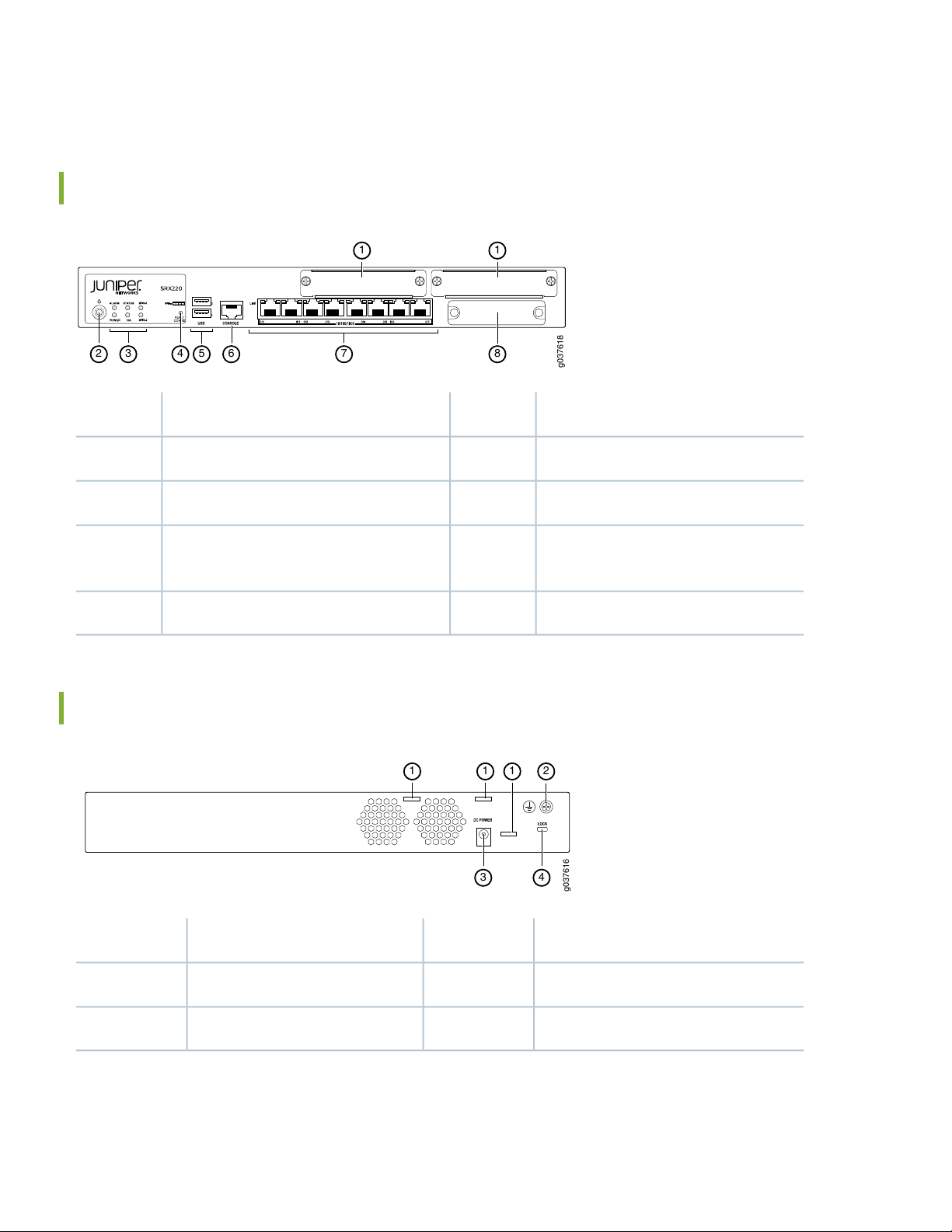
SRX220 Services Gateway Front Panel
DescriptionCalloutDescriptionCallout
Universal Serial Bus (USB) ports5Mini-PIM slot 1 and Mini-PIM slot 21
Console port6Power button2
2
3
MPIM-1, MPIM-2
SRX220 Services Gateway Back Panel
Gigabit Ethernet (0/0 through 0/7) ports7LEDs: STATUS, ALARM, POWER, HA,
CompactFlash card slot8Reset Config button4
DescriptionCalloutDescriptionCallout
Power supply point3Cable tie holder1
Lock slot for security cable4Grounding point2
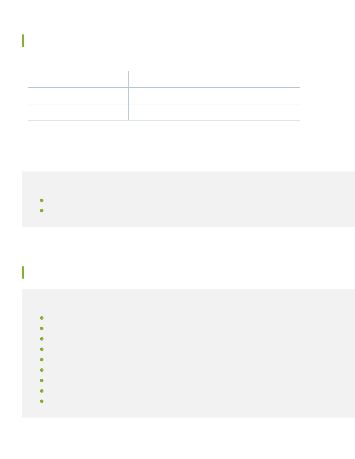
SRX220 Services Gateway Models
The following two models of SRX220 Services Gateways are available::
Power over EthernetDevice
Not supportedSRX220H
120 watts supported across eight ports (0/0 through 0/7)SRX220H-POE
Step 2: Up and Running
IN THIS SECTION
3
Connecting and Configuring the SRX220 Services Gateway | 3
Powering Off the Device | 10
Connecting and Configuring the SRX220 Services Gateway
IN THIS SECTION
Overview | 4
Task 1: Connect the Power Cable to the Device Connect the power supply adapter to the power supply point on the | 5
Task 2: Connect the Management Device | 5
Task 3: Ensure That the Management Device Acquires an IP Address | 6
Task 4: Ensure That an IP Address Is Assigned to the Services Gateway | 6
Task 5: Access the J-Web Interface Setup Wizard | 7
Task 6: Configure the Basic Settings | 8
Task 7: Apply the Basic Configuration | 9
Task 8: Verify the Configuration | 10

Use the instructions below to connect and set up the SRX220 Services Gateway to protect your network. Refer to the
LEDs on the front panel of the device to help you determine the status of the device.
Overview
The SRX220 Services Gateway is a secure routing device that requires these basic configuration settings to function
properly:
Interfaces must be assigned IP addresses.
•
Interfaces must be bound to zones.
•
Policies must be configured between zones to permit/deny traffic.
•
Source NAT rules must be set.
•
The device has the following default configuration set when you power it on for the first time. To be able to use the device,
you do not need to perform any initial configuration.
Factory Default Settings:
IP AddressDHCP StateSecurity ZonesInterfacePort Label
4
0/1 to 0/7
ge-0/0/7
Factory-Default Settings for Security Policies:
Factory-Default Settings for NAT Rules:
unassignedclientuntrustge-0/0/00/0
192.168.1.1/24servertrustge-0/0/1 through
Policy ActionDestination ZoneSource Zone
permituntrusttrust
permittrusttrust
denytrustuntrust
Policy ActionDestination ZoneSource Zone
source NAT to untrust zone interfaceuntrusttrust

Task 1: Connect the Power Cable to the Device Connect the power supply adapter to the power supply point on the
Connect the power supply adapter to the power supply point on the device and to a power source. We recommend using
a surge protector. Secure the connector to the power supply point by wrapping a cable tie around the cable boot and the
adjacent cable tie holder. Note the following indications:
POWER LED (green): The device is receiving power.
•
STATUS LED (green): The device is operating normally.
•
ALARM LED (amber): The device is operating normally, although the LED might be amber because a rescue configuration
•
has not been set yet. This is not a panic condition.
MPIM-1 and MPIM-2 LEDs (off): The Mini-Physical Interface Modules (Mini-PIMs) are not present or are not detected
•
by the device. If these LEDs are solid green, it indicates that the Mini-PIMs are functioning normally.
NOTE: After a rescue configuration has been set, an amber Alarm LED indicates a minor alarm, and a solid red
Alarm LED indicates that a major problem exists on the services gateway.
5
NOTE: You must allow the device between five and seven minutes to boot up after you have powered it on.
Wait until the Status LED is solid green before proceeding to the next task.
Task 2: Connect the Management Device
Connect the management device to the services gateway using either of the following methods:
Connect an RJ-45 cable (Ethernet cable) from any of the ports labeled 0/1 through 0/7 (interfaces ge-0/0/1 through
•
ge-0/0/7) on the front panel to the Ethernet port on the management device (workstation or laptop).
We recommend this connection method. If you are using this method to connect, proceed with Task 4.
Connect an RJ-45 cable (Ethernet cable) from the port labeled CONSOLE to the supplied DB-9 adapter, which then
•
connects to the serial port on the management device. (Serial port settings: 9600 8-N-1.)
NOTE: If you are using this method to connect, proceed with the CLI configuration instructions available in the
Getting Started Guide for the Branch SRX Series at
http://www.juniper.net/techpubs/en_US/junos12.1x46/information-products/
topic-collections/security/software-all/getting-started-guide/ security-getting-started-guide.pdf.
See the illustration below for details on connecting a management interface.

g037614
Task 3: Ensure That the Management Device Acquires an IP Address
After you connect the management device to the services gateway, the DHCP server process on the services gateway
assigns an IP address automatically to the management device. Ensure that the management device acquires an IP address
on the 192.168.1.0/24 subnetwork (other than 192.168.1.1) from the device.
6
NOTE:
The services gateway functions as a DHCP server and will assign an IP address to the management device.
•
If an IP address is not assigned to the management device, manually configure an IP address in the
•
192.168.1.0/24 subnetwork. Do not assign the 192.168.1.1 IP address to the management device, as this IP
address is assigned to the device. By default, the DHCP server is enabled on the L3 VLAN interface, (IRB)
vlan.0 (interfaces ge-0/0/1 through ge-0/0/7), which is configured with an IP address of 192.168.1.1/24.
When an SRX220 Services Gateway is powered on for the first time, it boots using the factory-default
•
configuration.
Task 4: Ensure That an IP Address Is Assigned to the Services Gateway
Use one of the following methods to obtain an IP address for the services gateway:
Method 1: Obtaining a Dynamic IP Address on Your Services Gateway
•
Use the port labeled 0/0 (interface ge-0/0/0) to connect to your Internet Service Provider (ISP). Your ISP will assign an
IP address using the DHCP process.
If you use this method, when you get to Task 7, skip steps 1 through 4.
Method 2: Obtaining a Static IP Address on Your Services Gateway
•
Use the port labeled 0/0 (interface ge-0/0/0) to connect to your Internet Service Provider (ISP). Your ISP will have
provided a static IP address. You will not receive an IP address using the DHCP process.

If you use this method, you must configure the static IP address on the services gateway as described in Task 7, steps
1 through 4.
Task 5: Access the J-Web Interface Setup Wizard
1. Launch a Web browser from the management device.
2. Enter http://192.168.1.1 in the URL address field. The J-Web interface login page opens.
3. Specify the default username as root. Do not enter any value in the Password field.
4. Click Log In. The J-Web Setup Wizard page appears.
7

Task 6: Configure the Basic Settings
Configure the basic settings, such as hostname, domain name, root password, and IP address, for your services gateway.
NOTE: Ensure that you have configured the IP address and root password before you apply the configuration.
NOTE: All fields marked with an asterisk (*) are mandatory.
NOTE: All network and management access settings are optional.
If you have used Method 2 in Task 5 to obtain an IP address on your services gateway, ensure that you make the following
J-Web interface modifications:
8
1. On the Configure System: Network Settings page of the wizard, enter the IP address of the default gateway in the
Default Gateway field and server names in the DNS Name Servers list. Your ISP provides the IP address for the default
gateway and the server names.
2. On the Configure Interfaces page of the wizard, select the ge-0/0/0.0 interface and click Edit.
3. On the Add/Edit interface page, next to Address, unselect DHCP and select IP Address.
4. Next to IP Address/subnet, enter the static IP address provided by your ISP in the IP address/subnet field. The IP
address must be entered in a.b.c.d/xx format, where xx is the subnet prefix.

9
NOTE: NOTE: Make sure that you have selected the required services and protocols under Services (Inbound)
and Protocols (Inbound). Select all to permit all protocols and services.
NOTE: You can use the Configure J-Web Preferences page of the wizard to set J-Web starting page options
and J-Web commit options.
Task 7: Apply the Basic Configuration
On the last page of the wizard (Review and Commit), review the basic configuration and click Commit to save it.
After configuring the basic settings, the J-Web Setup wizard redirects you to J-Web pages where you can continue working
in the J-Web interface.

10
After you complete initial setup configuration, the Setup Wizard is no longer available. To make changes to the configuration,
use the J-Web interface.
NOTE: To make any changes to the interface configuration, see the Getting Started Guide for the Branch SRX
Series at http://www.juniper.net/techpubs/en_US/junos12.1x46/information-products
/topic-collections/security/software-all/getting-started-guide/ security-getting-started-guide.pdf.
Task 8: Verify the Configuration
Access http://www.juniper.net to ensure that you are connected to the Internet. This connectivity ensures that you can
pass traffic through the services gateway.
NOTE: If the http://www.juniper.net page does not load, verify your configuration settings, and ensure that
you have correctly applied the configuration.
After you complete these steps, you can pass traffic from any trust port to the untrust port.
Powering Off the Device
You can power off the device in one of the following ways:
Graceful shutdown—Press and immediately release the Power button. The device begins gracefully shutting down the
•
operating system.
Forced shutdown—Press the Power button and hold it for 10 seconds. The device immediately shuts down. Press the
•
Power button again to power on the device
NOTE: You can reboot or halt the system in the J-Web interface by selecting Maintain > Reboot.
For additional configuration information, see the Getting Started Guide for the Branch SRX Series at
http://www.juniper.net/techpubs/en_US/junos12.1x46/information-products
/topic-collections/security/software-all/getting-started-guide/ security-getting-started-guide.pdf.
For detailed software configuration information, see the software documentation available at
http://www.juniper.net/techpubs/en_US/release-independent/junos/information-products/
pathway-pages/srx-series/product/index.html.

Step 3: Keep Going
IN THIS SECTION
Contacting Juniper Networks | 11
See the complete SRX220 Series documentation at https://www.juniper.net/documentation/product/en_US/srx220.
Contacting Juniper Networks
For technical support, see:
11
http://www.juniper.net/support/requesting-support.html
Juniper Networks, the Juniper Networks logo, Juniper, and Junos are registered trademarks of Juniper Networks, Inc. in the
United States and other countries. All other trademarks, service marks, registered marks, or registered service marks are the
property of their respective owners. Juniper Networks assumes no responsibility for any inaccuracies in this document. Juniper
Networks reserves the right to change, modify, transfer, or otherwise revise this publication without notice. Copyright © 2020
Juniper Networks, Inc. All rights reserved. Rev. 01, June 2020.
 Loading...