


SRX1400 Services Gateway Hardware
Published: 2013-01-02
Copyright © 2013, Juniper Networks, Inc.

Juniper Networks, Inc.
1194 North Mathilda Avenue
Sunnyvale, California 94089
USA
408-745-2000
www.juniper.net
Copyright © 2013, Juniper Networks, Inc. All rights reserved.
Juniper Networks, Junos, Steel-Belted Radius, NetScreen, and ScreenOS are registered trademarks of Juniper Networks, Inc. in the United
States and other countries. The Juniper Networks Logo, the Junos logo, and JunosE are trademarks of Juniper Networks, Inc. All other
trademarks, service marks, registered trademarks, or registered service marks are the property of their respective owners.
Juniper Networks assumes no responsibility for any inaccuracies in this document. Juniper Networks reserves the right to change, modify,
transfer, or otherwise revise this publication without notice.
Products made or sold by Juniper Networks or components thereof might be covered by one or more of the following patents that are
owned by or licensed to Juniper Networks: U.S. Patent Nos. 5,473,599, 5,905,725, 5,909,440, 6,192,051, 6,333,650, 6,359,479, 6,406,312,
6,429,706, 6,459,579, 6,493,347, 6,538,518, 6,538,899, 6,552,918, 6,567,902, 6,578,186, and 6,590,785.
SRX1400 Services Gateway Hardware
Copyright © 2013, Juniper Networks, Inc.
All rights reserved.
The information in this document is current as of the date on the title page.
YEAR 2000 NOTICE
Juniper Networks hardware and software products are Year 2000 compliant. Junos OS has no known time-related limitations through the
year 2038. However, the NTP application is known to have some difficulty in the year 2036.
END USER LICENSE AGREEMENT
The Juniper Networks product that is the subject of this technical documentation consists of (or is intended for use with) Juniper Networks
software. Use of such software is subject to the terms and conditions of the End User License Agreement (“EULA”) posted at
http://www.juniper.net/support/eula.html. By downloading, installing or using such software, you agree to the terms and conditions
of that EULA.
Copyright © 2013, Juniper Networks, Inc.ii

Table of Contents
About the Documentation . . . . . . . . . . . . . . . . . . . . . . . . . . . . . . . . . . . . . . . . . . . . xix
Documentation and Release Notes . . . . . . . . . . . . . . . . . . . . . . . . . . . . . . . . . xix
Supported Platforms . . . . . . . . . . . . . . . . . . . . . . . . . . . . . . . . . . . . . . . . . . . . xix
Documentation Conventions . . . . . . . . . . . . . . . . . . . . . . . . . . . . . . . . . . . . . . xix
Documentation Feedback . . . . . . . . . . . . . . . . . . . . . . . . . . . . . . . . . . . . . . . . xxi
Requesting Technical Support . . . . . . . . . . . . . . . . . . . . . . . . . . . . . . . . . . . . . xxi
Self-Help Online Tools and Resources . . . . . . . . . . . . . . . . . . . . . . . . . . xxii
Opening a Case with JTAC . . . . . . . . . . . . . . . . . . . . . . . . . . . . . . . . . . . . xxii
Part 1 Overview
Chapter 1 Introduction . . . . . . . . . . . . . . . . . . . . . . . . . . . . . . . . . . . . . . . . . . . . . . . . . . . . . . . 3
SRX1400 Services Gateway Description . . . . . . . . . . . . . . . . . . . . . . . . . . . . . . . . . . 3
SRX1400 Services Gateway Models . . . . . . . . . . . . . . . . . . . . . . . . . . . . . . . . . . . . . 4
SRX1400 Services Gateway Hardware Features . . . . . . . . . . . . . . . . . . . . . . . . . . . 4
SRX1400 Services Gateway Physical Specifications . . . . . . . . . . . . . . . . . . . . . . . . 5
SRX1400 Services Gateway Environmental Specifications . . . . . . . . . . . . . . . . . . . 7
Understanding the SRX1400 Services Gateway in the Enterprise Network . . . . . . . 7
Understanding the SRX1400 Services Gateway in the Service Provider
Network . . . . . . . . . . . . . . . . . . . . . . . . . . . . . . . . . . . . . . . . . . . . . . . . . . . . . . . . 8
Understanding the SRX1400 Services Gateway in the Data Center . . . . . . . . . . . . 8
Chapter 2 Hardware Components and Specifications . . . . . . . . . . . . . . . . . . . . . . . . . . . . 11
SRX1400 Services Gateway Chassis Slots . . . . . . . . . . . . . . . . . . . . . . . . . . . . . . . . 11
Overview of the SRX1400 Services Gateway CFMs . . . . . . . . . . . . . . . . . . . . . . . . 12
SRX1400 Services Gateway Hardware Components . . . . . . . . . . . . . . . . . . . . . . . 13
SRX1400 Services Gateway Front Panel . . . . . . . . . . . . . . . . . . . . . . . . . . . . . . . . . 14
SRX1400 Services Gateway Back Panel . . . . . . . . . . . . . . . . . . . . . . . . . . . . . . . . . 15
SRX1400 Services Gateway Backplane . . . . . . . . . . . . . . . . . . . . . . . . . . . . . . . . . . 16
SRX1400 Services Gateway SYSIOCs . . . . . . . . . . . . . . . . . . . . . . . . . . . . . . . . . . . 17
Features and Functions . . . . . . . . . . . . . . . . . . . . . . . . . . . . . . . . . . . . . . . . . . . 18
POWER Button Functionality on the System I/O Card . . . . . . . . . . . . . . . . . . 18
LED Indicators on the System I/O Card . . . . . . . . . . . . . . . . . . . . . . . . . . . . . . 19
Front Panel Ports and Connectors on the System I/O Card . . . . . . . . . . . . . . 22
IOCs and NP-IOCs Supported on the SRX1400 Services Gateway . . . . . . . . . . . . 23
SRX1400 Services Gateway Routing Engine . . . . . . . . . . . . . . . . . . . . . . . . . . . . . . 23
SRX1400 Services Gateway NSPC . . . . . . . . . . . . . . . . . . . . . . . . . . . . . . . . . . . . . 25
SPCs for the SRX1400 Services Gateway . . . . . . . . . . . . . . . . . . . . . . . . . . . . . . . . 26
NPCs for the SRX1400 Services Gateway . . . . . . . . . . . . . . . . . . . . . . . . . . . . . . . . 27
SRX1400 Services Gateway Cooling System . . . . . . . . . . . . . . . . . . . . . . . . . . . . . 28
iiiCopyright © 2013, Juniper Networks, Inc.

SRX1400 Services Gateway Hardware
Chapter 3 Modules Supported By SRX1400, SRX3400, and SRX3600 Services
Chapter 4 Power Supply Units . . . . . . . . . . . . . . . . . . . . . . . . . . . . . . . . . . . . . . . . . . . . . . . 49
Chapter 5 Data Flow . . . . . . . . . . . . . . . . . . . . . . . . . . . . . . . . . . . . . . . . . . . . . . . . . . . . . . . . 55
Gateways . . . . . . . . . . . . . . . . . . . . . . . . . . . . . . . . . . . . . . . . . . . . . . . . . . . . . . . . . 31
SRX1400, SRX3400, and SRX3600 Services Gateway Module Overview . . . . . . 31
Modules Supported on SRX1400, SRX3400, and SRX3600 Services
Gateways . . . . . . . . . . . . . . . . . . . . . . . . . . . . . . . . . . . . . . . . . . . . . . . . . . . . . . 32
Eligible Slots for SRX1400, SRX3400, and SRX3600 Services Gateway
Modules . . . . . . . . . . . . . . . . . . . . . . . . . . . . . . . . . . . . . . . . . . . . . . . . . . . . . . . 33
Hot-Swappable andCold-Swap-Only Modules on the SRX1400, SRX3400, and
SRX3600 Services Gateways . . . . . . . . . . . . . . . . . . . . . . . . . . . . . . . . . . . . . . 35
Services Processing Card SRX3K-SPC-1-10-40 . . . . . . . . . . . . . . . . . . . . . . . . . . . 36
Network Processing Card SRX3K-NPC . . . . . . . . . . . . . . . . . . . . . . . . . . . . . . . . . . 37
I/O Card SRX3K-16GE-TX . . . . . . . . . . . . . . . . . . . . . . . . . . . . . . . . . . . . . . . . . . . . 39
I/O Card SRX3K-16GE-SFP . . . . . . . . . . . . . . . . . . . . . . . . . . . . . . . . . . . . . . . . . . . 40
I/O Card SRX3K-2XGE-XFP . . . . . . . . . . . . . . . . . . . . . . . . . . . . . . . . . . . . . . . . . . . 42
Network Processing I/O Card SRX1K3K-NP-2XGE-SFPP . . . . . . . . . . . . . . . . . . . 44
Routing Engines SRX3K-RE-12-10 and SRX1K-RE-12-10 . . . . . . . . . . . . . . . . . . . . 45
SRX1400 Services Gateway Power Supplies Overview . . . . . . . . . . . . . . . . . . . . . 49
SRX1400 Services Gateway AC Power Supply . . . . . . . . . . . . . . . . . . . . . . . . . . . . 50
AC Power Supply Overview . . . . . . . . . . . . . . . . . . . . . . . . . . . . . . . . . . . . . . . 50
AC Power Supply Electrical Specifications . . . . . . . . . . . . . . . . . . . . . . . . . . . 50
AC Power Supply LEDs . . . . . . . . . . . . . . . . . . . . . . . . . . . . . . . . . . . . . . . . . . . 51
SRX1400 Services Gateway DC Power Supply . . . . . . . . . . . . . . . . . . . . . . . . . . . . 51
DC Power Supply Overview . . . . . . . . . . . . . . . . . . . . . . . . . . . . . . . . . . . . . . . 52
DC Power Supply Electrical Specifications . . . . . . . . . . . . . . . . . . . . . . . . . . . 52
DC Power Supply LEDs . . . . . . . . . . . . . . . . . . . . . . . . . . . . . . . . . . . . . . . . . . . 52
Understanding the SRX1400 Services Gateway Data Flow . . . . . . . . . . . . . . . . . . 55
Part 2 Planning
Chapter 6 Preparing the Site for Installation . . . . . . . . . . . . . . . . . . . . . . . . . . . . . . . . . . . 59
Site Preparation Checklist for the SRX1400 Services Gateway . . . . . . . . . . . . . . . 59
Chapter 7 Cabinet and Rack Requirements . . . . . . . . . . . . . . . . . . . . . . . . . . . . . . . . . . . . 61
SRX1400 Services Gateway Cabinet Requirements . . . . . . . . . . . . . . . . . . . . . . . . 61
Cabinet Size and Clearance Requirements . . . . . . . . . . . . . . . . . . . . . . . . . . . 61
Cabinet Airflow Requirements . . . . . . . . . . . . . . . . . . . . . . . . . . . . . . . . . . . . . 61
SRX1400 Services Gateway Rack Requirements . . . . . . . . . . . . . . . . . . . . . . . . . . 62
SRX1400 Services Gateway Rack Size and Strength Requirements . . . . . . . 62
SRX1400 Services Gateway Spacing of Mounting Bracket Holes . . . . . . . . . 64
Connecting the SRX1400 Services Gateway to the Building Structure . . . . . 64
Clearance Requirements forAirflowand Hardware Maintenance ofthe SRX1400
Services Gateway . . . . . . . . . . . . . . . . . . . . . . . . . . . . . . . . . . . . . . . . . . . . . . . 64
Chapter 8 Grounding Specifications . . . . . . . . . . . . . . . . . . . . . . . . . . . . . . . . . . . . . . . . . . 67
SRX1400 Services Gateway Grounding Cable Specification . . . . . . . . . . . . . . . . . 67
SRX1400 Services Gateway Grounding-Cable Lug Specification . . . . . . . . . . . . . 67
Copyright © 2013, Juniper Networks, Inc.iv

Table of Contents
Chapter 9 AC Power Specifications . . . . . . . . . . . . . . . . . . . . . . . . . . . . . . . . . . . . . . . . . . . 69
SRX1400 Services Gateway Grounding Cable Specification . . . . . . . . . . . . . . . . . 69
SRX1400 Services Gateway Grounding-Cable Lug Specification . . . . . . . . . . . . . 69
Power Requirements for AC-Powered SRX1400 Services Gateways . . . . . . . . . . 70
SRX1400 Services Gateway AC Power Cord Specifications . . . . . . . . . . . . . . . . . . 72
SRX1400 Services Gateway AC Power System Electrical Specifications . . . . . . . 73
SRX1400 Services Gateway AC Power Supply Electrical Specifications . . . . . . . . 74
Chapter 10 DC Power Specifications . . . . . . . . . . . . . . . . . . . . . . . . . . . . . . . . . . . . . . . . . . . 75
SRX1400 Services Gateway DC Power System Electrical Specifications . . . . . . . 75
SRX1400 Services Gateway DC Power Supply Electrical Specifications . . . . . . . . 75
Power Requirements for DC-Powered SRX1400 Services Gateways . . . . . . . . . . . 77
SRX1400 Services Gateway DC Power Cable Specifications . . . . . . . . . . . . . . . . . 78
Chapter 11 Cable and Electrical Wiring Guidelines . . . . . . . . . . . . . . . . . . . . . . . . . . . . . . . 81
SRX1400 Services Gateway Electrical Wiring Guidelines . . . . . . . . . . . . . . . . . . . . 81
Distance Limitations for Signaling for the SRX1400 Services Gateway . . . . . 81
Radio Frequency Interference for the SRX1400 Services Gateway . . . . . . . . . 81
Electromagnetic Compatibility for the SRX1400 Services Gateway . . . . . . . . 81
Console Port Cable and Wire Specifications for the SRX1400 Services
Gateway . . . . . . . . . . . . . . . . . . . . . . . . . . . . . . . . . . . . . . . . . . . . . . . . . . . . . . 82
Part 3 Safety
Chapter 12 Electrical Safety Guidelines and Warnings . . . . . . . . . . . . . . . . . . . . . . . . . . . 85
Signal Loss in Multimode and Single-Mode Fiber-Optic Cable for the SRX1400
Services Gateway . . . . . . . . . . . . . . . . . . . . . . . . . . . . . . . . . . . . . . . . . . . . . . . 85
Calculating the Power Budget for Fiber-Optic Cable for the SRX1400 Services
Gateway . . . . . . . . . . . . . . . . . . . . . . . . . . . . . . . . . . . . . . . . . . . . . . . . . . . . . . 86
Attenuation and Dispersion in Fiber-Optic Cable for the SRX1400 Services
Gateway . . . . . . . . . . . . . . . . . . . . . . . . . . . . . . . . . . . . . . . . . . . . . . . . . . . . . . 86
Calculating the Power Margin for Fiber-Optic Cable for the SRX1400 Services
Gateway . . . . . . . . . . . . . . . . . . . . . . . . . . . . . . . . . . . . . . . . . . . . . . . . . . . . . . 87
Chapter 13 Safety And Regulatory Warnings . . . . . . . . . . . . . . . . . . . . . . . . . . . . . . . . . . . . 91
SRX1400 Services Gateway Definition of Safety Warning Levels . . . . . . . . . . . . . . 91
SRX1400 Services Gateway General Safety Guidelines and Warnings . . . . . . . . . 93
Qualified Personnel Warning . . . . . . . . . . . . . . . . . . . . . . . . . . . . . . . . . . . . . . . . . . 94
Restricted Access Area Warning . . . . . . . . . . . . . . . . . . . . . . . . . . . . . . . . . . . . . . . 95
Preventing Electrostatic Discharge Damage to the SRX1400 Services
Gateway . . . . . . . . . . . . . . . . . . . . . . . . . . . . . . . . . . . . . . . . . . . . . . . . . . . . . . 96
SRX1400 Services Gateway Fire Safety Requirements and Fire Suppression
Equipment . . . . . . . . . . . . . . . . . . . . . . . . . . . . . . . . . . . . . . . . . . . . . . . . . . . . 98
Chassis Lifting Guidelines . . . . . . . . . . . . . . . . . . . . . . . . . . . . . . . . . . . . . . . . . . . . 99
Installation Instructions Warning . . . . . . . . . . . . . . . . . . . . . . . . . . . . . . . . . . . . . . 99
Rack-Mounting Requirements and Warnings . . . . . . . . . . . . . . . . . . . . . . . . . . . . 100
Ramp Warning . . . . . . . . . . . . . . . . . . . . . . . . . . . . . . . . . . . . . . . . . . . . . . . . . . . . 104
vCopyright © 2013, Juniper Networks, Inc.

SRX1400 Services Gateway Hardware
Chapter 14 Laser and LED Safety Guidelines and Warnings . . . . . . . . . . . . . . . . . . . . . . 105
Chapter 15 Maintenance and Operational Safety Guidelines and Warnings . . . . . . . . . 111
Chapter 16 Electrical Safety Guidelines and Warnings . . . . . . . . . . . . . . . . . . . . . . . . . . . 119
Chapter 17 Agency Approval and Compliance Statements for EMC Requirements . . 131
General Laser Safety Guidelines . . . . . . . . . . . . . . . . . . . . . . . . . . . . . . . . . . . . . . 105
Class 1 Laser Product Warning . . . . . . . . . . . . . . . . . . . . . . . . . . . . . . . . . . . . . . . . 106
Class 1 LED Product Warning . . . . . . . . . . . . . . . . . . . . . . . . . . . . . . . . . . . . . . . . . 106
Laser Beam Warning . . . . . . . . . . . . . . . . . . . . . . . . . . . . . . . . . . . . . . . . . . . . . . . . 107
Radiation from Open Port Apertures Warning . . . . . . . . . . . . . . . . . . . . . . . . . . . 108
Battery Handling Warning . . . . . . . . . . . . . . . . . . . . . . . . . . . . . . . . . . . . . . . . . . . . 111
Jewelry Removal Warning . . . . . . . . . . . . . . . . . . . . . . . . . . . . . . . . . . . . . . . . . . . . 112
Lightning Activity Warning . . . . . . . . . . . . . . . . . . . . . . . . . . . . . . . . . . . . . . . . . . . . 114
Product Disposal Warning . . . . . . . . . . . . . . . . . . . . . . . . . . . . . . . . . . . . . . . . . . . . 114
Operating Temperature Warning . . . . . . . . . . . . . . . . . . . . . . . . . . . . . . . . . . . . . . . 115
In Case of Electrical Accident . . . . . . . . . . . . . . . . . . . . . . . . . . . . . . . . . . . . . . . . . 119
DC Power Electrical Safety Guidelines and Warnings . . . . . . . . . . . . . . . . . . . . . . 119
DC Power Electrical Safety Guidelines . . . . . . . . . . . . . . . . . . . . . . . . . . . . . . 119
DC Power Disconnection Warning . . . . . . . . . . . . . . . . . . . . . . . . . . . . . . . . . 120
DC Power Grounding Requirements and Warning . . . . . . . . . . . . . . . . . . . . . 122
DC Power Wiring Sequence Warning . . . . . . . . . . . . . . . . . . . . . . . . . . . . . . . 123
DC Power Wiring Terminations Warning . . . . . . . . . . . . . . . . . . . . . . . . . . . . . 124
General Electrical Safety Guidelines and Warnings . . . . . . . . . . . . . . . . . . . . . . . . 125
Safety Guidelines and Warnings . . . . . . . . . . . . . . . . . . . . . . . . . . . . . . . . . . . 126
Grounded Equipment Warning . . . . . . . . . . . . . . . . . . . . . . . . . . . . . . . . . . . . 126
Backplane Energy Hazard Warning . . . . . . . . . . . . . . . . . . . . . . . . . . . . . . . . . 127
Multiple Power Supplies Disconnection Warning . . . . . . . . . . . . . . . . . . . . . . 127
Power Disconnection Warning . . . . . . . . . . . . . . . . . . . . . . . . . . . . . . . . . . . . 128
TN Power Warning . . . . . . . . . . . . . . . . . . . . . . . . . . . . . . . . . . . . . . . . . . . . . . 129
Copper Conductors Warning . . . . . . . . . . . . . . . . . . . . . . . . . . . . . . . . . . . . . . 129
SRX1400 Services Gateway Compliance Statements for EMC Requirements . . . 131
Canada . . . . . . . . . . . . . . . . . . . . . . . . . . . . . . . . . . . . . . . . . . . . . . . . . . . . . . . 131
European Community . . . . . . . . . . . . . . . . . . . . . . . . . . . . . . . . . . . . . . . . . . . . 131
Japan . . . . . . . . . . . . . . . . . . . . . . . . . . . . . . . . . . . . . . . . . . . . . . . . . . . . . . . . 132
United States . . . . . . . . . . . . . . . . . . . . . . . . . . . . . . . . . . . . . . . . . . . . . . . . . . 132
SRX1400 Services Gateway Agency Approvals . . . . . . . . . . . . . . . . . . . . . . . . . . . 132
SRX1400 Services Gateway NEBS and ETSI Compliance . . . . . . . . . . . . . . . . . . 133
Part 4 Installation
Chapter 18 Installation Overview . . . . . . . . . . . . . . . . . . . . . . . . . . . . . . . . . . . . . . . . . . . . . 137
Installation Overview for the SRX1400 Services Gateway . . . . . . . . . . . . . . . . . . 137
SRX1400 Services Gateway Safety Requirements, Warnings, and Guidelines . . 138
Preparing the SRX1400 Services Gateway for Rack-Mount or Cabinet
Installation . . . . . . . . . . . . . . . . . . . . . . . . . . . . . . . . . . . . . . . . . . . . . . . . . . . . 138
Copyright © 2013, Juniper Networks, Inc.vi

Table of Contents
Chapter 19 Unpacking the Services Gateway . . . . . . . . . . . . . . . . . . . . . . . . . . . . . . . . . . . 141
Required Tools and Parts for Unpacking the SRX1400 Services Gateway . . . . . . 141
Unpacking the SRX1400 Services Gateway . . . . . . . . . . . . . . . . . . . . . . . . . . . . . . 141
Verifying Parts Received with the SRX1400 Services Gateway . . . . . . . . . . . . . . 143
Chapter 20 Installing the Services Gateway Using a Mechanical Lift . . . . . . . . . . . . . . . 145
Required Tools for Installing the SRX1400 Services Gateway . . . . . . . . . . . . . . . 145
Installing the Mounting Hardware for the SRX1400 Services Gateway . . . . . . . . 145
Installing theSRX1400 Services Gatewayin aRack orCabinet Using a Mechanical
Lift . . . . . . . . . . . . . . . . . . . . . . . . . . . . . . . . . . . . . . . . . . . . . . . . . . . . . . . . . . 146
Chapter 21 Installing the Services Gateway Manually (Without a Mechanical Lift) . . 151
Installing the SRX1400 Services Gateway in a Rack or Cabinet Manually . . . . . . 151
Required Tools for Installing the SRX1400 Services Gateway Manually . . . . . . . 152
Removing Components from the Chassis for Manual Lifting of the SRX1400
Services Gateway . . . . . . . . . . . . . . . . . . . . . . . . . . . . . . . . . . . . . . . . . . . . . . 153
Lifting the SRX1400 Services Gateway Chassis into a Rack . . . . . . . . . . . . . . . . . 153
Reinstalling Components into the SRX1400 Services Gateway Chassis . . . . . . . 155
Chapter 22 Installing Additional Hardware Components . . . . . . . . . . . . . . . . . . . . . . . . . 157
Installing a Network and Services Processing Card in an SRX1400 Services
Gateway . . . . . . . . . . . . . . . . . . . . . . . . . . . . . . . . . . . . . . . . . . . . . . . . . . . . . . 157
Installing an SPC in an SRX1400 Services Gateway . . . . . . . . . . . . . . . . . . . . . . . 159
Installing an NPC in an SRX1400 Services Gateway . . . . . . . . . . . . . . . . . . . . . . . 161
Installing an IOC or NP-IOC in an SRX1400 Services Gateway . . . . . . . . . . . . . . . 163
Installing a System I/O Card into the SRX1400 Services Gateway . . . . . . . . . . . 165
Installing an AC Power Supply in the SRX1400 Services Gateway . . . . . . . . . . . 166
Installing a DC Power Supply in the SRX1400 Services Gateway . . . . . . . . . . . . . 167
Chapter 23 Grounding, Powering On, and Powering Off the Services Gateway . . . . . . 169
Required Tools and Parts for Grounding and Providing Power to the SRX1400
Services Gateway . . . . . . . . . . . . . . . . . . . . . . . . . . . . . . . . . . . . . . . . . . . . . . 169
SRX1400 Services Gateway Chassis Grounding Point . . . . . . . . . . . . . . . . . . . . . 169
Grounding the SRX1400 Services Gateway . . . . . . . . . . . . . . . . . . . . . . . . . . . . . . 170
Connecting the SRX1400 Services Gateway to an AC Power Supply . . . . . . . . . . 171
Connecting the SRX1400 Services Gateway to a DC Power Supply . . . . . . . . . . . 173
Powering On the SRX1400 Services Gateway . . . . . . . . . . . . . . . . . . . . . . . . . . . . 174
Powering Off the SRX1400 Services Gateway . . . . . . . . . . . . . . . . . . . . . . . . . . . . 175
Part 5 Configuration
Chapter 24 Connecting the Services Gateway to the Network . . . . . . . . . . . . . . . . . . . . 179
Connecting the SRX1400 Services Gateway to a Management Console or an
Connecting the SRX1400 Services Gateway to a Network for Out-of-Band
Chapter 25 Configuring Basic Settings . . . . . . . . . . . . . . . . . . . . . . . . . . . . . . . . . . . . . . . . . 181
SRX1400 Services Gateway Software Configuration Overview . . . . . . . . . . . . . . 181
Performing Initial Software Configuration on the SRX1400 Services Gateway
Auxiliary Device . . . . . . . . . . . . . . . . . . . . . . . . . . . . . . . . . . . . . . . . . . . . . . . . 179
Management . . . . . . . . . . . . . . . . . . . . . . . . . . . . . . . . . . . . . . . . . . . . . . . . . . 180
(CLI Procedure) . . . . . . . . . . . . . . . . . . . . . . . . . . . . . . . . . . . . . . . . . . . . . . . . 182
viiCopyright © 2013, Juniper Networks, Inc.

SRX1400 Services Gateway Hardware
Part 6 Maintenance
Chapter 26 Maintaining the Hardware . . . . . . . . . . . . . . . . . . . . . . . . . . . . . . . . . . . . . . . . . 189
Chapter 27 Replacing Hardware Components . . . . . . . . . . . . . . . . . . . . . . . . . . . . . . . . . . 195
Chapter 28 Replacing Cooling System Components . . . . . . . . . . . . . . . . . . . . . . . . . . . . 199
Chapter 29 Replacing Host Subsystem Components . . . . . . . . . . . . . . . . . . . . . . . . . . . 205
Chapter 30 Replacing Power Supply Components . . . . . . . . . . . . . . . . . . . . . . . . . . . . . . 221
Required Tools and Parts for Maintaining the SRX1400 Services Gateway
Hardware Components . . . . . . . . . . . . . . . . . . . . . . . . . . . . . . . . . . . . . . . . . . 189
Routine Maintenance Procedures for the SRX1400 Services Gateway . . . . . . . . 189
Maintaining the Air Filter on the SRX1400 Services Gateway . . . . . . . . . . . . . . . 190
Maintaining the Fan Tray on the SRX1400 Services Gateway . . . . . . . . . . . . . . . 190
Maintaining the Routing Engine on the SRX1400 Services Gateway . . . . . . . . . . 191
Maintaining Power Supplies on the SRX1400 Services Gateway . . . . . . . . . . . . . 192
Required Tools and Partsfor Replacing Hardware Components on the SRX1400
Services Gateway . . . . . . . . . . . . . . . . . . . . . . . . . . . . . . . . . . . . . . . . . . . . . . 195
Field-Replaceable Units on the SRX1400 Services Gateway . . . . . . . . . . . . . . . . 196
Replacing the Cooling System Air Filter on the SRX1400 Services Gateway . . . . 199
Replacing the Fan Tray on the SRX1400 Services Gateway . . . . . . . . . . . . . . . . . 201
Replacing a Routing Engine on the SRX1400 Services Gateway . . . . . . . . . . . . . 205
Replacing an IOC or NP-IOC on the SRX1400 Services Gateway . . . . . . . . . . . . 207
Replacing a Network and Services Processing Card on the SRX1400 Services
Gateway . . . . . . . . . . . . . . . . . . . . . . . . . . . . . . . . . . . . . . . . . . . . . . . . . . . . . . 210
Replacing the SYSIOC on the SRX1400 Services Gateway . . . . . . . . . . . . . . . . . . 212
Replacing SFP, SFP+, and XFP Transceivers on the SRX1400 Services
Gateway . . . . . . . . . . . . . . . . . . . . . . . . . . . . . . . . . . . . . . . . . . . . . . . . . . . . . . 214
Replacing a Network Processing Card on the SRX1400 Services Gateway . . . . . 217
Replacing an SPC on the SRX1400 Services Gateway . . . . . . . . . . . . . . . . . . . . . 218
Replacing AC Power Supply Cables on the SRX1400 Services Gateway . . . . . . . 221
Replacing an AC Power Supply on the SRX1400 Services Gateway . . . . . . . . . . 222
Replacing a DC Power Supply on the SRX1400 Services Gateway . . . . . . . . . . . 225
Replacing DC Power Supply Cables on the SRX1400 Services Gateway . . . . . . 228
Replacing the Power Supply Air Filter on the SRX1400 Services Gateway . . . . . 229
Part 7 Troubleshooting
Chapter 31 Troubleshooting Hardware Components . . . . . . . . . . . . . . . . . . . . . . . . . . . . 235
Troubleshooting with the CLI on the SRX1400 Services Gateway . . . . . . . . . . . . 235
Troubleshooting with LEDs on the SRX1400 Services Gateway . . . . . . . . . . . . . 237
Troubleshooting with Chassis and Interface Alarm Messages on the SRX1400
Troubleshooting the Power System on the SRX1400 Services Gateway . . . . . . 239
Troubleshooting the Cooling System on the SRX1400 Services Gateway . . . . . . 241
Troubleshooting the System I/O Card on the SRX1400 Services Gateway . . . . . 242
Troubleshooting the Network and Services Processing Card on the SRX1400
Troubleshooting I/O Cards on the SRX1400 Services Gateway . . . . . . . . . . . . . 244
Services Gateway . . . . . . . . . . . . . . . . . . . . . . . . . . . . . . . . . . . . . . . . . . . . . . 239
Services Gateway . . . . . . . . . . . . . . . . . . . . . . . . . . . . . . . . . . . . . . . . . . . . . . 243
Copyright © 2013, Juniper Networks, Inc.viii

Table of Contents
Troubleshooting an NPC on the SRX1400 Services Gateway . . . . . . . . . . . . . . . 244
Troubleshooting Services Processing Cards on the SRX1400 Services
Gateway . . . . . . . . . . . . . . . . . . . . . . . . . . . . . . . . . . . . . . . . . . . . . . . . . . . . . 245
Chapter 32 Juniper Networks Technical Assistance Center . . . . . . . . . . . . . . . . . . . . . . . 247
Juniper Networks Technical Assistance Center . . . . . . . . . . . . . . . . . . . . . . . . . . . 247
Chapter 33 Returning the Services Gateway . . . . . . . . . . . . . . . . . . . . . . . . . . . . . . . . . . . 249
Return Procedure for the SRX1400 Services Gateway . . . . . . . . . . . . . . . . . . . . . 249
Listing the SRX1400 Services Gateway Component Serial Numbers with the
CLI . . . . . . . . . . . . . . . . . . . . . . . . . . . . . . . . . . . . . . . . . . . . . . . . . . . . . . . . . . 250
Chapter 34 Contacting Customer Support . . . . . . . . . . . . . . . . . . . . . . . . . . . . . . . . . . . . . 253
Information You Might Need to Supply to JTAC . . . . . . . . . . . . . . . . . . . . . . . . . . 253
Contacting Customer Support . . . . . . . . . . . . . . . . . . . . . . . . . . . . . . . . . . . . . . . 253
Chapter 35 Locating Component Serial Numbers . . . . . . . . . . . . . . . . . . . . . . . . . . . . . . . 255
Locating the SRX1400 Services Gateway Chassis Serial Number Label . . . . . . . 255
Locatingthe SRX1400Services Gateway Network andServices Processing Card
Serial Number Label . . . . . . . . . . . . . . . . . . . . . . . . . . . . . . . . . . . . . . . . . . . . 256
Locating the SRX1400 Services Gateway System I/O Card Serial Number
Label . . . . . . . . . . . . . . . . . . . . . . . . . . . . . . . . . . . . . . . . . . . . . . . . . . . . . . . . 256
Locating the SRX1400 Services Gateway Power Supply Serial Number Label . . 257
Locating the SRX1400 Services Gateway Fan Tray Number Label . . . . . . . . . . . 257
Chapter 36 Packing Components for Shipment . . . . . . . . . . . . . . . . . . . . . . . . . . . . . . . . 259
Required Tools and Parts for Packing the SRX1400 Services Gateway . . . . . . . . 259
Packing the SRX1400 Services Gateway for Shipment . . . . . . . . . . . . . . . . . . . . 259
Packing SRX1400 Services Gateway Components for Shipment . . . . . . . . . . . . 260
Part 8 Index
Index . . . . . . . . . . . . . . . . . . . . . . . . . . . . . . . . . . . . . . . . . . . . . . . . . . . . . . . . 265
ixCopyright © 2013, Juniper Networks, Inc.

SRX1400 Services Gateway Hardware
Copyright © 2013, Juniper Networks, Inc.x

List of Figures
Part 1 Overview
Chapter 1 Introduction . . . . . . . . . . . . . . . . . . . . . . . . . . . . . . . . . . . . . . . . . . . . . . . . . . . . . . . 3
Figure 1: SRX1400 Services Gateway Chassis . . . . . . . . . . . . . . . . . . . . . . . . . . . . . . 6
Chapter 2 Hardware Components and Specifications . . . . . . . . . . . . . . . . . . . . . . . . . . . . 11
Figure 2: SRX1400 Services Gateway Front Panel Slot Label Guide . . . . . . . . . . . . 12
Figure 3: SRX1400 Services Gateway Front Panel . . . . . . . . . . . . . . . . . . . . . . . . . . 15
Figure 4: SRX1400 Services Gateway Back Panel . . . . . . . . . . . . . . . . . . . . . . . . . . 16
Figure 5: SRX1400 Services Gateway Backplane . . . . . . . . . . . . . . . . . . . . . . . . . . 16
Figure 6: SRX1400 Services Gateway 1-Gigabit Ethernet SYSIOC . . . . . . . . . . . . . 18
Figure 7: SRX1400 Services Gateway 10-Gigabit Ethernet SYSIOC . . . . . . . . . . . . 18
Figure 8: SRX1400 Services Gateway SYSIOC LEDs . . . . . . . . . . . . . . . . . . . . . . . . 19
Figure 9: SRX1400 Services Gateway Routing Engine . . . . . . . . . . . . . . . . . . . . . . 24
Figure 10: SRX1400 Services Gateway Routing Engine . . . . . . . . . . . . . . . . . . . . . 24
Figure 11: SRX1400 Services Gateway Network and Services Processing Card . . . 25
Figure 12: Services Processing Card . . . . . . . . . . . . . . . . . . . . . . . . . . . . . . . . . . . . . 27
Figure 13: Network Processing Card . . . . . . . . . . . . . . . . . . . . . . . . . . . . . . . . . . . . . 28
Figure 14: SRX1400 Services Gateway Fan Tray . . . . . . . . . . . . . . . . . . . . . . . . . . . 29
Chapter 3 Modules Supported By SRX1400, SRX3400, and SRX3600 Services
Gateways . . . . . . . . . . . . . . . . . . . . . . . . . . . . . . . . . . . . . . . . . . . . . . . . . . . . . . . . . 31
Figure 15: SRX3K-SPC-1-10-40 SPC . . . . . . . . . . . . . . . . . . . . . . . . . . . . . . . . . . . . 36
Figure 16: SPC Serial Number Label . . . . . . . . . . . . . . . . . . . . . . . . . . . . . . . . . . . . 37
Figure 17: Network Processing Card SRX3K-NPC . . . . . . . . . . . . . . . . . . . . . . . . . . 38
Figure 18: NPC Serial Number Label . . . . . . . . . . . . . . . . . . . . . . . . . . . . . . . . . . . . 38
Figure 19: 16-Port Copper 10/100/1000 IOC . . . . . . . . . . . . . . . . . . . . . . . . . . . . . . 39
Figure 20: IOC Serial Number Label (SRX3K-16GE-TX Shown, Other IOCs
Similar) . . . . . . . . . . . . . . . . . . . . . . . . . . . . . . . . . . . . . . . . . . . . . . . . . . . . . . . 40
Figure 21: 16-Port SFP Gigabit Ethernet IOC . . . . . . . . . . . . . . . . . . . . . . . . . . . . . . 41
Figure 22: IOC Serial Number Label (SRX3K-16GE-TX Shown, Other IOCs
Similar) . . . . . . . . . . . . . . . . . . . . . . . . . . . . . . . . . . . . . . . . . . . . . . . . . . . . . . . 42
Figure 23: 2-Port XFP 10-Gigabit Ethernet IOC . . . . . . . . . . . . . . . . . . . . . . . . . . . . 42
Figure 24: IOC Serial Number Label (SRX3K-16GE-TX Shown, Other IOCs
Similar) . . . . . . . . . . . . . . . . . . . . . . . . . . . . . . . . . . . . . . . . . . . . . . . . . . . . . . . 43
Figure 25: NP-IOC SRX1K3K-NP-2XGE-SFPP . . . . . . . . . . . . . . . . . . . . . . . . . . . . 44
Figure 26: IOC Serial Number Label (SRX3K-16GE-TX Shown, Other IOCs
Similar) . . . . . . . . . . . . . . . . . . . . . . . . . . . . . . . . . . . . . . . . . . . . . . . . . . . . . . . 45
Figure 27: Routing Engine (SRX3K-RE-12-10 Shown, SRX1K-RE-12-10
Similar) . . . . . . . . . . . . . . . . . . . . . . . . . . . . . . . . . . . . . . . . . . . . . . . . . . . . . . . 46
Figure 28: Routing Engine Serial Number Label . . . . . . . . . . . . . . . . . . . . . . . . . . . 47
xiCopyright © 2013, Juniper Networks, Inc.

SRX1400 Services Gateway Hardware
Chapter 4 Power Supply Units . . . . . . . . . . . . . . . . . . . . . . . . . . . . . . . . . . . . . . . . . . . . . . . 49
Chapter 5 Data Flow . . . . . . . . . . . . . . . . . . . . . . . . . . . . . . . . . . . . . . . . . . . . . . . . . . . . . . . . 55
Part 2 Planning
Chapter 7 Cabinet and Rack Requirements . . . . . . . . . . . . . . . . . . . . . . . . . . . . . . . . . . . . 61
Chapter 8 Grounding Specifications . . . . . . . . . . . . . . . . . . . . . . . . . . . . . . . . . . . . . . . . . . 67
Chapter 9 AC Power Specifications . . . . . . . . . . . . . . . . . . . . . . . . . . . . . . . . . . . . . . . . . . . 69
Part 3 Safety
Figure 29: SRX1400 Services Gateway AC Power Supply . . . . . . . . . . . . . . . . . . . 50
Figure 30: SRX1400 Services Gateway Data Flow . . . . . . . . . . . . . . . . . . . . . . . . . 55
Figure 31: Typical Open-Frame Rack . . . . . . . . . . . . . . . . . . . . . . . . . . . . . . . . . . . . 63
Figure 32: SRX1400 Services Gateway Clearance Requirements . . . . . . . . . . . . . 65
Figure 33: Grounding Cable Lug . . . . . . . . . . . . . . . . . . . . . . . . . . . . . . . . . . . . . . . . 67
Figure 34: Grounding Cable Lug . . . . . . . . . . . . . . . . . . . . . . . . . . . . . . . . . . . . . . . . 70
Figure 35: AC Plug Types . . . . . . . . . . . . . . . . . . . . . . . . . . . . . . . . . . . . . . . . . . . . . 73
Chapter 13 Safety And Regulatory Warnings . . . . . . . . . . . . . . . . . . . . . . . . . . . . . . . . . . . . 91
Figure 36: ESD Point on the SRX1400 Services Gateway . . . . . . . . . . . . . . . . . . . . 97
Figure 37: Placing a Component into an Electrostatic Bag . . . . . . . . . . . . . . . . . . . 97
Part 4 Installation
Chapter 19 Unpacking the Services Gateway . . . . . . . . . . . . . . . . . . . . . . . . . . . . . . . . . . . 141
Figure 38: Unpack the SRX1400 Services Gateway . . . . . . . . . . . . . . . . . . . . . . . 142
Chapter 20 Installing the Services Gateway Using a Mechanical Lift . . . . . . . . . . . . . . . 145
Figure 39: Attaching Mounting Brackets to the SRX1400 Services Gateway . . . . 146
Figure 40: Load SRX1400 Services Gateway Into a Mechanical Lift . . . . . . . . . . . 147
Figure 41: Attach Mounting Hardware for Two-Post Rack . . . . . . . . . . . . . . . . . . 148
Chapter 21 Installing the Services Gateway Manually (Without a Mechanical Lift) . . 151
Figure 42: Lift the Chassis Into the Rack . . . . . . . . . . . . . . . . . . . . . . . . . . . . . . . . 154
Figure 43: Attach Mounting Hardware for Two-Post Rack . . . . . . . . . . . . . . . . . . 154
Chapter 22 Installing Additional Hardware Components . . . . . . . . . . . . . . . . . . . . . . . . . 157
Figure 44: SRX1400 Services Gateway with CFM Slots 1 and 3 Covered by
Double-Wide Filler Cover . . . . . . . . . . . . . . . . . . . . . . . . . . . . . . . . . . . . . . . . 158
Figure 45: Installing a Network and Services Processing Card in an SRX1400
Services Gateway . . . . . . . . . . . . . . . . . . . . . . . . . . . . . . . . . . . . . . . . . . . . . . 159
Figure 46: Installing Double-Wide Tray on SRX1400 Services Gateway . . . . . . . 160
Figure 47: Installing an SPC in Slot 1 of the SRX1400 Services Gateway . . . . . . . 160
Figure 48: Installing an SPC in Slot 2 of the SRX1400 Services Gateway . . . . . . . 161
Figure 49: Installing a Double-Wide Tray on the SRX1400 Services Gateway . . . 162
Figure 50: Installing an NPC on the SRX1400 Services Gateway . . . . . . . . . . . . . 162
Figure 51: Installing an AC Power Supply in the SRX1400 Services Gateway . . . 166
Figure 52: Installing a DC Power Supply in the SRX1400 Services Gateway . . . . 167
Chapter 23 Grounding, Powering On, and Powering Off the Services Gateway . . . . . . 169
Copyright © 2013, Juniper Networks, Inc.xii

List of Figures
Figure 53: Grounding Point on the SRX1400 Services Gateway . . . . . . . . . . . . . . 170
Figure 54: Connect the Grounding Cable to the SRX1400 Services Gateway . . . . 171
Figure 55: Connect the Chassis to AC Power . . . . . . . . . . . . . . . . . . . . . . . . . . . . . 172
Part 5 Configuration
Chapter 24 Connecting the Services Gateway to the Network . . . . . . . . . . . . . . . . . . . . 179
Figure 56: Console Cable Connector . . . . . . . . . . . . . . . . . . . . . . . . . . . . . . . . . . . 179
Figure 57: Ethernet Cable Connector . . . . . . . . . . . . . . . . . . . . . . . . . . . . . . . . . . . 180
Part 6 Maintenance
Chapter 28 Replacing Cooling System Components . . . . . . . . . . . . . . . . . . . . . . . . . . . . 199
Figure 58: Removing the Cooling System Air Filter from the SRX1400 Services
Gateway . . . . . . . . . . . . . . . . . . . . . . . . . . . . . . . . . . . . . . . . . . . . . . . . . . . . . 200
Figure 59: Installing Cooling System Air Filter from the SRX1400 Services
Gateway . . . . . . . . . . . . . . . . . . . . . . . . . . . . . . . . . . . . . . . . . . . . . . . . . . . . . 200
Figure 60: Replacing the Fan Tray—Opening the Fan Tray Door . . . . . . . . . . . . . 202
Figure 61: Removing the Fan Tray from the SRX1400 Services Gateway . . . . . . 202
Figure 62: Installing the Fan Tray into the SRX1400 Services Gateway . . . . . . . . 203
Chapter 29 Replacing Host Subsystem Components . . . . . . . . . . . . . . . . . . . . . . . . . . . 205
Figure 63: Removing the Routing Engine from the SRX1400 Services
Gateway . . . . . . . . . . . . . . . . . . . . . . . . . . . . . . . . . . . . . . . . . . . . . . . . . . . . . 206
Figure 64: Installing the Routing Engine on the SRX1400 Services Gateway . . . 206
Figure 65: Removing an IOC or NP-IOC from the SRX1400 Services Gateway . . 209
Figure 66: Installing an IOC or NP-IOC on the SRX1400 Services Gateway . . . . 209
Figure 67: Removing the NSPC from the SRX1400 Services Gateway . . . . . . . . . 211
Figure 68: Installing the NSPC in the SRX1400 Services Gateway . . . . . . . . . . . . 212
Figure 69: Removing the SYSIOC from the SRX1400 Services Gateway . . . . . . . 213
Figure 70: Installing the SYSIOC from the SRX1400 Services Gateway . . . . . . . . 213
Figure 71: Removing SFP, SFP+, or XFP Transceivers . . . . . . . . . . . . . . . . . . . . . . 216
Figure 72: Removing an NPC from the SRX1400 Services Gateway . . . . . . . . . . . 217
Figure 73: Installing an NPC on the SRX1400 Services Gateway . . . . . . . . . . . . . 218
Figure 74: Removing an SPC from the SRX1400 Services Gateway . . . . . . . . . . . 219
Figure 75: Installing an SPC on the SRX1400 Services Gateway . . . . . . . . . . . . . 220
Chapter 30 Replacing Power Supply Components . . . . . . . . . . . . . . . . . . . . . . . . . . . . . . 221
Figure 76: Connecting AC Power Supply Cables on the SRX1400 Services
Gateway . . . . . . . . . . . . . . . . . . . . . . . . . . . . . . . . . . . . . . . . . . . . . . . . . . . . . . 222
Figure 77: Removing an AC Power Supply from the SRX1400 Services
Gateway . . . . . . . . . . . . . . . . . . . . . . . . . . . . . . . . . . . . . . . . . . . . . . . . . . . . . . 223
Figure 78: Installing an AC Power Supply in the SRX1400 Services Gateway . . . 223
Figure 79: Removing a DC Power Supply from the SRX1400 Services
Gateway . . . . . . . . . . . . . . . . . . . . . . . . . . . . . . . . . . . . . . . . . . . . . . . . . . . . . 225
Figure 80: Installing a DC Power Supply on the SRX1400 Services Gateway . . . 226
Figure 81: Typical DC Source Cabling to the SRX1400 Services Gateway . . . . . . 227
Figure 82: SRX1400 Power Supply Air Filter . . . . . . . . . . . . . . . . . . . . . . . . . . . . . 230
xiiiCopyright © 2013, Juniper Networks, Inc.

SRX1400 Services Gateway Hardware
Part 7 Troubleshooting
Chapter 35 Locating Component Serial Numbers . . . . . . . . . . . . . . . . . . . . . . . . . . . . . . . 255
Figure 83: SRX1400 Services Gateway Chassis Serial Number Label . . . . . . . . . 255
Figure 84: SRX1400 Services Gateway Network and Services Processing Card
Serial Number Label . . . . . . . . . . . . . . . . . . . . . . . . . . . . . . . . . . . . . . . . . . . . 256
Figure 85: Locating the SRX1400 Services Gateway System I/O Card Serial
Number Label . . . . . . . . . . . . . . . . . . . . . . . . . . . . . . . . . . . . . . . . . . . . . . . . . 256
Figure 86: SRX1400 Services Gateway Power Supply Serial Number Label . . . . 257
Figure 87: SRX1400 Fan Tray . . . . . . . . . . . . . . . . . . . . . . . . . . . . . . . . . . . . . . . . . 257
Copyright © 2013, Juniper Networks, Inc.xiv

List of Tables
About the Documentation . . . . . . . . . . . . . . . . . . . . . . . . . . . . . . . . . . . . . . . . . xix
Table 1: Notice Icons . . . . . . . . . . . . . . . . . . . . . . . . . . . . . . . . . . . . . . . . . . . . . . . . . xx
Table 2: Text and Syntax Conventions . . . . . . . . . . . . . . . . . . . . . . . . . . . . . . . . . . . xx
Part 1 Overview
Chapter 1 Introduction . . . . . . . . . . . . . . . . . . . . . . . . . . . . . . . . . . . . . . . . . . . . . . . . . . . . . . . 3
Table 3: SRX1400 Services Gateway Models . . . . . . . . . . . . . . . . . . . . . . . . . . . . . . 4
Table 4: SRX1400 Services Gateway Hardware Features . . . . . . . . . . . . . . . . . . . . 5
Table 5: SRX1400 Services Gateway Physical Specifications . . . . . . . . . . . . . . . . . 6
Table 6: Weight of the SRX1400 Services Gateway with Different
Table 7: SRX1400 Services Gateway Environmental Specifications . . . . . . . . . . . . 7
Chapter 2 Hardware Components and Specifications . . . . . . . . . . . . . . . . . . . . . . . . . . . . 11
Table 8: SRX1400 Services Gateway Chassis Slots . . . . . . . . . . . . . . . . . . . . . . . . . 12
Table 9: SRX1400 Services Gateway Hardware Components . . . . . . . . . . . . . . . . 13
Table 10: SRX1400 Services Gateway Minimal Configuration . . . . . . . . . . . . . . . . 14
Table 11: SRX1400 Services Gateway Components on the Front Panel . . . . . . . . . 15
Table 12: SRX1400 Services Gateway Components on the Back Panel . . . . . . . . . 16
Table 13: SRX1400 Services Gateway System I/O Card Models . . . . . . . . . . . . . . . 17
Table 14: Power Button Behavior . . . . . . . . . . . . . . . . . . . . . . . . . . . . . . . . . . . . . . . 19
Table 15: System I/O Card LED Indicators . . . . . . . . . . . . . . . . . . . . . . . . . . . . . . . . 19
Table 16: SRX1400 Services Gateway Ethernet Port LEDs . . . . . . . . . . . . . . . . . . . 22
Table 17: System I/O Card Front Panel Ports and Connectors . . . . . . . . . . . . . . . . 22
Table 18: SRX1400 Services Gateway Network and Services Processing Card
Table 19: Fan Tray LED . . . . . . . . . . . . . . . . . . . . . . . . . . . . . . . . . . . . . . . . . . . . . . . 29
Chapter 3 Modules Supported By SRX1400, SRX3400, and SRX3600 Services
Gateways . . . . . . . . . . . . . . . . . . . . . . . . . . . . . . . . . . . . . . . . . . . . . . . . . . . . . . . . . 31
Table 20: Supported Modules for SRX1400, SRX3400, and SRX3600 Services
Table 21: Supported Slots for SRX1400, SRX3400, and SRX3600 Services
Table 22: Hot-Swappable and Cold-Swap-Only Modules . . . . . . . . . . . . . . . . . . . 35
Chapter 4 Power Supply Units . . . . . . . . . . . . . . . . . . . . . . . . . . . . . . . . . . . . . . . . . . . . . . . 49
Table 23: AC Power Supply Electrical Specifications . . . . . . . . . . . . . . . . . . . . . . . 50
Table 24: AC Power Supply LEDs . . . . . . . . . . . . . . . . . . . . . . . . . . . . . . . . . . . . . . . 51
Table 25: DC Power Supply Electrical Specifications . . . . . . . . . . . . . . . . . . . . . . . 52
Table 26: DC Power Supply LED . . . . . . . . . . . . . . . . . . . . . . . . . . . . . . . . . . . . . . . 52
Configurations . . . . . . . . . . . . . . . . . . . . . . . . . . . . . . . . . . . . . . . . . . . . . . . . . . . 6
LED Indicators . . . . . . . . . . . . . . . . . . . . . . . . . . . . . . . . . . . . . . . . . . . . . . . . . . 26
Gateways . . . . . . . . . . . . . . . . . . . . . . . . . . . . . . . . . . . . . . . . . . . . . . . . . . . . . . 32
Gateway Modules . . . . . . . . . . . . . . . . . . . . . . . . . . . . . . . . . . . . . . . . . . . . . . . 34
xvCopyright © 2013, Juniper Networks, Inc.

SRX1400 Services Gateway Hardware
Part 2 Planning
Chapter 6 Preparing the Site for Installation . . . . . . . . . . . . . . . . . . . . . . . . . . . . . . . . . . . 59
Chapter 9 AC Power Specifications . . . . . . . . . . . . . . . . . . . . . . . . . . . . . . . . . . . . . . . . . . . 69
Chapter 10 DC Power Specifications . . . . . . . . . . . . . . . . . . . . . . . . . . . . . . . . . . . . . . . . . . . 75
Chapter 11 Cable and Electrical Wiring Guidelines . . . . . . . . . . . . . . . . . . . . . . . . . . . . . . . 81
Table 27: Site Preparation Checklist . . . . . . . . . . . . . . . . . . . . . . . . . . . . . . . . . . . . 59
Table 28: Base System AC Power Requirements . . . . . . . . . . . . . . . . . . . . . . . . . . 70
Table 29: Component AC Power Requirements . . . . . . . . . . . . . . . . . . . . . . . . . . . . 71
Table 30: AC Power Cord Specifications . . . . . . . . . . . . . . . . . . . . . . . . . . . . . . . . . 72
Table 31: AC Power System Specifications . . . . . . . . . . . . . . . . . . . . . . . . . . . . . . . 73
Table 32: AC Power Supply Electrical Specifications . . . . . . . . . . . . . . . . . . . . . . . 74
Table 33: DC Power System Electrical Specifications . . . . . . . . . . . . . . . . . . . . . . . 75
Table 34: DC Power Supply Electrical Specifications . . . . . . . . . . . . . . . . . . . . . . . 76
Table 35: DC Power Supply LED . . . . . . . . . . . . . . . . . . . . . . . . . . . . . . . . . . . . . . . 76
Table 36: DC-Powered Base System Requirements . . . . . . . . . . . . . . . . . . . . . . . . 77
Table 37: Component DC Power Requirements . . . . . . . . . . . . . . . . . . . . . . . . . . . 77
Table 38: DC Power Cable Specifications . . . . . . . . . . . . . . . . . . . . . . . . . . . . . . . . 79
Table 39: Cable and Wire Specifications for Routing Engine Management and
Alarm Interfaces . . . . . . . . . . . . . . . . . . . . . . . . . . . . . . . . . . . . . . . . . . . . . . . . 82
Part 3 Safety
Chapter 12 Electrical Safety Guidelines and Warnings . . . . . . . . . . . . . . . . . . . . . . . . . . . 85
Table 40: Estimated Values for Factors That Cause Link Loss . . . . . . . . . . . . . . . . 87
Part 4 Installation
Chapter 18 Installation Overview . . . . . . . . . . . . . . . . . . . . . . . . . . . . . . . . . . . . . . . . . . . . . 137
Table 41: SRX1400 Services Gateway Installation Process . . . . . . . . . . . . . . . . . . 137
Chapter 19 Unpacking the Services Gateway . . . . . . . . . . . . . . . . . . . . . . . . . . . . . . . . . . . 141
Table 42: Parts List for a Fully Configured SRX1400 Services Gateway . . . . . . . . 143
Table 43: Accessory Box Parts List . . . . . . . . . . . . . . . . . . . . . . . . . . . . . . . . . . . . . 144
Part 6 Maintenance
Chapter 27 Replacing Hardware Components . . . . . . . . . . . . . . . . . . . . . . . . . . . . . . . . . . 195
Table 44: Tools and Parts Required for Replacing Hardware Components on
the SRX1400 Services Gateway . . . . . . . . . . . . . . . . . . . . . . . . . . . . . . . . . . . 195
Table 45: Field-Replaceable Units . . . . . . . . . . . . . . . . . . . . . . . . . . . . . . . . . . . . . 196
Chapter 28 Replacing Cooling System Components . . . . . . . . . . . . . . . . . . . . . . . . . . . . 199
Table 46: Fan Tray LED . . . . . . . . . . . . . . . . . . . . . . . . . . . . . . . . . . . . . . . . . . . . . . 201
Chapter 30 Replacing Power Supply Components . . . . . . . . . . . . . . . . . . . . . . . . . . . . . . 221
Table 47: Power Supply Air Filter Components . . . . . . . . . . . . . . . . . . . . . . . . . . . 230
Copyright © 2013, Juniper Networks, Inc.xvi

List of Tables
Part 7 Troubleshooting
Chapter 31 Troubleshooting Hardware Components . . . . . . . . . . . . . . . . . . . . . . . . . . . . 235
Table 48: LEDs on SRX1400 Services Gateway . . . . . . . . . . . . . . . . . . . . . . . . . . 237
Table 49: SRX1400 Services Gateway Cooling System Alarm Conditions and
Corrective Actions . . . . . . . . . . . . . . . . . . . . . . . . . . . . . . . . . . . . . . . . . . . . . . 241
xviiCopyright © 2013, Juniper Networks, Inc.

SRX1400 Services Gateway Hardware
Copyright © 2013, Juniper Networks, Inc.xviii

About the Documentation
•
Documentation and Release Notes on page xix
•
Supported Platforms on page xix
•
Documentation Conventions on page xix
•
Documentation Feedback on page xxi
•
Requesting Technical Support on page xxi
Documentation and Release Notes
To obtain the most current version of all Juniper Networks®technical documentation,
see the product documentation page on the Juniper Networks website at
http://www.juniper.net/techpubs/.
If the information in the latest release notes differs from the information in the
documentation, follow the product Release Notes.
Juniper Networks Books publishes books by Juniper Networks engineers and subject
matter experts. These books go beyond the technical documentation to explore the
nuances of network architecture, deployment, and administration. The current list can
be viewed at http://www.juniper.net/books.
Supported Platforms
For the features described in this document, the following platforms are supported:
•
SRX1400
Documentation Conventions
Table 1 on page xx defines notice icons used in this guide.
xixCopyright © 2013, Juniper Networks, Inc.
SRX1400 Services Gateway Hardware
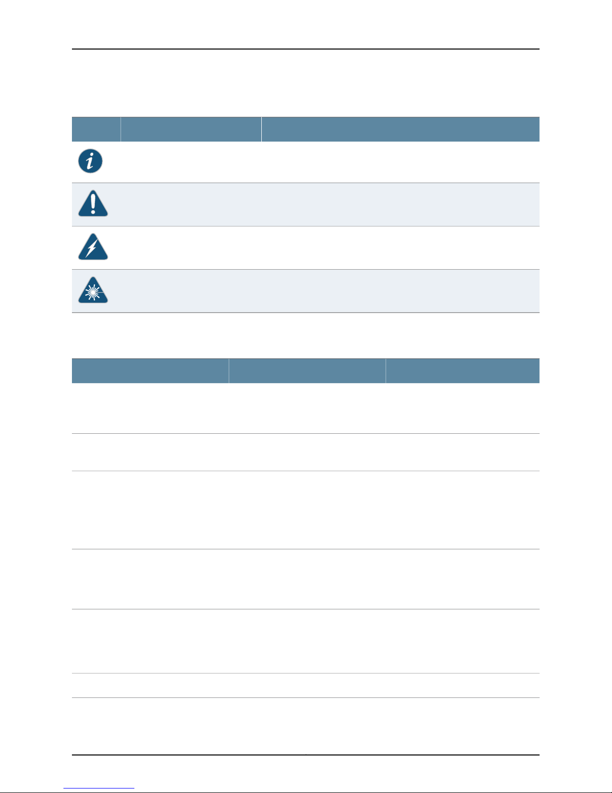
Table 1: Notice Icons
Table 2 on page xx defines the text and syntax conventions used in this guide.
DescriptionMeaningIcon
Indicates important features or instructions.Informational note
Indicates a situation that might result in loss of data or hardware damage.Caution
Alerts you to the risk of personal injury or death.Warning
Alerts you to the risk of personal injury from a laser.Laser warning
Table 2: Text and Syntax Conventions
Represents text that you type.Bold text like this
Fixed-width text like this
Italic text like this
Italic text like this
Text like this
Represents output that appears on the
terminal screen.
•
Introduces or emphasizes important
new terms.
•
Identifies book names.
•
Identifies RFC and Internet draft titles.
Represents variables (options for which
you substitute a value) in commands or
configuration statements.
Represents names of configuration
statements, commands, files, and
directories;configurationhierarchylevels;
or labels on routing platform
components.
ExamplesDescriptionConvention
To enter configuration mode, type
theconfigure command:
user@host> configure
user@host> show chassis alarms
No alarms currently active
•
A policy term is a named structure
that defines match conditions and
actions.
•
Junos OS SystemBasics Configuration
Guide
•
RFC 1997, BGP Communities Attribute
Configure the machine’s domain name:
[edit]
root@# set system domain-name
domain-name
•
To configure a stub area, include the
stub statement at the[edit protocols
ospf area area-id] hierarchy level.
•
The console port is labeled CONSOLE.
stub <default-metric metric>;Enclose optional keywords or variables.< > (angle brackets)
Copyright © 2013, Juniper Networks, Inc.xx

Table 2: Text and Syntax Conventions (continued)
About the Documentation
ExamplesDescriptionConvention
| (pipe symbol)
# (pound sign)
[ ] (square brackets)
Indention and braces ( { } )
; (semicolon)
J-Web GUI Conventions
Bold text like this
Indicates a choice between the mutually
exclusivekeywords or variables on either
side of the symbol. The set of choices is
often enclosed in parenthesesfor clarity.
same lineas the configuration statement
to which it applies.
Enclose a variable for which you can
substitute one or more values.
Identify a level in the configuration
hierarchy.
Identifies a leaf statement at a
configuration hierarchy level.
Represents J-Web graphical user
interface (GUI) items you click or select.
broadcast | multicast
(string1 | string2 | string3)
rsvp { # Required for dynamic MPLS onlyIndicates a comment specified on the
community name members [
community-ids ]
[edit]
routing-options {
static {
route default {
nexthop address;
retain;
}
}
}
•
In the Logical Interfaces box, select
All Interfaces.
•
To cancel the configuration, click
Cancel.
> (bold right angle bracket)
Documentation Feedback
We encourage you to provide feedback, comments, and suggestions so that we can
improve the documentation. You can send your comments to
techpubs-comments@juniper.net, or fill out the documentation feedback form at
https://www.juniper.net/cgi-bin/docbugreport/ . If you are using e-mail, be sure to include
the following information with your comments:
•
Document or topic name
•
URL or page number
•
Software release version (if applicable)
Requesting Technical Support
Technical productsupport isavailablethrough theJuniper Networks Technical Assistance
Center (JTAC). If you are a customer with an active J-Care or JNASC support contract,
Separates levels in a hierarchy of J-Web
selections.
In the configuration editor hierarchy,
select Protocols>Ospf.
xxiCopyright © 2013, Juniper Networks, Inc.

SRX1400 Services Gateway Hardware
or are covered under warranty, and need post-sales technical support, you can access
our tools and resources online or open a case with JTAC.
•
JTAC policies—For a complete understanding of our JTAC procedures and policies,
review the JTAC User Guide located at
http://www.juniper.net/us/en/local/pdf/resource-guides/7100059-en.pdf.
•
Product warranties—For product warranty information, visit
http://www.juniper.net/support/warranty/.
•
JTAC hours of operation—The JTAC centers have resources available 24 hours a day,
7 days a week, 365 days a year.
Self-Help Online Tools and Resources
For quick and easy problem resolution, Juniper Networks has designed an online
self-service portal called the Customer Support Center (CSC) that provides you with the
following features:
•
Find CSC offerings: http://www.juniper.net/customers/support/
•
Search for known bugs: http://www2.juniper.net/kb/
•
Find product documentation: http://www.juniper.net/techpubs/
•
Find solutions and answer questions using our Knowledge Base: http://kb.juniper.net/
•
Download the latest versions of software and review release notes:
http://www.juniper.net/customers/csc/software/
•
Search technical bulletins for relevant hardware and software notifications:
https://www.juniper.net/alerts/
•
Join and participate in the Juniper Networks Community Forum:
http://www.juniper.net/company/communities/
•
Open a case online in the CSC Case Management tool: http://www.juniper.net/cm/
To verifyservice entitlement byproduct serial number, use our SerialNumber Entitlement
(SNE) Tool: https://tools.juniper.net/SerialNumberEntitlementSearch/
Opening a Case with JTAC
You can open a case with JTAC on the Web or by telephone.
•
Use the Case Management tool in the CSC at http://www.juniper.net/cm/.
•
Call 1-888-314-JTAC (1-888-314-5822 toll-free in the USA, Canada, and Mexico).
For international or direct-dial options in countries without toll-free numbers, see
http://www.juniper.net/support/requesting-support.html.
Copyright © 2013, Juniper Networks, Inc.xxii

PART 1
Overview
•
Introduction on page 3
•
Hardware Components and Specifications on page 11
•
Modules Supported By SRX1400, SRX3400, and SRX3600 Services
Gateways on page 31
•
Power Supply Units on page 49
•
Data Flow on page 55
1Copyright © 2013, Juniper Networks, Inc.

SRX1400 Services Gateway Hardware
Copyright © 2013, Juniper Networks, Inc.2

CHAPTER 1
Introduction
•
SRX1400 Services Gateway Description on page 3
•
SRX1400 Services Gateway Models on page 4
•
SRX1400 Services Gateway Hardware Features on page 4
•
SRX1400 Services Gateway Physical Specifications on page 5
•
SRX1400 Services Gateway Environmental Specifications on page 7
•
Understanding the SRX1400 Services Gateway in the Enterprise Network on page 7
•
Understanding the SRX1400 Services Gateway in the Service Provider
Network on page 8
•
Understanding the SRX1400 Services Gateway in the Data Center on page 8
SRX1400 Services Gateway Description
Juniper Networks SRX1400 Services Gateway expands the SRX Series family of
next-generation security platforms, delivering performance and service integration to
environments that require the features without the massive scalability and aggregated
throughput provided by JuniperNetworksSRX3000 lineand SRX5000line. The SRX1400
Services Gateway provides firewall support with key features such as IP Security (IPsec),
virtual private network (VPN), and high-speed deep packet inspection features such as
Intrusion Detection and Prevention (IDP). The SRX1400 device is suited for small to
medium data centers, enterprises, and service provider network security deployments
where consolidation ofsecurity functionality, uncompromised performance, and compact
environmental footprint are requirements.
The SRX1400 ServicesGateway isthree rack units (U) tall. Sixteen devices can bestacked
in a single floor-to-ceiling rack, for increased port density per unit of floor space. The
device provides three common form-factor module (CFM) slots that can be populated
with various CFM cards. The device also has one dedicated slot for System I/O card
(SYSIOC), one dedicated slot for the Routing Engine, two slots for power supplies, and
one slot for the fan tray and air filter.
The SRX1400 Services Gateway runs the Junos operating system (Junos OS). You can
use theJunos OScommand-line interface(CLI) orJ-Web(Web-based graphical interface)
to monitor, configure, troubleshoot, and manage the SRX1400 Services Gateway.
3Copyright © 2013, Juniper Networks, Inc.
SRX1400 Services Gateway Hardware
Related
Documentation
SRX1400 Services Gateway Models on page 4•
• SRX1400 Services Gateway Hardware Features on page 4
• Understanding the SRX1400 Services Gateway in the Enterprise Network on page 7
• Understanding the SRX1400 Services Gateway in the Service Provider Network on
page 8
• Understanding the SRX1400 Services Gateway in the Data Center on page 8
SRX1400 Services Gateway Models
The SRX1400 Services Gateway is available in four models, which are listed in Table 3
on page 4.
Table 3: SRX1400 Services Gateway Models
SRX1400BASE-GE-AC
SRX1400BASE-GE-DC
Device TypeModel Number
SRX1400 Services Gateway with 1-Gigabit Ethernet System
I/O card (SYSIOC), and AC power supply
SRX1400 Services Gateway with 1-Gigabit Ethernet SYSIOC,
and DC power supply
SRX1400BASE-XGE-AC
SRX1400BASE-XGE-DC
SRX1400 Services Gatewaywith 10-Gigabit Ethernet SYSIOC,
and AC power supply
SRX1400 Services Gatewaywith 10-Gigabit Ethernet SYSIOC,
and DC power supply
NOTE: The SRX1400 Services Gateway base models include the Routing
Engine, SYSIOC, and power supply. The Network and Services Processing
Card (NSPC) and IOCs are not provided with the SRX1400 Services Gateway
basemodels. You must order them separately. Contact yourJuniper Networks
customer service representative for more information.
Related
Documentation
SRX1400 Services Gateway Description on page 3•
• SRX1400 Services Gateway Hardware Features on page 4
• SRX1400 Services Gateway Physical Specifications on page 5
• SRX1400 Services Gateway Environmental Specifications on page 7
SRX1400 Services Gateway Hardware Features
Table 4 on page 5 lists the hardware features supported on the SRX1400 Services
Gateway.
Copyright © 2013, Juniper Networks, Inc.4

Table 4: SRX1400 Services Gateway Hardware Features
DescriptionFeature
•
Input Voltage
100 to 240 V AC
•
-40 to -72 V DC
Chapter 1: Introduction
Related
Documentation
Power Supplies
2
SRX1400 Services Gatewayallows twopower supplies
for redundancy. Following power supplies are
supported:
•
AC Power Supply (for AC-powered devices)
•
DC Power Supply (for DC-powered devices)
1Ethernet port (10/100/1000 Mbps)
1Console port
2Universal Serial Bus (USB) ports
1Auxiliary port
2Fans
1Fan tray
1Air filter
SRX1400 Services Gateway Description on page 3•
• SRX1400 Services Gateway Physical Specifications on page 5
• SRX1400 Services Gateway Environmental Specifications on page 7
SRX1400 Services Gateway Physical Specifications
The SRX1400 Services Gateway chassis is a rigid sheet metal structure that houses all
of the other device components. The chassis measures 5.25 in. (13.3 cm) high, 17.5 in.
(44.5 cm) wide, and 13.8 in. (35.05 cm) deep (from the front to the rear of the chassis).
The chassis installsin standard 800-mm (or larger) enclosed cabinets, 19-in. equipment
racks, or telecommunications open-frame racks. Up to 16 services gateways can be
installed in one standard (48-U)rack if the rack can handletheir combined weight,which
can be greater than 677 lb ( 308 kg) (fully-loaded device).
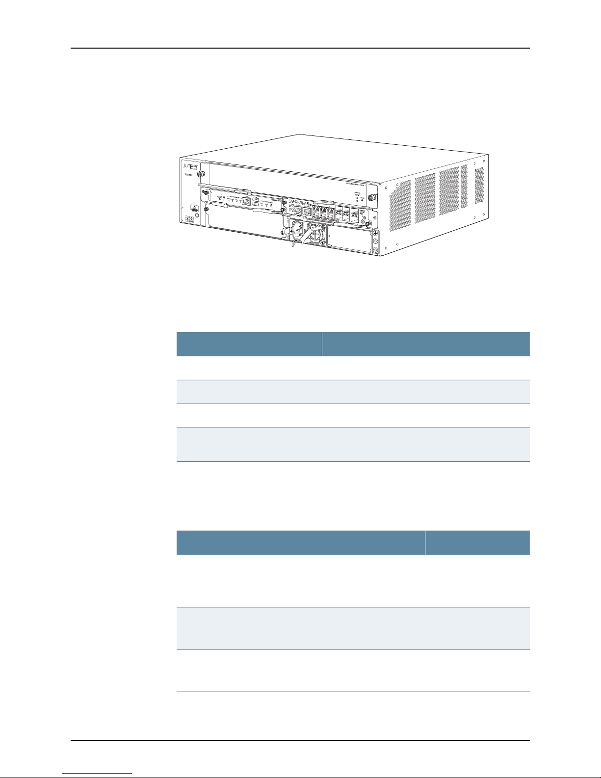
Figure 1 on page 6 shows the SRX1400 Services Gateway chassis.
5Copyright © 2013, Juniper Networks, Inc.
g033500
SRX1400 Services Gateway Hardware
Figure 1: SRX1400 Services Gateway Chassis
Table 5 on page 6 summarizes the physical specifications for the SRX1400 Services
Gateway chassis.
Table 5: SRX1400 Services Gateway Physical Specifications
ValueSpecification
5.25 in. (13.3 cm), 3 rack units (U)Chassis height
17.5 in. (44.5 cm)Chassis width
13.8 in. (35.05 cm)Chassis depth
•
Chassis weight
Base chassis: 29.3 lb (13.3 kg)
•
Fully configured chassis: 42.5 lb (19.3 kg)
Table 6 on page 6 summarizes the weight of the SRX1400 Services Gateway chassis
with different configurations.
Table 6: Weight of the SRX1400 Services Gateway with Different
Configurations
WeightSRX1400 Chassis with Different Configurations
29.3 lb (13.3 kg)Base chassis
(Routing Engine + SYSIOC + 1 power supply + fan tray assembly +
filler cover for CFM slots 1 and 3)
42.5 lb (19.3 kg)Fully configured chassis
(Base chassis + NSPC + IOC + power supply)
(Base chassis - fan tray - power supply)
23.3 lb (10.6 kg)Chassis without fan tray and power supply
Copyright © 2013, Juniper Networks, Inc.6
Chapter 1: Introduction
Related
Documentation
SRX1400 Services Gateway Hardware Features on page 4•
• SRX1400 Services Gateway Environmental Specifications on page 7
• SRX1400 Services Gateway Hardware Components on page 13
• Overview of the SRX1400 Services Gateway CFMs on page 12
SRX1400 Services Gateway Environmental Specifications
Table 7 on page 7 specifies the environmental specifications required for normal
SRX1400 Services Gateway operation.
Table 7: SRX1400 Services Gateway Environmental Specifications
ValueSpecification
No performance degradation to 10,000 ft (3048 m)Altitude
Relative humidity
Temperature
Normal operation ensured inrelative humidity range of 5%to 90%,
noncondensing
Normal operation ensured in temperature range of 32°F (0°C) to
104°F (40°C)
Nonoperating storage temperature in shipping container: –40°F
(–40°C) to 158°F (70°C)
Tested to meet Telcordia Technologies Zone 4 earthquake
requirements
•
AC power: 1653 BTU/hour (W)
•
DC power: 1653 BTU/hour (W)
Related
Documentation
Seismic
Maximum thermal output
SRX1400 Services Gateway Hardware Features on page 4•
• SRX1400 Services Gateway Hardware Components on page 13
• Overview of the SRX1400 Services Gateway CFMs on page 12
Understanding the SRX1400 Services Gateway in the Enterprise Network
The enterprise gateway provides secure access between the Internet and your network
and itsresourcesfor medium toregional sites. Playing the role of your enterprise gateway,
the services gatewayprotects key assets, such as internalclients and application servers,
and webservers, that provide information to partners, remote access users, and general
access to sites.
7Copyright © 2013, Juniper Networks, Inc.

SRX1400 Services Gateway Hardware
The SRX1400 Services Gateway accomplishes these tasks using the following features:
•
A stateful firewall, including denial of service/distributed denial of service (DoS/DDoS)
protection
•
Application support through Application Layer Gateways (ALGs)
•
Quality of service (QoS) traffic management
•
IPsec VPN tunnel termination
•
Application Layer security, including high-speed intrusion protection
Related
Documentation
SRX1400 Services Gateway Models on page 4•
• SRX1400 Services Gateway Hardware Features on page 4
• Understanding the SRX1400 Services Gateway in the Service Provider Network on
page 8
• Understanding the SRX1400 Services Gateway in the Data Center on page 8
Understanding the SRX1400 Services Gateway in the Service Provider Network
The services gateway can be used in the service provider network to provide secure
hosting and network services. When placed at the hosting center, it can perform
provisioning services to multiple customers. When placed in the services network itself,
it protects traffic and performs rate limiting or QoS overlay services.
The SRX1400 Services Gateway accomplishes these tasks using the following features:
•
A stateful firewall, including denial of service/distributed denial of service (DoS/DDoS)
protection
•
Quality of service (QoS) traffic management
•
VPN services
•
Application Layer security, including high-speed intrusion protection.
Related
Documentation
SRX1400 Services Gateway Models on page 4•
• SRX1400 Services Gateway Hardware Features on page 4
• Understanding the SRX1400 Services Gateway in the Enterprise Network on page 7
• Understanding the SRX1400 Services Gateway in the Data Center on page 8
Understanding the SRX1400 Services Gateway in the Data Center
The enterprise data center provides secure access between internal clients and small to
medium server farms, demilitarized zones (DMZs), and hosting sites. In the enterprise
data center, the services gateway is placed in front of your servers, providing secure
partner, extranet, and Web content.
Copyright © 2013, Juniper Networks, Inc.8