

SRX110 Services Gateway Quick Start
Use the instructions in this quick start to help you connect the SRX110 Services Gateway
to your network. For details, see the SRX110 Services Gateway Hardware Guide at
http://www.juniper.net/techpubs/a063.html.
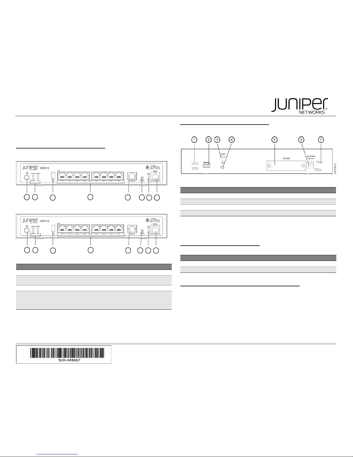
SRX110 Services Gateway Front Panel
SRX110 Services Gateway (SRX110H-VA) Front Panel
SRX110 Services Gateway (SRX110H-VB) Front Panel
SRX110 Services Gateway Back Panel
SRX110 Services Gateway (SRX110H-VA, SRX110H-VB) Back Panel
NOTE: If you experience a problem with the CompactFlash card, you must return the
services gateway for repair or replacement. To do this, contact Juniper Networks
Technical Assistance Center (JTAC).
SRX110 Services Gateway Models
The following models of SRX110 Services Gateways are available:
Connecting and Configuring the SRX Series Device
Use the instructions below to connect and set up the services gateway to protect your
network. Refer to the LEDs on the front of the device to help you determine the status of
the device.
Overview
The services gateway is a security device that requires these basic configuration settings
to function:
Interfaces must be assigned IP addresses.
Interfaces must be bound to zones.
Callout Description Callout Description
1 Power button 5 Console port
2 LEDs: Alarm, Status, Power, and 3G6 Reset Config button
3 Universal Serial Bus (USB) port 7 LEDs: SYNC and TX/RX
4 Fast Ethernet ports 8 For
SRX110H-VA—VDSL/ADSL-POTS
For
SRX110H-VB—VDSL/ADSL-ISDN
g033602
1
3
4
2
5 6
87
g033604
1
3
4
2
5 6
87
Callout Description Callout Description
1 Cable tie holder 5 CompactFlash card
2 3G-WAN (USB port) 6 Power supply point
3 Lock 7 Cable tie holder
4 Grounding point
Device DDR Memory
SRX110H-VA (VDSL/ADSL-POTS) 1 GB
SRX110H-VB (VDSL/ADSL-ISDN) 1 GB
Page 2
Policies must be configured between zones to permit or deny traffic.
Source NAT rules must be set.
The device has the following default configuration set when you power it on for the first
time. You can use the device without performing any initial configuration.
Factory-Default Settings:
Factory-Default Settings for Security Policies:
Factory-Default Settings for NAT Rules:
Task 1: Connect the Power Cable and a Power Source
Connect the power cable to the device and a power source. We recommend using a
surge protector. Note the following indications:
POWER LED (green): The device is receiving power.
STATUS LED (green): The device is operating normally.
ALARM LED (amber): The device is operating normally, although the LED might be
amber because a rescue configuration has not been set yet. This is not a panic
condition.
NOTE: After a rescue configuration has been set, an amber ALARM LED indicates a
minor alarm, and a solid red ALARM LED indicates a major problem on the services
gateway.
NOTE: You must allow the device between 5 and 7 minutes to boot up after you power it
on. Wait until the STATUS LED is solid green before proceeding to the next task.
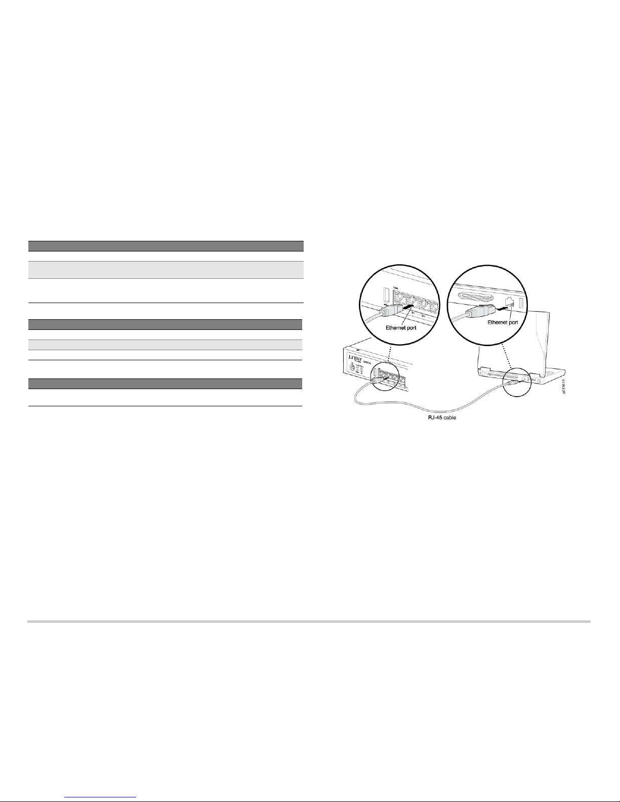
Task 2: Connect the Management Device
Connect the management device to the services gateway using either of the following
methods:
Connect an RJ-45 (Ethernet) cable from any one port between the ports labeled 0/1
and 0/7 (interfaces fe-0/0/1 through fe-0/0/7) on the front panel to the Ethernet port
on the management device (workstation or laptop).
We recommend this connection method. If you are using this method to connect,
proceed with Task 3.
Connect an RJ-45 (Ethernet) cable from the port labeled CONSOLE to the supplied
DB-9 adapter, which then connects to the serial port on the management device.
(Serial port settings: 9600 8-N-1-N)
If you are using this method to connect, proceed with the CLI configuration
instructions available in the Branch SRX Series Services Gateways Golden
Configurations at www.juniper.net/us/en/local/pdf/app-notes/3500153-en.pdf.
See the following illustration for details on connecting a management interface.
Task 3: Ensure That the Management Device Acquires an IP Address
After you connect the management device to the services gateway, the DHCP server
process on the services gateway will assign an IP address automatically to the
management device. Ensure that the management device acquires an IP address on the
192.168.1.0/24 subnetwork (other than 192.168.1.1) from the device.
NOTE: The services gateway functions as a DHCP server and will assign an IP address
to the management device.
NOTE: If an IP address is not assigned to the management device, manually configure
an IP address in the 192.168.1.0/24 subnetwork. Do not assign the 192.168.1.1 IP
address to the management device, as this IP address is assigned to the services
gateway. By default, the DHCP server is enabled on the L3 VLAN interface, (IRB) vlan.0
(fe-0/0/1 to fe-0/0/7), which is configured with an IP address of 192.168.1.1/24.
NOTE: When an SRX110 Services Gateway is powered on for the first time, it boots
using the factory default configuration.
Port Label Interface Security Zones DHCP State IP Address
0/0 fe-0/0/0 untrust client unassigned
0/1 to 0/7 fe-0/0/1 to
fe-0/0/7
trust server 192.168.1.1/24
VDSL/ADSL-POTS
or
VDSL/ADSL-ISDN
pt-1/0/0 untrust client unassigned
Source Zone Destination Zone Policy Action
trust untrust permit
trust trust permit
untrust trust deny
Source Zone Destination Zone Policy Action
trust untrust source NAT to untrust zone
interface
 Loading...