

Juniper SRX100B, SRX100H, SRX100H2 Hardware Manual

SRX100 Services Gateway Hardware Guide for B
and H Model Numbers
Modified: 2015-06-17
Copyright © 2015, Juniper Networks, Inc.

Juniper Networks, Inc.
1133 Innovation Way
Sunnyvale, California 94089
USA
408-745-2000
www.juniper.net
Copyright © 2015, Juniper Networks, Inc. All rights reserved.
Juniper Networks, Junos, Steel-Belted Radius, NetScreen, and ScreenOS are registered trademarks of Juniper Networks, Inc. in the United
States and other countries. The Juniper Networks Logo, the Junos logo, and JunosE are trademarks of Juniper Networks, Inc. All other
trademarks, service marks, registered trademarks, or registered service marks are the property of their respective owners.
Juniper Networks assumes no responsibility for any inaccuracies in this document. Juniper Networks reserves the right to change, modify,
transfer, or otherwise revise this publication without notice.
SRX100 Services Gateway Hardware Guide for B and H Model Numbers
Copyright © 2015, Juniper Networks, Inc.
All rights reserved.
The information in this document is current as of the date on the title page.
YEAR 2000 NOTICE
Juniper Networks hardware and software products are Year 2000 compliant. Junos OS has no known time-related limitations through the
year 2038. However, the NTP application is known to have some difficulty in the year 2036.
END USER LICENSE AGREEMENT
The Juniper Networks product that is the subject of this technical documentation consists of (or is intended for use with) Juniper Networks
software. Use of such software is subject to the terms and conditions of the End User License Agreement (“EULA”) posted at
http://www.juniper.net/support/eula.html. By downloading, installing or using such software, you agree to the terms and conditions of
that EULA.
Copyright © 2015, Juniper Networks, Inc.ii

Table of Contents
About the Documentation . . . . . . . . . . . . . . . . . . . . . . . . . . . . . . . . . . . . . . . . . . . . xiii
Documentation and Release Notes . . . . . . . . . . . . . . . . . . . . . . . . . . . . . . . . . xiii
Supported Platforms . . . . . . . . . . . . . . . . . . . . . . . . . . . . . . . . . . . . . . . . . . . . xiii
Documentation Conventions . . . . . . . . . . . . . . . . . . . . . . . . . . . . . . . . . . . . . . xiii
Documentation Feedback . . . . . . . . . . . . . . . . . . . . . . . . . . . . . . . . . . . . . . . . . xv
Requesting Technical Support . . . . . . . . . . . . . . . . . . . . . . . . . . . . . . . . . . . . . xvi
Self-Help Online Tools and Resources . . . . . . . . . . . . . . . . . . . . . . . . . . . xvi
Opening a Case with JTAC . . . . . . . . . . . . . . . . . . . . . . . . . . . . . . . . . . . . . xvi
Part 1 Overview
Chapter 1 System Overview . . . . . . . . . . . . . . . . . . . . . . . . . . . . . . . . . . . . . . . . . . . . . . . . . . . 3
SRX100 Services Gateway Description . . . . . . . . . . . . . . . . . . . . . . . . . . . . . . . . . . . 3
About the SRX100 Services Gateway . . . . . . . . . . . . . . . . . . . . . . . . . . . . . . . . 3
SRX100 Services Gateway Models . . . . . . . . . . . . . . . . . . . . . . . . . . . . . . . . . . . 3
Accessing the SRX100 Services Gateway . . . . . . . . . . . . . . . . . . . . . . . . . . . . . 4
SRX100 Services Gateway Features and Functions . . . . . . . . . . . . . . . . . . . . . . . . . 4
Chapter 2 Hardware Component Overview . . . . . . . . . . . . . . . . . . . . . . . . . . . . . . . . . . . . . 7
SRX100 Services Gateway LEDs . . . . . . . . . . . . . . . . . . . . . . . . . . . . . . . . . . . . . . . . 7
SRX100 Services Gateway Front Panel LEDs . . . . . . . . . . . . . . . . . . . . . . . . . . . 7
SRX100 Services Gateway Ethernet Port LEDs . . . . . . . . . . . . . . . . . . . . . . . . . 9
SRX100 Services Gateway Power Supply . . . . . . . . . . . . . . . . . . . . . . . . . . . . . . . . 10
SRX100 Services Gateway Boot Devices and Dual-Root Partitioning Scheme . . . 11
Boot Devices . . . . . . . . . . . . . . . . . . . . . . . . . . . . . . . . . . . . . . . . . . . . . . . . . . . . 11
Dual-Root Partitioning Scheme . . . . . . . . . . . . . . . . . . . . . . . . . . . . . . . . . . . . . 11
Chapter 3 Chassis Description . . . . . . . . . . . . . . . . . . . . . . . . . . . . . . . . . . . . . . . . . . . . . . . . 13
SRX100 Services Gateway Front Panel and Back Panel Views . . . . . . . . . . . . . . . 13
SRX100 Services Gateway Front Panel . . . . . . . . . . . . . . . . . . . . . . . . . . . . . . 13
SRX100 Services Gateway Back Panel . . . . . . . . . . . . . . . . . . . . . . . . . . . . . . . 14
SRX100 Services Gateway Built-In Interfaces . . . . . . . . . . . . . . . . . . . . . . . . . . . . . 15
Part 2 Site Planning and Specifications
Chapter 4 Planning and Preparing the Site . . . . . . . . . . . . . . . . . . . . . . . . . . . . . . . . . . . . . 21
Site Preparation Checklist for the SRX100 Services Gateway . . . . . . . . . . . . . . . . 21
General Site Guidelines for Installing the SRX100 Services Gateway . . . . . . . . . . 24
SRX100 Services Gateway Specifications . . . . . . . . . . . . . . . . . . . . . . . . . . . . . . . 24
SRX100 Services Gateway Cabinet Requirements . . . . . . . . . . . . . . . . . . . . . . . . . 25
SRX100 Services Gateway Rack Requirements . . . . . . . . . . . . . . . . . . . . . . . . . . . 26
iiiCopyright © 2015, Juniper Networks, Inc.

SRX100 Services Gateway Hardware Guide for B and H Model Numbers
Clearance Requirements for Airflow and Hardware Maintenance of the SRX100
Services Gateway . . . . . . . . . . . . . . . . . . . . . . . . . . . . . . . . . . . . . . . . . . . . . . . 27
Chapter 5 Power Requirements and Specifications . . . . . . . . . . . . . . . . . . . . . . . . . . . . . 29
SRX100 Services Gateway Site Electrical Wiring Guidelines . . . . . . . . . . . . . . . . . 29
SRX100 Services Gateway Electrical and Power Requirements . . . . . . . . . . . . . . 30
SRX100 Services Gateway Power Specifications and Requirements . . . . . . . . . . . 31
Chapter 6 Cable Specifications and Pinouts . . . . . . . . . . . . . . . . . . . . . . . . . . . . . . . . . . . 33
Interface Cable and Wire Specifications for the SRX100 Services Gateway . . . . . 33
RJ-45 Connector Pinouts for the SRX100 Services Gateway Ethernet Port . . . . . 33
RJ-45 Connector Pinouts for the SRX100 Services Gateway Console Port . . . . . . 34
Part 3 Initial Installation and Configuration
Chapter 7 Installation Overview . . . . . . . . . . . . . . . . . . . . . . . . . . . . . . . . . . . . . . . . . . . . . . 39
Installation Overview for the SRX100 Services Gateway . . . . . . . . . . . . . . . . . . . . 40
Required Tools and Parts for Installing and Maintaining the SRX100 Services
Gateway . . . . . . . . . . . . . . . . . . . . . . . . . . . . . . . . . . . . . . . . . . . . . . . . . . . . . . . 41
SRX100 Services Gateway Autoinstallation Overview . . . . . . . . . . . . . . . . . . . . . . 42
Chapter 8 Unpacking the Services Gateway . . . . . . . . . . . . . . . . . . . . . . . . . . . . . . . . . . . 43
Unpacking the SRX100 Services Gateway . . . . . . . . . . . . . . . . . . . . . . . . . . . . . . . 43
Verifying Parts Received with the SRX100 Services Gateway . . . . . . . . . . . . . . . . 44
Chapter 9 Installing the Mounting Hardware . . . . . . . . . . . . . . . . . . . . . . . . . . . . . . . . . . . 47
Preparing the SRX100 Services Gateway for Rack-Mount Installation . . . . . . . . . 47
Preparing the SRX100 Services Gateway for Desk-Mount Installation . . . . . . . . . 48
Preparing the SRX100 Services Gateway for Wall-Mount Installation . . . . . . . . . 48
Chapter 10 Installing the Services Gateway . . . . . . . . . . . . . . . . . . . . . . . . . . . . . . . . . . . . . 51
Installing the SRX100 Services Gateway in a Rack . . . . . . . . . . . . . . . . . . . . . . . . . 51
Installing the SRX100 Services Gateway on a Desk . . . . . . . . . . . . . . . . . . . . . . . . 52
Installing the SRX100 Services Gateway on a Wall . . . . . . . . . . . . . . . . . . . . . . . . 54
Chapter 11 Grounding the SRX100 Services Gateway . . . . . . . . . . . . . . . . . . . . . . . . . . . . 57
Grounding the SRX100 Services Gateway . . . . . . . . . . . . . . . . . . . . . . . . . . . . . . . . 57
Chapter 12 Connecting the SRX100 Services Gateway to External Devices . . . . . . . . . . 61
Connecting and Organizing Interface Cables to the SRX100 Services
Gateway . . . . . . . . . . . . . . . . . . . . . . . . . . . . . . . . . . . . . . . . . . . . . . . . . . . . . . . 61
Connecting the Modem at the SRX100 Services Gateway End . . . . . . . . . . . . . . . 62
Connecting the Modem to the Console Port on the SRX100 Services
Gateway . . . . . . . . . . . . . . . . . . . . . . . . . . . . . . . . . . . . . . . . . . . . . . . . . . . . . . 63
Connecting to the CLI at the User End for the SRX100 Services Gateway . . . . . . 63
Chapter 13 Providing Power to the SRX100 Services Gateway . . . . . . . . . . . . . . . . . . . . 65
Connecting the SRX100 Services Gateway to the Power Supply . . . . . . . . . . . . . 65
Powering On and Powering Off the SRX100 Services Gateway . . . . . . . . . . . . . . 66
Powering On the SRX100 Services Gateway . . . . . . . . . . . . . . . . . . . . . . . . . . 66
Powering Off the SRX100 Services Gateway . . . . . . . . . . . . . . . . . . . . . . . . . . 67
Copyright © 2015, Juniper Networks, Inc.iv

Table of Contents
Chapter 14 Performing Initial Configuration . . . . . . . . . . . . . . . . . . . . . . . . . . . . . . . . . . . . 69
SRX100 Services Gateway Software Configuration Overview . . . . . . . . . . . . . . . . 69
Preparing the SRX100 Services Gateway for Configuration . . . . . . . . . . . . . . 69
Understanding the Factory Default Configuration . . . . . . . . . . . . . . . . . . . . . . 70
Understanding Built-In Ethernet Ports and Initial Configuration . . . . . . . . . . 70
Mapping the Chassis Cluster Ports . . . . . . . . . . . . . . . . . . . . . . . . . . . . . . . . . . 71
Understanding Management Access . . . . . . . . . . . . . . . . . . . . . . . . . . . . . . . . 72
Connecting to the SRX100 Services Gateway Setup Wizard . . . . . . . . . . . . . . . . . 73
SRX100 Services Gateway Secure Web Access Overview . . . . . . . . . . . . . . . . . . . 74
Connecting an SRX100 Services Gateway to the CLI Locally . . . . . . . . . . . . . . . . . 75
Connecting an SRX100 Services Gateway to the CLI Remotely . . . . . . . . . . . . . . . 76
Viewing Factory-Default Settings of the SRX100 Services Gateway . . . . . . . . . . . 77
Performing Initial Software Configuration on the SRX100 Services Gateway
Using the CLI . . . . . . . . . . . . . . . . . . . . . . . . . . . . . . . . . . . . . . . . . . . . . . . . . . . 83
Performing Initial Software Configuration on the SRX100 Services Gateway
Using the J-Web Interface . . . . . . . . . . . . . . . . . . . . . . . . . . . . . . . . . . . . . . . . 86
Establishing Basic Connectivity . . . . . . . . . . . . . . . . . . . . . . . . . . . . . . . . . . . . 86
Configuring Basic System Properties . . . . . . . . . . . . . . . . . . . . . . . . . . . . . . . . 87
Upgrading theSRX100 Services GatewayLowMemory Version to a HighMemory
Version . . . . . . . . . . . . . . . . . . . . . . . . . . . . . . . . . . . . . . . . . . . . . . . . . . . . . . . 90
Part 4 Maintaining and Troubleshooting Components
Chapter 15 Maintaining Components . . . . . . . . . . . . . . . . . . . . . . . . . . . . . . . . . . . . . . . . . . 93
Maintaining the SRX100 Services Gateway Hardware Components . . . . . . . . . . 93
Chapter 16 Troubleshooting Components . . . . . . . . . . . . . . . . . . . . . . . . . . . . . . . . . . . . . . 95
Monitoring the SRX100 Services Gateway Chassis Using the CLI . . . . . . . . . . . . . 95
Monitoring the SRX100 Services Gateway Components Using LEDs . . . . . . . . . . 97
Monitoring the SRX100 Services Gateway Using Chassis Alarm Conditions . . . . 99
Monitoring the SRX100 Services Gateway Power System . . . . . . . . . . . . . . . . . . 101
Using the Reset Config Button on the SRX100 Services Gateway . . . . . . . . . . . . 102
Changing the Reset Config Button Behavior on the SRX100 Services
Gateway . . . . . . . . . . . . . . . . . . . . . . . . . . . . . . . . . . . . . . . . . . . . . . . . . . . . . . 103
Juniper Networks Technical Assistance Center . . . . . . . . . . . . . . . . . . . . . . . . . . . 103
Part 5 Replacing Components
Chapter 17 Contacting Customer Support and Returning Components . . . . . . . . . . . . 107
Contacting Customer Support . . . . . . . . . . . . . . . . . . . . . . . . . . . . . . . . . . . . . . . . 107
Return Procedure for the SRX100 Services Gateway . . . . . . . . . . . . . . . . . . . . . . 108
InformationYou MightNeed to Supply to JuniperNetworksTechnical Assistance
Center . . . . . . . . . . . . . . . . . . . . . . . . . . . . . . . . . . . . . . . . . . . . . . . . . . . . . . . 108
Locating the SRX100 Services Gateway Component Serial Number and Agency
Labels . . . . . . . . . . . . . . . . . . . . . . . . . . . . . . . . . . . . . . . . . . . . . . . . . . . . . . . 109
Packing the SRX100 Services Gateway and Components for Shipment . . . . . . . 110
vCopyright © 2015, Juniper Networks, Inc.

SRX100 Services Gateway Hardware Guide for B and H Model Numbers
Part 6 Safety and Regulatory Compliance Information
Chapter 18 General Safety Guidelines and Warnings . . . . . . . . . . . . . . . . . . . . . . . . . . . . . 115
SRX100 Services Gateway Definition of Safety Warning Levels . . . . . . . . . . . . . . 115
SRX100 Services Gateway General Safety Guidelines and Warnings . . . . . . . . . . 117
General Safety Guidelines and Warnings . . . . . . . . . . . . . . . . . . . . . . . . . . . . . 117
Qualified Personnel Warning . . . . . . . . . . . . . . . . . . . . . . . . . . . . . . . . . . . . . . 118
Restricted Access Area Warning . . . . . . . . . . . . . . . . . . . . . . . . . . . . . . . . . . . 118
Preventing Electrostatic Discharge Damage to the Services Gateway . . . . . 120
SRX100 Services Gateway Safety Requirements, Warnings, and Guidelines . . . . 121
Chapter 19 Fire Safety Requirements . . . . . . . . . . . . . . . . . . . . . . . . . . . . . . . . . . . . . . . . . . 123
SRX100 Services Gateway Fire Safety Requirements . . . . . . . . . . . . . . . . . . . . . . 123
Chapter 20 Installation Safety Guidelines and Warnings . . . . . . . . . . . . . . . . . . . . . . . . . 125
SRX100 Services Gateway Installation Safety Guidelines and Warnings . . . . . . . 125
Chapter 21 Laser and LED Safety Guidelines and Warnings . . . . . . . . . . . . . . . . . . . . . . . 131
SRX100 Services Gateway Laser and LED Safety Guidelines and Warnings . . . . 131
Laser and LED Safety Guidelines and Warnings . . . . . . . . . . . . . . . . . . . . . . . 131
General Laser Safety Guidelines . . . . . . . . . . . . . . . . . . . . . . . . . . . . . . . . 131
Class 1 Laser Product Warning . . . . . . . . . . . . . . . . . . . . . . . . . . . . . . . . . 131
Class 1 LED Product Warning . . . . . . . . . . . . . . . . . . . . . . . . . . . . . . . . . . 132
Laser Beam Warning . . . . . . . . . . . . . . . . . . . . . . . . . . . . . . . . . . . . . . . . 132
Radiation from Open Port Apertures Warning . . . . . . . . . . . . . . . . . . . . 133
Chapter 22 Maintenance and Operational Safety Guidelines and Warnings . . . . . . . . 135
SRX100 Services Gateway Maintenance and Operational Safety Guidelines and
Warnings . . . . . . . . . . . . . . . . . . . . . . . . . . . . . . . . . . . . . . . . . . . . . . . . . . . . . 135
Safety Guidelines and Warnings . . . . . . . . . . . . . . . . . . . . . . . . . . . . . . . . . . . 135
Battery Handling Warning . . . . . . . . . . . . . . . . . . . . . . . . . . . . . . . . . . . . 135
Jewelry Removal Warning . . . . . . . . . . . . . . . . . . . . . . . . . . . . . . . . . . . . 136
Lightning Activity Warning . . . . . . . . . . . . . . . . . . . . . . . . . . . . . . . . . . . . 137
Operating Temperature Warning . . . . . . . . . . . . . . . . . . . . . . . . . . . . . . . 138
Product Disposal Warning . . . . . . . . . . . . . . . . . . . . . . . . . . . . . . . . . . . . 139
Chapter 23 Electrical Safety Guidelines and Warnings . . . . . . . . . . . . . . . . . . . . . . . . . . . 141
SRX100 Services Gateway Electrical Safety Guidelines and Warnings . . . . . . . . . 141
Electrical Safety Guidelines and Warnings . . . . . . . . . . . . . . . . . . . . . . . . . . . 141
In Case of Electrical Accident . . . . . . . . . . . . . . . . . . . . . . . . . . . . . . . . . . 141
General Electrical Safety Guidelines and Warnings . . . . . . . . . . . . . . . . . 141
Chapter 24 Agency Approvals and Regulatory Compliance Information . . . . . . . . . . . 143
SRX100 Services Gateway Agency Approvals . . . . . . . . . . . . . . . . . . . . . . . . . . . . 143
SRX100 Services Gateway Compliance Statements for EMC Requirements . . . 144
Canada . . . . . . . . . . . . . . . . . . . . . . . . . . . . . . . . . . . . . . . . . . . . . . . . . . . . . . 144
European Community . . . . . . . . . . . . . . . . . . . . . . . . . . . . . . . . . . . . . . . . . . . 144
Japan . . . . . . . . . . . . . . . . . . . . . . . . . . . . . . . . . . . . . . . . . . . . . . . . . . . . . . . . 145
Korean . . . . . . . . . . . . . . . . . . . . . . . . . . . . . . . . . . . . . . . . . . . . . . . . . . . . . . . 145
United States . . . . . . . . . . . . . . . . . . . . . . . . . . . . . . . . . . . . . . . . . . . . . . . . . . 145
SRX100 Services Gateway Compliance Statements for Environmental
Requirements . . . . . . . . . . . . . . . . . . . . . . . . . . . . . . . . . . . . . . . . . . . . . . . . . 146
Copyright © 2015, Juniper Networks, Inc.vi

Part 7 Index
Index . . . . . . . . . . . . . . . . . . . . . . . . . . . . . . . . . . . . . . . . . . . . . . . . . . . . . . . . 149
Table of Contents
viiCopyright © 2015, Juniper Networks, Inc.

SRX100 Services Gateway Hardware Guide for B and H Model Numbers
Copyright © 2015, Juniper Networks, Inc.viii

List of Figures
Part 1 Overview
Chapter 2 Hardware Component Overview . . . . . . . . . . . . . . . . . . . . . . . . . . . . . . . . . . . . . 7
Figure 1: SRX100 Services Gateway Front Panel LEDs . . . . . . . . . . . . . . . . . . . . . . . 7
Figure 2: SRX100 Services Gateway Ethernet Port LEDs . . . . . . . . . . . . . . . . . . . . 10
Chapter 3 Chassis Description . . . . . . . . . . . . . . . . . . . . . . . . . . . . . . . . . . . . . . . . . . . . . . . . 13
Figure 3: SRX100 Services Gateway Front Panel . . . . . . . . . . . . . . . . . . . . . . . . . . . 13
Figure 4: SRX100 Services Gateway Back Panel . . . . . . . . . . . . . . . . . . . . . . . . . . . 14
Part 2 Site Planning and Specifications
Chapter 4 Planning and Preparing the Site . . . . . . . . . . . . . . . . . . . . . . . . . . . . . . . . . . . . . 21
Figure 5: SRX100 Services Gateway . . . . . . . . . . . . . . . . . . . . . . . . . . . . . . . . . . . . 25
Chapter 6 Cable Specifications and Pinouts . . . . . . . . . . . . . . . . . . . . . . . . . . . . . . . . . . . 33
Figure 6: Ethernet Cable Connector (RJ-45) . . . . . . . . . . . . . . . . . . . . . . . . . . . . . . 33
Figure 7: Console Cable Connector . . . . . . . . . . . . . . . . . . . . . . . . . . . . . . . . . . . . . 34
Part 3 Initial Installation and Configuration
Chapter 10 Installing the Services Gateway . . . . . . . . . . . . . . . . . . . . . . . . . . . . . . . . . . . . . 51
Figure 8: Installing the SRX100 Services Gateway in a Rack . . . . . . . . . . . . . . . . . . 51
Figure 9: Hanging the SRX100 Services Gateway in a Rack . . . . . . . . . . . . . . . . . . 52
Figure 10: Installing the SRX100 Services Gateway on a Desk . . . . . . . . . . . . . . . . 53
Figure 11: Installing the SRX100 Services Gateway on a Wall . . . . . . . . . . . . . . . . . 54
Figure 12: Hanging the SRX100 Services Gateway on a Wall . . . . . . . . . . . . . . . . . 55
Chapter 11 Grounding the SRX100 Services Gateway . . . . . . . . . . . . . . . . . . . . . . . . . . . . 57
Figure 13: Grounding the SRX100 Services Gateway . . . . . . . . . . . . . . . . . . . . . . . . 57
Chapter 13 Providing Power to the SRX100 Services Gateway . . . . . . . . . . . . . . . . . . . . 65
Figure 14: Connecting the Services Gateway to the Power Supply . . . . . . . . . . . . 65
Chapter 14 Performing Initial Configuration . . . . . . . . . . . . . . . . . . . . . . . . . . . . . . . . . . . . 69
Figure 15: Connecting to the Ethernet Port on an SRX100 Services Gateway . . . . 73
Figure 16: Connecting to the Console Port on an SRX100 Services Gateway . . . . 75
Part 5 Replacing Components
Chapter 17 Contacting Customer Support and Returning Components . . . . . . . . . . . . 107
Figure 17: Location of SRX100 Services Gateway Serial Number and Agency
Labels . . . . . . . . . . . . . . . . . . . . . . . . . . . . . . . . . . . . . . . . . . . . . . . . . . . . . . . . 110
ixCopyright © 2015, Juniper Networks, Inc.

SRX100 Services Gateway Hardware Guide for B and H Model Numbers
Part 6 Safety and Regulatory Compliance Information
Chapter 18 General Safety Guidelines and Warnings . . . . . . . . . . . . . . . . . . . . . . . . . . . . . 115
Figure 18: Placing a Component into an Electrostatic Bag . . . . . . . . . . . . . . . . . . 120
Copyright © 2015, Juniper Networks, Inc.x

List of Tables
About the Documentation . . . . . . . . . . . . . . . . . . . . . . . . . . . . . . . . . . . . . . . . . xiii
Table 1: Notice Icons . . . . . . . . . . . . . . . . . . . . . . . . . . . . . . . . . . . . . . . . . . . . . . . . . xiv
Table 2: Text and Syntax Conventions . . . . . . . . . . . . . . . . . . . . . . . . . . . . . . . . . . xiv
Part 1 Overview
Chapter 1 System Overview . . . . . . . . . . . . . . . . . . . . . . . . . . . . . . . . . . . . . . . . . . . . . . . . . . . 3
Table 3: SRX100 Services Gateway Models . . . . . . . . . . . . . . . . . . . . . . . . . . . . . . . 3
Table 4: SRX100 Services Gateway Hardware Features . . . . . . . . . . . . . . . . . . . . . . 5
Chapter 2 Hardware Component Overview . . . . . . . . . . . . . . . . . . . . . . . . . . . . . . . . . . . . . 7
Table 5: SRX100 Services Gateway Front Panel LEDs . . . . . . . . . . . . . . . . . . . . . . . 8
Table 6: SRX100 Services Gateway Built-In Ethernet Port LEDs . . . . . . . . . . . . . . 10
Chapter 3 Chassis Description . . . . . . . . . . . . . . . . . . . . . . . . . . . . . . . . . . . . . . . . . . . . . . . . 13
Table 7: SRX100 Services Gateway Front Panel Components . . . . . . . . . . . . . . . . 13
Table 8: SRX100 Services Gateway Back Panel . . . . . . . . . . . . . . . . . . . . . . . . . . . 14
Table 9: SRX100 Services Gateway Built-In Hardware Interfaces . . . . . . . . . . . . . 15
Part 2 Site Planning and Specifications
Chapter 4 Planning and Preparing the Site . . . . . . . . . . . . . . . . . . . . . . . . . . . . . . . . . . . . . 21
Table 10: Site Preparation Checklist for Services Gateway Installation . . . . . . . . . 21
Table 11: SRX100 Services Gateway Specifications . . . . . . . . . . . . . . . . . . . . . . . . 24
Table 12: SRX100 Services Gateway Cabinet Requirements . . . . . . . . . . . . . . . . . 26
Table 13: Rack Requirements for the Services Gateway . . . . . . . . . . . . . . . . . . . . . 27
Table 14: Clearance Requirements for the SRX100 Services Gateway . . . . . . . . . 28
Chapter 5 Power Requirements and Specifications . . . . . . . . . . . . . . . . . . . . . . . . . . . . . 29
Table 15: Site Electrical Wiring Guidelines for the Services Gateway . . . . . . . . . . . 29
Table 16: Power System Electrical Specifications for the SRX100 Services
Chapter 6 Cable Specifications and Pinouts . . . . . . . . . . . . . . . . . . . . . . . . . . . . . . . . . . . 33
Table 17: Cable and Wire Specifications for Ports . . . . . . . . . . . . . . . . . . . . . . . . . . 33
Table 18: RJ-45 Connector Pinouts for the Services Gateway Ethernet Port . . . . . 34
Table 19: RJ-45 Connector Pinouts for the Services Gateway Console Port . . . . . 34
Gateway . . . . . . . . . . . . . . . . . . . . . . . . . . . . . . . . . . . . . . . . . . . . . . . . . . . . . . . 31
Part 3 Initial Installation and Configuration
Chapter 7 Installation Overview . . . . . . . . . . . . . . . . . . . . . . . . . . . . . . . . . . . . . . . . . . . . . . 39
Table 20: Installation Process Order for the SRX100 Services Gateway . . . . . . . . 40
xiCopyright © 2015, Juniper Networks, Inc.

SRX100 Services Gateway Hardware Guide for B and H Model Numbers
Table 21: Required Tools and Parts for Installing and Maintaining the SRX100
Services Gateway . . . . . . . . . . . . . . . . . . . . . . . . . . . . . . . . . . . . . . . . . . . . . . . 41
Chapter 8 Unpacking the Services Gateway . . . . . . . . . . . . . . . . . . . . . . . . . . . . . . . . . . . 43
Table 22: Parts List for a Fully Configured SRX100 Services Gateway . . . . . . . . . . 44
Table 23: Accessory Parts List for the SRX100 Services Gateway . . . . . . . . . . . . . 44
Chapter 11 Grounding the SRX100 Services Gateway . . . . . . . . . . . . . . . . . . . . . . . . . . . . 57
Table 24: SRX100 Services Gateway Grounding Components . . . . . . . . . . . . . . . 58
Table 25: Grounding Cable Specifications for the Services Gateway . . . . . . . . . . 58
Chapter 12 Connecting the SRX100 Services Gateway to External Devices . . . . . . . . . . 61
Table 26: Port Settings for Configuring the Modem on the Services Gateway
End . . . . . . . . . . . . . . . . . . . . . . . . . . . . . . . . . . . . . . . . . . . . . . . . . . . . . . . . . . 62
Table 27: Port Settings for Connecting to the CLI at User End . . . . . . . . . . . . . . . . 64
Chapter 14 Performing Initial Configuration . . . . . . . . . . . . . . . . . . . . . . . . . . . . . . . . . . . . 69
Table 28: Mapping the Chassis Cluster Ports on an SRX100 Services
Gateway . . . . . . . . . . . . . . . . . . . . . . . . . . . . . . . . . . . . . . . . . . . . . . . . . . . . . . . 71
Table 29: Console Port Settings for the SRX100 Services Gateway . . . . . . . . . . . 76
Table 30: Required Setup Fields . . . . . . . . . . . . . . . . . . . . . . . . . . . . . . . . . . . . . . . 88
Table 31: Optional Setup Fields . . . . . . . . . . . . . . . . . . . . . . . . . . . . . . . . . . . . . . . . 88
Part 4 Maintaining and Troubleshooting Components
Chapter 15 Maintaining Components . . . . . . . . . . . . . . . . . . . . . . . . . . . . . . . . . . . . . . . . . . 93
Table 32: Maintenance Procedures for the SRX100 Services Gateway Hardware
Components . . . . . . . . . . . . . . . . . . . . . . . . . . . . . . . . . . . . . . . . . . . . . . . . . . . 93
Chapter 16 Troubleshooting Components . . . . . . . . . . . . . . . . . . . . . . . . . . . . . . . . . . . . . . 95
Table 33: Services Gateway LED Status on Startup . . . . . . . . . . . . . . . . . . . . . . . . 97
Table 34: Component LEDs on the Services Gateway . . . . . . . . . . . . . . . . . . . . . . 98
Table 35: SRX100 Services Gateway Chassis Alarm Conditions and Corrective
Actions . . . . . . . . . . . . . . . . . . . . . . . . . . . . . . . . . . . . . . . . . . . . . . . . . . . . . . . 100
Table 36: Services Gateway Power LED Status . . . . . . . . . . . . . . . . . . . . . . . . . . . 101
Copyright © 2015, Juniper Networks, Inc.xii

About the Documentation
•
Documentation and Release Notes on page xiii
•
Supported Platforms on page xiii
•
Documentation Conventions on page xiii
•
Documentation Feedback on page xv
•
Requesting Technical Support on page xvi
Documentation and Release Notes
To obtain the most current version of all Juniper Networks®technical documentation,
see the product documentation page on the Juniper Networks website at
http://www.juniper.net/techpubs/.
If the information in the latest release notes differs from the information in the
documentation, follow the product Release Notes.
Juniper Networks Books publishes books by Juniper Networks engineers and subject
matter experts. These books go beyond the technical documentation to explore the
nuances of network architecture, deployment, and administration. The current list can
be viewed at http://www.juniper.net/books.
Supported Platforms
For the features described in this document, the following platforms are supported:
•
SRX100
Documentation Conventions
Table 1 on page xiv defines notice icons used in this guide.
xiiiCopyright © 2015, Juniper Networks, Inc.

SRX100 Services Gateway Hardware Guide for B and H Model Numbers
Table 1: Notice Icons
DescriptionMeaningIcon
Indicates important features or instructions.Informational note
Indicates a situation that might result in loss of data or hardware damage.Caution
Alerts you to the risk of personal injury or death.Warning
Alerts you to the risk of personal injury from a laser.Laser warning
Indicates helpful information.Tip
Table 2 on page xiv defines the text and syntax conventions used in this guide.
Table 2: Text and Syntax Conventions
Represents text that you type.Bold text like this
Fixed-width text like this
Italic text like this
Italic text like this
Represents output that appears on the
terminal screen.
•
Introduces or emphasizes important
new terms.
•
Identifies guide names.
•
Identifies RFC and Internet draft titles.
Represents variables (options for which
you substitute a value) in commands or
configuration statements.
Alerts you to a recommended use or implementation.Best practice
ExamplesDescriptionConvention
To enter configuration mode, type the
configure command:
user@host> configure
user@host> show chassis alarms
No alarms currently active
•
A policy term is a named structure
that defines match conditions and
actions.
•
Junos OS CLI User Guide
•
RFC 1997, BGP Communities Attribute
Configure the machine’s domain name:
[edit]
root@# set system domain-name
domain-name
Copyright © 2015, Juniper Networks, Inc.xiv

Table 2: Text and Syntax Conventions (continued)
Text like this
Represents names of configuration
statements, commands, files, and
directories;configuration hierarchy levels;
or labels on routing platform
components.
About the Documentation
ExamplesDescriptionConvention
•
To configure a stub area, include the
stub statement at the [edit protocols
ospf area area-id] hierarchy level.
•
The console port islabeledCONSOLE.
stub <default-metric metric>;Encloses optional keywords or variables.< > (angle brackets)
| (pipe symbol)
# (pound sign)
[ ] (square brackets)
Indention and braces ( { } )
; (semicolon)
GUI Conventions
Bold text like this
Indicates a choice between the mutually
exclusivekeywordsor variables on either
side of the symbol. The set of choices is
often enclosed in parenthesesfor clarity.
same lineasthe configuration statement
to which it applies.
Encloses a variable for which you can
substitute one or more values.
Identifies a level in the configuration
hierarchy.
Identifies a leaf statement at a
configuration hierarchy level.
Representsgraphicaluser interface(GUI)
items you click or select.
broadcast | multicast
(string1 | string2 | string3)
rsvp { # Required for dynamic MPLS onlyIndicates a comment specified on the
community name members [
community-ids ]
[edit]
routing-options {
static {
route default {
nexthop address;
retain;
}
}
}
•
In the Logical Interfaces box, select
All Interfaces.
•
To cancel the configuration, click
Cancel.
> (bold right angle bracket)
Documentation Feedback
We encourage you to provide feedback, comments, and suggestions so that we can
improve the documentation. You can provide feedback by using either of the following
methods:
•
Online feedback rating system—On any page at the Juniper Networks Technical
Documentation site at http://www.juniper.net/techpubs/index.html, simply click the
stars to rate the content,and usethe pop-upform to provide uswith information about
your experience. Alternately, you can use the online feedback form at
https://www.juniper.net/cgi-bin/docbugreport/.
Separates levels in a hierarchy of menu
selections.
In the configuration editor hierarchy,
select Protocols>Ospf.
xvCopyright © 2015, Juniper Networks, Inc.

SRX100 Services Gateway Hardware Guide for B and H Model Numbers
•
E-mail—Sendyourcomments to techpubs-comments@juniper.net. Includethe document
or topic name, URL or page number, and software version (if applicable).
Requesting Technical Support
Technical product support is availablethrough the Juniper Networks Technical Assistance
Center (JTAC). If you are a customer with an active J-Care or Partner Support Service
support contract, or are covered under warranty, and need post-sales technical support,
you can access our tools and resources online or open a case with JTAC.
•
JTAC policies—For a complete understanding of our JTAC procedures and policies,
review the JTAC User Guide located at
http://www.juniper.net/us/en/local/pdf/resource-guides/7100059-en.pdf.
•
Product warranties—For product warranty information, visit
http://www.juniper.net/support/warranty/.
•
JTAC hours of operation—The JTAC centers have resources available 24 hours a day,
7 days a week, 365 days a year.
Self-Help Online Tools and Resources
For quick and easy problem resolution, Juniper Networks has designed an online
self-service portal called the Customer Support Center (CSC) that provides you with the
following features:
•
Find CSC offerings: http://www.juniper.net/customers/support/
•
Search for known bugs: http://www2.juniper.net/kb/
•
Find product documentation: http://www.juniper.net/techpubs/
•
Find solutions and answer questions using our Knowledge Base: http://kb.juniper.net/
•
Download the latest versions of software and review release notes:
http://www.juniper.net/customers/csc/software/
•
Search technical bulletins for relevant hardware and software notifications:
http://kb.juniper.net/InfoCenter/
•
Join and participate in the Juniper Networks Community Forum:
http://www.juniper.net/company/communities/
•
Open a case online in the CSC Case Management tool: http://www.juniper.net/cm/
To verify service entitlement by product serialnumber, useour Serial NumberEntitlement
(SNE) Tool: https://tools.juniper.net/SerialNumberEntitlementSearch/
Opening a Case with JTAC
You can open a case with JTAC on the Web or by telephone.
•
Use the Case Management tool in the CSC at http://www.juniper.net/cm/.
•
Call 1-888-314-JTAC (1-888-314-5822 toll-free in the USA, Canada, and Mexico).
Copyright © 2015, Juniper Networks, Inc.xvi

About the Documentation
For international or direct-dial options in countries without toll-free numbers, see
http://www.juniper.net/support/requesting-support.html.
xviiCopyright © 2015, Juniper Networks, Inc.

SRX100 Services Gateway Hardware Guide for B and H Model Numbers
Copyright © 2015, Juniper Networks, Inc.xviii

PART 1
Overview
•
System Overview on page 3
•
Hardware Component Overview on page 7
•
Chassis Description on page 13
1Copyright © 2015, Juniper Networks, Inc.

SRX100 Services Gateway Hardware Guide for B and H Model Numbers
Copyright © 2015, Juniper Networks, Inc.2

CHAPTER 1
System Overview
•
SRX100 Services Gateway Description on page 3
•
SRX100 Services Gateway Features and Functions on page 4
SRX100 Services Gateway Description
This topic includes the following sections:
•
About the SRX100 Services Gateway on page 3
•
SRX100 Services Gateway Models on page 3
•
Accessing the SRX100 Services Gateway on page 4
About the SRX100 Services Gateway
The Juniper Networks SRX100 Services Gateway offers features that provide complete
functionality and flexibility for delivering secure Internet and intranetaccess.The services
gateway offers stable, reliable, and efficient IP routing in addition to switching support
and LAN connectivity. The device provides IP Security (IPsec), virtual private network
(VPN), and firewall services for small and medium-sized companies and enterprise
branch and remote offices. The SRX100 Services Gateway can be connected directly to
traditional private networks such as leased lines, Frame Relay, or Multi Protocol Label
Switching (MPLS) or to the public Internet.
The SRX100 Services Gateway runs the Junos operating system (Junos OS).
SRX100 Services Gateway Models
The following are the two models of the SRX100 Services Gateway available with 1 GB
memory.For information onthe models with2 GBmemory, see SRX100ServicesGateway
Hardware Guide for H2 Model Numbers.
Table 3: SRX100 Services Gateway Models
Model NumberDevice TypeProduct Name
SRX100BLow MemorySRX100 Services Gateway
SRX100HHigh MemorySRX100 Services Gateway
3Copyright © 2015, Juniper Networks, Inc.
SRX100 Services Gateway Hardware Guide for B and H Model Numbers
NOTE: You can upgrade from an SRX100 Services Gateway Low Memory
version to a High Memory version through a license key. You need not order
a separate High Memory device.
NOTE: SRX100H model providesadditional security featuressuchas Unified
Threat Management (UTM), which consists of IPS antispam, antivirus, and
Web filtering.
NOTE: The SRX100 Services Gateway High Memory model ships with a
license key.
All SRX100 Services Gateways run the Junos OS.
Accessing the SRX100 Services Gateway
Two user interfaces are available for monitoring, configuring, troubleshooting, and
managing the SRX100 Services Gateway:
•
J-Web interface: Web-based graphical interface that allows you to operate a services
gateway without commands. The J-Web interface provides access to all Junos OS
functionality and features.
•
Junos OS command-line interface (CLI): Juniper Networks command shell that runs
on top ofa UNIX-based operating system kernel. The CLIis astraightforward command
interface. On a single line, you type commands that are executed when you press the
Enter key. The CLI provides command Help and command completion.
Related
Documentation
SRX100 Services Gateway Specifications on page 24•
• SRX100 Services Gateway Features and Functions on page 4
• Upgrading the SRX100 Services Gateway Low Memory Version to a High Memory
Version on page 90
SRX100 Services Gateway Features and Functions
The SRX100 Services Gateway is a security optimized, fixed processing system that
provides the following features for the Low Memory and High Memory models listed in
Table 4 on page5. Forinformation on the models with2 GBmemory,see SRX100Services
Gateway Hardware Guide for H2 Model Numbers.
Copyright © 2015, Juniper Networks, Inc.4

Table 4: SRX100 Services Gateway Hardware Features
Chapter 1: System Overview
SRX100 Services Gateway
Low MemoryFeatures
DDR Memory
High Memory through a license
key)
SRX100 Services Gateway
High Memory
1 GB512 MB (software upgradable to
30 watts30 wattsPower supply adapter
100 to 240 VAC100 to 240 VACAC input voltage
88Fast Ethernet ports
11Console port
11USB port
44LEDs
1 GB1 GBNAND flash
For more details on Junos OS features and licenses for the SRX100 Services Gateway,
see the Junos OS Administration Guide for Security Devices.
For more information on upgrading an SRX100 Services Gateway Low Memory to High
Memory, see “Upgrading the SRX100 Services Gateway Low Memory Version to a High
Memory Version” on page 90.
Related
Documentation
• SRX100 Services Gateway Description on page 3
• SRX100 Services Gateway Specifications on page 24
• Upgrading the SRX100 Services Gateway Low Memory Version to a High Memory
Version on page 90
5Copyright © 2015, Juniper Networks, Inc.

SRX100 Services Gateway Hardware Guide for B and H Model Numbers
Copyright © 2015, Juniper Networks, Inc.6

CHAPTER 2
Hardware Component Overview
•
SRX100 Services Gateway LEDs on page 7
•
SRX100 Services Gateway Power Supply on page 10
•
SRX100 Services Gateway BootDevicesand Dual-Root Partitioning Scheme onpage11
SRX100 Services Gateway LEDs
This topic includes the following sections:
•
SRX100 Services Gateway Front Panel LEDs on page 7
•
SRX100 Services Gateway Ethernet Port LEDs on page 9
SRX100 Services Gateway Front Panel LEDs
Figure 1 on page 7 illustrates the front panel LEDs of the SRX100 Services Gateway.
NOTE: The numbers in Figure 1 on page 7 correspond to the numbers in
Table 5 on page 8.
Figure 1: SRX100 Services Gateway Front Panel LEDs
Table 5 on page 8 lists the LED indicators on the SRX100 Services Gateway front panel.
7Copyright © 2015, Juniper Networks, Inc.

SRX100 Services Gateway Hardware Guide for B and H Model Numbers
Table 5: SRX100 Services Gateway Front Panel LEDs
UsageDescriptionComponentNumber
Alarm LED1
The Alarm LED has
the following indicator
colors:
The Alarm LEDcan be
used to gather
information on major
or minor alarms or to
•
Solid red indicates
a major alarm.
•
Solid amber
determine if the
device is functioning
normally.
indicates a minor
alarm.
•
Off indicates that
there are currently
no alarms.
Power LED2
The Power LED has
the following indicator
colors:
The PowerLED can be
used to determine if
the device is receiving
power.
•
Solid green
indicates that the
device is
functioning
normally.
•
Solid amber
indicates that the
power button has
been pressed and
quickly released.
The device is
gracefully shutting
down.
•
Off indicates that
the device is not
receiving power.
Copyright © 2015, Juniper Networks, Inc.8

Chapter 2: Hardware Component Overview
Table 5: SRX100 Services Gateway Front Panel LEDs (continued)
UsageDescriptionComponentNumber
HA LED3
The HA LED has the
following indicator
colors:
The HA LED can be
used to determine if
chassis clustering is
enabled on thedevice.
•
Solid green
indicates that all
chassis clustering
links are available.
•
Solid red indicates
that the chassis
clustering links are
not working as
expected.
•
Solid amber
indicatesthatsome
chassis clustering
links are not
working as
expected.
•
Off indicates that
chassis clustering is
not enabled.
Status LED4
The Status LED has
the following indicator
colors:
The Status LED can
be used to determine
whether the device is
starting up, is
•
Solid green
indicates that the
functioning normally,
or has failed.
device is
functioning
normally.
•
Solid amber
indicates that the
device is starting
up.
•
Solid red indicates
that an error is
detected in the
device.
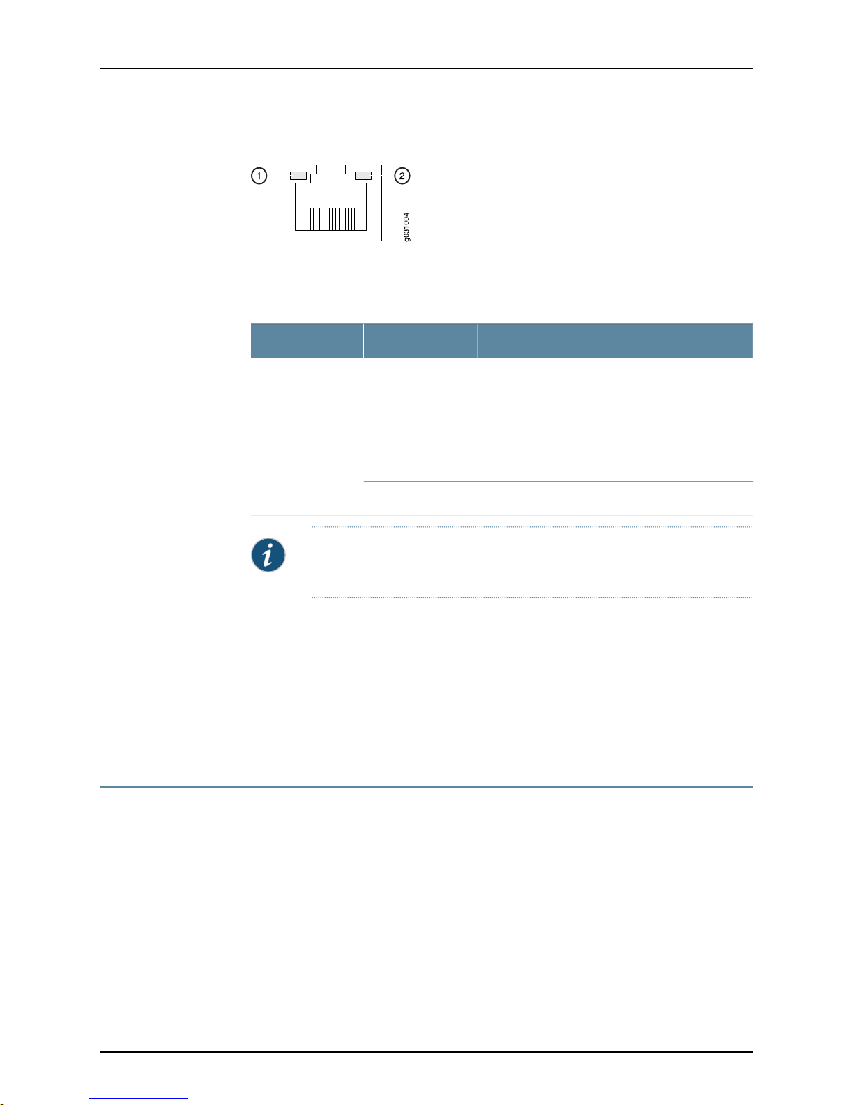
SRX100 Services Gateway Ethernet Port LEDs
On the SRX100 Services Gateway, each Fast Ethernet port has one functional LED on
the left side that indicates Link and Activity. In Figure 2 on page 10, this LED is marked as
1.
9Copyright © 2015, Juniper Networks, Inc.
SRX100 Services Gateway Hardware Guide for B and H Model Numbers
Figure 2: SRX100 Services Gateway Ethernet Port LEDs
The Table 6 on page 10 applies only to the TX/RX/LINK LEDmarked 1. Table 6on page 10
describes the states of this LED.
Table 6: SRX100 Services Gateway Built-In Ethernet Port LEDs
DescriptionStateColorFunction
Related
Documentation
BlinkingGreenTX/RX/LINK
Steady
Link is active. Data
communication is taking
place.
Link is active. No data
communication is taking
place.
Link is inactive.OffUnlit
NOTE: The LED marked as 2 in Figure 2 on page 10 is not functional in this
release.
SRX100 Services Gateway Specifications on page 24•
• SRX100 Services Gateway Front Panel and Back Panel Views on page 13
• SRX100 Services Gateway Built-In Interfaces on page 15
• SRX100 Services GatewayBoot Devices and Dual-Root Partitioning Scheme onpage11
• SRX100 Services Gateway Power Supply on page 10
SRX100 Services Gateway Power Supply
The power supply for the SRX100 Services Gateway is external. You must use the power
supply adapter provided by Juniper Networks to provide power to the services gateway.
Related
Documentation
SRX100 Services Gateway Specifications on page 24•
• SRX100 Services Gateway Front Panel and Back Panel Views on page 13
• SRX100 Services Gateway LEDs on page 7
• SRX100 Services Gateway Built-In Interfaces on page 15
• SRX100 Services GatewayBoot Devices and Dual-Root Partitioning Scheme onpage11
Copyright © 2015, Juniper Networks, Inc.10

Chapter 2: Hardware Component Overview
• Monitoring the SRX100 Services Gateway Power System on page 101
• SRX100 Services Gateway Electrical and Power Requirements on page 30
SRX100 Services Gateway Boot Devices and Dual-Root Partitioning Scheme
This topic includes the following sections:
•
Boot Devices on page 11
•
Dual-Root Partitioning Scheme on page 11
Boot Devices
The SRX100 Services Gateway can boot from the following storage media (in the order
of priority):
•
Internal NAND Flash (default; always present)
•
USB storage key (alternate)
Dual-Root Partitioning Scheme
Dual-root partitions allow the SRX100 Services Gateways to remain functional if there
is file system corruption and facilitate easy recovery of the corrupted file system.
The dual-root partitioning scheme keeps the primary and backup Junos OS images in
two independently bootable root partitions. If the primary root partition becomes
corrupted, the system will be able to boot from the backup Junos OS image located in
the other root partition and remain fully functional.
When the SRX100 Services Gateway powers up, it tries to boot the Junos OS from the
default storage media. If the device fails to boot from the default storage media, it tries
to boot from the alternate storage media. With the dual-root partitioning scheme, the
SRX100 Services Gateway first tries to boot the Junos OS from the primary root partition
and then from the backup root partition on the default storage media. If both primary
and backup root partitions of a media fail to boot, then the device tries to boot from the
next available type of storage media. The SRX100 Services Gateway remains fully
functional even if it boots the Junos OS from the backup root partition of storage media.
The SRX100 Services Gateways that are running Junos OS Release 9.6 or earlier use the
single-root partitioning scheme.Whileupgrading these devicesto Junos OSRelease 10.0,
you can choose to format the storage media with dual-root partitions (strongly
recommended) or retain the existing single-root partitioning.
NOTE: SRX Series devices that ship from the factory with Junos OS Release
10.0 are formatted with the dual-root partitioning scheme.
For instructions on upgrading to Junos OS Release 10.0, see the following topics:
•
Initial Configuration for Security Devices
11Copyright © 2015, Juniper Networks, Inc.

SRX100 Services Gateway Hardware Guide for B and H Model Numbers
•
Monitoring and Troubleshooting for Security Devices
Related
Documentation
• Installation Overview for the SRX100 Services Gateway on page 40
• SRX100 Services Gateway Software Configuration Overview on page 69
Copyright © 2015, Juniper Networks, Inc.12
 Loading...