

Page 1

M120 Internet Router
PIC Guide
Juniper Networks, Inc.
1194 North Mathilda Avenue
Sunnyvale, California 94089
USA
408-745-2000
www.juniper.net
Part Number: 530-024399-01, Revision 1
Page 2

M120 Internet Router PIC Guide
This guide provides an overview and description of the Physical Interface Cards (PICs)
supported by the Juniper Networks M120 Internet router. The PICs are described
alphabetically. Table 1 on page 3 lists the PICs supported by the M120 Internet
router by PIC family.
PICs provide the physical connection to various network media types. The PICs are
mounted on Flexible PIC Concentrators (FPCs), which are inserted into a slot in a
router. A PIC typically occupies a single slot on an FPC. PICs receive incoming packets
from the network and transmit outgoing packets to the network. During this process,
each PIC performs framing and high-speed signaling for its media type. Before
transmitting outgoing data packets, the PICs encapsulate the packets received from
the FPCs. Each PIC is equipped with a media-specific ASIC that performs control
functions tailored to the PIC's media type. For complete information about installing
PICs and transceivers, see the PIC and Transceiver Installation Instructions located at
http://www.juniper.net/techpubs/.
Blank PICs resemble other PICs but do not provide any physical connection or activity.
When a slot is not occupied by a PIC, you must insert a blank PIC to fill the empty
slot and ensure proper cooling of the system.
M120 routers support the Type 1, Type 2, and Type 3 FPCs listed in Table 2 on page
6 and the Compact FPCs (cFPCs) listed in Table 3 on page 6. Table 6 on page 9
provides a PIC/FPC compatibility matrix for the supported PICs for the M120 router.
For a complete list of end-of-life FPCs and end-of-life Enhanced FPCs for M-series
and T-series routing platforms, see the M-series and T-series Routing Platform
End-of-Life FPC Guide located at http://www.juniper.net/techpubs/.
2 ■
Page 3

Table 1: PICs Supported by the M120 Internet Router
ATM2 IQ
Channelized IQ
First JUNOS
SupportPortsPIC Family and Type
Page
208.0R24ATM2 DS3 IQ
228.0R24ATM2 E3 IQ
248.0R22ATM2 OC3/STM1 IQ
278.0R21ATM2 OC12/STM4 IQ
278.0R22ATM2 OC12/STM4 IQ
308.0R21ATM2 OC48/STM16 IQ with SFP
338.0R24Channelized DS3 IQ
358.0R210Channelized E1 IQ
378.0R21Channelized OC3 IQ
408.0R21Channelized OC12 IQ
DS3, E1, E3, and T1
E3 IQ
EIA-530
Fast Ethernet
438.0R21Channelized STM1 IQ
458.0R210Channelized T1 IQ
488.0R24DS3
508.0R24E1
1128.0R24T1
528.0R24E3 IQ
548.0R22EIA-530
568.0R24Fast Ethernet
568.0R28Fast Ethernet
568.0R212Fast Ethernet
568.0R248Fast Ethernet
Gigabit Ethernet
738.0R2110-Gigabit Ethernet with XENPAK
■ 3
Page 4

M120 Internet Router PIC Guide
Table 1: PICs Supported by the M120 Internet Router (continued)
Ethernet IQ
First JUNOS
SupportPortsPIC Family and Type
Page
788.0R2110-Gigabit Ethernet DWDM
608.0R21Gigabit Ethernet with SFP
608.0R22Gigabit Ethernet with SFP
608.0R24Gigabit Ethernet with SFP
608.0R210Gigabit Ethernet with SFP
638.0R21Gigabit Ethernet IQ with SFP
638.0R22Gigabit Ethernet IQ with SFP
Ethernet IQ2
Services
668.0R24Gigabit Ethernet IQ2 with SFP
668.0R28Gigabit Ethernet IQ2 with SFP
668.58Gigabit Ethernet IQ2 with SFP
708.2110-Gigabit Ethernet IQ2 with XFP
128.0R20Adaptive Services II
178.0R20Adaptive Services II Layer 2 Services
158.0R20Adaptive Services II FIPS
808.2R20MultiServices 100
808.20MultiServices 400
808.30MultiServices 500
1148.0R20Tunnel Services
1148.0R20Tunnel Services
1148.0R20Tunnel Services
4 ■
SONET/SDH
838.0R24SONET/SDH OC3c/STM1
878.44SONET/SDH OC3/STM1 (Multi-Rate)
with SFP
878.34SONET/SDH OC3/STM1 (Multi-Rate)
with SFP
Page 5

Table 1: PICs Supported by the M120 Internet Router (continued)
First JUNOS
SupportPortsPIC Family and Type
Page
918.0R21SONET/SDH OC12c/STM4
(Multi-Rate) with SFP
(Multi-Rate) with SFP
(Multi-Rate) with SFP
with XFP
948.41SONET/SDH OC12/STM4
948.34SONET/SDH OC12/STM4
998.0R24SONET/SDH OC48c/STM16 with SFP
1038.31SONET/SDH OC48 /STM16
1088.31SONET/SDH OC192c/STM64 PIC
■ 5
Page 6

M120 Internet Router PIC Guide
FPCs and cFPCs Supported
M120 routers support the FPCs listed in Table 2 on page 6.
Table 2: FPCs Supported by the M120 Router
FPC Model NumberFPC NameFPC Type
A cFPC is a combination of a PIC and an FPC. It contains the interface circuitry and the FPC as a single assembly. Both cFPCs
provide receptacles for XFP optical transceivers. The M120 chassis provides two slots for cFPCs, and supports any combination
of cFPC types. M120 routers support the cFPCs listed in Table 3 on page 6.
Maximum Number
of PICs Supported
per FPC
Maximum Throughput
per FPC
First JUNOS
Release
8.0R24 Gbps4M120-FPC1FPC11
8.0R210 Gbps4M120-FPC2FPC22
8.0R210 Gbps1M120-FPC3FPC33
Table 3: cFPCs Supported by the M120 Router
cFPC Name
cFPC Model
Number
Maximum
Throughput per
cFPC
Release
8.0R210 GbpsM120-cFPC-1XGE-XFP10-Gigabit Ethernet
8.0R210 GbpsM120-cFPC-1OC192-XFPSONET/SDH OC192/STM64
ConnectorFirst JUNOS
Duplex LC/PC (Rx
and Tx)
Duplex LC/PC (Rx
and Tx)
The 10-Gigabit Ethernet cFPC supports the XFPs listed in Table 4 on page 6.
Table 4: Optical Interface Support for 10-Gigabit Ethernet cFPC
number
6 ■ FPCs and cFPCs Supported
10-GBASE-Z10-GBASE-E10-GBASE-L10-GBASE-SParameter
XFP-10G-Z-OC192-LR2XFP-10G-E-OC192-IR2XFP-10G-L-OC192-SR1XFP-10G-STransceiver model
Single-modeSingle-modeSingle-modeMultimodeOptical interface
XFPXFPXFPXFPTransceiver type
IEEE 802.3ae—2002IEEE 802.3ae—2002IEEE 802.3ae—2002Standard
Multivendor
agreement
Page 7

Table 4: Optical Interface Support for 10-Gigabit Ethernet cFPC (continued)
FPCs and cFPCs Supported
10-GBASE-Z10-GBASE-E10-GBASE-L10-GBASE-SParameter
Maximum distance
Average receive power
50/125 MMF cable,
2000 Mhz-Km:
984 feet/300 m
50/125 MMF cable,
500 Mhz-Km:
269 feet/82 m
50/125 MMF cable,
400 Mhz-Km:
217 feet/66 m
62.5/125 MMF cable,
200 Mhz-Km:
108 feet/33 m
62.5/125 MMF cable,
160 Mhz-Km:
85 feet/26 m
840 through 860 nmTransmitter wavelength
–9.9 through
–1.0 dBm
9/125 SMF cable:
6.2 miles/10 km
1260 through
1355 nm
–14.4 through
0.5 dBm
9/125 SMF cable:
24.8 miles/40 km:
Distances greater than
30 km are considered
to be engineered
links.
1530 through
1565 nm
–15.8 through
–1.0 dBm
9/125 SMF cable:
49.6 miles/80 km
1530 through
1565 nm
0 through 4 dBm–4.7 through 4 dBm–4 through 0.5 dBm–4.5 through –1 dBmAverage launch power
–24.0 through
–7.0 dBm
–7 dBm–1.0 dBm0.5 dBm–1.0 dBmReceiver saturation
The SONET/SDH OC192/STM64 cFPC supports the XFPs listed in Table 5 on page 7.
Table 5: Optical Interface Support for SONET/SDH OC192/STM64 cFPC
Intermediate reach
(IR) 2Short reach (SR) 1Parameter
Standard
Telcordia GR-253
OC192 SR1
Telcordia GR-253
OC192 IR2
–24 dBm–15.8 dBm–14.4 dBm–9.9 dBmReceiver sensitivity
Long Reach (LR) 2
XFP-10G-Z-OC192-LR2.XFP-10G-E-OC192-IR2XFP-10G-L-OC192-SR1Transceiver model number
Single-modeSingle-modeSingle-modeOptical interface
XFPXFPXFPTransceiver type
Telcordia GR-253
OC192 LR2
FPCs and cFPCs Supported ■ 7
Page 8

M120 Internet Router PIC Guide
Table 5: Optical Interface Support for SONET/SDH OC192/STM64 cFPC (continued)
Intermediate reach
(IR) 2Short reach (SR) 1Parameter
Long Reach (LR) 2
Maximum distance
Transmitter wavelength
SMF cable:
6.21 miles/10 km
1290 through
1330 nm
SMF cable:
24.8 miles/40 km;
distances greater than
30 km are considered
to be engineered
links.
1565 nm
SMF cable:
49.71 miles/80 km
1530 through 1565 nm1530 through
0 through 4 dBm–1.0. through 2 dBm–6 through –1 dBmAverage launch power
–7 dBm–1.0 dBm–1.0 dBmReceiver saturation
–24 dBm–14 dBm–11 dBmReceiver sensitivity
8 ■ FPCs and cFPCs Supported
Page 9

PIC/FPC Compatibility
Table 6 on page 9 provides a PIC/FPC compatibility matrix for the supported PICs for the M120 router.
Table 6: M120 PIC/FPC Compatibility
ATM2 IQ PICs
PIC/FPC Compatibility
FPC3FPC2FPC1PIC Model NumberNumber of PortsPIC Type
––8.0R2PB-4DS3-ATM24ATM2 DS3 IQ
––8.0R2PB-4E3-ATM24ATM2 E3 IQ
ATM2 OC3/STM1 IQ
ATM2 OC12/STM4 IQ
ATM2 OC12/STM4 IQ
Channelized IQ PICs
T1, DS3, E1, E3 PICs
PB-2OC3-ATM2-MM
2
PB-2OC3-ATM2-SMIR
PB-1OC12-ATM2-MM
1
PB-1OC12-ATM2-SMIR
PB-2OC12-ATM2-MM
2
PB-2OC12-ATM2-SMIR
––8.0R2
––8.0R2
–8.0R2–
–8.0R2–PB-1OC48-ATM2-SFP1ATM2 OC48/STM16 IQ, SFP
––8.0R2PB-4CHDS3-QPP4ChDS3 IQ
––8.0R2PB-10CHE1-RJ48-QPP10ChE1 IQ
––8.0R2PB-1CHOC3-SMIR-QPP1ChOC3 IQ
––8.0R2PB-1CHOC12SMIR-QPP1ChOC12 IQ
––8.0R2PB-1CHSTM1-SMIR-QPP1ChSTM1 IQ
––8.0R2PB-10CHT1-RJ48-QPP10ChT1 IQ
––8.0R2PB-4DS34DS3
E1
E3 IQ PIC
PB-4E1-COAX
4
PB-4E1-RJ48
PIC/FPC Compatibility ■ 9
––8.0R2
––8.0R2PB-4T1-RJ484T1
––8.0R2PB-4E3-QPP4E3 IQ
Page 10

M120 Internet Router PIC Guide
Table 6: M120 PIC/FPC Compatibility (continued)
EIA-530 PIC
Ethernet PICs
FPC3FPC2FPC1PIC Model NumberNumber of PortsPIC Type
––8.0R2PB-2EIA5302EIA-530
––8.0R2PB-4FE-TX4Fast Ethernet
––8.0R2PB-8FE-FX8Fast Ethernet
––8.0R2PB-12FE-TX12Fast Ethernet
–8.0R2–PB-48FE-TX48Fast Ethernet
––8.0R2PB-1GE-SFP1Gigabit Ethernet, SFP
–8.0R2–PB-2GE-SFP2Gigabit Ethernet, SFP
10-Gigabit Ethernet PICs
Ethernet IQ PICs
10-Gigabit Ethernet IQ2 PICs
Ethernet IQ2 PICs
Services PICs
–8.0R2–PB-4GE-SFP4Gigabit Ethernet, SFP
8.0R2––PC-10GE-SFP10Gigabit Ethernet, SFP
8.0R2––PC-1XGE-XENPAK110-Gigabit Ethernet, XENPAK
8.0R2––PC-1XGE-DWDM-CBAND110-Gigabit Ethernet, DWDM
––8.0R2PB-1GE-SFP-QPP1Gigabit Ethernet IQ, SFP
–8.0R2–PB-2GE-SFP-QPP2Gigabit Ethernet IQ, SFP
8.2––PC-1XGE-TYPE3–XFP-IQ2110-Gigabit Ethernet IQ2 PIC, XFP
––8.0R2PB-4GE-TYPE1-SFP-IQ24Gigabit Ethernet IQ2, SFP
–8.0R2–PB-8GE-TYPE2-SFP-IQ28Gigabit Ethernet IQ2, SFP
8.5––PC-8GE-TYPE3-SFP-IQ28Gigabit Ethernet IQ2, SFP
––8.0R2PB-AS20Adaptive Services II (AS)
Adaptive Services II (AS) Layer 2
Services
10 ■ PIC/FPC Compatibility
––8.0R2PB-AS2-LAYER2SERVICES0
––8.0R2PB-AS2-FIPS0Adaptive Services II (AS) FIPS
Page 11

Table 6: M120 PIC/FPC Compatibility (continued)
MultiServices 100
PIC/FPC Compatibility
FPC3FPC2FPC1PIC Model NumberNumber of PortsPIC Type
NOTE: This PIC requires the
710-017980 version or later of
the FPC1.
SONET/SDH PICs
OC3c/STM1
OC12c/STM4
––8.2R2PB-MS-100-10
–8.2–PB-MS-400-20MultiServices 400
8.3––PC-MS-500-30MultiServices 500
––8.0R2PB-TUNNEL-10Tunnel Services
–8.0R2–PB-TUNNEL0Tunnel Services
8.0R2––PC-TUNNEL0Tunnel Services
PB-4OC3-SON-MM
4
––8.0R2
PB-4OC3-SON-SMIR
––8.4PB-4OC3-10C12-SON-SFP4OC3/STM1 (Multi-Rate), SFP
–8.3–PB-4OC3-1OC12-SON2-SFP4OC3/STM1 (Multi-Rate), SFP
PB-1OC12-SON-MM
1
––8.0R2
PB-1OC12-SON-SMIR
––8.4PB-1OC12-SON-SFP1OC12/STM4 (Multi-Rate), SFP
–8.3–PB-4OC3-40C12-SON-SFP4OC12/STM4 (Multi-Rate), SFP
8.0R2––PC-4OC48-SON-SFP4OC48c/STM16
–8.3–PB-1OC48-SON-B-SFP1OC48/STM16 (Multi-Rate), SFP
8.3––PC-1OC192-SON-XFP1OC192c/STM64, XFP
PIC/FPC Compatibility ■ 11
Page 12
M120 Internet Router PIC Guide
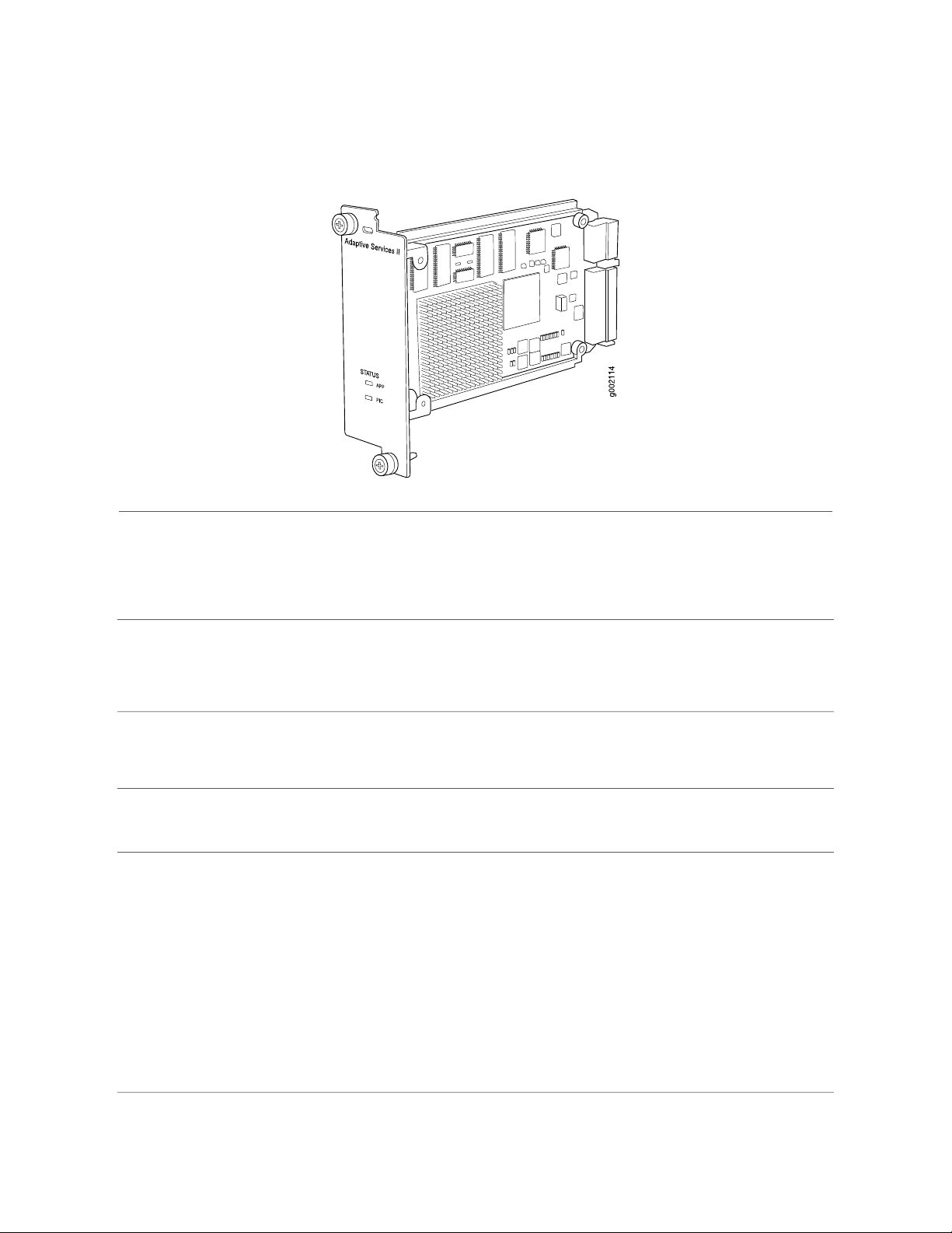
Adaptive Services II PIC
Software release
Description
Hardware features
Software features
LEDs
JUNOS 8.0R2 and later (Type 1)
■
NOTE: This PIC is not supported in JUNOS Release 8.1R1.
Supports tunnel services. This feature is included with the PIC and does not require an
■
individual license.
Individual licenses must be purchased for additional services.
■
Power requirement: 0.4 A @ 48 V (19 W)
■
Support for up to 2000 service sets
■
Active monitoring on up to 1 million flows
■
Support for MTUs up to 9192 bytes for Gigabit Ethernet and SONET interfaces
■
Depending on your JUNOS release and individual licenses, software features for this PIC can
include the features listed in Table 7 on page 13. For more information about the software
features available for services PICs, see the JUNOS Services Interfaces Configuration Guide.
Status LED, one tricolor:
Off—PIC is offline and it is safe to remove it from the chassis.
■
Green—PIC is operating normally.
■
Amber—PIC is initializing.
■
Red—PIC has an error or failure and no further harm can be done by removing it from
■
the chassis.
12 ■ Adaptive Services II PIC
Application LED, one bicolor:
Off—Service is not running.
■
Green—Service is running under acceptable load.
■
Amber—Service is overloaded.
■
Page 13

Adaptive Services II PIC
Table 7: Adaptive Services PICs Software Features Supported by the M120 Router
Software Feature
SYN attacks, ICMP and UDP floods, and
ping-of-death attacks
addresses
5 and version 8 records
version 9 records, based on RFC 3954 (IP v4
templates only)
Adaptive Services II
PIC
Adaptive Services
II Layer 2 Services
PIC
––GRE Key
––GRE dont-fragment
–8.0R2Stateful firewall with packet inspection: detects
–8.0R2Network Address Translation (NAT) for IP
–8.0R2Port Address Translation (PAT) for port numbers
–8.0R2IP Security (IPSec) encryption
–8.0R2Active flow monitoring exports cflowd version
–8.3Active flow monitoring exports flow monitoring
––Passive flow monitoring
––Passive flow collection
IP-IP unicast tunneling
■
GRE unicast tunneling—Supports GRE
■
fragmentation
Protocol Independent Multicast (PIM) sparse
■
mode unicast tunneling
Compressed Real-Time Transport Protocol
■
(CRTP)
––Flow-tap
––Dynamic flow capture
–8.3Real-time performance monitoring
8.0R28.0R2Link services
8.0R28.0R2Tunnel services:
–8.0R2Virtual tunnel interface for Layer 3 VPNs
8.0R28.0R2Layer 2 Tunneling Protocol (L2TP)
8.0R28.0R2Voice services:
Adaptive Services II PIC ■ 13
Page 14

M120 Internet Router PIC Guide
Table 7: Adaptive Services PICs Software Features Supported by the M120
Router (continued)
–8.0R2Encapsulations:
Multilink Frame Relay (MLFR)
■
Multilink Point-to-Point Protocol (MLPP)
■
14 ■ Adaptive Services II PIC
Page 15
Adaptive Services II FIPS PIC
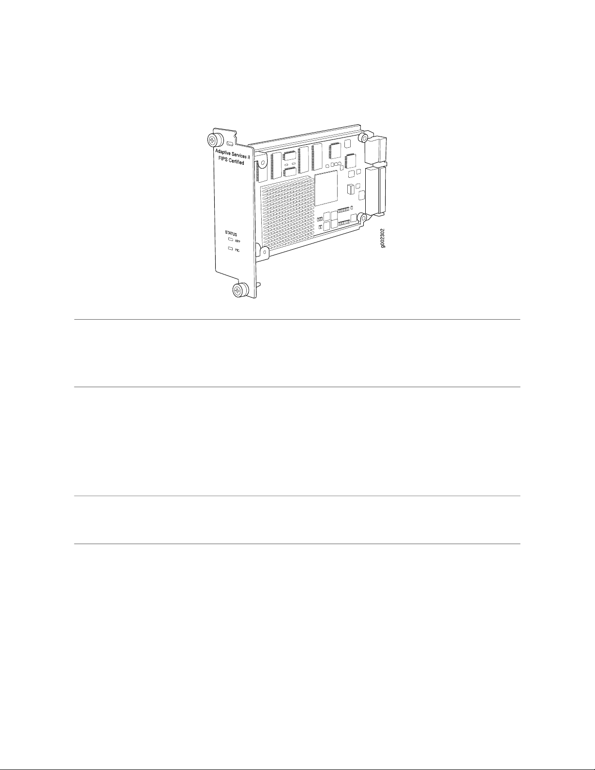
Adaptive Services II FIPS PIC
Software release
Description
Hardware features
JUNOS 8.0R2 and later (Type 1)
■
NOTE: This PIC is not supported in JUNOS Release 8.1R1.
JUNOS-FIPS requires an Adaptive Services II FIPS PIC for external IPSec connections. See
■
the Secure Configuration Guide for Common Criteria and JUNOS-FIPS for more information.
Supports tunnel services. This feature is included with the PIC and does not require an
■
individual license.
Individual licenses must be purchased for additional services such as Network Address
■
Translation (NAT), stateful firewall, intrusion detection services (IDS), IPSec. J-Flow
accounting, and voice services. For information about which services are supported by
PIC and platform type, see the JUNOS Services Interfaces Configuration Guide.
Power requirement: 0.4 A @ 48 V (19 W)
■
Support for up to 2000 service sets
■
Active monitoring on up to 1 million flows
■
Support for MTUs up to 9192 bytes for Gigabit Ethernet and SONET interfaces
■
Adaptive Services II FIPS PIC ■ 15
Page 16

M120 Internet Router PIC Guide
Software features
LEDs
For a list of the software features available for services PICs, see the JUNOS Services Interfaces
Configuration Guide.
Depending on your JUNOS release and individual licenses, software features for this PIC can
include:
Stateful firewall with packet inspection:
■
Detects SYN attacks, ICMP and UDP floods, and ping-of-death attacks
■
NAT for IP addresses
■
Port Address Translation (PAT) for port numbers
■
J-Flow accounting exports cflowd version 5 and version 8 records
■
Tunnel services:
■
IP-IP unicast tunneling
■
GRE unicast tunneling—Supports GRE fragmentation
■
PIM sparse mode unicast tunneling
■
Virtual tunnel interface for Layer 3 VPNs
■
IPSec encryption
■
Voice services:
■
Compressed Real-Time Protocol (CRTP)
■
Encapsulations:
■
Multilink Frame Relay (MLFR)
■
Multilink Point-to-Point Protocol (MLPP)
■
Status LED, one tricolor:
Off—PIC is offline and it is safe to remove it from the chassis.
■
Green—PIC is operating normally.
■
Amber—PIC is initializing.
■
Red—PIC has an error or failure and no further harm can be done by removing it from
■
the chassis.
Application LED, one tricolor:
■
■
■
16 ■ Adaptive Services II FIPS PIC
Off—Service is not running.
Green—Service is running under acceptable load.
Amber—Service is overloaded.
Page 17
Adaptive Services II Layer 2 Services PIC
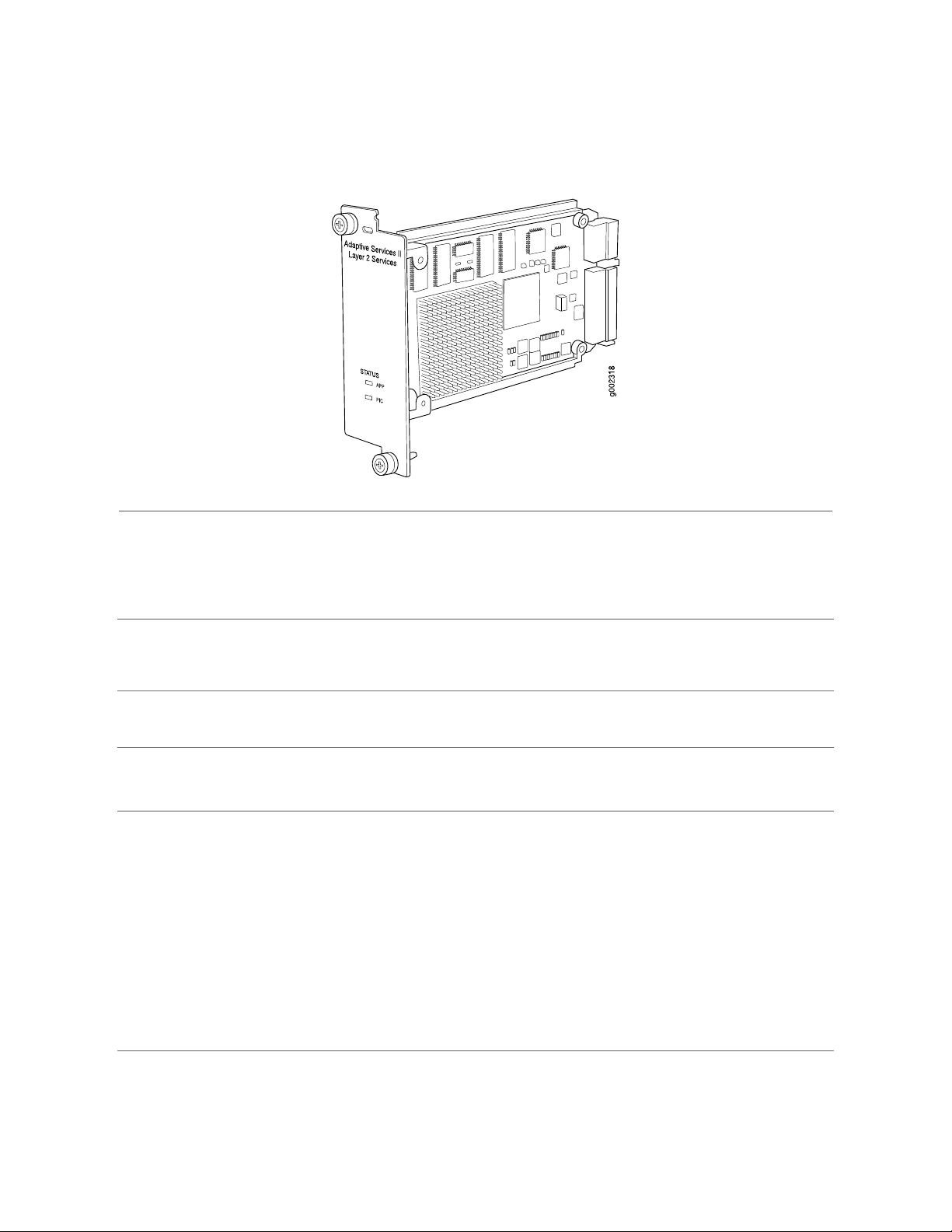
Adaptive Services II Layer 2 Services PIC
Software release
Description
Hardware features
Software features
LEDs
JUNOS 8.0R2 and later (Type 1)
■
NOTE: This PIC is not supported in JUNOS Release 8.1R1.
Supports Layer 2 Service package only. Tunnel services are included with the PIC. Other
■
services require an individual license.
Power requirement: 0.4 A @ 48 V (19 W)
■
Support for up to 2000 service sets
■
Support for MTUs up to 9192 bytes for Gigabit Ethernet and SONET interfaces
■
Depending on your JUNOS release and individual licenses, software features for this PIC can
include the features listed in Table 8 on page 18. For more information about the software
features available for services PICs, see the JUNOS Services Interfaces Configuration Guide.
Status LED, one tricolor:
Off—PIC is offline and it is safe to remove it from the chassis.
■
Green—PIC is operating normally.
■
Amber—PIC is initializing.
■
Red—PIC has an error or failure and no further harm can be done by removing it from
■
the chassis.
Application LED, one bicolor:
Off—Service is not running.
■
Green—Service is running under acceptable load.
■
Amber—Service is overloaded.
■
Adaptive Services II Layer 2 Services PIC ■ 17
Page 18

M120 Internet Router PIC Guide
Table 8: Adaptive Services PICs Software Features
Software Feature
SYN attacks, ICMP and UDP floods, and
ping-of-death attacks
addresses
5 and version 8 records
version 9 records, based on RFC 3954 (IP v4
templates only)
Adaptive Services II
PIC
Adaptive Services
II Layer 2 Services
PIC
––GRE Key
––GRE dont-fragment
–8.0R2Stateful firewall with packet inspection: detects
–8.0R2Network Address Translation (NAT) for IP
–8.0R2Port Address Translation (PAT) for port numbers
–8.0R2IP Security (IPSec) encryption
–8.0R2Active flow monitoring exports cflowd version
–8.3Active flow monitoring exports flow monitoring
––Passive flow monitoring
––Passive flow collection
IP-IP unicast tunneling
■
GRE unicast tunneling—Supports GRE
■
fragmentation
Protocol Independent Multicast (PIM) sparse
■
mode unicast tunneling
Compressed Real-Time Transport Protocol
■
(CRTP)
––Flow-tap
––Dynamic flow capture
–8.3Real-time performance monitoring
8.0R28.0R2Link services
8.0R28.0R2Tunnel services:
–8.0R2Virtual tunnel interface for Layer 3 VPNs
8.0R28.0R2Layer 2 Tunneling Protocol (L2TP)
8.0R28.0R2Voice services:
18 ■ Adaptive Services II Layer 2 Services PIC
Page 19

Adaptive Services II Layer 2 Services PIC
Table 8: Adaptive Services PICs Software Features (continued)
Multilink Frame Relay (MLFR)
■
Multilink Point-to-Point Protocol (MLPP)
■
–8.0R2Encapsulations:
Adaptive Services II Layer 2 Services PIC ■ 19
Page 20
M120 Internet Router PIC Guide
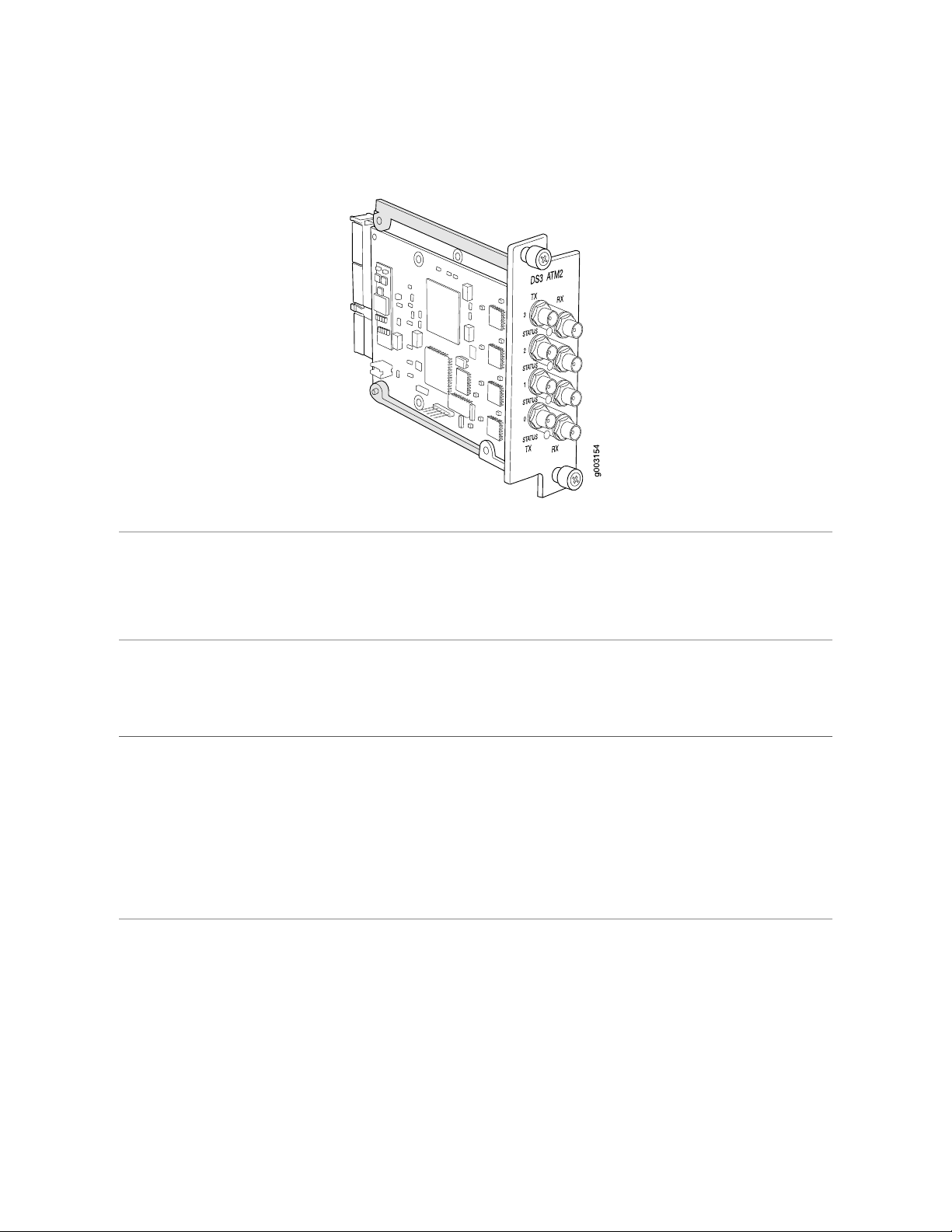
ATM2 DS3 IQ PIC
Software release
Description
Hardware features
JUNOS 8.0R2 and later (Type 1)
■
NOTE: This PIC is not supported in JUNOS Release 8.1R1.
Four DS3 ports
■
Power requirement: 0.41 A @ 48 V (20.0 W)
■
Intelligent queuing (IQ) PICs support fine-grained queuing per logical interface.
■
ATM standards compliant
■
16-MB SDRAM memory for ATM segmentation and reassembly (SAR)
■
ATM switch ID
■
Configurable framing options:
■
C-bit with ATM direct mapping
■
C-bit with Physical Layer Convergence Protocol (PLCP) framing (default)
■
M23 ATM direct mapping
■
M23 with PLCP framing
■
Internal and loop timing
■
20 ■ ATM2 DS3 IQ PIC
Page 21

ATM2 DS3 IQ PIC
Software features
Cables and connectors
LEDs
Per-virtual circuit (VC) and per-virtual path (VP) traffic shaping
■
Unspecified bit rate (UBR) traffic shaping
■
Fine-grained variable bit rate (VBR) traffic shaping
■
Circuit cross-connect (CCC)
■
ATM Inverse Address Resolution Protocol (ARP), which enables routers to automatically
■
learn the IP address of the router on the far end of an ATM permanent virtual circuit
(PVC)
Simple Network Management Protocol (SNMP):
■
Management Information Base (MIB) 2 (RFC 1213)
■
ATM MIB (RFC 1695)
■
SONET MIB
■
AAL5 encapsulations:
■
ATM-VC-MUX
■
ATM-NLPID
■
ATM-Cisco-LLPID
■
ATM-SNAP
■
ATM-CCC-VC-MUX
■
10 ft (3.05 m) posilock SMB to BNC (provided)
■
Four pairs of Rx and Tx coaxial cables
■
One tricolor per port:
Off—Not enabled
■
Green—Online with no alarms or failures
■
Amber—Online with alarms for remote failures
■
Red—Active with a local alarm; router has detected a failure
■
Alarms, errors, and
events
Alarm indication signal (AIS)
■
Far-end block error (FEBE)
■
Frame error
■
Idle code
■
Idle received
■
Local and remote loopback
■
Loss of signal (LOS)
■
Out of frame (OOF)
■
Path parity error
■
Yellow alarm
■
ATM2 DS3 IQ PIC ■ 21
Page 22
M120 Internet Router PIC Guide
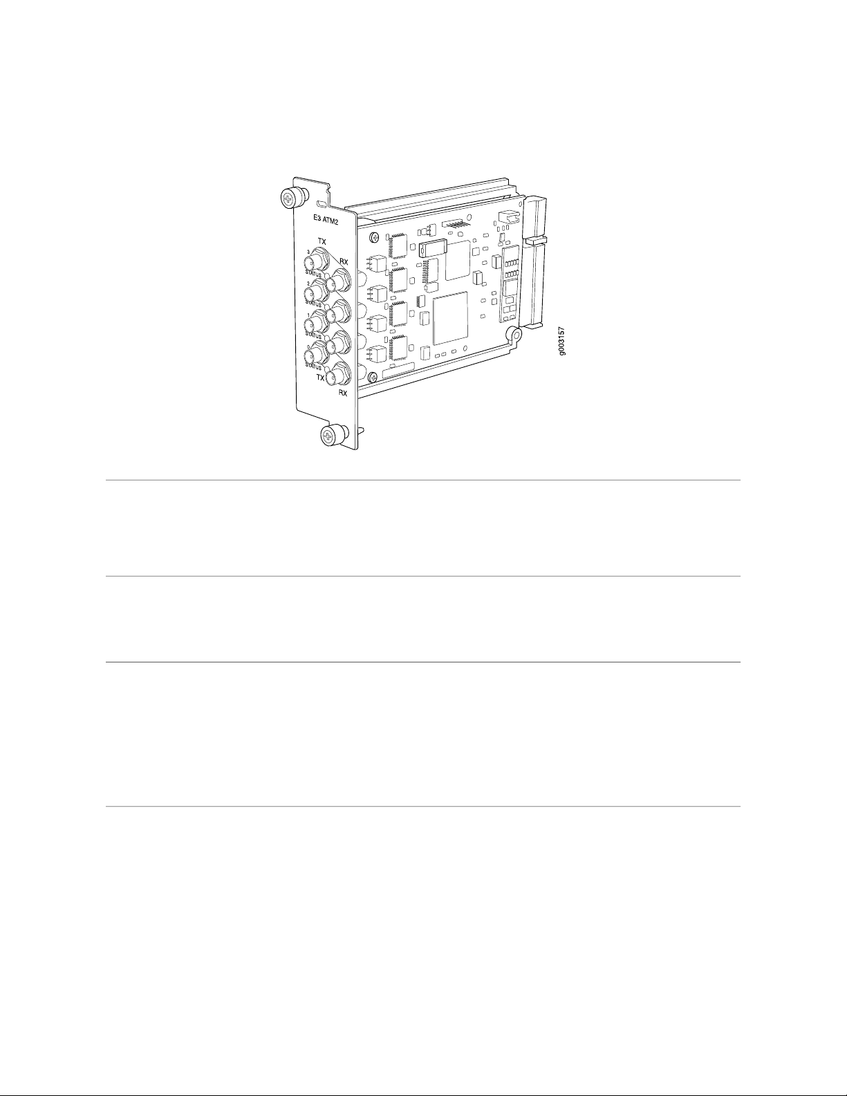
ATM2 E3 IQ PIC
Software release
Description
Hardware features
JUNOS 8.0R2 and later (Type 1)
■
NOTE: This PIC is not supported in JUNOS Release 8.1R1.
Four E3 ports
■
Power requirement: 0.41 A @ 48 V (20 W)
■
Intelligent queuing (IQ) PICs support fine-grained queuing per logical interface
■
ATM standards compliant
■
16-MB SDRAM memory for ATM segmentation and reassembly (SAR)
■
ATM switch ID
■
Configurable framing options:
■
G.751 direct mapping
■
G.751 with PLCP encapsulation (default)
■
G.832 ATM direct mapping
■
Internal and loop timing
■
22 ■ ATM2 E3 IQ PIC
Page 23

ATM2 E3 IQ PIC
Software features
Cables and connectors
LEDs
Per-virtual circuit (VC) and per-virtual path (VP) traffic shaping
■
Unspecified bit rate (UBR) traffic shaping
■
Fine-grained variable bit rate (VBR) traffic shaping
■
Circuit cross-connect (CCC)
■
ATM Inverse Address Resolution Protocol (ARP), which enables routers to automatically
■
learn the IP address of the router on the far end of an ATM permanent virtual circuit
(PVC)
Simple Network Management Protocol (SNMP):
■
Management Information Base (MIB) 2 (RFC 1213)
■
ATM MIB (RFC 1695)
■
SONET MIB
■
AAL5 encapsulations:
■
ATM-VC-MUX
■
ATM-NLPID
■
ATM-Cisco-LLPID
■
ATM-SNAP
■
ATM-CCC-VC-MUX
■
10 ft (3.05 m) posilock SMB to BNC (provided)
■
Four pairs of Rx and Tx coaxial cables
■
One tricolor per port:
Off—Not enabled
■
Green—Online with no alarms or failures
■
Amber—Online with alarms for remote failures
■
Red—Active with a local alarm; router has detected a failure
■
Alarms, errors, and
events
Alarm indication signal (AIS)
■
Frame error
■
Line code violation
■
Local and remote loopback
■
Loss of signal (LOS)
■
Out of frame (OOF)
■
Yellow alarm
■
ATM2 E3 IQ PIC ■ 23
Page 24
M120 Internet Router PIC Guide
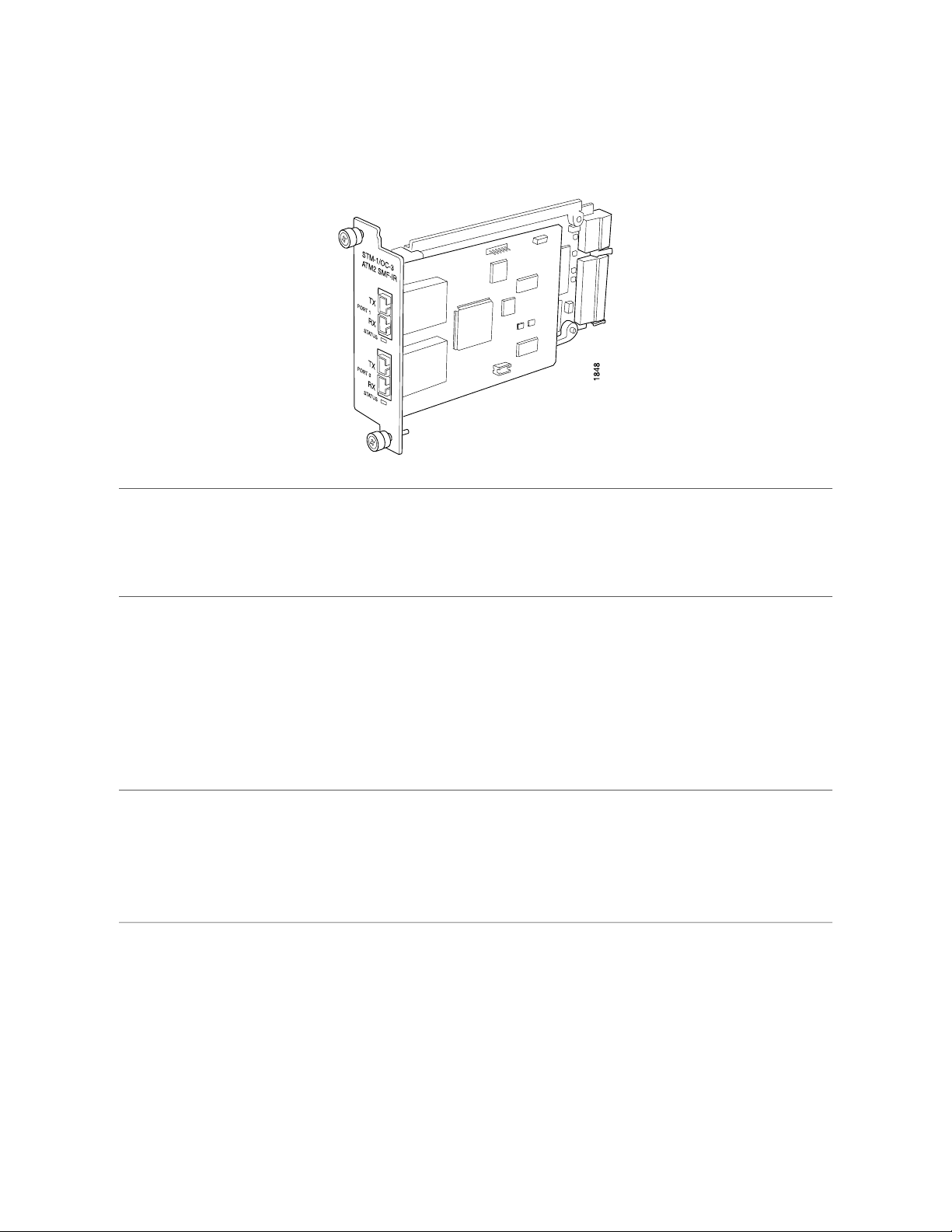
ATM2 OC3/STM1 IQ PIC
Software release
Description
Hardware features
JUNOS 8.0R2 and later (Type 1)
■
NOTE: This PIC is not supported in JUNOS Release 8.1R1.
Two OC3 ports
■
Power requirement: 0.41 A @ 48 V (20 W)
■
Intelligent queuing (IQ) PICs support fine-grained queuing per logical interface
■
Conforms to ANSI T1.105-1991 and T1E1.2/93-020R1
■
ATM and SONET/SDH standards compliant
■
Alarm and event counting and detection
■
Compatible with well-known ATM switches
■
ATM switch ID, which displays the switch IP address and local interface name of the
■
adjacent Fore ATM switches
Single 3010 SAR for segmentation and reassembly into 53 byte ATM cells
■
High-performance parsing of SONET/SDH frames
■
ASIC-based packet segmentation and reassembly (SAR) management and output port
■
queuing
64 MB SDRAM memory for ATM SAR
■
Packet buffering, Layer 2 parsing
■
24 ■ ATM2 OC3/STM1 IQ PIC
Page 25

ATM2 OC3/STM1 IQ PIC
Software features
Cables and connectors
LEDs
Circuit cross-connect (CCC) for leveraging ATM access networks
■
User-configurable virtual circuit (VC) and virtual path (VP) support
■
Support for idle cell or unassigned cell transmission
■
OAM fault management processes alarm indication signal (AIS), remote defect indicator
■
(RDI) cells, and loop cells
Point-to-point and point-to-multipoint mode Layer 2 counters per VC and per VP
■
Local and remote loopback
■
ATM Inverse Address Resolution Protocol (ARP), which enables routers to automatically
■
learn the IP address of the router on the far end of an ATM permanent virtual circuit
(PVC)
Simple Network Management Protocol (SNMP):
■
Management Information Base (MIB) 2 (RFC 1213)
■
ATM MIB (RFC 1695)
■
SONET MIB
■
Unspecified bit rate (UBR), non-real-time variable bit rate (VBR), and constant bit rate
■
(CBR) traffic shaping
Per-VC or per-VP traffic shaping
■
Support for F4 OAM cells
■
Support for 16 bit VCI range
■
Duplex SC/PC connector (RX and TX)
■
Optical interface support—See Table 9 on page 25
■
One tricolor per port:
Off—Not enabled
■
Green—Online with no alarms or failures
■
Amber—Online with alarms for remote failures
■
Red—Active with a local alarm; router has detected a failure
■
Alarms, errors, and
events
Alarm indication signal (AIS-L, AIS-P)
■
Bit error rate signal degrade (BERR-SD), bit error rate signal fail (BERR-SF)
■
Bit interleaved parity errors B1, B2, B3
■
Errored seconds (ES-S, ES-L, ES-P), far-end bit errors REI-L, REI-P (CV-LFE, CV-PFE),
■
far-end errored seconds (ES-LFE, ES-PFE), far-end severely errored seconds (SES-LFE,
SES-PFE), far-end unavailable seconds (UAS-LFE, UAS-PFE)
Loss of cell delineation (LOC), loss of frame (LOF), loss of pointer (LOP-P), loss of signal
■
(LOS)
Payload mismatch (PLM-P), payload unequipped (UNEQ-P)
■
Remote defect indication (RDI-L, RDI-P)
■
Severely errored framing (SEF), severely errored framing seconds (SEFS-S), severely
■
errored seconds (SES-S, SES-L, SES-P), unavailable seconds (UAS-L, UAS-P)
Table 9: Optical Interface Support for ATM2 OC3 IQ PICs
MultimodeIntermediate Reach (IR)Parameter
MultimodeSingle-modeOptical interface
FixedFixedTransceiver type
ATM2 OC3/STM1 IQ PIC ■ 25
Page 26

M120 Internet Router PIC Guide
Table 9: Optical Interface Support for ATM2 OC3 IQ PICs (continued)
MultimodeIntermediate Reach (IR)Parameter
Multivendor agreementTelcordia GR-253Standard
1.2 miles/2 km9.3 miles/15 kmMaximum distance
wavelength
1270 through 1380 nm1260 through 1360 nmTransmitter
–20 through –14 dBm–15 through –8 dBmAverage launch power
–14 dBm–8 dBmReceiver saturation
–30 dBm–28 dBmReceiver sensitivity
26 ■ ATM2 OC3/STM1 IQ PIC
Page 27
ATM2 OC12/STM4 IQ PICs
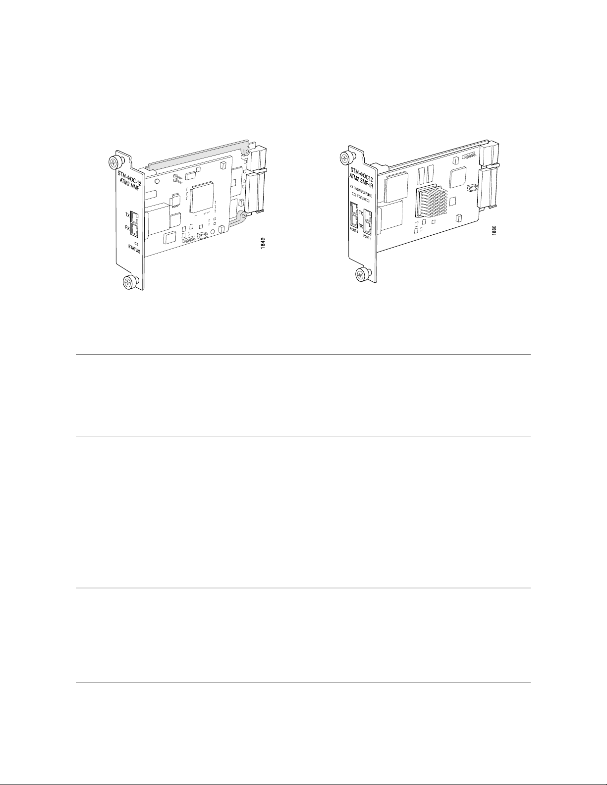
ATM2 OC12/STM4 IQ PICs
Left: 1-port ATM2 OC12/STM4 IQ PIC; Right: 2-port ATM2 OC12/STM4 IQ PIC
Software release
Description
Hardware features
1-port: JUNOS 8.0R2 and later (Type 1)
■
2-port: JUNOS 8.0R2 and later (Type 2)
■
NOTE: These PICs are not supported in JUNOS Release 8.1R1.
One or two OC12 ports
■
Power requirement:
■
1-port: 0.41 A @ 48 V (20 W)
■
2-port: 0.52 A @ 48 V (25 W)
■
Intelligent queuing (IQ) PICs support fine-grained queuing per logical interface
■
Conforms to ANSI T1.105-1991 and T1E1.2/93-020R1
■
Complies with ATM and SONET/SDH standards
■
Alarm and event counting and detection
■
Compatible with well-known ATM switches
■
ATM switch ID, which displays the switch IP address and local interface name of the
■
adjacent Fore ATM switches
ATM2 IQ 1-port OC12 PICs have one 3010 SAR for segmentation and reassembly into
■
53-byte ATM cells; ATM2 IQ 2-port OC12 PICs have dual 3010 SAR
High-performance parsing of SONET/SDH frames
■
ASIC-based packet segmentation and reassembly (SAR) management and output port
■
queuing
64 MB SDRAM memory for ATM SAR
■
Packet buffering, Layer 2 parsing
■
ATM2 OC12/STM4 IQ PICs ■ 27
Page 28

M120 Internet Router PIC Guide
Software features
Cables and connectors
LEDs
Circuit cross-connect for leveraging ATM access networks
■
User-configurable virtual circuit (VC) and virtual path (VP) support
■
Support for idle cell or unassigned cell transmission
■
OAM fault management processes alarm indication signal (AIS), remote defect indication
■
(RDI), and loop cells
Point-to-point and point-to-multipoint mode Layer 2 counters per VC and per VP
■
Local and remote loopback
■
ATM Inverse ARP, which enables routers to automatically learn the IP address of the
■
router on the far end of an ATM PVC
Simple Network Management Protocol (SNMP):
■
Management Information Base (MIB) 2 (RFC 1213)
■
ATM MIB (RFC 1695)
■
SONET MIB
■
Unspecified bit rate (UBR), non-real-time variable bit rate (VBR), and constant bit rate
■
(CBR) traffic shaping
Per-VC or per-VP traffic shaping
■
Support for F4 OAM cells
■
Support for 16-bit VCI range
■
Duplex SC/PC connector (Rx and Tx)
■
Optical interface support—See Table 10 on page 28
■
One tricolor per port:
Off—Not enabled
■
Green—Online with no alarms or failures
■
Amber—Online with alarms for remote failures
■
Red—Active with a local alarm; router has detected a failure
■
Alarms, errors, and
events
Alarm indication signal (AIS-L, AIS-P)
■
Bit error rate signal degrade (BERR-SD), bit error rate signal fail (BERR-SF)
■
Bit interleaved parity errors B1, B2, B3
■
Errored seconds (ES-S, ES-L, ES-P), far-end bit errors REI-L, REI-P (CV-LFE, CV-PFE),
■
far-end errored seconds (ES-LFE, ES-PFE), far-end severely errored seconds (SES-LFE,
SES-PFE), far-end unavailable seconds (UAS-LFE, UAS-PFE)
Loss of cell delineation (LOC), loss of frame (LOF), loss of pointer (LOP-P), loss of signal
■
(LOS)
Payload mismatch (PLM-P), payload unequipped (UNEQ-P)
■
Remote defect indication (RDI-L, RDI-P)
■
Severely errored framing (SEF), severely errored framing seconds (SEFS-S), severely
■
errored seconds (SES-S, SES-L, SES-P), unavailable seconds (UAS-L, UAS-P)
Table 10: Optical Interface Support for ATM2 OC12/STM4 IQ PICs
Multimode TransceiverIntermediate Reach (IR) TransceiverParameter
MultimodeSingle-modeOptical interface
FixedFixedTransceiver type
28 ■ ATM2 OC12/STM4 IQ PICs
Page 29

Table 10: Optical Interface Support for ATM2 OC12/STM4 IQ PICs (continued)
Multimode TransceiverIntermediate Reach (IR) TransceiverParameter
Multivendor agreementTelcordia GR-253Standard
546.8 yards/500 m9.3 miles/15 kmMaximum distance
1270 through 1380 nm1274 through 1356 nmTransmitter wavelength
–20 through –14 dBm–15 through –8 dBmAverage launch power
–14 dBm–8 dBmReceiver saturation
–26 dBm–28 dBmReceiver sensitivity
ATM2 OC12/STM4 IQ PICs
ATM2 OC12/STM4 IQ PICs ■ 29
Page 30
M120 Internet Router PIC Guide
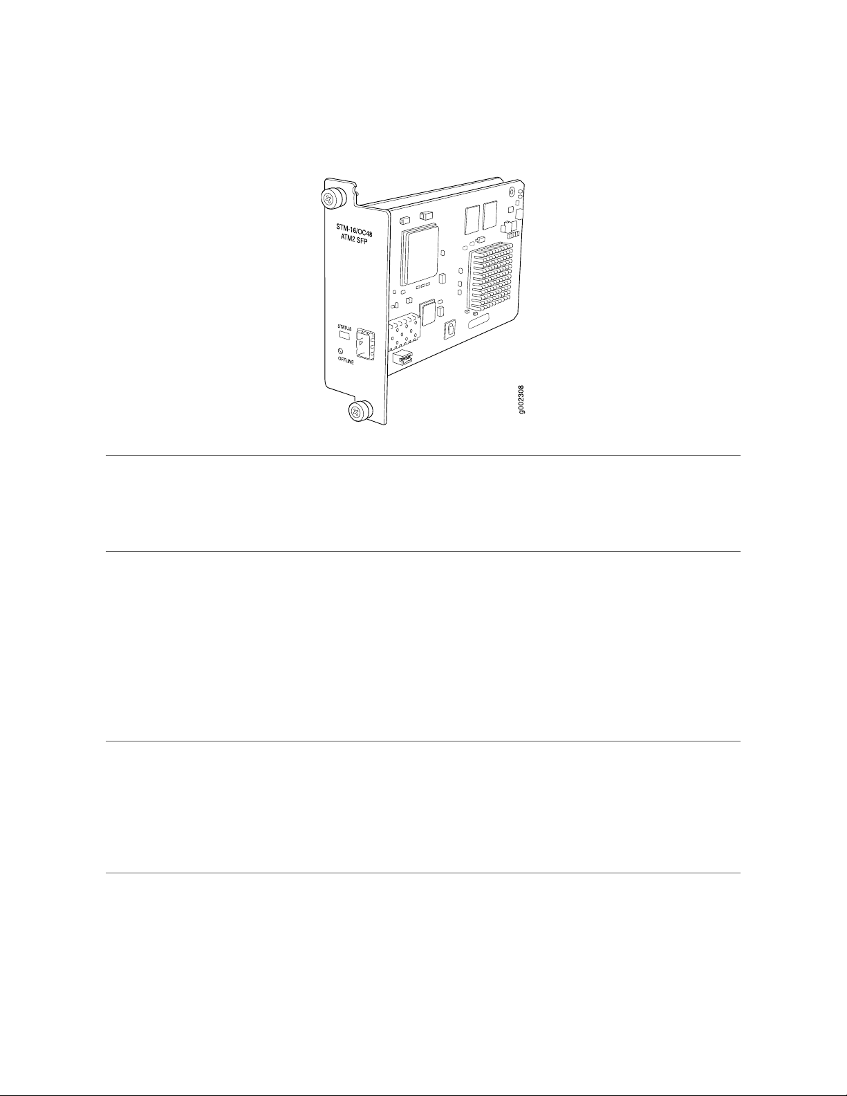
ATM2 OC48/STM16 IQ PIC with SFP
Software release
Description
Hardware features
JUNOS 8.0R2 and later (Type 2)
■
NOTE: This PIC is not supported in JUNOS Release 8.1R1.
One OC48 port
■
Power requirement: 0.41 A @ 48 V ( 20 W)
■
Intelligent queuing (IQ) PICs support fine-grained queuing per logical interface.
■
Conforms to ANSI T1.105-1991 and T1E1.2/93-020R1
■
Complies with ATM and SONET/SDH standards
■
Alarm and event counting and detection
■
Compatible with well-known ATM switches
■
ATM switch ID, which displays the switch IP address and local interface name of the
■
adjacent Fore ATM switches
Optical interface support—see Table 11 on page 31
■
ATM2 IQ 1-port OC48 PICs have one 3010 SAR for segmentation and reassembly into
■
53-byte ATM cells.
High-performance parsing of SONET/SDH frames
■
ASIC-based packet segmentation and reassembly (SAR) management and output port
■
queuing
64-MB SDRAM memory for ATM SAR
■
Packet buffering, Layer 2 parsing
■
30 ■ ATM2 OC48/STM16 IQ PIC with SFP
Page 31

ATM2 OC48/STM16 IQ PIC with SFP
Software features
LEDs
Multiprotocol Label Switching (MPLS) circuit cross-connect for leveraging ATM access
■
networks
User-configurable virtual circuit (VC) and virtual path (VP) support
■
Support for idle cell or unassigned cell transmission
■
OAM fault management processes alarm indication signal (AIS), remote defect indicator
■
(RDI), and loop cells
Point-to-point and point-to-multipoint mode Layer 2 counters per VC and per VP
■
Local and remote loopback
■
ATM Inverse ARP, which enables routers to automatically learn the IP address of the
■
router on the far end of an ATM PVC
Simple Network Management Protocol (SNMP):
■
Management Information Base (MIB) 2 (RFC 1213)
■
ATM MIB (RFC 1695)
■
SONET MIB
■
Unspecified bit rate (UBR), non-real-time variable bit rate (VBR), and constant bit rate
■
(CBR) traffic shaping
Per-VC or per-VP traffic shaping
■
Support for F4 OAM cells
■
Support for 16-bit VCI range
■
Duplex LC/PC connector (RX and TX)Cables and connectors
■
One tricolor per port:
Off—Not enabled
■
Green—Online with no alarms or failures
■
Amber—Online with alarms for remote failures
■
Red—Active with a local alarm; router has detected a failure
■
Alarms, errors, and
events
Table 11: Optical Interface Support for ATM2 IQ OC48 PICs
Alarm indication signal (AIS-L, AIS-P)
■
Bit error rate signal degrade (BERR-SD), bit error rate signal fail (BERR-SF)
■
Bit interleaved parity errors B1, B2, B3
■
Errored seconds (ES-S, ES-L, ES-P), far-end bit errors REI-L, REI-P (CV-LFE, CV-PFE),
■
far-end errored seconds (ES-LFE, ES-PFE), far-end severely errored seconds (SES-LFE,
SES-PFE), far-end unavailable seconds (UAS-LFE, UAS-PFE)
Loss of cell delineation (LOC), loss of frame (LOF), loss of pointer (LOP-P), loss of signal
■
(LOS)
Payload mismatch (PLM-P), payload unequipped (UNEQ-P)
■
Remote defect indication (RDI-L, RDI-P)
■
Severely errored framing (SEF), severely errored framing seconds (SEFS-S), severely
■
errored seconds (SES-S, SES-L, SES-P), unavailable seconds (UAS-L, UAS-P)
Single-Mode Intermediate ReachPIC Type
Single-modeOptical interface
SFPTransceiver type
ATM2 OC48/STM16 IQ PIC with SFP ■ 31
Page 32

M120 Internet Router PIC Guide
Table 11: Optical Interface Support for ATM2 IQ OC48 PICs (continued)
Single-Mode Intermediate ReachPIC Type
Telcordia GR-253Standard
9.3 miles/15 kmMaximum distance
wavelength
1274 through 1356 nmTransmitter
–15 through –8 dBmAverage launch power
–8 dBmReceiver saturation
–28 dBmReceiver sensitivity
32 ■ ATM2 OC48/STM16 IQ PIC with SFP
Page 33

Channelized DS3 IQ PIC
Channelized DS3 IQ PIC
Software release
Description
Hardware features
JUNOS 8.0R2 and later (Type 1)
■
NOTE: This PIC is not supported in JUNOS Release 8.1R1.
Four DS3 ports
■
Power requirement: 0.32 A @ 48 V (15.6 W)
■
Intelligent queuing (IQ) PICs support fine-grained queuing per logical interface
■
Channelization: DS3, DS0
■
Data service unit (DSU) functionality
■
Subrate and scrambling:
■
Digital Link/Quick Eagle
■
Kentrox
■
Larscom
■
ADTRAN
■
Verilink
■
B3ZS line encoding
■
M13 or C-bit parity
■
Full bit error rate test (BERT)
■
Local and remote loopback testing
■
Channelized DS3 IQ PIC ■ 33
Page 34

M120 Internet Router PIC Guide
Software features
LEDs
Alarms, errors, and
events
Quality of service (QoS) per channel: weighted round-robin (WRR), random early detection
■
(RED), weighted random early detection (WRED)
Simple Network Management Protocol (SNMP): DS1 MIB, DS3 MIB
■
Dynamic, arbitrary channel configuration
■
Encapsulations:
■
High-Level Data Link Control (HDLC)
■
Frame Relay
■
Circuit cross-connect (CCC)
■
Translational cross-connect (TCC)
■
Point-to-Point Protocol (PPP)
■
Standard DS3 BNC coaxial cable interfacesCables and connectors
■
One tricolor per port:
Off—Not enabled
■
Green—Online with no alarms or failures
■
Amber—Online with alarms for remote failures
■
Red—Active with a local alarm; router has detected a failure
■
Alarm indication signal (AIS)
■
Excessive zeros (EXZ)
■
Far-end block error (FEBE)
■
Frame error
■
Idle code, Idle received
■
Line code violation (LCV)
■
Loss of signal (LOS)
■
Out of frame (OOF)
■
Parity bit (P-bit) disagreements
■
Path parity error
■
Yellow alarm bit (X-bit) disagreements
■
(counters)
34 ■ Channelized DS3 IQ PIC
Layer 2 per-queue and per-channel packet and byte countersInstrumentation
■
Page 35

Channelized E1 IQ PIC
Channelized E1 IQ PIC
Software release
Description
Hardware features
Software features
JUNOS 8.0R2 and later (Type 1)
■
NOTE: This PIC is not supported in JUNOS Release 8.1R1.
Ten E1 ports
■
Power requirement: 0.15 A @ 48 V (7.2 W)
■
Intelligent queuing (IQ) PICs support fine-grained queuing per logical interface.
■
Channelization: E1, DS0
■
Data service unit (DSU) functionality
■
Ports configurable as clear channel E1 interfaces with 2.048-Mbps connectivity
■
Supports unframed E1 G.703 and G.704 framing modes
■
Supports HDB3 line coding
■
CRC4 configurable
■
Local and remote loopback testing
■
Quality of service (QoS) per channel: weighted round-robin (WRR), random early detection
■
(RED), weighted random early detection (WRED)
Simple Network Management Protocol (SNMP): E1 MIB, DS0 MIB
■
Dynamic, arbitrary channel configuration
■
Full bit error rate test (BERT)
■
Encapsulations:
■
High-Level Data Link Control (HDLC)
■
Frame Relay
■
Circuit cross-connect (CCC)
■
Translational cross-connect (TCC)
■
Point-to-Point Protocol (PPP)
■
Channelized E1 IQ PIC ■ 35
Page 36

M120 Internet Router PIC Guide
120-ohm RJ-48CCables and connectors
■
LEDs
Alarms, errors, and
events
(counters)
One bicolor per E1 port:
Off—Port not enabled
■
Green—Physical E1 link is up; individual subchannels can be down
■
Red—Physical E1 link is down
■
Alarm indication signal (AIS)
■
Loss of frame (LOF)
■
Out of frame (OOF)
■
Failed signal rate (FSR)
■
Layer 2 per-queue and per-channel packet and byte countersInstrumentation
■
36 ■ Channelized E1 IQ PIC
Page 37

Channelized OC3 IQ PIC
Channelized OC3 IQ PIC
Software release
Description
Hardware features
JUNOS 8.0R2 and later (Type 1)
■
NOTE: This PIC is not supported in JUNOS Release 8.1R1.
One OC3 port
■
Power requirement: 0.39 A @ 48 V (8.6 W)
■
Intelligent queuing (IQ) PICs support fine-grained queuing per logical interface.
■
Channelization: DS3, DS1, DS0
■
Optical interface support — see Table 12 on page 38
■
Subrate and scrambling:
■
Digital Link/Quick Eagle
■
Kentrox
■
Larscom
■
Adtran
■
Verilink
■
Packet buffering, Layer 2 parsing
■
M13/C-bit parity encoding
■
DS3 far-end alarm and control (FEAC) channel support
■
Local and remote loopback testing
■
Channelized OC3 IQ PIC ■ 37
Page 38

M120 Internet Router PIC Guide
Software features
LEDs
Alarms, errors, and
events
Quality of Service (QoS) per channel: weighted round-Robin (WRR), random early drop
■
(RED), weighted random early drop (WRED)
Simple Network Management Protocol (SNMP): OC3 MIB, DS3 MIB, T1 MIB
■
Dynamic, arbitrary channel configuration
■
Full Bit Error Rate Testing (BERT)
■
Encapsulations:
■
High-Level Data Link Control (HDLC)
■
Frame Relay
■
Circuit cross-connect (CCC)
■
Translational cross-connect (TCC)
■
Point-to-Point Protocol (PPP)
■
Duplex SC/PC connector (Rx and Tx); single-mode fiber intermediate-reach fiberCables and connectors
■
One tricolor per port:
Off—Not enabled
■
Green—Online with no alarms or failures
■
Amber—Online with alarms for remote failures
■
Red—Active with a local alarm; router has detected a failure
■
Alarm indication signal (AIS-L, AIS-P)
■
Bit error rate signal degrade (BERR-SD), bit error rate signal fail (BERR-SF)
■
Bit interleaved parity errors B1, B2, B3 (CV-S, CV-L, CV-P)
■
Errored seconds (ES-S, ES-L, ES-P), far-end bit errors REI-L, REI-P (CV-LFE, CV-PFE),
■
far-end Block error (FEBE), far-end errored seconds (ES-LFE, ES-PFE), far-end severely
errored seconds (SES-LFE, SES-PFE), far-end unavailable seconds (UAS-LFE, UAS-PFE)
Frame error
■
Idle code, idle received
■
Loss of frame (LOF), loss of pointer (LOP-P), loss of signal (LOS)
■
Out of frame (OOF)
■
Payload mismatch (PLM-P), payload unequipped (UNEQ-P)
■
Parity bit (P-bit) disagreements
■
Path parity error
■
Remote defect indication (RDI-L, RDI-P)
■
Severely errored framing (SEF), severely errored framing seconds (SEFS-S), Sseverely
■
errored seconds (SES-S, SES-L, SES-P), unavailable seconds (UAS-L, UAS-P)
Yellow alarm bit (X-bit) disagreements
■
Table 12: Optical Interface Support for Channelized OC3 IQ PICs
38 ■ Channelized OC3 IQ PIC
Intermediate Reach (IR)PIC Type
Single-modeOptical interface
Telcordia GR-253Standard
9.3 miles/15 kmMaximum distance
1274 through 1356 nmTransmit wavelength
Page 39

Table 12: Optical Interface Support for Channelized OC3 IQ PICs (continued)
Intermediate Reach (IR)PIC Type
–15 through –8 dBmAverage launch power
–8 dBmReceiver saturation
–28 dBmReceiver sensitivity
Channelized OC3 IQ PIC
Channelized OC3 IQ PIC ■ 39
Page 40

M120 Internet Router PIC Guide
Channelized OC12 IQ PIC
Software release
Description
Hardware features
JUNOS 8.0R2 and later (Type 1)
■
NOTE: This PIC is not supported in JUNOS Release 8.1R1.
One OC12 port
■
Power requirement: 0.23 A @ 48 V (10.8 W)
■
Intelligent queuing (IQ) PICs support fine-grained queuing per logical interface
■
Channelization: OC3, DS3, DS1, DS0
■
Subrate and scrambling:
■
Digital Link/Quick Eagle
■
Kentrox
■
Larscom
■
ADTRAN
■
Verilink
■
Packet buffering, Layer 2 parsing
■
M13/C-bit parity encoding
■
DS3 far-end alarm and control (FEAC) channel support
■
Local and remote loopback testing
■
40 ■ Channelized OC12 IQ PIC
Page 41

Channelized OC12 IQ PIC
Software features
Cables and connectors
LEDs
Alarms, errors, and
events
Quality of service (QoS) per channel: weighted round-robin (WRR), random early detection
■
(RED), weighted random early detection (WRED)
Simple Network Management Protocol (SNMP): OC3 MIB, DS3 MIB, T1 MIB
■
Dynamic, arbitrary channel configuration
■
Full bit error rate test (BERT)
■
Encapsulations:
■
High-Level Data Link Control (HDLC)
■
Frame Relay
■
Circuit cross-connect (CCC)
■
Translational cross-connect (TCC)
■
Point-to-Point Protocol (PPP)
■
Duplex SC/PC connector (Rx and Tx); single-mode fiber
■
Optical interface support—See Table 13 on page 41
■
One tricolor per port:
Off—Not enabled
■
Green—Online with no alarms or failures
■
Amber—Online with alarms for remote failures
■
Red—Active with a local alarm; router has detected a failure
■
Alarm indication signal (AIS-L, AIS-P)
■
Bit error rate signal degrade (BERR-SD), bit error rate signal fail (BERR-SF)
■
Bit interleaved parity errors B1, B2, B3 (CV-S, CV-L, CV-P)
■
Errored seconds (ES-S, ES-L, ES-P), far-end bit errors REI-L, REI-P (CV-LFE, CV-PFE),
■
far-end block error (FEBE), far-end errored seconds (ES-LFE, ES-PFE), far-end severely
errored seconds (SES-LFE, SES-PFE), far-end unavailable seconds (UAS-LFE, UAS-PFE)
Frame error
■
Idle code, Idle received
■
Loss of frame (LOF), loss of pointer (LOP-P), loss of signal (LOS)
■
Out of frame (OOF)
■
Payload mismatch (PLM-P), payload unequipped (UNEQ-P)
■
Parity bit (P-bit) disagreements
■
Path parity error
■
Remote defect indication (RDI-L, RDI-P)
■
Severely errored framing (SEF), severely errored framing seconds (SEFS-S), severely
■
errored seconds (SES-S, SES-L, SES-P), unavailable seconds (UAS-L, UAS-P)
Yellow alarm bit (X-bit) disagreements
■
Layer 2 per-queue and per-channel packet and byte countersInstrumentation
■
(counters)
Table 13: Optical Interface Support for Channelized OC12 IQ PICs
Intermediate Reach (IR)Parameter
Single-modeOptical interface
Channelized OC12 IQ PIC ■ 41
Page 42

M120 Internet Router PIC Guide
Table 13: Optical Interface Support for Channelized OC12 IQ PICs (continued)
Intermediate Reach (IR)Parameter
Telcordia GR-253Standard
9.3 miles/15 kmMaximum distance
1274 through 1356 nmTransmitter wavelength
–15 through –8 dBmAverage launch power
–8 dBmReceiver saturation
–28 dBmReceiver sensitivity
42 ■ Channelized OC12 IQ PIC
Page 43

Channelized STM1 IQ PIC
Channelized STM1 IQ PIC
Software release
Description
Hardware features
Software features
JUNOS 8.0R2 and later (Type 1)
■
NOTE: This PIC is not supported in JUNOS Release 8.1R1.
One STM1 port
■
Power requirement: 0.39 A @ 48 V (18.6 W)
■
Intelligent queuing (IQ) PICs support fine-grained queuing per logical interface
■
Channelization: STM1c, fractional E1, framed and unframed DS0
■
Packet buffering, Layer 2 parsing
■
Local and remote loopback testing
■
Quality of service (QoS) per channel: weighted round-robin (WRR), random early detection
■
(RED), weighted random early detection (WRED)
SNMP: SONET/SDH MIB, T1/E1 MIB
■
Dynamic, arbitrary channel configuration
■
Full bit error rate test (BERT) patterns at E1 and DS0 levels
■
Encapsulations:
■
High-Level Data Link Control (HDLC)
■
Frame Relay
■
Circuit cross-connect (CCC)
■
Translational cross-connect (TCC)
■
Point-to-Point Protocol (PPP)
■
LEDs
Duplex SC/PC connector (Rx and Tx); single-mode intermediate-reach fiberCables and connectors
■
One tricolor per port:
Off—Not enabled
■
Green—Online with no alarms or failures
■
Amber—Online with alarms for remote failures
■
Red—Active with a local alarm; router has detected a failure
■
Channelized STM1 IQ PIC ■ 43
Page 44

M120 Internet Router PIC Guide
Alarms, errors, and
events
(counters)
Alarm indication signal (AIS-L, AIS-P)
■
Bit error rate signal degrade (BERR-SD), bit error rate signal fail (BERR-SF)
■
Bit interleaved parity errors B1, B2, B3 (CV-S, CV-L, CV-P)
■
Errored seconds (ES-S, ES-L, ES-P), far-end bit errors REI-L, REI-P (CV-LFE, CV-PFE),
■
far-end errored seconds (ES-LFE, ES-PFE), far-end severely errored seconds (SES-LFE,
SES-PFE), far-end unavailable seconds (UAS-LFE, UAS-PFE)
Loss of frame (LOF), loss of pointer (LOP-P), loss of signal (LOS)
■
Payload mismatch (PLM-P), payload unequipped (UNEQ-P)
■
Remote defect indication (RDI-L, RDI-P)
■
Severely errored framing (SEF), severely errored framing seconds (SEFS-S), severely
■
errored seconds (SES-S, SES-L, SES-P), unavailable seconds (UAS-L, UAS-P)
Layer 2 per-queue and per-channel packet and byte countersInstrumentation
■
44 ■ Channelized STM1 IQ PIC
Page 45

Channelized T1 IQ PIC
Channelized T1 IQ PIC
Software release
Description
JUNOS 8.0R2 and later (Type 1)
■
NOTE: This PIC is not supported in JUNOS Release 8.1R1.
Ten T1 ports
■
Power requirement: 0.15 A @ 48 V (7.2 W)
■
Intelligent queuing (IQ) PICs support fine-grained queuing per logical interface.
■
Channelization: T1, FT1, NxDS0
■
Channelized T1 IQ PIC ■ 45
Page 46

M120 Internet Router PIC Guide
Hardware features
Data service unit (DSU) and channel service unit (CSU) functionality
■
Ports configurable as clear channel T1 interfaces with 1.544-Mbps connectivity
■
Framing: Superframe (SF or D4) and Extended Superframe (ESF)
■
Supports B8ZS (bipolar 8-zero substitution) and AMI (alternate mark inversion) line coding
■
Local, remote, and payload loopback testing
■
ANSI T1.403 loopback support:
■
Responds to embedded loopback commands upon receipt of an FDL command
■
from remote end with loopup and loopdown at both line and payload level
Insertion of loopback commands enables remote CSU/NIU/Smartjack to enter
■
loopback and loopdown at both the line and payload level (ANSI and Telcordia)
Inband loopback support:
■
Responds to inband loopback commands at both the line and payload level (ANSI
■
and Telcordia)
Insertion of inband loopback commands at both the line and payload level (ANSI
■
and Telcordia)
Clocking support of external (line) and internal
■
Buildout support of the following ranges:
■
0 through 132 (Line buildout is from 1 through 132 feet)
■
133 through 265 (Line buildout is from 133 through 265 feet)
■
266 through 398 (Line buildout is from 266 through 398 feet)
■
399 through 531 (Line buildout is from 399 through 531 feet)
■
532 through 655 (Line buildout is from 532 through 655 feet)
■
Software features
LEDs
Quality of service (QoS) per channel: weighted round-robin (WRR), random early detection
■
(RED), weighted random early detection (WRED)
SNMP: T1 MIB and DS0 MIB
■
Dynamic, arbitrary channel configuration
■
Full bit error rate test (BERT) patterns at T1 and DS0 levels
■
Encapsulations:
■
High-Level Data Link Control (HDLC)
■
Frame Relay
■
Circuit cross-connect (CCC)
■
Translational cross-connect (TCC)
■
Point-to-Point Protocol (PPP)
■
120-ohm RJ-48C connector (female)Cables and connectors
■
One tricolor per port:
Off—Not enabled
■
Green—Online with no alarms or failures
■
Amber—Online with alarms for remote failures
■
Red—Active with a local alarm; router has detected a failure
■
46 ■ Channelized T1 IQ PIC
Page 47

Channelized T1 IQ PIC
Alarms, errors, and
events
Instrumentation
(counters)
Alarm indication signal (AIS)
■
Remote defect indication (RDI)
■
Loss of frame (LOF)
■
Loss of signal (LOS)
■
Bipolar violation (BPV)
■
Excessive zero (EXZ)
■
Line code violation (LCV)
■
Error seconds (ES)
■
Severely errored seconds (SES)
■
Severely errored frames (SEF)
■
Bit error event (BEE)
■
Layer 2 per-queue and per-channel packet and byte counters
■
24–hour history or error counter updated at 15–minute intervals
■
Channelized T1 IQ PIC ■ 47
Page 48

M120 Internet Router PIC Guide
DS3 PIC
Software release
Description
Hardware features
JUNOS 8.0R2 and later (Type 1)
■
NOTE: This PIC is not supported in JUNOS Release 8.1R1.
Four DS3 ports
■
Power requirement: 0.47 A @ 48 V (22.5 W)
■
Integrated DSU interoperability with leading DSU vendors
■
High-performance throughput on each port at speeds up to 44.736 Mbps, full duplex
■
C-bit framing
■
B3ZS line encoding
■
Subrate and scrambling:
■
Digital Link
■
Kentrox
■
Larscom
■
Per-port rate policing on input
■
Per-port rate shaping on output
■
Packet buffering, Layer 2 parsing
■
48 ■ DS3 PIC
Page 49

DS3 PIC
Software features
LEDs
Alarms, errors, and
events
DS3 functionality:
■
C-bit framing
■
B3ZS line encoding
■
DS3 diagnostics and loopback control
■
DS3 alarm and event counting and detection
■
Per-packet counts and byte counts
■
Local and remote loopback testing, as well as BERT testing per DS3
■
DS3 far-end alarm and control (FEAC) channel support
■
Encapsulations:
■
High-Level Data Link Control (HDLC)
■
Frame Relay
■
Circuit cross-connect (CCC)
■
Point-to-Point Protocol (PPP)
■
Custom 10-ft (3.05-m) posilock SMB to BNC male cable, separate Rx and Tx (provided)Cables and connectors
■
One tricolor per port:
Off—Not enabled
■
Green—Online with no alarms or failures
■
Amber—Online with alarms for remote failures
■
Red—Active with a local alarm; router has detected a failure
■
Alarm indication signal (AIS)
■
Bit error rate test (BERT) functionality on PIC (you can configure one DS3 channel in
■
BERT mode and configure the remaining channels to transmit and receive normal traffic)
Equipment failure (does not affect service)
■
Far-end block error (FEBE)
■
Frame error
■
Idle code, Idle received
■
Local and remote loopback
■
Loss of signal (LOS)
■
Out of frame (OOF)
■
Parity bit (P-bit) disagreements
■
Path parity error
■
Yellow alarm bit (X-bit) disagreements
■
DS3 PIC ■ 49
Page 50

M120 Internet Router PIC Guide
E1 PICs
Software release
Description
Hardware features
Left: E1 RJ-48 PIC; Right: E1 Coaxial PIC
JUNOS 8.0R2 and later (Type 1)
■
NOTE: These PICs are not supported in JUNOS Release 8.1R1.
Four E1 or coaxial ports
■
Power requirement: 0.08 A @ 48 V (3.74 W)
■
Two versions:
■
4-port, 120-ohm, RJ-48
■
4-port, 75-ohm, coaxial
■
Onboard DSU functionality for E1 connectivity
■
High-performance throughput on each port at speeds up to 2.048 Mbps, full duplex
■
Maximum transmission units (MTUs) of up to 4500 bytes
■
Per-interface diagnostics and loopback control
■
Per-interface shaping on output
■
Per-interface alarm and event counting and detection
■
HDB3 line coding
■
4-bit CRC for G.704 framed mode
■
Per-port loop timing
■
Balanced and unbalanced modes
■
Packet buffering, Layer 2 parsing
■
Full bit error rate test (BERT)
■
50 ■ E1 PICs
Page 51

E1 PICs
Software features
Cables and connectors
LEDs
Integrated support for G.703 unframed mode and G.704 framed mode with CRC; this
■
feature is user-configurable
NOTE: The G.704 implementation supports speeds slower than 2.048 Mbps; multiple channels
within a single E1 interface are not supported.
Configurable clock source: Internal or loop
■
Encapsulations:
■
High-Level Data Link Control (HDLC)
■
Frame Relay
■
Circuit cross-connect (CCC)
■
Point-to-Point Protocol (PPP)
■
Two versions:
■
Four RJ-48 connectors (one per port)
■
Four coaxial connectors
■
Custom 10-ft (3.05-m) posilock to BNC male cable, separate Rx and Tx
■
One tricolor per port:
Off—Not enabled
■
Green—Online with no alarms or failures
■
Amber—Online with alarms for remote failures
■
Red—Active with a local alarm; router has detected a failure
■
Alarms, errors, and
events
Alarm indication signal (AIS)
■
Bipolar violations
■
Excessive zeros
■
Far-end block errors (FEBE, E-bit errors)
■
Loss of frame (LOF), Loss of signal (LOS)
■
Local and remote loopback diagnostics
■
Yellow alarm bit (X-bit) disagreements
■
E1 PICs ■ 51
Page 52

M120 Internet Router PIC Guide
E3 IQ PIC
Software release
Description
Hardware features
JUNOS 8.0R2 and later (Type 1)
■
NOTE: This PIC is not supported in JUNOS Release 8.1R1.
Four E3 ports
■
Power requirement: 0.38 A @ 48 V (18 W)
■
Intelligent queuing (IQ) PICs support fine-grained queuing per logical interface
■
Clear-channel (34.368-Mbps) and subrate E3
■
Unframed or ITU G.751 framing
■
Data service unit (DSU) functionality
■
Subrate and scrambling:
■
Digital Link/Quick Eagle
■
Kentrox
■
HDB3 line encoding
■
Full bit error rate test (BERT)
■
Local and remote loopback testing
■
52 ■ E3 IQ PIC
Page 53

E3 IQ PIC
Software features
LEDs
Quality of service (QoS) per port: weighted round-robin (WRR), random early detection
■
(RED), weighted random early detection (WRED)
Simple Network Management Protocol (SNMP): E3 MIB, QoS MIB
■
Input policing and output shaping
■
Provider-side rate limiting
■
Full data link connection identifier (DLCI) range with sparse channel numbering
■
Per-DLCI queues with weighted deficit round-robin and strict priority
■
Encapsulations:
■
High-Level Data Link Control (HDLC)
■
Frame Relay
■
Circuit cross-connect (CCC)
■
Translational cross-connect (TCC)
■
Point-to-Point Protocol (PPP)
■
JUNOS Release 7.0 or later is required to configure graceful Routing Engine switchover
■
(GRES).
Standard E3 BNC coaxial cable interfacesCables and connectors
■
One tricolor per port:
Off—Not enabled
■
Green—Online with no alarms or failures
■
Amber—Online with alarms for remote failures
■
Red—Active with a local alarm; router has detected a failure
■
Alarms, errors, and
events
(counters)
Alarm indication signal (AIS)
■
Equipment failure (does not affect service)
■
Frame error
■
Line code violation
■
Loss of signal (LOS)
■
Out of frame (OOF)
■
Yellow alarm bit (A-bit) disagreements
■
Layer 2 per-queue packet and byte countersInstrumentation
■
E3 IQ PIC ■ 53
Page 54

M120 Internet Router PIC Guide
EIA-530 PIC
Software release
Description
Hardware features
JUNOS 8.0R2 and later (Type 1)
■
NOTE: This PIC is not supported in JUNOS Release 8.1R1.
Two EIA-530, X.21 or V.35 serial ports
■
Power requirement: 0.07 A @ 48 V (3.4 W)
■
Configured as data terminal equipment (DTE) ports
■
Resynchronization signal
■
Receives clock rates up to 16 Mbps
■
Local, data communications equipment (DCE) local, and DTE remote loopbacks
■
54 ■ EIA-530 PIC
Page 55

EIA-530 PIC
Software features
Cables and connectors
Supports four queues per port
■
Random early detection (RED)
■
Transmitter Signal Element Timing is looped from the timing received on the Transmitted
■
Signal Element DCE. EIA-530 ports support the ability to invert the Transmit Data Element.
The EIA-530 ports support the following rates:
2.048 Mbps
■
2.341 Mbps
■
2.731 Mbps
■
3.277 Mbps
■
4.09 Mbps
■
5.461 Mbps
■
8.192 Mbps
■
16.384 Mbps
■
V.35 ports support up to 2.048 Mbps
■
X.21 ports support up to 10 Mbps
■
Encapsulations:
■
High-Level Data Link Control (HDLC)
■
Frame Relay
■
Circuit cross-connect (CCC)
■
Translational cross-connect (TCC)
■
Point-to-Point Protocol (PPP)
■
Two DB-25 male connectors (one per port, included with PIC)
■
V.35 requires an EIA-530 to V.35 cable and connects to a V.35 DTE 34-pin Winchester
■
type male cable (one per port)
X.21 requires an EIA-530 to X.21 cable and connects to a X.21 DTE DB-15 male cable
■
LEDs
Instrumentation
(counters)
Three bicolor per port:
Data set ready (DSR):
■
Green—DSR is detected or ignored
■
Red—DSR expected but not present
■
Data carrier detect (DCD):
■
Green—DCD is detected or ignored
■
Red—DCD expected but not present
■
Resynchronization:
■
Green—Keepalives are being received
■
Red—Data terminal ready (DTR) toggled from low to high (resynchronization pulses
■
are being sent)
Per-port packet and byte counters
■
Resynchronization counters:
■
Number of resynchronizations initiated
■
Time of last resynchronization
■
EIA-530 PIC ■ 55
Page 56

M120 Internet Router PIC Guide
Fast Ethernet PICs
Left: 4-Port Fast Ethernet PIC; Right: 8-Port Fast Ethernet PIC
Left: 12-Port Fast Ethernet PIC; Right: 48-Port Fast Ethernet PIC
56 ■ Fast Ethernet PICs
Page 57

VHDCI to RJ-21 Cable
Fast Ethernet PICs
Software release
Description
Hardware features
4-port: JUNOS 8.0R2 and later (Type 1)
■
8-port: JUNOS 8.0R2 and later (Type 1)
■
12-port: JUNOS 8.0R2 and later (Type 1)
■
48-port: JUNOS 8.0R2 and later (Type 2)
■
NOTE: These PICs are not supported in JUNOS Release 8.1R1.
4 100Base-TX ports
■
8 100Base-FX ports
■
12 100Base-TX ports
■
48 100Base-TX ports
■
Power requirement:
■
4-port: 0.14 A @ 48 V (6.8 W)
■
8-port: 0.26 A @ 48 V (12.5 W)
■
12-port: 0.23 A @ 48 V (11 W)
■
48-port: 0.69 A @ 48 V (33.3 W)
■
High-performance throughput on each port at speeds up to 100 Mbps
■
Source and destination Media Access Control (MAC) address filtering
■
RMON EtherStats packet buffering
■
802.3 Ethernet standard compliant
■
4-port PICs support MTUs of up to 9,192 bytes; 8-port, 12-port, and 48-port PICs support
■
MTUs of up to 1,532 bytes
4-port PICs support 1,024 802.1Q VLANs per port; 8-port, 12-port, and 48-port PICs
■
support 16 802.1Q VLANs per port
Software features
Autosensing full-duplex and half-duplex modes
■
Virtual Router Redundancy Protocol (VRRP)
■
802.1q virtual LANs (VLANs)
■
Circuit cross-connect (CCC) VLAN
■
Fast Ethernet PICs ■ 57
Page 58

M120 Internet Router PIC Guide
Cables and connectors
LEDs
4-port PIC:
Connector: Two-pair, Category 5 unshielded twisted-pair connectivity through an RJ-45
■
connector
Pinout: MDI noncrossover
■
8-port PIC:
Connector: MT-RJ female
■
FX optical interface—see Table 14 on page 59
■
12-port PIC:
Connector: One very High Density Connector Interface (VHDCI) to RJ-21 cable that
■
connects to an RJ-45 patch panel
48-port PIC:
VHDCI to RJ-21 cables that connect to an RJ-45 patch panel
■
Four VHDCI connectors that each service 12 10/100 ports
■
NOTE: Each of the four connectors on a Fast Ethernet 48-port PIC can support a maximum
of approximately 800 Mbps. However, this constitutes oversubscription. Use this PIC only in
environments that can support this level of oversubscription.
Status LED, one bicolor:
Off—PIC ports not enabled
■
Green—PIC is operating normally
■
Red—PIC has an error or failure
■
4-port PIC—One pair of port LEDs:
Link LED—If green, the port is online; if there is no light, the port is down
■
RX LED—If flashing green, the port is receiving data; if there is no light, the port might
■
be on but is not receiving data
8-port PIC—one pair of port LEDs per port:
Port link LED—If green, the port is online; if there is no light, the port is down
■
NOTE: The Link LED remains lit on the 8-port PIC when the port is down.
Port RX LED—If flashing green, the port is receiving data; if there is no light, the port
■
might be on, but is not receiving data
12-port PIC—one port LED per port:
Green—100-Mbps link established
■
Flashing green—100-Mbps activity
■
Yellow—10-Mbps link established
■
Flashing yellow—10-Mbps activity
■
Off—No link present
■
NOTE: The port LEDs remains lit on the 12-port PIC when the ports are down.
58 ■ Fast Ethernet PICs
Page 59

48-port PIC—does not have port LEDs. To check port status on a 48-port PIC, use the show
interfaces fe-fpc/pic/port command. For more information about this command, see the JUNOS
Network Interfaces Configuration Guide.
Table 14: Optical Interface Support for Fast Ethernet PICs
FX Interface for 8-PortParameter
MultimodeOptical interface
62.5/125 MMF cable: 1.24 miles /2 kmMaximum distance
1,270 to 1,380 nmWavelength
–20 to –14 dBmAverage launch power
–14 dBmReceiver saturation
Fast Ethernet PICs
–34 dBmReceiver sensitivity
Fast Ethernet PICs ■ 59
Page 60

M120 Internet Router PIC Guide
Gigabit Ethernet PICs with SFP
Left: 1-Port Gigabit Ethernet PIC; Right: 2-Port Gigabit Ethernet PIC
Left: 4-Port Gigabit Ethernet PIC; Right: 10-Port Gigabit Ethernet PIC
60 ■ Gigabit Ethernet PICs with SFP
Page 61

Gigabit Ethernet PICs with SFP
Software release
Description
Hardware features
Software features
1-port: JUNOS 8.0R2 and later (Type 1)
■
2-port: JUNOS 8.0R2 and later (Type 2)
■
4-port: JUNOS 8.0R2 and later (Type 2)
■
10-port: JUNOS 8.0R2 and later (Type 3)
■
NOTE: These PICs are not supported in JUNOS Release 8.1R1.
One, two, four, or ten Gigabit Ethernet ports
■
Power requirement:
■
1-port: 0.15 A @ 48 V (7.3 W)
■
2-port: 0.25 A @ 48 V (11.9 W)
■
4-port: 0.50 A @ 48 V (23.8 W)
■
10-port: 0.62 A @ 48 V (29.9 W)
■
Supports large Ethernet frame sizes for more efficient throughput across the intra-POP
■
network
High-performance throughput on each port at speeds up to 1 Gbps
■
Autonegotiation between Gigabit Ethernet circuit partners
■
Full-duplex mode
■
Maximum transmission units (MTUs) of up to 9192 bytes
■
Virtual Router Redundancy Protocol (VRRP) support
■
802.1q virtual LANs (VLANs) support
■
960 destination MAC filters per port
■
Optical diagnostics and related alarms on the 2-port, 4-port, and 10-port PICs (JUNOS
■
8.2 and later)
Flexible Ethernet encapsulation on the 1-port, 2-port, and 4-port PICs
■
Multiple tag protocol identifiers (TPID) support on the 1-port, 2-port, and 4-port PICs
■
Source MAC learning on the 1-port, 2-port, and 4-port PICs
■
MAC accounting and policing—Dynamic local address learning of source MAC addresses
■
on the 1-port, 2-port, and 4-port PICs
Cables and connectors
NOTE: The 10-port Gigabit Ethernet PIC with SFP does not support MAC accounting and
policing, MAC learning, TPID, or flexible Ethernet encapsulation.
You can install any transceiver supported by the PIC. For information about installing
■
and removing transceivers, see the PIC and Transceiver Installation Instructions.
Fiber-optic SFP transceivers:
■
Duplex LC/PC connector (Rx and Tx)
■
Optical interface support—See Table 15 on page 62
■
1000Base-T SFP transceivers:
■
Connector: Four-pair, Category 5 shielded twisted-pair connectivity through an RJ-45
■
connector
Pinout: MDI crossover
■
Length: 328 ft/100 m
■
NOTE: Do not install Gigabit Ethernet SFPs in the SONET/SDH port. The port will not recognize
the SFP.
Gigabit Ethernet PICs with SFP ■ 61
Page 62

M120 Internet Router PIC Guide
LEDs
Status LED, one bicolor:
Off—PIC is not enabled
■
Green—PIC is operating normally
■
Red—PIC has an error or failure
■
Port LEDs, one pair per port:
Link—If green, the port is online; if there is no light, the port is down
■
Activity—If flashing green, the port is receiving data; if there is no light, the port might
■
be on but is not receiving data
Table 15: Optical Interface Support for Gigabit Ethernet PICs with SFP
Maximum distance
62.5/125 MMF cable:
656 ft/200 m
50/125 MMF cable:
1640 ft/500 m
9/125 SMF cable:
6.2 miles/10 km
62.5/125 and 50/125
MMF cable:
1804.5 ft/550 m
1000Base-LH1000Base-LX1000Base-SXParameter
Single-modeSingle-modeMultimodeOptical interface
SFPSFPSFPTransceiver type
9/125 SMF cable:
43.5 miles/70 km
1355 through 1580 nm1270 through 1355 nm770 through 860 nmTransmitter wavelength
–3 through +3 dBm–11.5 through –3 dBm–9.5 through 0 dBmAverage launch power
–20 through –3 dBm–19 through –3 dBm–17 through 0 dBmAverage receive power
–3 dBm–3 dBm0 dBmReceiver saturation
–20 dBm–19 dBm–17 dBmReceiver sensitivity
62 ■ Gigabit Ethernet PICs with SFP
Page 63

Gigabit Ethernet IQ PICs with SFP
Gigabit Ethernet IQ PICs with SFP
Software release
Description
Hardware features
Software features
Left: 1-port Gigabit Ethernet IQ PIC; Right: 2-port Gigabit Ethernet IQ PIC
1-port: JUNOS 8.0R2 and later (Type 1)
■
2-port: JUNOS 8.0R2 and later (Type 2)
■
NOTE: These PICs are not supported in JUNOS Release 8.1R1.
One or two Gigabit Ethernet ports
■
Power requirement: 0.46 A @ 48 V (22 W)
■
Intelligent queuing (IQ) PICs support fine-grained queuing per logical interface
■
Optical interface support—See Table 16 on page 64
■
High-performance throughput on each port at speeds up to 1 Gbps
■
Full-duplex mode
■
Large MTUs of up to 9192 bytes
■
Optical diagnostics and related alarms
■
Quality of service (QoS) per channel: weighted round-robin (WRR), random early detection
■
(RED), weighted random early detection (WRED)
Virtual Router Redundancy Protocol (VRRP) support
■
802.1q virtual LANs (VLANs)
■
VLAN stacking and rewriting
■
Flexible Ethernet encapsulation
■
MAC policing, accounts, and filters
■
JUNOS Release 7.0 or later is required to configure graceful Routing Engine switchover
■
(GRES).
Gigabit Ethernet IQ PICs with SFP ■ 63
Page 64

M120 Internet Router PIC Guide
Cables and connectors
LEDs
You can install any transceiver supported by the PIC. For information about installing
■
and removing transceivers, see the PIC and Transceiver Installation Instructions.
Fiber-optic SFP transceivers:
■
Duplex LC/PC connector (Rx and Tx)
■
Optical interface support—see Table 16 on page 64
■
1000Base-T SFP transceivers:
■
Connector: Four-pair, Category 5 shielded twisted-pair connectivity through an RJ-45
■
connector
Pinout: MDI crossover
■
Length: 328 ft/100 m
■
NOTE: Do not install SONET/SDH OC48c/STM16 SFPs in the Gigabit Ethernet port. The port
will not recognize the SFP.
Status LED, one tricolor:
Off—Not enabled
■
Green—Online with no alarms or failures
■
Amber—Online with alarms for remote failures
■
Red—Active with a local alarm; router has detected a failure
■
NOTE: The green status LED is lit on the 2-port Gigabit Ethernet IQ PIC when at least one
port is online.
Port LEDs, one per port:
Off—Port is down
■
Green—Link is established
■
Table 16: Optical Interface Support for Gigabit Ethernet IQ PICs with SFP
1000Base-LH1000Base-LX1000Base-SXParameter
Single-modeSingle-modeMultimodeOptical interface
SFPSFPSFPTransceiver type
IEEE 802.3—1998IEEE 802.3—1998Standard
Multivendor
agreement
Maximum distance
62.5/125 MMF cable:
656 ft/200 m
50/125 MMF cable:
1640 ft/500 m
9/125 SMF cable:
6.2 miles/10 km
62.5/125 or 50/125
MMF cable:
9/125 SMF cable:
43.5 miles/70 km
1804.5 ft/550 m
wavelength
770 through 860 nmTransmitter
1270 through 1355
nm
–9.5 through 0 dBmAverage launch power
1480 through 1580
nm
–3 through +3 dBm–11.5 through –3
dBm
64 ■ Gigabit Ethernet IQ PICs with SFP
Page 65

Gigabit Ethernet IQ PICs with SFP
Table 16: Optical Interface Support for Gigabit Ethernet IQ PICs with SFP (continued)
1000Base-LH1000Base-LX1000Base-SXParameter
power
–20 through –3 dBm–19 through –3 dBm–17 through 0 dBmAverage receive
–3 dBm–3 dBm0 dBmReceiver saturation
–20 dBm–19 dBm–17dBmReceiver sensitivity
Gigabit Ethernet IQ PICs with SFP ■ 65
Page 66

M120 Internet Router PIC Guide
Gigabit Ethernet IQ2 PICs with SFP
Left: 4-port Gigabit Ethernet IQ2 PIC (Type 1); Right: 8-port Gigabit Ethernet IQ2 PIC (Type 2)
66 ■ Gigabit Ethernet IQ2 PICs with SFP
Page 67

g002378
Gigabit Ethernet IQ2 PICs with SFP
Software release
Description
Hardware features
Center: 8-port Gigabit Ethernet IQ2 PIC (Type 3)
4-port: JUNOS 8.0R2 and later (Type 1)
■
8-port: JUNOS 8.0R2 and later (Type 2)
■
8-port: JUNOS 8.5 and later (Type 3)
■
NOTE: These PICs are not supported in JUNOS Release 8.1R1.
Four or eight Gigabit Ethernet ports
■
Power requirement:
■
4-port: 0.65 A @ 48 V (31W)
■
8-port (Type 2): 0.89 A @ 48 V (42.5W)
■
8-port (Type 3): 1.25 A @48 V (60 W)
■
High-performance throughput on each port:
■
4-port with SFP: speeds up to 1 Gbps
■
8-port with SFP: speeds up to 4 Gbps
■
Full-duplex mode
■
Large maximum transmission units (MTUs) of up to 9192 bytes
■
Gigabit Ethernet IQ2 PICs with SFP ■ 67
Page 68

M120 Internet Router PIC Guide
Software features
Cables and connectors
Intelligent handling of oversubscribed traffic for Type 1 and Type 2 PICs
■
Optical diagnostics and related alarms
■
Quality of service (QoS) per channel: weighted round-robin (WRR), random early detection
■
(RED), weighted random early detection (WRED)
Virtual Router Redundancy Protocol (VRRP) support
■
Hierarchical shaping
■
Fine-grained queuing and shaping per logical interface at both ingress and egress
■
802.1q virtual LANs (VLANs)
■
VLAN stacking and rewriting
■
Channels defined by two stacked VLAN tags
■
Point-to-Point Protocol over Ethernet (PPPoE) over VLAN (JUNOS Release 8.5 and later.)
■
Multiple tag protocol identifiers (TPID) support
■
IP service for nonstandard TPID and stacked VLAN tags
■
802.1p rewrite per channel
■
Flexible mapping of channels and scheduler resources at both ingress and egress
■
Flexible Ethernet encapsulation
■
MAC learning, policing, accounting, and filtering
■
You can install any transceiver supported by the PIC. For information about installing
■
and removing transceivers, see the PIC and Transceiver Installation Instructions.
NOTE: Do not install SONET/SDH SFPs in the Gigabit Ethernet port. The port will not recognize
the SFP.
Fiber-optic small form-factor pluggable transceivers (SFPs):
■
Duplex LC/PC connector (Rx and Tx)
■
Optical interface support—See Table 17 on page 69
■
Copper 1000Base-T SFPs:
■
Connector: Four-pair, Category 5 shielded twisted-pair connectivity through an RJ-45
■
connector
Pinout: MDI crossover
■
Length: 328 ft/100 m
■
LEDs
OK or Status LED, one tricolor:
Off—PIC is offline and it is safe to remove it from the router.
■
Green—PIC is operating normally.
■
Amber—PIC is initializing.
■
Red—PIC has an error or failure.
■
APP LED, one bicolor:
Off—Monitoring application is not running.
■
Green—Monitoring application is running under acceptable load.
■
Port LEDs, one per port:
Off—Port is not enabled.
■
Green—Port is online with no alarms or failures.
■
68 ■ Gigabit Ethernet IQ2 PICs with SFP
Page 69

Gigabit Ethernet IQ2 PICs with SFP
Table 17: Optical Interface Support for Gigabit Ethernet IQ2 PICs with SFP
1000Base-LH1000Base-LX1000Base-SXParameter
Single-modeSingle-modeMultimodeOptical interface
SFPSFPSFPTransceiver type
Maximum distance
wavelength
power
62.5/125 MMF cable:
656 ft/200 m
50/125 MMF cable:
1640 ft/500 m
770 through 860 nmTransmitter
–9.5 through 0 dBmAverage launch power
IEEE 802.3—1998IEEE 802.3—1998Standard
9/125 SMF cable:
6.2 miles/10 km
62.5/125 or 50/125
MMF cable:
1804.5 ft/550 m
1270 through 1355
nm
dBm
Multivendor
agreement
9/125 SMF cable:
43.5 miles/70 km
1480 through 1580
nm
–3 through +3 dBm–11.5 through –3
–20 through –3 dBm–19 through –3 dBm–17 through 0 dBmAverage receive
–3 dBm–3 dBm0 dBmReceiver saturation
–20 dBm–19 dBm–17dBmReceiver sensitivity
Gigabit Ethernet IQ2 PICs with SFP ■ 69
Page 70

M120 Internet Router PIC Guide
10-Gigabit Ethernet IQ2 PIC with XFP
Description
Hardware features
JUNOS 8.2 and later (Type 3)Software release
■
One 10-Gigabit Ethernet port
■
Power requirements: 1.2 A @48 V (56 W)
■
High-performance throughput
■
WAN-PHY mode at 9.953 Gbps
■
LAN-PHY mode at 10.3125 Gbps
■
Full-duplex mode
■
Large maximum transmission units (MTUs) of up to 9192 bytes
■
70 ■ 10-Gigabit Ethernet IQ2 PIC with XFP
Page 71

10-Gigabit Ethernet IQ2 PIC with XFP
Software features
Cables and connectors
Quality of service (QoS) per channel: weighted round-robin (WRR), random early detection
■
(RED), weighted random early detection (WRED)
Configurable WAN-PHY mode options:
■
loopback
■
mpls
■
path-trace
■
trigger
■
Virtual Router Redundancy Protocol (VRRP) support
■
Hierarchical shaping
■
Fine-grained queueing and shaping per logical interface at both ingress and egress
■
802.1q virtual LANs (VLANs)
■
Point-to-Point Protocol over Ethernet (PPPoE) over VLAN (JUNOS Release 8.5 and later.)
■
VLAN stacking and rewriting
■
Channels defined by two stacked VLAN tags
■
Multiple tag protocol identifiers (TPID) support
■
IP service for nonstandard TPID and stacked VLAN tags
■
802.1p rewrite per channel
■
Flexible mapping of channels and scheduler resources at both ingress and egress
■
Flexible Ethernet encapsulation
■
MAC learning, policing, accounting, and filtering
■
You can install any transceiver supported by the PIC. For information about installing
■
and removing transceivers, see the PIC and Transceiver Installation Instructions.
Fiber-optic 10-gigabit small form-factor pluggable (XFP) transceivers:
■
Duplex LC/PC connector (Rx and Tx)
■
Optical interface support—See Table 18 on page 72
■
LEDs
OK LED, one tricolor:
Off—PIC is offline and safe to remove from the router.
■
Green—PIC is operating normally.
■
Amber—PIC is initializing.
■
Red—PIC has an error or failure.
■
APP LED, one:
Off—Monitoring application is not running
■
Green—Monitoring application is running under acceptable load
■
Amber—Monitoring application is overloaded
■
Link Status LED, one:
Off—Port is down
■
Green—Port is online. Link is established
■
10-Gigabit Ethernet IQ2 PIC with XFP ■ 71
Page 72

M120 Internet Router PIC Guide
Table 18: Optical Interface for 10-Gigabit Ethernet IQ2 PICs
10-GBase-Z10-GBase-E10-GBase-L10-GBase-SParameter
number
Maximum distance
50/125 MMF cable,
2000 MHz-km:
984 feet/300 m
50/125 MMF cable,
500 MHz-km:
269 feet/82 m
50/125 MMF cable,
400 MHz-km: 217
feet/66 m
62.5/125 MMF cable,
200 MHz-km: 108
feet/33 m
62.5/125 MMF cable,
160 MHz-km: 85
feet/26 m
9/125 SMF cable:
6.2 miles/10 km
IEEE 802.3ae—2002IEEE 802.3ae—2002IEEE 802.3ae—2002Standard
9/125 SMF cable:
24.8 miles/40 km:
Distances greater than
30 km are considered
to be engineered
links.
XFP-10G-Z-OC192-LR2XFP-10G-E-OC192-IR2XFP-10G-L-OC192-SR1XFP-10G-STransceiver model
Single-modeSingle-modeSingle-modeMultimodeOptical interface
XFPXFPXFPXFPTransceiver type
Multivendor
agreement
9/125 SMF cable:
49.6 miles/80 km
Transmitter wavelength
Average receive power
840 nm through 860
nm
–9.9 through –1.0
dBm
1260 through
1355 nm
–14.4 through 0.5
dBm
1530 through
1565 nm
–15.8 through –1.0
dBm
1530 through
1565 nm
0 through 4 dBm–4.7 through 4 dBm–8.2 through 0.5 dBm–4.5 through –1 dBmAverage launch power
–24.0 through –7.0
dBm
–7 dBm–1.0 dBm0.5 dBm–1.0 dBmReceiver saturation
–24 dBm–15.8 dBm–14.4 dBm–9.9 dBmReceiver sensitivity
72 ■ 10-Gigabit Ethernet IQ2 PIC with XFP
Page 73

10-Gigabit Ethernet PIC with XENPAK
10-Gigabit Ethernet PIC with XENPAK
Software release
Description
Hardware features
Software features
10-Gigabit Ethernet PIC with XENPAK: JUNOS 8.0R2 and later (Type 3)
■
XENPAK-OTN transceivers: JUNOS 9.0R2 and later
■
NOTE: This PIC is not supported in JUNOS Release 8.1R1.
One 10-Gigabit Ethernet port
■
Power requirement: 0.55 A @ 48 V (26.6 W)
■
Supports large Ethernet frame sizes for more efficient throughput across the intra-POP
■
network
Optical interface support—See Table 19 on page 74 and Table 20 on page 75
■
High-performance throughput at speeds up to 10 Gbps
■
Full-duplex mode
■
Maximum transmission units (MTUs) up to 9192 bytes
■
64 source MAC address filters
■
960 destination MAC filters
■
Virtual Router Redundancy Protocol (VRRP) support
■
802.1q virtual LANs (VLANs) support
■
802.3ae link aggregation support
■
RMON EtherStats
■
Optical diagnostics and related alarms :
■
Transceiver temperature
■
Laser bias current
■
Laser output power
■
Receive optical power
■
10-Gigabit Ethernet PIC with XENPAK ■ 73
Page 74

M120 Internet Router PIC Guide
Cables and connectors
LEDs
Duplex SC/PC connector (RX and TX)
■
Optical interface support—See Table 19 on page 74 and Table 20 on page 75
■
Status LED, one bicolor:
Off—PIC not enabled
■
Green—PIC is operating normally
■
Red—PIC has an error or failure
■
Port LEDs, one pair:
Link—If green, the port is online; if there is no light, the port is down
■
RX—If flashing green, the port is receiving data; if there is no light, the port might be on
■
but is not receiving data
Table 19: Optical Interface Support for 10-Gigabit Ethernet PICs with XENPAK
Parameter
Short Wavelength
Serial (10GBase-SR),
LAN Rate
Long Wavelength
Serial (10GBase-LR),
LAN Rate
Extra-Long Wavelength
Serial (10GBase-ER),
LAN Rate
number
Extra-Long
Wavelength Serial
(10GBase-ZR), LAN
Rate
XENPAK-1XGE-ZRXENPAK-1XGE-ERXENPAK-1XGE-LRXENPAK-1XGE-SRTransceiver model
Maximum distance
Transmitter
wavelength
50/125 MMF cable,
2000 MHz-km:
984 feet/300 m
50/125 MMF cable, 500
MHz-km:
269 feet/82 m
50/125 MMF cable, 400
MHz-km:
217 feet/66 m
62.5/125 MMF cable,
200 MHz-km:
108 feet/33 m
62.5/125 MMF cable,
160 MHz-km:
85 feet/26 m
860 nm
9/125 SMF cable:
6.2 miles/10 km
IEEE 802.3ae—2002IEEE 802.3ae—2002IEEE 802.3ae—2002Standard
9/125 SMF cable: 24.8
miles/40 km: Distances
greater than 30 km are
considered to be
engineered links.
1530 through 1565 nm1260 through 1355 nm840 nm through
Single-modeSingle-modeSingle-modeMultimodeOptical interface
XENPAK moduleXENPAK moduleXENPAK moduleXENPAK moduleTransceiver type
Multivendor
agreement
9/125 SMF cable:
49.6 miles/80 km
1530 through
1565 nm
74 ■ 10-Gigabit Ethernet PIC with XENPAK
0 through 4 dBm–4.7 through 4 dBm–4 through 0.5 dBm–4.5 through –1 dBmAverage launch power
Page 75

10-Gigabit Ethernet PIC with XENPAK
Table 19: Optical Interface Support for 10-Gigabit Ethernet PICs with XENPAK (continued)
Parameter
Short Wavelength
Serial (10GBase-SR),
LAN Rate
Long Wavelength
Serial (10GBase-LR),
LAN Rate
Extra-Long Wavelength
Serial (10GBase-ER),
LAN Rate
Extra-Long
Wavelength Serial
(10GBase-ZR), LAN
Rate
–14.4 through 0.5 dBm–9.9 through –1.0 dBmAverage receive power
–15.8 through
–1.0 dBm
–24.0 through
–7.0 dBm
–7 dBm–1.0 dBm0.5 dBm–1.0 dBmReceiver saturation
–24 dBm–15.8 dBm–14.4 dBm–9.9 dBmReceiver sensitivity
These tables describe the 10-Gigabit Ethernet XENPAK-OTN transceivers: Table 20 on page 75, Table 21 on page 76, and
Table 22 on page 77.
Table 20: Optical Interface Support for 10-Gigabit Ethernet PICs with XENPAK-OTNs
Model numbers
XENPAK-1XGE-32A-OTN
■
XENPAK-1XGE-34A-OTN
■
XENPAK-1XGE-36A-OTN
■
XENPAK-1XGE-38A-OTN
■
XENPAK-1XGE-40A-OTN
■
XENPAK-1XGE-42A-OTN
■
Features
Standards
Line interface
10-Gigabit digital wrapper with over-clocked G.709 framing
■
Generic Reed-Solomon forward error correction (GFEC) to transport 10GBASE-R (10-Gigabit
■
Ethernet LAN)
Reduced cost of deploying and maintaining the network due to:
■
Fewer optical-electrical-optical (OEO) conversions
■
Fewer optical amplifiers and regenerators
■
Two tunable wavelengths (channels) supported per XENPAK-OTN module
■
Link fault switchover
■
PC-1XGE-XENPAK-PIC feature support
■
XENPAK moduleTransceiver type
■
ITU-T G.709—Interfaces for the Optical Transport Network (OTN)
■
ITU-T G.873.1—Optical Transport Network (OTN): Linear Protection
■
RFC 3591—Definitions of Managed Objects for the Optical Interface Type
■
Line rate: 11.09 Gbps
■
Line rate deviation: ±20 ppm (G.709 LAN PHY with stuffing)
■
Dispersion window: –600 to +1200 ps/nm or –700 to +1500 ps/nm (maximum)
■
FEC type: Generic Reed-Solomon RS (255, 239) code computed as specified in Annex
■
A/G. 709
10-Gigabit Ethernet PIC with XENPAK ■ 75
Page 76

M120 Internet Router PIC Guide
Table 20: Optical Interface Support for 10-Gigabit Ethernet PICs with XENPAK-OTNs (continued)
Optical transmitter
Optical receiver
Transmitter type: Electro-absorption Modulated Laser (EML)
■
Modulation format: Non-retum-to-zero (NRZ)
■
Channel-plan wavelength range: 1551.72 through 1542.94 nm
■
Channel-plan frequency range: 193.2 through 194.3 THz
■
Channel spacing: 100 GHz
■
Channel tunability: 2 channels
■
Output power (on): 0 to + 3 dBm
■
Output power (off): ≤−40 dBm
■
Output power stability: ±0.6 dB
■
Wavelength accuracy: ±100 pm
■
Tuning time: Warm tune – 10 seconds; Cold start – 40 seconds
■
Extinction ratio: ≥ 9 dB
■
Side-mode suppression ratio: ≥ 30 dB
■
Jitter generation compliance: GR-253/G.8251
■
Receiver type: Avalanche photodiode (APD)
■
Jitter tolerance compliance: GR-53/G.8251/802.3ae (LAN PHY)
■
Rx DTV setting: Auto
■
Rx wavelength range: 1527 to 1567 nm
■
Overload: −5 dBm
■
Damage input power: +5 dBm
■
Optical return loss: ≥ 27 dB
■
Optical performance
Optical Applications—Power-Limited Receiver:
Sensitivity: −28 dBm (>33dB/0.1 nm OSNR, 0 ps/nm CD, 10
■
Chromatic dispersion (CD) power penalty: 3 dB (typical penalty at +1600 ps/nm and
■
−700 ps/nm CD)
Optical Applications—Noise-Limited Receiver:
Required OSNR: 16 dB/0.1 nm (−8 to −20 dBm Rx input power, 0 ps/nm CD, 10
■
post-FEC BER)
CD OSNR penalty: 4 dB (typical penalty at +1500 ps/nm and −700 ps/nm CD with Rx
■
input power from−8 to −20 dBm). For more detailed information, see
Table 21 on page 76.
Table 21: XENPAK-OTN Optical Signal-to-Noise Ratio (OSNR) Performance
OSNR (dB/0.1
nm)
nm)
FEC TypeOSNR (dB/0.5
Pre-FEC
BER
–5
GFEC2633
GFEC2633
GFEC916
10
10
10
–5
–5
Post-FEC
BER
–15
–15
–15
Input-Power
Range
(dBm)
−15
post-FEC BER)
CD Tolerance
(ps/nm)
0–5 to –2810
–700 to +1600–5 to –2610
0–8 to –2010
−15
76 ■ 10-Gigabit Ethernet PIC with XENPAK
Page 77

10-Gigabit Ethernet PIC with XENPAK
Table 21: XENPAK-OTN Optical Signal-to-Noise Ratio (OSNR) Performance (continued)
OSNR (dB/0.1
nm)
In Table 22 on page 77, one Juniper index number corresponds to the factory-set frequency that corresponds to the
XENPAK-OTN model number. For example, Juniper index number 32 corresponds to the factory-set frequency 193.2 THz,
which corresponds to model number XENPAK-1XGE-32A-OTN. The other Juniper index number corresponds to the alternate
frequency. For example, Juniper index number 33 corresponds to the alternate frequency 193.3 THz.
nm)
FEC TypeOSNR (dB/0.5
GFEC1017
GFEC1118
GFEC1320
Pre-FEC
BER
–5
10
–5
10
–5
10
Post-FEC
BER
–15
–15
–15
Input-Power
Range
(dBm)
CD Tolerance
(ps/nm)
–400 to +800–8 to –2010
–600 to +1200–8 to –2010
–700 to +1500–8 to –2010
Table 22: XENPAK-OTN Factory-Set/Alternate Frequency/Wavelength Reference
Factory-Set
Wavelength
(nm)
Factory-Set
Frequency
(THz)
Juniper
Index
Number
(corresponds
to
factory-set
frequency)
Alternate
Wavelength
(nm)
Alternate
Frequency (THz)
Juniper
Index
Number
(corresponds
to alternate
frequency)
Model Number (“A”
denotes two
wavelengths)
XENPAK-1XGE-32A-OTN33193.31550.9232193.21551.72
XENPAK-1XGE-34A-OTN35193.51549.3234193.41550.12
XENPAK-1XGE-36A-OTN37193.71547.7236193.61548.51
XENPAK-1XGE-38A-OTN39193.91546.1238193.81546.92
XENPAK-1XGE-40A-OTN41194.11544.5340194.01545.32
XENPAK-1XGE-42A-OTN43194.31542.9442194.21543.73
10-Gigabit Ethernet PIC with XENPAK ■ 77
Page 78

M120 Internet Router PIC Guide
10-Gigabit Ethernet DWDM PIC
Software release
Description
Hardware features
JUNOS 8.0R2 and later (Type 3)
■
NOTE: This PIC is not supported in JUNOS Release 8.1R1.
One 10-Gigabit Ethernet port
■
Power requirement: 0.55 A @ 48 V (26.6 W)
■
Supports large Ethernet frame sizes for more efficient throughput across the intra-POP
■
network
C-band ITU-Grid with 100 GHz spacing
■
High-performance throughput at speeds up to 10 Gbps
■
Full-duplex mode
■
Maximum transmission units (MTUs) up to 9192 bytes
■
64 source MAC address filters
■
960 destination MAC filters
■
45 individual wavelengths: 1528.77 nm, 1529.55 nm, 1530.33 nm, 1531.12 nm, 1531.90
■
nm, 1532.68 nm, 1533.47 nm, 1534.25 nm, 1535.04 nm, 1535.82 nm, 1536.61 nm,
1537.40 nm, 1538.19 nm, 1538.98 nm, 1539.77 nm, 1540.56 nm, 1541.35 nm, 1542.14
nm, 1542.94 nm, 1543.73 nm, 1544.53 nm, 1545.32 nm, 1546.12 nm, 1546.92 nm,
1547.72 nm, 1548.52 nm, 1549.32 nm, 1550.12 nm, 1550.92 nm, 1551.72 nm, 1552.52
nm, 1553.33 nm, 1554.13 nm, 1554.94 nm, 1555.75 nm, 1556.56 nm, 1557.36 nm,
1558.17 nm, 1558.98 nm, 1559.79 nm, 1560.61 nm, 1561.42 nm, 1562.23 nm, 1563.05
nm, 1563.86 nm
78 ■ 10-Gigabit Ethernet DWDM PIC
Page 79

10-Gigabit Ethernet DWDM PIC
Software features
LEDs
Enhanced optical monitoring capabilities
■
CLI configurable wavelength support
■
Virtual Router Redundancy Protocol (VRRP) support
■
802.1q virtual LANs (VLANs) support
■
802.3ae link aggregation support
■
RMON EtherStats
■
Duplex SC/PC connector (RX and TX)Cables and connectors
■
Status LED, one bicolor:
Off—PIC is not enabled
■
Green—PIC is operating normally
■
Red—PIC has an error or failure
■
Port LEDs, one pair:
Link—If green, the port is online; if there is no light, the port is down
■
RX—If flashing green, the port is receiving data; if there is no light, the port might be on
■
but is not receiving data
Table 23: Optical Interface Support for 10-Gigabit Ethernet DWDM PICs
Extra-Long Wavelength Serial DWDM, LAN RateParameter
Single-modeOptical interface
Dense wavelength division multiplexing (DWDM)Transceiver type
ITU-T G.694.1Standard
9/125 SMF cable: 49.6 miles/80 kmMaximum distance
1528.77 through 1563.86 nm, 100-GHz ITU gridTransmitter wavelength
0 through 4 dBmAverage launch power
9 dBmTransmit extinction ratio
–7 dBm through –24 dBmAverage receive power
–7 dBmReceiver saturation
–24 dBmReceiver sensitivity
10-Gigabit Ethernet DWDM PIC ■ 79
Page 80

M120 Internet Router PIC Guide
MultiServices PICs
Left: MultiServices 100 PIC; Right: MultiServices 400 PIC
Center: MultiServices 500 PIC
Software release
80 ■ MultiServices PICs
Page 81

MultiServices 100: JUNOS 8.2R2 and later (Type 1)
■
NOTE: This PIC requires the 710-017980 version of the FPC1.
MultiServices 400: JUNOS 8.2 and later (Type 2)
■
MultiServices 500: JUNOS 8.3 and later (Type 3)
■
MultiServices PICs
Description
Hardware features
Software features
LEDs
Supports tunnel services. This feature is included with the PIC and does not require an
■
individual license.
Individual licenses must be purchased for additional services.
■
Power requirement:
■
Type 1: 0.52 A @ 48 V (25 W)
■
Type 2: 0.69 A @ 48 V (33 W)
■
Type 3: 0.83 A @ 48 V (40 W)
■
Active monitoring on:
■
Type 1: up to 1.6 million flows
■
Type 2: up to 3.2 million flows
■
Type 3: up to 3.2 million flows
■
Support for up to 2000 service sets
■
Support for MTUs up to 9192 bytes for Gigabit Ethernet and SONET interfaces
■
Depending on your JUNOS release and individual licenses, software features for this PIC can
include the features listed in Table 24 on page 81. For more information about the software
features available for services PICs, see the JUNOS Services Interfaces Configuration Guide.
Status LED, one tricolor:
Off—PIC is offline and it is safe to remove it from the chassis.
■
Green—PIC is operating normally.
■
Amber—PIC is initializing.
■
Red—PIC has an error or failure and no further harm can be done by removing it from
■
the chassis.
Application LED, one bicolor:
Off—Service is not running.
■
Green—Service is running under acceptable load.
■
Amber—Service is overloaded.
■
Table 24: MultiServices PICs Software Features Supported on the M120 Router
MultiServices 500MultiServices 400MultiServices 100Software Feature
–––GRE Key
–––GRE dont-fragment
MultiServices PICs ■ 81
Page 82

M120 Internet Router PIC Guide
Table 24: MultiServices PICs Software Features Supported on the M120 Router (continued)
attacks, ICMP and UDP floods, and ping-of-death attacks
version 8 records
9 records, based on RFC 3954
IP-IP unicast tunneling
■
GRE unicast tunneling—Supports GRE
■
fragmentation
Protocol Independent Multicast (PIM) sparse mode
■
unicast tunneling
8.38.28.2R2Stateful firewall with packet inspection: detects SYN
8.38.28.2R2Network Address Translation (NAT) for IP addresses
8.38.28.2R2Port Address Translation (PAT) for port numbers
8.58.28.2R2IP Security (IPSec) encryption
8.38.28.2R2Active flow monitoring exports cflowd version 5 and
8.58.38.3Active flow monitoring exports flow monitoring version
–8.4–Passive flow monitoring
–8.5–Passive flow collection
8.58.28.2R2Flow-tap
–8.4–Dynamic flow capture
8.58.28.2R2Real-time Performance Monitoring
8.58.28.2R2Link services
8.38.28.2R2Tunnel services:
Compressed Real-Time Transport Protocol (CRTP)
■
Multilink Frame Relay (MLFR)
■
Multilink Point-to-Point Protocol (MLPP)
■
82 ■ MultiServices PICs
8.38.28.2R2Virtual tunnel interface for Layer 3 VPNs
8.38.28.2R2Layer 2 Tunneling Protocol (L2TP)
8.58.28.2R2Voice services:
8.38.28.2R2Encapsulations:
Page 83

SONET/SDH OC3c/STM1 PIC
SONET/SDH OC3c/STM1 PIC
Software release
Description
Hardware features
Software features
JUNOS 8.0R2 and later (Type 1)
■
NOTE: Although the illustration shows a multimode PIC, a multimode PIC and a single-mode
intermediate reach PIC are both supported.
NOTE: This PIC is not supported in JUNOS Release 8.1R1.
Four OC3 ports
■
Power requirement: 0.49 A @ 48 V (23.7 W)
■
Multiplexing and demultiplexing
■
Rate policing on input
■
Rate shaping on output
■
Packet buffering, Layer 2 parsing
■
SONET/SDH framing
■
Link aggregation
■
Alarm and event counting and detection
■
Dual-router automatic protection switching (APS)
■
Multiprotocol Label Switching (MPLS) fast reroute
■
Encapsulations:
■
High-Level Data Link Control (HDLC)
■
Frame Relay
■
Circuit cross-connect (CCC)
■
Translational cross-connect (TCC)
■
Point-to-Point Protocol (PPP)
■
SONET/SDH OC3c/STM1 PIC ■ 83
Page 84

M120 Internet Router PIC Guide
Cables and connectors
LEDs
Duplex SC/PC connector (Rx and Tx)
■
Optical interface support—See Table 25 on page 85
■
NOTE: To extend the life of the laser, when a PIC is not being actively used with any valid
links, take the PIC offline until you are ready to establish a link to another device. For
information about taking a PIC offline, see the request chassis pic offline command in the
JUNOS System Basics and Services Command Reference.
One tricolor per port:
Off—Not enabled
■
Green—Online with no alarms or failures
■
Amber—Online with alarms for remote failures
■
Red—Active with a local alarm; router has detected a failure
■
84 ■ SONET/SDH OC3c/STM1 PIC
Page 85

SONET/SDH OC3c/STM1 PIC
Alarms, errors, and
events
SONET alarms:
■
Alarm indication signal—line (AIS-L)
■
Alarm indication signal—path (AIS-P)
■
Bit error rate signal degrade (BERR-SD)
■
Bit error rate signal fail (BERR-SF)
■
Bit interleaved parity (BIP) error B1
■
Bit interleaved parity (BIP) error B2
■
Bit interleaved parity (BIP) error B3
■
Loss of frame (LOF)
■
Loss of pointer (LOP-P)
■
Loss of signal (LOS)
■
Far-end bit error: remote error indication—line (REI-L) (CV-LFE)
■
Far-end bit error: remote error indication—path (REI-P) (CV-PFE)
■
Payload mismatch (path label mismatch) (PLM-P)
■
Payload unequipped (unequipped STS at path level) (UNEQ-P)
■
Remote defect indication—line (RDI-L)
■
Remote defect indication—path (RDI-P)
■
SDH alarms:
■
Multiplex section alarm indication signal (MS-AIS)
■
Administrative unit alarm indication signal (AU-AIS)
■
Bit error rate signal degrade (BERR-SD)
■
Bit error rate signal fail (BERR-SF)
■
Bit interleaved parity (BIP) error B1
■
Bit interleaved parity (BIP) error B2
■
Bit interleaved parity (BIP) error B3
■
Loss of frame (LOF)
■
Loss of pointer (HP-LOP)
■
Loss of signal (LOS)
■
Multiplex section remote error indication (MS-REI)
■
Higher path label mismatch (HP-PLM)
■
Higher path unequipped (HP-UNEQ)
■
Multiplex section remote defect indication (MS-RDI)
■
Higher path remote defect indication (HP-RDI)
■
Errored seconds (ES-S, ES-L, ES-P), far-end errored seconds (ES-LFE, ES-PFE), far-end
■
severely errored seconds (SES-LFE, SES-PFE), far-end unavailable seconds (UAS-LFE,
UAS-PFE)
Severely errored framing (SEF), severely errored framing seconds (SEFS-S), severely
■
errored seconds (SES-S, SES-L, SES-P), unavailable seconds (UAS-L, UAS-P)
Table 25: Optical Interface Support for SONET/SDH OC3c/STM1 PICs
MultimodeIntermediate ReachParameter
MultimodeSingle-modeOptical interface
FixedFixedTransceiver type
SONET/SDH OC3c/STM1 PIC ■ 85
Page 86

M120 Internet Router PIC Guide
Table 25: Optical Interface Support for SONET/SDH OC3c/STM1 PICs (continued)
MultimodeIntermediate ReachParameter
Multivendor agreementTelcordia GR-253Standard
MMF cable: 1.2 miles/2 kmSMF cable: 9.3 miles/15 kmMaximum distance
wavelength
1270 through 1380 nm1260 through 1360 nmTransmitter
–20 through –14 dBm–15 through –8 dBmAverage launch power
–14 dBm–8 dBmReceiver saturation
–30 dBm–28 dBmReceiver sensitivity
86 ■ SONET/SDH OC3c/STM1 PIC
Page 87

POR
T
3
SONET/SDH OC3/STM1 (Multi-Rate) PICs with SFP
SONET/SDH OC3/STM1 (Multi-Rate) PICs with SFP
Left: SONET/SDH OC3/STM1 (Multi-Rate) PIC (Type 1); Right: SONET/SDH OC3/STM1 (Multi-Rate) PIC (Type 2)
Software release
Description
Hardware features
4-port: JUNOS 8.4 and later (Type 1)
■
4-port: JUNOS 8.3 and later (Type 2)
■
Rate-selectable using one of the following rates:
■
1-port OC12
■
1-port OC12c
■
4-port OC3c
■
Power requirement: 0.40 A @ 48 V (19 W)
■
Multiplexing and demultiplexing
■
Rate policing on input
■
Rate shaping on output
■
Packet buffering, Layer 2 parsing
■
SONET/SDH OC3/STM1 (Multi-Rate) PICs with SFP ■ 87
Page 88

M120 Internet Router PIC Guide
Software features
Cables and connectors
LEDs
Optical diagnostics and related alarms
■
Per-port SONET/SDH framing
■
Link aggregation
■
Alarm and event counting and detection
■
Dual-router automatic protection switching (APS)
■
Multiprotocol Label Switching (MPLS) fast reroute
■
Encapsulations:
■
High-Level Data Link Control (HDLC)
■
Frame Relay
■
Circuit cross-connect (CCC)
■
Translational cross-connect (TCC)
■
Point-to-Point Protocol (PPP)
■
You can install any transceiver supported by the PIC. For information about installing and
removing transceivers, see the PIC and Transceiver Installation Instructions.
Duplex LC/PC connector (Rx and Tx)
■
Optical interface support—See Table 26 on page 89 and Table 27 on page 90
■
NOTE: To extend the life of the laser, when a PIC is not being actively used with any valid
links, take the PIC offline until you are ready to establish a link to another device. For
information about taking a PIC offline, see the request chassis pic offline command in the
JUNOS System Basics and Services Command Reference.
One tricolor per port:
Off—Not enabled
■
Green—Online with no alarms or failures
■
Amber—Online with alarms for remote failures
■
Red—Active with a local alarm; router has detected a failure
■
88 ■ SONET/SDH OC3/STM1 (Multi-Rate) PICs with SFP
Page 89

SONET/SDH OC3/STM1 (Multi-Rate) PICs with SFP
Alarms, errors, and
events
SONET alarms:
■
Alarm indication signal—line (AIS-L)
■
Alarm indication signal—path (AIS-P)
■
Bit error rate signal degrade (BERR-SD)
■
Bit error rate signal fail (BERR-SF)
■
Bit interleaved parity (BIP) error B1
■
Bit interleaved parity (BIP) error B2
■
Bit interleaved parity (BIP) error B3
■
Loss of frame (LOF)
■
Loss of pointer (LOP-P)
■
Loss of signal (LOS)
■
Far-end bit error: remote error indication—line (REI-L) (CV-LFE)
■
Far-end bit error: remote error indication—path (REI-P) (CV-PFE)
■
Payload mismatch (path label mismatch) (PLM-P)
■
Payload unequipped (unequipped STS at path level) (UNEQ-P)
■
Remote defect indication—line (RDI-L)
■
Remote defect indication—path (RDI-P)
■
SDH alarms:
■
Multiplex section alarm indication signal (MS-AIS)
■
Administrative unit alarm indication signal (AU-AIS)
■
Bit error rate signal degrade (BERR-SD)
■
Bit error rate signal fail (BERR-SF)
■
Bit interleaved parity (BIP) error B1
■
Bit interleaved parity (BIP) error B2
■
Bit interleaved parity (BIP) error B3
■
Loss of frame (LOF)
■
Loss of pointer (HP-LOP)
■
Loss of signal (LOS)
■
Multiplex section remote error indication (MS-REI)
■
Higher path label mismatch (HP-PLM)
■
Higher path unequipped (HP-UNEQ)
■
Multiplex section remote defect indication (MS-RDI)
■
Higher path remote defect indication (HP-RDI)
■
Errored seconds (ES-S, ES-L, ES-P), far-end errored seconds (ES-LFE, ES-PFE), far-end
■
severely errored seconds (SES-LFE, SES-PFE), far-end unavailable seconds (UAS-LFE,
UAS-PFE)
Severely errored framing (SEF), severely errored framing seconds (SEFS-S), severely
■
errored seconds (SES-S, SES-L, SES-P), unavailable seconds (UAS-L, UAS-P)
Table 26: Optical Interface Support for SONET/SDH OC3/STM1 (Multi-Rate) PICs Configured at an OC3/STM1
Rate
Long Reach (LR-1)Intermediate Reach (IR-1)MultimodeParameter
SFP-OC3-LRSFP-OC3-IRSFP-OC3-SRTransceiver model
number
SONET/SDH OC3/STM1 (Multi-Rate) PICs with SFP ■ 89
Page 90

M120 Internet Router PIC Guide
Table 26: Optical Interface Support for SONET/SDH OC3/STM1 (Multi-Rate) PICs Configured at an OC3/STM1
Rate (continued)
Long Reach (LR-1)Intermediate Reach (IR-1)MultimodeParameter
Single-modeSingle-modeMultimodeOptical interface
SFPSFPSFPTransceiver type
SMF cable: 24.85 miles/40 kmSMF cable: 9.3 miles/15 kmMMF cable: 1.2 miles/2 kmMaximum distance
Telcordia GR-253Telcordia GR-253Multivendor agreementStandard
1263 through 1360 nm1261 through 1360 nm1270 through 1380 nmTransmitter wavelength
–5 through 0 dBm–15 through –8 dBm–20 through –14 dBmAverage launch power
–10 dBm–8 dBm–14 dBmReceiver saturation
–34 dBm–28 dBm–30 dBmReceiver sensitivity
Table 27: Optical Interface Support for SONET/SDH OC3/STM1 (Multi-Rate) PICs Configured at an OC12/STM4
Rate
Long Reach (LR-1)Intermediate Reach (IR-1)Short Reach (SR-1)Parameter
number
SFP-OC12-LRSFP-OC12-IRSFP-OC12-SRTransceiver model
Single-modeSingle-modeSingle-modeOptical interface
SFPSFPSFPTransceiver type
SMF cable: 24.85 miles/40 kmSMF cable: 9.3 miles/15 kmSMF cable: 1.24 miles/2 kmMaximum distance
Telcordia GR-253Telcordia GR-253Telcordia GR-253Standard
1280 through 1335 nm1274 through 1356 nm1261 through 1360 nmTransmitter wavelength
–3 through +2 dBm–15 through –8 dBm–15 through –8 dBmAverage launch power
–8 dBm–8 dBm–8 dBmReceiver saturation
–28 dBm–28 dBm–23 dBmReceiver sensitivity
90 ■ SONET/SDH OC3/STM1 (Multi-Rate) PICs with SFP
Page 91

SONET/SDH OC12c/STM4 PIC
SONET/SDH OC12c/STM4 PIC
Software release
Description
Hardware features
Software features
JUNOS 8.0R2 and later
■
NOTE: This PIC is not supported in JUNOS Release 8.1R1.
One OC12 port
■
Power requirement: 0.23 A @ 48 V (10.8 W)
■
Multiplexing and demultiplexing
■
Rate policing on input
■
Rate shaping on output
■
Packet buffering, Layer 2 parsing
■
SONET/SDH framing
■
Link aggregation
■
Alarm and event counting and detection
■
Dual-router automatic protection switching (APS)
■
Multiprotocol Label Switching (MPLS) fast reroute
■
Encapsulations:
■
High-Level Data Link Control (HDLC)
■
Frame Relay
■
Circuit cross-connect (CCC)
■
Translational cross-connect (TCC)
■
Point-to-Point Protocol (PPP)
■
Cables and connectors
Duplex SC/PC connector (Rx and Tx)
■
Optical interface support—See Table 28 on page 93
■
NOTE: To extend the life of the laser, when a PIC is not being actively used with any valid
links, take the PIC offline until you are ready to establish a link to another device. For
information about taking a PIC offline, see the request chassis pic offline command in the
JUNOS System Basics and Services Command Reference.
SONET/SDH OC12c/STM4 PIC ■ 91
Page 92

M120 Internet Router PIC Guide
LEDs
Alarms, errors, and
events
One tricolor per port:
Off—Not enabled
■
Green—Online with no alarms or failures
■
Amber—Online with alarms for remote failures
■
Red—Active with a local alarm; router has detected a failure
■
SONET alarms:
■
Alarm indication signal—line (AIS-L)
■
Alarm indication signal—path (AIS-P)
■
Bit error rate signal degrade (BERR-SD)
■
Bit error rate signal fail (BERR-SF)
■
Bit interleaved parity (BIP) error B1
■
Bit interleaved parity (BIP) error B2
■
Bit interleaved parity (BIP) error B3
■
Loss of frame (LOF)
■
Loss of pointer (LOP-P)
■
Loss of signal (LOS)
■
Far-end bit error: remote error indication—line (REI-L) (CV-LFE)
■
Far-end bit error: remote error indication—path (REI-P) (CV-PFE)
■
Payload mismatch (path label mismatch) (PLM-P)
■
Payload unequipped (unequipped STS at path level) (UNEQ-P)
■
Remote defect indication—line (RDI-L)
■
Remote defect indication—path (RDI-P)
■
SDH alarms:
■
Multiplex section alarm indication signal (MS-AIS)
■
Administrative unit alarm indication signal (AU-AIS)
■
Bit error rate signal degrade (BERR-SD)
■
Bit error rate signal fail (BERR-SF)
■
Bit interleaved parity (BIP) error B1
■
Bit interleaved parity (BIP) error B2
■
Bit interleaved parity (BIP) error B3
■
Loss of frame (LOF)
■
Loss of pointer (HP-LOP)
■
Loss of signal (LOS)
■
Multiplex section remote error indication (MS-REI)
■
Higher path label mismatch (HP-PLM)
■
Higher path unequipped (HP-UNEQ)
■
Multiplex section remote defect indication (MS-RDI)
■
Higher path remote defect indication (HP-RDI)
■
Errored seconds (ES-S, ES-L, ES-P), far-end errored seconds (ES-LFE, ES-PFE), far-end
■
severely errored seconds (SES-LFE, SES-PFE), far-end unavailable seconds (UAS-LFE,
UAS-PFE)
Severely errored framing (SEF), severely errored framing seconds (SEFS-S), severely
■
errored seconds (SES-S, SES-L, SES-P), unavailable seconds (UAS-L, UAS-P)
92 ■ SONET/SDH OC12c/STM4 PIC
Page 93

Table 28: Optical Interface Support for SONET/SDH OC12c/STM4 PICs
MultimodeIntermediate ReachParameter
MultimodeSingle-modeOptical interface
FixedFixedTransceiver type
Multivendor agreementTelcordia GR-253Standard
MMF cable: 546.8 yards/500 mSMF cable: 9.3 miles/15 kmMaximum distance
SONET/SDH OC12c/STM4 PIC
wavelength
1270 through 1380 nm1274 through 1356 nmTransmitter
–20 through –14 dBm–15 through –8 dBmAverage launch power
–14 dBm–8 dBmReceiver saturation
–26 dBm–28 dBmReceiver sensitivity
SONET/SDH OC12c/STM4 PIC ■ 93
Page 94

M120 Internet Router PIC Guide
SONET/SDH OC12/STM4 (Multi-Rate) PICs with SFP
Left: 1-port SONET/SDH OC12/STM4 (Multi-Rate) PIC; Right: 4-port SONET/SDH OC12/STM4 (Multi-Rate) PIC
Software release
Description
Hardware features
1-port: JUNOS 8.4 and later (Type 1)
■
4-port: JUNOS 8.3 and later (Type 2)
■
1-port: Rate-selectable using one of the following rates:
■
1-port OC3
■
1-port OC12
■
1-port OC12c
■
4-port: Rate-selectable using one of the following rates:
■
1-port OC12
■
1-port OC48
■
1-port OC48c
■
4-port OC3c
■
4-port OC12c
■
Power requirement:
■
1-port: 0.20 A @ 48 V (9.5 W)
■
4-port: 0.40 A @ 48 V (19 W)
■
Multiplexing and demultiplexing
■
Rate policing on input
■
Rate shaping on output
■
Packet buffering, Layer 2 parsing
■
94 ■ SONET/SDH OC12/STM4 (Multi-Rate) PICs with SFP
Page 95

SONET/SDH OC12/STM4 (Multi-Rate) PICs with SFP
Software features
Cables and connectors
Optical diagnostics and related alarms
■
Per-port SONET/SDH framing
■
Link aggregation
■
Alarm and event counting and detection
■
Dual-router automatic protection switching (APS)
■
Multiprotocol Label Switching (MPLS) fast reroute
■
Encapsulations:
■
High-Level Data Link Control (HDLC)
■
Frame Relay
■
Circuit cross-connect (CCC)
■
Translational cross-connect (TCC)
■
Point-to-Point Protocol (PPP)
■
You can install any transceiver supported by the PIC. For information about installing and
removing transceivers, see the PIC and Transceiver Installation Instructions.
Duplex LC/PC connector (Rx and Tx)
■
Optical interface support—See Table 29 on page 96, Table 30 on page 97, and
■
Table 31 on page 97
NOTE: To extend the life of the laser, when a PIC is not being actively used with any valid
links, take the PIC offline until you are ready to establish a link to another device. For
information about taking a PIC offline, see the request chassis pic offline command in the
JUNOS System Basics and Services Command Reference.
LEDs
One tricolor per port:
Off—Not enabled
■
Green—Online with no alarms or failures
■
Amber—Online with alarms for remote failures
■
Red—Active with a local alarm; router has detected a failure
■
SONET/SDH OC12/STM4 (Multi-Rate) PICs with SFP ■ 95
Page 96

M120 Internet Router PIC Guide
Alarms, errors, and
events
SONET alarms:
■
Alarm indication signal—line (AIS-L)
■
Alarm indication signal—path (AIS-P)
■
Bit error rate signal degrade (BERR-SD)
■
Bit error rate signal fail (BERR-SF)
■
Bit interleaved parity (BIP) error B1
■
Bit interleaved parity (BIP) error B2
■
Bit interleaved parity (BIP) error B3
■
Loss of frame (LOF)
■
Loss of pointer (LOP-P)
■
Loss of signal (LOS)
■
Far-end bit error: remote error indication—line (REI-L) (CV-LFE)
■
Far-end bit error: remote error indication—path (REI-P) (CV-PFE)
■
Payload mismatch (path label mismatch) (PLM-P)
■
Payload unequipped (unequipped STS at path level) (UNEQ-P)
■
Remote defect indication—line (RDI-L)
■
Remote defect indication—path (RDI-P)
■
SDH alarms:
■
Multiplex section alarm indication signal (MS-AIS)
■
Administrative unit alarm indication signal (AU-AIS)
■
Bit error rate signal degrade (BERR-SD)
■
Bit error rate signal fail (BERR-SF)
■
Bit interleaved parity (BIP) error B1
■
Bit interleaved parity (BIP) error B2
■
Bit interleaved parity (BIP) error B3
■
Loss of frame (LOF)
■
Loss of pointer (HP-LOP)
■
Loss of signal (LOS)
■
Multiplex section remote error indication (MS-REI)
■
Higher path label mismatch (HP-PLM)
■
Higher path unequipped (HP-UNEQ)
■
Multiplex section remote defect indication (MS-RDI)
■
Higher path remote defect indication (HP-RDI)
■
Errored seconds (ES-S, ES-L, ES-P), far-end errored seconds (ES-LFE, ES-PFE), far-end
■
severely errored seconds (SES-LFE, SES-PFE), far-end unavailable seconds (UAS-LFE,
UAS-PFE)
Severely errored framing (SEF), severely errored framing seconds (SEFS-S), severely
■
errored seconds (SES-S, SES-L, SES-P), unavailable seconds (UAS-L, UAS-P)
Table 29: Optical Interface Support for SONET/SDH OC12/STM4 (Multi-Rate) PICs Configured at an OC3/STM1
Rate
Long Reach (LR-1)Intermediate Reach (IR-1)MultimodeParameter
SFP-OC3-LRSFP-OC3-IRSFP-OC3-SRTransceiver model
number
96 ■ SONET/SDH OC12/STM4 (Multi-Rate) PICs with SFP
Page 97

SONET/SDH OC12/STM4 (Multi-Rate) PICs with SFP
Table 29: Optical Interface Support for SONET/SDH OC12/STM4 (Multi-Rate) PICs Configured at an OC3/STM1
Rate (continued)
Long Reach (LR-1)Intermediate Reach (IR-1)MultimodeParameter
Single-modeSingle-modeMultimodeOptical interface
SFPSFPSFPTransceiver type
SMF cable: 24.85 miles/40 kmSMF cable: 9.3 miles/15 kmMMF cable: 1.2 miles/2 kmMaximum distance
Telcordia GR-253Telcordia GR-253Multivendor agreementStandard
1263 through 1360 nm1261 through 1360 nm1270 through 1380 nmTransmitter wavelength
–5 through 0 dBm–15 through –8 dBm–20 through –14 dBmAverage launch power
–10 dBm–8 dBm–14 dBmReceiver saturation
–34 dBm–28 dBm–30 dBmReceiver sensitivity
Table 30: Optical Interface Support for SONET/SDH OC12/STM4 (Multi-Rate) PICs Configured at an
OC12/STM4 Rate
Long Reach (LR-1)Intermediate Reach (IR-1)Short Reach (SR-1)Parameter
number
SFP-OC12-LRSFP-OC12-IRSFP-OC12-SRTransceiver model
Single-modeSingle-modeSingle-modeOptical interface
SFPSFPSFPTransceiver type
SMF cable: 24.85 miles/40 kmSMF cable: 9.3 miles/15 kmSMF cable: 1.24 miles/2 kmMaximum distance
Telcordia GR-253Telcordia GR-253Telcordia GR-253Standard
1280 through 1335 nm1274 through 1356 nm1261 through 1360 nmTransmitter wavelength
–3 through +2 dBm–15 through –8 dBm–15 through –8 dBmAverage launch power
–8 dBm–8 dBm–8 dBmReceiver saturation
–28 dBm–28 dBm–23 dBmReceiver sensitivity
Table 31: Optical Interface Support for SONET/SDH OC12/STM4 (Multi-Rate) PICs Configured at an
OC48/STM16 Rate
number
Long Reach (LR-2)Intermediate Reach (IR-1)Short Reach (SR-1)Parameter
SFP-OC48-LRSFP-OC48-IRSFP-OC48-SRTransceiver model
Single-modeSingle-modeSingle-modeOptical interface
SONET/SDH OC12/STM4 (Multi-Rate) PICs with SFP ■ 97
Page 98

M120 Internet Router PIC Guide
Table 31: Optical Interface Support for SONET/SDH OC12/STM4 (Multi-Rate) PICs Configured at an
OC48/STM16 Rate (continued)
Long Reach (LR-2)Intermediate Reach (IR-1)Short Reach (SR-1)Parameter
SFPSFPSFPTransceiver type
SMF cable: 49.71 miles/80 kmSMF cable: 9.3 miles/15 kmSMF cable: 1.24 miles/2 kmMaximum distance
Telcordia GR-253Telcordia GR-253Telcordia GR-253Standard
1500 through 1580 nm1260 through 1360 nm1266 through 1360 nmTransmitter wavelength
–2 through +3 dBm–5 through 0 dBm–10 through –3 dBmAverage launch power
–9 dBm0 dBm–3 dBmReceiver saturation
–28 dBm–18 dBm–18 dBmReceiver sensitivity
98 ■ SONET/SDH OC12/STM4 (Multi-Rate) PICs with SFP
Page 99

SONET/SDH OC48c/STM16 PIC with SFP
SONET/SDH OC48c/STM16 PIC with SFP
Software release
Description
Hardware features
Software features
JUNOS 8.0R2 and later
■
NOTE: This PIC is not supported in JUNOS Release 8.1R1.
Four OC48 ports
■
Power requirement: 0.86 A @ 48 V (41.4 W)
■
Multiplexing and demultiplexing on the 1-port PIC
■
Rate policing on input
■
Rate shaping on output
■
Packet buffering, Layer 2 parsing
■
Optical diagnostics and related alarms
■
SONET/SDH framing
■
Link aggregation
■
Alarm and event counting and detection
■
Dual-router automatic protection switching (APS)
■
Multiprotocol Label Switching (MPLS) fast reroute
■
Encapsulations:
■
High-Level Data Link Control (HDLC)
■
Frame Relay
■
Circuit cross-connect (CCC)
■
Translational cross-connect (TCC)
■
Point-to-Point Protocol (PPP)
■
SONET/SDH OC48c/STM16 PIC with SFP ■ 99
Page 100

M120 Internet Router PIC Guide
Cables and connectors
LEDs
You can install any transceiver supported by the PIC. For information about installing and
removing transceivers, see the PIC and Transceiver Installation Instructions.
Duplex LC/PC connector (Rx and Tx)
■
Optical interface support—See Table 32 on page 101
■
NOTE: To extend the life of the laser, when a PIC is not being actively used with any valid
links, take the PIC offline until you are ready to establish a link to another device. For
information about taking a PIC offline, see the request chassis pic offline command in the
JUNOS System Basics and Services Command Reference.
One tricolor per port:
Off—Not enabled
■
Green—Online with no alarms or failures
■
Amber—Online with alarms for remote failures
■
Red—Active with a local alarm; router has detected a failure
■
100 ■ SONET/SDH OC48c/STM16 PIC with SFP
 Loading...