


EX2200-24T-4G

EX2200 and EX2200-C Switches Hardware Guide
Modified: 2017-07-05
Copyright © 2017, Juniper Networks, Inc.

Juniper Networks, Inc.
1133 Innovation Way
Sunnyvale, California 94089
USA
408-745-2000
www.juniper.net
Copyright © 2017, Juniper Networks, Inc. All rights reserved.
Juniper Networks, Junos, Steel-Belted Radius, NetScreen, and ScreenOS are registered trademarks of Juniper Networks, Inc. in the United
States and other countries. The Juniper Networks Logo, the Junos logo, and JunosE are trademarks of Juniper Networks, Inc. All other
trademarks, service marks, registered trademarks, or registered service marks are the property of their respective owners.
Juniper Networks assumes no responsibility for any inaccuracies in this document. Juniper Networks reserves the right to change, modify,
transfer, or otherwise revise this publication without notice.
EX2200 and EX2200-C Switches Hardware Guide
Copyright © 2017, Juniper Networks, Inc.
All rights reserved.
The information in this document is current as of the date on the title page.
YEAR 2000 NOTICE
Juniper Networks hardware and software products are Year 2000 compliant. Junos OS has no known time-related limitationsthrough the
year 2038. However, the NTP application is known to have some difficulty in the year 2036.
END USER LICENSE AGREEMENT
The Juniper Networks product that is the subject of this technical documentation consists of (or is intended for use with) Juniper Networks
software. Use of such software is subject tothe terms and conditions of the End User License Agreement (“EULA”) posted at
http://www.juniper.net/support/eula.html. By downloading, installing or using such software, you agree to the terms and conditions of
that EULA.
Copyright © 2017, Juniper Networks, Inc.ii

Table of Contents
About the Documentation . . . . . . . . . . . . . . . . . . . . . . . . . . . . . . . . . . . . . . . . . . . . xv
Documentation and Release Notes . . . . . . . . . . . . . . . . . . . . . . . . . . . . . . . . . xv
Supported Platforms . . . . . . . . . . . . . . . . . . . . . . . . . . . . . . . . . . . . . . . . . . . . . xv
Documentation Conventions . . . . . . . . . . . . . . . . . . . . . . . . . . . . . . . . . . . . . . xv
Documentation Feedback . . . . . . . . . . . . . . . . . . . . . . . . . . . . . . . . . . . . . . . . xvii
Requesting Technical Support . . . . . . . . . . . . . . . . . . . . . . . . . . . . . . . . . . . . xviii
Self-Help Online Tools and Resources . . . . . . . . . . . . . . . . . . . . . . . . . . xviii
Opening a Case with JTAC . . . . . . . . . . . . . . . . . . . . . . . . . . . . . . . . . . . . xviii
Part 1 Overview
Chapter 1 System Overview . . . . . . . . . . . . . . . . . . . . . . . . . . . . . . . . . . . . . . . . . . . . . . . . . . . 3
EX2200 Switches Hardware Overview . . . . . . . . . . . . . . . . . . . . . . . . . . . . . . . . . . . 3
EX2200 Switches First View . . . . . . . . . . . . . . . . . . . . . . . . . . . . . . . . . . . . . . . . 3
Uplink Ports . . . . . . . . . . . . . . . . . . . . . . . . . . . . . . . . . . . . . . . . . . . . . . . . . . . . . 4
Console Port . . . . . . . . . . . . . . . . . . . . . . . . . . . . . . . . . . . . . . . . . . . . . . . . . . . . 4
Cable Guard . . . . . . . . . . . . . . . . . . . . . . . . . . . . . . . . . . . . . . . . . . . . . . . . . . . . 5
Security Slots . . . . . . . . . . . . . . . . . . . . . . . . . . . . . . . . . . . . . . . . . . . . . . . . . . . 5
Power over Ethernet (PoE) Ports . . . . . . . . . . . . . . . . . . . . . . . . . . . . . . . . . . . . 5
Front Panel of an EX2200 Switch . . . . . . . . . . . . . . . . . . . . . . . . . . . . . . . . . . . 6
Rear Panel of an EX2200 Switch . . . . . . . . . . . . . . . . . . . . . . . . . . . . . . . . . . . . 8
EX2200 Switch Models . . . . . . . . . . . . . . . . . . . . . . . . . . . . . . . . . . . . . . . . . . . . . . . 9
EX2200 Switch Hardware and CLI Terminology Mapping . . . . . . . . . . . . . . . . . . . 10
Chapter 2 Chassis Components and Descriptions . . . . . . . . . . . . . . . . . . . . . . . . . . . . . . . 13
Chassis Physical Specifications for EX2200 Switches . . . . . . . . . . . . . . . . . . . . . . 13
Chassis Status LEDs in EX2200 Switches . . . . . . . . . . . . . . . . . . . . . . . . . . . . . . . . 14
Management Port LEDs in EX2200 Switches . . . . . . . . . . . . . . . . . . . . . . . . . . . . . 15
Network Port and Uplink Port LEDs in EX2200 Switches . . . . . . . . . . . . . . . . . . . . 16
Chapter 3 Cooling System and Airflow . . . . . . . . . . . . . . . . . . . . . . . . . . . . . . . . . . . . . . . . 19
Cooling System and Airflow in an EX2200 Switch . . . . . . . . . . . . . . . . . . . . . . . . . 19
Airflow Direction in Non-PoE Models of EX2200 Switches, Except for the
EX2200-C Models . . . . . . . . . . . . . . . . . . . . . . . . . . . . . . . . . . . . . . . . . . . 19
Airflow Direction in PoE Models of EX2200 switches, Except for the
EX2200-C Models . . . . . . . . . . . . . . . . . . . . . . . . . . . . . . . . . . . . . . . . . . . 20
Chapter 4 Power Supplies . . . . . . . . . . . . . . . . . . . . . . . . . . . . . . . . . . . . . . . . . . . . . . . . . . . 23
Power Supply in EX2200 Switches . . . . . . . . . . . . . . . . . . . . . . . . . . . . . . . . . . . . . 23
iiiCopyright © 2017, Juniper Networks, Inc.

EX2200 and EX2200-C Switches Hardware Guide
Chapter 5 Viewing System Information . . . . . . . . . . . . . . . . . . . . . . . . . . . . . . . . . . . . . . . . 25
Dashboard for EX Series Switches . . . . . . . . . . . . . . . . . . . . . . . . . . . . . . . . . . . . . 25
Graphical Chassis Viewer . . . . . . . . . . . . . . . . . . . . . . . . . . . . . . . . . . . . . . . . . 26
System Information Panel . . . . . . . . . . . . . . . . . . . . . . . . . . . . . . . . . . . . . . . . 27
Health Status Panel . . . . . . . . . . . . . . . . . . . . . . . . . . . . . . . . . . . . . . . . . . . . . 29
Capacity Utilization Panel . . . . . . . . . . . . . . . . . . . . . . . . . . . . . . . . . . . . . . . . . 31
Alarms Panel . . . . . . . . . . . . . . . . . . . . . . . . . . . . . . . . . . . . . . . . . . . . . . . . . . . 31
File System Usage . . . . . . . . . . . . . . . . . . . . . . . . . . . . . . . . . . . . . . . . . . . . . . . 32
Chassis Viewer . . . . . . . . . . . . . . . . . . . . . . . . . . . . . . . . . . . . . . . . . . . . . . . . . 32
Part 2 Site Planning, Preparation, and Specifications
Chapter 6 Preparation Overview . . . . . . . . . . . . . . . . . . . . . . . . . . . . . . . . . . . . . . . . . . . . . . 47
Site Preparation Checklist for EX2200 Switches . . . . . . . . . . . . . . . . . . . . . . . . . . 47
Environmental Requirements and Specifications for EX Series Switches . . . . . . 48
General Site Guidelines . . . . . . . . . . . . . . . . . . . . . . . . . . . . . . . . . . . . . . . . . . . . . . 53
Site Electrical Wiring Guidelines . . . . . . . . . . . . . . . . . . . . . . . . . . . . . . . . . . . . . . . 53
Chassis Physical Specifications for EX2200 Switches . . . . . . . . . . . . . . . . . . . . . . 54
Requirements for Mounting an EX2200 Switch on a Desktop or Wall . . . . . . . . . 55
Rack Requirements . . . . . . . . . . . . . . . . . . . . . . . . . . . . . . . . . . . . . . . . . . . . . . . . . 55
Cabinet Requirements . . . . . . . . . . . . . . . . . . . . . . . . . . . . . . . . . . . . . . . . . . . . . . . 56
Clearance Requirements for Airflow and Hardware Maintenance for EX2200
Switches . . . . . . . . . . . . . . . . . . . . . . . . . . . . . . . . . . . . . . . . . . . . . . . . . . . . . . 57
Chapter 7 Power Specifications and Requirements . . . . . . . . . . . . . . . . . . . . . . . . . . . . . 61
Power Specifications for EX2200 Switches . . . . . . . . . . . . . . . . . . . . . . . . . . . . . . 61
AC Power Cord Specifications for EX2200 Switches . . . . . . . . . . . . . . . . . . . . . . . 62
Calculating the EX Series Switch Fiber-Optic Cable Power Budget . . . . . . . . . . . 64
Calculating the EX Series Switch Fiber-Optic Cable Power Margin . . . . . . . . . . . . 64
Chapter 8 Transceiver and Cable Specifications . . . . . . . . . . . . . . . . . . . . . . . . . . . . . . . . 67
Pluggable Transceivers Supported on EX2200 Switches . . . . . . . . . . . . . . . . . . . . 67
Pluggable Transceivers Supported on EX Series Switches . . . . . . . . . . . . . . . . . . 68
Management Cable Specifications . . . . . . . . . . . . . . . . . . . . . . . . . . . . . . . . . . . . . 69
Understanding EX Series Switches Fiber-Optic Cable Signal Loss, Attenuation,
and Dispersion . . . . . . . . . . . . . . . . . . . . . . . . . . . . . . . . . . . . . . . . . . . . . . . . . 70
Signal Loss in Multimode and Single-Mode Fiber-Optic Cable . . . . . . . . . . . 70
Attenuation and Dispersion in Fiber-Optic Cable . . . . . . . . . . . . . . . . . . . . . . 70
Chapter 9 Pinout Specifications . . . . . . . . . . . . . . . . . . . . . . . . . . . . . . . . . . . . . . . . . . . . . . 73
Console Port Connector Pinout Information . . . . . . . . . . . . . . . . . . . . . . . . . . . . . . 73
Mini-USB Port Pinout Specifications . . . . . . . . . . . . . . . . . . . . . . . . . . . . . . . . . . . . 74
USB Port Specifications for an EX Series Switch . . . . . . . . . . . . . . . . . . . . . . . . . . 74
RJ-45 Management Port Connector Pinout Information . . . . . . . . . . . . . . . . . . . . 76
RJ-45 Port, QSFP+ Port, SFP+ Port, and SFP Port Connector Pinout
Information . . . . . . . . . . . . . . . . . . . . . . . . . . . . . . . . . . . . . . . . . . . . . . . . . . . . 76
RJ-45 to DB-9 Serial Port Adapter Pinout Information . . . . . . . . . . . . . . . . . . . . . . 81
Copyright © 2017, Juniper Networks, Inc.iv

Table of Contents
Part 3 Initial Installation and Configuration
Chapter 10 Unpacking the Switch . . . . . . . . . . . . . . . . . . . . . . . . . . . . . . . . . . . . . . . . . . . . . 85
Unpacking an EX2200 Switch . . . . . . . . . . . . . . . . . . . . . . . . . . . . . . . . . . . . . . . . . 85
Parts Inventory (Packing List) for an EX2200 Switch . . . . . . . . . . . . . . . . . . . . . . 86
Registering Products—Mandatory for Validating SLAs . . . . . . . . . . . . . . . . . . . . . . 87
Chapter 11 Installing the Switch . . . . . . . . . . . . . . . . . . . . . . . . . . . . . . . . . . . . . . . . . . . . . . 89
Installing and Connecting an EX2200 Switch . . . . . . . . . . . . . . . . . . . . . . . . . . . . 89
Mounting an EX2200 Switch . . . . . . . . . . . . . . . . . . . . . . . . . . . . . . . . . . . . . . . . . 90
Mounting an EX2200 Switch on a Desk or Other Level Surface . . . . . . . . . . . . . . 92
Mounting an EX2200 Switch on Two Posts of a Rack or Cabinet . . . . . . . . . . . . . 94
Mounting an EX2200 Switch on Four Posts of a Rack or Cabinet . . . . . . . . . . . . . 97
Mounting an EX2200 Switch in a Recessed Position in a Rack or Cabinet . . . . . 100
Mounting an EX2200 Switch on a Wall . . . . . . . . . . . . . . . . . . . . . . . . . . . . . . . . . 101
Mounting an EX2200 Switch Except the EX2200-C Model on a Wall . . . . . . 101
Mounting an EX2200-C Switch on a Wall . . . . . . . . . . . . . . . . . . . . . . . . . . . 104
Mounting an EX2200 Switch On or Under a Desk Using Screws . . . . . . . . . . . . . 107
Mounting an EX2200 Switch Using the Magnet Mount . . . . . . . . . . . . . . . . . . . . . 110
Chapter 12 Connecting the Switch to Power . . . . . . . . . . . . . . . . . . . . . . . . . . . . . . . . . . . . 115
Connecting Earth Ground to an EX Series Switch . . . . . . . . . . . . . . . . . . . . . . . . . 115
Parts and Tools Required for Connecting an EX Series Switch to Earth
Ground . . . . . . . . . . . . . . . . . . . . . . . . . . . . . . . . . . . . . . . . . . . . . . . . . . . . 115
Special Instructions to Follow Before Connecting Earth Ground to a
Switch . . . . . . . . . . . . . . . . . . . . . . . . . . . . . . . . . . . . . . . . . . . . . . . . . . . . 118
Connecting Earth Ground to an EX Series Switch . . . . . . . . . . . . . . . . . . . . . 120
Connecting AC Power to an EX2200 Switch . . . . . . . . . . . . . . . . . . . . . . . . . . . . . 121
Connecting DC Power to an EX2200 Switch . . . . . . . . . . . . . . . . . . . . . . . . . . . . . 123
Chapter 13 Connecting the Switch to the Network . . . . . . . . . . . . . . . . . . . . . . . . . . . . . . 127
Connecting a Device to a Network for Out-of-Band Management . . . . . . . . . . . . 127
Connecting a Device to a Management Console by Using an RJ-45
Connector . . . . . . . . . . . . . . . . . . . . . . . . . . . . . . . . . . . . . . . . . . . . . . . . . . . . 128
ConnectinganEX Series Switchto a Management Console by Using the Mini-USB
Type-B Console Port . . . . . . . . . . . . . . . . . . . . . . . . . . . . . . . . . . . . . . . . . . . . 129
Connecting a Fiber-Optic Cable . . . . . . . . . . . . . . . . . . . . . . . . . . . . . . . . . . . . . . . 131
Chapter 14 Performing Initial Configuration . . . . . . . . . . . . . . . . . . . . . . . . . . . . . . . . . . . . 133
EX2200 Switch Default Configuration . . . . . . . . . . . . . . . . . . . . . . . . . . . . . . . . . . 133
Connecting and Configuring an EX Series Switch (CLI Procedure) . . . . . . . . . . . . 137
Connecting and Configuring an EX Series Switch (J-Web Procedure) . . . . . . . . . 140
Part 4 Installing, Maintaining, and Replacing Components
Chapter 15 Replacing Transceiver . . . . . . . . . . . . . . . . . . . . . . . . . . . . . . . . . . . . . . . . . . . . . 147
Installing a Transceiver . . . . . . . . . . . . . . . . . . . . . . . . . . . . . . . . . . . . . . . . . . . . . . 147
Removing a Transceiver . . . . . . . . . . . . . . . . . . . . . . . . . . . . . . . . . . . . . . . . . . . . . 149
vCopyright © 2017, Juniper Networks, Inc.

EX2200 and EX2200-C Switches Hardware Guide
Chapter 16 Maintaining and Replacing Fiber-Optic Cable . . . . . . . . . . . . . . . . . . . . . . . . 153
Connecting a Fiber-Optic Cable . . . . . . . . . . . . . . . . . . . . . . . . . . . . . . . . . . . . . . . 153
Disconnecting a Fiber-Optic Cable from a Device . . . . . . . . . . . . . . . . . . . . . . . . . 154
Maintaining Fiber-Optic Cables . . . . . . . . . . . . . . . . . . . . . . . . . . . . . . . . . . . . . . . 155
Chapter 17 Contacting Customer Support and Returning the Chassis or
Components . . . . . . . . . . . . . . . . . . . . . . . . . . . . . . . . . . . . . . . . . . . . . . . . . . . . . 157
Returning an EX2200 Switch or Component for Repair or Replacement . . . . . . . 157
Locating the Serial Number on an EX2200 Switch or Component . . . . . . . . . . . 158
Listing the Switch and Components Details with the CLI . . . . . . . . . . . . . . . 158
Locating the Chassis Serial Number ID Label on an EX2200 Switch . . . . . . 158
Contacting Customer Support to Obtain Return Material Authorization . . . . . . . 159
Packing an EX2200 Switch or Component for Shipping . . . . . . . . . . . . . . . . . . . 160
Packing a Switch for Shipping . . . . . . . . . . . . . . . . . . . . . . . . . . . . . . . . . . . . 160
Packing Switch Components for Shipping . . . . . . . . . . . . . . . . . . . . . . . . . . . 161
Part 5 Troubleshooting
Chapter 18 Alarms and Syslog Messages . . . . . . . . . . . . . . . . . . . . . . . . . . . . . . . . . . . . . . 165
Understanding Alarm Types and Severity Levels on EX Series Switches . . . . . . . 165
Chassis Component Alarm Conditions on EX2200 Switches . . . . . . . . . . . . . . . 166
Checking Active Alarms with the J-Web Interface . . . . . . . . . . . . . . . . . . . . . . . . . 172
Monitoring System Log Messages . . . . . . . . . . . . . . . . . . . . . . . . . . . . . . . . . . . . . 173
Part 6 Safety and Compliance Information
Chapter 19 General Safety Guidelines and Warnings . . . . . . . . . . . . . . . . . . . . . . . . . . . . 181
General Safety Guidelines and Warnings . . . . . . . . . . . . . . . . . . . . . . . . . . . . . . . . 181
Definitions of Safety Warning Levels . . . . . . . . . . . . . . . . . . . . . . . . . . . . . . . . . . . 182
Qualified Personnel Warning . . . . . . . . . . . . . . . . . . . . . . . . . . . . . . . . . . . . . . . . . 184
Warning Statement for Norway and Sweden . . . . . . . . . . . . . . . . . . . . . . . . . . . . 185
Chapter 20 Fire Safety Requirements . . . . . . . . . . . . . . . . . . . . . . . . . . . . . . . . . . . . . . . . . . 187
Fire Safety Requirements . . . . . . . . . . . . . . . . . . . . . . . . . . . . . . . . . . . . . . . . . . . . 187
Chapter 21 Installation Safety Guidelines and Warnings . . . . . . . . . . . . . . . . . . . . . . . . . 189
Installation Instructions Warning . . . . . . . . . . . . . . . . . . . . . . . . . . . . . . . . . . . . . . 189
Chassis Lifting Guidelines . . . . . . . . . . . . . . . . . . . . . . . . . . . . . . . . . . . . . . . . . . . 190
Restricted Access Warning . . . . . . . . . . . . . . . . . . . . . . . . . . . . . . . . . . . . . . . . . . . 190
Ramp Warning . . . . . . . . . . . . . . . . . . . . . . . . . . . . . . . . . . . . . . . . . . . . . . . . . . . . 192
Rack-Mounting and Cabinet-Mounting Warnings . . . . . . . . . . . . . . . . . . . . . . . . . 192
Wall-Mounting Warnings for EX2200 Switches . . . . . . . . . . . . . . . . . . . . . . . . . . 196
Grounded Equipment Warning . . . . . . . . . . . . . . . . . . . . . . . . . . . . . . . . . . . . . . . 196
Chapter 22 Radiation and Laser Safety Guidelines and Warnings . . . . . . . . . . . . . . . . . 199
Laser and LED Safety Guidelines and Warnings . . . . . . . . . . . . . . . . . . . . . . . . . . 199
General Laser Safety Guidelines . . . . . . . . . . . . . . . . . . . . . . . . . . . . . . . . . . . 199
Class 1 Laser Product Warning . . . . . . . . . . . . . . . . . . . . . . . . . . . . . . . . . . . . 200
Class 1 LED Product Warning . . . . . . . . . . . . . . . . . . . . . . . . . . . . . . . . . . . . . 200
Laser Beam Warning . . . . . . . . . . . . . . . . . . . . . . . . . . . . . . . . . . . . . . . . . . . 200
Radiation from Open Port Apertures Warning . . . . . . . . . . . . . . . . . . . . . . . . . . . 201
Copyright © 2017, Juniper Networks, Inc.vi

Table of Contents
Chapter 23 Maintenance and Operational Safety Warnings . . . . . . . . . . . . . . . . . . . . . . 203
Maintenance and Operational Safety Guidelines and Warnings . . . . . . . . . . . . . 203
Battery Handling Warning . . . . . . . . . . . . . . . . . . . . . . . . . . . . . . . . . . . . . . . 203
Jewelry Removal Warning . . . . . . . . . . . . . . . . . . . . . . . . . . . . . . . . . . . . . . . 204
Lightning Activity Warning . . . . . . . . . . . . . . . . . . . . . . . . . . . . . . . . . . . . . . . 205
Operating Temperature Warning . . . . . . . . . . . . . . . . . . . . . . . . . . . . . . . . . . 206
Product Disposal Warning . . . . . . . . . . . . . . . . . . . . . . . . . . . . . . . . . . . . . . . 207
Chapter 24 Electrical Safety Guidelines and Warnings . . . . . . . . . . . . . . . . . . . . . . . . . . 209
General Electrical Safety Guidelines and Warnings . . . . . . . . . . . . . . . . . . . . . . . 209
Action to Take After an Electrical Accident . . . . . . . . . . . . . . . . . . . . . . . . . . . . . . 210
Prevention of Electrostatic Discharge Damage . . . . . . . . . . . . . . . . . . . . . . . . . . . 211
AC Power Electrical Safety Guidelines . . . . . . . . . . . . . . . . . . . . . . . . . . . . . . . . . . 212
AC Power Disconnection Warning . . . . . . . . . . . . . . . . . . . . . . . . . . . . . . . . . . . . . 213
DC Power Electrical Safety Guidelines for Switches . . . . . . . . . . . . . . . . . . . . . . . 214
DC Power Disconnection Warning . . . . . . . . . . . . . . . . . . . . . . . . . . . . . . . . . . . . . 217
DC Power Grounding Requirements and Warning . . . . . . . . . . . . . . . . . . . . . . . . . 218
DC Power Wiring Sequence Warning . . . . . . . . . . . . . . . . . . . . . . . . . . . . . . . . . . . 219
DC Power Wiring Terminations Warning . . . . . . . . . . . . . . . . . . . . . . . . . . . . . . . . 221
Multiple Power Supplies Disconnection Warning . . . . . . . . . . . . . . . . . . . . . . . . . 222
TN Power Warning . . . . . . . . . . . . . . . . . . . . . . . . . . . . . . . . . . . . . . . . . . . . . . . . . 222
Chapter 25 Agency Approvals and Compliance Statements . . . . . . . . . . . . . . . . . . . . . 225
Agency Approvals for EX Series Switches . . . . . . . . . . . . . . . . . . . . . . . . . . . . . . . 225
Compliance Statements for EMC Requirements for EX Series Switches . . . . . . 226
Canada . . . . . . . . . . . . . . . . . . . . . . . . . . . . . . . . . . . . . . . . . . . . . . . . . . . . . . 226
European Community . . . . . . . . . . . . . . . . . . . . . . . . . . . . . . . . . . . . . . . . . . . 227
Israel . . . . . . . . . . . . . . . . . . . . . . . . . . . . . . . . . . . . . . . . . . . . . . . . . . . . . . . . . 227
Japan . . . . . . . . . . . . . . . . . . . . . . . . . . . . . . . . . . . . . . . . . . . . . . . . . . . . . . . . 227
Korea . . . . . . . . . . . . . . . . . . . . . . . . . . . . . . . . . . . . . . . . . . . . . . . . . . . . . . . . 228
United States . . . . . . . . . . . . . . . . . . . . . . . . . . . . . . . . . . . . . . . . . . . . . . . . . 228
FCC Part 15 Statement . . . . . . . . . . . . . . . . . . . . . . . . . . . . . . . . . . . . . . . . . . 228
Nonregulatory Environmental Standards . . . . . . . . . . . . . . . . . . . . . . . . . . . 229
Compliance Statements for Acoustic Noise for EX Series Switches . . . . . . . . . . 230
viiCopyright © 2017, Juniper Networks, Inc.

EX2200 and EX2200-C Switches Hardware Guide
Copyright © 2017, Juniper Networks, Inc.viii

List of Figures
Part 1 Overview
Chapter 1 System Overview . . . . . . . . . . . . . . . . . . . . . . . . . . . . . . . . . . . . . . . . . . . . . . . . . . . 3
Figure 1: Front Panel of an EX2200 Switch with 48 Gigabit Ethernet Ports . . . . . . 6
Figure 2: Front Panel of an EX2200 Switch with 24 Gigabit Ethernet Ports . . . . . . 6
Figure 3: Front Panel of an EX2200-C Switch with 12 Gigabit Ethernet Ports
(PoE+) . . . . . . . . . . . . . . . . . . . . . . . . . . . . . . . . . . . . . . . . . . . . . . . . . . . . . . . . . 7
Figure 4: Front Panel of an EX2200-C Switch with 12 Gigabit Ethernet Ports
(non-PoE) . . . . . . . . . . . . . . . . . . . . . . . . . . . . . . . . . . . . . . . . . . . . . . . . . . . . . . 7
Figure 5: Rear Panel of an EX2200 Switch with AC Power Supply . . . . . . . . . . . . . 8
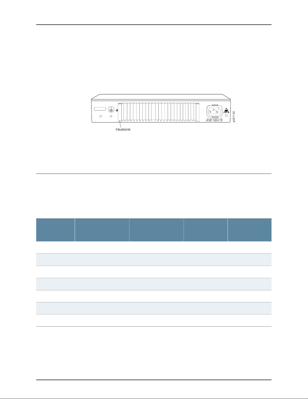
Figure 6: Rear Panel of an EX2200-C-12P Switch with Heatsink . . . . . . . . . . . . . . . 9
Chapter 2 Chassis Components and Descriptions . . . . . . . . . . . . . . . . . . . . . . . . . . . . . . . 13
Figure 7: Chassis Status LEDs in an EX2200 Switch Except the EX2200-C
Switch . . . . . . . . . . . . . . . . . . . . . . . . . . . . . . . . . . . . . . . . . . . . . . . . . . . . . . . . 14
Figure 8: Chassis Status LEDs in an EX2200-C Switch . . . . . . . . . . . . . . . . . . . . . . 14
Figure 9: LEDs on the Management Port on an EX2200 Switch Except the
EX2200-C Switch Model . . . . . . . . . . . . . . . . . . . . . . . . . . . . . . . . . . . . . . . . . . 15
Figure 10: LEDs on the Management Port on an EX2200-C Switch . . . . . . . . . . . . 15
Figure 11: LEDs on the Network Port . . . . . . . . . . . . . . . . . . . . . . . . . . . . . . . . . . . . . 16
Figure 12: LEDs on the Uplink Ports and Port Status Mode LEDs in an EX2200
Switch Except the EX2200-C Switch Model . . . . . . . . . . . . . . . . . . . . . . . . . . 16
Figure 13: Port Status Mode LEDs of the Dual-Purpose Uplink Ports of an
EX2200-C Switch . . . . . . . . . . . . . . . . . . . . . . . . . . . . . . . . . . . . . . . . . . . . . . . . 17
Chapter 3 Cooling System and Airflow . . . . . . . . . . . . . . . . . . . . . . . . . . . . . . . . . . . . . . . . 19
Figure 14: Airflow Through Non-PoE Models of EX2200 Switches Except the
EX2200-C Switch Model . . . . . . . . . . . . . . . . . . . . . . . . . . . . . . . . . . . . . . . . . 20
Figure15: AirflowThrough PoE Models of EX2200 SwitchesExceptthe EX2200-C
Switch Models . . . . . . . . . . . . . . . . . . . . . . . . . . . . . . . . . . . . . . . . . . . . . . . . . . 21
Part 2 Site Planning, Preparation, and Specifications
Chapter 6 Preparation Overview . . . . . . . . . . . . . . . . . . . . . . . . . . . . . . . . . . . . . . . . . . . . . . 47
Figure 16: Clearance Requirements for Airflow and Hardware Maintenance for
EX2200 Switches Except EX2200-C Switch Models . . . . . . . . . . . . . . . . . . . 57
Figure 17: Clearance Requirements for Airflow and Hardware Maintenance for
EX2200-C Switch Models . . . . . . . . . . . . . . . . . . . . . . . . . . . . . . . . . . . . . . . . 58
Figure 18: Airflow Through PoE Models of EX2200 Switches Except EX2200-C
Switch Models . . . . . . . . . . . . . . . . . . . . . . . . . . . . . . . . . . . . . . . . . . . . . . . . . 58
Figure 19: Airflow Through Non-PoE Models of EX2200 Switches Except
EX2200-C Switch Models . . . . . . . . . . . . . . . . . . . . . . . . . . . . . . . . . . . . . . . . 59
ixCopyright © 2017, Juniper Networks, Inc.

EX2200 and EX2200-C Switches Hardware Guide
Chapter 7 Power Specifications and Requirements . . . . . . . . . . . . . . . . . . . . . . . . . . . . . 61
Figure 20: AC Plug Types . . . . . . . . . . . . . . . . . . . . . . . . . . . . . . . . . . . . . . . . . . . . . 63
Part 3 Initial Installation and Configuration
Chapter 11 Installing the Switch . . . . . . . . . . . . . . . . . . . . . . . . . . . . . . . . . . . . . . . . . . . . . . 89
Figure 21: Attaching Rubber Feet to a Switch Chassis . . . . . . . . . . . . . . . . . . . . . . 93
Figure 22: Attaching a Cable Guard to an EX2200-C Switch . . . . . . . . . . . . . . . . . 93
Figure 23: Securing the EX2200-C Switch Using Security Slots . . . . . . . . . . . . . . 94
Figure 24: Attaching the Mounting Bracket Along the Front of the Switch . . . . . . 96
Figure 25: Mounting the Switch on Two Posts of a Rack . . . . . . . . . . . . . . . . . . . . 96
Figure 26: Attaching the Front-Mounting Bracket to the Side Mounting-Rail . . . . 98
Figure 27: Attaching the Side Mounting-Rail to the Switch Chassis . . . . . . . . . . . 99
Figure 28: Mounting the Switch to the Front Posts of a Rack . . . . . . . . . . . . . . . . 99
Figure 29: Sliding the Rear Mounting-Blades into the Side Mounting-Rail . . . . . 100
Figure 30: Attaching Wall-Mount Brackets to a Switch Chassis . . . . . . . . . . . . . . 102
Figure 31: Measurements for Installing Mounting Screws . . . . . . . . . . . . . . . . . . . 103
Figure 32: Mounting the Switch on a Wall . . . . . . . . . . . . . . . . . . . . . . . . . . . . . . . 104
Figure 33: Measurements for Installing Mounting Screws for the EX2200-C
Switch . . . . . . . . . . . . . . . . . . . . . . . . . . . . . . . . . . . . . . . . . . . . . . . . . . . . . . . 105
Figure 34: Mounting the EX2200-C Switch on a Wall Using Screws . . . . . . . . . . 106
Figure 35: Attaching a Cable Guard to an EX2200-C Switch . . . . . . . . . . . . . . . . 106
Figure 36: Securing the EX2200-C Switch Using Security Slots . . . . . . . . . . . . . . 107
Figure 37: Measurements for Installing Mounting Screws for EX2200-C
Switch . . . . . . . . . . . . . . . . . . . . . . . . . . . . . . . . . . . . . . . . . . . . . . . . . . . . . . . 108
Figure 38: Mounting the EX2200-C Switch On or Under a Desk Using Screws . . 109
Figure 39: Attaching a Cable Guard to an EX2200-C Switch . . . . . . . . . . . . . . . . 110
Figure 40: Securing the EX2200-C Switch Using Security Slots . . . . . . . . . . . . . . 110
Figure 41: Mounting an EX2200-C Switch Using Magnet Mount . . . . . . . . . . . . . . 112
Figure 42: Attaching a Cable Guard to an EX2200-C Switch . . . . . . . . . . . . . . . . . 113
Figure 43: Securing the EX2200-C Switch Using Security Slots . . . . . . . . . . . . . . 113
Chapter 12 Connecting the Switch to Power . . . . . . . . . . . . . . . . . . . . . . . . . . . . . . . . . . . . 115
Figure 44: Connecting the Grounding Lug to a Switch Mounted on Four Posts of
a Rack . . . . . . . . . . . . . . . . . . . . . . . . . . . . . . . . . . . . . . . . . . . . . . . . . . . . . . . . 119
Figure 45: Connecting a Grounding Cable to an EX Series Switch . . . . . . . . . . . . 120
Figure 46: Connecting an AC Power Cord Retainer Clip to the AC Power Cord
Inlet on an EX2200 Switch . . . . . . . . . . . . . . . . . . . . . . . . . . . . . . . . . . . . . . . 122
Figure 47: Connecting an AC Power Cord to the AC Power Cord Inlet on an
EX2200 Switch . . . . . . . . . . . . . . . . . . . . . . . . . . . . . . . . . . . . . . . . . . . . . . . . 123
Figure 48: Securing Ring Lugs to the Terminals on the DC Power Supply . . . . . . 125
Chapter 13 Connecting the Switch to the Network . . . . . . . . . . . . . . . . . . . . . . . . . . . . . . 127
Figure 49: RJ-45 Connector on an Ethernet Cable . . . . . . . . . . . . . . . . . . . . . . . . . 127
Figure 50: Connecting a Device to a Network for Out-of-Band Management . . . 128
Figure 51: RJ-45 Connector on an Ethernet Cable . . . . . . . . . . . . . . . . . . . . . . . . . 128
Figure 52: Connecting a Device to a Management Console Through a Console
Server . . . . . . . . . . . . . . . . . . . . . . . . . . . . . . . . . . . . . . . . . . . . . . . . . . . . . . . . 129
Figure 53: Connecting a Device Directly to a Management Console . . . . . . . . . . . 129
Copyright © 2017, Juniper Networks, Inc.x

List of Figures
Figure 54: Connecting a Fiber-Optic Cable to an Optical Transceiver Installed in
a Device . . . . . . . . . . . . . . . . . . . . . . . . . . . . . . . . . . . . . . . . . . . . . . . . . . . . . . . 131
Chapter 14 Performing Initial Configuration . . . . . . . . . . . . . . . . . . . . . . . . . . . . . . . . . . . . 133
Figure 55: LCD Panel in an EX3200, EX4200, EX4500, EX4550, or EX8200
Switch . . . . . . . . . . . . . . . . . . . . . . . . . . . . . . . . . . . . . . . . . . . . . . . . . . . . . . . . 141
Figure 56: LCD Panel in an EX4300 Switch . . . . . . . . . . . . . . . . . . . . . . . . . . . . . . 141
Part 4 Installing, Maintaining, and Replacing Components
Chapter 15 Replacing Transceiver . . . . . . . . . . . . . . . . . . . . . . . . . . . . . . . . . . . . . . . . . . . . . 147
Figure 57: Installing a Transceiver . . . . . . . . . . . . . . . . . . . . . . . . . . . . . . . . . . . . . 149
Figure 58: Removing an SFP, SFP+, XFP, or a QSFP+ Transceiver . . . . . . . . . . . . 151
Chapter 16 Maintaining and Replacing Fiber-Optic Cable . . . . . . . . . . . . . . . . . . . . . . . . 153
Figure 59: Connecting a Fiber-Optic Cable to an Optical Transceiver Installed in
a Device . . . . . . . . . . . . . . . . . . . . . . . . . . . . . . . . . . . . . . . . . . . . . . . . . . . . . . 154
Chapter 17 Contacting Customer Support and Returning the Chassis or
Components . . . . . . . . . . . . . . . . . . . . . . . . . . . . . . . . . . . . . . . . . . . . . . . . . . . . . 157
Figure 60: Location of the Serial Number ID Label on EX2200 Switches . . . . . . 159
Part 6 Safety and Compliance Information
Chapter 24 Electrical Safety Guidelines and Warnings . . . . . . . . . . . . . . . . . . . . . . . . . . 209
Figure 61: Placing a Component into an Antistatic Bag . . . . . . . . . . . . . . . . . . . . . 212
xiCopyright © 2017, Juniper Networks, Inc.

EX2200 and EX2200-C Switches Hardware Guide
Copyright © 2017, Juniper Networks, Inc.xii

List of Tables
About the Documentation . . . . . . . . . . . . . . . . . . . . . . . . . . . . . . . . . . . . . . . . . . xv
Table 1: Notice Icons . . . . . . . . . . . . . . . . . . . . . . . . . . . . . . . . . . . . . . . . . . . . . . . . . xvi
Table 2: Text and Syntax Conventions . . . . . . . . . . . . . . . . . . . . . . . . . . . . . . . . . . xvi
Part 1 Overview
Chapter 1 System Overview . . . . . . . . . . . . . . . . . . . . . . . . . . . . . . . . . . . . . . . . . . . . . . . . . . . 3
Table 3: EX2200 Switch Models . . . . . . . . . . . . . . . . . . . . . . . . . . . . . . . . . . . . . . . . 9
Table 4: CLI Equivalents of Terms Used in Documentation for EX2200
Chapter 2 Chassis Components and Descriptions . . . . . . . . . . . . . . . . . . . . . . . . . . . . . . . 13
Table 5: Physical Specifications of the EX2200 Switch Chassis . . . . . . . . . . . . . . . 13
Table 6: Chassis Status LEDs in an EX2200 Switch . . . . . . . . . . . . . . . . . . . . . . . . 14
Table 7: Link/Activity LED on the Management Port on EX2200 Switches . . . . . . 15
Table 8: Status LED on the Management Port on EX2200 Switches . . . . . . . . . . . 16
Table 9: Link/Activity LED on the Network Ports and Uplink Ports in EX2200
Table 10: Status LED on the Network Ports, Uplink Ports, and Dual-Purpose
Chapter 4 Power Supplies . . . . . . . . . . . . . . . . . . . . . . . . . . . . . . . . . . . . . . . . . . . . . . . . . . . 23
Table 11: Power Consumed by EX2200 Switches . . . . . . . . . . . . . . . . . . . . . . . . . . 23
Chapter 5 Viewing System Information . . . . . . . . . . . . . . . . . . . . . . . . . . . . . . . . . . . . . . . . 25
Table 12: Details of a Virtual Chassis Member Switch . . . . . . . . . . . . . . . . . . . . . . 26
Table 13: Status of a Member Switch in a Virtual Chassis . . . . . . . . . . . . . . . . . . . . 27
Table 14: System Information . . . . . . . . . . . . . . . . . . . . . . . . . . . . . . . . . . . . . . . . . . 27
Table 15: Health Status . . . . . . . . . . . . . . . . . . . . . . . . . . . . . . . . . . . . . . . . . . . . . . 29
Table 16: Capacity Utilization . . . . . . . . . . . . . . . . . . . . . . . . . . . . . . . . . . . . . . . . . . 31
Table 17: Chassis Viewer for EX2200 Switches . . . . . . . . . . . . . . . . . . . . . . . . . . . . 32
Table 18: Chassis Viewer for EX2200-C Switches . . . . . . . . . . . . . . . . . . . . . . . . . . 33
Table 19: Chassis Viewer for EX3200, EX3300, and EX4200 Switches . . . . . . . . . 33
Table 20: Chassis Viewer for EX4300 Switches . . . . . . . . . . . . . . . . . . . . . . . . . . . 35
Table 21: Chassis Viewer for EX4500 Switches . . . . . . . . . . . . . . . . . . . . . . . . . . . 36
Table 22: Chassis Viewer for EX4550 Switches . . . . . . . . . . . . . . . . . . . . . . . . . . . 37
Table 23: Chassis Viewer for EX4600 Switches . . . . . . . . . . . . . . . . . . . . . . . . . . . 39
Table 24: Chassis Viewer for EX6210 Switches . . . . . . . . . . . . . . . . . . . . . . . . . . . . 39
Table 25: Chassis Viewer for EX8208 Switches . . . . . . . . . . . . . . . . . . . . . . . . . . . 40
Table 26: Chassis Viewer for EX8216 Switches . . . . . . . . . . . . . . . . . . . . . . . . . . . . 42
Table 27: Chassis Viewer for XRE200 External Routing Engines . . . . . . . . . . . . . . 42
Switches . . . . . . . . . . . . . . . . . . . . . . . . . . . . . . . . . . . . . . . . . . . . . . . . . . . . . . 10
Switches . . . . . . . . . . . . . . . . . . . . . . . . . . . . . . . . . . . . . . . . . . . . . . . . . . . . . . . 17
Uplink Ports in EX2200 Switches . . . . . . . . . . . . . . . . . . . . . . . . . . . . . . . . . . . 17
xiiiCopyright © 2017, Juniper Networks, Inc.

EX2200 and EX2200-C Switches Hardware Guide
Part 2 Site Planning, Preparation, and Specifications
Chapter 6 Preparation Overview . . . . . . . . . . . . . . . . . . . . . . . . . . . . . . . . . . . . . . . . . . . . . . 47
Table 28: Site Preparation Checklist . . . . . . . . . . . . . . . . . . . . . . . . . . . . . . . . . . . . 47
Table 29: EX Series Switch Environmental Tolerances . . . . . . . . . . . . . . . . . . . . . 49
Table 30: Site Electrical Wiring Guidelines . . . . . . . . . . . . . . . . . . . . . . . . . . . . . . . 53
Table 31: Physical Specifications of the EX2200 Switch Chassis . . . . . . . . . . . . . 54
Table 32: Rack Requirements and Specifications . . . . . . . . . . . . . . . . . . . . . . . . . . 55
Table 33: Cabinet Requirements and Specifications . . . . . . . . . . . . . . . . . . . . . . . 56
Chapter 7 Power Specifications and Requirements . . . . . . . . . . . . . . . . . . . . . . . . . . . . . 61
Table 34: AC Power Supply Electrical Specifications for EX2200 Switches . . . . . 61
Table 35: DC Power Supply Electrical Specifications for EX2200 Switches . . . . . 61
Table 36: AC Power Cord Specifications . . . . . . . . . . . . . . . . . . . . . . . . . . . . . . . . . 63
Table 37: Estimated Values for Factors Causing Link Loss . . . . . . . . . . . . . . . . . . 65
Chapter 8 Transceiver and Cable Specifications . . . . . . . . . . . . . . . . . . . . . . . . . . . . . . . . 67
Table 38: Specifications of Cables to Connect to Management Devices . . . . . . . 69
Chapter 9 Pinout Specifications . . . . . . . . . . . . . . . . . . . . . . . . . . . . . . . . . . . . . . . . . . . . . . 73
Table 39: Console Port Connector Pinout Information . . . . . . . . . . . . . . . . . . . . . . 73
Table 40: Mini-USB Type-B Console Port Pinout Information . . . . . . . . . . . . . . . . 74
Table 41: RJ-45 Management Port Connector Pinout Information . . . . . . . . . . . . . 76
Table 42: 10/100/1000BASE-T Ethernet Network Port Connector Pinout
Information . . . . . . . . . . . . . . . . . . . . . . . . . . . . . . . . . . . . . . . . . . . . . . . . . . . . 76
Table 43: SFP Network Port Connector Pinout Information . . . . . . . . . . . . . . . . . . 77
Table 44: SFP+ Network Port Connector Pinout Information . . . . . . . . . . . . . . . . 78
Table 45: QSFP+ Network Port Connector Pinout Information . . . . . . . . . . . . . . . 79
Table 46: RJ-45 to DB-9 Serial Port Adapter Pinout Information . . . . . . . . . . . . . . 81
Part 3 Initial Installation and Configuration
Chapter 10 Unpacking the Switch . . . . . . . . . . . . . . . . . . . . . . . . . . . . . . . . . . . . . . . . . . . . . 85
Table 47: Parts List for EX2200 Switches . . . . . . . . . . . . . . . . . . . . . . . . . . . . . . . . 86
Chapter 11 Installing the Switch . . . . . . . . . . . . . . . . . . . . . . . . . . . . . . . . . . . . . . . . . . . . . . 89
Table 48: EX2200 Switch Mounting Methods . . . . . . . . . . . . . . . . . . . . . . . . . . . . 90
Chapter 12 Connecting the Switch to Power . . . . . . . . . . . . . . . . . . . . . . . . . . . . . . . . . . . . 115
Table 49: Parts and Tools Required for Connecting an EX Series Switch to Earth
Ground . . . . . . . . . . . . . . . . . . . . . . . . . . . . . . . . . . . . . . . . . . . . . . . . . . . . . . . 116
Table 50: Special Instructions to Follow Before Connecting Earth Ground to a
Switch . . . . . . . . . . . . . . . . . . . . . . . . . . . . . . . . . . . . . . . . . . . . . . . . . . . . . . . . 118
Part 5 Troubleshooting
Chapter 18 Alarms and Syslog Messages . . . . . . . . . . . . . . . . . . . . . . . . . . . . . . . . . . . . . . 165
Table 51: Alarm Terms . . . . . . . . . . . . . . . . . . . . . . . . . . . . . . . . . . . . . . . . . . . . . . . 165
Table 52: Chassis Component Alarm Conditions on EX2200 Switches . . . . . . . . 167
Table 53: Summary of Key Alarm Output Fields . . . . . . . . . . . . . . . . . . . . . . . . . . 173
Table 54: Filtering System Log Messages . . . . . . . . . . . . . . . . . . . . . . . . . . . . . . . 174
Table 55: Viewing System Log Messages . . . . . . . . . . . . . . . . . . . . . . . . . . . . . . . . 176
Copyright © 2017, Juniper Networks, Inc.xiv

About the Documentation
•
Documentation and Release Notes on page xv
•
Supported Platforms on page xv
•
Documentation Conventions on page xv
•
Documentation Feedback on page xvii
•
Requesting Technical Support on page xviii
Documentation and Release Notes
To obtain the most current version of all Juniper Networks®technical documentation,
see the product documentation page on the Juniper Networks website at
http://www.juniper.net/techpubs/.
If the information in the latest release notes differs from the information in the
documentation, follow the product Release Notes.
Juniper Networks Books publishes books by Juniper Networks engineers and subject
matter experts. These books go beyond the technical documentation to explore the
nuances of network architecture, deployment, and administration. The current list can
be viewed at http://www.juniper.net/books.
Supported Platforms
For the features described in this document, the following platforms are supported:
•
EX2200
Documentation Conventions
Table 1 on page xvi defines notice icons used in this guide.
xvCopyright © 2017, Juniper Networks, Inc.
EX2200 and EX2200-C Switches Hardware Guide
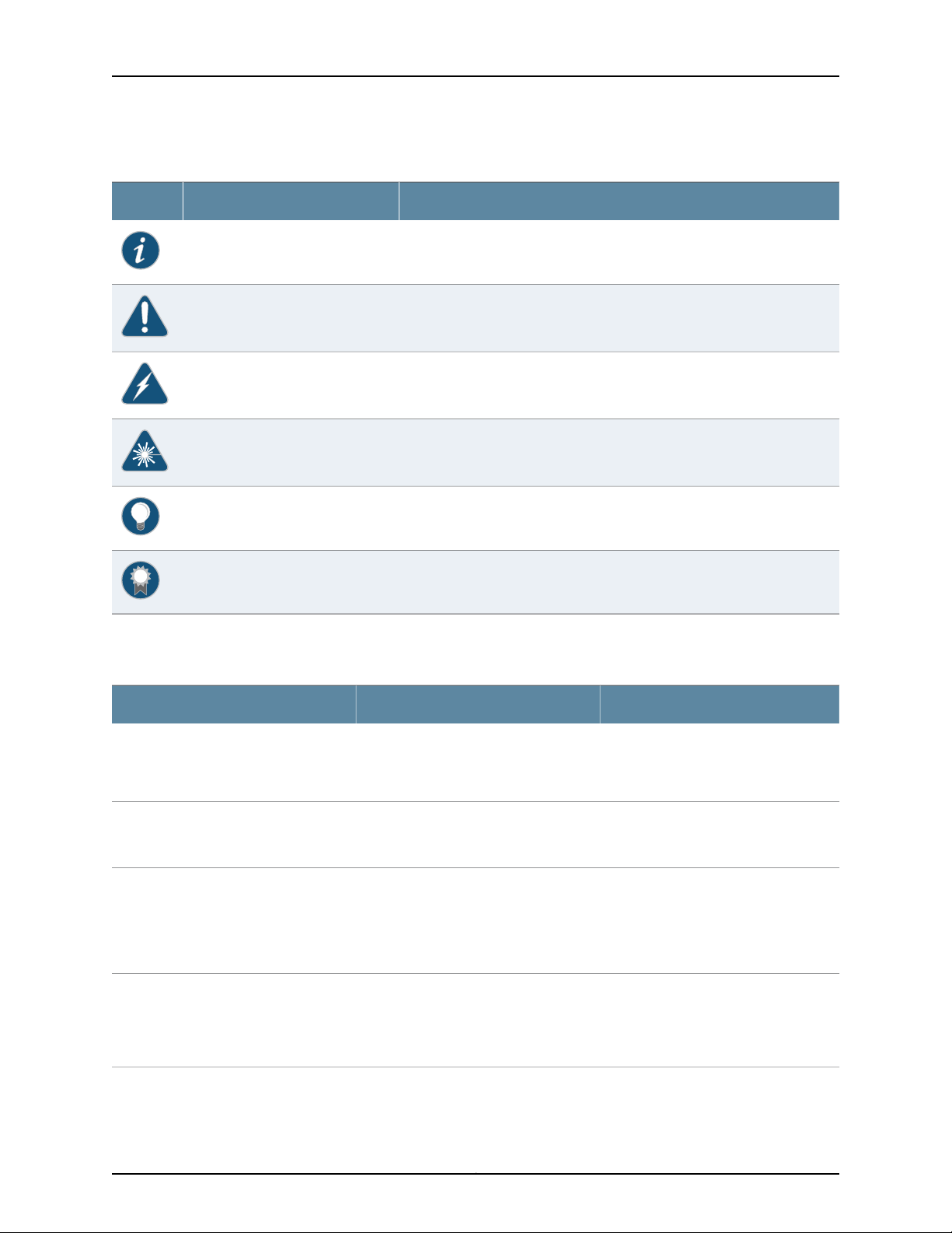
Table 1: Notice Icons
DescriptionMeaningIcon
Indicates important features or instructions.Informational note
Indicates a situation that might result in loss of data or hardware damage.Caution
Alerts you to the risk of personal injury or death.Warning
Alerts you to the risk of personal injury from a laser.Laser warning
Indicates helpful information.Tip
Table 2 on page xvi defines the text and syntax conventions used in this guide.
Table 2: Text and Syntax Conventions
Represents text that you type.Bold text like this
Fixed-width text like this
Italic text like this
Italic text like this
Represents output that appears on the
terminal screen.
•
Introduces or emphasizes important
new terms.
•
Identifies guide names.
•
Identifies RFC and Internet draft titles.
Represents variables (options for which
you substitute a value) in commands or
configuration statements.
Alerts you to a recommended use or implementation.Best practice
ExamplesDescriptionConvention
To enter configuration mode, type the
configure command:
user@host> configure
user@host> show chassis alarms
No alarms currently active
•
A policy term is a named structure
that defines match conditions and
actions.
•
Junos OS CLI User Guide
•
RFC 1997,BGP Communities Attribute
Configure the machine’s domain name:
[edit]
root@# set system domain-name
domain-name
Copyright © 2017, Juniper Networks, Inc.xvi

Table 2: Text and Syntax Conventions (continued)
Text like this
Represents names of configuration
statements, commands, files, and
directories;configurationhierarchy levels;
or labels on routing platform
components.
About the Documentation
ExamplesDescriptionConvention
•
To configure a stub area, include the
stub statement at the [edit protocols
ospf area area-id] hierarchy level.
•
The console port is labeled CONSOLE.
stub <default-metric metric>;Encloses optional keywords or variables.< > (angle brackets)
| (pipe symbol)
# (pound sign)
[ ] (square brackets)
Indention and braces ( { } )
; (semicolon)
GUI Conventions
Bold text like this
Indicatesa choice between the mutually
exclusivekeywordsor variables on either
side of the symbol. The set of choices is
often enclosed in parentheses for clarity.
same line as the configurationstatement
to which it applies.
Encloses a variable for which you can
substitute one or more values.
Identifies a level in the configuration
hierarchy.
Identifies a leaf statement at a
configuration hierarchy level.
Representsgraphicaluser interface(GUI)
items you click or select.
broadcast | multicast
(string1 | string2 | string3)
rsvp { # Required for dynamic MPLS onlyIndicates a comment specified on the
community name members [
community-ids ]
[edit]
routing-options {
static {
route default {
nexthop address;
retain;
}
}
}
•
In the Logical Interfaces box, select
All Interfaces.
•
To cancel the configuration, click
Cancel.
> (bold right angle bracket)
Documentation Feedback
We encourage you to provide feedback, comments, and suggestions so that we can
improve the documentation. You can provide feedback by using either of the following
methods:
•
Online feedback rating system—On any page of the Juniper Networks TechLibrary site
at http://www.juniper.net/techpubs/index.html,simply click the stars to ratethe content,
and use the pop-up form to provide us with information about your experience.
Alternately, you can use the online feedback form at
http://www.juniper.net/techpubs/feedback/.
Separates levels in a hierarchy of menu
selections.
In the configuration editor hierarchy,
select Protocols>Ospf.
xviiCopyright © 2017, Juniper Networks, Inc.

EX2200 and EX2200-C Switches Hardware Guide
•
E-mail—Sendyourcomments to techpubs-comments@juniper.net.Include the document
or topic name, URL or page number, and software version (if applicable).
Requesting Technical Support
Technicalproduct support is availablethrough the Juniper NetworksTechnicalAssistance
Center (JTAC). If you are a customer with an active J-Care or Partner Support Service
support contract, or are covered under warranty, and need post-sales technical support,
you can access our tools and resources online or open a case with JTAC.
•
JTAC policies—For a complete understanding of our JTAC procedures and policies,
review the JTAC User Guide located at
http://www.juniper.net/us/en/local/pdf/resource-guides/7100059-en.pdf.
•
Product warranties—For product warranty information, visit
http://www.juniper.net/support/warranty/.
•
JTAC hours of operation—The JTAC centers have resources available 24 hours a day,
7 days a week, 365 days a year.
Self-Help Online Tools and Resources
For quick and easy problem resolution, Juniper Networks has designed an online
self-service portal called the Customer Support Center (CSC) that provides you with the
following features:
•
Find CSC offerings: http://www.juniper.net/customers/support/
•
Search for known bugs: http://www2.juniper.net/kb/
•
Find product documentation: http://www.juniper.net/techpubs/
•
Find solutions and answer questions using our Knowledge Base: http://kb.juniper.net/
•
Download the latest versions of software and review release notes:
http://www.juniper.net/customers/csc/software/
•
Search technical bulletins for relevant hardware and software notifications:
http://kb.juniper.net/InfoCenter/
•
Join and participate in the Juniper Networks Community Forum:
http://www.juniper.net/company/communities/
•
Open a case online in the CSC Case Management tool: http://www.juniper.net/cm/
To verify service entitlementby product serial number, use our Serial Number Entitlement
(SNE) Tool: https://tools.juniper.net/SerialNumberEntitlementSearch/
Opening a Case with JTAC
You can open a case with JTAC on the Web or by telephone.
•
Use the Case Management tool in the CSC at http://www.juniper.net/cm/.
•
Call 1-888-314-JTAC (1-888-314-5822 toll-free in the USA, Canada, and Mexico).
Copyright © 2017, Juniper Networks, Inc.xviii

About the Documentation
For international or direct-dial options in countries without toll-free numbers, see
http://www.juniper.net/support/requesting-support.html.
xixCopyright © 2017, Juniper Networks, Inc.

EX2200 and EX2200-C Switches Hardware Guide
Copyright © 2017, Juniper Networks, Inc.xx

PART 1
Overview
•
System Overview on page 3
•
Chassis Components and Descriptions on page 13
•
Cooling System and Airflow on page 19
•
Power Supplies on page 23
•
Viewing System Information on page 25
1Copyright © 2017, Juniper Networks, Inc.

EX2200 and EX2200-C Switches Hardware Guide
Copyright © 2017, Juniper Networks, Inc.2

CHAPTER 1
System Overview
•
EX2200 Switches Hardware Overview on page 3
•
EX2200 Switch Models on page 9
•
EX2200 Switch Hardware and CLI Terminology Mapping on page 10
EX2200 Switches Hardware Overview
Juniper Networks EX Series Ethernet Switches provide scalable connectivity for the
enterprise market, including branch offices, campus locations, and data centers. The
switches run the Juniper Networks Junos operating system (Junos OS), which provides
Layer 2 and Layer 3 switching, routing, and security services. The same Junos OS code
base that runs on EX Series switches also runs on all Juniper Networks M Series, MX
Series, and T Series routers and SRX Series Services Gateways.
Juniper Networks EX2200 Ethernet Switches provide connectivity for low-density
environments.
This topic describes:
•
EX2200 Switches First View on page 3
•
Uplink Ports on page 4
•
Console Port on page 4
•
Cable Guard on page 5
•
Security Slots on page 5
•
Power over Ethernet (PoE) Ports on page 5
•
Front Panel of an EX2200 Switch on page 6
•
Rear Panel of an EX2200 Switch on page 8
EX2200 Switches First View
EX2200 switches are available in models with 12 , 24, or 48 built-in network ports. The
compact, fanless model, EX2200-C switches have 12 network ports.
3Copyright © 2017, Juniper Networks, Inc.

EX2200 and EX2200-C Switches Hardware Guide
EX2200 switches provide:
•
Up to four uplink ports
•
12 (compact, fanless model), 24, or 48 built-in networkports with 10/100/1000BASE-T
Gigabit Ethernet connectors
•
Virtual Chassis capability—Starting with Junos OS Release 12.2, you can connect up to
four EX2200 switches (including EX2200-C switches) together to form one unit that
you manage as a single chassis, called a Virtual Chassis. For information about
understanding and configuring Virtual Chassis, see Virtual Chassis Feature Guide for
EX2200, EX3300, EX4200, EX4500 and EX4550 Switches.
•
Power over Ethernet (PoE or PoE+) on all network ports (in PoE-capable models)
Uplink Ports
Each EX2200 switch except the EX2200-C switch model has four uplink ports that
support 1-gigabit small form-factor pluggable (SFP) transceivers for use with fiber
connections and copper connections.
Console Port
Each EX2200-C switch has two dual-purpose uplink ports. Each dual uplink port consists
of an RJ-45 port (in which you can connect a copper Ethernet cable) and an SFP port
(into which you can plug a transceiver). Only one of the ports can be active at a time. By
default, if you connect a copper Ethernet cable to the RJ-45 port, this port becomes the
active port provided that there is no connection made on the other port. If you plug a
transceiver into the SFP port, this port becomes the active port whether or not a copper
Ethernet cable is connected to the other port. You can change this default behavior by
explicitly configuring a media type—copper or fiber—for the dual-purpose port by using
the media-type command. For more information, see Configuring the Media Type on
Dual-Purpose Uplink Ports (CLI Procedure).
You can use an SFP uplink port connection between EX2200 switches to interconnect
the switches into an EX2200 Virtual Chassis. For this, you must explicitly configure an
SFP port each on the switches to be connected as a VCP. See Setting an Uplink Port on
an EX Series Switch as a Virtual Chassis Port (CLI Procedure).
For information about the supported optical and copper interfaces, see “Pluggable
Transceivers Supported on EX2200 Switches” on page 67.
Each EX2200 switch exceptthe EX2200-C switch model has an RJ-45console port that
accepts a cable with RJ-45 connector.
The EX2200-C switch has two console ports: an RJ-45 port and a Mini-USB Type-B port.
The RJ-45 console port accepts a cable with an RJ-45 connector and the Mini-USB
Type-B console port accepts a Mini-B plug (5-pin) connector to connect to the console
management device. The switch activates only one console port at a time, either the
RJ-45 console port or the Mini USB type-B console port. By default, the RJ-45 port is the
active console port and the Mini-USB Type-B port is the passive console port. You can
change the default setting of a console port by using the port-type command. See
Configuring the Console Port Type (CLI Procedure).
Copyright © 2017, Juniper Networks, Inc.4

Cable Guard
On an EX2200-C switch model, you can install a cable guard to secure the cables
connected to the switch. The cable guard has slots in the front of it through which you
can pass all the cables to prevent them from being accidently unplugged or removed
after they are connected. See “Mounting an EX2200 Switch on a Desk or Other Level
Surface” on page 92.
Security Slots
Each EX2200-C switch model has security slots on the left and right panels of the chassis.
Use the security slots tolock and secure the chassis in the installationsite with a standard
cable lock . See “Mounting an EX2200 Switch on a Desk or Other Level Surface” on
page 92.
Power over Ethernet (PoE) Ports
EX2200 switches are available in models with or without PoE/PoE+ capability. Models
that support PoE/PoE+ provide that support on all network ports. PoE ports provide
electrical current to devices—such as IP phones, wireless access points, and security
cameras—through network cables, thus eliminating the need for separate power cords
for those devices.
Chapter 1: System Overview
EX2200 switches with DC power supply do not provide PoE.
NOTE: Starting with Junos OS Release 12.2R1, PoE commands are enabled
on all non-PoE-capable EX2200 switch models. The PoE commands do not
provide any meaningful information on standalone non-PoE-capable switch
models. However, in an EX2200 Virtual Chassis, you can execute PoE
commands from a non-PoE-capable switch that is the master, to configure
PoE on PoE-capable Virtual Chassis members.
PoE-capable EX2200 switches running Junos OS Release 10.3 or later support powered
devices that comply with IEEE 802.3af (PoE) and IEEE 802.3at (PoE+).
NOTE: IEEE 802.3at class 4 powered devices require category 5 or higher
Ethernet cables.
EX2200 switches running Junos OS Release 10.2 or earlier support powered devices that
comply with IEEE 802.3af (PoE).
The remainder of this topicuses the term PoE to refer to both PoE and PoE+ unless there
is a need to distinguish between the two.
5Copyright © 2017, Juniper Networks, Inc.
EX2200 and EX2200-C Switches Hardware Guide
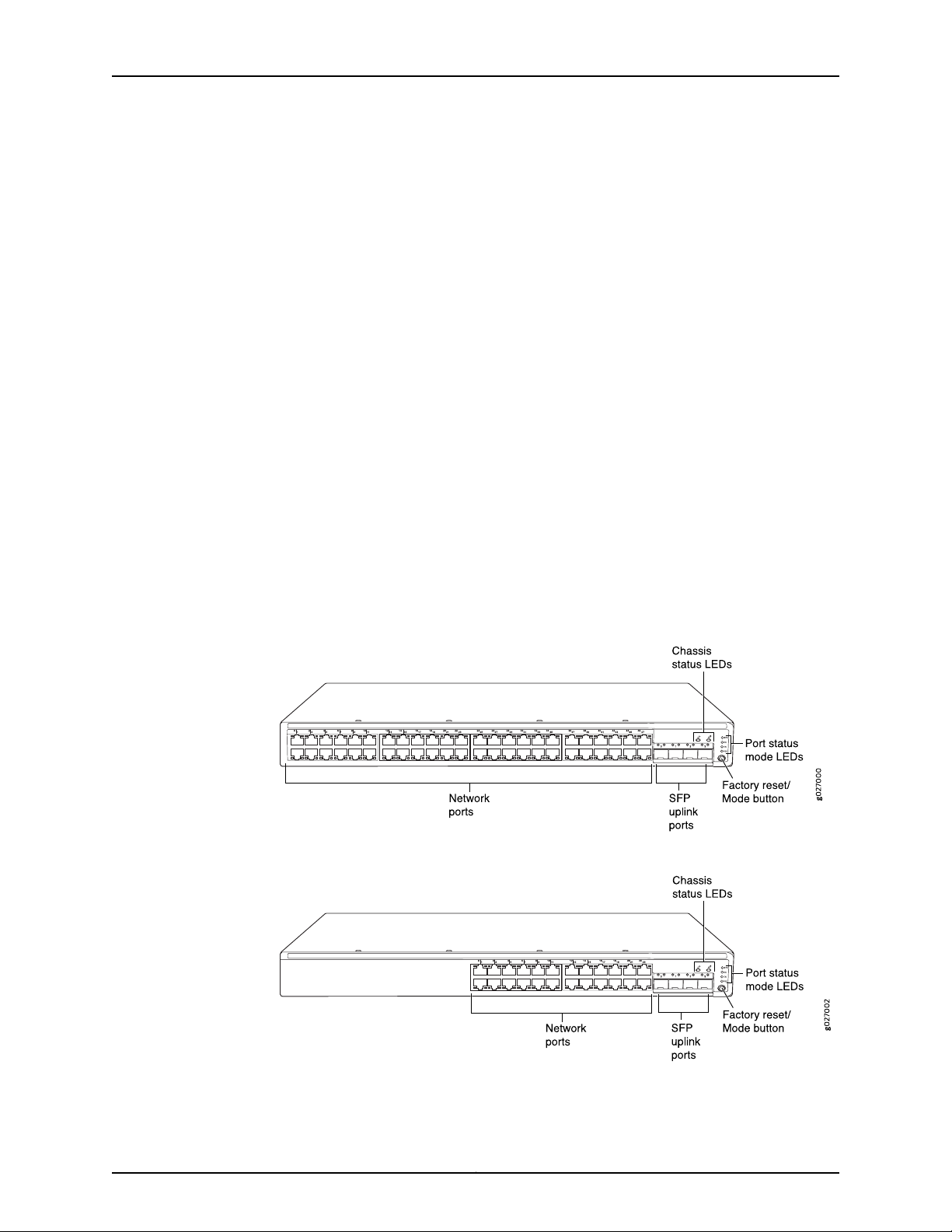
Front Panel of an EX2200 Switch
The front panel of an EX2200 switch except the EX2200-C switch models consists of
the following components:
•
Network ports—depending on the switch model, either of:
•
24 or 48 10/100/1000BASE-T Gigabit Ethernet ports, with Power over Ethernet
(PoE) not available in EX2200-24T, EX2200-24T-DC, and EX2200-48T models
•
24 or 48 10/100/1000BASE-T Gigabit Ethernet ports, with Power over Ethernet
(PoE) available in EX2200-24P and EX2200-48P models
•
4 built-in SFP uplink ports. You can use these ports to forward network traffic or
configure them into Virtual Chassis ports (VCPs) to interconnect EX2200 switches
into a Virtual Chassis.
•
2 chassis status LEDs
•
4 port status mode LEDs
•
Factory reset/Mode button
Figure 1 on page 6 shows the front panel of an EX2200 switch with 48 Gigabit Ethernet
ports. Figure 2 on page 6 shows the front panel of an EX2200 switch with 24 Gigabit
Ethernet ports.
Figure 1: Front Panel of an EX2200 Switch with 48 Gigabit Ethernet Ports
Figure 2: Front Panel of an EX2200 Switch with 24 Gigabit Ethernet Ports
Copyright © 2017, Juniper Networks, Inc.6
Chapter 1: System Overview
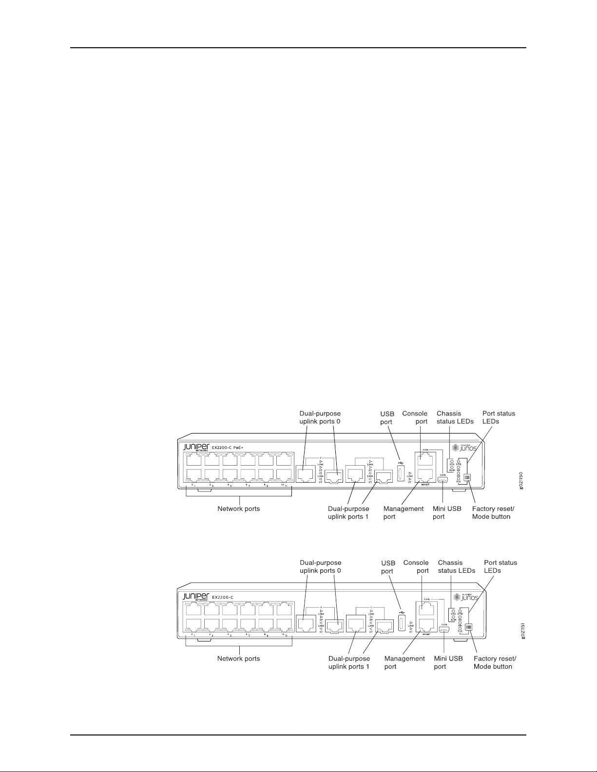
The front panel of an EX2200-C switch consists of the following components:
•
Network ports—depending on the switch model, either of:
•
12 10/100/1000BASE-T Ethernet ports, (PoE+) in EX2200-C-12P
•
12 10/100/1000BASE-T Ethernet ports, (non-PoE) in EX2200-C-12T
•
2 built-in dual-purpose uplink ports, each of which includes one 10/100/1000 RJ-45
Ethernet port and one SFP port
•
1 USB port
•
1 Mini-USB console port
•
1 RJ-45 console port
•
1 Management Ethernet port
•
2 chassis status LEDs
•
4 port status mode LEDs in PoE+ and 3 port status mode LEDs in non-PoE
•
Factory reset/Mode button
Figure 3 on page 7 shows the front panel of an EX2200-C switch with 12 Gigabit Ethernet
PoE+ ports and Figure 4 on page 7 shows the front panel of an EX2200-C switch with
12 Gigabit Ethernet non-PoE ports.
Figure 3: Front Panel of an EX2200-C Switch with 12 Gigabit Ethernet
Ports (PoE+)
Figure 4: Front Panel of an EX2200-C Switch with 12 Gigabit Ethernet
Ports (non-PoE)
7Copyright © 2017, Juniper Networks, Inc.
g027001
USB
port
Management
Ethernet por t
Console RPS
port
port
Protective
earthing terminal
Air exhaust without fan
(closed on non-PoE models)
Air exhaust
with fan
AC power
cord inlet
ESD
point
EX2200-24-4G REV: X1
750-026464 REV: X3
MAC:00:23:9C:oE:19:00
Mfg.Date
20090227
MADEIN CHINA
Serial number
ID label
Air intake with fan for power supply
(fan on PoE models only)
EX2200 and EX2200-C Switches Hardware Guide
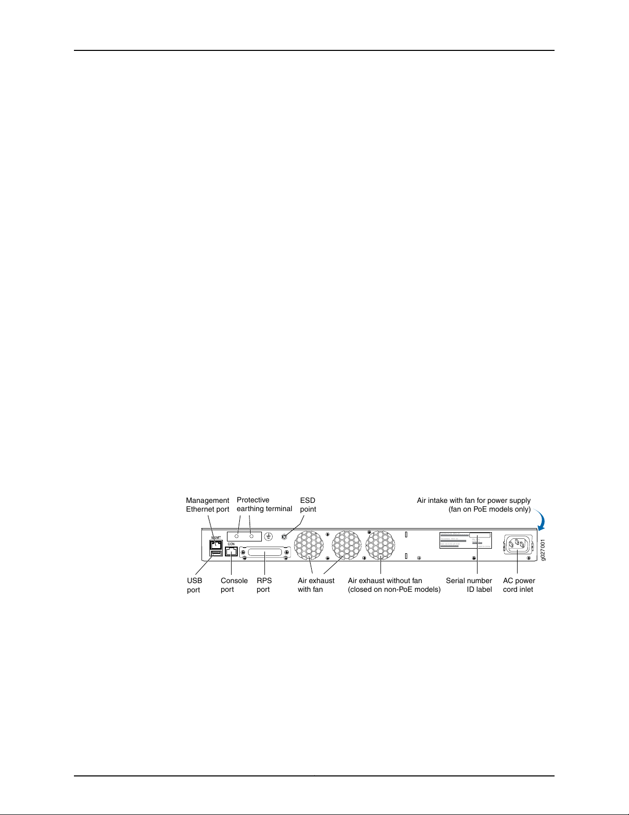
Rear Panel of an EX2200 Switch
The rear panel of the EX2200 switch except the EX2200-C switch models consists of
the following components:
•
Management Ethernet port
•
USB port
•
Console port
•
Protective earthing terminal
•
Redundant power system (RPS) port
•
ESD point
•
Air exhaust
•
Serial number ID label
•
AC power cord inlet or DC power terminals
Figure 5 on page 8 shows the rear panel of an EX2200 switch with an AC power supply.
All EX2200 switches except the EX2200-C switch model have three exhaust openings
on the rear panel. The two exhaust openings on the left have fans behind them and are
open. The exhaust opening on the right has no fan within it. This opening is exposed on
Power over Ethernet (PoE) models and sealed on non-PoE models. On PoE models, this
opening exhausts the air from the fan at the air intake for the power supply on the side
panel.
The power cord retainer clips extend out of the chassis by 3 in.
Figure 5: Rear Panel of an EX2200 Switch with AC Power Supply
The rear panel of an EX2200-C switch consists of the following components:
•
Protective earthing terminal
•
ESD point
•
Serial number ID label
•
AC power cord inlet
•
Heatsink—only in PoE+ models
Copyright © 2017, Juniper Networks, Inc.8
g021152
Heatsink
Chapter 1: System Overview
Figure 6 on page 9 shows the rear panel of an EX2200-C-12P switch with heatsink.
EX2200-C switches being fanless models have no exhaust openings. The switch has
vents on the top and on both the sides of the chassis. The PoE+ models have a heatsink
installed in the rear panel to dissipate the heat, while non-PoE models have no heatsink.
Figure 6: Rear Panel of an EX2200-C-12P Switch with Heatsink
Related
Documentation
EX2200 Switch Models on page 9•
• Site Preparation Checklist for EX2200 Switches on page 47
EX2200 Switch Models
The EX2200 switch is available with 12, 24, or 48 built-in network ports with full Power
over Ethernet (PoE)capability (all 12, 24, or 48 built-in network ports support PoE) or no
PoE capability. EX2200 switches with DC power supply do not provide PoE.
Table 3 on page 9 lists the EX2200 switch models.
Table 3: EX2200 Switch Models
Ports in Which PoE is
AvailableAccess PortsModel
Maximum System
PowerAvailablefor
PoE
First Junos OS
Release
11.3R1––12 Gigabit EthernetEX2200-C-12T-2G
11.3R1100 WAll 12 ports12 Gigabit EthernetEX2200-C-12P-2G
10.1R1––24 Gigabit EthernetEX2200-24T-4G
10.1R1405 WAll 24 ports24 Gigabit EthernetEX2200-24P-4G
Related
Documentation
10.1R1––24 Gigabit EthernetEX2200-24T-4G-DC
10.1R1––48 Gigabit EthernetEX2200-48T-4G
10.1R1405 WAll 48 ports48 Gigabit EthernetEX2200-48P-4G
EX2200 Switches Hardware Overview on page 3•
9Copyright © 2017, Juniper Networks, Inc.

EX2200 and EX2200-C Switches Hardware Guide
EX2200 Switch Hardware and CLI Terminology Mapping
This topic describes the hardware terms used in EX2200 switch documentation and the
corresponding terms used in the Junos OS command line interface (CLI). See
Table 4 on page 10.
Table 4: CLI Equivalents of Terms Used in Documentation for EX2200 Switches
Hardware Item (as
displayed in the CLI)
Chassis
FPC (n)
Description (as
displayed in the CLI)
•
EX2200-C-12T-2G
•
EX2200-C-12P-2G
•
EX2200-24T-4G
•
EX2200-24P-4G
•
EX2200-24T-4G-DC
•
EX2200-48T-4G
•
EX2200-48P-4G
the Flexible PIC
Concentrator (FPC)
One of the following:
•
EX2200-C-12T-2G
•
EX2200-C-12P-2G
•
EX2200-24T-4G
•
EX2200-24P-4G
•
EX2200-24T-4G-DC
•
EX2200-48T-4G
•
EX2200-48P-4G
Value (as displayed
in the CLI)
Value of n is always 0.Abbreviated name of
Item in
Documentation
Switch chassis–One of the following:
The switch does not
have actual FPCs. In
this case, FPC refers to
the switch itself.
Additional
Information
“Chassis Physical
Specifications for
EX2200 Switches” on
page 13
Understanding Interface
Naming Conventions on
EX Series Switches
PIC (n)
Abbreviated name of
the Physical Interface
Card (PIC)
•
12x 10/100/1000
BASE-T
•
24x 10/100/1000
BASE-T
•
48x 10/100/1000
BASE-T
n is a value in the range
of 0–1.
PIC 0One of the following:
The switch does not
have actual PIC
devices; see entries for
PIC 0 through PIC 1 for
the equivalent item on
the switch.
Built-in network ports
on the front panel of
the switch
Copyright © 2017, Juniper Networks, Inc.10
Understanding Interface
Naming Conventions on
EX Series Switches
“EX2200 Switches
Hardware Overview”
on page 3
 Loading...