

Page 1

EX4200 Switch Hardware Guide
Published
2020-12-15
Page 2

Juniper Networks, Inc.
1133 Innovation Way
Sunnyvale, California 94089
USA
408-745-2000
www.juniper.net
Juniper Networks, the Juniper Networks logo, Juniper, and Junos are registered trademarks of Juniper Networks, Inc. in
the United States and other countries. All other trademarks, service marks, registered marks, or registered service marks
are the property of their respective owners.
Juniper Networks assumes no responsibility for any inaccuracies in this document. Juniper Networks reserves the right
to change, modify, transfer, or otherwise revise this publication without notice.
EX4200 Switch Hardware Guide
Copyright © 2020 Juniper Networks, Inc. All rights reserved.
The information in this document is current as of the date on the title page.
ii
YEAR 2000 NOTICE
Juniper Networks hardware and software products are Year 2000 compliant. Junos OS has no known time-related
limitations through the year 2038. However, the NTP application is known to have some difficulty in the year 2036.
END USER LICENSE AGREEMENT
The Juniper Networks product that is the subject of this technical documentation consists of (or is intended for use with)
Juniper Networks software. Use of such software is subject to the terms and conditions of the End User License Agreement
(“EULA”) posted at https://support.juniper.net/support/eula/. By downloading, installing or using such software, you
agree to the terms and conditions of that EULA.
Page 3

Table of Contents
1
About the Documentation | xi
Documentation and Release Notes | xi
Using the Examples in This Manual | xi
Merging a Full Example | xii
Merging a Snippet | xiii
Documentation Conventions | xiii
Documentation Feedback | xvi
Requesting Technical Support | xvi
Self-Help Online Tools and Resources | xvii
Creating a Service Request with JTAC | xvii
iii
Overview
EX4200 System Overview | 19
EX4200 Switches Hardware Overview | 19
Benefits of the EX4200 Switch | 19
EX4200 Switches | 20
Uplink Modules | 21
Power over Ethernet Ports | 21
EX4200 Switch Models | 21
EX4200 Switch Hardware and CLI Terminology Mapping | 23
Chassis Physical Specifications for EX4200 Switches | 27
Field-Replaceable Units in EX4200 Switches | 28
EX4200 Chassis | 29
Front Panel of an EX4200 Switch | 29
Rear Panel of an EX4200 Switch | 30
LCD Panel in EX4200 Switches | 31
LCD Panel Modes | 32
Uplink Modules in EX4200 Switches | 33
SFP Uplink Module | 34
SFP+ Uplink Module and SFP+ MACsec Uplink Module | 35
Page 4

XFP Uplink Module | 37
2
Chassis Status LEDs in EX4200 Switches | 37
Management Port LEDs in EX4200 Switches | 39
Network Port LEDs in EX4200 Switches | 40
EX4200 Cooling System | 45
Fan Tray | 46
Airflow Direction in the EX4200 Switch Chassis | 46
EX4200 Power System | 47
Power Supply in EX4200 Switches | 47
AC Power Supplies | 48
DC Power Supplies | 49
PoE Power Budget and AC Power Supplies | 50
AC Power Supply LEDs in EX4200 Switches | 52
iv
DC Power Supply LEDs in EX4200 Switches | 52
Power Specifications for EX4200 Switches | 53
AC Power Cord Specifications for EX4200 Switches | 54
Site Planning, Preparation, and Specifications
Site Preparation Checklist for EX4200 Switches | 58
EX4200 Site Guidelines and Requirements | 59
Environmental Requirements and Specifications for EX Series Switches | 60
General Site Guidelines | 65
Site Electrical Wiring Guidelines | 65
Rack Requirements | 66
Cabinet Requirements | 67
Requirements for Mounting an EX4200 Switch on a Desktop or Wall | 68
Clearance Requirements for Airflow and Hardware Maintenance for EX4200 Switches | 69
EX4200 Network Cable and Transceiver Planning | 70
Pluggable Transceivers Supported on EX4200 Switches | 71
SFP+ Direct Attach Copper Cables for EX Series Switches | 72
Cable Specifications | 72
List of DAC Cables Supported on EX Series Switches | 73
Page 5

Standards Supported by These Cables | 73
3
Understanding EX Series Switches Fiber-Optic Cable Signal Loss, Attenuation, and
Dispersion | 74
Signal Loss in Multimode and Single-Mode Fiber-Optic Cable | 74
Attenuation and Dispersion in Fiber-Optic Cable | 74
Calculating the Fiber-Optic Cable Power Budget for EX Series Devices | 75
Calculating the Fiber-Optic Cable Power Margin for EX Series Devices | 76
EX4200 Management Cable Specifications and Pinouts | 78
Management Cable Specifications | 78
Console Port Connector Pinout Information | 79
USB Port Specifications for an EX Series Switch | 79
RJ-45 Management Port Connector Pinout Information | 80
RJ-45 Port, SFP Port, SFP+ Port, QSFP+ Port, and QSFP28 Port Connector Pinout
Information | 81
v
RJ-45 to DB-9 Serial Port Adapter Pinout Information | 85
Uplink Modules Connector Pinout Information for EX4200 Switches | 86
Virtual Chassis Ports Connector Pinout Information for EX4200 Switches | 95
EX4200 Virtual Chassis | 99
Understanding EX4200, EX4500, and EX4550 Virtual Chassis Hardware Configurations | 99
Ports Used to Interconnect Virtual Chassis Members | 100
Number of Switches, Required Software Releases, and Member Roles That You Configure
in the Virtual Chassis | 101
Virtual Chassis Module | 102
Switch Role and Member ID on the LCD Panel | 102
Planning EX4200, EX4500, and EX4550 Virtual Chassis | 103
Virtual Chassis Cabling Configuration Examples for EX4200 Switches | 105
Initial Installation and Configuration
Unpacking and Mounting the EX4200 Switch | 110
Unpacking an EX4200 Switch | 110
Parts Inventory (Packing List) for an EX4200 Switch | 111
Register Products—Mandatory to Validate SLAs | 114
Installing and Connecting an EX4200 Switch | 114
Mounting an EX4200 Switch | 115
Page 6

Mounting an EX4200 Switch on a Desk or Other Level Surface | 116
Mounting an EX4200 Switch on Two Posts in a Rack or Cabinet | 117
Mounting an EX4200 Switch on Four Posts in a Rack or Cabinet | 120
Mounting an EX4200 Switch in a Recessed Position in a Rack or Cabinet | 123
Mounting an EX4200 Switch on a Wall | 124
Connecting the EX4200 to Power | 126
Connect Earth Ground to an EX Series Switch | 127
Parts and Tools Required for Connecting an EX Series Switch to Earth Ground | 127
Special Instructions to Follow Before Connecting Earth Ground to an EX Series Switch | 132
Connecting Earth Ground to an EX Series Switch | 133
Connecting AC Power to an EX4200 Switch | 134
Connecting DC Power to an EX4200 Switch | 137
Connecting the EX4200 to External Devices | 141
vi
Connect a Device to a Network for Out-of-Band Management | 141
Connect a Device to a Management Console Using an RJ-45 Connector | 142
Connecting the EX4200 to the Network | 143
Install a Transceiver | 143
Connect a Fiber-Optic Cable | 146
Configuring Junos OS on the EX4200 | 147
EX4200 Default Configuration | 148
Connecting and Configuring an EX Series Switch (CLI Procedure) | 153
Connecting and Configuring an EX Series Switch (J-Web Procedure) | 156
Configuring the LCD Panel on EX Series Switches (CLI Procedure) | 160
Disabling or Enabling Menus and Menu Options on the LCD Panel | 161
Configuring a Custom Display Message | 162
Dashboard for EX Series Switches | 163
Graphical Chassis Viewer | 164
System Information Panel | 166
Health Status Panel | 169
Capacity Utilization Panel | 173
Alarms Panel | 174
File System Usage | 174
Page 7

Chassis Viewer | 174
4
Maintaining Components
Maintaining the EX4200 Cooling System | 193
Removing a Fan Tray from an EX4200 Switch | 193
Installing a Fan Tray in an EX4200 Switch | 194
Maintaining the EX4200 Power System | 195
Removing a Power Supply from an EX4200 Switch | 195
Installing a Power Supply in an EX4200 Switch | 197
Maintain Transceivers | 199
Remove a Transceiver | 199
Remove a QSFP28 Transceiver | 202
Install a Transceiver | 204
vii
Install a QSFP28 Transceiver | 206
Maintaining EX4200 Uplink Module | 208
Removing an Uplink Module from an EX4200 Switch | 208
Installing an Uplink Module in an EX4200 Switch | 211
Maintain Fiber-Optic Cables | 213
Connect a Fiber-Optic Cable | 214
Disconnect a Fiber-Optic Cable | 215
How to Handle Fiber-Optic Cables | 215
Replacing a Member Switch to Virtual Chassis | 216
Adding a New EX4200 Switch to an Existing EX4200 Virtual Chassis (CLI Procedure) | 217
Adding a New Switch to an Existing Virtual Chassis Within the Same Wiring Closet | 217
Adding a New Switch from a Different Wiring Closet to an Existing Virtual Chassis | 219
Adding a New Switch to an Existing Preprovisioned Virtual Chassis Using Autoprovisioning
and Automatic VCP Conversion | 221
Removing or Replacing a Member Switch of a Virtual Chassis Configuration | 223
Remove a Member Switch and Make Its Member ID Available for Reassignment to a
Different Switch | 224
Remove, Repair, and Reinstall the Same Switch | 225
Remove a Member Switch, Replace It with a Different Switch, and Reapply the Old
Configuration | 226
Page 8

Replace a Member Switch With a Different Type of Switch That Changes the Virtual
5
6
Chassis to Mixed Mode | 229
Maintaining Virtual Chassis Cable | 230
Disconnecting a Virtual Chassis Cable from an EX4200 Switch | 230
Connecting a Virtual Chassis Cable to an EX4200 Switch | 231
Troubleshooting Hardware
Troubleshooting EX4200 Components | 234
Understand Alarm Types and Severity Levels on EX Series Switches | 234
Chassis Component Alarm Conditions on EX4200 Switches | 236
Check Active Alarms with the J-Web Interface | 240
Monitor System Log Messages | 241
Troubleshooting Network Interfaces on EX4200 Switches | 246
The interface on the port in which an SFP or SFP+ transceiver is installed is down | 246
viii
Troubleshooting Virtual Chassis Port Connectivity on an EX4200 Switch | 247
Virtual Chassis port (VCP) connection does not work | 247
Troubleshooting Power Supply Installation Alarms on EX4200 Switches | 248
The Switch Displays the “Unsupported PSU” Alarm | 248
Troubleshooting PoE Voltage Injection Failure in EX2300, EX3400, or EX4300 Switch Models
with PoE Capability | 249
Troubleshoot Temperature Alarms in EX Series Switches | 249
Contacting Customer Support and Returning the Chassis or Components
Returning an EX4200 Switch or Component for Repair or Replacement | 256
Returning an EX4200 Switch or Component for Repair or Replacement | 256
Locating the Serial Number on an EX4200 Switch or Component | 257
Listing the Switch and Components Details with the CLI | 257
Locating the Chassis Serial Number ID Label on an EX4200 Switch | 258
Locating the Serial Number ID Labels on FRUs in an EX4200 Switch | 258
Contact Customer Support to Obtain Return Material Authorization | 258
Packing an EX4200 Switch or Component for Shipping | 259
Packing an EX4200 Switch for Shipping | 260
Packing EX4200 Switch Components for Shipping | 261
Page 9

Safety and Compliance Information
7
General Safety Guidelines and Warnings | 264
Definitions of Safety Warning Levels | 265
Qualified Personnel Warning | 268
Warning Statement for Norway and Sweden | 269
Fire Safety Requirements | 269
Fire Suppression | 269
Fire Suppression Equipment | 269
Installation Instructions Warning | 271
Chassis and Component Lifting Guidelines | 271
ix
Restricted Access Warning | 273
Ramp Warning | 275
Rack-Mounting and Cabinet-Mounting Warnings | 276
Grounded Equipment Warning | 282
Laser and LED Safety Guidelines and Warnings | 283
General Laser Safety Guidelines | 283
Class 1 Laser Product Warning | 284
Class 1 LED Product Warning | 285
Laser Beam Warning | 286
Radiation from Open Port Apertures Warning | 287
Maintenance and Operational Safety Guidelines and Warnings | 288
Battery Handling Warning | 289
Jewelry Removal Warning | 290
Lightning Activity Warning | 292
Operating Temperature Warning | 293
Product Disposal Warning | 295
General Electrical Safety Guidelines and Warnings | 296
Action to Take After an Electrical Accident | 297
Page 10

Prevention of Electrostatic Discharge Damage | 298
AC Power Electrical Safety Guidelines | 299
AC Power Disconnection Warning | 301
DC Power Electrical Safety Guidelines | 302
DC Power Disconnection Warning | 303
DC Power Grounding Requirements and Warning | 305
DC Power Wiring Sequence Warning | 307
DC Power Wiring Terminations Warning | 310
Multiple Power Supplies Disconnection Warning | 313
TN Power Warning | 314
x
Agency Approvals for EX Series Switches | 314
Compliance Statements for EMC Requirements for EX Series Switches | 315
Canada | 316
Taiwan | 317
European Community | 317
Israel | 317
Japan | 317
Korea | 318
United States | 318
FCC Part 15 Statement | 318
Nonregulatory Environmental Standards | 319
Compliance Statements for Acoustic Noise for EX Series Switches | 320
Statements of Volatility for Juniper Network Devices | 320
Page 11

About the Documentation
IN THIS SECTION
Documentation and Release Notes | xi
Using the Examples in This Manual | xi
Documentation Conventions | xiii
Documentation Feedback | xvi
Requesting Technical Support | xvi
Use this guide to install hardware and perform initial software configuration, routine maintenance, and
troubleshooting for the EX4200 switch. After completing the installation and basic configuration procedures
covered in this guide, refer to the Junos OS documentation for information about further software
configuration.
xi
Documentation and Release Notes
To obtain the most current version of all Juniper Networks®technical documentation, see the product
documentation page on the Juniper Networks website at https://www.juniper.net/documentation/.
If the information in the latest release notes differs from the information in the documentation, follow the
product Release Notes.
Juniper Networks Books publishes books by Juniper Networks engineers and subject matter experts.
These books go beyond the technical documentation to explore the nuances of network architecture,
deployment, and administration. The current list can be viewed at https://www.juniper.net/books.
Using the Examples in This Manual
If you want to use the examples in this manual, you can use the load merge or the load merge relative
command. These commands cause the software to merge the incoming configuration into the current
candidate configuration. The example does not become active until you commit the candidate configuration.
Page 12

If the example configuration contains the top level of the hierarchy (or multiple hierarchies), the example
is a full example. In this case, use the load merge command.
If the example configuration does not start at the top level of the hierarchy, the example is a snippet. In
this case, use the load merge relative command. These procedures are described in the following sections.
Merging a Full Example
To merge a full example, follow these steps:
1. From the HTML or PDF version of the manual, copy a configuration example into a text file, save the
file with a name, and copy the file to a directory on your routing platform.
For example, copy the following configuration to a file and name the file ex-script.conf. Copy the
ex-script.conf file to the /var/tmp directory on your routing platform.
system {
scripts {
commit {
file ex-script.xsl;
}
}
}
interfaces {
fxp0 {
disable;
unit 0 {
family inet {
address 10.0.0.1/24;
}
}
}
}
xii
2. Merge the contents of the file into your routing platform configuration by issuing the load merge
configuration mode command:
[edit]
user@host# load merge /var/tmp/ex-script.conf
load complete
Page 13

Merging a Snippet
To merge a snippet, follow these steps:
1. From the HTML or PDF version of the manual, copy a configuration snippet into a text file, save the
file with a name, and copy the file to a directory on your routing platform.
For example, copy the following snippet to a file and name the file ex-script-snippet.conf. Copy the
ex-script-snippet.conf file to the /var/tmp directory on your routing platform.
commit {
file ex-script-snippet.xsl; }
2. Move to the hierarchy level that is relevant for this snippet by issuing the following configuration mode
command:
[edit]
user@host# edit system scripts
[edit system scripts]
xiii
3. Merge the contents of the file into your routing platform configuration by issuing the load merge
relative configuration mode command:
[edit system scripts]
user@host# load merge relative /var/tmp/ex-script-snippet.conf
load complete
For more information about the load command, see CLI Explorer.
Documentation Conventions
Table 1 on page xiv defines notice icons used in this guide.
Page 14
Table 1: Notice Icons
xiv
DescriptionMeaningIcon
Indicates important features or instructions.Informational note
Caution
Indicates a situation that might result in loss of data or hardware
damage.
Alerts you to the risk of personal injury or death.Warning
Alerts you to the risk of personal injury from a laser.Laser warning
Indicates helpful information.Tip
Alerts you to a recommended use or implementation.Best practice
Table 2 on page xiv defines the text and syntax conventions used in this guide.
Table 2: Text and Syntax Conventions
ExamplesDescriptionConvention
Fixed-width text like this
Italic text like this
Represents text that you type.Bold text like this
Represents output that appears on
the terminal screen.
Introduces or emphasizes important
•
new terms.
Identifies guide names.
•
Identifies RFC and Internet draft
•
titles.
To enter configuration mode, type
the configure command:
user@host> configure
user@host> show chassis alarms
No alarms currently active
A policy term is a named structure
•
that defines match conditions and
actions.
Junos OS CLI User Guide
•
RFC 1997, BGP Communities
•
Attribute
Page 15

Table 2: Text and Syntax Conventions (continued)
xv
ExamplesDescriptionConvention
Italic text like this
Text like this
< > (angle brackets)
| (pipe symbol)
Represents variables (options for
which you substitute a value) in
commands or configuration
statements.
Represents names of configuration
statements, commands, files, and
directories; configuration hierarchy
levels; or labels on routing platform
components.
variables.
Indicates a choice between the
mutually exclusive keywords or
variables on either side of the symbol.
The set of choices is often enclosed
in parentheses for clarity.
Configure the machine’s domain
name:
[edit]
root@# set system domain-name
domain-name
To configure a stub area, include
•
the stub statement at the [edit
protocols ospf area area-id]
hierarchy level.
The console port is labeled
•
CONSOLE.
stub <default-metric metric>;Encloses optional keywords or
broadcast | multicast
(string1 | string2 | string3)
# (pound sign)
[ ] (square brackets)
Indention and braces ( { } )
; (semicolon)
GUI Conventions
Indicates a comment specified on the
same line as the configuration
statement to which it applies.
Encloses a variable for which you can
substitute one or more values.
Identifies a level in the configuration
hierarchy.
Identifies a leaf statement at a
configuration hierarchy level.
rsvp { # Required for dynamic MPLS
only
community name members [
community-ids ]
[edit]
routing-options {
static {
route default {
nexthop address;
retain;
}
}
}
Page 16
Table 2: Text and Syntax Conventions (continued)
xvi
ExamplesDescriptionConvention
Bold text like this
> (bold right angle bracket)
Represents graphical user interface
(GUI) items you click or select.
Separates levels in a hierarchy of
menu selections.
In the Logical Interfaces box, select
•
All Interfaces.
To cancel the configuration, click
•
Cancel.
In the configuration editor hierarchy,
select Protocols>Ospf.
Documentation Feedback
We encourage you to provide feedback so that we can improve our documentation. You can use either
of the following methods:
Online feedback system—Click TechLibrary Feedback, on the lower right of any page on the Juniper
•
Networks TechLibrary site, and do one of the following:
Click the thumbs-up icon if the information on the page was helpful to you.
•
Click the thumbs-down icon if the information on the page was not helpful to you or if you have
•
suggestions for improvement, and use the pop-up form to provide feedback.
E-mail—Send your comments to [email protected]. Include the document or topic name,
•
URL or page number, and software version (if applicable).
Requesting Technical Support
Technical product support is available through the Juniper Networks Technical Assistance Center (JTAC).
If you are a customer with an active Juniper Care or Partner Support Services support contract, or are
Page 17

covered under warranty, and need post-sales technical support, you can access our tools and resources
online or open a case with JTAC.
JTAC policies—For a complete understanding of our JTAC procedures and policies, review the JTAC User
•
Guide located at https://www.juniper.net/us/en/local/pdf/resource-guides/7100059-en.pdf.
Product warranties—For product warranty information, visit https://www.juniper.net/support/warranty/.
•
JTAC hours of operation—The JTAC centers have resources available 24 hours a day, 7 days a week,
•
365 days a year.
Self-Help Online Tools and Resources
For quick and easy problem resolution, Juniper Networks has designed an online self-service portal called
the Customer Support Center (CSC) that provides you with the following features:
Find CSC offerings: https://www.juniper.net/customers/support/
•
Search for known bugs: https://prsearch.juniper.net/
•
xvii
Find product documentation: https://www.juniper.net/documentation/
•
Find solutions and answer questions using our Knowledge Base: https://kb.juniper.net/
•
Download the latest versions of software and review release notes:
•
https://www.juniper.net/customers/csc/software/
Search technical bulletins for relevant hardware and software notifications:
•
https://kb.juniper.net/InfoCenter/
Join and participate in the Juniper Networks Community Forum:
•
https://www.juniper.net/company/communities/
Create a service request online: https://myjuniper.juniper.net
•
To verify service entitlement by product serial number, use our Serial Number Entitlement (SNE) Tool:
https://entitlementsearch.juniper.net/entitlementsearch/
Creating a Service Request with JTAC
You can create a service request with JTAC on the Web or by telephone.
Visit https://myjuniper.juniper.net.
•
Call 1-888-314-JTAC (1-888-314-5822 toll-free in the USA, Canada, and Mexico).
•
For international or direct-dial options in countries without toll-free numbers, see
https://support.juniper.net/support/requesting-support/.
Page 18

1
CHAPTER
Overview
EX4200 System Overview | 19
EX4200 Chassis | 29
EX4200 Cooling System | 45
EX4200 Power System | 47
Page 19

EX4200 System Overview
IN THIS SECTION
EX4200 Switches Hardware Overview | 19
EX4200 Switch Models | 21
EX4200 Switch Hardware and CLI Terminology Mapping | 23
Chassis Physical Specifications for EX4200 Switches | 27
Field-Replaceable Units in EX4200 Switches | 28
EX4200 Switches Hardware Overview
19
IN THIS SECTION
Benefits of the EX4200 Switch | 19
EX4200 Switches | 20
Uplink Modules | 21
Power over Ethernet Ports | 21
Juniper Networks EX Series Ethernet Switches provide scalable connectivity for the enterprise market,
including branch offices, campus locations, and data centers. The switches run the Juniper Networks Junos
operating system (Junos OS), which provides Layer 2 and Layer 3 switching, routing, and security services.
The same Junos OS code base that runs on EX Series switches also runs on all Juniper Networks M Series,
MX Series, and T Series routers and SRX Series devices.
Benefits of the EX4200 Switch
Compact solution—The EX4200 switch is a modular single rack unit device that is an apt solution for
crowded wiring closets and access switch locations such as data center, campus, and branch office
environments. It provides carrier-class reliability of modular systems with the economics and flexibility of
stackable platforms.
Page 20

Support for Virtual Chassis—EX4200 switches support Virtual Chassis technology. You can interconnect
up to 10 EX4200 switches to form a Virtual Chassis and manage and operate them as a single network
entity.
EX4200 Switches
Juniper Networks EX4200 Ethernet Switches provide connectivity for medium- and high-density
environments and scalability for growing networks. These switches can be deployed wherever you need
high density of Gigabit Ethernet ports (24 to 480 ports) or redundancy. Typically, EX4200 switches are
used in large branch offices, campus wiring closets, and data centers where they can be positioned as the
top device in a rack to provide connectivity for all the devices in the rack.
You can connect individual EX4200 switches together to form one unit and manage the unit as a single
chassis, called a Virtual Chassis. You can add more member switches to the Virtual Chassis as needed, up
to a total of 10 members.
EX4200 switches are available in models with 24 or 48 ports with either all ports equipped for Power over
Ethernet (PoE/PoE+) or only 8 ports equipped for PoE. All models provide ports that have
10/100/1000Base-T Gigabit Ethernet connectors and optional 1-gigabit small form-factor pluggable (SFP)
transceivers, 10-gigabit small form-factor pluggable (SFP+) transceivers, or 10-gigabit small form-factor
pluggable (XFP) transceivers for use with fiber connections.
20
Additionally, a 24-port model provides 100Base-FX/1000Base-X SFP ports. This model is typically used
as a small distribution switch.
All EX4200 switches have dedicated 64-Gbps Virtual Chassis ports (VCPs) that enable you to connect the
switches to each other. You can also use optional uplink module ports to connect members of a Virtual
Chassis across multiple wiring closets.
To provide carrier-class reliability, EX4200 switches include:
Dual redundant power supplies that are field-replaceable and hot-swappable. An optional additional
•
connection to an external power source is also available.
A field-replaceable fan tray with three fans. The switch remains operational if a single fan fails.
•
Redundant Routing Engines in a Virtual Chassis configuration. This redundancy enables graceful Routing
•
Engine switchover (GRES) and nonstop active routing (NSR).
Junos OS with its modular design that enables failed system processes to gracefully restart.
•
EX4200 switches have these features:
Run under Junos OS for EX Series switches
•
Have options of 24-port and 48-port models
•
Page 21

Have options of full (all ports) PoE/PoE+ capability or partial (8 ports) PoE capability
•
Have optional uplink modules that provide connection to distribution switches
•
Uplink Modules
Optional uplink modules are available for all EX4200 switches. Uplink modules provide two ports for
installing 10-gigabit small form-factor pluggable (XFP) transceivers, four ports for installing 1-gigabit small
form-factor pluggable (SFP) transceivers, two ports for installing 10-gigabit small form-factor pluggable
(SFP+) transceivers. You can use XFP, SFP, or SFP+ ports to connect an access switch to a distribution
switch or to interconnect member switches of a Virtual Chassis across multiple wiring closets.
EX4200 switches also support an SFP+ Media Access Control Security (MACsec) uplink module starting
in Junos OS Release 13.2X50-D10. The SFP+ MACsec module provides four MACsec-capable ports and
can be configured to support up to four 1-gigabit SFP transceivers or up to two 10-gigabit small form-factor
pluggable (SFP+) transceivers.
21
Power over Ethernet Ports
PoE ports provide electrical current to devices through the network cables so that separate power cords
for devices such as IP phones, wireless access points, and security cameras are unnecessary.
PoE was first defined in the IEEE 802.3af standard. Starting with Junos OS Release 11.1, EX4200 switches
support enhanced PoE, a Juniper Networks extension to the IEEE 302.3af PoE standard that increases the
amount of power per PoE port. A later standard, IEEE 802.3at, defined PoE+. An IEEE 802.3af powered
device operates normally when connected to an IEEE 802.3at (PoE+) power sourcing equipment.
EX4200 switches with an AC power supply installed have options of full (all 24 or 48 ports) PoE/PoE+
capability or partial (8 ports) PoE capability. EX4200 switches with a DC power supply installed do not
provide PoE. For more information, see “EX4200 Switch Models” on page 21.
Full PoE/PoE+ models are primarily used in IP telephony environments. Partial PoE models are used in
environments where, for example, only a few ports for wireless access points or security cameras are
required.
EX4200 Switch Models
The EX4200 switch is available with 24 or 48 ports and with partial or full Power over Ethernet (PoE)
capability. EX4200 switches with a DC power supply installed do not provide PoE.
Page 22

NOTE: This topic uses the term PoE to refer to both PoE and PoE+ unless there is a need to
distinguish between the two.
Table 3 on page 22 lists the EX4200 switch models.
Table 3: EX4200 Switch Models
22
EX4200-24F
Number and Type
of PortsModel
pluggable (SFP)
Number of
PoE-enabled
Ports
First 8 ports24 Gigabit EthernetEX4200-24T
–24 Gigabit EthernetEX4200-24T-DC
All 24 ports24 Gigabit EthernetEX4200-24P
All 24 ports (PoE+)24 Gigabit EthernetEX4200-24PX
–24 small form-factor
–24 SFPEX4200-24F-S
with three fans.
with three fans.
with three fans.
with three fans.
with three fans.
Fan tray for this
model is not
shipped by
default; you
must order it
separately.
Power Supply
(Minimum)Fan Tray
for this model
are not shipped
by default; you
must order them
separately.
Junos OS
Release
Required
9.0R2 or later320 WOne fan tray
9.0R2 or later190 WOne fan tray
9.0R2 or later600 WOne fan tray
11.2R1 or later930 WOne fan tray
9.0R2 or later320 WOne fan tray
12.3R4 or laterPower supplies
–24 SFPEX4200-24F-DC
with three fans.
First 8 ports48 Gigabit EthernetEX4200-48T
with three fans.
9.0R2 or later190 WOne fan tray
9.0R2 or later320 WOne fan tray
Page 23

Table 3: EX4200 Switch Models (continued)
23
Number and Type
of PortsModel
Number of
PoE-enabled
Ports
First 8 ports48 Gigabit EthernetEX4200-48T-S
–48 Gigabit EthernetEX4200-48T-DC
All 48 ports48 Gigabit EthernetEX4200-48P
All 48 ports (PoE+)48 Gigabit EthernetEX4200-48PX
Fan tray for this
model is not
shipped by
default; you
must order it
separately.
with three fans.
with three fans.
with three fans.
Power Supply
(Minimum)Fan Tray
for this model
are not shipped
by default; you
must order them
separately.
Junos OS
Release
Required
12.3R4 or laterPower supplies
9.0R2 or later190 WOne fan tray
9.0R2 or later930 WOne fan tray
11.2R1 or later930 WOne fan tray
CAUTION: Mixing different types (AC and DC) of power supplies in the same chassis
is not supported.
EX4200 Switch Hardware and CLI Terminology Mapping
This topic describes the hardware terms used in EX4200 switch documentation and the corresponding
terms used in the Junos OS CLI. See Table 4 on page 24.
Page 24

Table 4: CLI Equivalents of Terms Used in Documentation for EX4200 Switches
24
Hardware
Item (CLI)
Chassis
Routing
Engine (n)
Description
(CLI)
following:
EX4200-24T
•
EX4200-24P
•
EX4200-24PX
•
EX4200-24F
•
EX4200-48T
•
EX4200-48P
•
EX4200-48PX
•
One of the
following:
EX4200-24T,
•
8 PoE
EX4200-24P,
•
24 PoE
EX4200-24PX,
•
24 PoE+
EX4200-24F
•
EX4200-48T,
•
8 PoE
EX4200-48P,
•
24 PoE
EX4200-48PX,
•
48 PoE+
Value
(CLI)
–One of the
n is a value
in the
range of
0–1. The
value
corresponds
to the slot
number.
Item in
Documentation
Switch
chassis
Engine
Additional Information
“Chassis Physical Specifications for EX4200 Switches” on
page 27
–Routing
Page 25

Table 4: CLI Equivalents of Terms Used in Documentation for EX4200 Switches (continued)
25
Hardware
Item (CLI)
FPC (n)
Description
(CLI)
On
EX4200
standalone
switches:
Abbreviated
name of
the
Flexible
PIC
Concentrator
(FPC)
One of the
following:
EX4200-24T
•
EX4200-24P
•
EX4200-24PX
•
EX4200-24F
•
EX4200-48T
•
EX4200-48P
•
EX4200-48PX
•
Value
(CLI)
Value of n
is always
0.
Item in
Documentation
does not
have
actual
FPCs. In
this case,
the FPC
refers to
the switch
itself.
Additional Information
Understanding Interface Naming ConventionsThe switch
On
EX4200
Virtual
Chassis:
Member
•
ID of
the
switch
within
the
Virtual
Chassis
n is a value
in the
range of
0–9.
Understanding Virtual Chassis ComponentsIn this
case, the
FPC
number
refers to
the
member
ID
assigned
to the
switch.
Page 26

Table 4: CLI Equivalents of Terms Used in Documentation for EX4200 Switches (continued)
26
Hardware
Item (CLI)
PIC (n)
Description
(CLI)
Abbreviated
name of
the
Physical
Interface
Card (PIC).
following:
24x
•
10/100/1000
Base-T
24x 100
•
Base-FX/1000
Base-X
48x
•
10/100/1000
Base-T
Value
(CLI)
n is a value
in the
range of
0–1.
PIC 0One of the
Item in
Documentation
does not
have
actual PIC
devices;
see entries
for PIC 0
through
PIC 1 for
the
equivalent
item on
the switch.
network
ports on
the front
panel of
the switch
Additional Information
Understanding Interface Naming ConventionsThe switch
“Front Panel of an EX4200 Switch” on page 29Built-in
following:
2x 10GE
•
SFP+
4x GE
•
SFP
2x 10GE
•
XFP
PIC 1One of the
module
installed
on the
front panel
of the
switch
“Uplink Modules in EX4200 Switches” on page 33Uplink
Page 27

Table 4: CLI Equivalents of Terms Used in Documentation for EX4200 Switches (continued)
27
Hardware
Item (CLI)
Xcvr (n)
Power
supply (n)
Description
(CLI)
Abbreviated
name of
the
transceiver
One of the
following:
PS
•
320W
AC
PS
•
600W
AC
PS
•
930W
AC
PS
•
190W
DC
Value
(CLI)
n is a value
equivalent
to the
number of
the port in
which the
transceiver
is installed.
n is a value
in the
range of
0–1. The
value
corresponds
to the
power
supply slot
number.
Item in
Documentation
Optical
transceivers
power
supply
Additional Information
“Pluggable Transceivers Supported on EX4200 Switches” on
page 71
“Power Supply in EX4200 Switches” on page 47AC or DC
“EX4200 Cooling System” on page 45Fan tray–Fan trayFan tray
Chassis Physical Specifications for EX4200 Switches
The EX4200 switch chassis is a rigid sheet-metal structure that houses the hardware components.
Table 5 on page 27 summarizes the physical specifications of the EX4200 switch chassis.
Table 5: Physical Specifications of the Switch Chassis
ValueDescription
1.75 in. (4.45 cm)Chassis height
Page 28

Table 5: Physical Specifications of the Switch Chassis (continued)
ValueDescription
28
Chassis width
Chassis depth
Weight
17.25 in. (43.82 cm)
•
19 in. (48.2 cm) with mounting brackets attached
•
Without power supply installed—17 in. (43.18 cm)
•
With power supply installed:
•
320 W AC power supply or 190 W DC power supply installed—17 in. (43.18 cm)
•
600 W or 930 W AC power supply installed—19.25 in. (48.9 cm)
•
320 W AC power supply: 2.5 lb (1.1 kg)
•
600 W and 930 W AC power supplies: 3.1 lb (1.4 kg)
•
190 W DC power supply: 2.5 lb (1.1 kg)
•
NOTE: The weight of an EX4200 switch with one power supply installed is between 16–18 lb
(7.2–8.2 kg).
Field-Replaceable Units in EX4200 Switches
Field-replaceable units (FRUs) are components that you can replace at your site. The FRUs in the switch
are:
Power supply
•
Fan tray
•
Uplink module
•
Transceivers
•
NOTE: Uplink modules are not part of the standard package and must be ordered separately.
The fan tray, uplink module, and transceivers are hot-removable and hot-insertable: You can remove and
replace them without powering off the switch or disrupting switch functions.
Page 29

NOTE: If you have a Juniper J-Care service contract, register any addition, change, or upgrade
of hardware components at
https://www.juniper.net/customers/support/tools/updateinstallbase/ . Failure to do so can
result in significant delays if you need replacement parts. This note does not apply if you replace
existing components with the same type of component.
EX4200 Chassis
IN THIS SECTION
29
Front Panel of an EX4200 Switch | 29
Rear Panel of an EX4200 Switch | 30
LCD Panel in EX4200 Switches | 31
Uplink Modules in EX4200 Switches | 33
Chassis Status LEDs in EX4200 Switches | 37
Management Port LEDs in EX4200 Switches | 39
Network Port LEDs in EX4200 Switches | 40
Front Panel of an EX4200 Switch
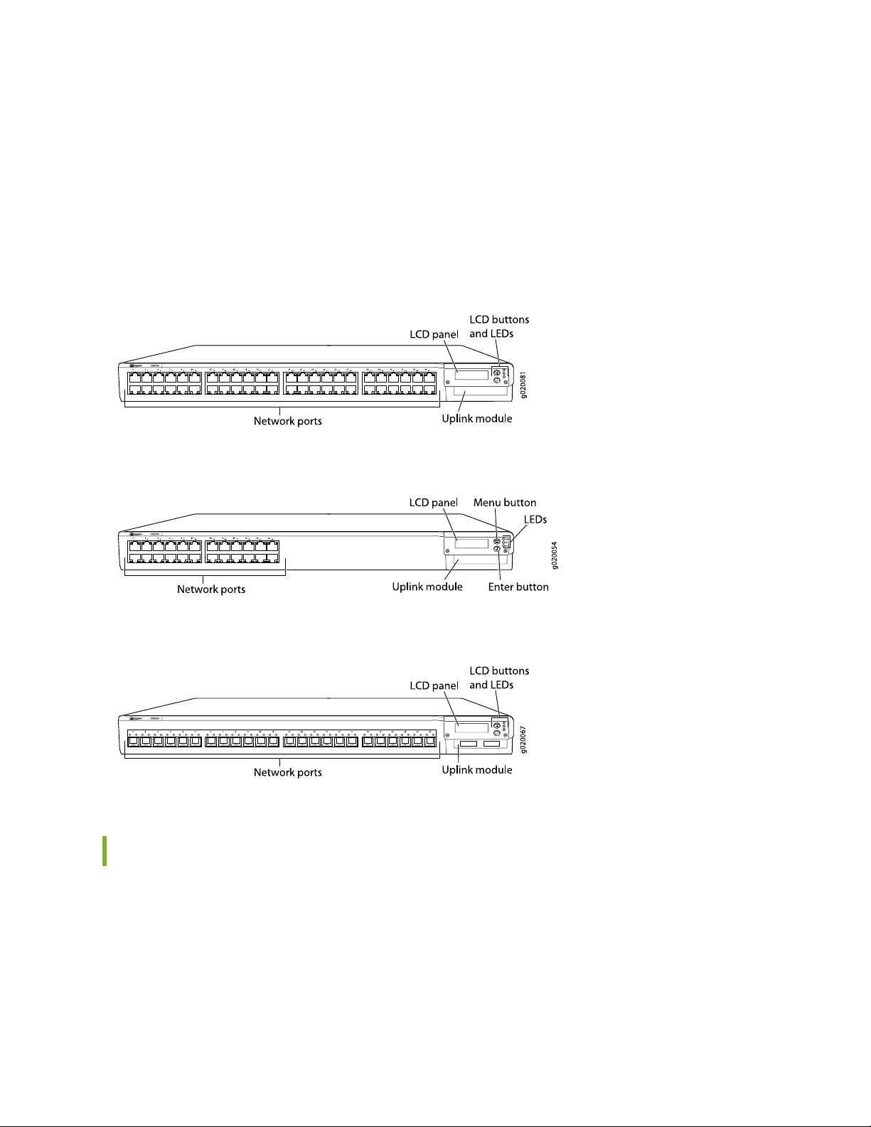
The front panel of an EX4200 switch consists of the following components:
Network ports—depending on the switch model, either:
•
10/100/1000Base-T Gigabit Ethernet ports, some or all of which are enabled for Power over Ethernet
•
(PoE)
100Base-FX/1000Base-X SFP ports for use with fiber-optic connections
•
Uplink module ports—SFP, SFP+, or XFP ports (Installing the uplink module is an optional.)
•
LCD panel and the LCD navigation buttons
•
Page 30
Chassis status LEDs
•
Network port LEDs
•
Figure 1 on page 30 shows the front panel of an EX4200 switch with 48 Gigabit Ethernet ports.
Figure 2 on page 30 shows the front panel of an EX4200 switch with 24 Gigabit Ethernet ports.
Figure 3 on page 30 shows the front panel of an EX4200-24F switch with 24 SFP ports for use with
fiber-optic connectors.
Figure 1: EX4200 Switch with 48 Gigabit Ethernet Ports
30
Figure 2: EX4200 Switch with 24 Gigabit Ethernet Ports
Figure 3: EX4200-24F Switch with 24 SFP Ports
Rear Panel of an EX4200 Switch
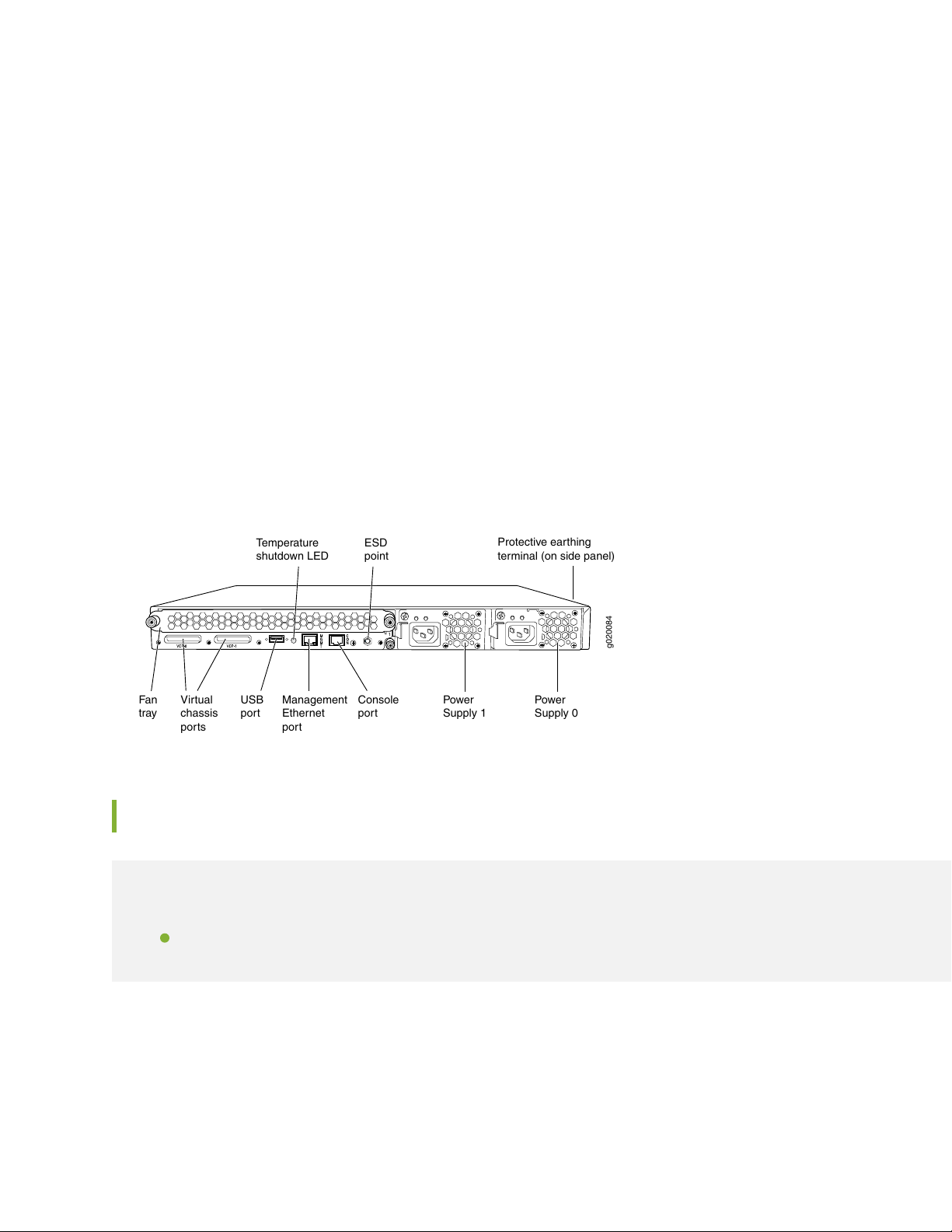
The rear panel of the EX4200 switch accomdates the following components:
Fan tray
•
Virtual Chassis ports (VCPs)
•
USB port
•
Page 31
Temperature shutdown LED
g020084
Virtual
chassis
ports
USB
port
Management
Ethernet
port
Fan
tray
Console
port
Power
Supply 1
Power
Supply 0
Protective earthing
terminal (on side panel)
ESD
point
Temperature
shutdown LED
•
Management Ethernet port
•
Console port
•
ESD point
•
Power supply or power supplies
•
Figure 4 on page 31 shows the rear panel of an EX4200 switch with power supplies and fan tray installed.
The rear panel of all the EX4200 switches except EX4200-24F-S and EX4200-48T-S switches are similar.
All EX4200 switches except the EX4200-24F-S and EX4200-48T-S switches are shipped with the power
supplies and fan tray pre-installed in the rear panel of the switch. The power supplies and the fan tray for
the EX4200-24F-S and EX4200-48T-S models are not shipped by default; you must order them separately
and install them in the rear panel. The 320 W AC power supply and the 190 W DC are flush with the
chassis. The 600 W AC power supply and 930 W AC power supply extend out of the chassis by 2.25 in.
Power cord retainer clips extend out of the power supply by 3 in.
Figure 4: EX4200 Switch Rear Panel
31
LCD Panel in EX4200 Switches
IN THIS SECTION
LCD Panel Modes | 32
The LCD panel on the front panel of the switch shows two lines of text, each of which can contain a
maximum of 16 characters. The LCD panel displays a variety of information about the switch and also
provides a menu to perform basic operations such as initial setup and reboot.
Page 32

There are two navigation buttons—Menu and Enter—to the right of the LCD panel.
See Figure 5 on page 32.
Figure 5: LCD Panel
You can configure the second line of the LCD panel to display a custom message. If the LCD panel is
configured to display a custom message, the Menu button and the Enter button are disabled. See
“Configuring the LCD Panel on EX Series Switches (CLI Procedure)” on page 160.
The LCD panel has a backlight. If the LCD panel is idle for 60 seconds, the backlight turns off. You can
turn on the backlight by pressing the Menu or Enter button once. After turning on the backlight, you can
toggle between the LCD panel menus by pressing the Menu button and navigate through the menu options
by pressing the Enter button.
32
NOTE: The chassis viewer in the J-Web interface also displays the LCD panel. From the J-Web
interface, you can view real-time status information in the LCD panel. See “Dashboard for EX
Series Switches” on page 163.
LCD Panel Modes
The LCD panel operates in four modes: boot, idle, status, and maintenance.
The LCD panel operates in boot mode during switch reboot. The boot mode displays the key milestones
in the switch boot process. The boot mode does not have any menu options. After the boot process is
complete, the LCD panel automatically reverts to the Idle menu.
In an EX4200 switch that is not a member of a Virtual Chassis, the first line of the LCD panel displays the
slot number, the role of the switch, and hostname. For a standalone EX4200 switch, the slot number is
always 00 and the role is always RE (for primary).
In an EX4200 switch that is a member of a Virtual Chassis, the first line of the LCD panel displays:
The slot number (the member ID for the Virtual Chassis member)
•
Role of the switch in a Virtual Chassis (RE for primary, BK for backup, and LC for linecard member)
•
Hostname
•
Page 33

In the idle mode, the second line displays the mode of the network ports’ Status LED and the number of
chassis alarms. The number of alarms is updated every second.
In the status mode, the second line displays:
Virtual Chassis port (VCP) status (for an EX4200 switch that is a member of a Virtual Chassis)
•
Status of the power supply
•
Status of the fan and temperature
•
Version of Junos OS for EX Series switches loaded on the switch
•
In the maintenance mode, the second line displays one of the following options that you can use to configure
and troubleshoot the switch:
System halt
•
System reboot
•
Load rescue
•
33
Request VC port (for an EX4200 switch that is a member of a Virtual Chassis)
•
Factory default
•
System EZSetup
•
Uplink Modules in EX4200 Switches
IN THIS SECTION
SFP Uplink Module | 34
SFP+ Uplink Module and SFP+ MACsec Uplink Module | 35
XFP Uplink Module | 37
EX4200 switches support four types of uplink modules:
SFP uplink module—Provides four ports for 1-gigabit small form-factor pluggable (SFP) transceivers. The
•
model number of the uplink module is EX-UM-4SFP.
SFP+ uplink module—Provides two ports for 10-gigabit small form-factor pluggable (SFP+) transceivers
•
when configured to operate in 10-gigabit mode or four ports for 1-gigabit small form-factor pluggable
Page 34

(SFP) transceivers when configured to operate in 1-gigabit mode. The model number of the uplink module
is EX-UM-2X4SFP.
SFP+ Media Access Control Security (MACsec) uplink module—Provides two ports for 10-gigabit small
•
form-factor pluggable (SFP+) transceivers when configured to operate in 10-gigabit mode or four ports
for 1-gigabit small form-factor pluggable (SFP) transceivers when configured to operate in 1-gigabit
mode. All four ports on the uplink module are MACsec-capable. The model number of the uplink module
is EX-UM-2X4SFP-M.
XFP uplink module—Provides two ports for 10-gigabit small form-factor pluggable (XFP) transceivers.
•
The model number of the uplink module is EX-UM-2XFP.
NOTE: When a new uplink module is installed in the switch or an existing uplink module is
replaced with another uplink module, the switch detects the newly installed uplink module. The
switch creates the required interfaces if the uplink module has transceivers in its ports and when
new transceivers are installed in uplink module ports.
34
NOTE: The packet forwarding process (pfem) restarts and causes traffic loss, if you:
Install an uplink module (SFP, SFP+, SFP+ MACsec, or XFP)
•
Replace an existing uplink module with another uplink module
•
Change the operating mode of an SFP+ or an SFP+ MACsec uplink module (10-gigabit to
•
1-gigabit or 1-gigabit to 10-gigabit) installed in the switch
When connecting uplink module ports, you can install an SFP uplink module at one end of the connection
and install an SFP+ uplink module configured to operate in the 1-gigabit mode at the other end. Likewise,
you can install an XFP uplink module at one end of the connection and install an SFP+ uplink module
configured to operate in the 10-gigabit mode at the other end.
SFP Uplink Module
Figure 6 on page 35 shows the SFP uplink module, which provides four ports for 1-gigabit SFP transceivers.
Page 35
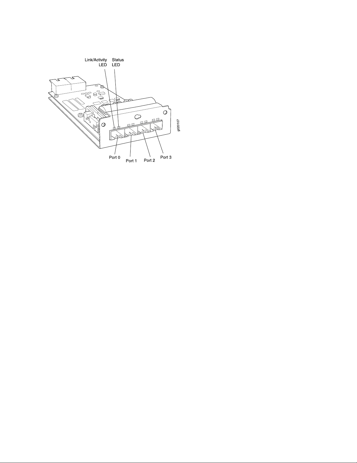
Figure 6: SFP Uplink Module
SFP uplink modules are shipped with dust covers preinstalled in the ports.
The SFP uplink module requires Junos OS for EX Series switches, Release 9.0 or later.
35
SFP+ Uplink Module and SFP+ MACsec Uplink Module
The SFP+ uplink module and the SFP+ MACsec uplink module can be used for either SFP+ or SFP
transceivers. You configure the operating mode on the module to match the type of transceiver you want
to use—for SFP+ transceivers, you configure the 10-gigabit operating mode, and for SFP transceivers, you
configure the 1-gigabit operating mode. See Setting the Mode on an SFP+ or SFP+ MACSec Uplink Module .
By default, the SFP+ uplink module and the SFP+ MACsec uplink module operate in the 10-gigabit mode
and support only SFP+ transceivers. If you have not changed the module from the default setting and you
want to use SFP+ transceivers, you do not need to configure the operating mode.
If the operating mode and the configured mode for the uplink module are different, it is shown in the
output of show chassis pic fpc-slot slot number pic-slot 1.
Figure 7 on page 36 shows the SFP+ uplink module and the SFP+ MACsec uplink module.
Page 36
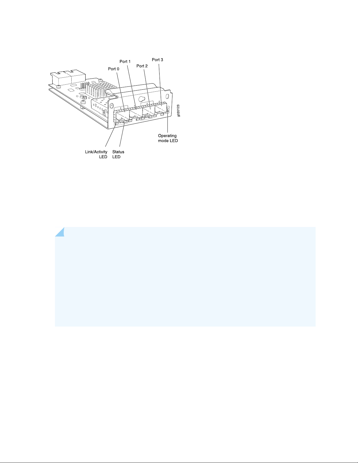
Figure 7: SFP+ and SFP+ MACsec Uplink Module
The following transceivers can be installed in the uplink module ports:
SFP+ transceivers are supported in ports 0 and 2.
•
36
SFP transceivers are supported in all four ports.
•
The ports that support SFP+ transceivers are labeled 10 G on the uplink module’s faceplate (see
Figure 7 on page 36).
NOTE: When an SFP+ uplink module or an SFP+ MACsec uplink module is operating in 10-gigabit
mode:
Only the 10-gigabit ports (ports 0 and 2) are enabled.
•
You can use only SFP+ transceivers in those ports.
•
When an SFP+ uplink module or an SFP+ MACsec uplink module is operating in 1-gigabit mode:
All four ports are enabled.
•
You can use only SFP transceivers in all four ports.
•
The SFP+ uplink module and the SFP+ MACsec uplink module have an LED on the faceplate (labeled
Operating mode LED in Figure 7 on page 36) that indicates the operating mode. If the uplink module is
operating in the 10-gigabit mode, the LED is lit. If the uplink module is operating in the 1-gigabit mode,
the LED is unlit.
SFP+ uplink modules and the SFP+ MACsec uplink modules are shipped with dust covers preinstalled in
the ports.
The SFP+ uplink module requires Junos OS for EX Series switches, Release 9.4 or later. The SFP+ MACsec
uplink module requires Junos OS for EX Series switches, Release 13.2X50-D10 or later.
Page 37
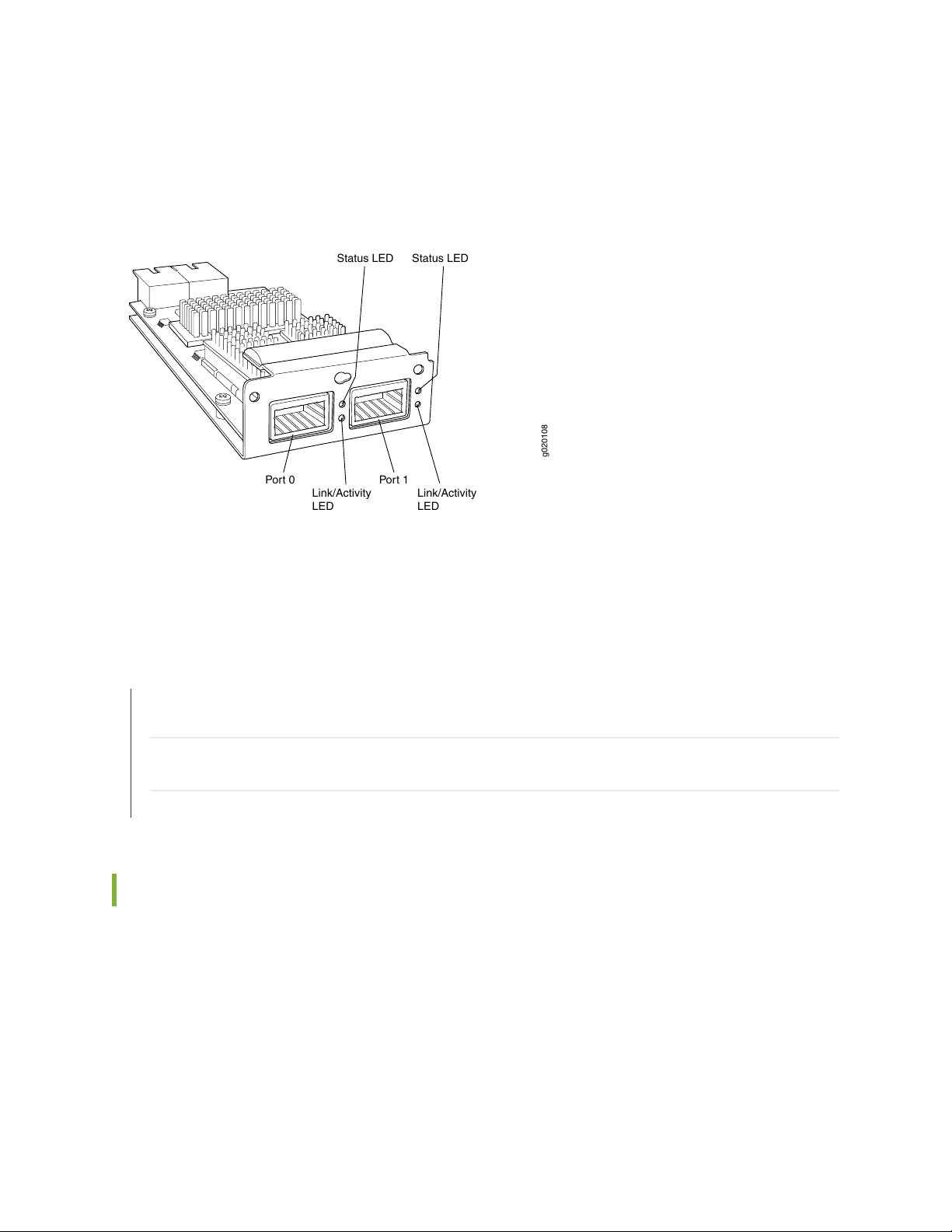
XFP Uplink Module
g020108
Link/Activity
LED
Link/Activity
LED
Status LED Status LED
Port 0 Port 1
Figure 8 on page 37 shows the XFP uplink module, which provides two ports for 10-gigabit XFP transceivers.
Figure 8: XFP Uplink Module
37
XFP uplink modules are shipped with a dust cover preinstalled in one port.
The XFP uplink module requires Junos OS for EX Series switches, Release 9.0 or later.
SEE ALSO
Example: Configuring Aggregated Ethernet High-Speed Uplinks Between an EX4200 Virtual Chassis Access
Switch and an EX4200 Virtual Chassis Distribution Switch
Example: Configuring Aggregated Ethernet High-Speed Uplinks with LACP Between an EX4200 Virtual
Chassis Access Switch and an EX4200 Virtual Chassis Distribution Switch
Troubleshooting Virtual Chassis Port Connectivity on an EX4200 Switch | 247
Chassis Status LEDs in EX4200 Switches
The front panel of an EX4200 switch has three LEDs on the far right side of the panel, next to the LCD
panel (see Figure 9 on page 38).
Page 38

Figure 9: Chassis Status LEDs in an EX4200 Switch
Table 6 on page 38 describes the chassis status LEDs in an EX4200 switch, their colors and states, and
the status they indicate. You can view the colors of the three LEDs remotely through the CLI by issuing
the operational mode command show chassis lcd.
Table 6: Chassis Status LEDs in an EX4200 Switch
State and DescriptionColorLED Label
There is no alarm or the switch is halted.UnlitALM (Alarm)
38
Red
Amber
There is a major alarm.
NOTE: When you connect power to the switch, the Alarm
(ALM) LED lights red. This behavior is normal. Plugging
an active Ethernet cable into the management (MGMT)
port on the switch completes the network link and turns
off the ALM LED. (See “Connect a Device to a Network
for Out-of-Band Management” on page 141.)
Connecting the switch to a dedicated management
console instead of a network does not affect the ALM
LED. The LED remains red until the switch is connected
to a network.
There is a minor alarm.
NOTE: The Alarm (ALM) LED lights amber if you commit
a configuration to make it active on the switch and do not
also create a rescue configuration to back it up. To save
the most recently committed configuration as the rescue
configuration, enter the operational mode command
request system configuration rescue save.
GreenSYS (System)
On steadily—Junos OS for EX Series switches has been
•
loaded on the switch.
Blinking—The switch is booting.
•
Off—The switch is powered off or is halted.
•
Page 39

Table 6: Chassis Status LEDs in an EX4200 Switch (continued)
State and DescriptionColorLED Label
39
GreenMST (Primary)
In a standalone EX4200 switch:
On steadily—The switch is functioning normally.
•
Off—The switch is powered off or is halted.
•
In a Virtual chassis configuration:
On steadily—The switch is the primary in the Virtual
•
Chassis configuration.
Blinking—The switch is the backup in the Virtual Chassis
•
configuration.
Off—The switch is a linecard member in the Virtual
•
Chassis configuration or is halted.
A major alarm (red) indicates a critical error condition that requires immediate action.
A minor alarm (amber) indicates a noncritical condition that requires monitoring or maintenance. A minor
alarm that is left unchecked might cause interruption in service or performance degradation.
NOTE: The amber glow of the Alarm LED that indicates a minor alarm closely resembles the red
glow that indicates a major alarm.
All three LEDs can be lit simultaneously.
Management Port LEDs in EX4200 Switches
The management port on EX4200 switches has two LEDs that indicate link/activity and port status (see
Figure 10 on page 40). The management port is set to full-duplex and the speed is set to 100 Mbps.
Page 40
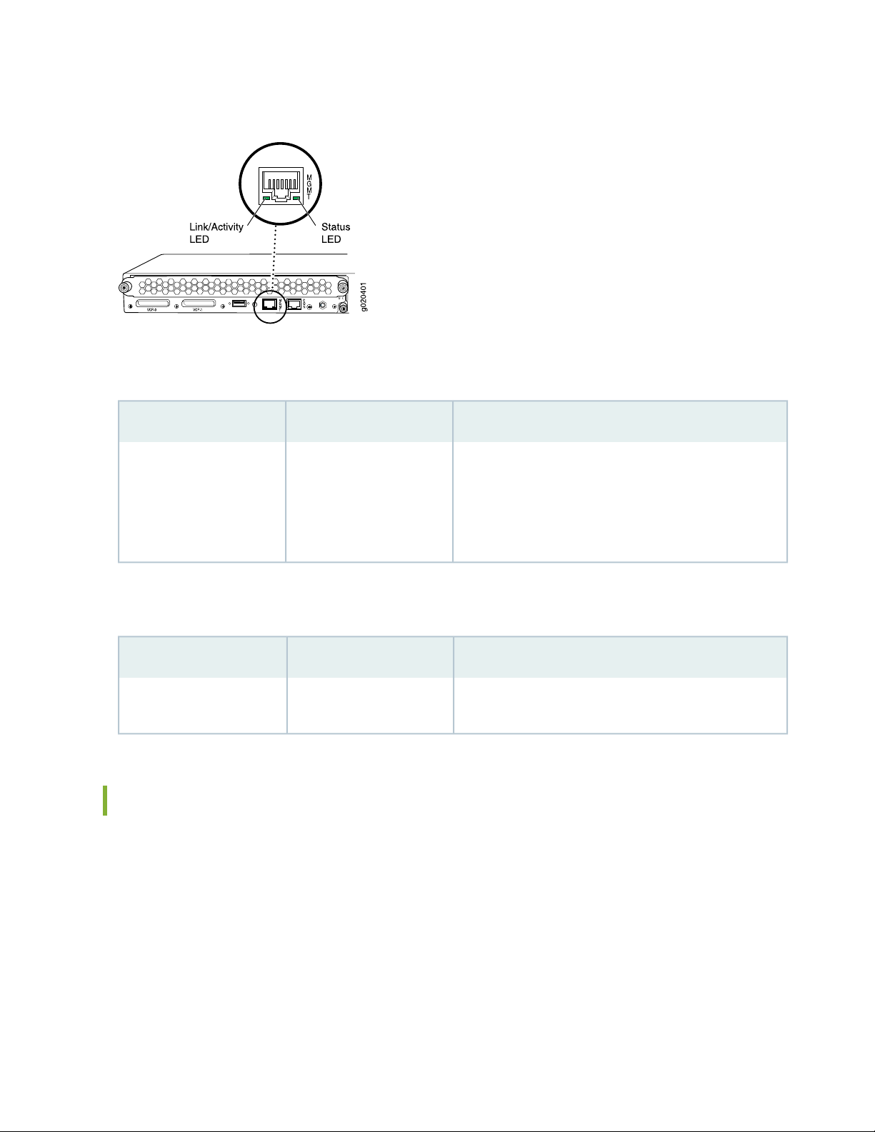
Figure 10: LEDs on the Management Port on an EX4200 Switch
Table 7 on page 40 describes the Link/Activity LED.
Table 7: Link/Activity LED on the Management Port on EX4200 Switches
State and DescriptionColorLED
40
GreenLink/Activity
Blinking—The port and the link are active, and there is
•
link activity.
On steadily—The port and the link are active, but there
•
is no link activity.
Off—The port is not active.
•
Table 8 on page 40 describes the Status LED (administrative status).
Table 8: Status LED on the Management Port on EX4200 Switches
State and DescriptionColorLED
GreenStatus
On steadily—Administrative status is enabled.
•
Off—Administrative status is disabled.
•
Network Port LEDs in EX4200 Switches
Each network port on the switch has two LEDs. The four figures in this topic show the location of those
LEDs:
Figure 11 on page 41 shows the location of the LEDs on the network ports on the front panel.
•
Figure 12 on page 41 shows the location of the LEDs on the uplink module ports on the SFP uplink
•
module.
Page 41
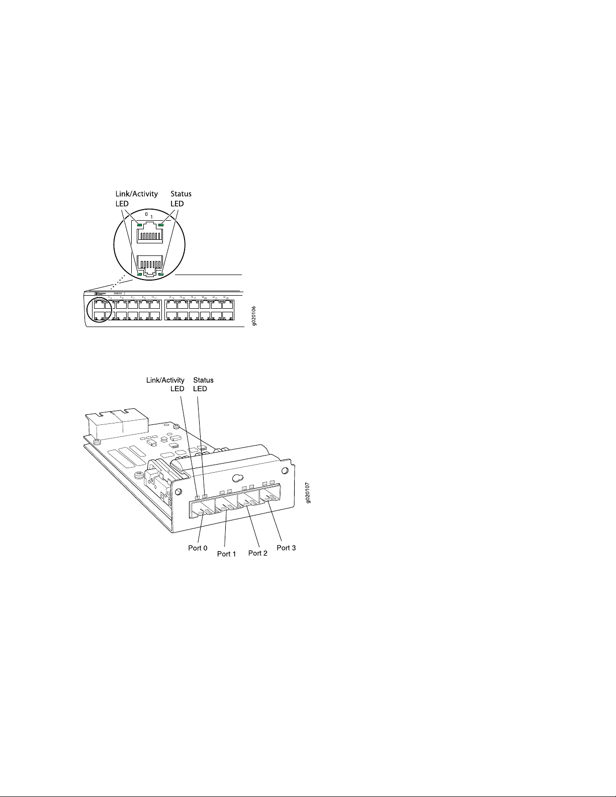
Figure 13 on page 42 shows the location of the LEDs on the uplink module ports on the SFP+ and SFP+
•
MACsec uplink modules.
Figure 14 on page 42 shows the location of the LEDs on the uplink module ports on the XFP uplink
•
module.
Figure 11: LEDs on the Network Ports on the Front Panel
41
Figure 12: LEDs on the Uplink Module Ports on the SFP Uplink Module
Page 42
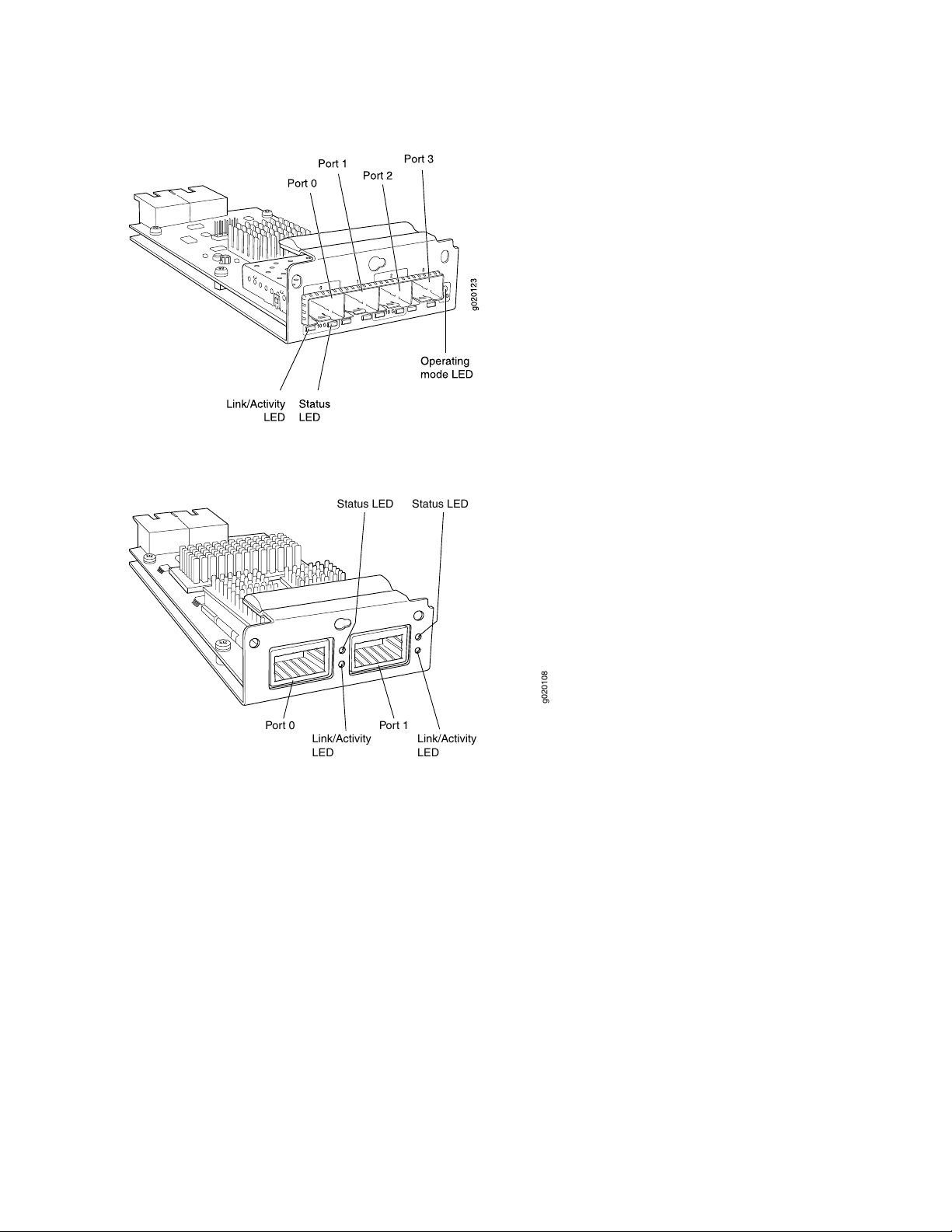
Figure 13: LEDs on the Uplink Module Ports on the SFP+ and SFP+ MACsec Uplink Modules
g020108
Link/Activity
LED
Link/Activity
LED
Status LED Status LED
Port 0 Port 1
Figure 14: LEDs on the Uplink Module Ports on the XFP Uplink Module
42
The LEDs labeled Link/Activity LED in Figure 11 on page 41, Figure 12 on page 41, Figure 13 on page 42,
and Figure 14 on page 42 indicate link activity. The LEDs labeled Status LED in Figure 11 on page 41,
Figure 12 on page 41, Figure 13 on page 42, and Figure 14 on page 42 indicate the status of one of the
four port parameters. The port parameters are administrative status, duplex mode, Power over Ethernet
(PoE) status, and speed.
Table 9 on page 43 describes the Link/Activity LED.
Page 43

Table 9: Link/Activity LED on Network Ports
43
State and DescriptionColorLED
GreenLink/Activity
Blinking—The port and the link are active, and there is
•
link activity.
On steadily—The port and the link are active, but there
•
is no link activity.
Off—The port is not active.
•
Table 10 on page 44 describes the Status LED. From the Idle menu of the LCD, use the Enter button on
the LCD panel to toggle between the ADM, DPX, POE, and SPD indicators.
Page 44

Table 10: Status LED on Network Ports
44
State and DescriptionLCD IndicatorLED
LED: ADMStatus
LED: DPX
LED: MACsec
LED: POE
Indicates the administrative status (enabled or disabled). The
status indicators are:
Green—Administrative status enabled.
•
Unlit—Administrative status disabled.
•
Indicates the duplex mode.
The uplink module ports are always set to full-duplex;
therefore, the LED is always green.
The status indicators for network ports on the front panel are:
Green—Port is set to full-duplex mode.
•
Unlit—Port is set to half-duplex mode.
•
Indicates the MACsec status (enabled or disabled). MACsec
can be enabled only if you have installed the SFP+ MACsec
uplink module. The status indicators are:
Green—MACsec is enabled on the port.
•
Unlit—MACsec is disabled on the port.
•
Indicates the PoE status on switches with PoE-enabled ports.
Here the term POE refers to both PoE and PoE+ as applicable.
PoE is not enabled on uplink module ports; therefore, the LED
for those ports is always unlit.
The status indicators for network ports on the front panel are:
Green—PoE is enabled on the port.
•
Amber—PoE is enabled on the port, but no power is drawn
•
from the port because of one of the following:
No device that draws power from the port is connected
•
to the port.
A device that draws power from the port is connected to
•
the port, but the device is not drawing any power from
the port.
Unlit—PoE is not enabled on the port.
•
Indicates the speed.LED: SPD
The speed indicators for network ports on the front panel are:
Page 45
Table 10: Status LED on Network Ports (continued)
State and DescriptionLCD IndicatorLED
One blink per second—10 Mbps
•
Two blinks per second—100 Mbps
•
Three blinks per second—1000 Mbps
•
The speed indicators for network ports on the SFP uplink
module are:
Green—1000 Mbps
•
Unlit—10/100 Mbps
•
The speed indicators for network ports on the SFP+ and SFP+
MACsec uplink module are:
Green—The speed of the transceiver installed in the port is
•
the same as the speed at which the uplink module port is
configured to operate.
Unlit—The speed of the transceiver installed in the port is
•
not the same as the speed at which the uplink module port
is configured to operate.
45
The speed of the XFP uplink module ports is always 10 Gbps,
which is also the speed of XFP transceivers, therefore, this
LED is always green on an XFP uplink module.
EX4200 Cooling System
IN THIS SECTION
Fan Tray | 46
Airflow Direction in the EX4200 Switch Chassis | 46
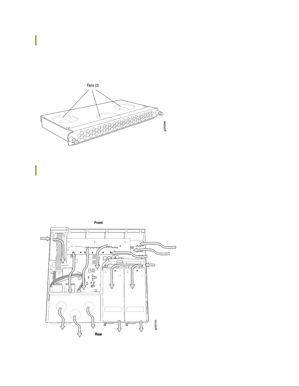
The cooling system in an EX4200 switch consists of a field-replaceable unit (FRU) fan tray with three fans
(see Figure 15 on page 46). All the EX4200 switch models, except the EX4200-24F-S and EX4200-48T-S
switches are shipped with one fan tray pre-installed in the rear panel of the switches. EX4200-24F-S and
EX4200-48T-S switches are not shipped with pre-installed fan tray; you must order them separately.
Page 46
Fan Tray
The fan tray is located at the rear of the chassis.
Figure 15: Fan Tray Used in an EX4200 Switch
46
Airflow Direction in the EX4200 Switch Chassis
The fan tray located at the rear of the chassis provides side-to-rear chassis cooling (see
Figure 16 on page 46).
Figure 16: Airflow Through the EX4200 Switch Chassis
Page 47
The fan tray used in an EX4200 switch comes with load-sharing redundancy that can tolerate a single fan
failure at room temperature (below 45° C/113° F) to still provide sufficient cooling.
Temperature sensors in the chassis monitor the temperature within the chassis. The system raises an alarm
if the fan fails or if the temperature inside the chassis rises above permitted levels. If the temperature
inside the chassis rises above the threshold, the system shuts down automatically and the temperature
shutdown LED on the rear panel is lit. You can see the status of fans and the temperature from the Show
Environment Status option in the Status menu in the LCD panel.
RELATED DOCUMENTATION
Clearance Requirements for Airflow and Hardware Maintenance for EX4200 Switches | 69
EX4200 Power System
47
IN THIS SECTION
Power Supply in EX4200 Switches | 47
AC Power Supply LEDs in EX4200 Switches | 52
DC Power Supply LEDs in EX4200 Switches | 52
Power Specifications for EX4200 Switches | 53
AC Power Cord Specifications for EX4200 Switches | 54
Power Supply in EX4200 Switches
IN THIS SECTION
AC Power Supplies | 48
DC Power Supplies | 49
PoE Power Budget and AC Power Supplies | 50
Page 48

The power supply in EX4200 switches is a hot-removable and hot-insertable field-replaceable unit (FRU)
that you can install on the rear panel without powering off the switch or disrupting the switching function.
EX4200 switches have an internal redundant power supply, making the power supply in EX4200 switches
fully redundant.
All the EX4200 switch models, except the EX4200-24F-S and EX4200-48T-S switches are shipped with
one power supply pre-installed in the rear panel of the switches. EX4200-24F-S and EX4200-48T-S
switches are not shipped with pre-installed power supplies; you must order them separately.
NOTE: This topic uses the term PoE to refer to both PoE and PoE+ unless there is a need to
distinguish between the two.
EX4200 switches use power supplies that provides two DC output voltages: 12 V for system and logic
power and 48–51 V (or higher, to compensate for voltage drops along the path from the power supplies
to the RJ-45 connector) for PoE ports.
48
NOTE: After powering on the switch, wait for at least 60 seconds before powering it off. After
powering off the switch, wait for at least 60 seconds before powering it back on.
After the switch has been powered on, it can take up to 60 seconds for status indicators—such
as LEDs on the power supply, show chassis command output, and messages on the LCD panel—to
indicate that the power supply is functioning normally. Ignore error indicators that might appear
during the first 60 seconds.
NOTE: EX4200-24PX and EX4200-48PX switches do not support the 930 W (EX-PWR-930-AC)
or the 600 W (EX-PWR-600-AC) AC power supplies that are used in the EX4200-48P and the
EX4200-24P switch models. EX4200-24PX and EX4200-48PX switches work only with the
power supplies labeled EX-PWR2-930-AC or EX-PWR3-930-AC. All EX4200 switches support
EX-PWR2-930-AC and EX-PWR3-930-AC power supplies. You can find the label on the top of
the power supply (see “Removing a Power Supply from an EX4200 Switch” on page 195).
AC Power Supplies
All the EX4200 switches that are powered by AC power supplies except the EX4200-24F-S and
EX4200-48T-S switches are shipped with one AC power supply pre-installed in the rear panel of the
switches. EX4200-24F-S and EX4200-48T-S switches are not shipped with pre-installed power supplies;
you must order them separately.
Page 49
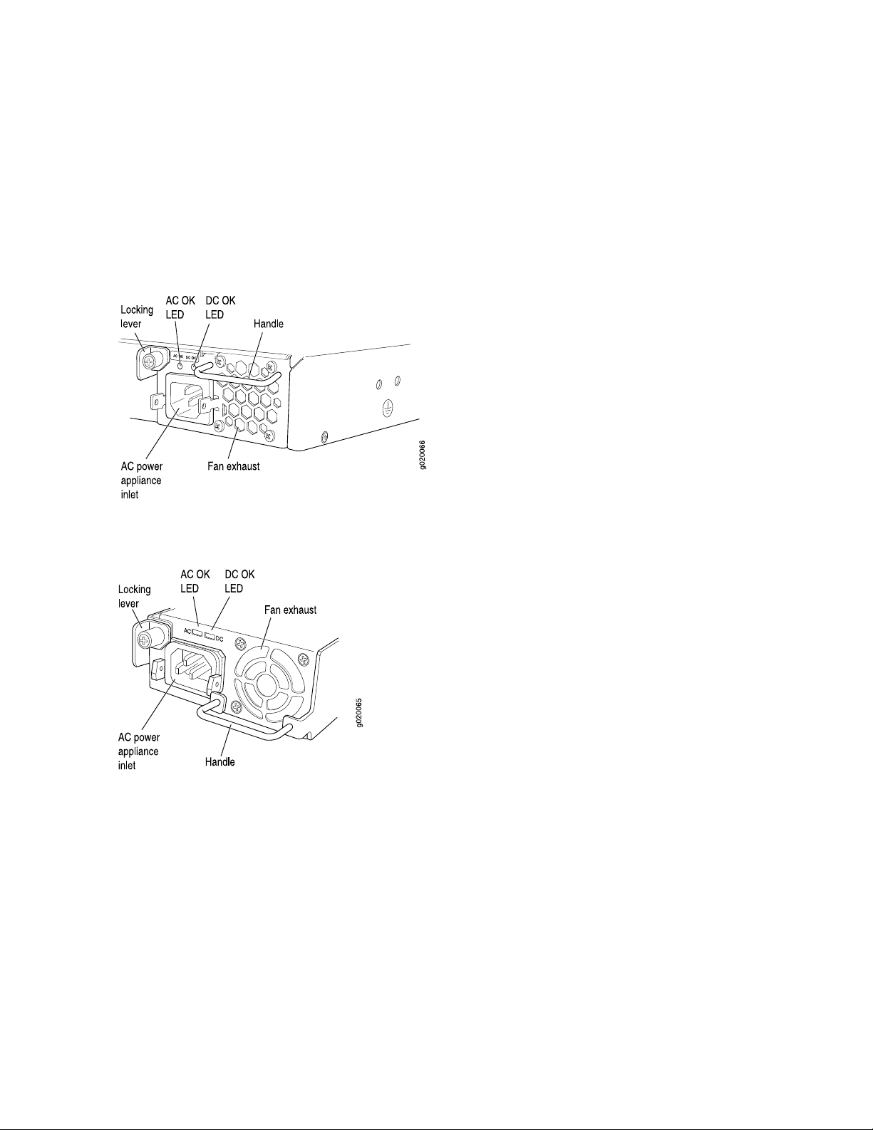
The AC power supply for the switch is available in 320 W, 600 W, and 930 W models (see
Figure 17 on page 49 and Figure 18 on page 49). The exterior of the 600 W model is identical in appearance
to that of the 930 W model. The 320 W power supply is flush with the chassis. The 600 W power supply
and 930 W power supply extend out of the chassis by 2.25 in. The power cord retainer clips extend out
of the power supply by 3 in. The number of ports on which PoE is enabled determines the minimum power
requirements of different switch models.
Figure 17: 320 W AC Power Supply
49
Figure 18: 600 W and 930 W AC Power Supplies
To avoid electrical injury, follow instructions in Installing a Power Supply in an EX3200 Switch and Removing
a Power Supply from an EX3200 Switch or “Installing a Power Supply in an EX4200 Switch” on page 197 or
“Removing a Power Supply from an EX4200 Switch” on page 195 carefully.
DC Power Supplies
All the EX4200 switches that are powered by DC power supplies except the EX4200-24F-S and
EX4200-48T-S switches are shipped with one DC power supply pre-installed in the rear panel of the
switches. EX4200-24F-S and EX4200-48T-S switches are not shipped with pre-installed power supplies;
you must order them separately.
Page 50
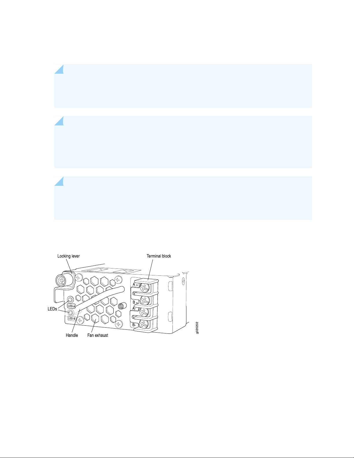
The DC power supply for the switch is available in a 190 W model, with dual input feeds for power resiliency
(see Figure 19 on page 50).
NOTE: The DC power supply in the switch does not support Power over Ethernet (PoE); you
can use either an external power injector or an AC power supply to supply power to PoE devices
that you connect to the switch.
NOTE: The DC power supply in the switch has four terminals labeled A+, B+, A–, and B– (see
Figure 19 on page 50) for connecting DC power source cables labeled positive (+) and negative (–).
The DC power supplies are shipped with jumpers from A+ input to B+ input tied together and
jumpers from A– input to B– input tied together.
NOTE: The A+ and B+ terminals are referred to as +RTN and A– and B– terminals are referred
to as –48 V in “DC Power Wiring Sequence Warning” on page 307 and “DC Power Electrical
Safety Guidelines” on page 302.
50
Figure 19: DC Power Supply
To avoid electrical injury, follow instructions in Installing a Power Supply in an EX3200 Switch and Removing
a Power Supply from an EX3200 Switch or “Installing a Power Supply in an EX4200 Switch” on page 197 or
“Removing a Power Supply from an EX4200 Switch” on page 195 carefully.
PoE Power Budget and AC Power Supplies
The PoE power budget for a PoE switch model is determined by the capacity of its power supply. For
EX4200 switches, the capacity of the power supply provided with a PoE model is sufficient to supply each
Page 51

PoE-capable port with up to 15.4 W in compliance with the IEEE 802.3af PoE standard. Table 11 on page 51
lists the power supply ratings, and the associated PoE power budgets for EX4200 switch models that
support PoE.
Starting with Junos OS Release 11.1, EX4200 switches support enhanced PoE, a Juniper Networks extension
to the IEEE 802.3af PoE standard. Enhanced PoE permits up to 18.6 W per PoE port. Because the power
supply provided with a switch is designed to supply a maximum of 15.4 W per PoE port, if you connect a
powered device that draws more than 15.4 W, the PoE power budget might not be sufficient to supply a
full 15.4 W to the remaining PoE ports.
NOTE: Switches upgraded to Junos OS Release 11.1 from a previous release require a separate
upgrade of the PoE controller software to enable enhanced PoE support.
EX4200-24PX and EX4200-48PX switches support PoE+, the IEEE 802.3at PoE standard, and permit up
to 30 W per port.
51
Table 11: Power Supply Rating and PoE Power Budget for EX4200 Switch Models
Number of PoE-enabled
PortsSwitch Model Number
PoE Power BudgetPower Supply Rating
130 W320 W8EX4200-24T
130 W320 W8EX4200-48T
130 W320 W8EX4200-48T-S
410 W600 W24EX4200-24P
740 W930 W48EX4200-48P
740 W930 W24EX4200-24PX
740 W930 W48EX4200-48PX
SEE ALSO
Connecting AC Power to an EX4200 Switch | 134
Connecting DC Power to an EX4200 Switch | 137
Page 52

AC Power Supply LEDs in EX4200 Switches
Table 12 on page 52 describes the LEDs on the AC power supplies.
Table 12: AC Power Supply LEDs
State and DescriptionLED
52
AC OK
DC OK
Off—Disconnected from power or power is not coming into the
•
power supply.
On—Power is coming into the power supply.
•
Off—Power supply is not sending out power correctly.
•
On—Power supply is sending out power correctly.
•
NOTE: If the AC OK LED and the DC OK LED are unlit, either the AC power cord is not installed
properly or the power supply fuse has failed. If the AC OK LED is lit and the DC OK LED is unlit,
the AC power supply is not installed properly or the power supply has an internal failure.
DC Power Supply LEDs in EX4200 Switches
. Table 13 on page 52 describes the LEDs on the DC power supplies.
Table 13: DC Power Supply LEDs
DescriptionColorLED Label
Inputs A and B are normal, but there is no output.RedLED A
RedLED B
Inputs A and B are normal; output is normal.GreenLED A
GreenLED B
Flash RedLED A
GreenLED B
Input A has failed because the power supply fuse has failed,
input voltage is low, or there is a loose connection; output is
normal.
Page 53

Table 13: DC Power Supply LEDs (continued)
53
DescriptionColorLED Label
GreenLED A
Flash RedLED B
Flash RedLED A
Flash RedLED B
OffLED B
Input B has failed because the power supply fuse has failed,
input voltage is low, or there is a loose connection; output is
normal.
Both inputs have failed because the power supply fuse has
failed, input voltage is low, or there is a loose connection;
output is normal.
There is no input; there is no output.OffLED A
Power Specifications for EX4200 Switches
This topic describes power specifications for power supplies for EX4200 switches.
Table 14 on page 53 provides the AC power supply electrical specifications for EX4200 switches.
Table 15 on page 54 provides the DC power supply electrical specifications for EX4200 switches.
NOTE: This topic uses the term PoE to refer to both PoE and PoE+ unless there is a need to
distinguish between the two.
Table 14: AC Power Supply Electrical Specifications
SpecificationItem
100 through 240 VACAC input voltage
50 through 60 HzAC input line frequency
AC system current rating
4 A (for switches with 8 ports equipped for Power over Ethernet (PoE) or
•
the switch with 24 100Base-FX/1000Base-SX SFP ports)
7 A (for switches with 24 ports equipped for PoE)
•
12 A (for switches with 48 ports equipped for PoE)
•
Page 54
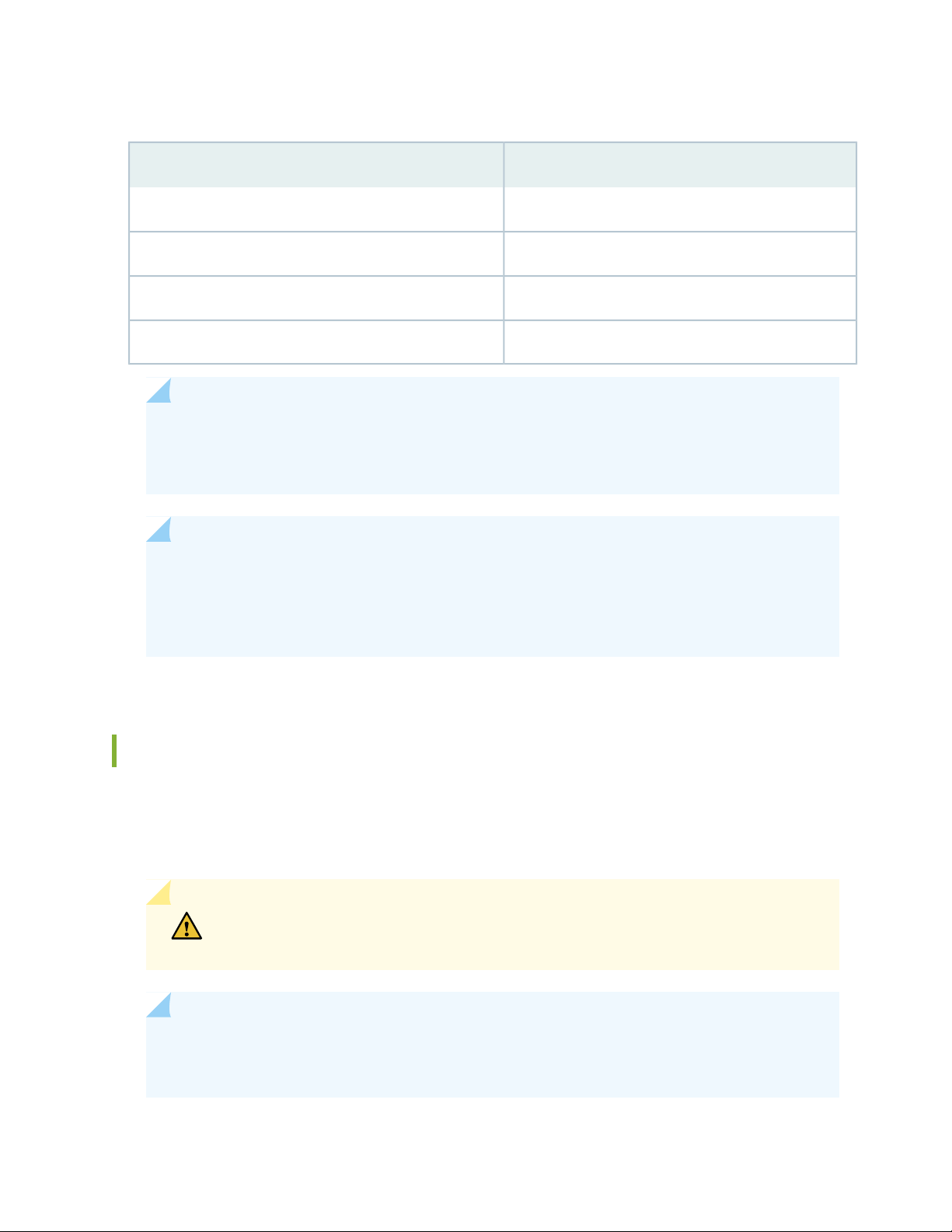
Table 15: DC Power Supply Electrical Specifications
SpecificationItem
36 through 72 VDCDC input voltage
7 A maximumDC input current
190 WPower supply output
1 ms minimumOutput holdup time
NOTE: The DC power supply in EX4200 switches does not support Power over Ethernet (PoE);
you can use either an external power injector or an AC power supply to supply power to PoE
devices that you connect to the switch.
54
NOTE: For DC power supplies, we recommend that you provide at least 7.5 A at 48 VDC and
use a facility circuit breaker rated for 10 A minimum. Doing so enables you to operate the switch
in any configuration without upgrading the power infrastructure, and ensures that the switch
functions at full capacity using multiple power supplies.
AC Power Cord Specifications for EX4200 Switches
A detachable AC power cord is supplied with the AC power supplies. The coupler is type C13 as described
by International Electrotechnical Commission (IEC) standard 60320. The plug at the male end of the power
cord fits into the power source outlet that is standard for your geographical location.
CAUTION: The AC power cord provided with each power supply is intended for use
with that power supply only and not for any other use.
NOTE: In North America, AC power cords must not exceed 4.5 meters in length, to comply with
National Electrical Code (NEC) Sections 400-8 (NFPA 75, 5-2.2) and 210-52 and Canadian
Electrical Code (CEC) Section 4-010(3). The cords supplied with the switch are in compliance.
Page 55

Table 16 on page 55 gives the AC power cord specifications for the countries and regions listed in the
table.
Table 16: AC Power Cord Specifications
Juniper Model NumberPlug StandardsElectrical SpecificationsCountry/Region
CBL-EX-PWR-C13-ARIRAM 2073 Type RA/3250 VAC, 10 A, 50 HzArgentina
55
Switzerland, and United
Kingdom)
Japan
Korea
250 VAC, 10 A, 50 HzAustralia
Hz
Hz
CBL-EX-PWR-C13-AUAS/NZZS 3112 Type
SAA/3
CBL-EX-PWR-C13-BRNBR 14136 Type BR/3250 VAC, 10 A, 50 HzBrazil
CBL-EX-PWR-C13-CHGB 1002-1996 Type PRC/3250 VAC, 10 A, 50 HzChina
CBL-EX-PWR-C13-EUCEE (7) VII Type VIIG250 VAC, 10 A, 50 HzEurope (except Italy,
CBL-EX-PWR-C13-INIS 1293 Type IND/3250 VAC, 10 A, 50 HzIndia
CBL-EX-PWR-C13-ILSI 32/1971 Type IL/3G250 VAC, 10 A, 50 HzIsrael
CBL-EX-PWR-C13-ITCEI 23-16 Type I/3G250 VAC, 10 A, 50 HzItaly
CBL-EX-PWR-C13-JPSS-00259 Type VCTF125 VAC, 12 A, 50 Hz or 60
CBL-EX-PWR-C13-KRCEE (7) VII Type VIIGK250 VAC, 10 A, 50 Hz or 60
Taiwan
250 VAC, 10 A, 50 HzSouth Africa
50 Hz
CBL-EX-PWR-C13-USNEMA 5-15 Type N5-15125 VAC, 13 A, 60 HzNorth America
CBL-EX-PWR-C13-SASABS 164/1:1992 Type
ZA/13
CBL-EX-PWR-C13-SZSEV 6534-2 Type 12G250 VAC, 10 A, 50 HzSwitzerland
CBL-EX-PWR-C13-TWNEMA 5-15P Type N5-15P125 VAC, 11 A and 15 A,
CBL-EX-PWR-C13-UKBS 1363/A Type BS89/13250 VAC, 10 A, 50 HzUnited Kingdom
Page 56

Figure 20 on page 56 illustrates the plug on the power cord for some of the countries or regions listed in
Table 16 on page 55.
Figure 20: AC Plug Types
56
Page 57

2
CHAPTER
Site Planning, Preparation, and
Specifications
Site Preparation Checklist for EX4200 Switches | 58
EX4200 Site Guidelines and Requirements | 59
EX4200 Network Cable and Transceiver Planning | 70
EX4200 Management Cable Specifications and Pinouts | 78
EX4200 Virtual Chassis | 99
Page 58

Site Preparation Checklist for EX4200 Switches
The checklist in Table 17 on page 58 summarizes the tasks you need to perform when preparing a site for
EX4200 switch installation.
Table 17: Site Preparation Checklist
Environment
“Environmental Requirements and Specifications for EX Series Switches” on page 60Verify that environmental factors such as
temperature and humidity do not exceed
switch tolerances.
Power
58
Measure distance between external power
sources and switch installation site.
Locate sites for connection of system
grounding.
requirements.
Hardware Configuration
you want to install.
Rack or Cabinet
Verify that your rack or cabinet meets the
minimum requirements for the installation
of the switch.
required space clearances.
“Power Specifications for EX4200 Switches” on page 53Calculate the power consumption and
“EX4200 Switches Hardware Overview” on page 19Choose the number and types of switches
“Rack Requirements” on page 66
“Cabinet Requirements” on page 67
“Clearance Requirements for Airflow and Hardware Maintenance for EX4200 Switches” on page 69Plan rack or cabinet location, including
Secure the rack or cabinet to the floor and
building structure.
Wall
Page 59
Table 17: Site Preparation Checklist (continued)
“Requirements for Mounting an EX4200 Switch on a Desktop or Wall” on page 68Verify that the wall meets the minimum
requirements for the installation of the
switch.
“Clearance Requirements for Airflow and Hardware Maintenance for EX4200 Switches” on page 69Verify that there is appropriate clearance in
your selected location.
Cables
Acquire cables and connectors:
Determine the number of cables needed
•
based on your planned configuration.
Review the maximum distance supported
•
for each cable. Choose the length of cable
based on the distance between the
hardware components being connected.
59
Plan the cable routing and management.
EX4200 Site Guidelines and Requirements
IN THIS SECTION
Environmental Requirements and Specifications for EX Series Switches | 60
General Site Guidelines | 65
Site Electrical Wiring Guidelines | 65
Rack Requirements | 66
Cabinet Requirements | 67
Requirements for Mounting an EX4200 Switch on a Desktop or Wall | 68
Clearance Requirements for Airflow and Hardware Maintenance for EX4200 Switches | 69
Page 60

Environmental Requirements and Specifications for EX Series Switches
The switch must be installed in a rack or cabinet housed in a dry, clean, well-ventilated, and
temperature-controlled environment.
Ensure that these environmental guidelines are followed:
The site must be as dust-free as possible, because dust can clog air intake vents and filters, reducing the
•
efficiency of the switch cooling system.
Maintain ambient airflow for normal switch operation. If the airflow is blocked or restricted, or if the
•
intake air is too warm, the switch might overheat, leading to the switch temperature monitor shutting
down the switch to protect the hardware components.
Table 18 on page 60 provides the required environmental conditions for normal switch operation.
Table 18: EX Series Switch Environmental Tolerances
Environment Tolerance
Switch or
device SeismicTemperatureRelative HumidityAltitude
60
EX2200-C
EX2200
(except
EX2200-C
switches)
EX2300-C
No performance
degradation up to
5,000 feet (1524
meters)
No performance
degradation up to
10,000 feet
(3048 meters)
No performance
degradation up to
5,000 feet
(1524 meters)
Normal operation ensured
in the relative humidity
range 10% through 85%
(noncondensing)
Normal operation ensured
in the relative humidity
range 10% through 85%
(noncondensing)
Normal operation ensured
in the relative humidity
range 10% through 85%
(noncondensing)
Normal operation ensured
in the temperature range
32° F (0° C) through 104°
F (40° C) at altitudes up to
5,000 ft (1,524 m).
For information about
extended temperature SFP
transceivers supported on
EX2200 switches, see
Pluggable Transceivers
Supported on EX2200
Switches.
Normal operation ensured
in the temperature range
32° F (0° C) through 113°
F (45° C)
Normal operation ensured
in the temperature range
32° F (0° C) through 104°
F (40° C)
Complies with Zone
4 earthquake
requirements as per
GR-63, Issue 4.
Complies with Zone
4 earthquake
requirements as per
GR-63, Issue 4.
Complies with Zone
4 earthquake
requirements as per
GR-63, Issue 4.
Page 61

Table 18: EX Series Switch Environmental Tolerances (continued)
Environment Tolerance
Switch or
device SeismicTemperatureRelative HumidityAltitude
61
EX2300
(except
EX2300-C
switches)
EX3200
EX3300
EX3400
No performance
degradation up to
13,000 feet
(3962 meters) at
104° F (40° C) as
per GR-63
No performance
degradation up to
10,000 feet
(3048 meters)
No performance
degradation up to
10,000 feet
(3048 meters)
No performance
degradation up to
10,000 feet
(3048 meters)
Normal operation ensured
in the relative humidity
range 10% through 85%
(noncondensing)
Normal operation ensured
in the relative humidity
range 10% through 85%
(noncondensing)
Normal operation ensured
in the relative humidity
range 10% through 85%
(noncondensing)
Normal operation ensured
in the relative humidity
range 10% through 85%
(noncondensing)
Normal operation ensured
in the temperature range
32° F (0° C) through 113°
F (45° C)
Normal operation ensured
in the temperature range
32° F (0° C) through 113°
F (45° C)
Normal operation ensured
in the temperature range
32° F (0° C) through 113°
F (45° C)
Normal operation ensured
in the temperature range
32° F (0° C) through 113°
F (45° C)
Complies with Zone
4 earthquake
requirements as per
GR-63, Issue 4.
Complies with Zone
4 earthquake
requirements as per
GR-63, Issue 4.
Complies with Zone
4 earthquake
requirements as per
GR-63, Issue 4.
Complies with Zone
4 earthquake
requirements as per
GR-63, Issue 4.
EX4200
No performance
degradation up to
10,000 feet
(3048 meters)
Normal operation ensured
in the relative humidity
range 10% through 85%
(noncondensing)
Normal operation ensured
in the temperature range
32° F (0° C) through 113°
F (45° C)
Complies with Zone
4 earthquake
requirements as per
GR-63, Issue 4.
Page 62

Table 18: EX Series Switch Environmental Tolerances (continued)
Environment Tolerance
Switch or
device SeismicTemperatureRelative HumidityAltitude
62
EX4300
The
maximum
thermal
output for
EX4300-48T
is 423
BTU/hour
and for
EX4300-48P
is 5844
BTU/hour.
EX4500
EX4300 switches
except the
EX4300-48MP
model— No
performance
degradation up to
10,000 feet
(3048 meters)
EX4300-48MP
model— No
performance
degradation up to
6,000 feet
(1829 meters)
No performance
degradation up to
10,000 feet
(3048 meters)
EX4300 switches except
the EX4300-48MP
model— Normal operation
ensured in the relative
humidity range 10%
through 85%
(noncondensing)
EX4300-48MP model—
Normal operation ensured
in the relative humidity
range 5% through 90%
(noncondensing)
Normal operation ensured
in the relative humidity
range 10% through 85%
(noncondensing)
Normal operation ensured
in the temperature range
32° F (0° C) through 113°
F (45° C)
Normal operation ensured
in the temperature range
32° F (0° C) through 113°
F (45° C)
Complies with Zone
4 earthquake
requirements as per
GR-63, Issue 4.
Complies with Zone
4 earthquake
requirements as per
GR-63, Issue 4.
EX4550
No performance
degradation up to
10,000 feet
(3048 meters)
Normal operation ensured
in the relative humidity
range 10% through 85%
(noncondensing)
EX4550-32F switches—
•
Normal operation
ensured in the
temperature range 32°
F (0° C) through 113° F
(45° C)
EX4550-32T switches—
•
Normal operation is
ensured in the
temperature range 32°
F through 104° F (40° C)
Complies with Zone
4 earthquake
requirements as per
GR-63, Issue 4.
Page 63

Table 18: EX Series Switch Environmental Tolerances (continued)
Environment Tolerance
Switch or
device SeismicTemperatureRelative HumidityAltitude
63
EX4600
EX4650
No performance
degradation to
6,562 feet
(2000 meters)
No performance
degradation to
6,000 feet
(1829 meters)
Normal operation ensured
in the relative humidity
range 5% through 90%,
noncondensing
Short-term operation
•
ensured in the relative
humidity range 5%
through 93%,
noncondensing
NOTE: As defined in
NEBS GR-63-CORE,
Issue 4, short-term
events can be up to 96
hours in duration but
not more than 15 days
per year.
Normal operation ensured
in the relative humidity
range 10% through 85%
(condensing)
Normal operation
•
ensured in the
temperature range 32°
F (0° C) through 113° F
(45° C)
Nonoperating storage
•
temperature in shipping
container: – 40° F
(–40° C) through 158° F
(70° C)
Normal operation is ensured
in the temperature range
32° F (0° C) through 104°
F (40° C)
Complies with Zone
4 earthquake
requirements per
NEBS GR-63-CORE,
Issue 4.
Complies with Zone
4 earthquake
requirements as per
GR-63, Issue 4.
EX6210
EX8208
EX8216
No performance
degradation up to
10,000 feet
(3048 meters)
No performance
degradation up to
10,000 feet
(3048 meters)
No performance
degradation up to
10,000 feet
(3048 meters)
Normal operation ensured
in the relative humidity
range 10% through 85%
(noncondensing)
Normal operation ensured
in the relative humidity
range 10% through 85%
(noncondensing)
Normal operation ensured
in the relative humidity
range 10% through 85%
(noncondensing)
Normal operation is ensured
in the temperature range
32° F (0° C) through 104°
F (40° C)
Normal operation is ensured
in the temperature range
32° F (0° C) through 104°
F (40° C)
Normal operation is ensured
in the temperature range
32° F (0° C) through 104°
F (40° C)
Complies with Zone
4 earthquake
requirements as per
GR-63, Issue 4.
Complies with Zone
4 earthquake
requirements as per
GR-63, Issue 4.
Complies with Zone
4 earthquake
requirements as per
GR-63, Issue 4.
Page 64

Table 18: EX Series Switch Environmental Tolerances (continued)
Environment Tolerance
Switch or
device SeismicTemperatureRelative HumidityAltitude
64
EX9204
EX9208
EX9214
No performance
degradation up to
10,000 feet
(3048 meters)
No performance
degradation up to
10,000 feet
(3048 meters)
No performance
degradation up to
10,000 feet
(3048 meters)
Normal operation ensured
in the relative humidity
range 5% through 90%
(noncondensing)
Normal operation ensured
in the relative humidity
range 5% through 90%
(noncondensing)
Normal operation ensured
in the relative humidity
range 5% through 90%
(noncondensing)
Normal operation is ensured
in the temperature range
32° F (0° C) through 104°
F (40° C)
Nonoperating storage
temperature in shipping
container: – 40° F (–40° C)
to 158° F (70° C)
Normal operation is ensured
in the temperature range
32° F (0° C) through 104°
F (40° C)
Nonoperating storage
temperature in shipping
container: – 40° F (–40° C)
to 158° F (70° C)
Normal operation is ensured
in the temperature range
32° F (0° C) through 104°
F (40° C)
Complies with Zone
4 earthquake
requirements as per
GR-63.
Complies with Zone
4 earthquake
requirements as per
GR-63.
Complies with Zone
4 earthquake
requirements as per
GR-63.
EX9251
The
maximum
thermal
output is
1705
BTU/hour
(500 W).
No performance
degradation up to
10,000 ft (3048 m)
Normal operation ensured
in relative humidity range
of 5% to 90%,
noncondensing
Nonoperating storage
temperature in shipping
container: – 40° F (–40° C)
through 158° F (70° C)
Normal operation ensured
in temperature range of 32°
F (0° C) to 104° F (40° C)
Nonoperating storage
temperature in shipping
container: – 40° F (–40° C)
to 158° F (70° C)
Complies with
Telcordia
Technologies Zone
4 earthquake
requirements
Page 65

Table 18: EX Series Switch Environmental Tolerances (continued)
Environment Tolerance
Switch or
device SeismicTemperatureRelative HumidityAltitude
65
XRE200
No performance
degradation up to
10,000 feet
(3048 meters)
Normal operation ensured
in the relative humidity
range 10% through 85%
(noncondensing)
Normal operation ensured
in the temperature range
41° F (5° C) through 104°
F (40° C)
Complies with Zone
4 earthquake
requirements as per
GR-63, Issue 4.
NOTE: Install EX Series switches only in restricted areas, such as dedicated equipment rooms
and equipment closets, in accordance with Articles 110– 16, 110– 17, and 110– 18 of the
National Electrical Code, ANSI/NFPA 70.
General Site Guidelines
Efficient device operation requires proper site planning and maintenance and proper layout of the equipment,
rack or cabinet (if used), and wiring closet.
To plan and create an acceptable operating environment for your device and prevent environmentally
caused equipment failures:
Keep the area around the chassis free from dust and conductive material, such as metal flakes.
•
Follow prescribed airflow guidelines to ensure that the cooling system functions properly and that
•
exhaust from other equipment does not blow into the intake vents of the device.
Follow the prescribed electrostatic discharge (ESD) prevention procedures to prevent damaging the
•
equipment. Static discharge can cause components to fail completely or intermittently over time.
Install the device in a secure area, so that only authorized personnel can access the device.
•
Site Electrical Wiring Guidelines
Table 19 on page 66 describes the factors you must consider while planning the electrical wiring at your
site.
Page 66

WARNING: You must provide a properly grounded and shielded environment and use
electrical surge-suppression devices.
Avertissement Vous devez établir un environnement protégé et convenablement mis
à la terre et utiliser des dispositifs de parasurtension.
Table 19: Site Electrical Wiring Guidelines
Site Wiring
Factor
Guidelines
66
Signaling
limitations
Radio
frequency
interference
Electromagnetic
compatibility
If your site experiences any of the following problems, consult experts in electrical surge suppression
and shielding:
Improperly installed wires cause radio frequency interference (RFI).
•
Damage from lightning strikes occurs when wires exceed recommended distances or pass between
•
buildings.
Electromagnetic pulses (EMPs) caused by lightning damage unshielded conductors and electronic
•
devices.
To reduce or eliminate RFI from your site wiring, do the following:
Use a twisted-pair cable with a good distribution of grounding conductors.
•
If you must exceed the recommended distances, use a high-quality twisted-pair cable with one
•
ground conductor for each data signal when applicable.
If your site is susceptible to problems with electromagnetic compatibility (EMC), particularly from
lightning or radio transmitters, seek expert advice.
Some of the problems caused by strong sources of electromagnetic interference (EMI) are:
Destruction of the signal drivers and receivers in the device
•
Electrical hazards as a result of power surges conducted over the lines into the equipment
•
Rack Requirements
You can mount the device on two-post racks or four-post racks.
Rack requirements consist of:
Rack type
•
Mounting bracket hole spacing
•
Page 67

Rack size and strength
•
Rack connection to the building structure
•
Table 20 on page 67 provides the rack requirements and specifications.
Table 20: Rack Requirements and Specifications
GuidelinesRack Requirement
67
Rack type
Mounting bracket
hole spacing
Rack size and
strength
Rack connection to
building structure
You can mount the device on a rack that provides bracket holes or hole patterns spaced at 1-U
(1.75 in. or 4.45 cm) increments and meets the size and strength requirements to support the
weight.
A U is the standard rack unit defined by the Electronic Components Industry Association
(http://www.ecianow.org).
The holes in the mounting brackets are spaced at 1-U (1.75 in. or 4.45 cm), so that the device
can be mounted in any rack that provides holes spaced at that distance.
Ensure that the rack complies with the size and strength standards of a 19-in. rack as defined
•
by the Electronic Components Industry Association (http://www.ecianow.org).
Ensure that the rack rails are spaced widely enough to accommodate the external dimensions
•
of the device chassis. The outer edges of the front mounting brackets extend the width of
the chassis to 19 in. (48.2 cm).
The rack must be strong enough to support the weight of the device.
•
Ensure that the spacing of rails and adjacent racks provides for proper clearance around the
•
device and rack.
Secure the rack to the building structure.
•
If your geographical area is earthquake-prone, secure the rack to the floor.
•
Secure the rack to the ceiling brackets as well as wall or floor brackets for maximum stability.
•
SEE ALSO
Rack-Mounting and Cabinet-Mounting Warnings | 276
Cabinet Requirements
You can mount the device in a cabinet that contains a 19-in. rack.
Cabinet requirements consist of:
Page 68

Cabinet size
•
Clearance requirements
•
Cabinet airflow requirements
•
Table 21 on page 68 provides the cabinet requirements and specifications.
Table 21: Cabinet Requirements and Specifications
GuidelinesCabinet Requirement
68
Cabinet size
Cabinet clearance
Cabinet airflow
requirements
The minimum cabinet size is 36 in. (91.4 cm) depth. Large cabinets improve airflow
•
and reduce chances of overheating.
The outer edges of the front mounting brackets extend the width of the chassis to
•
19 in. (48.2 cm).
The minimum total clearance inside the cabinet is 30.7 in. (78 cm) between the inside
•
of the front door and the inside of the rear door.
When you mount the device in a cabinet, ensure that ventilation through the cabinet is
sufficient to prevent overheating.
Ensure adequate cool air supply to dissipate the thermal output of the device or
•
devices.
Ensure that the hot air exhaust of the chassis exits the cabinet without recirculating
•
into the device. An open cabinet (without a top or doors) that employs hot air exhaust
extraction from the top ensures the best airflow through the chassis. If the cabinet
contains a top or doors, perforations in these elements assist with removing the hot
air exhaust.
Install the device in the cabinet in a way that maximizes the open space on the side
•
of the chassis that has the hot air exhaust.
Route and dress all cables to minimize the blockage of airflow to and from the chassis.
•
Ensure that the spacing of rails and adjacent cabinets is such that there is proper
•
clearance around the device and cabinet.
A cabinet larger than the minimum required provides better airflow and reduces the
•
chance of overheating.
Requirements for Mounting an EX4200 Switch on a Desktop or Wall
You can install the switch on or under a desk or other level surface or on a wall. When choosing a location,
allow at least 6 in. (15.2 cm) of clearance between the front and back of the chassis and adjacent equipment
or walls.
Ensure that the wall onto which the switch is installed is stable and securely supported.
Page 69
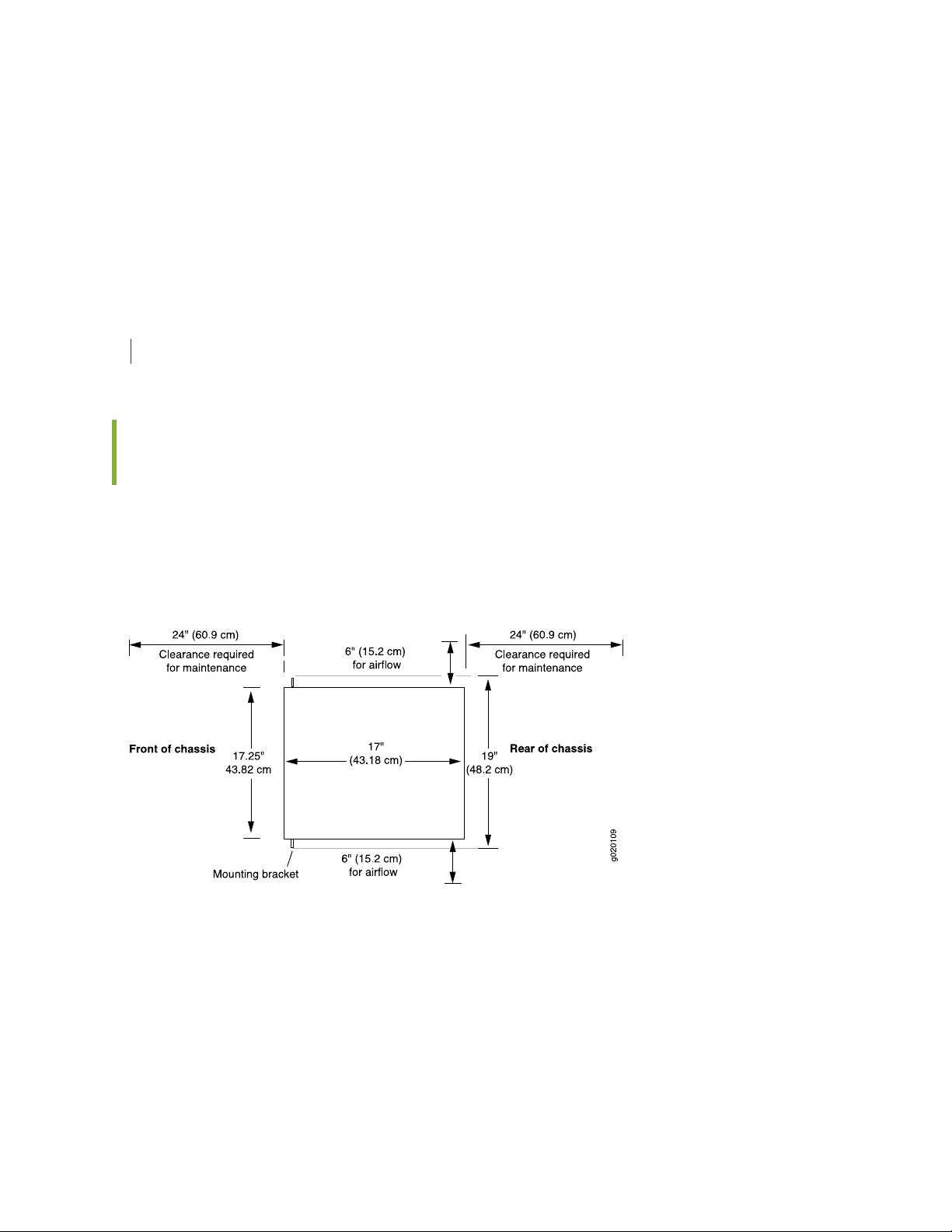
If you are mounting the switch in sheetrock (wall board with a gypsum plaster core) or in wall board not
backed by wall studs, use hollow wall anchors capable of supporting the combined weight of two fully
loaded chassis. Insert the screws into wall studs wherever possible to provide added support for the chassis.
Use the wall-mount kit from Juniper Networks to mount the switch on a wall. The wall-mount kit is not
part of the standard package and must be ordered separately.
SEE ALSO
Mounting an EX4200 Switch on a Wall | 124
Clearance Requirements for Airflow and Hardware Maintenance for EX4200 Switches
69
When planning the site for installing an EX4200 switch, you must allow sufficient clearance around the
installed switch (see Figure 21 on page 69).
Figure 21: Clearance Requirements for Airflow and Hardware Maintenance for EX4200 Switches
Page 70
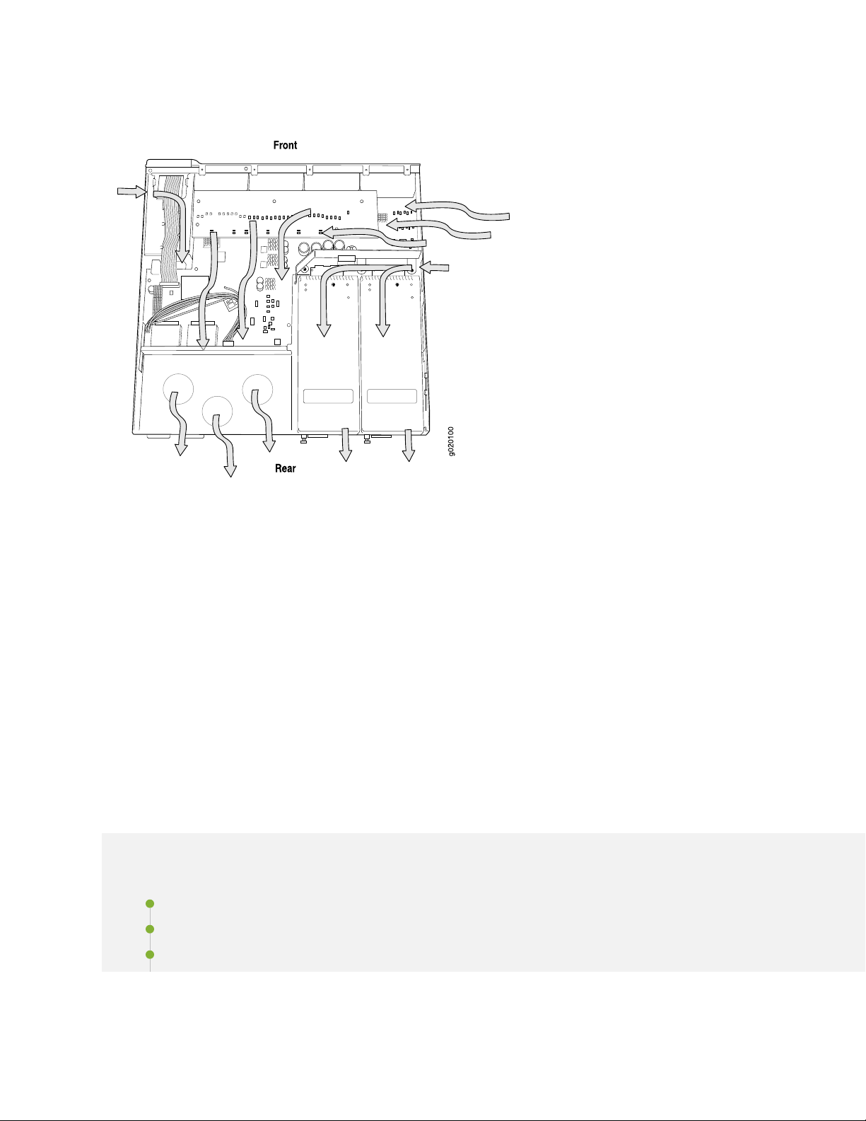
Figure 22: Airflow Through the EX4200 Switch Chassis
70
Allow at least 6 in. (15.2 cm) of clearance on the side between devices that have fans or blowers installed.
•
Allow 2.8 in. (7 cm) between the side of the chassis and any non-heat-producing surface such as a wall.
If you are mounting the switch on a rack or cabinet with other equipment, or if you are placing it on the
•
desktop or floor near other equipment, ensure that the exhaust from other equipment does not blow
into the intake vents of the chassis.
Leave at least 24 in. (61 cm) both in front of and behind the switch. For service personnel to remove
•
and install hardware components, you must leave adequate space at the front and back of the switch.
NEBS GR-63 recommends at least 30 in. (76.2 cm) in front of the rack or cabinet and 24 in. (61 cm)
behind the rack or cabinet.
EX4200 Network Cable and Transceiver Planning
IN THIS SECTION
Pluggable Transceivers Supported on EX4200 Switches | 71
SFP+ Direct Attach Copper Cables for EX Series Switches | 72
Understanding EX Series Switches Fiber-Optic Cable Signal Loss, Attenuation, and Dispersion | 74
Page 71

Calculating the Fiber-Optic Cable Power Budget for EX Series Devices | 75
Calculating the Fiber-Optic Cable Power Margin for EX Series Devices | 76
Pluggable Transceivers Supported on EX4200 Switches
Optional uplink modules for EX4200 switches support SFP, SFP+, or XFP transceivers. You can find the
list of transceivers supported on EX4200 switches and information about those transceivers at the Hardware
Compatibility Tool page for EX4200.
NOTE: We recommend that you use only optical transceivers and optical connectors purchased
from Juniper Networks with your Juniper Networks device.
71
CAUTION: If you face a problem running a Juniper Networks device that uses a
third-party optic or cable, the Juniper Networks Technical Assistance Center (JTAC)
can help you diagnose the source of the problem. Your JTAC engineer might recommend
that you check the third-party optic or cable and potentially replace it with an equivalent
Juniper Networks optic or cable that is qualified for the device.
The Gigabit Ethernet SFP, SFP+, or XFP transceivers installed in EX4200 switches support digital optical
monitoring (DOM): You can view the diagnostic details for these transceivers by issuing the operational
mode CLI command show interfaces diagnostics optics.
NOTE: The transceivers support DOM even if they are installed in uplink module ports configured
as Virtual Chassis ports.
Page 72
SFP+ Direct Attach Copper Cables for EX Series Switches
IN THIS SECTION
Cable Specifications | 72
List of DAC Cables Supported on EX Series Switches | 73
Standards Supported by These Cables | 73
Small form-factor pluggable plus transceiver (SFP+) direct attach copper (DAC) cables, also known as
Twinax cables, are suitable for in-rack connections between servers and switches. They are suitable for
short distances, making them ideal for highly cost-effective networking connectivity within a rack and
between adjacent racks.
72
NOTE: We recommend that you use only SFP+ DAC cables purchased from Juniper Networks
with your Juniper Networks device.
CAUTION: If you face a problem running a Juniper Networks device that uses a
third-party optic or cable, the Juniper Networks Technical Assistance Center (JTAC)
can help you diagnose the source of the problem. Your JTAC engineer might recommend
that you check the third-party optic or cable and potentially replace it with an equivalent
Juniper Networks optic or cable that is qualified for the device.
Cable Specifications
EX Series switches support SFP+ passive DAC cables. The passive Twinax cable is a straight cable with
no active electronic components. EX Series switches support 1 m, 3 m, 5 m, and 7 m long SFP+ passive
DAC cables. See Figure 23 on page 73.
Page 73

Figure 23: SFP+ Direct Attach Copper Cables for EX Series Switches
The cables are hot-removable and hot-insertable: You can remove and replace them without powering
off the switch or disrupting switch functions. A cable comprises a low-voltage cable assembly that connects
directly into two 10-Gigabit Ethernet ports, one at each end of the cable. The cables use high-performance
integrated duplex serial data links for bidirectional communication and are designed for data rates of up
to 10 Gbps.
List of DAC Cables Supported on EX Series Switches
For the list of DAC cables supported on EX Series switches and the specifications of these cables, see:
EX2300—Hardware Compatibility Tool page for EX2300
•
73
EX3200—Hardware Compatibility Tool page for EX3200
•
EX3300—Hardware Compatibility Tool page for EX3300
•
EX3400—Hardware Compatibility Tool page for EX3400
•
EX4200—Hardware Compatibility Tool page for EX4200
•
EX4300—Hardware Compatibility Tool page for EX4300
•
EX4500—Hardware Compatibility Tool page for EX4500
•
EX4550—Hardware Compatibility Tool page for EX4550
•
EX4600—Hardware Compatibility Tool page for EX4600
•
EX8208—Hardware Compatibility Tool page for EX8208
•
EX8216—Hardware Compatibility Tool page for EX8216
•
EX9251—Hardware Compatibility Tool page for EX9251
•
EX9253—Hardware Compatibility Tool page for EX9253
•
Standards Supported by These Cables
The cables comply with the following standards:
SFP mechanical standard SFF-843— see ftp://ftp.seagate.com/sff/SFF-8431.PDF.
•
Electrical interface standard SFF-8432— see ftp://ftp.seagate.com/sff/SFF-8432.PDF.
•
Page 74

SFP+ Multi-Source Alliance (MSA) standards
•
Understanding EX Series Switches Fiber-Optic Cable Signal Loss, Attenuation, and Dispersion
IN THIS SECTION
Signal Loss in Multimode and Single-Mode Fiber-Optic Cable | 74
Attenuation and Dispersion in Fiber-Optic Cable | 74
To determine the power budget and power margin needed for fiber-optic connections, you need to
understand how signal loss, attenuation, and dispersion affect transmission. EX Series switches use various
types of network cable, including multimode and single-mode fiber-optic cable.
74
Signal Loss in Multimode and Single-Mode Fiber-Optic Cable
Multimode fiber is large enough in diameter to allow rays of light to reflect internally (bounce off the walls
of the fiber). Interfaces with multimode optics typically use LEDs as light sources. However, LEDs are not
coherent light sources. They spray varying wavelengths of light into the multimode fiber, which reflects
the light at different angles. Light rays travel in jagged lines through a multimode fiber, causing signal
dispersion. When light traveling in the fiber core radiates into the fiber cladding (layers of lower refractive
index material in close contact with a core material of higher refractive index), higher-order mode loss
(HOL) occurs. Together, these factors reduce the transmission distance of multimode fiber compared to
that of single-mode fiber.
Single-mode fiber is so small in diameter that rays of light reflect internally through one layer only. Interfaces
with single-mode optics use lasers as light sources. Lasers generate a single wavelength of light, which
travels in a straight line through the single-mode fiber. Compared to multimode fiber, single-mode fiber
has a higher bandwidth and can carry signals for longer distances. It is consequently more expensive.
Exceeding the maximum transmission distances can result in significant signal loss, which causes unreliable
transmission.
Attenuation and Dispersion in Fiber-Optic Cable
An optical data link functions correctly provided that modulated light reaching the receiver has enough
power to be demodulated correctly. Attenuation is the reduction in strength of the light signal during
Page 75

transmission. Passive media components such as cables, cable splices, and connectors cause attenuation.
Although attenuation is significantly lower for optical fiber than for other media, it still occurs in both
multimode and single-mode transmission. An efficient optical data link must transmit enough light to
overcome attenuation.
Dispersion is the spreading of the signal over time. The following two types of dispersion can affect signal
transmission through an optical data link:
Chromatic dispersion, which is the spreading of the signal over time caused by the different speeds of
•
light rays.
Modal dispersion, which is the spreading of the signal over time caused by the different propagation
•
modes in the fiber.
For multimode transmission, modal dispersion, rather than chromatic dispersion or attenuation, usually
limits the maximum bit rate and link length. For single-mode transmission, modal dispersion is not a factor.
However, at higher bit rates and over longer distances, chromatic dispersion limits the maximum link length.
An efficient optical data link must have enough light to exceed the minimum power that the receiver
requires to operate within its specifications. In addition, the total dispersion must be within the limits
specified for the type of link in Telcordia Technologies document GR-253-CORE (Section 4.3) and
International Telecommunications Union (ITU) document G.957.
75
When chromatic dispersion is at the maximum allowed, its effect can be considered as a power penalty in
the power budget. The optical power budget must allow for the sum of component attenuation, power
penalties (including those from dispersion), and a safety margin for unexpected losses.
Calculating the Fiber-Optic Cable Power Budget for EX Series Devices
To ensure that fiber-optic connections have sufficient power for correct operation, calculate the link's
power budget when planning fiber-optic cable layout and distances to ensure that fiber-optic connections
have sufficient power for correct operation. The power budget is the maximum amount of power the link
can transmit. When you calculate the power budget, you use a worst-case analysis to provide a margin of
error, even though all the parts of an actual system do not operate at the worst-case levels.
To calculate the worst-case estimate for fiber-optic cable power budget (PB) for the link:
1. Determine values for the link's minimum transmitter power (PT) and minimum receiver sensitivity (PR).
For example, here, (PT) and (PR) are measured in decibels, and decibels are referred to one milliwatt
(dBm).
PT= – 15 dBm
PR= – 28 dBm
Page 76

NOTE: See the specifications for your transmitter and receiver to find the minimum transmitter
power and minimum receiver sensitivity.
2. Calculate the power budget (PB) by subtracting (PR) from (PT):
– 15 dBm – (–28 dBm) = 13 dBm
Calculating the Fiber-Optic Cable Power Margin for EX Series Devices
Calculate the link's power margin when planning fiber-optic cable layout and distances to ensure that
fiber-optic connections have sufficient signal power to overcome system losses and still satisfy the minimum
input requirements of the receiver for the required performance level. The power margin (PM) is the amount
of power available after attenuation or link loss (LL) has been subtracted from the power budget (PB).
76
When you calculate the power margin, you use a worst-case analysis to provide a margin of error, even
though all the parts of an actual system do not operate at worst-case levels. A power margin (PM) greater
than zero indicates that the power budget is sufficient to operate the receiver and that it does not exceed
the maximum receiver input power. This means the link will work. A (PM) that is zero or negative indicates
insufficient power to operate the receiver. See the specification for your receiver to find the maximum
receiver input power.
Before calculating the power margin:
Calculate the power budget (see “Calculating the Fiber-Optic Cable Power Budget for EX Series Devices”
•
on page 75).
To calculate the worst-case estimate for the power margin (PM) for the link:
1. Determine the maximum value for link loss (LL) by adding estimated values for applicable link-loss
factors—for example, use the sample values for various factors as provided in Table 22 on page 76
(here, the link is 2 km long and multimode, and the (PB) is 13 dBm):
Table 22: Estimated Values for Factors Causing Link Loss
Sample (LL) Calculation ValuesEstimated Link-Loss ValueLink-Loss Factor
Higher-order mode losses (HOL)
Multimode—0.5 dBm
•
Single mode—None
•
0.5 dBm
•
0 dBm
•
Page 77

Table 22: Estimated Values for Factors Causing Link Loss (continued)
77
Sample (LL) Calculation ValuesEstimated Link-Loss ValueLink-Loss Factor
Modal and chromatic dispersion
Fiber attenuation
Multimode—None, if product of
•
bandwidth and distance is less than
500 MHz/km
Single mode—None
•
0.5 dBmConnector
0.5 dBmSplice
Multimode—1 dBm/km
•
Single mode—0.5 dBm/km
•
0 dBm
•
0 dBm
•
This example assumes 5 connectors.
Loss for 5 connectors:
(5) * (0.5 dBm) = 2.5 dBm
This example assumes 2 splices. Loss for
two splices:
(2) * (0.5 dBm) = 1 dBm
This example assumes the link is 2 km
long. Fiber attenuation for 2 km:
(2 km) * (1.0 dBm/km) = 2 dBm
•
(2 km) * (0.5 dBm/km) = 1 dBm
•
1 dBm1 dBmClock Recovery Module (CRM)
NOTE: For information about the actual amount of signal loss caused by equipment and
other factors, see your vendor documentation for that equipment.
2. Calculate the (PM) by subtracting (LL) from (PB):
PB– LL = P
M
(13 dBm) – (0.5 dBm [HOL]) – ((5) * (0.5 dBm)) – ((2) * (0.5 dBm)) – ((2 km) * (1.0 dBm/km)) – (1 dB
[CRM]) = P
13 dBm – 0.5 dBm – 2.5 dBm – 1 dBm – 2 dBm – 1 dBm = P
M
M
PM= 6 dBm
The calculated power margin is greater than zero, indicating that the link has sufficient power for
transmission. Also, the power margin value does not exceed the maximum receiver input power. Refer
to the specification for your receiver to find the maximum receiver input power.
Page 78

EX4200 Management Cable Specifications and Pinouts
IN THIS SECTION
Management Cable Specifications | 78
Console Port Connector Pinout Information | 79
USB Port Specifications for an EX Series Switch | 79
RJ-45 Management Port Connector Pinout Information | 80
RJ-45 Port, SFP Port, SFP+ Port, QSFP+ Port, and QSFP28 Port Connector Pinout Information | 81
RJ-45 to DB-9 Serial Port Adapter Pinout Information | 85
Uplink Modules Connector Pinout Information for EX4200 Switches | 86
Virtual Chassis Ports Connector Pinout Information for EX4200 Switches | 95
78
Management Cable Specifications
Table 23 on page 78 lists the specifications for the cables that connect the console and management ports
to management devices.
Table 23: Specifications of Cables to Connect to Management Devices
Additional InformationReceptacleCable SpecificationsPorts
RJ-45 Console port
Management Ethernet port
Mini-USB Type-B Console
port
RJ-45CAT5e UTP (unshielded
twisted pair) cable
RJ-45Ethernet cable with an
RJ-45 connector
Mini-USBMini-USB cable with
standard-A and Mini-USB
Type-B (5-pin) connector
“Connect a Device to a
Management Console Using
an RJ-45 Connector” on
page 142
“Connect a Device to a
Network for Out-of-Band
Management” on page 141
Page 79

Console Port Connector Pinout Information
The console port on a Juniper Networks device is an RS-232 serial interface that uses an RJ-45 connector
to connect to a console management device. The default baud rate for the console port is 9600 baud.
Table 24 on page 79 provides the pinout information for the RJ-45 console connector.
NOTE: If your laptop or desktop PC does not have a DB-9 plug connector pin and you want to
connect your laptop or desktop PC directly to a device, use a combination of the RJ-45 to DB-9
socket adapter and a USB to DB-9 plug adapter. You must provide the USB to DB-9 plug adapter.
Table 24: Console Port Connector Pinout Information
DescriptionSignalPin
79
Request to sendRTS Output1
Data terminal readyDTR Output2
Transmit dataTxD Output3
Signal groundSignal Ground4
Signal groundSignal Ground5
Receive dataRxD Input6
Data carrier detectCD Input7
CTS InputNC8
USB Port Specifications for an EX Series Switch
The following Juniper Networks USB flash drives have been tested and are officially supported for the
USB port on all EX Series switches:
RE-USB-1G-S
•
RE-USB-2G-S
•
RE-USB-4G-S
•
Page 80

CAUTION: Any USB memory product not listed as supported for EX Series switches
has not been tested by Juniper Networks. The use of any unsupported USB memory
product could expose your EX Series switch to unpredictable behavior. Juniper
Networks Technical Assistance Center (JTAC) can provide only limited support for
issues related to unsupported hardware. We strongly recommend that you use only
supported USB flash drives.
All USB flash drives used on EX Series switches must have the following features:
USB 2.0 or later.
•
Formatted with a FAT or MS-DOS file system.
•
If the switch is running Junos OS Release 9.5 or earlier, the formatting method must use a primary boot
•
record. Microsoft Windows formatting, by default, does not use a primary boot record. See the
documentation for your USB flash drive for information about how your USB flash drive is formatted.
80
RJ-45 Management Port Connector Pinout Information
Table 25 on page 80 provides the pinout information for the RJ-45 connector for the management port
on Juniper Networks devices.
Table 25: RJ-45 Management Port Connector Pinout Information
DescriptionSignalPin
Transmit/receive data pair 1TRP1+1
Transmit/receive data pair 1TRP1—2
Transmit/receive data pair 2TRP2+3
Transmit/receive data pair 3TRP3+4
Transmit/receive data pair 3TRP3—5
Transmit/receive data pair 2TRP2—6
Transmit/receive data pair 4TRP4+7
Transmit/receive data pair 4TRP4—8
Page 81

RJ-45 Port, SFP Port, SFP+ Port, QSFP+ Port, and QSFP28 Port Connector Pinout Information
The tables in this topic describe the connector pinout information for the RJ-45, QSFP+, QSFP28, SFP+,
and SFP ports.
Table 26 on page 81—10/100/1000BASE-T Ethernet network port connector pinout information
•
Table 27 on page 81—SFP network port connector pinout information
•
Table 28 on page 83—SFP+ network port connector pinout information
•
Table 29 on page 84—QSFP+ and QSFP28 network module ports connector pinout information
•
Table 26: 10/100/1000BASE-T Ethernet Network Port Connector Pinout Information
DescriptionSignalPin
81
TRP1+1
TRP1-2
TRP2+3
TRP2-6
Transmit/receive data pair 1
Negative Vport (in PoE models)
Transmit/receive data pair 1
Negative Vport (in PoE models)
Transmit/receive data pair 2
Positive Vport (in PoE models)
Transmit/receive data pair 3TRP3+4
Transmit/receive data pair 3TRP3-5
Transmit/receive data pair 2
Positive Vport (in PoE models)
Transmit/receive data pair 4TRP4+7
Transmit/receive data pair 4TRP4-8
Table 27: SFP Network Port Connector Pinout Information
DescriptionSignalPin
Module transmitter groundVeeT1
Page 82

Table 27: SFP Network Port Connector Pinout Information (continued)
DescriptionSignalPin
Module transmitter faultTX_Fault2
Transmitter disabledTX_Disable3
2-wire serial interface data lineSDA4
2-wire serial interface clockSCL-5
Module absentMOD_ABS6
Rate selectRS7
Receiver loss of signal indicationRX_LOS8
82
Module receiver groundVeeR9
Module receiver groundVeeR10
Module receiver groundVeeR11
Receiver inverted data outputRD-12
Receiver noninverted data outputRD+13
Module receiver groundVeeR14
Module receiver 3.3 V supplyVccR15
Module transmitter 3.3 V supplyVccT16
Module transmitter groundVeeT17
Transmitter noninverted data inputTD+18
Transmitter inverted data inputTD-19
Module transmitter groundVeeT20
Page 83

Table 28: SFP+ Network Port Connector Pinout Information
DescriptionSignalPin
Module transmitter groundVeeT1
Module transmitter faultTX_Fault2
Transmitter disabledTX_Disable3
2-wire serial interface data lineSDA4
2-wire serial interface clockSCL-5
Module absentMOD_ABS6
Rate select 0, optionally controls SFP+ module receiverRS07
83
Receiver loss of signal indicationRX_LOS8
Rate select 1, optionally controls SFP+ transmitterRS19
Module receiver groundVeeR10
Module receiver groundVeeR11
Receiver inverted data outputRD-12
Receiver noninverted data outputRD+13
Module receiver groundVeeR14
Module receiver 3.3-V supplyVccR15
Module transmitter 3.3-V supplyVccT16
Module transmitter groundVeeT17
Transmitter noninverted data inputTD+18
Transmitter inverted data inputTD-19
Module transmitter groundVeeT20
Page 84

Table 29: QSFP+ and QSFP28 Network Port Connector Pinout Information
SignalPin
GND1
TX2n2
TX2p3
GND4
TX4n5
TX4p6
GND7
84
ModSelL8
LPMode_Reset9
VccRx10
SCL11
SDA12
GND13
RX3p14
RX3n15
GND16
RX1p17
RX1n18
GND19
GND20
RX2n21
Page 85

Table 29: QSFP+ and QSFP28 Network Port Connector Pinout Information (continued)
SignalPin
RX2p22
GND23
RX4n24
RX4p25
GND26
ModPrsL27
IntL28
85
VccTx29
Vcc130
Reserved31
GND32
TX3p33
TX3n34
GND35
TX1p36
TX1n37
GND38
RJ-45 to DB-9 Serial Port Adapter Pinout Information
The console port is an RS-232 serial interface that uses an RJ-45 connector to connect to a management
device such as a laptop or a desktop PC. If your laptop or desktop PC does not have a DB-9 plug connector
Page 86

pin and you want to connect your laptop or desktop PC to the device, use a combination of the RJ-45 to
DB-9 socket adapter along with a USB to DB-9 plug adapter.
Table 30 on page 86 provides the pinout information for the RJ-45 to DB-9 serial port adapter.
Table 30: RJ-45 to DB-9 Serial Port Adapter Pinout Information
SignalDB-9 PinSignalRJ-45 Pin
CTS8RTS1
DSR6DTR2
RxD2TxD3
GND5GND4
TxD3RxD6
86
DTR4DSR7
RTS7CTS8
Uplink Modules Connector Pinout Information for EX4200 Switches
EX4200 switches have a field-replaceable unit (FRU) uplink module on the front panel. Table 31 on page 86
provides the uplink modules connector pinout information.
NOTE: You can use these ports to connect an access switch to a distribution switch. You can
also use optional uplink module ports to connect members of a Virtual Chassis across multiple
wiring closets.
Table 31: Uplink Modules Connector Pinout Information
Pin NamePin Number
GNDA1
GNDA2
GNDA3
Page 87

Table 31: Uplink Modules Connector Pinout Information (continued)
Pin NamePin Number
GNDA4
GNDA5
GNDA6
GNDA7
GNDA8
GNDA9
GNDA10
87
GNDA11
GNDA12
GNDA13
GNDA14
Uplink_I2C_SCKA15
GNDA16
Uplink_PDA17
GNDA18
POWER (12V)A19
GNDA20
GNDB1
XAUI0_RX0NB2
GNDB3
XAUI0_RX2NB4
Page 88

Table 31: Uplink Modules Connector Pinout Information (continued)
Pin NamePin Number
Uplink_P25_LED2B5
XAUI1_RX0NB6
Uplink_P27_LED2B7
XAUI1_RX2NB8
GNDB9
SRX28NB10
Uplink_XAUI_XMDIOB11
88
SRX26NB12
GNDB13
SGMIIRXNB14
Uplink_I2C_RstB15
Uplink_IntrB16
Uplink_Pwr_EnB17
Uplink_P26_LED0B18
POWER (12V)B19
POWER (12V)B20
GNDC1
XAUI0_RX0PC2
GNDC3
XAUI0_RX2PC4
GNDC5
Page 89

Table 31: Uplink Modules Connector Pinout Information (continued)
Pin NamePin Number
XAUI1_RX0PC6
GNDC7
XAUI1_RX2PC8
GNDC9
SRX28PC10
GNDC11
SRX26PC12
89
GNDC13
SGMIIRXPC14
CPU_UPLINK_MDCC15
Uplink_I2C_SDAC16
CPU_UPLINK_MDIOC17
Uplink_P26_LED1C18
UPLNK_PWR_OKC19
POWER (12V)C20
GNDD1
GNDD2
XAUI0_TX1ND3
GNDD4
XAUI0_TX3ND5
GNDD6
Page 90

Table 31: Uplink Modules Connector Pinout Information (continued)
Pin NamePin Number
XAUI1_TX1ND7
GNDD8
XAUI1_TX3ND9
GNDD10
STX27ND11
GNDD12
STX25ND13
90
GNDD14
Uplink_RstD15
GNDD16
Uplink_Status_LED0D17
GNDD18
POWER (12V)D19
GNDD20
GNDE1
XAUI0_TX0NE2
XAUI0_TX1PE3
XAUI0_TX2NE4
XAUI0_TX3PE5
XAUI1_TX0NE6
XAUI1_TX1PE7
Page 91

Table 31: Uplink Modules Connector Pinout Information (continued)
Pin NamePin Number
XAUI1_TX2NE8
XAUI1_TX3PE9
STX28NE10
STX27PE11
STX26NE12
STX25PE13
SGMIITXNE14
91
Uplink_Hotswap_LEDE15
Uplink_Spare_IntrE16
Uplink_Status_LED1E17
Uplink_P27_LED0E18
POWER (12V)E19
POWER (12V)E20
GNDF1
XAUI0_TX0PF2
GNDF3
XAUI0_TX2PF4
GNDF5
XAUI1_TX0PF6
GNDF7
XAUI_TX2PF8
Page 92

Table 31: Uplink Modules Connector Pinout Information (continued)
Pin NamePin Number
GNDF9
STX28PF10
GNDF11
STX26PF12
GNDF13
SGMIITXPF14
GNDF15
92
Uplink_Expander_IntrF16
GNDF17
Uplink_P27_LED1F18
GNDF19
POWER (12V)F20
GNDG1
GNDG2
XAUI0_RX1NG3
GNDG4
XAUI0_RX3NG5
GNDG6
XAUI1_RX1NG7
GNDG8
XAUI1_RX3NG9
Page 93

Table 31: Uplink Modules Connector Pinout Information (continued)
Pin NamePin Number
GNDG10
SRX27NG11
GNDG12
SRX25NG13
GNDG14
GNDG15
GNDG16
93
Uplink_P25_LED0G17
GNDG18
POWER (12V)G19
GNDG20
Uplink_PD_LoopbackH1
GNDH2
XAUI0_RX1PH3
GNDH4
XAUI0_RX3PH5
Uplink_P26_ LED2H6
XAUI1_RX1PH7
Uplink_P28_ LED2H8
XAUI1_RX3PH9
GNDH10
Page 94

Table 31: Uplink Modules Connector Pinout Information (continued)
Pin NamePin Number
SRX27PH11
Uplink_XAUI_MDCH12
SRX25PH13
GNDH14
Serial_RXH15
GNDH16
Uplink_P25_LED1H17
94
Uplink_P28_LED0H18
POWER (12V)H19
POWER (12V)H20
GNDI1
GNDI2
GNDI3
GNDI4
GNDI5
GNDI6
GNDI7
GNDI8
GNDI9
GNDI10
GNDI11
Page 95

Table 31: Uplink Modules Connector Pinout Information (continued)
Pin NamePin Number
GNDI12
GNDI13
GNDI14
GNDI15
Serial_TXI16
GNDI17
Uplink_P28_LED1I18
95
GNDI19
POWER (12V)I20
SEE ALSO
Uplink Modules in EX4200 Switches | 33
Virtual Chassis Ports Connector Pinout Information for EX4200 Switches
EX4200 switches use a 68-pin connector cable to interconnect switches to form a Virtual Chassis. The
cable is provided with the switch. Table 32 on page 95 provides the Virtual Chassis ports (VCPs) connector
pinout information.
Table 32: Virtual Chassis Ports (VCPs) Connector Pinout Information
Pin NamePin Number
GNDA1
P1TXP0A2
P1TXN0A3
Page 96

Table 32: Virtual Chassis Ports (VCPs) Connector Pinout Information (continued)
Pin NamePin Number
GNDA4
P1TXP1A5
P1TXN1A6
GNDA7
P1TXP2A8
P1TXN2A9
GNDA10
96
P1TXP3A11
P1TXN3A12
GNDA13
NCA14
NCA15
GNDA16
NCA17
NCA18
NCA19
NCA20
NCA21
GNDA22
P2TXP0A23
P2TXN0A24
Page 97

Table 32: Virtual Chassis Ports (VCPs) Connector Pinout Information (continued)
Pin NamePin Number
GNDA25
P2TXP1A26
P2TXN1A27
GNDA28
P2TXP2A29
P2TXN2A30
GNDA31
97
P2TXP3A32
P2TXN3A33
GNDA34
GNDB1
P1RXP0B2
P1RXN0B3
GNDB4
P1RXP1B5
P1RXN1B6
GNDB7
P1RXP2B8
P1RXN2B9
GNDB10
P1RXP3B11
Page 98

Table 32: Virtual Chassis Ports (VCPs) Connector Pinout Information (continued)
Pin NamePin Number
P1RXN3B12
GNDB13
NCB14
NCB15
NCB16
NCB17
NCB18
98
NCB19
NCB20
NCB21
GNDB22
P2RXP0B23
P2RXN0B24
GNDB25
P2RXP1B26
P2RXN1B27
GNDB28
P2RXP2B29
P2RXN2B30
GNDB31
P2RXP3B32
Page 99

Table 32: Virtual Chassis Ports (VCPs) Connector Pinout Information (continued)
Pin NamePin Number
P2RXN3B33
GNDB34
SEE ALSO
Understanding Virtual Chassis Components
Connecting a Virtual Chassis Cable to an EX4200 Switch | 231
EX4200 Virtual Chassis
99
IN THIS SECTION
Understanding EX4200, EX4500, and EX4550 Virtual Chassis Hardware Configurations | 99
Planning EX4200, EX4500, and EX4550 Virtual Chassis | 103
Virtual Chassis Cabling Configuration Examples for EX4200 Switches | 105
Understanding EX4200, EX4500, and EX4550 Virtual Chassis Hardware Configurations
IN THIS SECTION
Ports Used to Interconnect Virtual Chassis Members | 100
Number of Switches, Required Software Releases, and Member Roles That You Configure in the Virtual
Chassis | 101
Virtual Chassis Module | 102
Switch Role and Member ID on the LCD Panel | 102
Page 100

You can interconnect EX4200 switches together to form a Virtual Chassis composed exclusively of EX4200
switches. You can interconnect EX4500 switches together to form a Virtual Chassis composed exclusively
of EX4500 switches. You can interconnect EX4550 switches together to form a Virtual Chassis composed
exclusively of EX4550 switches. You can also interconnect EX4200 switches with EX4500 switches or
with EX4550 switches or with both switches to form a mixed Virtual Chassis.
Ports Used to Interconnect Virtual Chassis Members
You can use the following ports to connect Virtual Chassis members:
On EX4200 switches:
•
The dedicated Virtual Chassis ports (VCPs) on each switch
•
SFP, SFP+, or XFP uplink module ports configured as VCPs
•
SFP network ports on EX4200-24F switches configured as VCPs
•
On EX4500 switches:
•
100
The dedicated VCPs on the Virtual Chassis module
•
SFP+ network ports configured as VCPs
•
SFP+ uplink module ports configured as VCPs
•
On EX4550 switches:
•
The dedicated VCPs on the Virtual Chassis module
•
SFP+ network ports configured as VCPs
•
SFP+ expansion module ports configured as VCPs
•
10GBASE-T network ports configured as VCPs
•
10GBASE-T expansion module ports configured as VCPs
•
40G QSFP+ expansion module ports configured as VCPs
•
NOTE: You can use the 10GBASE-T Ethernet network ports, 10GBASE-T expansion module
ports, and QSFP+ expansion module ports configured as VCPs to interconnect only EX4550
switches in a Virtual Chassis. These ports cannot be used to connect an EX4550 switch with
an EX4200 switch or an EX4500 switch in a Virtual Chassis.
 Loading...