

Page 1
SV-SERVER-01 / SV-SERVER-INT 0 / 157
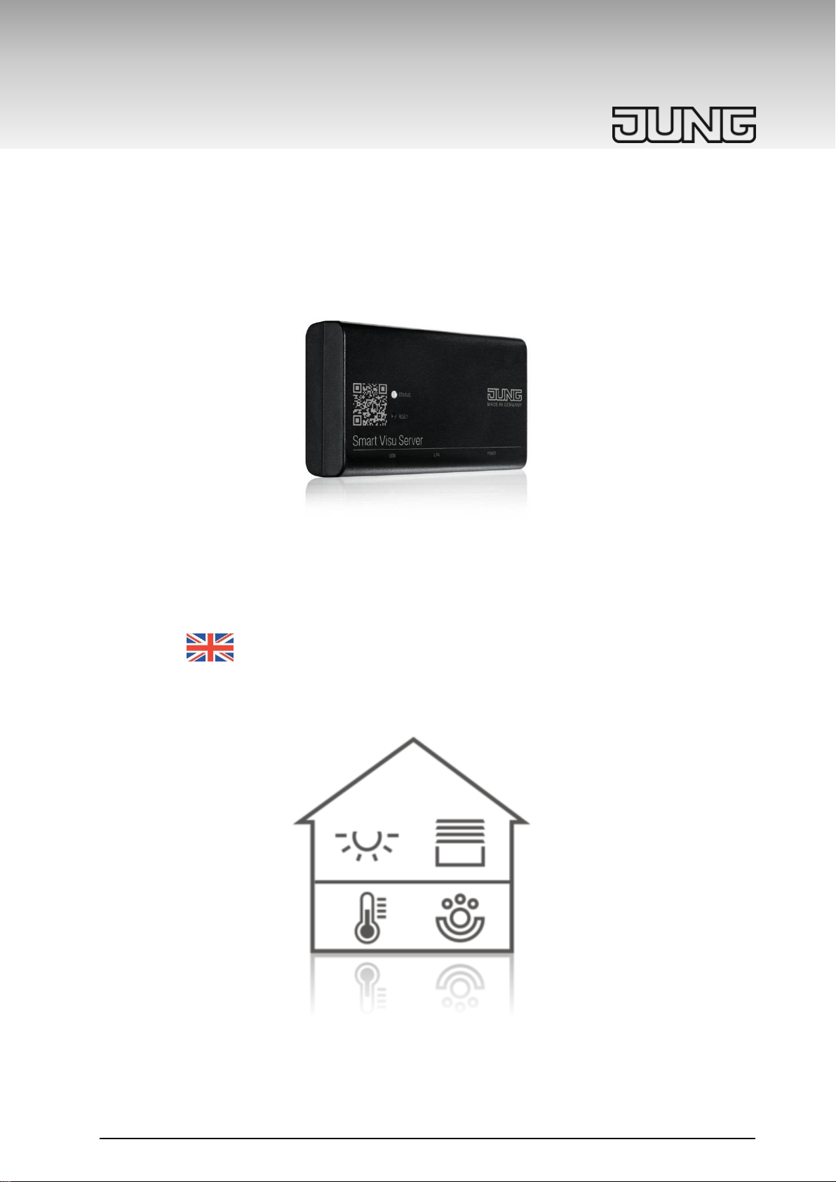
Smart Visu Server
Art-No.: SV-SERVER-01
SV-SERVER-INT
Product Documentation
Page 2

SV-SERVER-01 / SV-SERVER-INT 1 / 157
Product Documentation
Smart Visu Server
SV-SERVER-01
SV-SERVER-INT
ALBRECHT JUNG GMBH & CO. KG
Volmestraße 1
D-58579 Schalksmühle
Tel: +49 (0) 23 55/80 60
Fax: +49 (0) 23 55/80 61 89
[email protected]
https://www.jung.de/en/
Service Centre
Kupferstr. 17-19
44532 Lünen
Germany
Page 3

SV-SERVER-01 / SV-SERVER-INT 2 / 157
1 COMMISSIONING THE SMART VISU SERVER .............................................. 4
1.1 Correct use ........................................................................................................................ 4
1.2 Product characteristics .................................................................................................... 4
1.3 Scope of delivery .............................................................................................................. 5
1.4 Technical data ................................................................................................................... 5
1.5 Structure of the device, function ..................................................................................... 6
1.6 System information........................................................................................................... 7
1.7 Montage, commissioning ................................................................................................. 8
1.7.1 SV-Home – User interface ...................................................................................... 9
1.7.2 SV-Control – Project Design Interface .................................................................. 10
1.8 Warranty ........................................................................................................................... 11
2 SV-CONTROL ................................................................................................. 12
2.1 Project tab ........................................................................................................................ 12
2.1.1 Manage language ................................................................................................. 12
2.1.2 Start ....................................................................................................................... 12
2.1.3 Backing up a project ............................................................................................. 12
2.1.4 Restoring a project ................................................................................................ 13
2.1.5 Password protection ............................................................................................. 13
2.1.6 SV-Home ............................................................................................................... 15
2.1.7 Product Documentation ........................................................................................ 15
2.2 KNX ................................................................................................................................... 16
2.2.1 Defining the KNX-IP Gateway............................................................................... 16
2.2.2 Importing the KNX-OPC project file ...................................................................... 17
2.3 Hue.................................................................................................................................... 18
2.3.1 Defining the Hue-IP Gateway ............................................................................... 18
2.3.2 Importing Hue lamps ............................................................................................. 19
2.4 Area & Functions ............................................................................................................ 23
2.4.1 Creating a new area .............................................................................................. 24
2.4.2 Editing or deleting areas ....................................................................................... 25
2.4.3 Creating a new function ........................................................................................ 26
2.4.4 Configuring KNX functions .................................................................................... 28
2.4.5 Astro ...................................................................................................................... 86
2.4.6 Configuring Philips Hue functions ......................................................................... 89
2.4.7 Configuring websites / IP functions ....................................................................... 91
2.4.8 Configuring status logic functions ....................................................................... 101
2.4.9 Editing or deleting a function ............................................................................... 103
2.5 Action ............................................................................................................................. 104
2.5.1 Creating Actionsgroups ....................................................................................... 104
2.5.2 Creating an action ............................................................................................... 106
2.5.3 Editing or deleting an action ................................................................................ 110
2.5.4 Point in time overview of the actions .................................................................. 111
2.6 Configuration management ......................................................................................... 112
2.6.1 Network settings ................................................................................................. 113
2.6.2 Setting the system time and date ....................................................................... 114
2.6.3 Remote-Access ................................................................................................... 115
2.6.4 Server update ..................................................................................................... 121
3 SV-HOME ...................................................................................................... 122
3.1 SV-Home settings ......................................................................................................... 123
3.1.1 Language ............................................................................................................ 124
3.1.2 Columns setting .................................................................................................. 124
3.1.3 Design ................................................................................................................. 125
3.1.4 Start page............................................................................................................ 125
3.1.5 Font size .............................................................................................................. 126
3.1.6 Presentation labels ............................................................................................. 126
3.2 SV-Server App for Android .......................................................................................... 127
3.3 SV-Server App for iOS .................................................................................................. 128
4 UPDATE OF THE SMART VISU SERVER .................................................... 129
4.1 Reading out the software version ............................................................................... 129
Page 4

SV-SERVER-01 / SV-SERVER-INT 3 / 157
4.2 Performing a system update ........................................................................................ 129
5 APPLICATIONS EXAMPLES ........................................................................ 130
6 MAINTAINING THE SMART VISU SERVER ................................................ 131
7 APPENDIX ..................................................................................................... 131
7.1 Accessories ................................................................................................................... 131
8 COPYRIGHT .................................................................................................. 132
8.1 Open Source Lizenzen ................................................................................................. 133
8.1.1 GNU GENERAL PUBLIC LICENSE Version 2 (GPL v2) ................................... 133
8.1.2 GNU GENERAL PUBLIC LICENSE Version 3 (GPL v3) ................................... 139
8.1.3 GNU LESSER GENERAL PUBLIC LICENSE Version 3 (LGPL) ....................... 150
8.1.4 Eclipse Public License - v 1.0 (EPL) ................................................................... 153
Page 5
SV-SERVER-01 / SV-SERVER-INT 4 / 157
WARNING
Failure to comply with these instructions may result in damage to the
device, fire or other hazards. These instructions are a component part
of the product and must remain with the end customer. Electrical
equipment must only be installed and mounted by qualified electricians.
This product is only intended for use in dry rooms.
1 Commissioning the Smart Visu Server
Safety instructions
1.1 Correct use
- Visualisation and operation of KNX systems via terminals with HTML5-compatible
browsers or App (iOS, Android), e.g. smartphone, tablet, laptop, PC etc.
- Visualisation and operation of Philips Hue systems
- Operation in local IP networks, which support DHCP (Dynamic Host Configuration
Protocol), or with fixed IP address (IPv4)
- Interior operation
1.2 Product characteristics
- Web visualisation of the KNX system for status display and operation (SV-Home)
- Access to the SV-Home web visualization with max. 10 different clients (recommended)
- Integrated web-based start-up tool (SV-Control)
- Simple creation of a preconfigured operating desktop, optimised for applications at
home and in small commercial buildings
- Graphical operating elements, selection of icons from supplied libraries
- Import of group addresses (three-level) via OPC import (ETS3, ETS4, ETS5)
- Manual input of group addresses possible
- 24 areas
- 240 dynamic functions (max. 1200 datapoints)
o Switch
o Dimming
o Motor
o Climate
o Status / Value
o Website
o Webcam
o State logic
- 250 configurable actions (max. 16 functions per action)
o User-defined
o Point in time
o Event
- Connection to the KNX-BUS via KNX-IP router or KNX-IP interface
- Integration of Philips Hue systems in the KNX system
- Connection to Philips Hue via the Philips Hue Bridge
- Updateable and upgradeable
Page 6
SV-SERVER-01 / SV-SERVER-INT 5 / 157
Rated voltage:
DC 12 V SELV
Power consumption:
Typ. 3 W, max. 7 W
Ambient temperature:
–5 ... +45 °C
Storage/transport temperature:
–25 ... +70 °C
LAN:
RJ45 socket (10/100 Mbit/s Fast Ethernet) CAT5
USB:
USB 2.0 Host
Dimensions:
124 x 72 x 31 mm (without retaining unit)
124 x 92 x 40 mm (with retaining unit)
Power supply unit with plug:
Primary voltage:
AC 100 ... 240 V ~
Mains frequency:
50 / 60 Hz
Rated current:
Max. 1 A
Secondary voltage:
DC 12 V SELV
Protection class:
II
Length of connecting cable:
1.5 m
Plug contact:
SV-SERVER: EU
SV-SERVER-INT: BS,EU,CN
CAUTION
This device contains a battery (CR1632, 0.4 Wh) to back up the saved
data. Do not dispose of discharged batteries with domestic waste.
During transport, comply with the special regulations of the ADR and
IATA.
1.3 Scope of delivery
- Smart Visu Server including software
- Retaining bracket for wall or support rail mounting
- Operating instructions
- Power supply unit with plug
o SV-SERVER: EU power supply unit (Euro plug)
o SV-SERVER-01: Power supply unit, including adapter for BS (United
Kingdom), EU (Euro plug) and CN (China)
o SV-SERVER-INT: Power supply unit, including adapter for BS (United
Kingdom), EU (Euro plug) and CN (China)
Legal information
Philips and Hue are registered trademarks of Koninklijke Philips Electronics NV.
This product contains Open Source software components, which are subject to the
conditions of Copyright and/or the license agreements of third parties. The license
information is located on the Smart Visu Server.
1.4 Technical data
Page 7
SV-SERVER-01 / SV-SERVER-INT 6 / 157
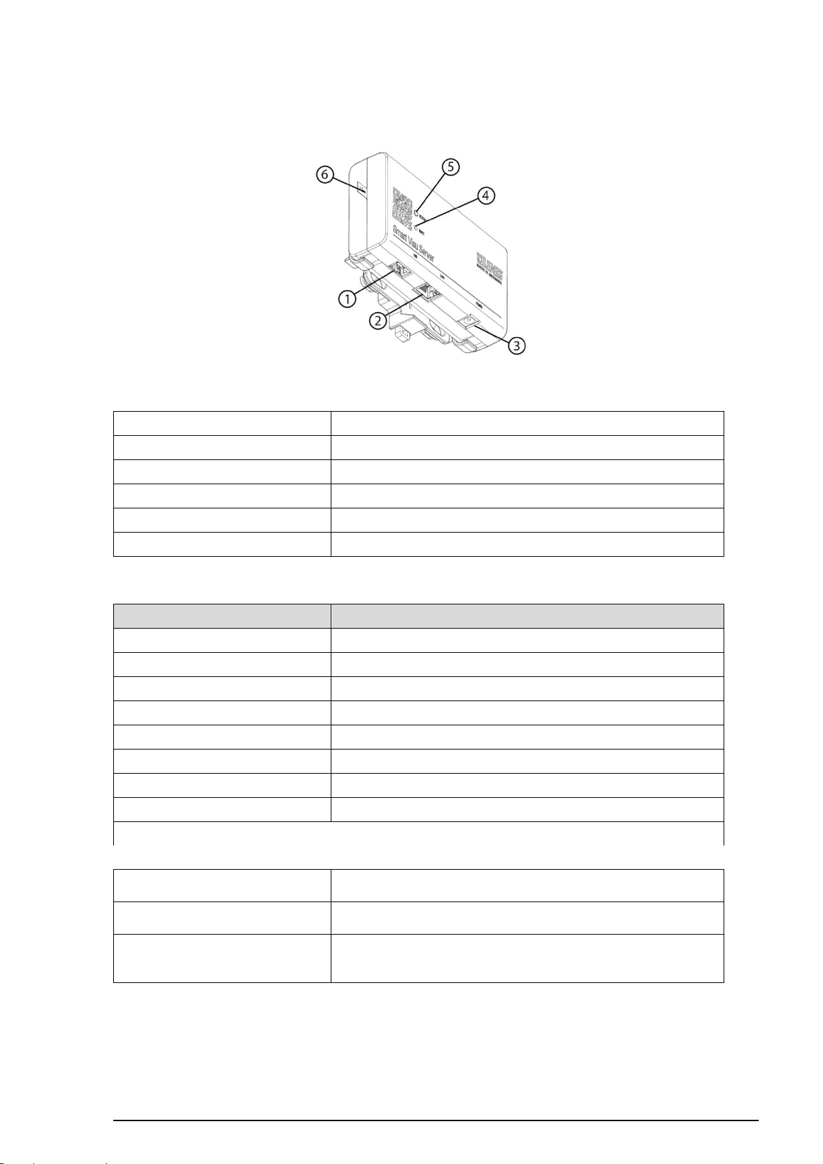
(1) USB interface
For software updates and data backup
(2) Ethernet interface
For connection to the local network
(3) Power supply
Only the power supply unit from the scope of delivery
(4) Reset button
Reset and update
(5) Status LED
Displays the current status of the server
(6) Discharge protection
Remove for operation
The Status LED (5) displays the various operating statuses.
Colour of the Status LED
Function
Flashing yellow
Server booting
Flashing red
Error pending, server stopping
Continuous dimly yellow
Server and network booting
Continuous brightly yellow
Server gets IP-adress
Continuous blue
Server ready, DHCP active
Continuous green
Server ready, static network address
Flashing blue/magenta
Update operation, DHCP active
Flashing green/magenta
Update operation, static network address
The Reset button (4) triggers a reset or an update.
Reset network settings, DHCP
operation active
Press the button ≥ 5 seconds, LED flashes yellow, press the
button again briefly
Factory reset
Press the button for 20 seconds, LED flashes red, press the
button again briefly
Initialise update operation
Press the button briefly 5x
- LED turns magenta: No update available - LED flashes
magenta: Update operation
1.5 Structure of the device, function
Figure 1: Structure of the Smart Visu Server
Page 8
SV-SERVER-01 / SV-SERVER-INT 7 / 157
1.6 System information
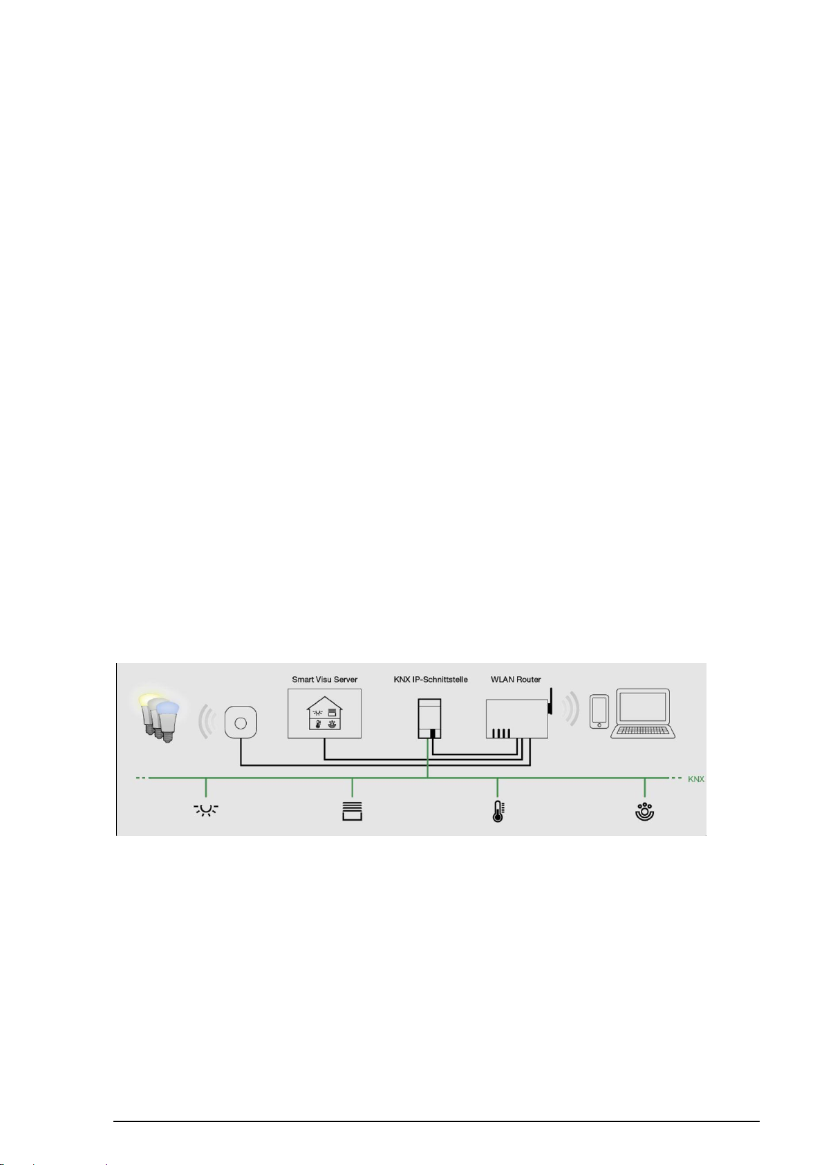
The Smart Visu Server is used to visualise and operate a KNX system connected to the
same network via a smartphone, tablet, laptop or PC and to control Philips Hue systems
(SV-Home). A local network is required for it to function.
The connection to the KNX is made via the KNX IP interface. The connection to the Philips
Hue system is made via the Philips Hue Bridge.
Start-up takes place via the web-based interface (SV-Control). The technical documentation
is also available here.
The server organises KNX functions and Philips Hue operation into areas, functions and
actions.
Areas: An area indicates an assignment, e.g. to a room. Up to 24 areas are
possible.
Function: A function corresponds to, for example, a KNX function, thus possibly
comprising multiple group addresses, e.g. switching channel with
feedback. A function could also be the link to a Philips Hue lamp. Up to
240 functions can be created with up to 1200 datapoints. Each function
can be assigned to one or more areas.
Action: An action is a grouping of one or more functions. Actions can be triggered
by events, by time or via user-defined controls. Up to 250 actions are
possible.
Action group: An action group is used to group individual actions. Up to 25 Action groups
can be activated or deactivated as required.
KNX projects can be imported from the OPC export (3-level group address) of ETS3, ETS4
or ETS5 or be created manually. (see chapter 2.2.2)
Page 9
SV-SERVER-01 / SV-SERVER-INT 8 / 157
1
2
1.7 Montage, commissioning
Mounting takes place using the supplied retaining unit on the wall or on a support rail
according to DIN EN 60715. The server is snapped onto the retaining unit.
A current HTML5-capable browser (input device) or the corresponding iOS / Android App is
required for access to SV-Home and SV-Control. The Smart Visu Server, KNX-IP-Gateway,
network router (DHCP active) and input device must all be a part of the same network.
During start-up, the Smart Visu Server expects the assignment of an IP address via DHCP.
Remove the discharge protection from the server. Connect the server to the network and
the power supply unit to the server. After the mains plug has been connected, the server will
boot. As soon as the Status LED turns blue, the server is ready for operation. In the address
line of the Internet browser, enter:
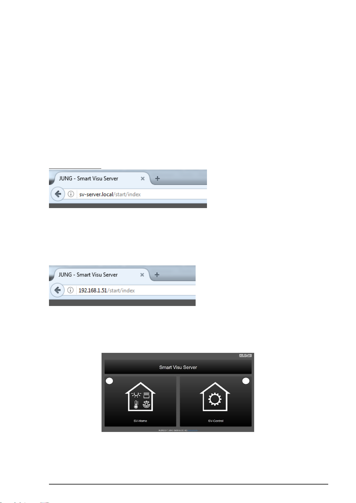
http://sv-server.local
This opens the homepage of the server.
If your network doesn’t support it, then determine the IP address of the server in the router
manually. Enter the determined address, e.g. 192.168.1.51, in the address line of your
Internet browser, e.g.:
This opens the homepage of the server. On the homepage, for further actions, the webbased software tool "SV-Home" (1) can be used for the visualisation and operation of the
Smart Visu Server, as can "SV-Control" (2) for the configuration and commissioning of the
same.
Figure 2: Homepage of the Smart Visu Server
Page 10
SV-SERVER-01 / SV-SERVER-INT 9 / 157
Areas (1)
Functions / actions (2)
1
1.7.1 SV-Home – User interface
The SV-Home is the integrated web interface of the Smart Visu Server for the visualisation,
status display and operation of the KNX system and the Philips Hue system. The SV-Home
is generated automatically from the configuration set up in SV-Control.
A current HTML5-compatible browser (input device) is required for access to SV-Home.
Recommended is the access of max. 10 different clients on the SV-Home web interface.
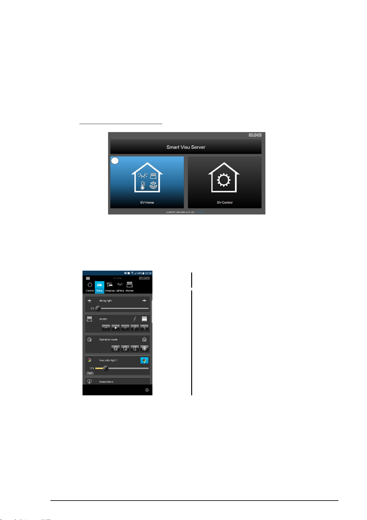
When the server is opened, the SV-Home visualisation can be started by selecting the left
button or http://IP-address/SV-Home/ (1).
Figure 3: Opening SV-Home
The top pane (1) displays the areas created in SV-Control with the selected icon and name.
It is also possible to display the defined area of the actions. Selecting an area displays the
assigned functions and actions (2) beneath.
Figure 4: Structure of the SV-Home visualisation
Depending on the created function type, these functions visualise their status (e.g. the
current room temperature) or offer a chance to influence it (e.g. move a Venetian blind or
dim a Philips Hue lamp).
Page 11
SV-SERVER-01 / SV-SERVER-INT 10 / 157
1
1
1.7.2 SV-Control – Project Design Interface
This subchapter is intended to help you get to know the structure of the project design
interface. The following chapter describe the functions and exact procedure for project
design in more detail.
SV-Control is the integrated web-based commissioning tool of the Smart Visu Server. In
addition, the system configuration can be performed here.
A current HTML5-compatible browser (input device) or the corresponding iOS / Android
App is required for access to SV-Control.
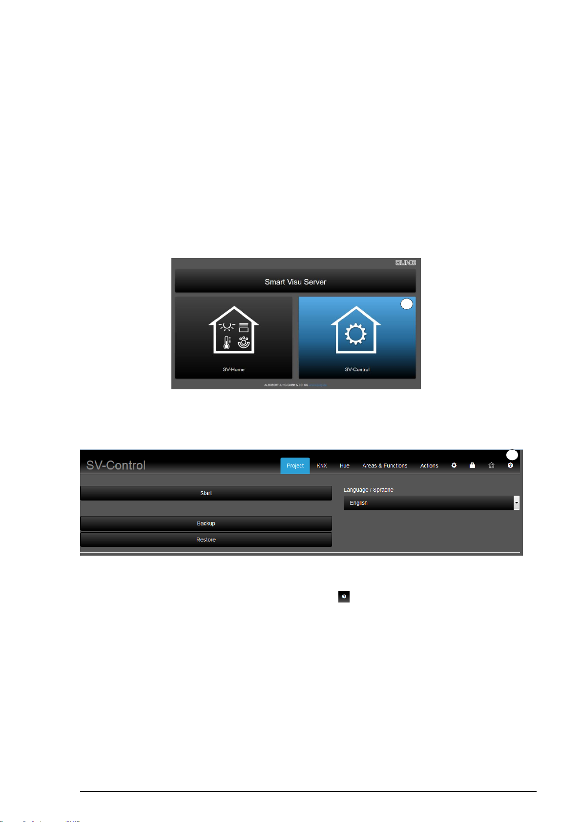
After calling up SV startpage, the SV control can be started by selecting the right-hand
button (1).
Figure 5: Opening SV-Control
The homepage of SV-Control then opens.
Figure 6: Start page of SV-Control
The product documentation can be opened using the " " (1) button.
Page 12

SV-SERVER-01 / SV-SERVER-INT 11 / 157
1.8 Warranty
- Warranty is offered according to the statutory provisions via specialist dealers.
- The CE symbol is a free trade symbol, intended solely for the authorities and does not
carry any guarantee of properties.
Page 13
SV-SERVER-01 / SV-SERVER-INT 12 / 157
- German
- English
- French
- Dutch
- Italian
- Spainish
- Portuguese
- Russian
- Estonia
- Lithuanian
- Latvian
- Polnish
- Ukrainian
- Korean
- chinese
5 6 3 1 4
2
2 SV-Control
This chapter describes the configuration and commissioning of the Smart Visu Server using
SV-Control in detail.
2.1 Project tab
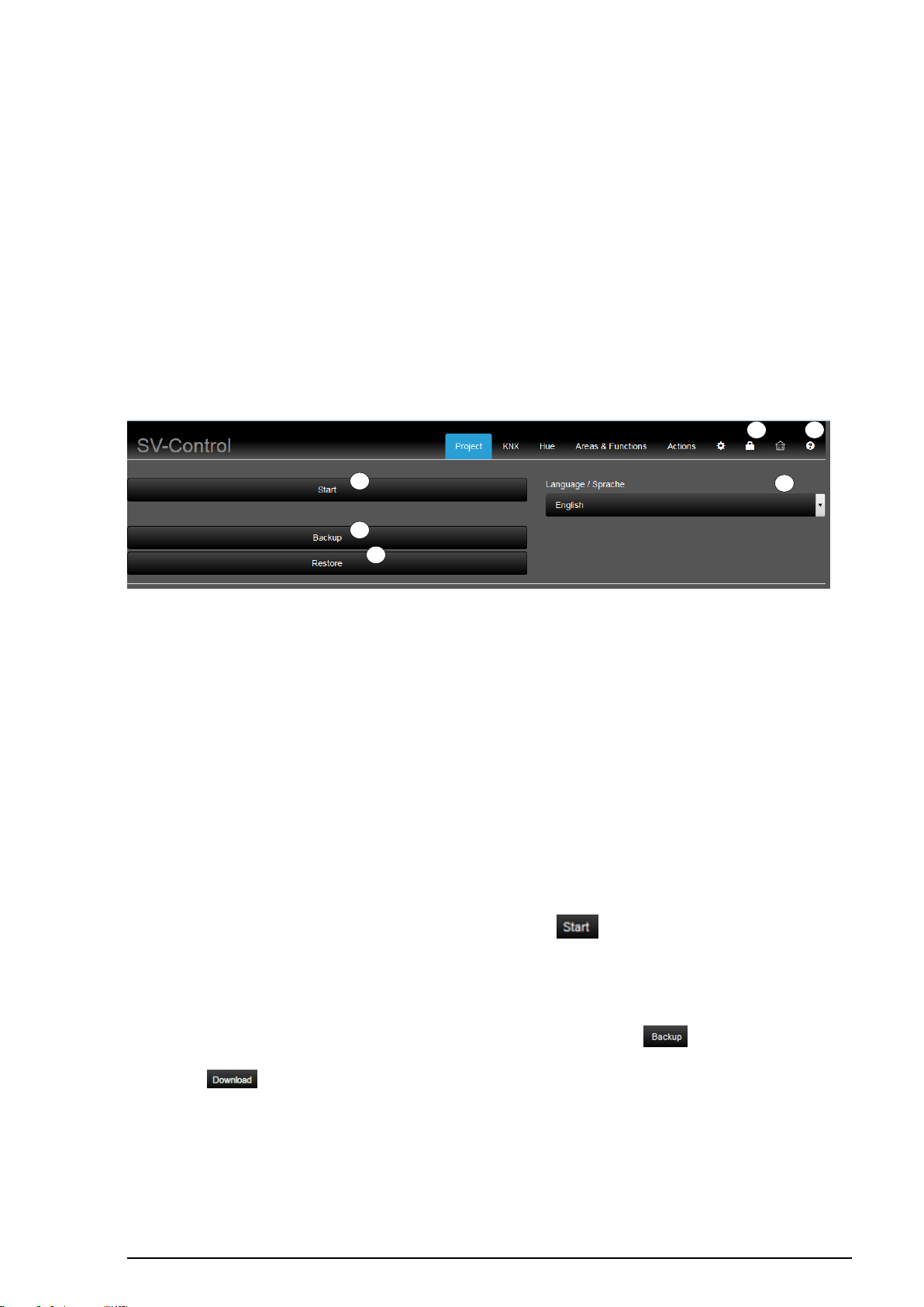
The "Project" tab serves as the homepage of SV-Control. Here, it is possible to set the
required language (1), start project design (2), back up the overall project (3) or restore a
previously backed up project (4).
After project design has been completed, access to the project design functions can be
protected by assigning a password (5).
In addition, the product documentation (6) is stored in SV-Control in German and English.
Figure 7: SV-Control, Project tab
2.1.1 Manage language
The desired project design language (1) can be specified in the "Project" tab. It is possible
to change over the language settings during commissioning or at a later time.
The following languages are available in the selection menu (1):
2.1.2 Start
Begin project design of the Smart Visu Server using the " " button (2).
2.1.3 Backing up a project
The backup of the current project design can be triggered using the " " button (3). This
operation can take a moment to complete. Then, the project design can be downloaded
using the " " button (3).
Page 14
SV-SERVER-01 / SV-SERVER-INT 13 / 157
INFORMATION
The Smart Visu Server can only manage one project. If a project is
downloaded using the "Restore" button, any existing project will be
deleted.
1
2.1.4 Restoring a project
A previous project state can be restored using the " " button (4). This operation can
take a couple of minutes to complete.
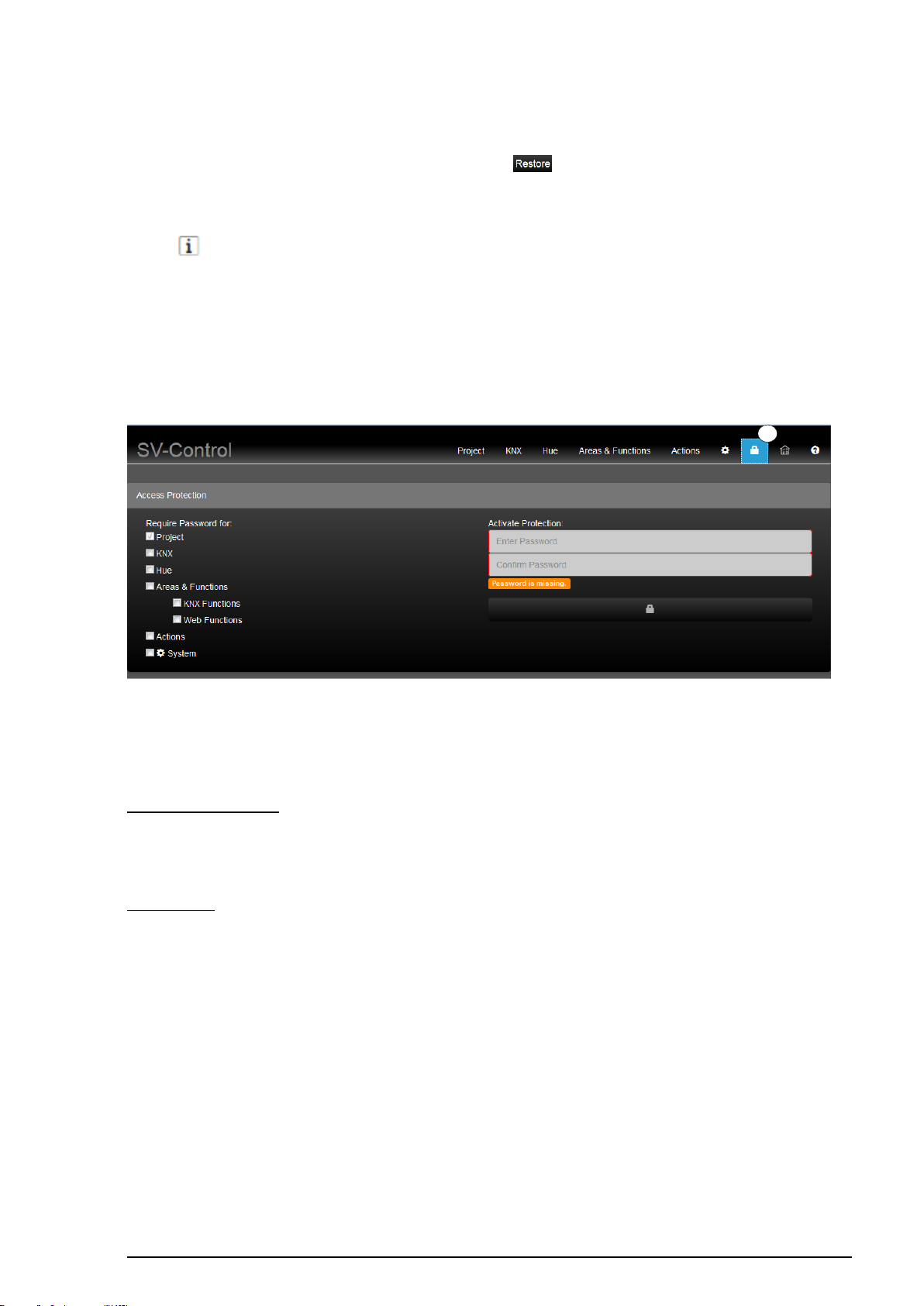
2.1.5 Password protection
After project design has been completed, access to the elementary project design
functions can be protected with a password (1).
Figure 8: SV-Control Access Protection
The SV-Control differentiates between complete / restricted access "Administrator" and
"User".
Administrator rights:
- Complete access to all tabs
User rights:
User access rights are determined by the check boxes of the respective tab / category.
When a password is set the user has no access within the “Project” tab.
Additional check boxes:
Page 15
SV-SERVER-01 / SV-SERVER-INT 14 / 157
KNX
- No access within “KNX” tab
Hue
- No access within “Hue” tab
Areas & Functions
- No access within “Areas & Functions” tab
Exclusively
KNX functions
- Right to create, change and delete areas
- Right to add or delete “Hue functions” from areas
- No right to delete “KNX functions” completely or to edit group
addresses of KNX functions.
- Only names and icons of KNX functions can be edited and they
can be assigned to additional areas or deleted from assigned
areas.
Web functions
- Right to create, change and delete areas
- Right to add or delete “Hue functions” from areas
- No right to delete “Web functions” or to edit the URL of Web
functions
- Only names and icons of Web functions can be edited and they
can be assigned to additional areas or deleted from assigned
areas.
Actions
- No access within “Actions” tab
System
- No access within “System” tab
Additional tabs
- Limited access within “Access protection” tab
- Full access within “SV-Home” tab
- Full access within “Help” tab
Administrator active:
The "User" profile is activated after optional
assignment of a password.
User active:
The "Administrator" profile is activated
after any set password is input.
1
2
1
2
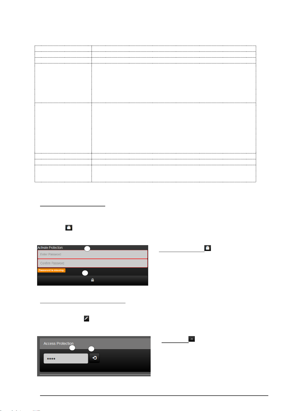
Activating the "User" profile
It is possible to specify an Administrator password using the optional assignment of a
password in the input fields (1). To activate the "User" profile and apply the password,
press the " " button (2).
Activating the "Administrator" profile
To activate the "Administrator" profile, enter the administrator password in the input field
(1) and press the " " button (2).
Page 16
SV-SERVER-01 / SV-SERVER-INT 15 / 157
1
2
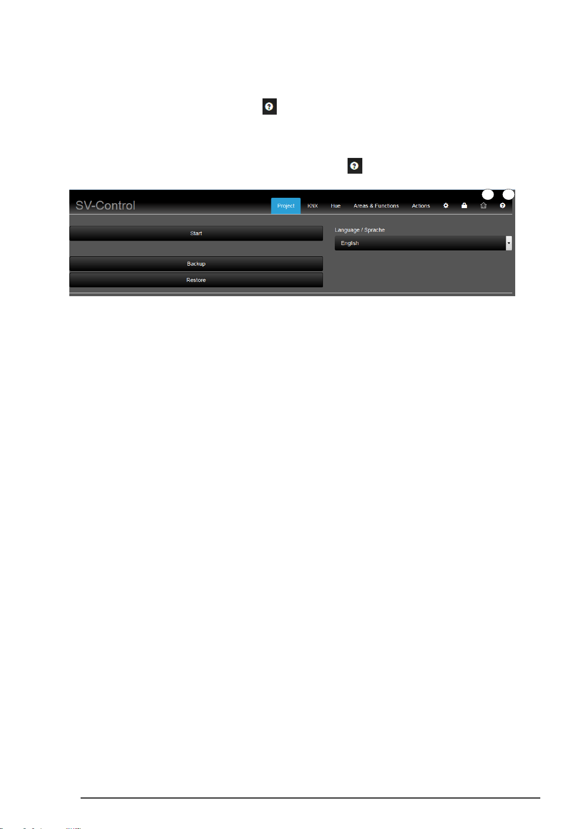
2.1.6 SV-Home
SV Home can be called up using the " " button (1) in Figure 9.
2.1.7 Product Documentation
The product documentation can be called up using the " " button (1) in Figure 9.
Figure 9: SV-Control Access Protection
Page 17
SV-SERVER-01 / SV-SERVER-INT 16 / 157
4 1 3
2
2.2 KNX
The "KNX" tab is used to define the KNX-IP Gateway and to import the KNX group
addresses using the OPC project file.
2.2.1 Defining the KNX-IP Gateway
To be able to use the KNX functionality of the Smart Visu Server, a connection to the KNX
system via a KNX-IP data interface is required, which can be reached from the Smart Visu
Server via the IP network.
We recommend using one of the following KNX-IP data interfaces:
- Jung: KNX IP interface Art. no.: IPS 200 REG
- Jung: KNX IP router Art. no.: IPR 200 REG
The Smart Visu Server must be informed of the current IP address of the KNX-IP data
interface. The simplest way to do this is to determine them from the ETS configuration of the
device (static IP address active) or from the network router (DHCP active). Enter the
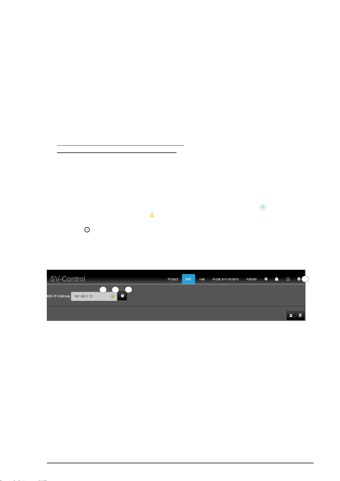
determined IP address of the KNX-IP data interface in the "KNX-IP Gateway" field (2).
Immediately on entry, the connection to the KNX-IP data interface is checked. If the
connection is successful, the test is visualized by a green checkmark ( ) or, if it is
unsuccessful, by an orange triangle ( ) at the end of the input line (3).
The button ( ) provides more information about your KNX-IP data interface and the
connection (4).
The "KNX" tab can be operated fully for both profiles (Administrator/User).
Figure 10: Defining the KNX-IP Gateway
If the connection is faulty, please check the following settings:
- The KNX-IP data interface is switched on and connected to the IP network
- The KNX-IP data interface possess IP address assignment valid for your system
o IP address
o Subnet mask
o Routing Multicast address
- The KNX-IP data interface is set to Port 3671
Page 18
SV-SERVER-01 / SV-SERVER-INT 17 / 157
1 3 4
2
2.2.2 Importing the KNX-OPC project file
SV-Control offers the option of importing ETS projects in the form of OPC project files. OPC
project files can be generated from the ETS3 (File Data Exchange), ETS4 (Tools
Export OPC) and ETS5 (Export project file type - OPC) and contain all the group
addresses, group names, group descriptions and data types created in your project.
The OPC project file helps you to connect the KNX functions of your Smart Visu Server to
the appropriate group addresses of the ETS project quickly and simply.
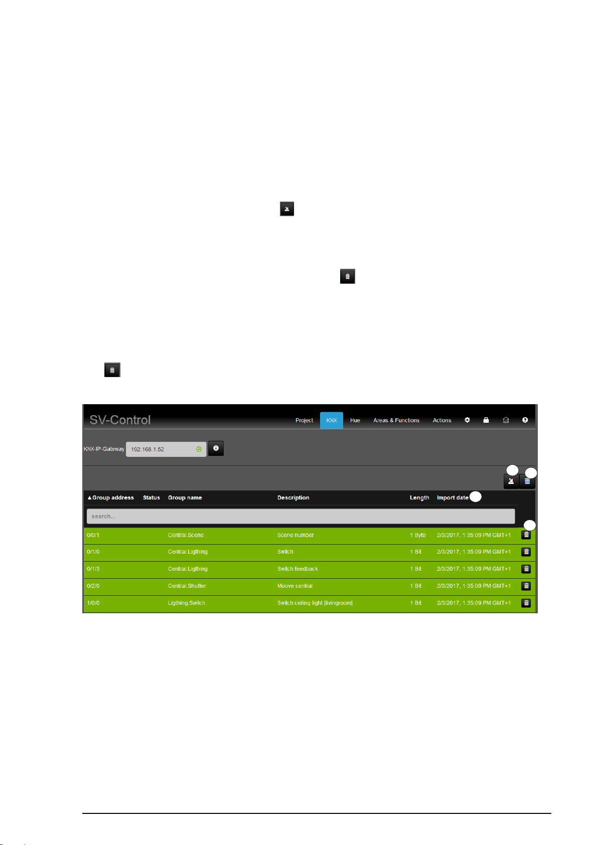
To import the OPC project file, click the " " button (1). You will then be asked to select the
file and upload it to the Smart Visu Server. After uploading, all the imported group addresses
are listed below the Import function, together with the group name, the group description
and the data type length.
You can delete the entire OPC project file using the " " button (2).
You now have the option of actively filtering in the input field (3) (e.g. by name or group
addresses) or to display the sorted list by clicking the appropriate column header (group
address, status, etc.).
Individual group addresses which are not required can be deleted from the list by clicking
the " " (4) button in the appropriate line.
Figure 11: Importing KNX group addresses
Page 19
SV-SERVER-01 / SV-SERVER-INT 18 / 157
2 3 1
2.3 Hue
The "Hue" tab is used for the definition of the Philips Hue Bridge and to import previously
integrated Hue devices and other ZigBee Light Link components.
The "Hue" tab can be operated fully for both profiles (Administrator/User).
2.3.1 Defining the Hue-IP Gateway
The Smart Visu Server supports the integration, visualisation and operation of the Philips
Hue System.
To be able to use the hue functionality of the Smart Visu Server, a Philips Hue Bridge is
required, which can be reached from the Smart Visu Server via the IP network. In addition,
the Philips Hue System must have been commissioned. Please refer to the manufacturer's
documentation for the appropriate steps.
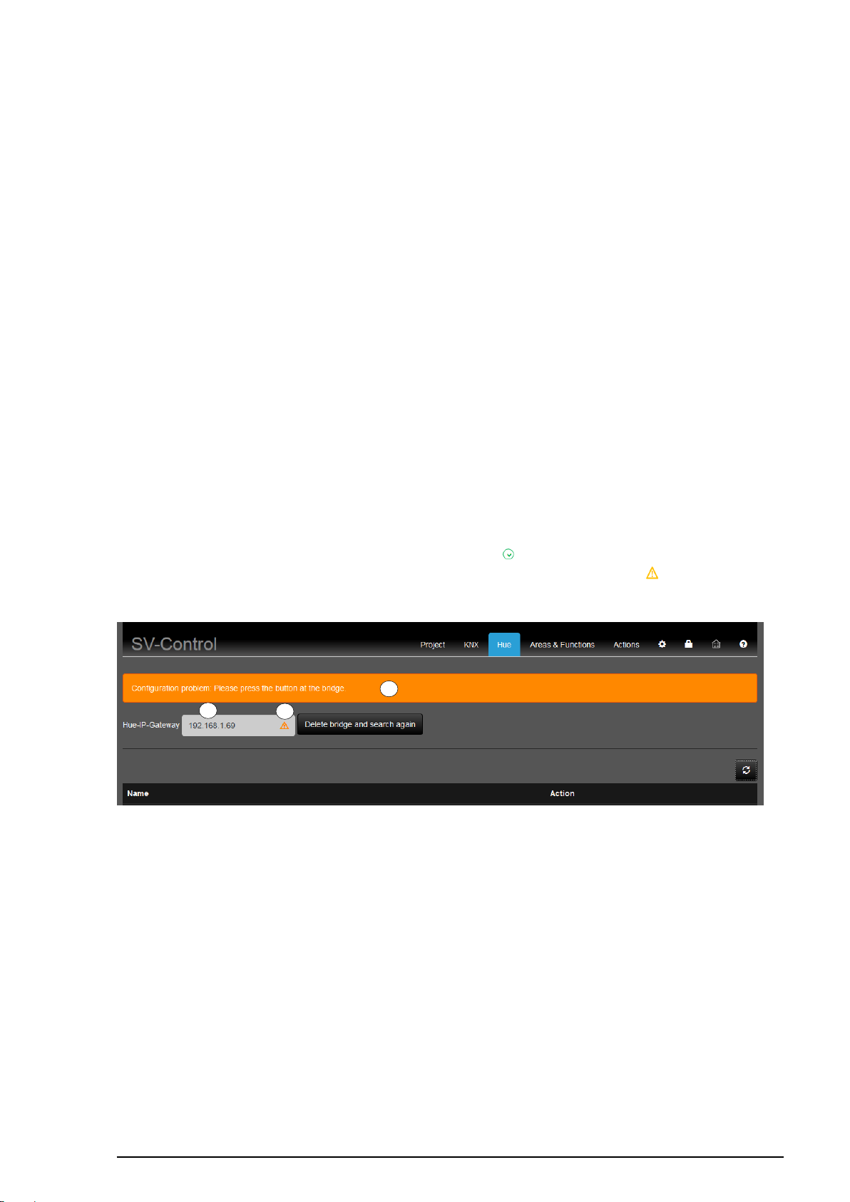
The IP address of the Philips Hue Bridge is automatically detected by the Smart Visu Server
and displayed in the "Hue-IP-Gateway" (1) text box.
To couple the Bridge with the Smart Visu Server, press the Pairing button of the Bridge for
authentication (2).
Successful pairing is visualised by a green checkmark ( ) at the end of the input line (3). A
faulty connection or unsuccessful pairing is visualised by an orange triangle ( ) in the same
location.
Figure 12: Defining the Philips Hue Bridge
Page 20
SV-SERVER-01 / SV-SERVER-INT 19 / 157
1 3 2
2.3.2 Importing Hue lamps
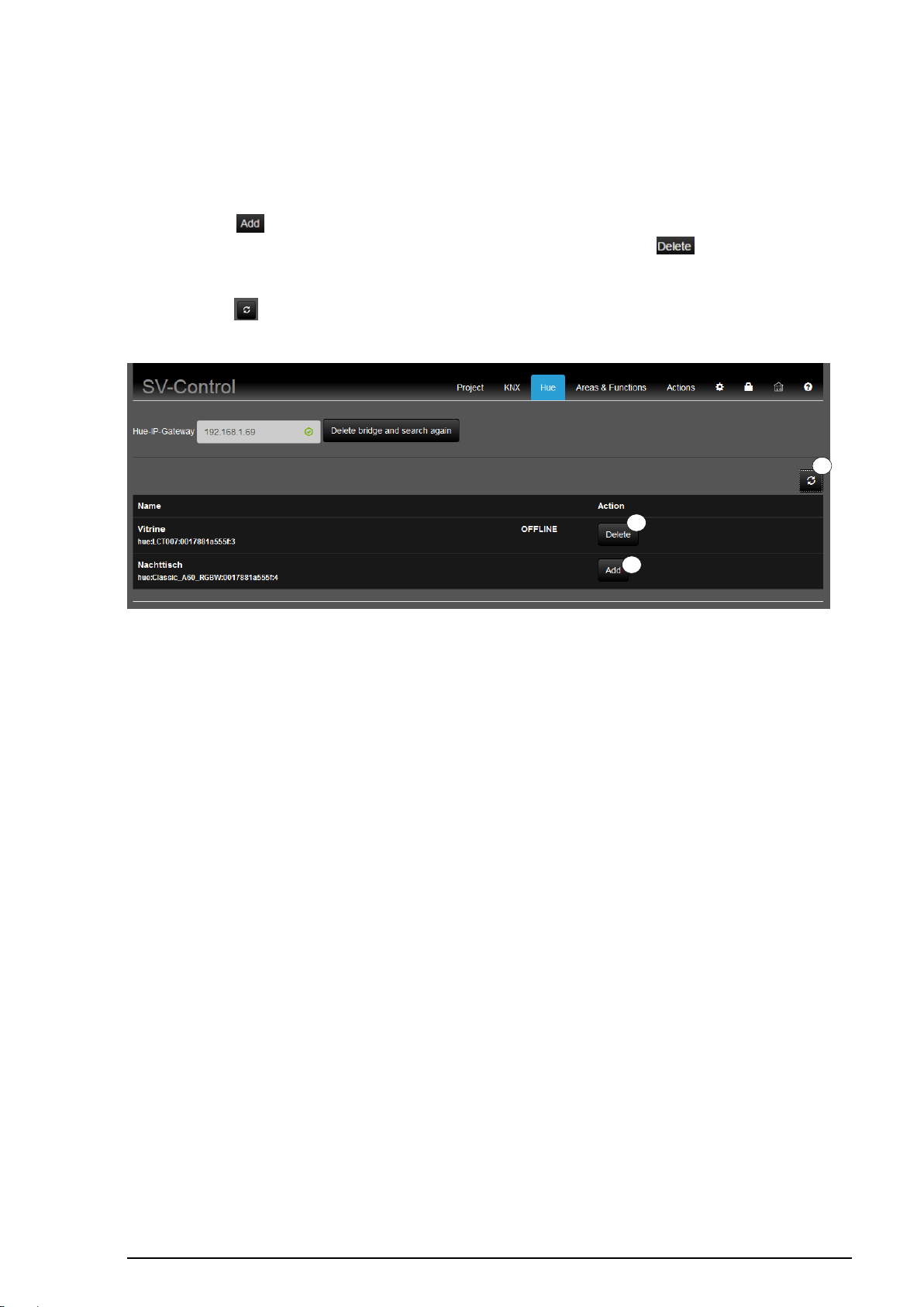
The lamps configured in the Hue system are then listed beneath with their name and the
current status. Only those lamps can be listed that are configured in the bridge.
Pressing the " " button (1) allow the selected lamps to be added as the Hue function.
Previously added lamps can be removed again using the same button " " (2). If you wish
to add unlisted lamps, then they must be first configured in the Hue Bridge.
Pressing the " " button (3) reads out the Bridge configuration again. Newly-added lamps
are then added automatically to the list and can be added as a function, as described above.
Figure 13: Integrating Philips Hue lamps
Page 21
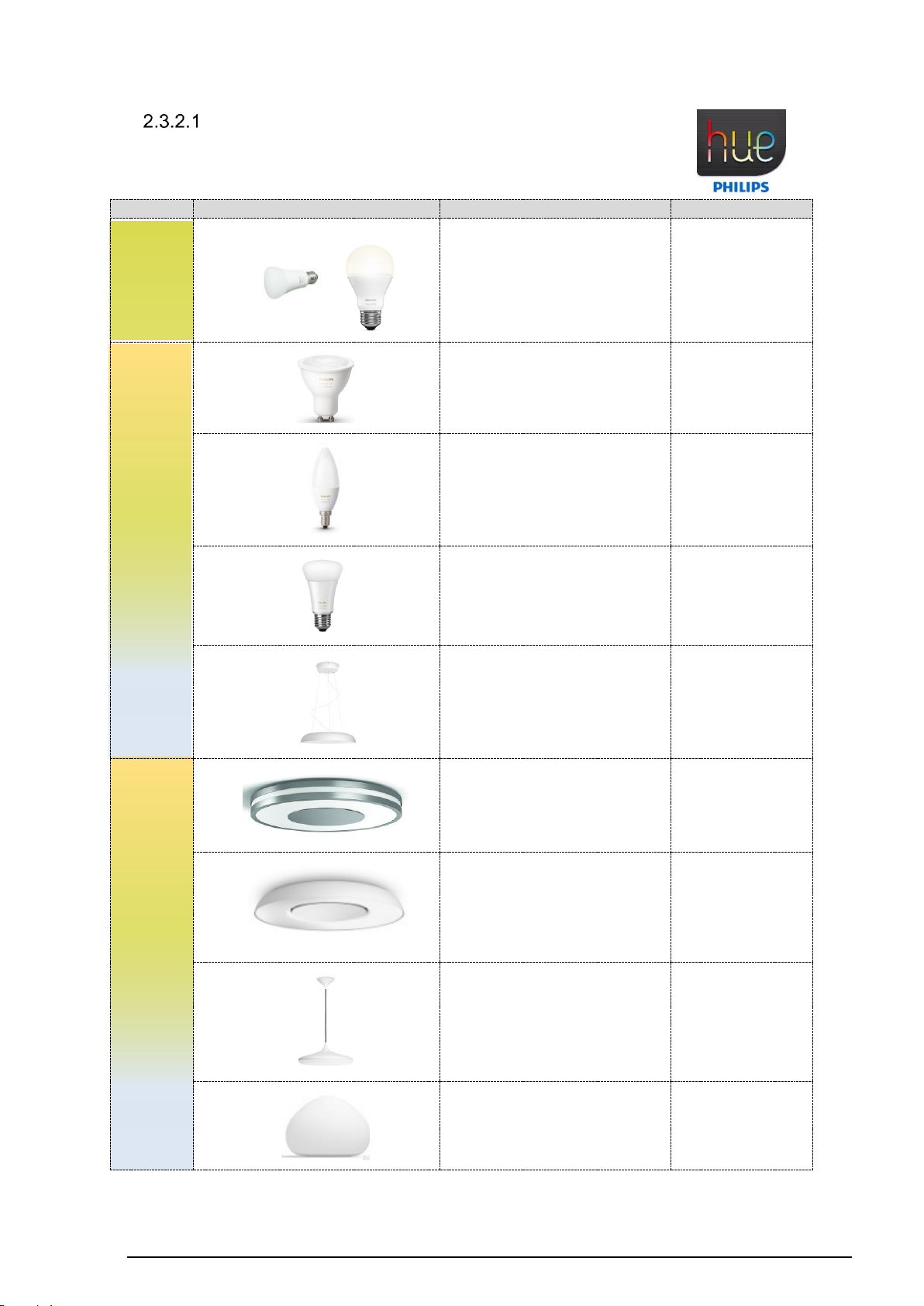
SV-SERVER-01 / SV-SERVER-INT 20 / 157
Group
Figure
Name
compatibility
WHITE
Hue White
WW
✔
TUNEABLE WHITE
Hue GU10
TW
✔
Hue White Ambiance E14
TW
✔
Hue White Ambiance E27
TW
✔
Hue white ambiance
Flexstrip
TW
✔
TUNEABLE WHITE
Hue White Ambience Being
TW
✔
Hue white ambiance
Flexstrip
TW
✔
Hue White Ambiance Cher
✔
Hue white ambiance wellner
TW
✔
ZigBee – tested devices
Page 22
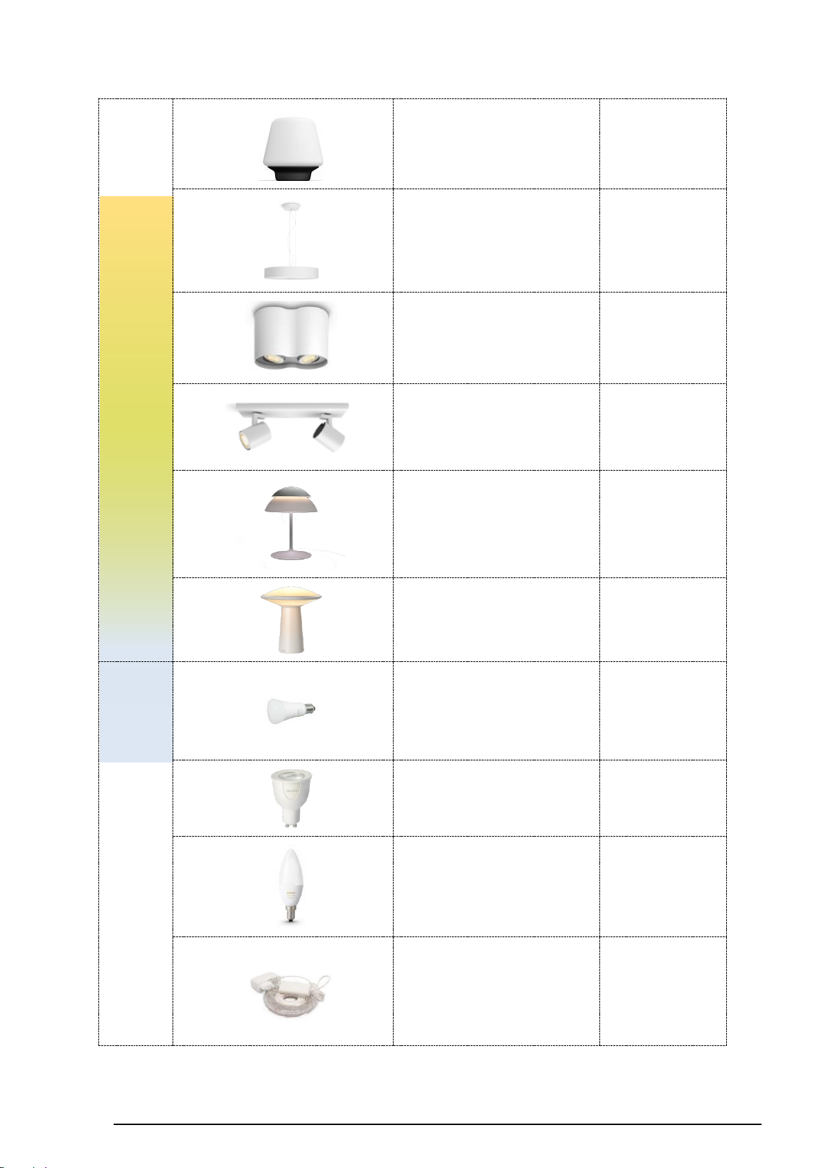
SV-SERVER-01 / SV-SERVER-INT 21 / 157
TUNEABLE WHITE
Hue white ambiance
wellness
TW
✔
Hue white ambiance
Flexstrip
TW
✔
Hue White Ambiance Spot
Pillar
TW
✔
Hue White Ambiance – Spot
Runner GU10
TW
✔
Hue Beyond
TW
✔
Hue Phoenix
TW
✔
RGBW
Hue E27
RGBW
✔
Hue GU10
RGBW
✔
Hue White and Color
Ambiance
RGBW
✔
Hue LightStrip
RGBW
✔
Page 23
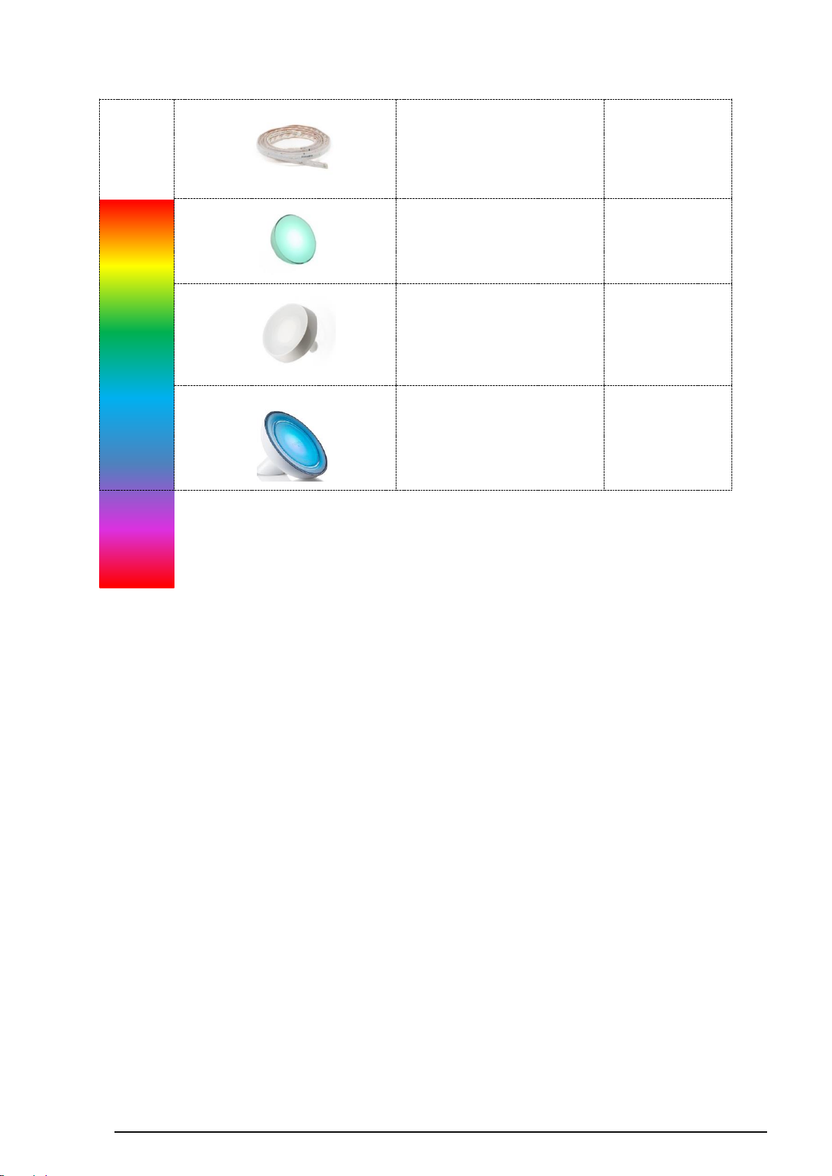
SV-SERVER-01 / SV-SERVER-INT 22 / 157
RGBW
Hue LightStrip Plus
RGBW
✔
Hue Go
RGBW
✔
Hue Iris
RGBW
(✔)
Attention! Must
be Friends of
Hue certified!
Hue Bloom
RGBW
(✔)
Attention! Must
be Friends of
Hue certified!
Page 24
SV-SERVER-01 / SV-SERVER-INT 23 / 157
Access
User
Areas & Functions
KNX
Web
Administrator
Create new areas
Edit the names of the areas
Edit the icons of the areas
Edit the sequence of functions within the areas
Delete existing areas
Create new KNX functions
Create new Hue functions
Create new web functions
Edit the names of the KNX functions
Edit the names of the Hue functions
Edit the names of the web functions
Edit the icons of the KNX functions
Edit the icons of the Hue functions
Edit the icons of the web functions
Edit the group address of the KNX functions
Edit the URL of the web functions
Edit the update rate of the web functions
Edit the resolution of the web functions
Assign new existing KNX functions to new areas
Assign new existing Hue functions to new areas
Assign new existing web functions to new areas
Remove existing KNX functions from new areas
Remove existing Hue functions from new areas
Remove existing web functions from new areas
Permanently delete existing KNX functions
Permanently delete existing Hue KNX functions
Permanently delete existing web KNX functions
2.4 Area & Functions
An area is a group of functions and actions for visualisation in SV-Home under an individual
area name. To improve recognition, an icon can be added to each of the up to 24 areas.
Areas allow you to group the up to 240 functions and 250 actions as you require, e.g.
spatially and/or by unit. Functions can be assigned to multiple areas simultaneously.
The access rights within the “Area & Functions” tab are limited for the “User” profile.
Overview of the access rights with activated check boxes:
Table 1: Access rights of the Administrator and the User
Page 25
SV-SERVER-01 / SV-SERVER-INT 24 / 157
2 1 3
6 5 4 7 8
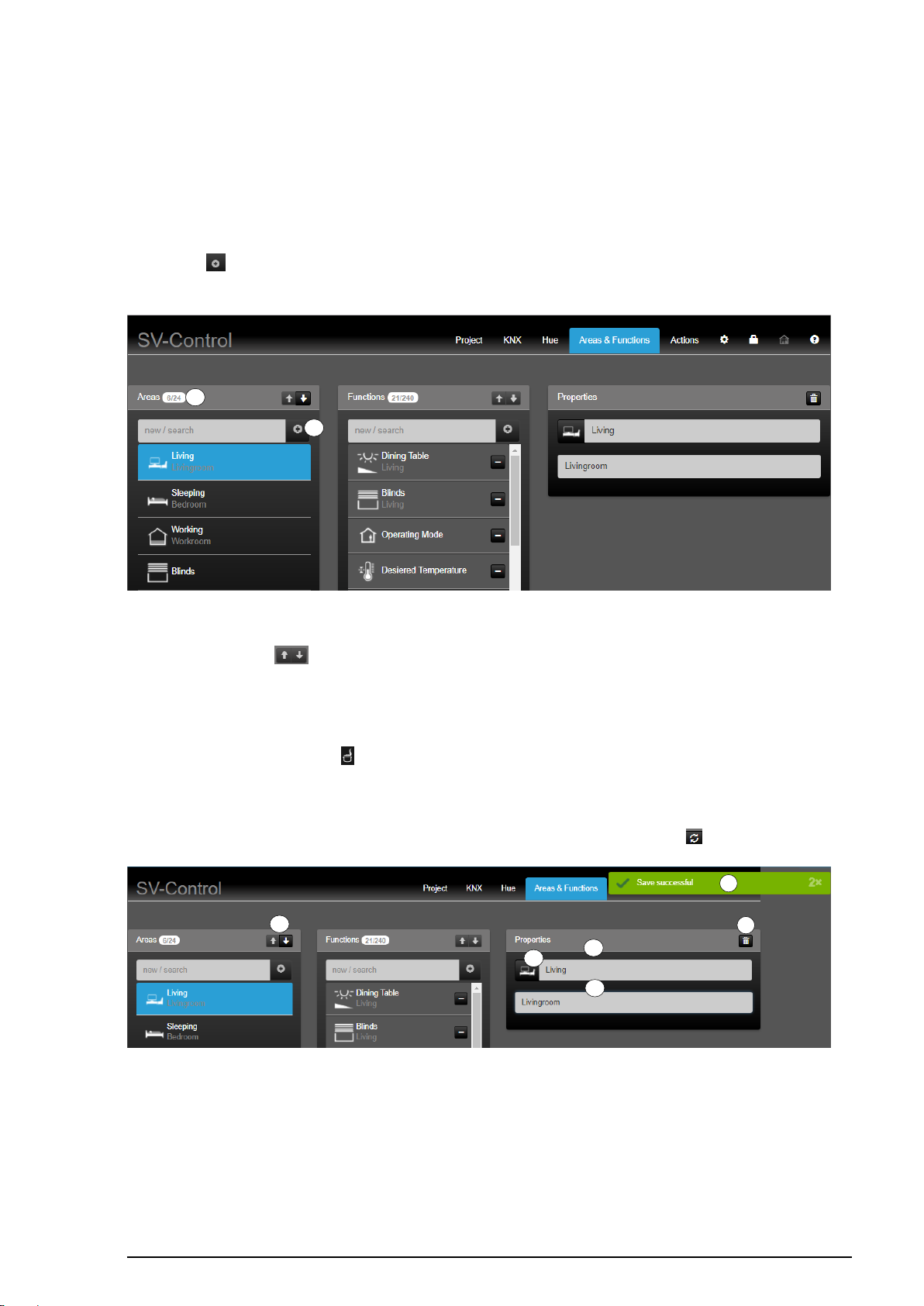
2.4.1 Creating a new area
The up to 24 areas must be provided individual names, icons from the SV-Server library or
additional descriptions. The "User" and the "Administrator" have identical access rights
within the "Areas" column.
To create a new area, enter the name of the new area in the "Areas" column (1) and then
press the " " button (2). The new area is added to the area list with its name and is selected
automatically.
Figure 14: Creating new areas
The arrow buttons " " (3) allow you to change the order of an area, after selecting it, and
thus to move the position in SV-Home. The top area in the SV-Control (from top to bottom)
is displayed as the first area in SV-Home (from left to right).
In the "Properties" column, it is possible to assign an icon to the selected area by pressing
the currently selected icon " " (4) edit the name of the area (5) and, beneath that, add a
description (6).
The changes are saved automatically and briefly displayed by a green display (7) "Save
successful". The most recently saved properties can be restored with the " " button (8).
Figure 15: Individualising created areas
Page 26
SV-SERVER-01 / SV-SERVER-INT 25 / 157
Area
Selection of the icon library in SV-Control
Operating and display element in SV-Home
Area
3 5 4
7
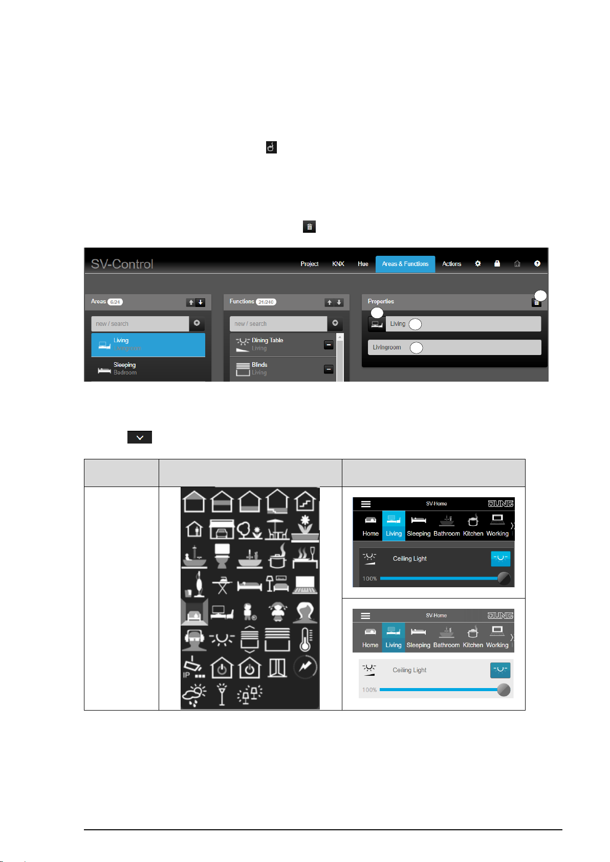
2.4.2 Editing or deleting areas
Select an area to edit or delete it. The "Areas" column lists all the existing areas.
In the "Properties" column, it is possible to assign an alternative icon to the selected area by
pressing the currently selected icon " " (3), edit the name of the area (4) and, beneath that,
add a description (5).
The changes are saved automatically and briefly displayed by a green display "Save
successful".
To fully delete the selected area, press the " " button (7).
Figure 16: Editing or deleting areas
The area possesses has favorites within the symbol library (5). Additional icons are available
via the " " button.
Figure 71: individualization of areas
Page 27
SV-SERVER-01 / SV-SERVER-INT 26 / 157
1 2 3 4 7 6 8
5
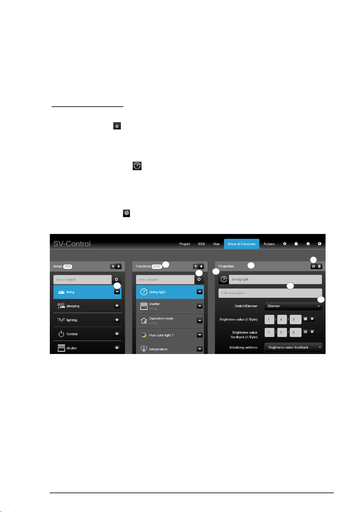
2.4.3 Creating a new function
A function corresponds to, for example, a KNX function, which possibly comprises multiple
group addresses. The up to 240 functions can be given individual names, icons from the
SV-Server library or additional descriptions. Each function can be assigned to one or more
areas or to none.
Access as Administrator
To create a new function, enter the name of the new function in the "Functions" column (1)
and then press the " " button (2). The new function is added in the function list with its
name, is selected automatically and, if necessary, assigned to a selected area (3).
A suitable function must be selected from the defined function types (4) in the "Properties"
column. Then, it is possible to assign an alternative icon to the selected function by pressing
the currently selected icon " " (5), edit the name of the function (6) and, beneath that, add
a description (7).
The changes are automatically saved and briefly displayed by a green "Save successful"
screen.
In addition, the button " " (8) indicates whether the entries of the group addresses are
stored.
Figure 17: Structure of the "Areas and Functions" tab
Page 28
SV-SERVER-01 / SV-SERVER-INT 27 / 157
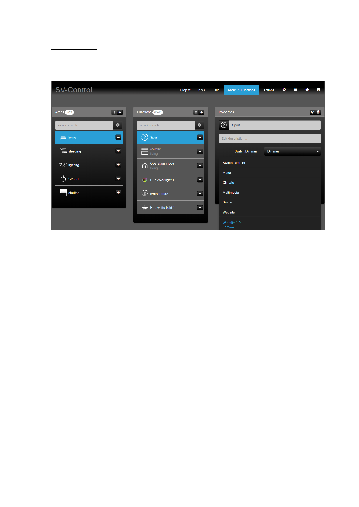
Access as User
You require Administrator rights to be able to create new KNX functions (see chapter
Fehler! Verweisquelle konnte nicht gefunden werden.).
Figure 18: Access rights of the user with access to web functions
Page 29
SV-SERVER-01 / SV-SERVER-INT 28 / 157
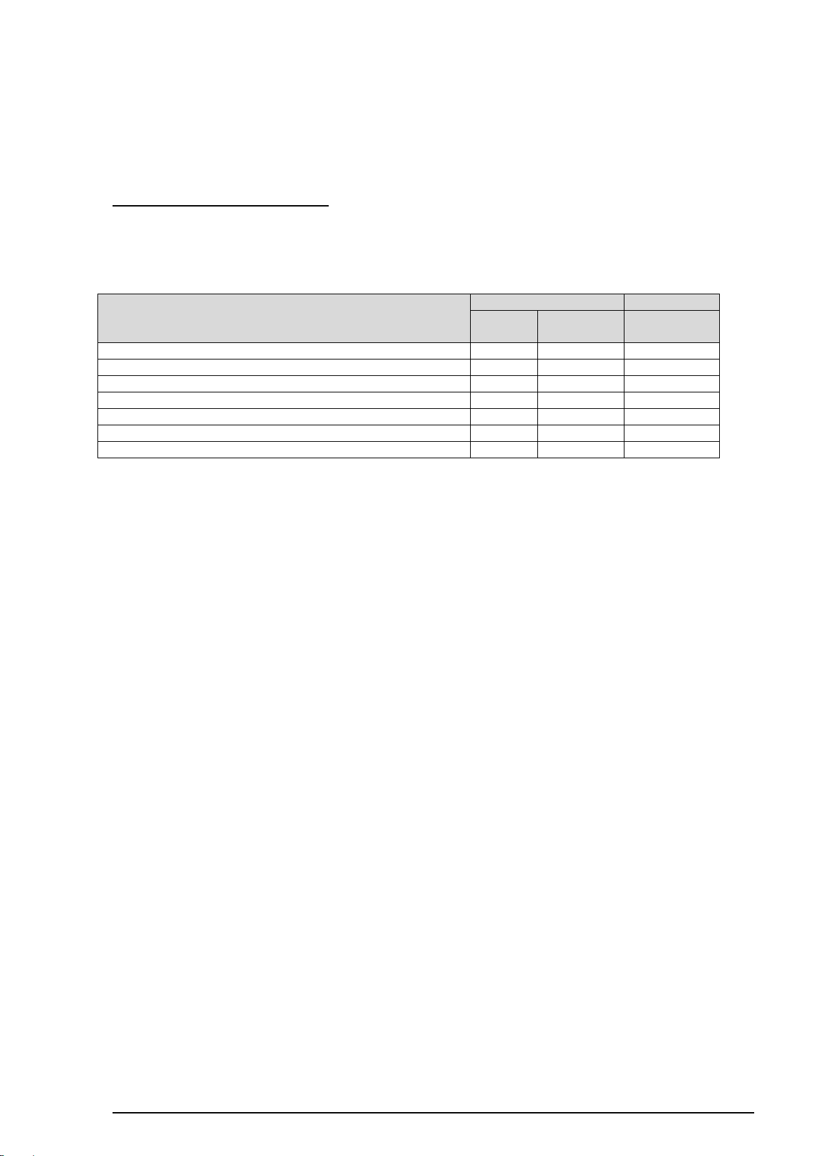
Access
User
Areas &
Function
KNX
Administrator
Create new KNX functions
Edit the names of the KNX functions
Edit the icons of the KNX functions
Assign new existing KNX functions to new areas
Remove existing KNX functions from new areas
Edit the group address of the KNX functions
Permanently delete existing KNX functions
2.4.4 Configuring KNX functions
Successful commissioning of the KNX system and definition of the KNX-IP Gateway in SVControl are required to be able to use KNX functions.
Access as Administrator or User
The "User" and the "Administrator" can have different access rights to KNX functions
within the "Functions" column. The differentiated access rights for locked control boxes at
a glance:
Figure 19: Access rights to KNX functions
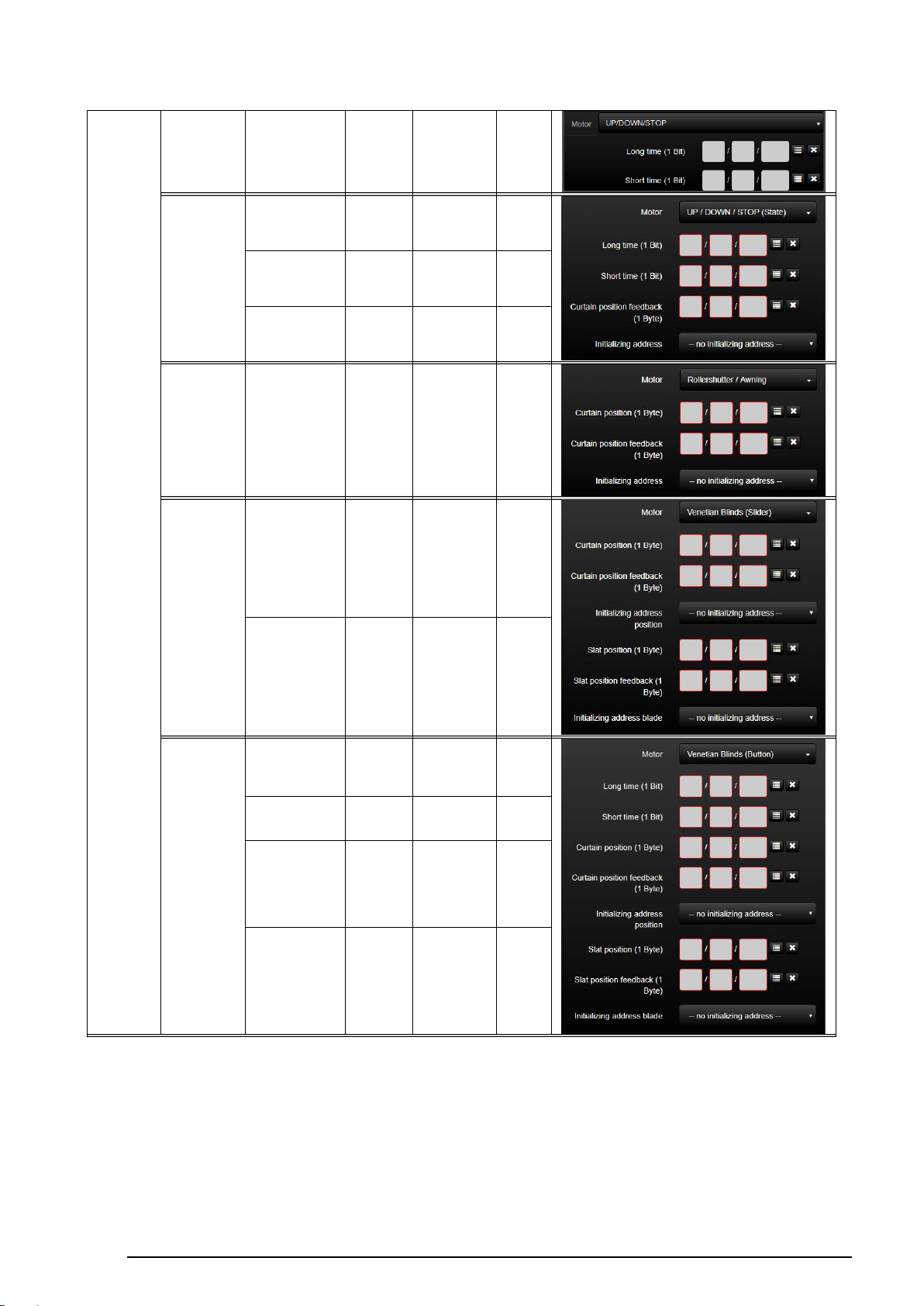
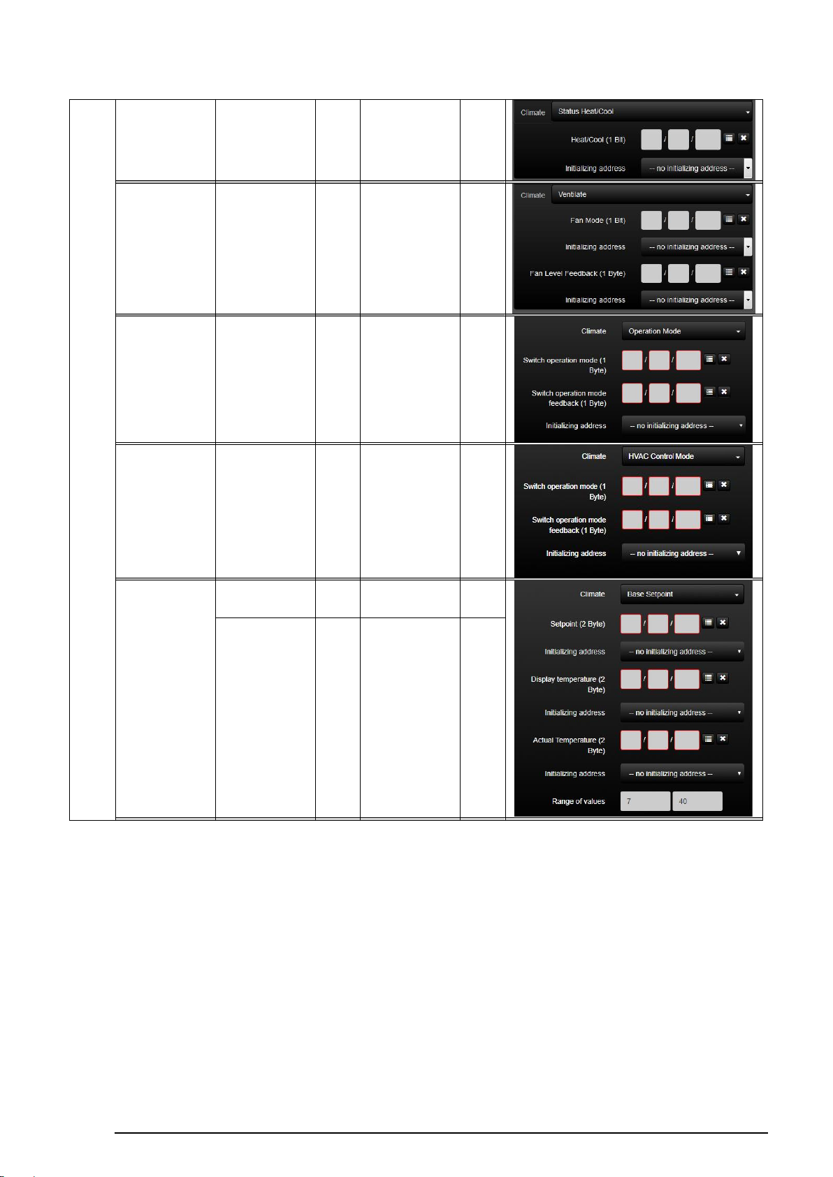
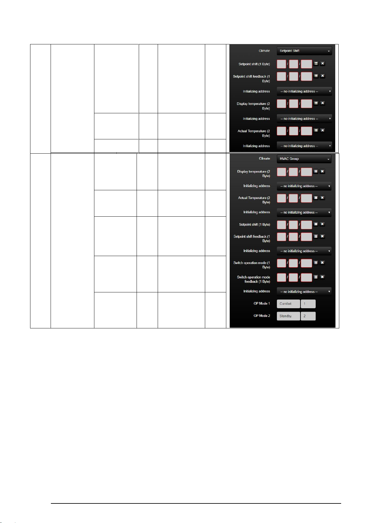
Each KNX function can be described by a specific function type and summarises suitable
ETS group addresses.
The following function types are available to the Administrator:
Page 30

SV-SERVER-01 / SV-SERVER-INT 29 / 157
Function
type
KNX function
KNX group addresses
Depiction in SV-Control
Write addresses
Size
DPT
Read
addresses
Size
[DPT]
Switcher /
Dimmer
Switch
Switch
(1 Bit)
1 Bit
1.001
Switch
feedback
1 Bit
1.001
On / Off
On / Off
(1 Bit)
1 Bit
1.001
---
---
Dimmer
Brightness value
8 Bit
5.001
Brightness
value feedback
8 Bit
5.001
Dimmer/Switch
Brightness value
8 Bit
5.001
Brightness
value feedback
8 Bit
5.001
Switch
Switch
(1 Bit)
1 Bit
1.001
Switch
feedback
RGB
Send value
red
8 Bit
5.001
value red
feedback
8 Bit
5.001
Send value
green
8 Bit
5.001
value green
feedback
8 Bit
5.001
Send value
blue
8 Bit
5.001
value blue
feedback
8 Bit
5.001
Switch
1 Bit
1.001
Switch
feedback
1 Bit
1.001
Motor
UP / DOWN /
STOP
Long time
1 Bit
1.008
---
---
Page 31
SV-SERVER-01 / SV-SERVER-INT 30 / 157
Short time
1 Bit
1.008
---
---
UP / DOWN /
STOP (State)
Long time
1 Bit
1.008
---
--- Short time
1 Bit
1.008
---
---
---
---
Curtain
position
feedback
8 Bit
5.001
Rollershutter/
Awning
Curtain position
8 Bit
5.001
Curtain
position
feedback
8 Bit
5.001
Venetian
Blinds (Slider)
Curtain position
8 Bit
5.001
Curtain
position
feedback
8 Bit
5.001
Slat position
8 Bit
5.001
Slate position
feedback
8 Bit
5.001
Venetian
Blinds
(Button)
Long time
1 Bit
1.008
---
--Short time
1 Bit
1.008
---
---
Curtain position
8 Bit
5.001
Curtain
position
feedback
8 Bit
5.001
Slat position
8 Bit
5.001
Slate position
feedback
8 Bit
5.001
Page 32
SV-SERVER-01 / SV-SERVER-INT 31 / 157
climate
Status
Heat / Cool
---
---
Status
Heat / Cool
1 Bit
1.001
Ventilate
Fan Mode
1 Bit
1.001
Fan level
feedback
8 Bit
5.010
Operation mode
Switch operation
mode
8 Bit
20.102
Switch operation
mode feedback
8 Bit
20.102
HVAC Control
Mode
Switch operation
mode
8 Bit
20.102
Switch operation
mode feedback
8 Bit
20.102
Base Setpoint
Setpoint
16 Bit
9.001
Display
temperature
16 Bit
9.001
---
---
Actual temperature
16 Bit
9.001
Page 33
SV-SERVER-01 / SV-SERVER-INT 32 / 157
Setpoint shift
Setpoint shift
8 Bit
6.010
Setpoint shift
feedback
8 Bit
6.010
---
---
Display
temperature
16 Bit
9.001
---
---
Actual temperature
16 Bit
9.001
HVAC Group
---
---
Display temperature
16 Bit
9.001
---
---
Actual temperature
16 Bit
9.001
Setpoint shift
8 Bit
6.010
Setpoint shift
feedback
8 Bit
6.010
Switch operation
mode
8 Bit
5.010
Switch operation
mode feedback
8 Bit
5.010
Page 34
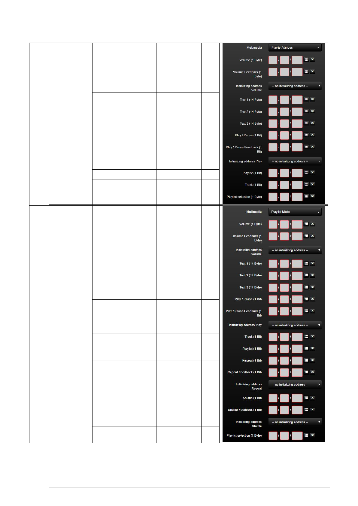
SV-SERVER-01 / SV-SERVER-INT 33 / 157
Mulit-
media
Playlist Various
Volume
8 Bit
5.001
Volume feedback
8 Bit
5.001
Text 1/2/3
14
Byte
16.001
---
---
PlayPause
1 Bit
1.010
PlayPause feedback
1 Bit
1.010
Playlist
1 Bit
1.007
---
---
Track
1 Bit
1.007
---
---
Playlist selection
8 Bit
5.010
---
---
Mulit-
media
Playlist Mode
Volume
8 Bit
5.001
Volume feedback
8 Bit
5.001
Text 1/2/3
14
Byte
16.001
---
--PlayPause
1 Bit
1.010
PlayPause feedback
1 Bit
1.010
Track
1 Bit
1.007
---
---
Playlist
1 Bit
1.007
---
---
Repeat
1 Bit
Repeat feedback
1 Bit
Shuffle
1 Bit
1.003
Shuffle feedback
1 Bit
1.003
Playlist selection
8 Bit
5.010
---
---
Page 35
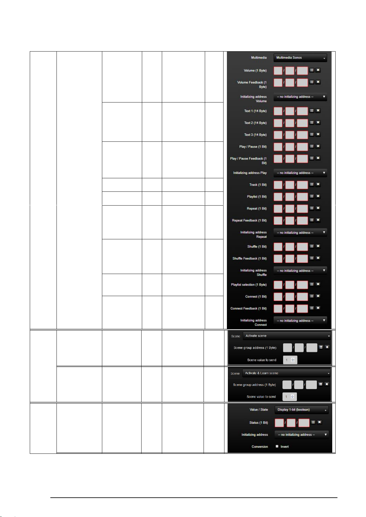
SV-SERVER-01 / SV-SERVER-INT 34 / 157
Mulit-
media
Playlist Mode
Volume
8 Bit
5.001
Volume feedback
8 Bit
5.001
Text 1/2/3
14
Byte
16.001
PlayPause
1 Bit
1.010
PlayPause
feedback
1 Bit
1.010
Track
1 Bit
1.007
---
---
Playlist
1 Bit
1.007
---
---
Repeat
1 Bit
1.003
Repeat feedback
1 Bit
1.003
Shuffle
1 Bit
1.003
Shuffle feedback
1 Bit
1.003
Playlist selection
8 Bit
5.010
Connect
1 Bit
1.017
Connect feedback
1 Bit
1.017
Scene
Activate scene
Scene group
address
8 Bit
18.001
---
---
Activate & learn
scene
Scene group
address
8 Bit
18.001
---
---
Value /
state
Display 1 bit
(boolean)
----
---
Status
1 Bit
e.g.
1.001
Page 36
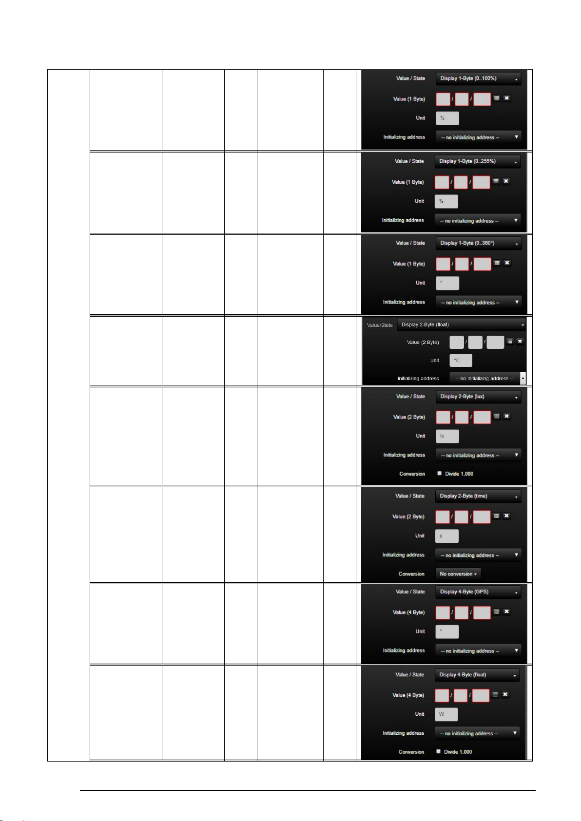
SV-SERVER-01 / SV-SERVER-INT 35 / 157
Display 1 byte
(0...100%)
----
---
Value
8 Bit
e.g.
5.010
Display 1 byte
(0…255%)
----
---
Value
8 Bit
e.g.
5.004
Display 1 byte
(0…360°)
----
---
Value
8 Bit
e.g.
14.007
Display 2 byte
(float)
----
---
Value
16 Bit
e.g.
9.001
Display 2 byte (lux)
----
---
Value
16 Bit
e.g.
7.013
Display 2 byte
(time)
----
---
Value
16 Bit
e.g.
7.005
Display 4 byte
(GPS)
----
---
Value
32 Bit
e.g.
14.007
Display 4 byte value
(float)
----
---
Value
32 Bit
e.g.
14.056
Page 37
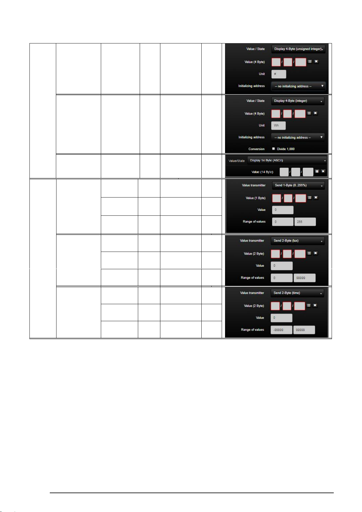
SV-SERVER-01 / SV-SERVER-INT 36 / 157
Display 4 byte value
(unsigned integer)
----
---
Value
32 Bit
e.g.
12.001
Display 4 byte value
(signed integer)
----
---
Value
32 Bit
e.g.
13.013
Display 14 Byte
ASCII
----
---
Value
112 Bit
e.g.
16.001
Value
transmitter
Send 1 byte
(0…255%)
Value
8 Bit
5.004
----
--- Value
0 -255
----
---
Range of
values
0 - 255
----
---
Send 2 byte (lux)
Value
16 Bit
7.013
----
---
Value send
0 -
99999
----
---
Range of
values
0 -
99999
----
---
Send 2 byte (time)
Value
16 Bit
7.005
----
--- Value send
-99999
–
99999
----
---
Range of
values
-99999
- 99999
----
---
Table 108: KNX function types
Page 38
SV-SERVER-01 / SV-SERVER-INT 37 / 157
KNX function
Selection of the icon library in SV-Control
Operating and display element in SV-Home
Switch
1 2 4 5 3
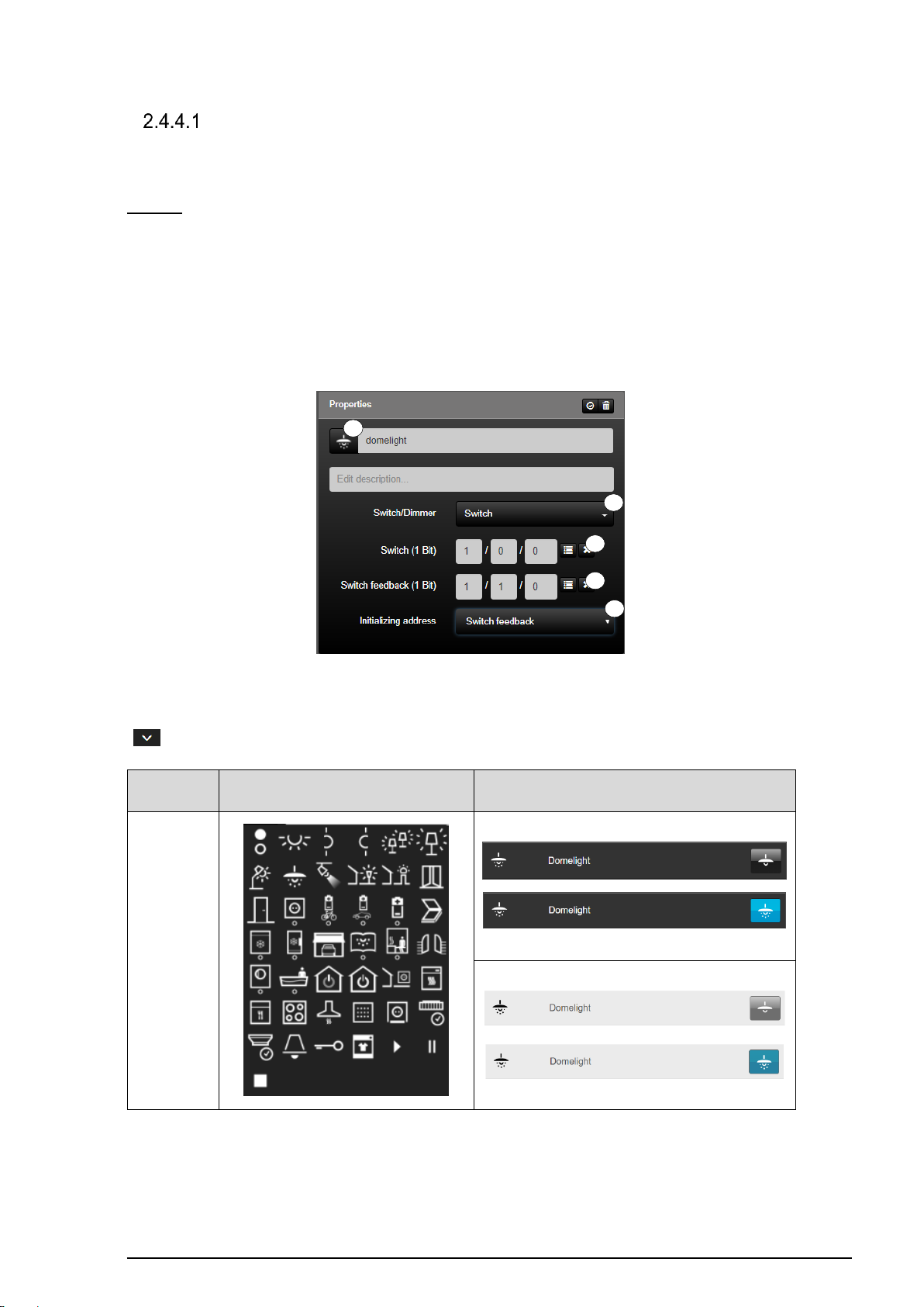
Switch / Dimmer
If required, the function type "Switch / Dimmer" can be depicted by four KNX functions.
Switch:
The "Switch" function (1) is the standard KNX function for simply switching on and off of
switching actuators. In the "Switch" function, a group address can be defined for writing
"Switch" status changes (2) as can a group address for reading "Switch feedback" feedback
(3).
In addition, the current status of a group address can be polled by defining an initialisation
address (4) on starting the system.
Figure 20: Parameters of the "Switch" function
The function has favorites within the symbol library (5). Additional icons are available via the
" " button.
Table 2: Display of the "Switch" function
Page 39
SV-SERVER-01 / SV-SERVER-INT 38 / 157
KNX
function
Selection of the icon library in SV-Control
Operating and display element in SV-Home
On / Off
1
2 3 4
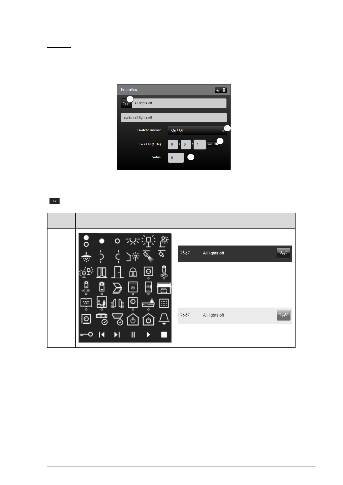
On / Off:
The "On / Off" (1) function is stateless (without feedback) for targeted triggering of a
switching signal (e.g. only switch-off). A group address "On/Off" (2) can be configured for
writing of the value specified in the input field "Value" (3).
Figure 21: Parameters of the "On/Off" function
The function has favorites within the symbol library (4). Additional icons are available via the
" " button.
Table 3: Display of the "On / Off" function
Page 40
SV-SERVER-01 / SV-SERVER-INT 39 / 157
KNX-Funktion
Auswahl der Symbol-Bibliothek
im SV-Control
Bedien- und Anzeigeelement
in der SV-Home
Dimmer
1 3 4
5
2
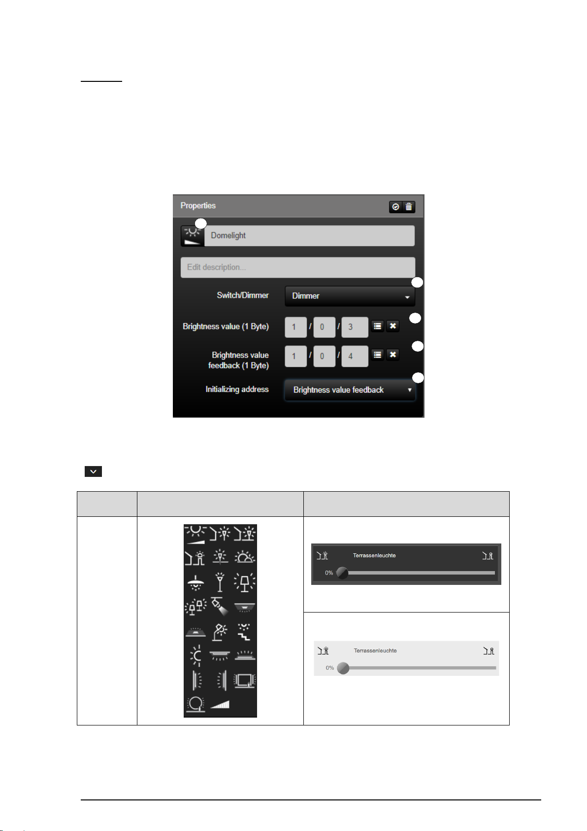
Dimmer:
The "Dimmer" function (1) is used for simple dimming of dimmer actuators. A "Brightness
value" (2) group address can be configured for switching or writing a new brightness value.
In the same way, to read the feedback, it is possible to configured the group addresses
"Brightness value feedback" (3).
In addition, the current status of a selectable group address can be polled by defining an
initialisation address (5) on starting the system.
Figure 22: Parameters of the "Dimmer" function
The function has favorites within the symbol library (5). Additional icons are available via the
" " button.
Table 4: Darstellung der Funktion „Dimmer“
Page 41
SV-SERVER-01 / SV-SERVER-INT 40 / 157
KNX function
Selection of the icon library in SV-Control
Operating and display element in SV-Home
Dimmer +
Switch
1 2 3 4 5 7 6
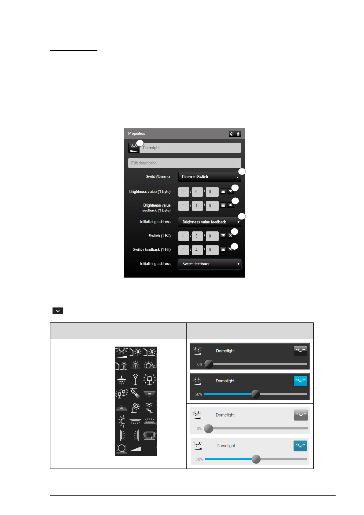
Dimmer/Switch:
The "Dimmer + Switch" function (1) is used for simple dimming of dimmer actuators. A
"Switching" (2) and / or "Brightness value" (4) group address can be configured for switching
or writing a new brightness value. In the same way, to read the feedback, it is possible to
configured the group addresses "Switching feedback" (3) and "Brightness value feedback"
(5).
In addition, the current status of a selectable group address can be polled by defining an
initialisation address (6) on starting the system.
Figure 23: Parameters of the "Dimmer/Switch" function
The function has favorites within the symbol library (7). Additional icons are available via the
" " button.
Table 5: Display of the "Dimmer" function
Page 42
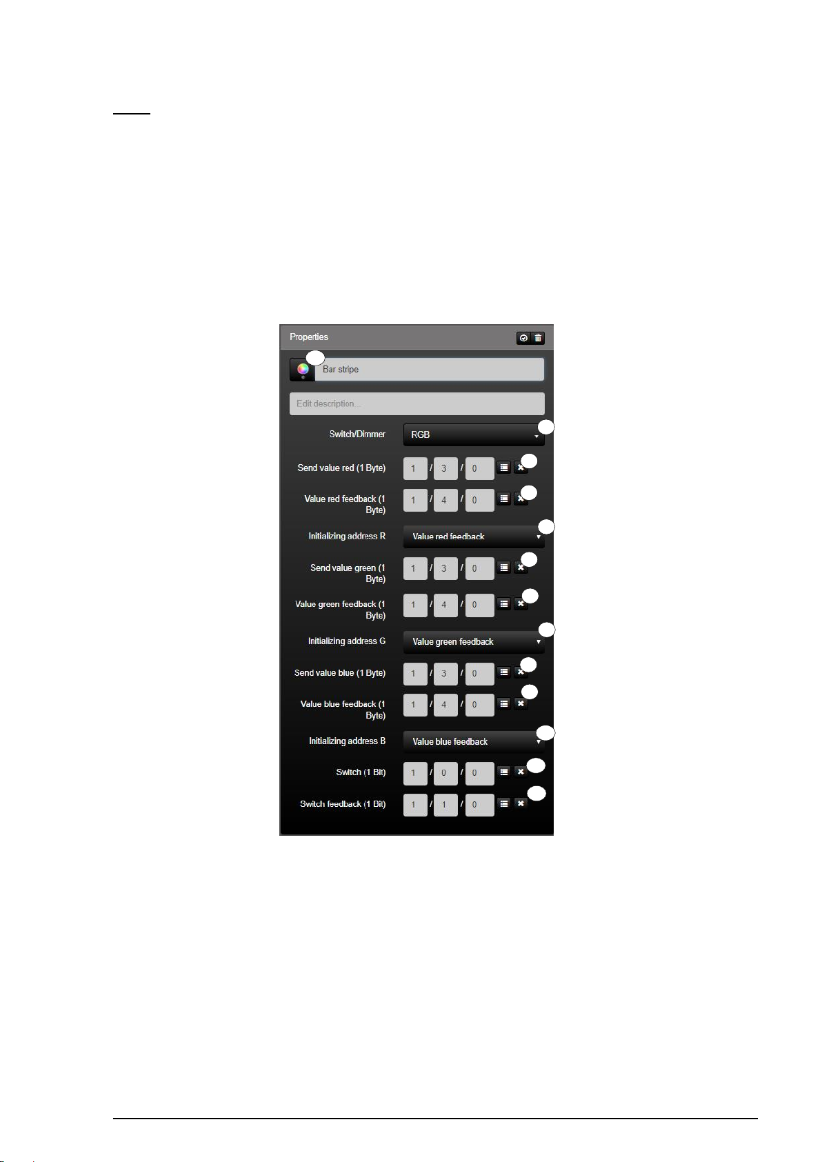
SV-SERVER-01 / SV-SERVER-INT 41 / 157
1
2 3 4
5
13
6 7 8 9 10
11
12
RGB:
The "RGB" function (1) is the KNX function for controlling RGB dimmer actuators. With the
group address, e.g. "Transmit value red" (2), it is possible to write the current brightness
value of the red colour channel to the bus. The "Value red feedback" group address (3) can
be defined to read the current brightness of the red colour channel.
In addition, the current status of a selectable group address of the colour channel can be
polled by defining an initialisation address red (4) on starting the system. The same applies
to the green (5 - 7) and blue (8 - 10) colour channel. The "Switching" group address (11) can
be defined for central switching of the function. The switching state of the function can also
be read via the "Switching feedback" group address (12).
Figure 24: Parameters of the "RGB (KNX)" function
Page 43
SV-SERVER-01 / SV-SERVER-INT 42 / 157
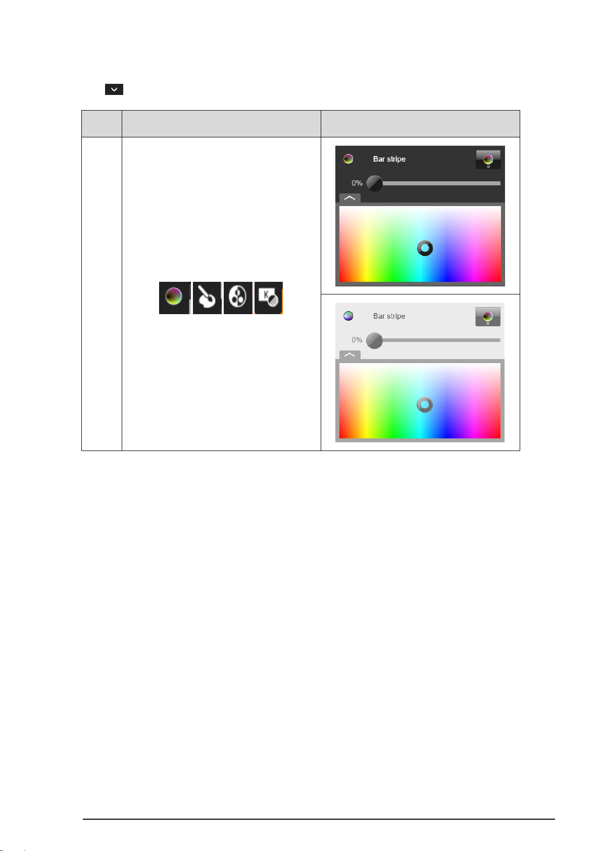
KNX
function
Selection of the icon library in SV-Control
Operating and display element in SV-Home
RGB
The function has favorites within the symbol library (13). Additional icons are available via
the " " button.
Table 6: Display of the "RGB (KNX)" function
Page 44
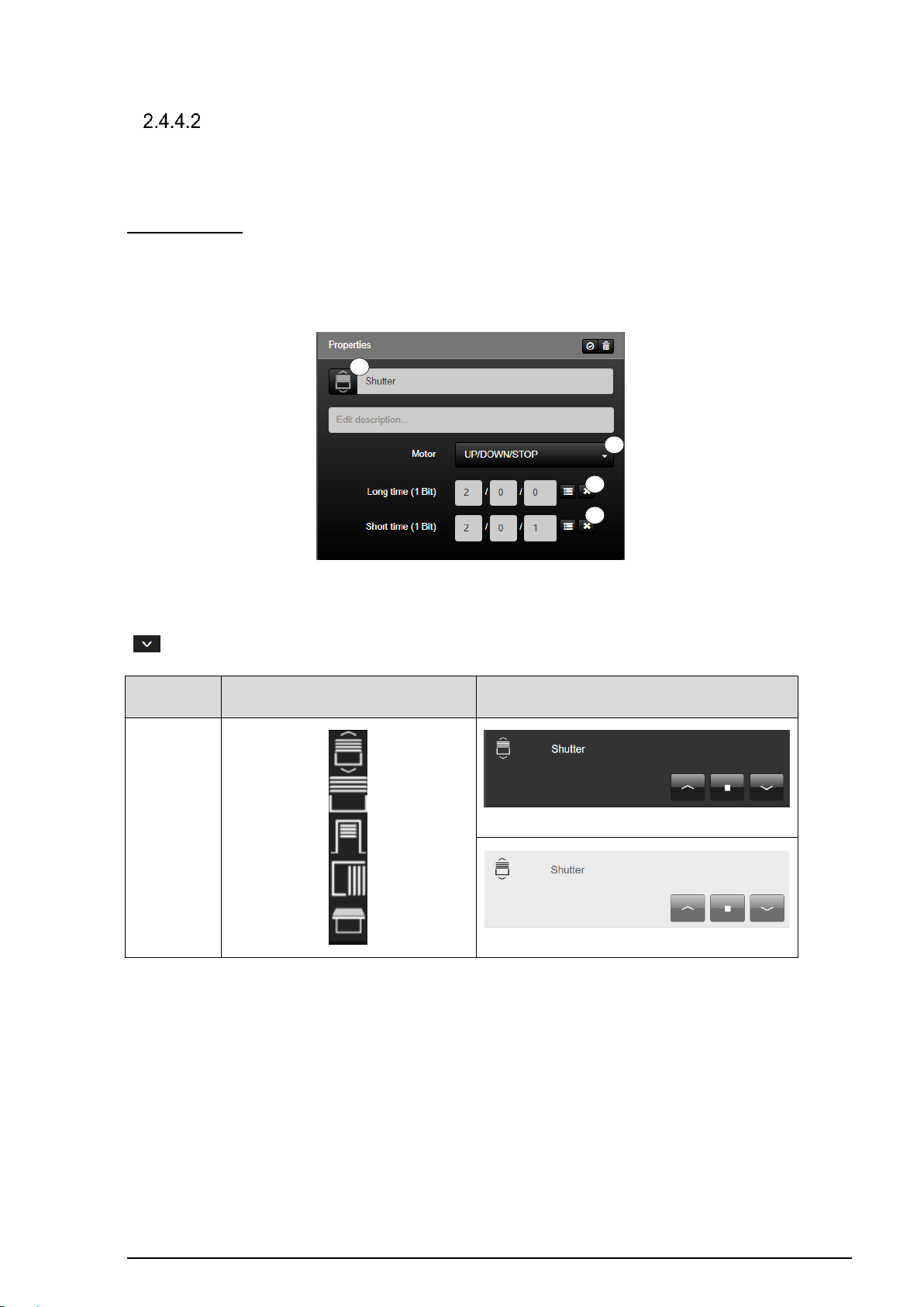
SV-SERVER-01 / SV-SERVER-INT 43 / 157
KNX function
Selection of the icon library in SV-Control
Operating and display element in SV-Home
Up / Down /
Stop
1 2 3
4
Motor
If required, the function type "Motor" can be depicted by one of three KNX functions.
Up/Down/Stop:
The "UP/DOWN/STOP" function (1) is the KNX function for simple control of motorised
drives without feedback objects. The motorised drive can be activated by the group
addresses "Long time" (2) and "Short time" (3).
Figure 25: Parameters of the "Up/Down/Stop" function
The function has favorites within the symbol library (4). Additional icons are available via the
" " button.
Table 7: Display of the "Up/Down/Stop" function
Page 45
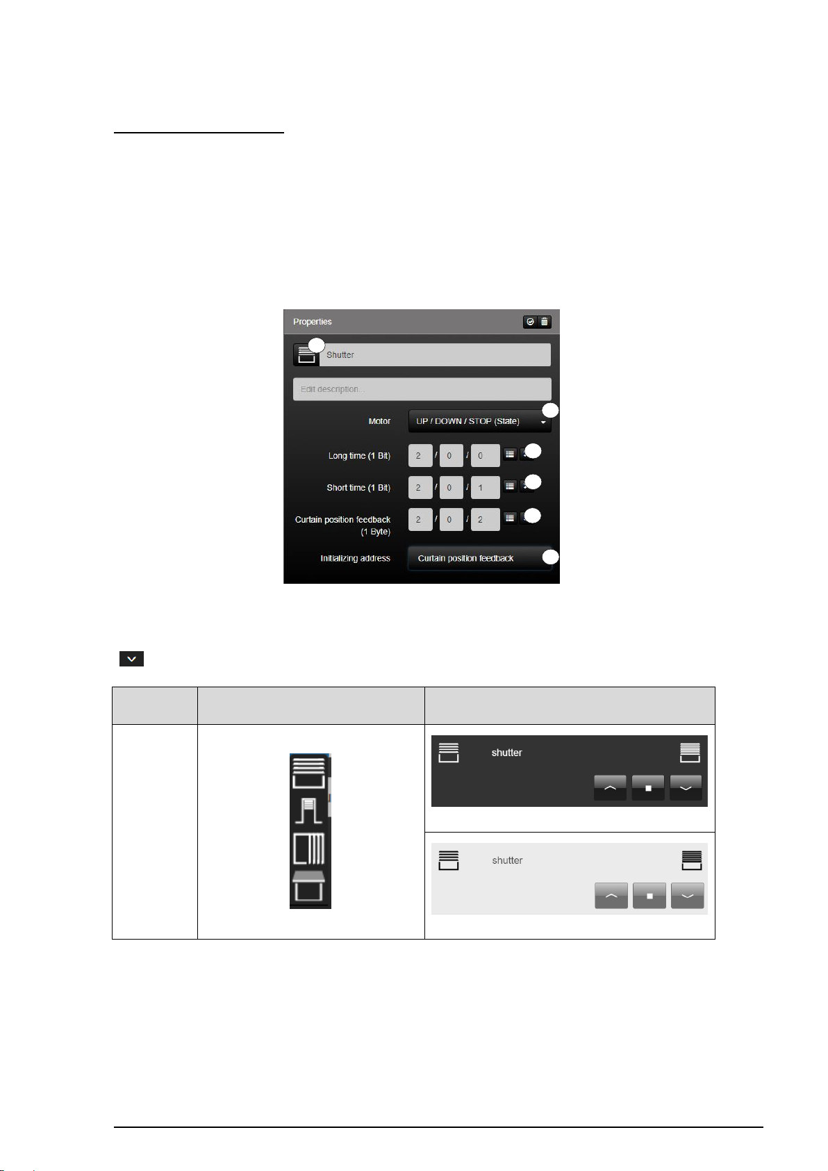
SV-SERVER-01 / SV-SERVER-INT 44 / 157
KNX function
Selection of the icon library in SV-Control
Operating and display element in SV-Home
Up/Down/Stop
(State)
1 2 3
4 6 5
Up / Down / Stop (State):
The "UP/DOWN/STOP (State)" function (1) is the KNX function for simple control of
motorised drives with feedback objects. The motorised drive can be activated by the group
addresses "Long time" (2) and "Short time" (3).
The "Position feedback" (4) group address must be configured for reading the position. In
addition, the current status of a selectable group address can be polled by defining an
initialisation address (5) on starting the system.
Figure 26: Parameters of the "Up/Down/Stop (State)" function
The function has favorites within the symbol library (6). Additional icons are available via the
" " button.
Table 8: Display of the "Up/Down/Stop (State)" function
Page 46
SV-SERVER-01 / SV-SERVER-INT 45 / 157
1
2 3 4
5
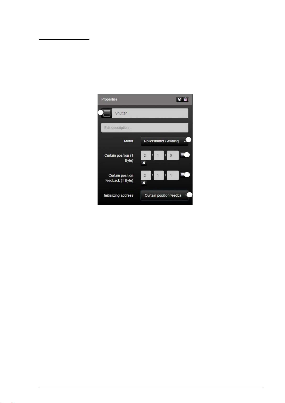
Rollershutter/Awning:
The “Rollershutter/Awning” function (1) is the KNX function for control of motorised roller
shutters/awnings with position specification. The motorised drive can be activated by the
group address "Position specification" (2).
The "Position feedback" (3) group address must be configured for reading the position. In
addition, the current status of a selectable group address can be polled by defining an
initialisation address (4) on starting the system.
Figure 27: Parameters of the "Rollershutter/Awning" function
Page 47
SV-SERVER-01 / SV-SERVER-INT 46 / 157
KNX function
Selection of the icon library in SV-Control
Operating and display element in SV-Home
Rollershutter/Awning
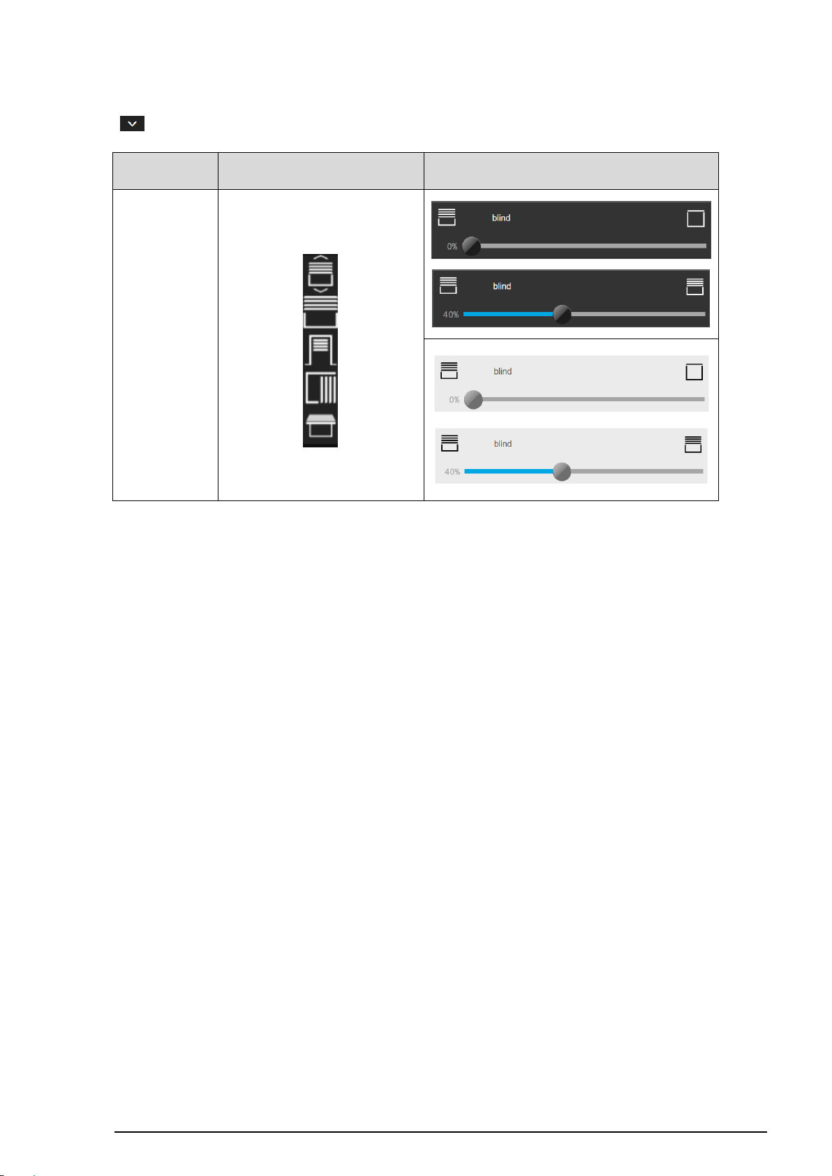
The function has favorites within the symbol library (5). Additional icons are available via the
" " button.
Table 9: Display of the "Rollershutter/Awning" function
Page 48
SV-SERVER-01 / SV-SERVER-INT 47 / 157
1 2 3
4 5 6 7 8
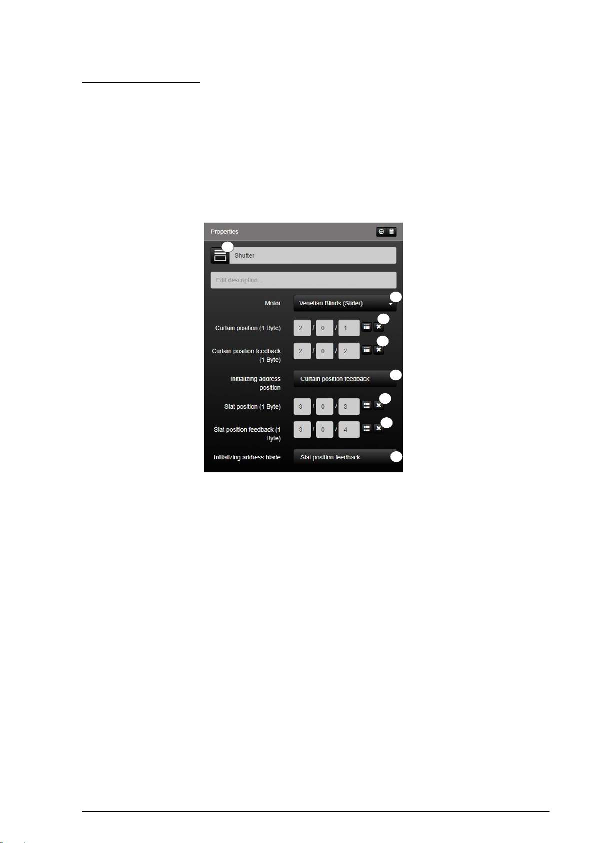
Venetian Blinds (Slider):
The "Venetian Blinds (Slider)" function (1) is the KNX function for controlling motorised
Venetian blinds with position and slat specification. The motorised drive can be activated by
the group addresses "Position specification" (2) and "Slat specification" (4).
To read the positions, it is possible to configured the group addresses "Feedback position"
(3) and "Slat feedback" (5).
In addition, the current status of the function can be polled by defining two initialisation
addresses (6 - 7) on starting the system.
Figure 28: Parameters of the "Venetian Blinds (Slider)" function
Page 49
SV-SERVER-01 / SV-SERVER-INT 48 / 157
KNX function
Selection of the icon library in SV-Control
Operating and display element in SV-Home
Venetian
Blinds (Slider)
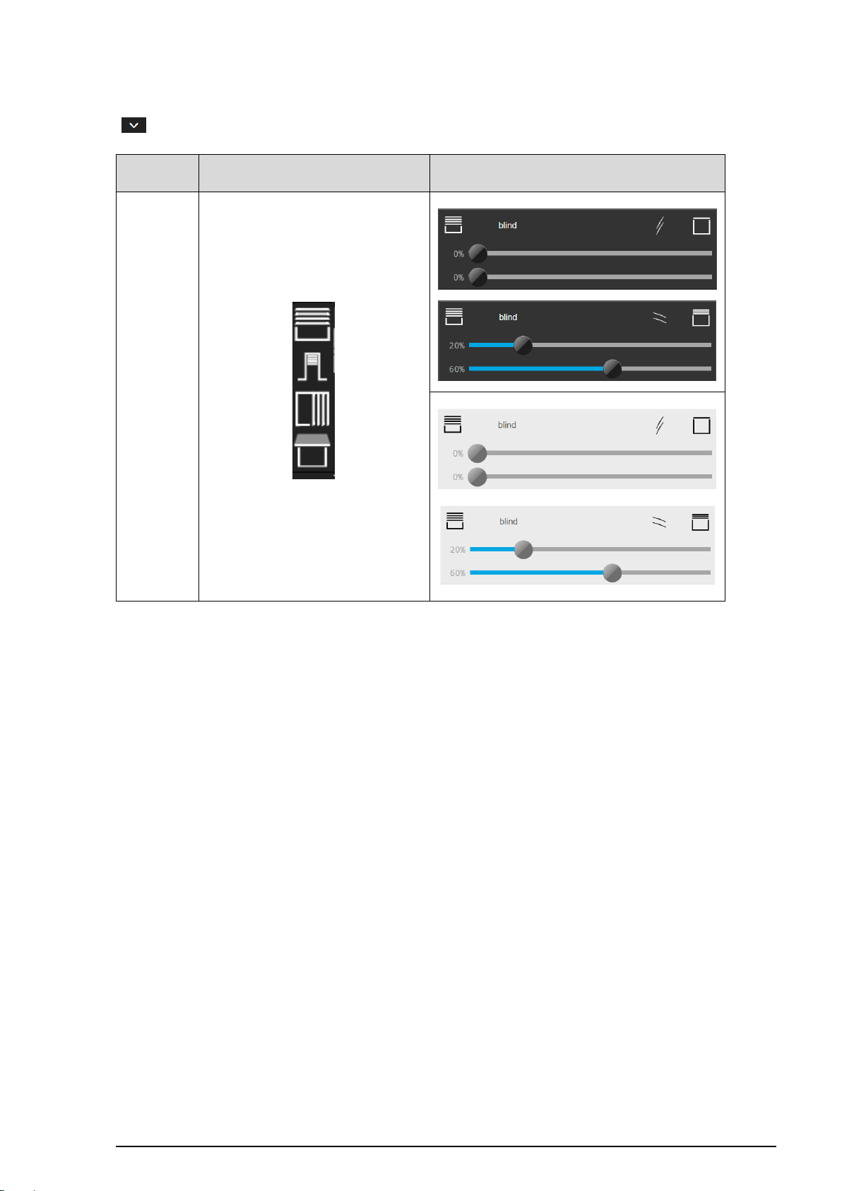
The function has favorites within the symbol library (8). Additional icons are available via the
" " button.
Table 10: Display of the "Venetian Blinds (Slider)" function
Page 50
SV-SERVER-01 / SV-SERVER-INT 49 / 157
1 2 3
4
5 6 10
7 9 8
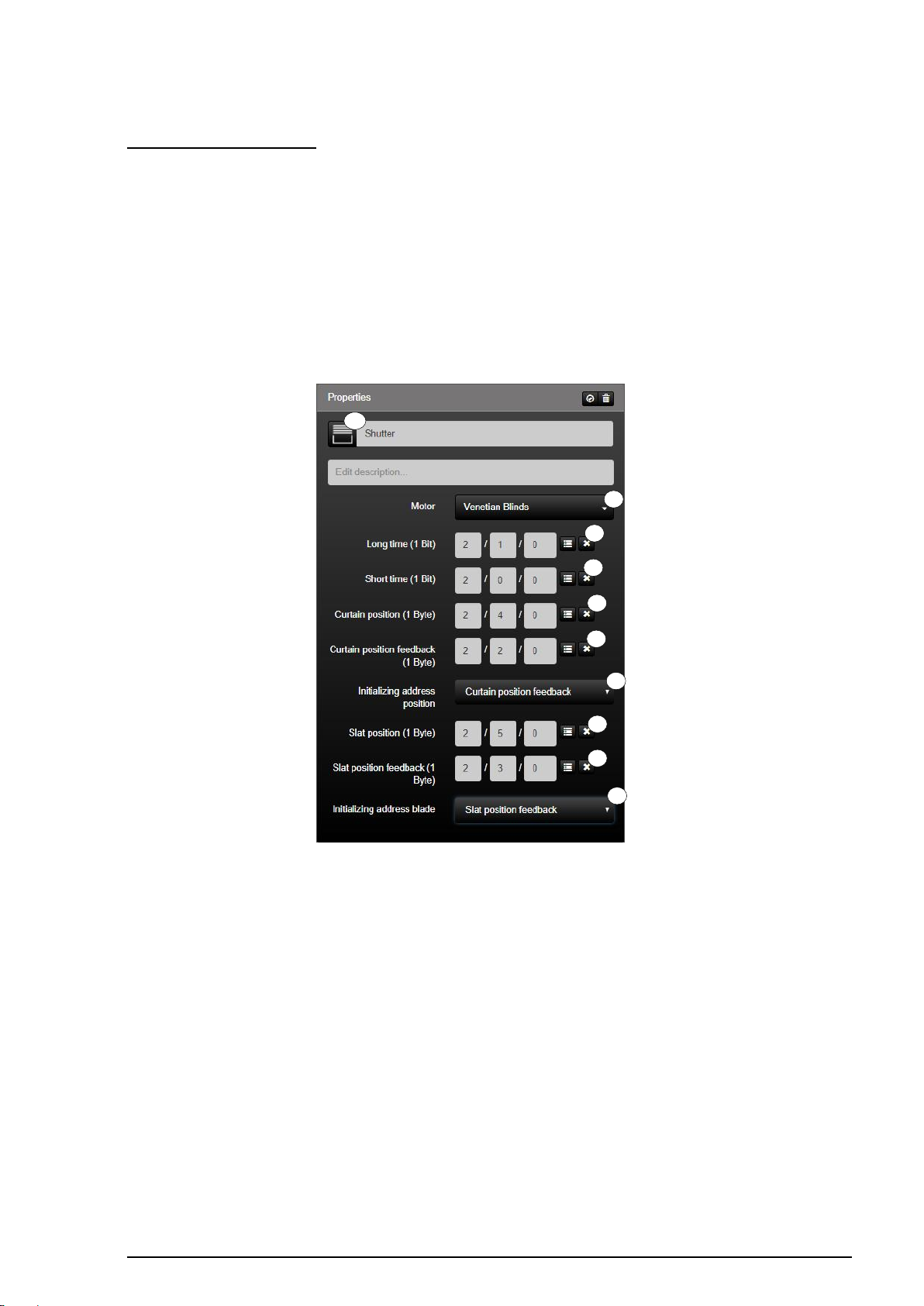
Venetian Blinds (Button):
The "Venetian Blinds (Button)" function (1) is the KNX function for controlling motorised
Venetian blinds with position and slat specification. The motorised drive can be activated by
the group addresses "Long time" (2), "Short time" (3), "Position specification" (4) and "Slat
specification" (5).
To read the positions, it is possible to configured the group addresses "Feedback position"
(6) and "Slat feedback" (7).
In addition, the current status of the function can be polled by defining two initialisation
addresses (8 - 9) on starting the system.
Figure 29: Parameters of the "Venetian Blinds (Button)" function
Page 51
SV-SERVER-01 / SV-SERVER-INT 50 / 157
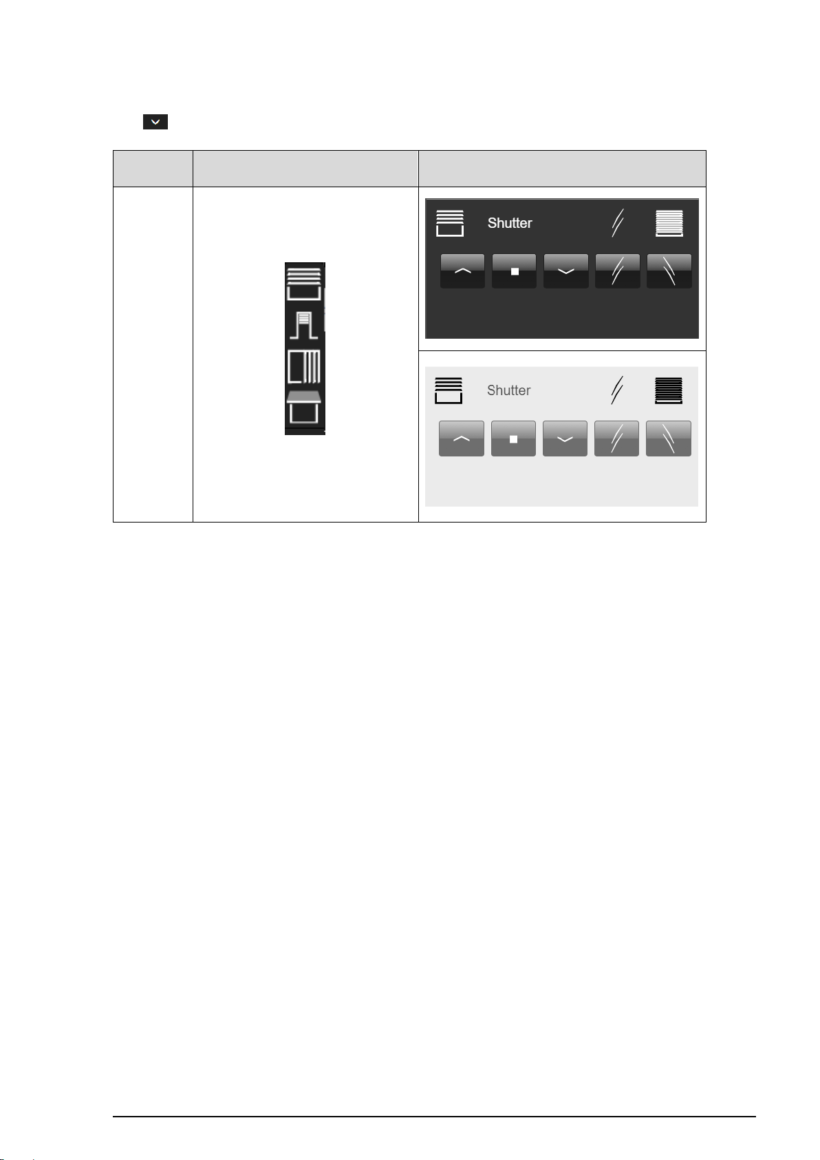
KNX function
Selection of the icon library in SV-Control
Operating and display element in SV-Home
Venetian
Blinds (Button)
The function has favorites within the symbol library (10). Additional icons are available via
the " " button.
Table 11: Display of the "Venetian Blinds (Button)" function
Page 52
SV-SERVER-01 / SV-SERVER-INT 51 / 157
KNX function
Selection of the icon library in SV-Control
Operating and display element in SV-Home
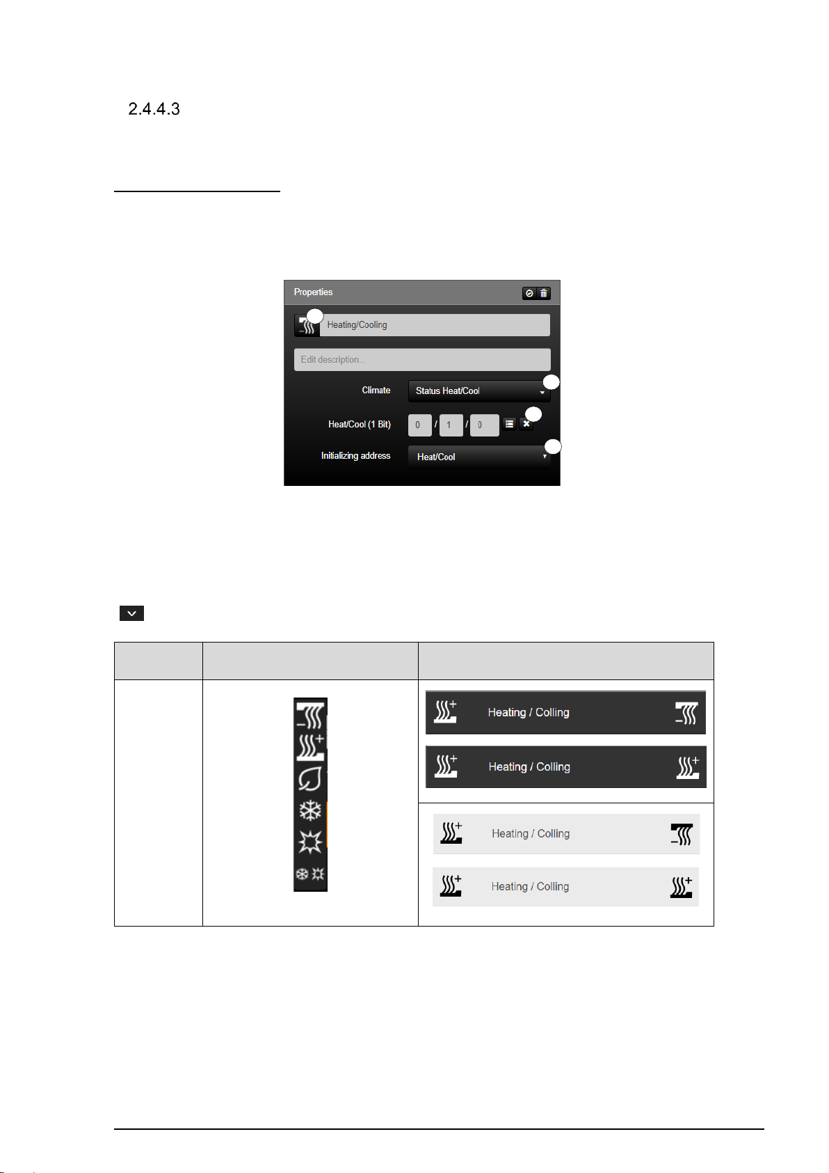
Status Heat/Cool
1 2 3
4
Climate
If required, the function group "Climate" can be depicted by various KNX functions.
Status Heat/Cool (KNX):
The "Status Heat / Cool" function (1) allows the display of the current status of a binary
climate actuator system. If, for example, your electrical underfloor heating is switched on,
then this function can be displayed in SV-Home.
Figure 30: Parameters of the "Status Heat/Cool" function
The group address to be visualised can be specified in the input field (2). Using the selection
menu (3), you can specify this group address as the initialisation address for this function.
The function has favorites within the symbol library (4). Additional icons are available via the
" " button.
Table 12: Display of the "Status Heat / Cool" function
Page 53
SV-SERVER-01 / SV-SERVER-INT 52 / 157
KNX function
Selection of the icon library
in SV-Control
Operating and display element
in SV-Home
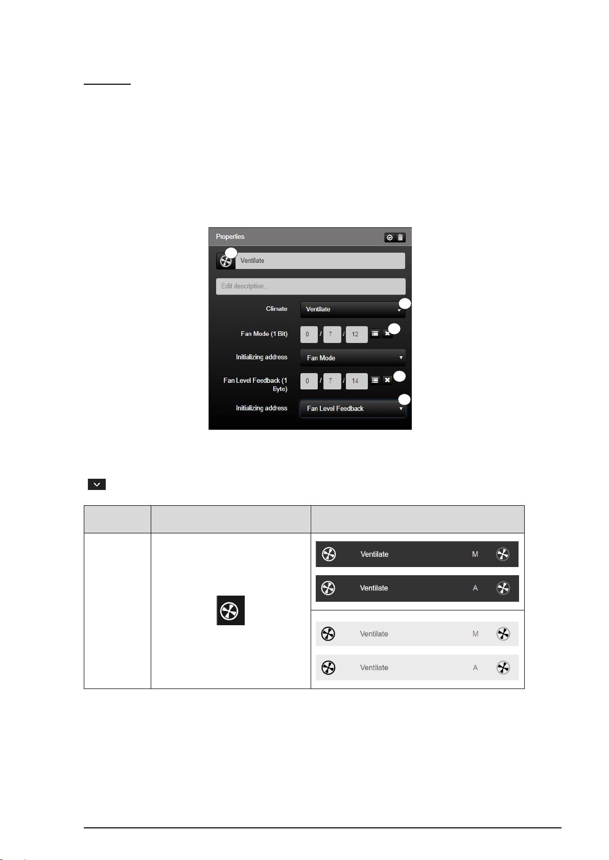
Ventilate
1 2 3 5 4
Ventilate:
The "Ventilate" function (1) allows the display and control of the status of a KNX ventilation
controller.
In the input field (2), it is possible to specify the group address for controlling the fan and, in
the input field (3), it is possible to enter the group address for the feedback of the currently
set fan step.
One of the two group addresses can be selected for the initialisation (4) of the Smart Visu
Server on its system start.
Figure 31: Parameters of the "Ventilate" function
The function has favorites within the symbol library (5). Additional icons are available via the
" " button.
Table 13: Display of the "Ventilate" function
Page 54
SV-SERVER-01 / SV-SERVER-INT 53 / 157
KNX function
Selection of the icon library in SV-Control
Operating and display element in SV-Home
Operation Mode
1
2
3 4 5
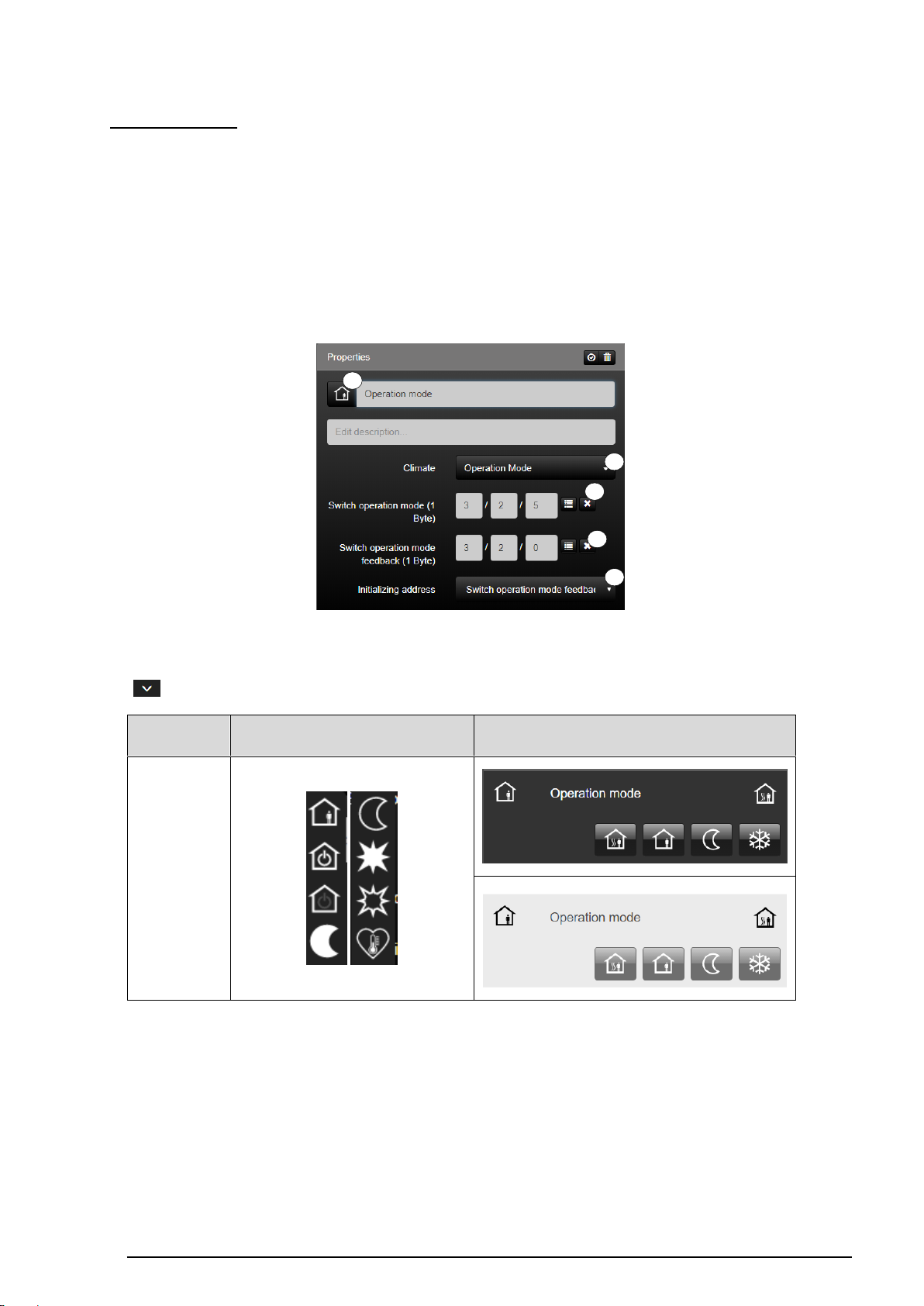
Operation Mode:
The function "operating mode" (1) is the function for switching the different operating
modes in accordance with the KNX. This can be initiated by the group address "operating
mode changeover" (2).
The current operating mode can be read by the group address "Operating mode feedback"
(3).
In addition, by declaring an initialization address (4) at system startup, the current status of
the function can be queried.
Figure 32: Parameters of the "Operating Mode" function
The function has favorites within the symbol library (5). Additional icons are available via the
" " button.
Table 14: Display of the "Operation Mode" function
Page 55
SV-SERVER-01 / SV-SERVER-INT 54 / 157
KNX function
Selection of the icon library in SV-Control
Operating and display element in SV-Home
Operation Mode
2 3 1
4
5
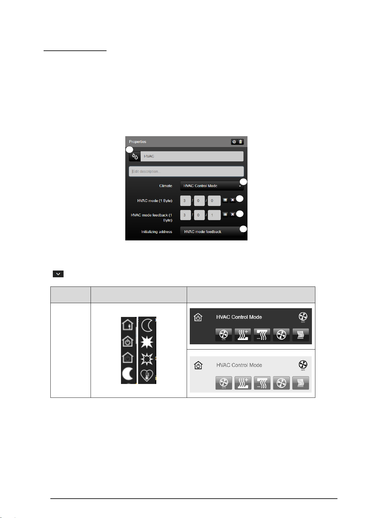
HVAC Control Mode:
With the function "HVAC control mode" (1), you can switch between heating / cooling and
ventilation manually / auto. Switched by the group address "operating mode switching" (2).
The current operating mode can be read by the group address "Operating mode feedback"
(3).
In addition, by defining two initialization addresses (4) during system startup, the current
status of the function can be queried.
Figure 33: Parameters of the "HVAC Control Mode" function
The function has favorites within the symbol library (5). Additional icons are available via the
" " button.
Table 15: Display of the "HVAC Control Mode" function
Page 56
SV-SERVER-01 / SV-SERVER-INT 55 / 157
KNX function
Selection of the icon library in SV-Control
Operating and display element in SV-Home
Base Setpoint
1 2 3 4 5 6 9
8
7
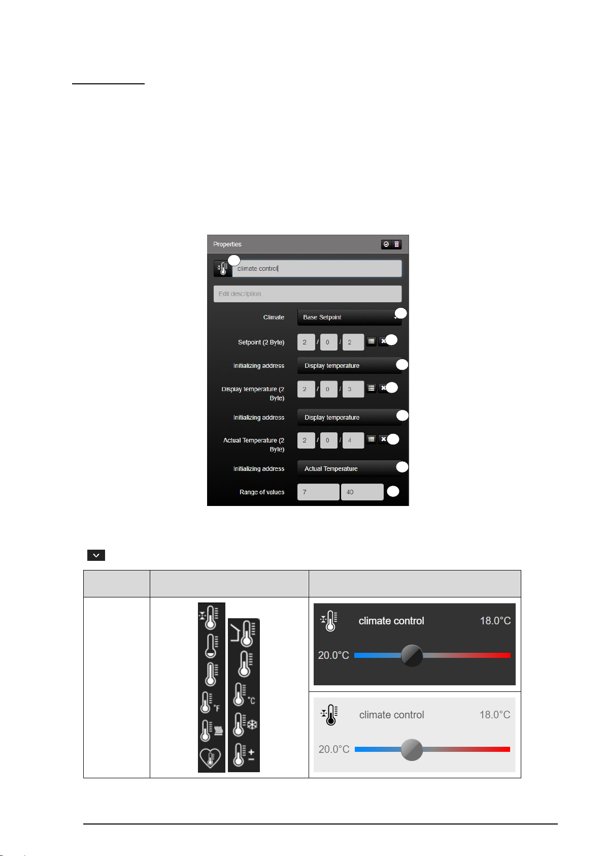
Base Setpoint:
The Smart Visu Server supports KNX climate control by specifying a base setpoint (1). The
temperature control can be influenced by the group address "basic setpoint" (2).
The reading of the current setpoint and the current actual value can be configured by the
group addresses "Display temperature" (3) and "Actual temperature" (4).
In addition, by defining three initialization addresses (5 - 7) at system startup, the current
status of the function can be queried.
Moreover, the “Range of values” (8) can be set individually.
Figure 34: Parameters of the "Base Setpoint" function
The function has favorites within the symbol library (9). Additional icons are available via the
" " button.
Table 16: Display of the "Base Setpoint" function
Page 57
SV-SERVER-01 / SV-SERVER-INT 56 / 157
KNX function
Selection of the icon library in SV-Control
Operating and display element in SV-Home
Setpoint Shift
1 2 3 4 5 6 7 9 8
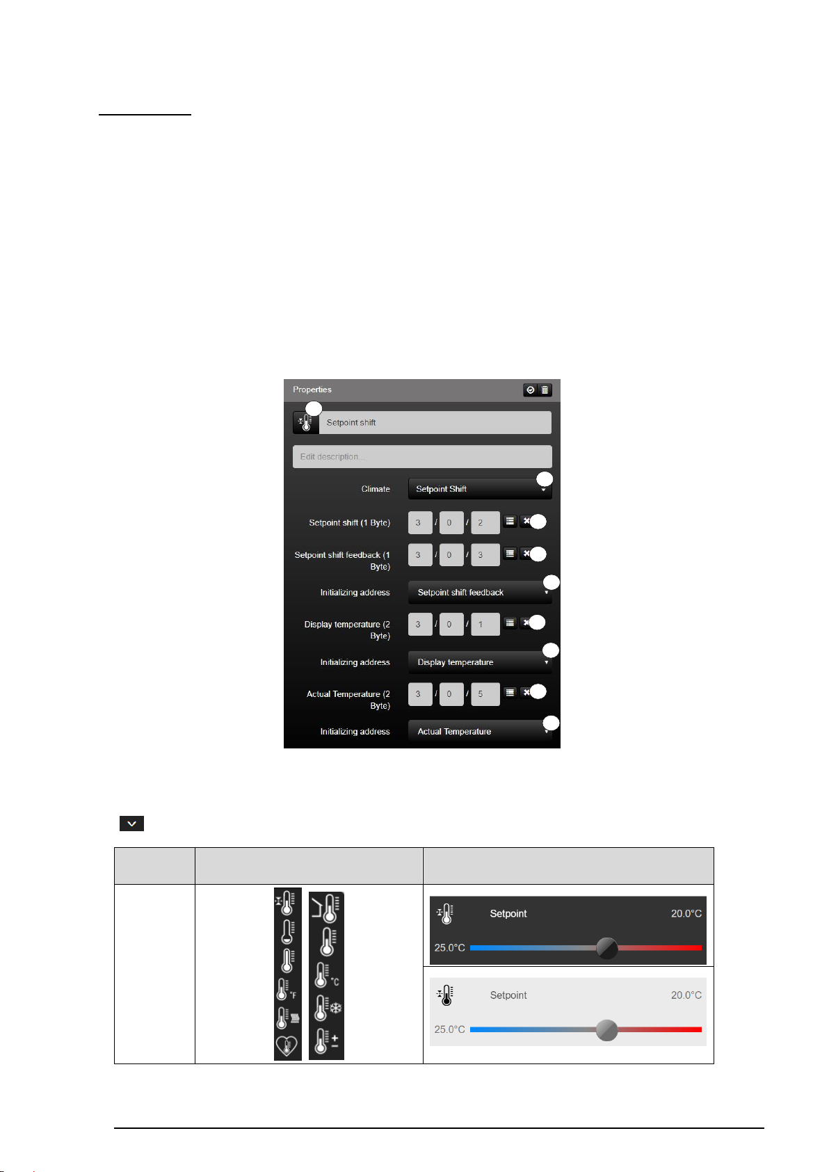
Setpoint shift:
With the function "Setpoint adjustment" (1), a KNX climate control can be influenced via
the setpoint shift. The group address "Setpoint shift" (2) can be used to influence the
temperature control.
Reading the current setpoint shift can be configured by the corresponding feedback
addresses (3).
Furthermore, the current values can be displayed via the setpoint temperature display (4)
and the actual temperature display (8).
In addition, by declaring two initialization addresses (5-7) at system startup, the current
status of the function can be queried.
Figure 35: Parameters of the "Setpoint Shift" function
The function has favorites within the symbol library (9). Additional icons are available via the
" " button.
Table 17: Display of the "Setpoint Shift" function
Page 58
SV-SERVER-01 / SV-SERVER-INT 57 / 157
1
2 3 5 4 6 6 6 6 7
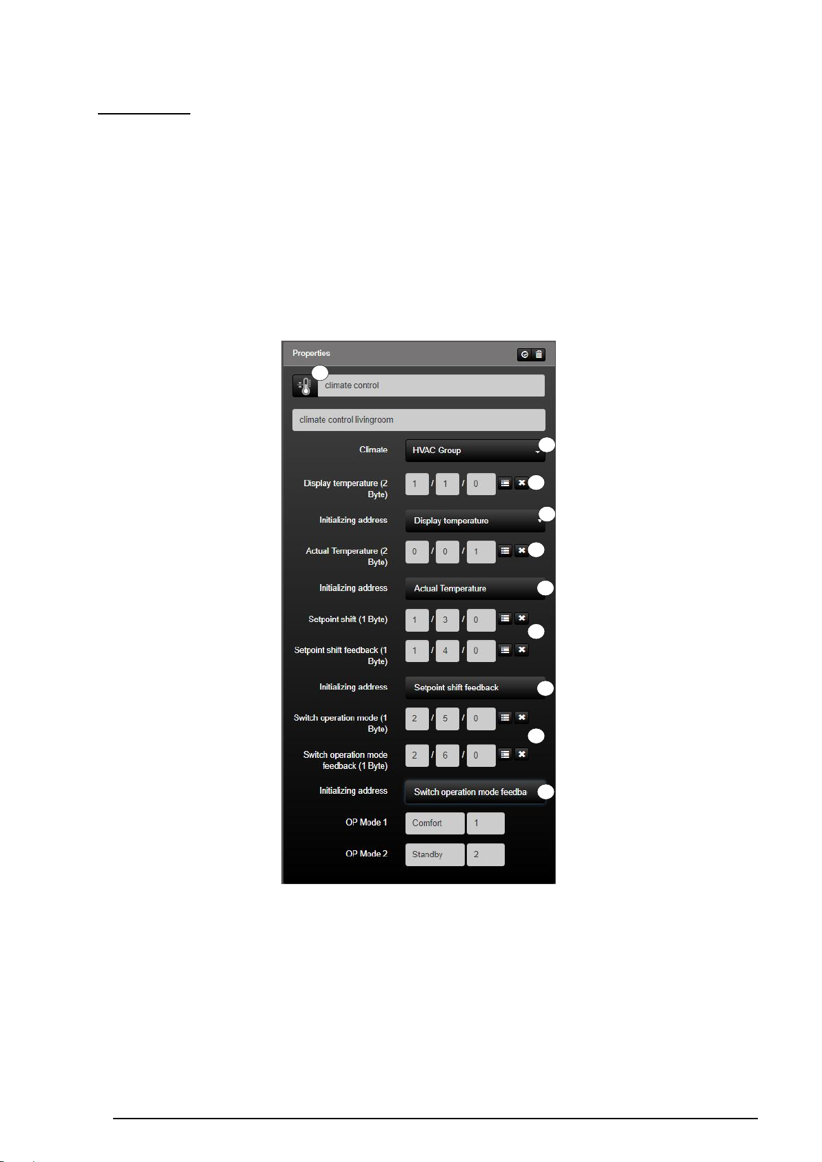
HVAC Group:
With the function "function group HVAC" (1) an all-embracing KNX climate control can be
initiated. The current setpoint temperature is indicated by the group address "setpoint
temperature display" (2) depending on the set operating mode. The group address "actual
temperature" (3) shows the values rounded to one decimal place. The sending and reading
of the current setpoint shift (4) can be configured by the corresponding addresses. The
current operating mode can be changed and read out by the group addresses "operating
mode switchover" or "operating mode feedback signal" (5).
In addition, by declaring four initialization addresses (6) during system startup, the current
status of the function can be queried.
Figure 36: Display of the "HVAC Group" function
Page 59
SV-SERVER-01 / SV-SERVER-INT 58 / 157
KNX-Funktion
Auswahl der Symbol-Bibliothek
im SV-Control
Bedien- und Anzeigeelement
in der SV-Home
HVAC group
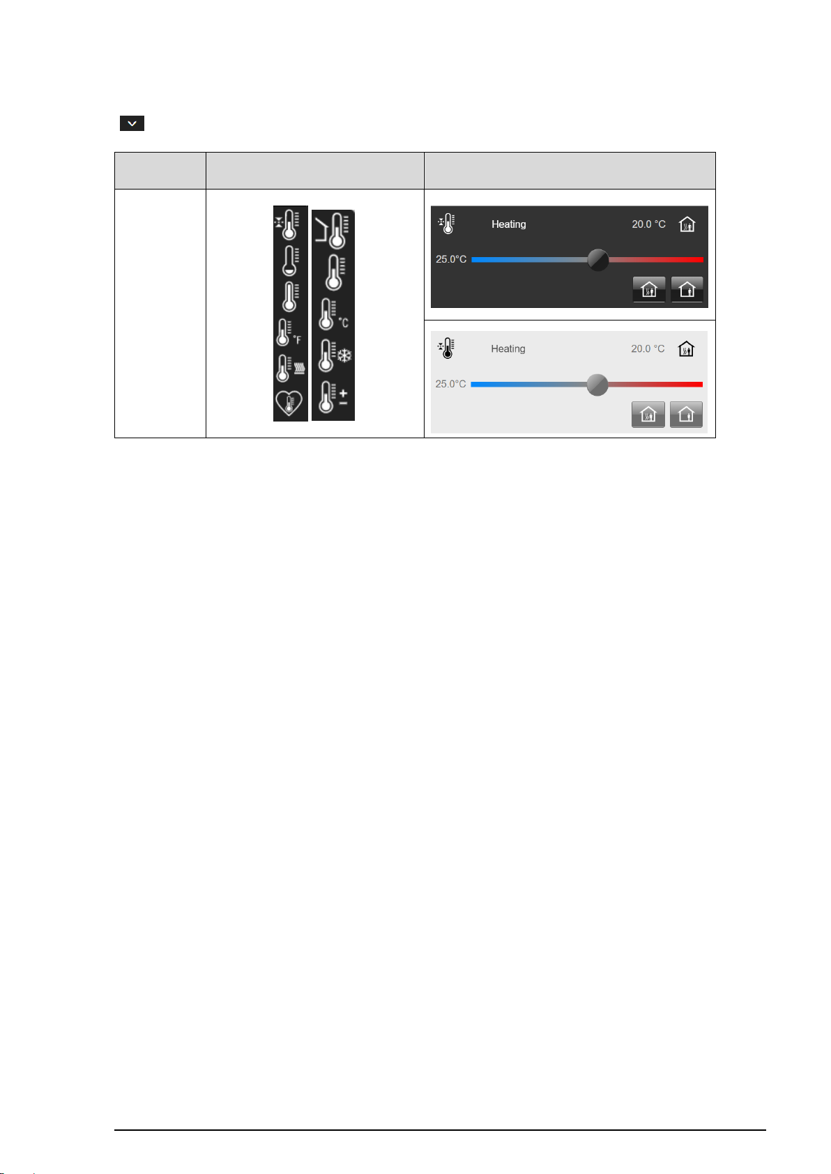
The function has favorites within the symbol library (7). Additional icons are available via the
" " button.
Table 18: Display of the „HVAC“ function
Page 60
SV-SERVER-01 / SV-SERVER-INT 59 / 157
1
2 3 4
5 6 8
7
10
9
Multimedia
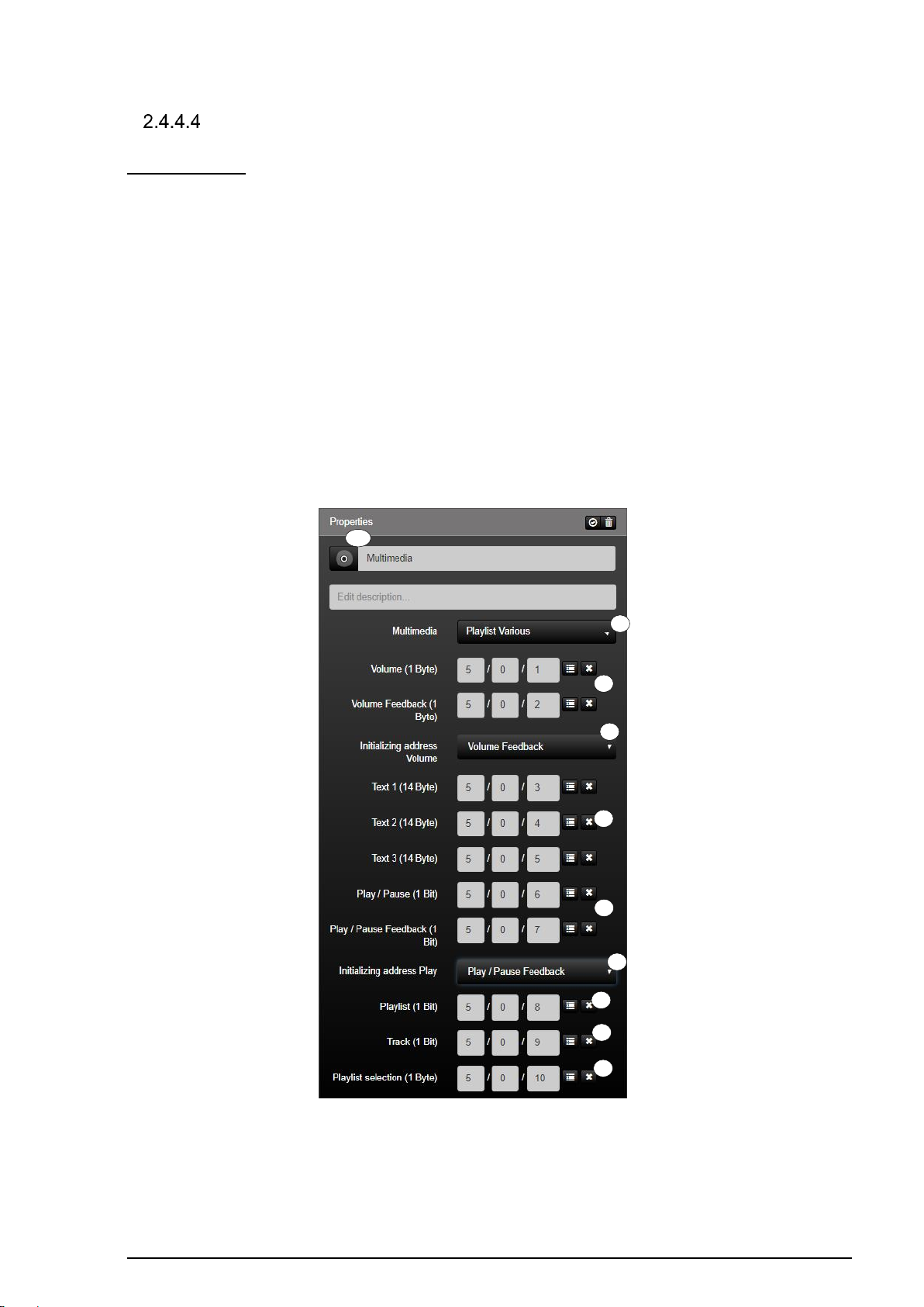
Playlist various:
The "Playlist divers (1)" function is the KNX function for controlling simple multimedia
applications.
The volume can be influenced and confirmed by the group addresses "volume" or "volume
feedback" (2).
In the input fields (3) the function can read ASCII characters of the registered group
addresses (for example, playlist, artist, title). If a text is written to these group addresses,
these are visible in the SV home.
Furthermore, another playlist (5) or title (6) can be jumped to and another playlist (7) can be
selected.
In addition, by declaring two initialization addresses (8-9) during system startup, the current
status of the function can be queried.
Figure 37: Function „Playlist Various“
Page 61
SV-SERVER-01 / SV-SERVER-INT 60 / 157
KNX function
Selection of the icon library in SV-Control
Operating and display element in SV-Home
Playlist Various
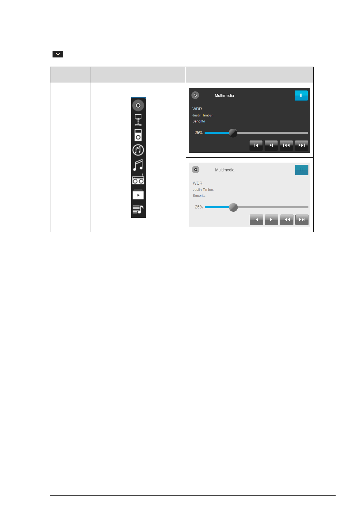
The function has favorites within the symbol library (8). Additional icons are available via the
" " button.
Table 19: Display of the „Playlist various“ function
Page 62

SV-SERVER-01 / SV-SERVER-INT 61 / 157
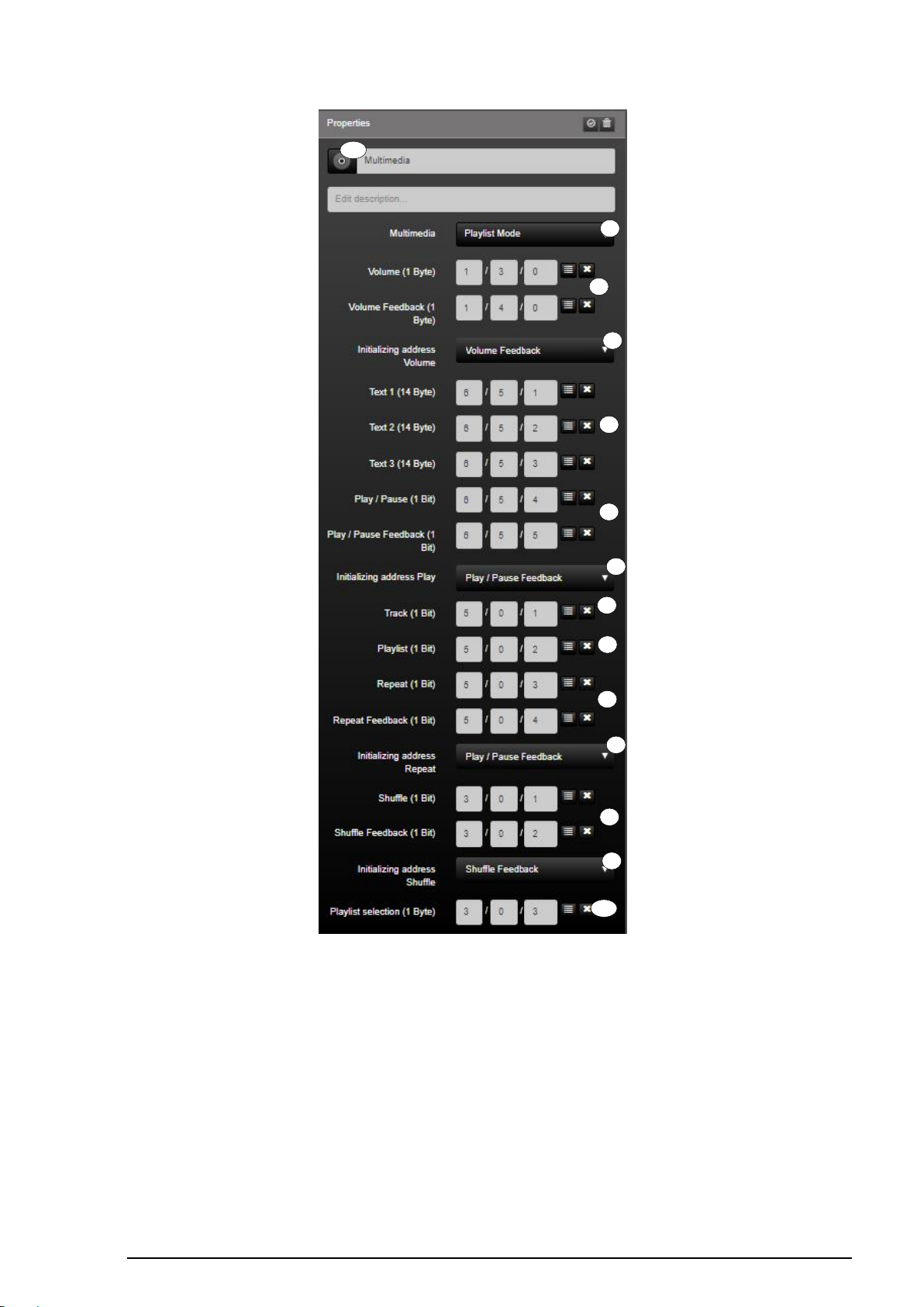
Playlist Mode:
The "Playlist mode (1)" function is the KNX function for comprehensive control of multimedia
applications.
The volume can be influenced and confirmed by the group addresses "volume" or "volume
feedback" (2).
In the input fields (3) the function can read ASCII characters of the registered group
addresses (for example, playlist, artist, title). If a text is written to these group addresses in
the KNX system, these are visible in the SV home.
Playback can be influenced and confirmed by the group addresses "Play / Pause" or "Play
/ Pause Confirmation" (4). Furthermore, a further playlist (5) or title (6) can be started.
The function has the possibility to play the current playlist in a loop (7) or randomly (8).
The function "Playlist selection" (10) can be used to select another playlist.
In addition, by declaring two initialization addresses (9) during system startup, the current
status of the function can be queried.
Page 63
SV-SERVER-01 / SV-SERVER-INT 62 / 157
1 2 3 4 5 6 7
8 9 9 9 9
10
11
Figure 38: Function „Playlist Mode“
Page 64
SV-SERVER-01 / SV-SERVER-INT 63 / 157
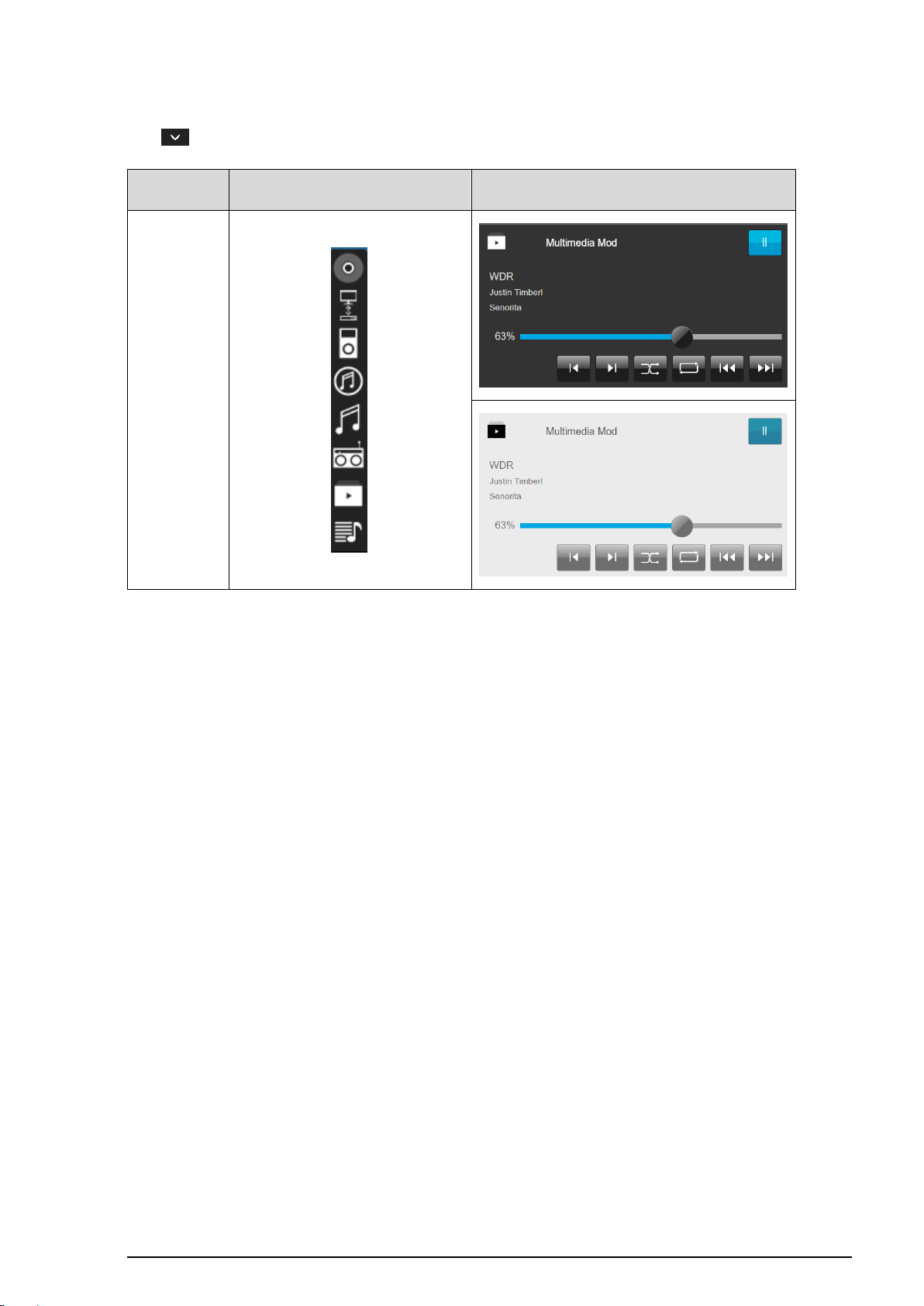
KNX function
Selection of the icon library in SV-Control
Operating and display element in SV-Home
Playlist Mode
The function has favorites within the symbol library (11). Additional icons are available via
the " " button.
Table 20: Display of the "Playlist Mode" function
Page 65
SV-SERVER-01 / SV-SERVER-INT 64 / 157
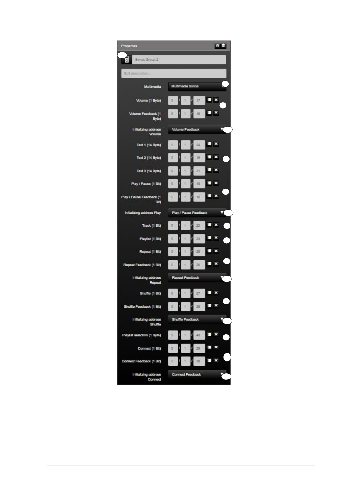
Multimedia Sonos:
The "Multimedia Sonos (1)" function is the KNX function for comprehensive control of
multimedia applications.
The volume can be influenced and confirmed by the group addresses "volume" or "volume
feedback" (2).
In the input fields (3) the function can read ASCII characters of the registered group
addresses (for example, playlist, artist, title). If a text is written to these group addresses in
the KNX system, these are visible in the SV home.
Playback can be influenced and confirmed by the group addresses "Play / Pause" or "Play
/ Pause Confirmation" (4). Furthermore, a further playlist (5) or title (6) can be started.
The function has the possibility to play the current playlist in a loop (7) or randomly (8).
In addition, by declaring two initialization addresses (9) during system startup, the current
status of the function can be queried.
You can play different playlists via the "Playlist" group address (9). For this purpose, sonos
loudspeakers can be connected and decoupled by means of the group addresses "connect"
or "connect feedback" (10).
In addition, by declaring two initialization addresses (12) during system startup, the current
status of the function can be queried.
Page 66
SV-SERVER-01 / SV-SERVER-INT 65 / 157
1 2 9
12
10
8 7 6 5 4 3 11
12
12
12
12
Figure 39: Function „Multimedia Sonos“
Page 67
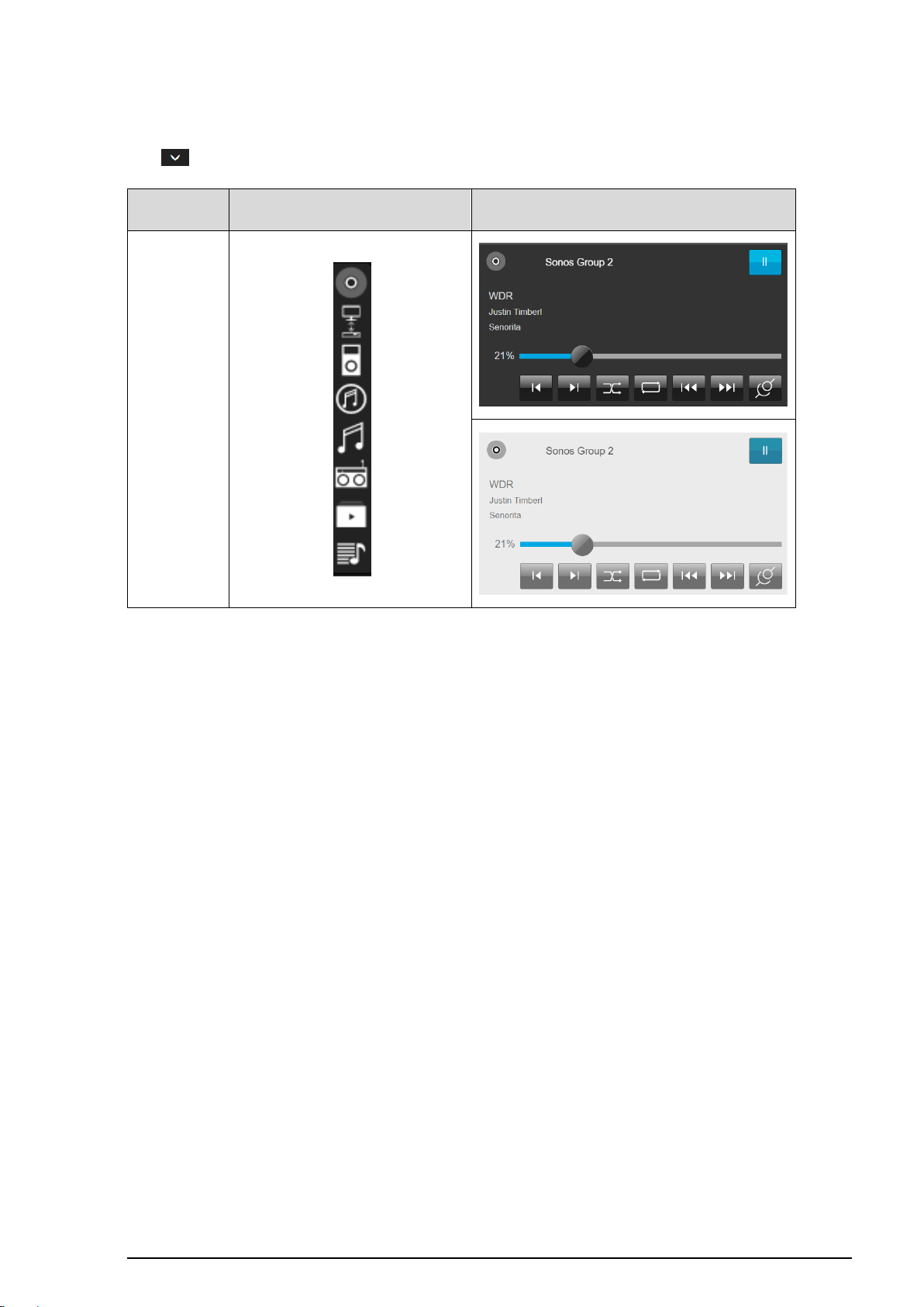
SV-SERVER-01 / SV-SERVER-INT 66 / 157
KNX function
Selection of the icon library in SV-Control
Operating and display element in SV-Home
Multimedia
Sonos
The function has favorites within the symbol library (11). Additional icons are available via
the " " button.
Table 21: Display of the "Multimedia Sonos" function
Page 68
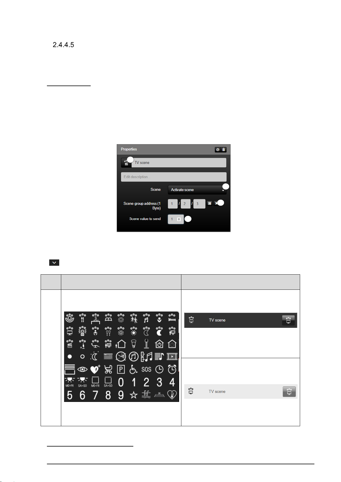
SV-SERVER-01 / SV-SERVER-INT 67 / 157
KNX
function
Selection of the icon library in SV-Control
Operating and display element in SV-Home
Activat
e
Scene
1 2 3
4
Scene
The Smart Visu Server supports the execution and learning of KNX function values. If
required, the function type "Scene" can be depicted by two differentiated KNX functions.
Activate Scene:
The "Activate Scene" function (1) is a Smart Visu Server function for executing KNX scenes.
The function transmits a scene value (2) to the KNX group address entered in the input field
"Scene group address (1 Byte)" (3). With each KNX scene group address, up to 64 scene
values (or scene numbers) (2) can be recalled. The scene value (2) the Smart Visu Server
should transmit when a scene is triggered can be set in the input field (2).
Figure 40: Parameters of the "Activate scene" function
The function has favorites within the symbol library (4). Additional icons are available via the
" " button.
Table 22: Display of the "Activate scene" function
Activate & Learn Scene (KNX):
Page 69
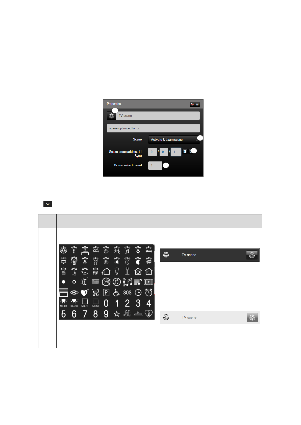
SV-SERVER-01 / SV-SERVER-INT 68 / 157
KNX
function
Selection of the icon library in SV-Control
Operating and display element in SV-Home
Activate
& learn
scene
1
2 2 4
The "Activate and Learn Scene (KNX)" function (1) is a Smart Visu Server function for
executing KNX scenes. This is currently only with a terminal (PC or similar) including mouse
usable.
The function transmits a scene value (2) to the KNX group address entered in the input field
"Scene group address (1 Byte)" (3). With each KNX scene group address, up to 64 scene
values (or scene numbers) (2) can be recalled. The scene value (2) the Smart Visu Server
should transmit when a scene is triggered can be set in the input field (2).
Figure 41: Parameters of the "Activate and learn" function
The function has favorites within the symbol library (4). Additional icons are available via the
" " button.
Table 23: Display of the "Activate & learn scene" function
Page 70
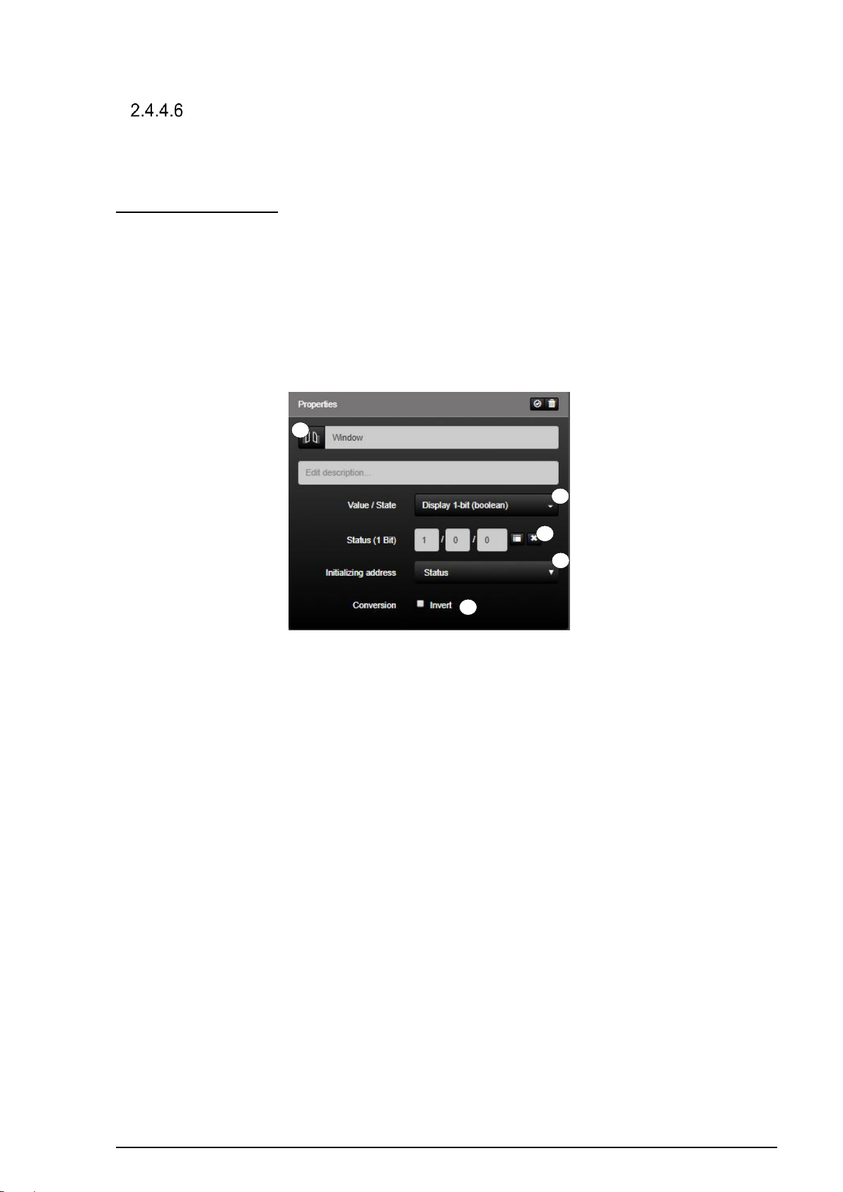
SV-SERVER-01 / SV-SERVER-INT 69 / 157
1
2 3 4
5
Value / State
The function type "Value / Status" can optionally be mapped by 12 differentiated KNX
functions.
Display 1-Bit (boolean):
The function "Display 1-bit" (1) is the KNX function for displaying one-bit status values of the
KNX system.
The function reads the KNX group address entered in the input field "Status (1 Bit)" (2). In
addition, the current status of the function can be polled by defining two initialisation
addresses (3) on starting the system.
The value conversion (4) can be used to invert the result by pressing the check mark.
Figure 42: Parameters of the "Display 1-bit values" function
Page 71
SV-SERVER-01 / SV-SERVER-INT 70 / 157
KNX function
Selection of the icon library in SV-Control
Operating and display element in SV-Home
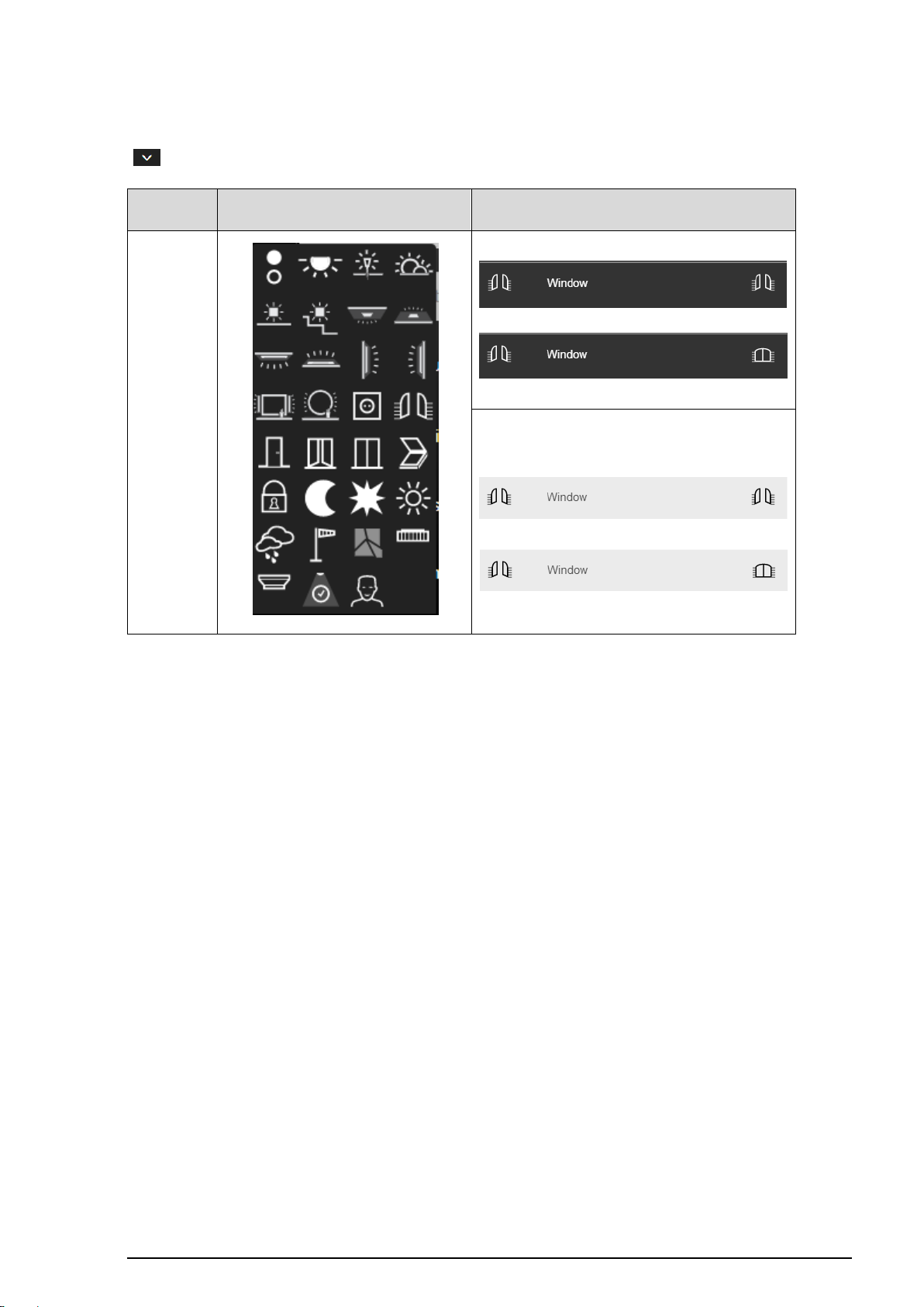
Display 1-bit
The function has favorites within the symbol library (5). Additional icons are available via the
" " button.
Table 24: Display of the "Display 1 Bit" function
Page 72
SV-SERVER-01 / SV-SERVER-INT 71 / 157
KNX function
Selection of the icon library in SV-Control
Operating and display element in SV-Home
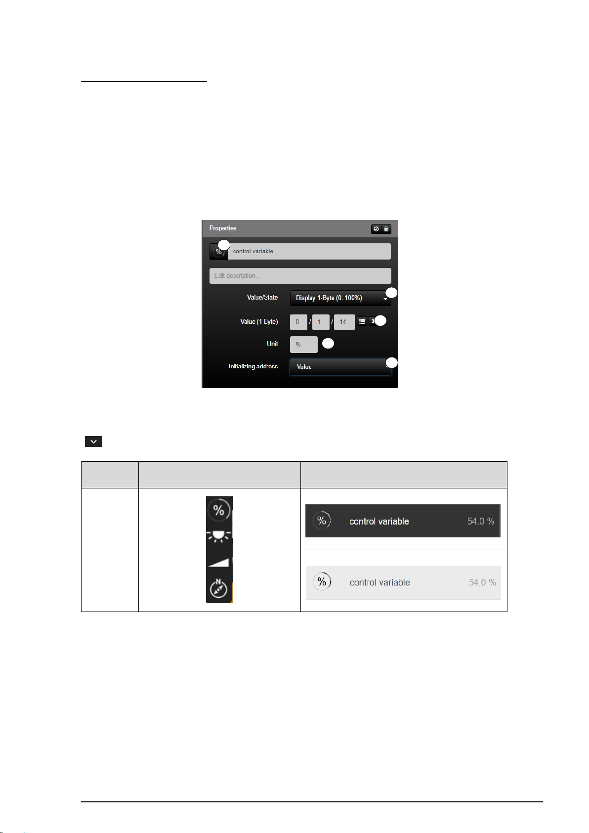
Display 1 Byte
(0 ..100%)
1 2 3 4 5
Display 1 Byte (0 ..100%):
The function "Display 1-Byte" (1) is the KNX function for displaying one-bit integer values
(0...100%) in SV-Home.
The function reads the KNX group address entered in the input field "Values (1 Byte)" (2).
As values can be sent without a unit in the KNX system, the input field "Unit" (3) can be used
to enter an individual unit, which is added to the numerical value in the visualisation.
In addition, the current status of the function can be polled by defining two initialisation
addresses (4) on starting the system.
Figure 43: Parameters of the "Display 1-byte" function
The function has favorites within the symbol library (5). Additional icons are available via the
" " button.
Table 25: Display of the "Display 1-Byte" function
Page 73
SV-SERVER-01 / SV-SERVER-INT 72 / 157
KNX function
Selection of the icon library in SV-Control
Operating and display element in SV-Home
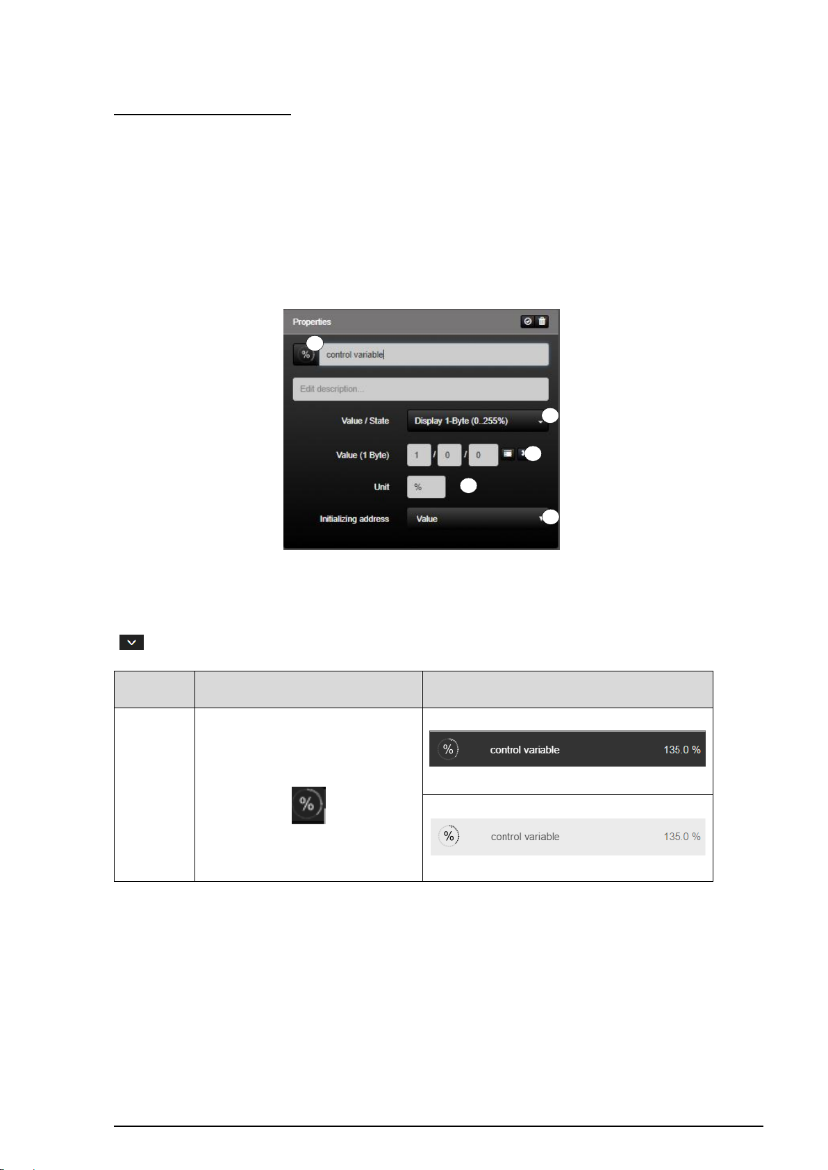
Display 1 Byte
(0 ..255%)
1 2 3 4 5
Display 1 Byte (0 ..255%):
The function "Display 1-Byte" (1) is the KNX function for displaying one-bit integer values
(0...255%) in SV-Home.
The function reads the KNX group address entered in the input field "Values (1 Byte)" (2).
As values can be sent without a unit in the KNX system, the input field "Unit" (3) can be used
to enter an individual unit, which is added to the numerical value in the visualisation.
In addition, the current status of the function can be polled by defining two initialisation
addresses (4) on starting the system.
Figure 44: Parameters of the "Display 1-byte (0..255%)" function
The function has favorites within the symbol library (5). Additional icons are available via the
" " button.
Table 26: Display of the "Display 1-Byte (0..255%)" function
Page 74
SV-SERVER-01 / SV-SERVER-INT 73 / 157
KNX function
Selection of the icon library in SV-Control
Operating and display element in SV-Home
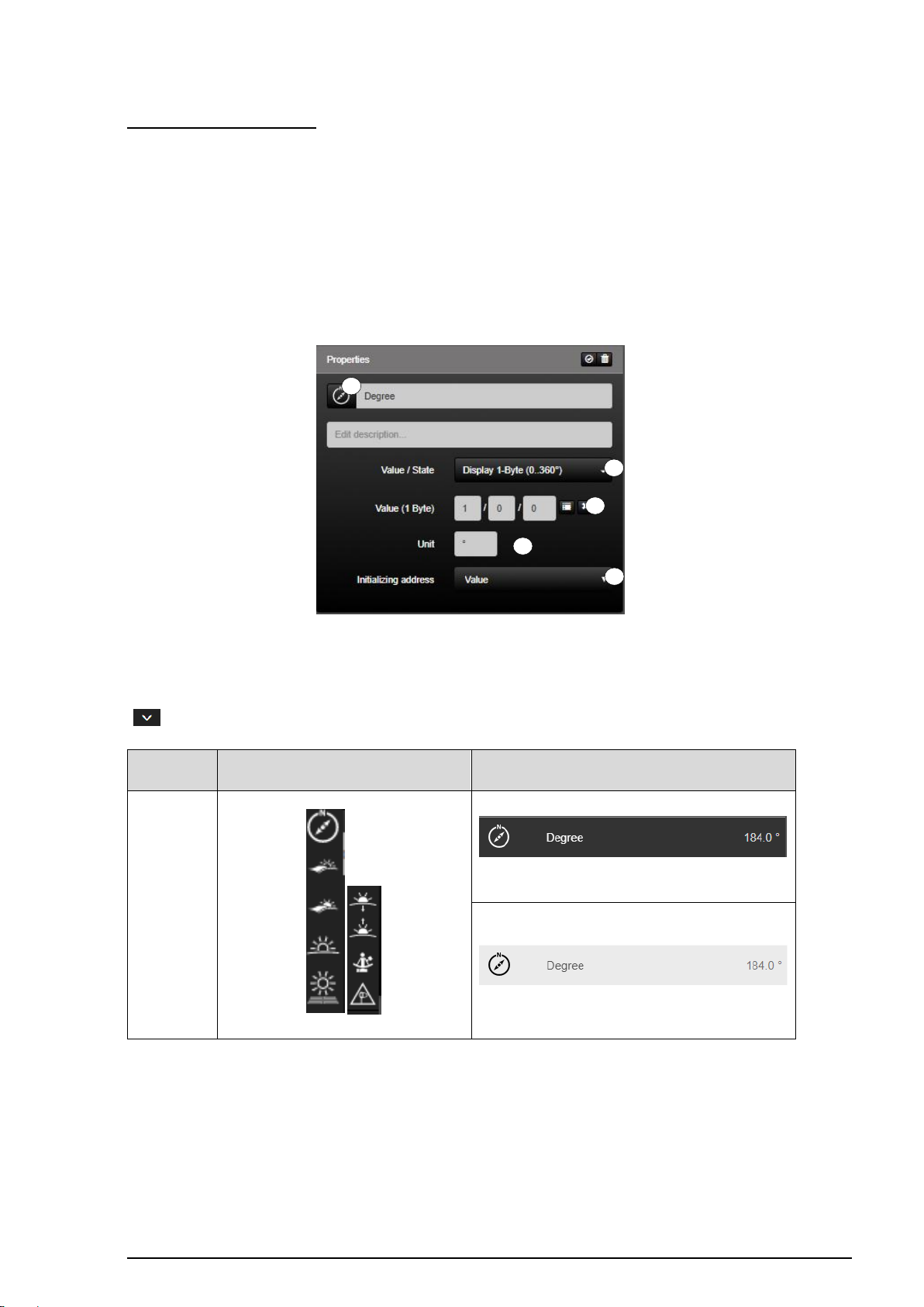
Display 1 Byte
(0 ..360°)
1 2 3 4 5
Display 1 Byte (0 ..360°):
The function "Display 1-Byte" (1) is the KNX function for displaying one-bit integer values
(0...306°) in SV-Home.
The function reads the KNX group address entered in the input field "Values (1 Byte)" (2).
As values can be sent without a unit in the KNX system, the input field "Unit" (3) can be used
to enter an individual unit, which is added to the numerical value in the visualisation.
In addition, the current status of the function can be polled by defining two initialisation
addresses (4) on starting the system.
Figure 45: Parameters of the "Display 1-byte (0..360°)" function
The function has favorites within the symbol library (5). Additional icons are available via the
" " button.
Table 27: Display of the "Display 1-Byte (0..360°)" function
Page 75
SV-SERVER-01 / SV-SERVER-INT 74 / 157
1
2 3 4 5 6
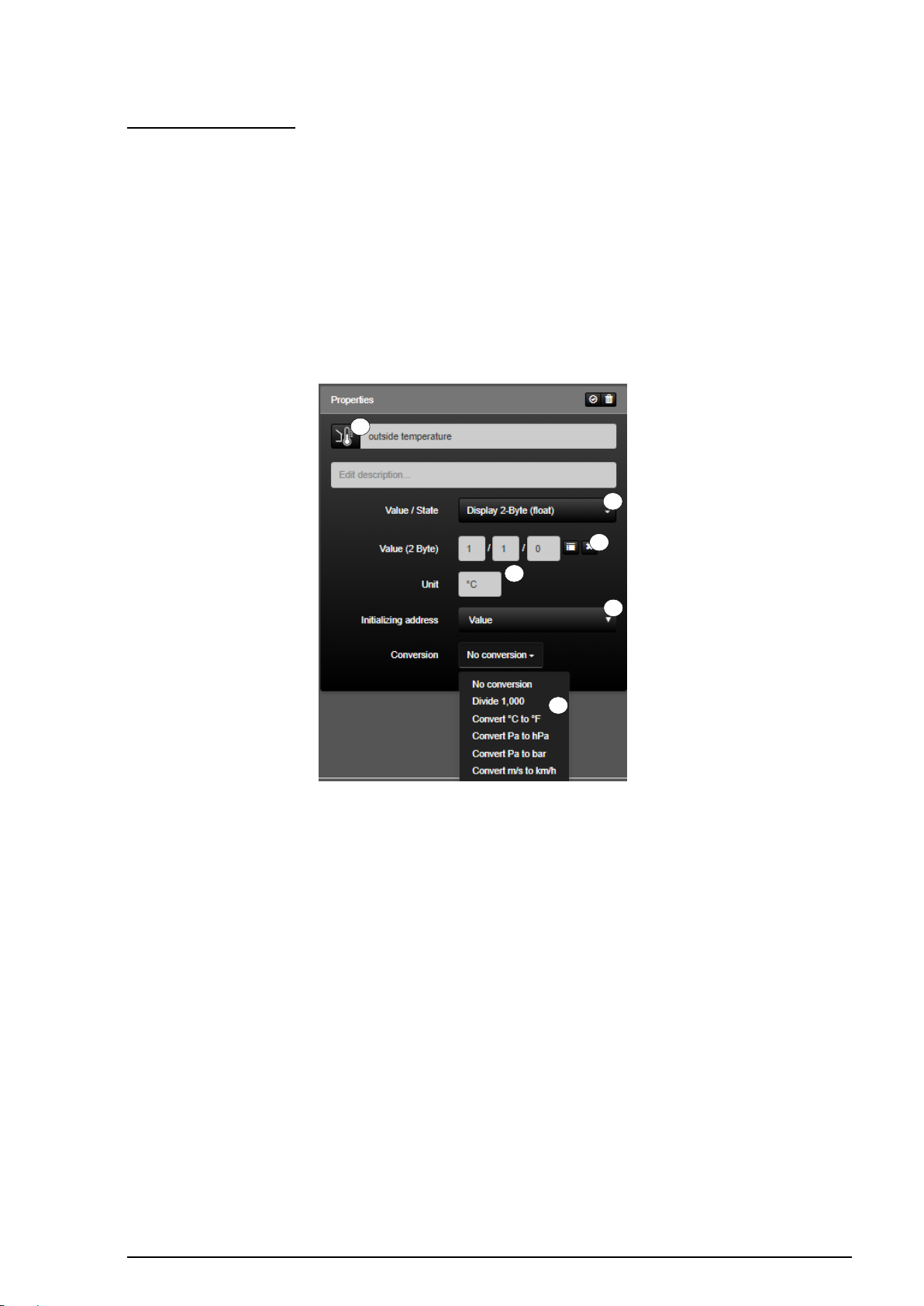
Display 2 Byte (Float):
The function "Display 2-Byte" (1) is the KNX function for displaying KNX two-bit values
(floating) in SV-Home. The displayed values are rounded down to the first decimal place.
The function reads the KNX group address entered in the input field "Values (2 Byte)" (2).
As only values can be sent without a unit in the KNX system, the input field "Unit" (3) can be
used to enter an individual unit, which is added to the numerical value in the visualisation.
In addition, the current status of the function can be polled by defining two initialisation
addresses (4) on starting the system.
With the value conversion (5), predefined units can be internally converted to another unit.
Figure 46: Parameters of the "Display 2-byte (Float)" function
Page 76
SV-SERVER-01 / SV-SERVER-INT 75 / 157
KNX function
Selection of the icon library in SV-Control
Operating and display element in SV-Home
Display 2-Byte
(Float)
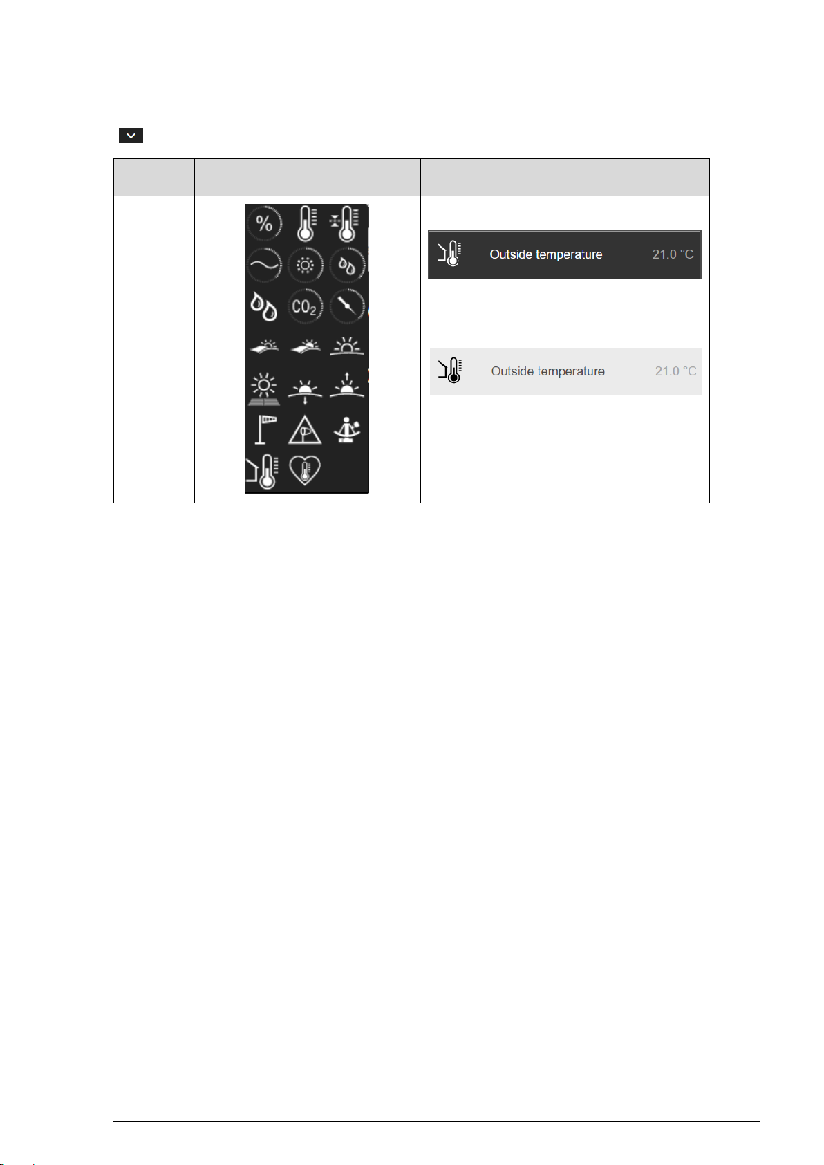
The function has favorites within the symbol library (6). Additional icons are available via the
" " button.
Table 28: Display of the "Display 2-Byte (Float)" function
Page 77
SV-SERVER-01 / SV-SERVER-INT 76 / 157
KNX function
Selection of the icon library in SV-Control
Operating and display element in SV-Home
Display 2-Byte
(Lux)
1
2 3 4 5 6
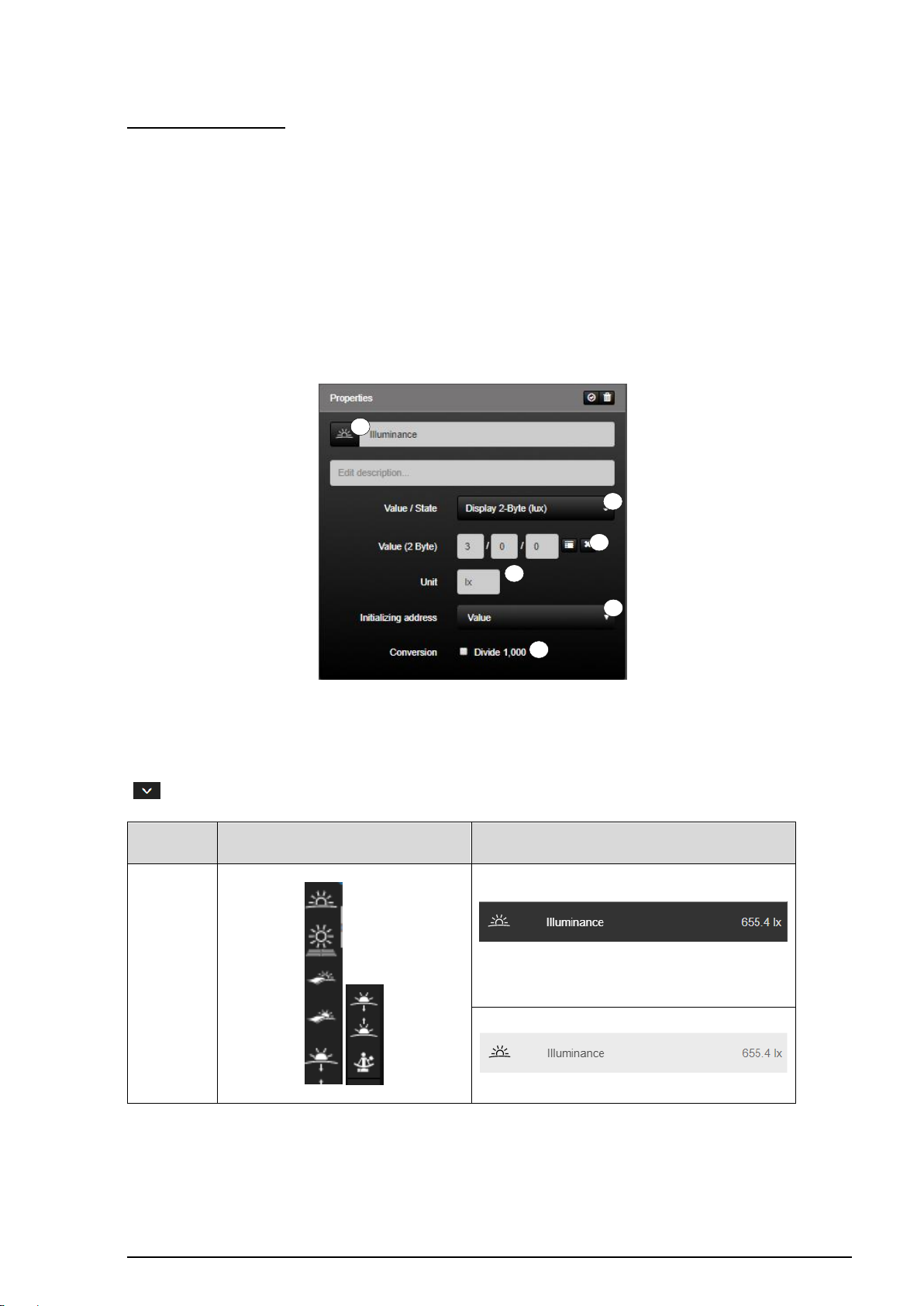
Display 2 Byte (Lux):
The function "Display 2-Byte (Lux)" (1) is the KNX function for displaying KNX two-bit values
(floating) in SV-Home. The displayed values are rounded down to the first decimal place.
The function reads the KNX group address entered in the input field "Value (2 Byte)" (2). As
only values can be sent without a unit in the KNX system, the input field "Unit" (3) can be
used to enter an individual unit, which is added to the numerical value in the visualisation.
In addition, the current status of the function can be polled by defining two initialisation
addresses (4) on starting the system.
The value conversion (5) can be used to invert the result by pressing the check mark.
Figure 47: Parameters of the "Display 2-byte (Lux)" function
The function has favorites within the symbol library (6). Additional icons are available via the
" " button.
Table 29: Display of the "Display 2-Byte (Lux)" function
Page 78
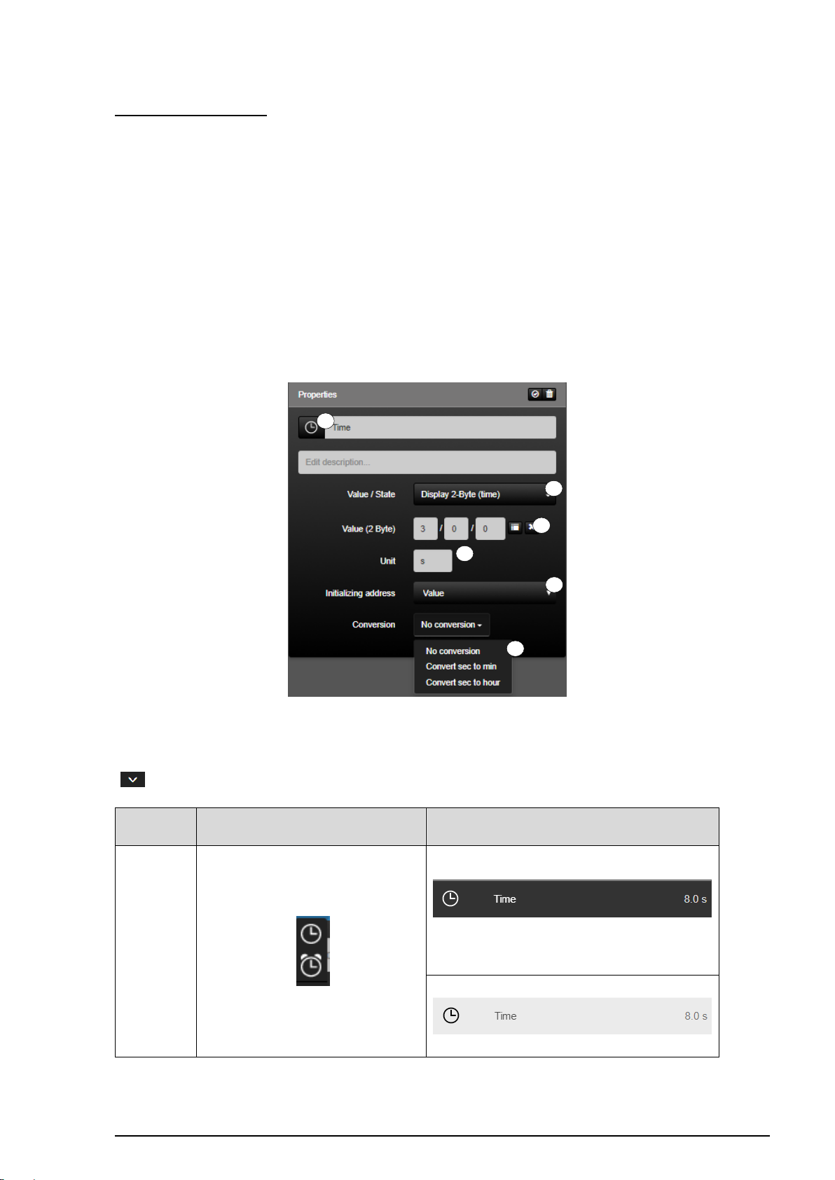
SV-SERVER-01 / SV-SERVER-INT 77 / 157
KNX function
Selection of the icon library in SV-Control
Operating and display element in SV-Home
Display 2-Byte
(Time)
1 2 3 4 5
6
Display 2 Byte (Time):
The function "Display 2-Byte (Time)" (1) is the KNX function for displaying KNX two-bit
values (floating) in SV-Home. The displayed values are rounded down to the first decimal
place.
The function reads the KNX group address entered in the input field "Value (2 Byte)" (2). As
only values can be sent without a unit in the KNX system, the input field "Unit" (3) can be
used to enter an individual unit, which is added to the numerical value in the visualisation.
In addition, the current status of the function can be polled by defining two initialisation
addresses (4) on starting the system.
The value conversion (5) can be used to convert the time of seconds into minutes or
hours.
Figure 48: Parameters of the "Display 2-byte (Time)" function
The function has favorites within the symbol library (6). Additional icons are available via the
" " button.
Table 30: Display of the "Display 2-Byte (Time)" function
Page 79
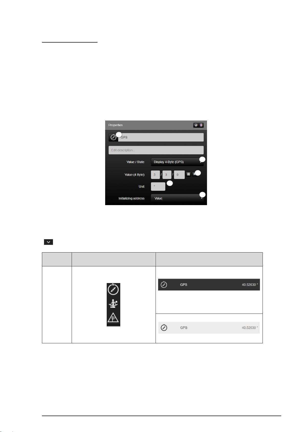
SV-SERVER-01 / SV-SERVER-INT 78 / 157
KNX function
Selection of the icon library in SV-Control
Operating and display element in SV-Home
Display 2-Byte
(Time)
1
2 3 4
5
Display 4 Byte (Time):
The function "Display 4-Byte (Time)" (1) is the KNX function for displaying KNX two-bit
values (floating) in SV-Home. The displayed values are rounded down to the first decimal
place.
The function reads the KNX group address entered in the input field "Value (4 Byte)" (2). As
only values can be sent without a unit in the KNX system, the input field "Unit" (3) can be
used to enter an individual unit, which is added to the numerical value in the visualisation.
In addition, the current status of the function can be polled by defining two initialisation
addresses (4) on starting the system.
Figure 49: Parameters of the "Display 4-byte (GPS)" function
The function has favorites within the symbol library (5). Additional icons are available via the
" " button.
Table 31: Display of the "Display 4-Byte (GPS)" function
Page 80
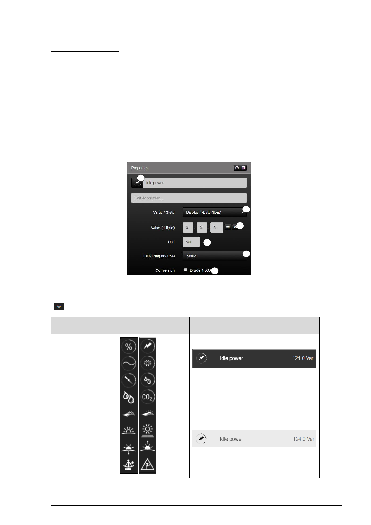
SV-SERVER-01 / SV-SERVER-INT 79 / 157
KNX function
Selection of the icon library in SV-Control
Operating and display element in SV-Home
Display 4 Byte
(Float)
1
2 3 4
5
6
Display 4 Byte (Float):
The function "Display 4-Byte (float)" (1) is the KNX function for displaying positive or negative
floating point values of the KNX system in SV-Home. The displayed values are rounded
down to the first decimal place.
The function reads the KNX group address entered in the input field "Values (4 Byte)" (2).
As values can be sent without a unit in the KNX system, the input field "Unit" (3) can be used
to enter an individual unit, which is added to the numerical value in the visualisation.
In addition, the current status of the function can be polled by defining two initialisation
addresses (4) on starting the system.
The value conversion (5) can be used to invert the result by pressing the check mark.
Figure 50: Parameters of the "Display 4-byte (Float)" function
The function has favorites within the symbol library (6). Additional icons are available via the
" " button.
Table 32: Display of the "Display 4 Byte (Float)" function
Page 81
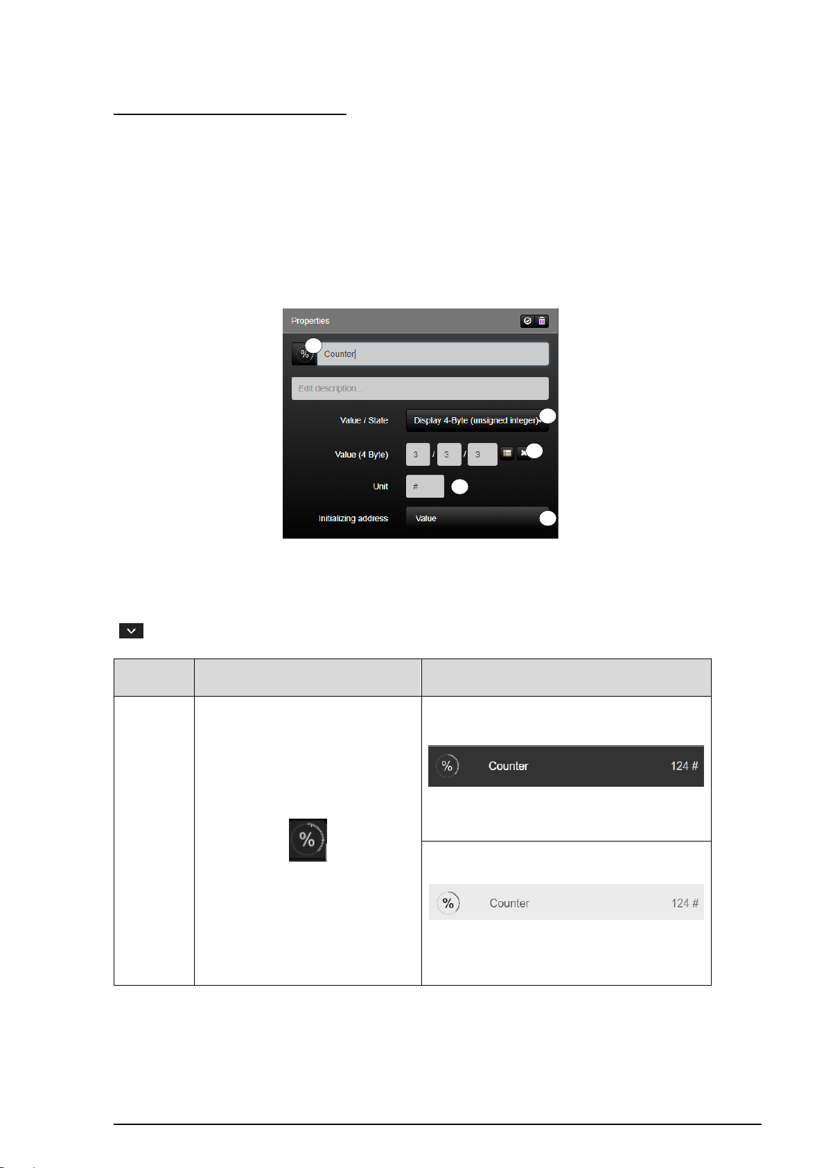
SV-SERVER-01 / SV-SERVER-INT 80 / 157
KNX function
Selection of the icon library in SV-Control
Operating and display element in SV-Home
Display 4 Byte
(Integer)
1 2 3 4 5
Display 4 Byte (Unsigned Integer):
The function "Display 4 Byte (Unsigned integer)" (1) is the KNX function for displaying
positive or negative integer values of the KNX system in SV-Home.
The function reads the KNX group address entered in the input field "Values (4 Byte)" (2).
As values can be sent without a unit in the KNX system, the input field "Unit" (3) can be used
to enter an individual unit, which is added to the numerical value in the visualisation.
In addition, the current status of the function can be polled by defining two initialisation
addresses (4) on starting the system.
Figure 51: Parameters of the "Display 4 byte (unsigned integer)" function
The function has favorites within the symbol library (5). Additional icons are available via the
" " button.
Table 33: Display of the "Display 4 Byte (unsigned integer)" function
Page 82
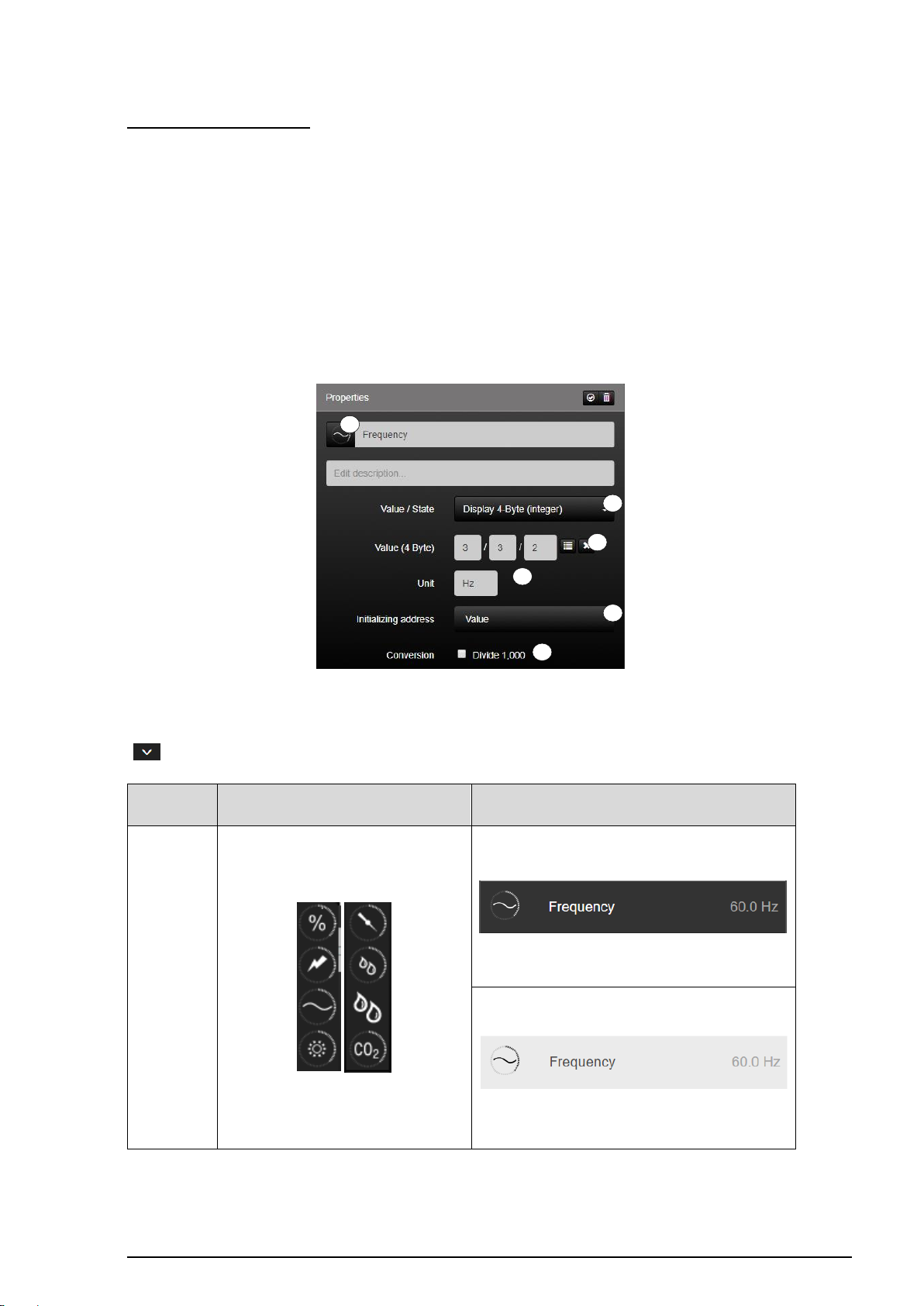
SV-SERVER-01 / SV-SERVER-INT 81 / 157
KNX function
Selection of the icon library in SV-Control
Operating and display element in SV-Home
Display 4 Byte
(Integer)
1
2
3
4
5
6
Display 4 Byte (Integer):
The function "Display 4 Byte (Integer)" (1) is the KNX function for displaying positive or
negative integer values of the KNX system in SV-Home.
The function reads the KNX group address entered in the input field "Values (4 Byte)" (2).
As values can be sent without a unit in the KNX system, the input field "Unit" (3) can be used
to enter an individual unit, which is added to the numerical value in the visualisation.
In addition, the current status of the function can be polled by defining two initialisation
addresses (4) on starting the system.
The value conversion (5) can be used to invert the result by pressing the check mark.
Figure 52: Parameters of the "Display 4 byte (integer)" function
The function has favorites within the symbol library (6). Additional icons are available via the
" " button.
Table 34: Display of the "Display 4 Byte (Integer)" function
Page 83
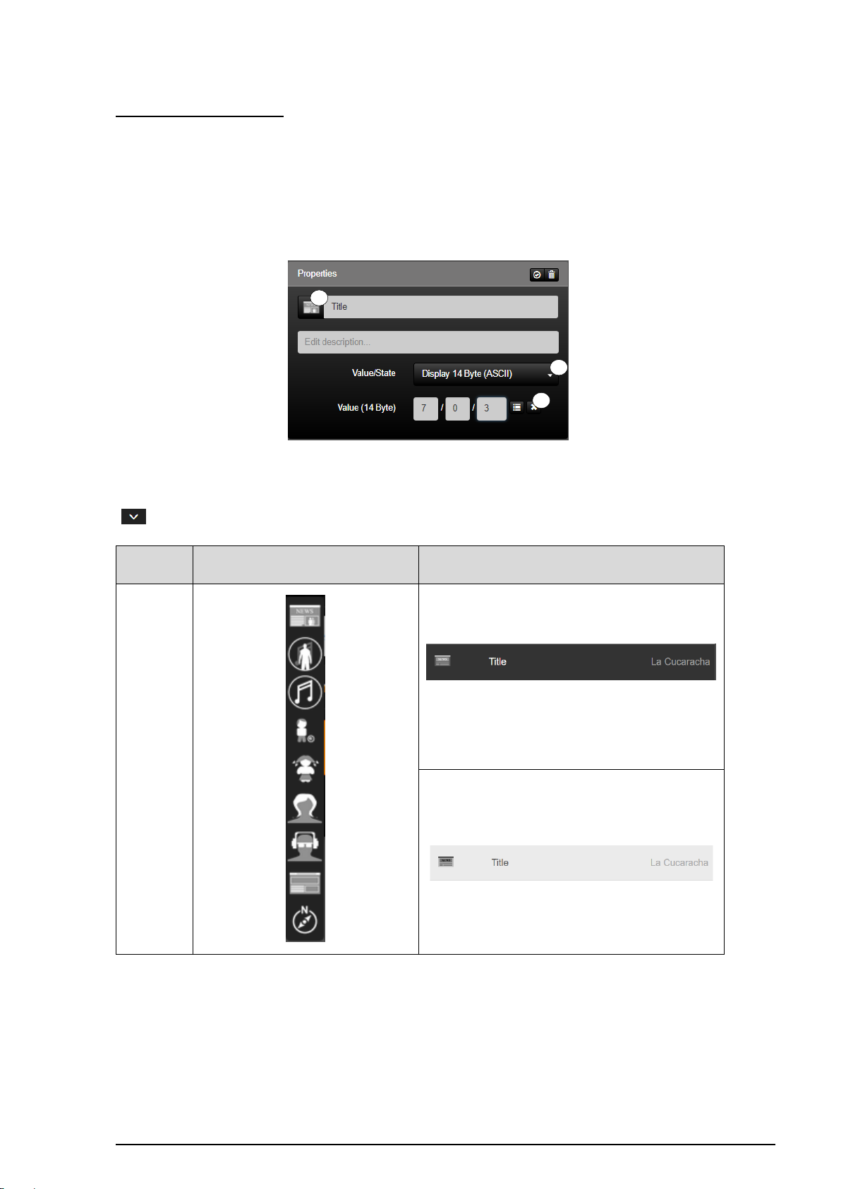
SV-SERVER-01 / SV-SERVER-INT 82 / 157
KNX function
Selection of the icon library in SV-Control
Operating and display element in SV-Home
14 Byte
(ASCII)
1 2 3
Display 14 Byte (ASCII):
The function "Display 14 Byte (ASCII)" (1) is the KNX function for displaying texts of a
maximum of 14 characters of the KNX system in SV-Home.
The function can read the ASCII characters in the group address entered in the input field
"Values (14 Byte)" (2). If a text is written to this group address in the KNX system, then this
can be displayed in SV-Home with this function.
Figure 53: Parameters of the "Display 14 byte (ASCII)" function
The function has favorites within the symbol library (3). Additional icons are available via the
" " button.
Table 35: Display of the "Display 14 Byte (ASCII)" function
Page 84
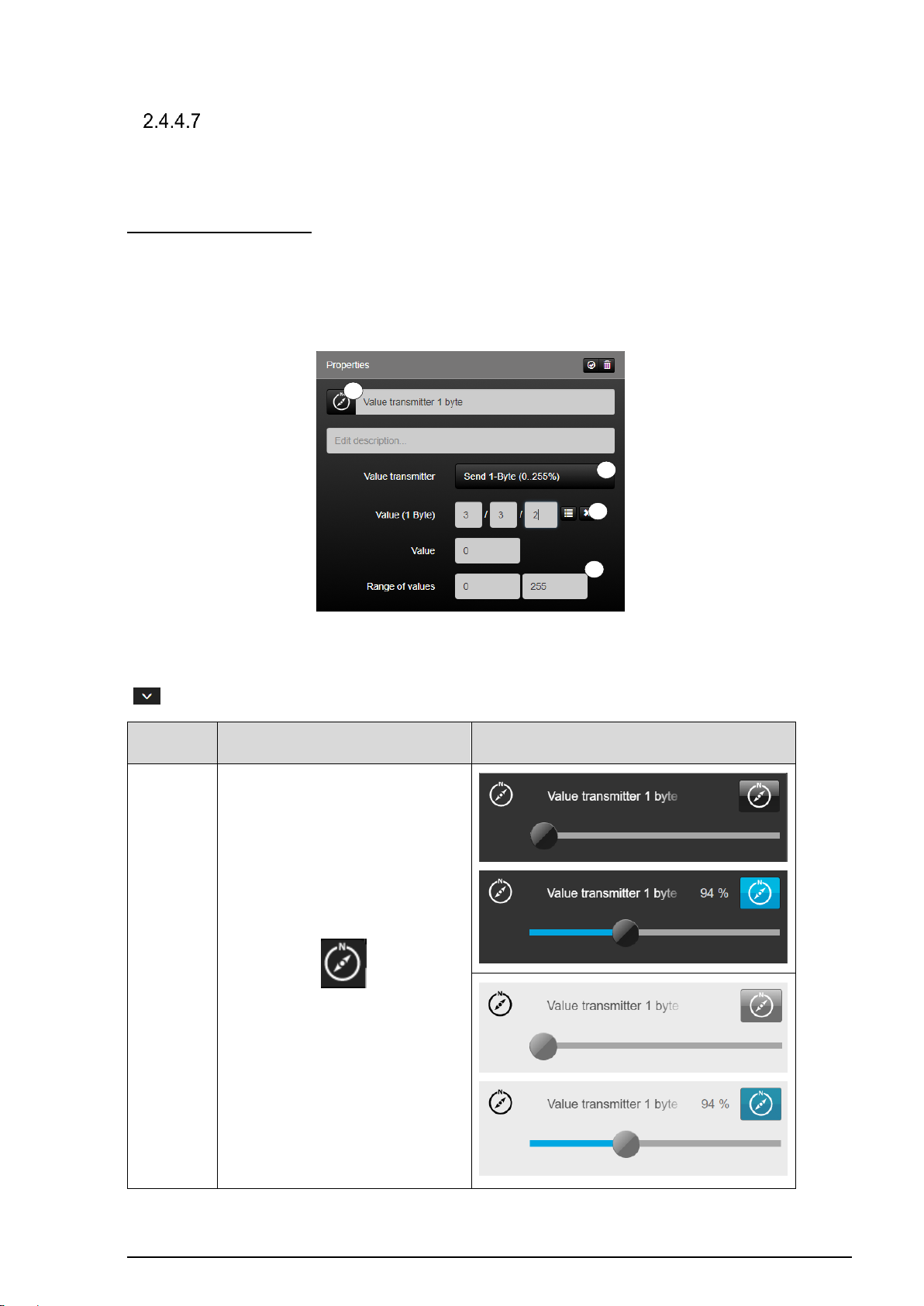
SV-SERVER-01 / SV-SERVER-INT 83 / 157
KNX-funktion
Selection of the icon library in SV-Control
Operating and display element in SV-Home
Send
1 byte
(0…255%)
1 2 3
4
Value transmitter
The function type "value transmitter" can optionally be represented by three differentiated
KNX functions.
Send 1 Byte (0…255%):
The function "Send 1 byte" (1) is the KNX function with which 1-byte percentage values can
be set. This is passed on via the group address "Value" (2).
In addition, a predefined value can be set via "Send value" and the range can be defined via
"Value range" (3).
Figure 54: Parameter of the “Send 1 byte (0...255%)“ function
The function has favorites within the symbol library (4). Additional icons are available via the
" " button.
Table 36: Display of the “Send 1 byte (0...255%)“ function
Page 85
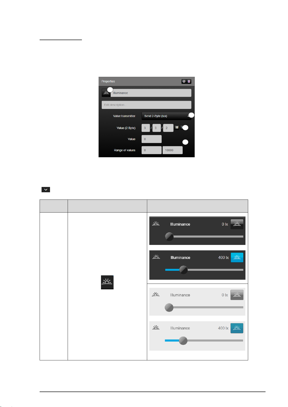
SV-SERVER-01 / SV-SERVER-INT 84 / 157
KNX-funktion
Selection of the icon library in SV-Control
Operating and display element in SV-Home
Send
2 byte
(0…99999)
1 2 3
4
Send 2 Byte (lux):
The function "Send 2 byte" (1) is the KNX function with which 2 byte lux values can be set.
This is passed on via the group address "Value" (2).
In addition, a predefined value can be set via "Send value" and the range can be defined via
"Value range" (3).
Figure 55: Parameter of the “Send 2 byte (lux)“ function
The function has favorites within the symbol library (4). Additional icons are available via the
" " button.
Table 37: Display of the “Send 2 byte (lux)“ function
Page 86
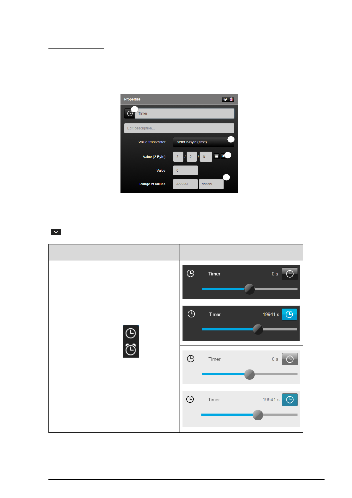
SV-SERVER-01 / SV-SERVER-INT 85 / 157
KNX-funktion
Selection of the icon library in SV-Control
Operating and display element in SV-Home
Send
1 byte
(-99999 -
99999)
1
2 3 4
Send 2 Byte (time):
The function "Send 2 byte" (1) is the KNX function with which 2 byte time values can be set.
This is passed on via the group address "Value" (2).
In addition, a predefined value can be set via "Send value" and the range can be defined via
"Value range" (3).
Figure 56: Parameter of the “Send 2 byte (time)“ function
The function has favorites within the symbol library (4). Additional icons are available via the
" " button.
Table 38: Display of the “Send 2 byte (time)“ function
Page 87
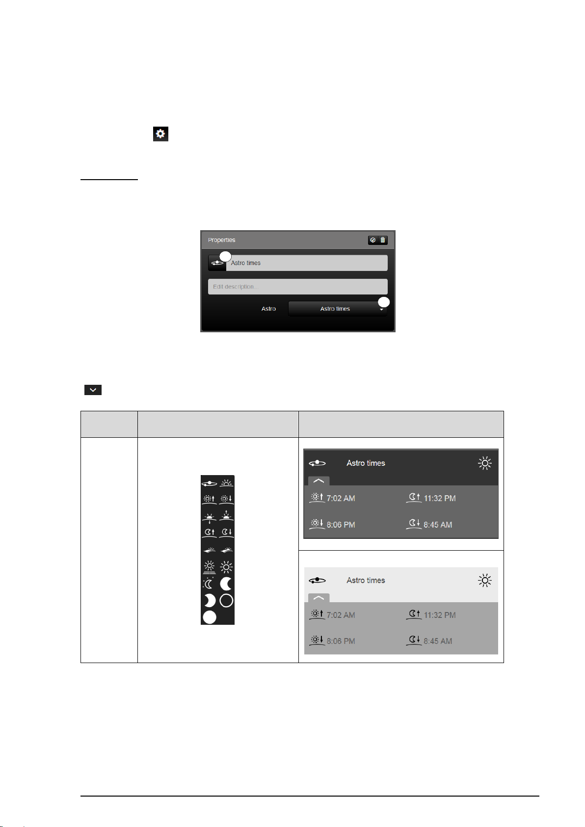
SV-SERVER-01 / SV-SERVER-INT 86 / 157
Function
Selection of the icon library in SV-Control
Operating and display element in SV-Home
Astro times
1
2
2.4.5 Astro
The function type "Astro" can optionally be mapped by nine differentiated functions. The
location coordinates (latitude and longitude) are stored under SV-Control configuration
management " " (chapter 2.6).
Astro times:
The function "Astro times" (1) displays the times for today's sunrise, sunset, moonrise and
moonset.
Figure 57: Parameter of the „Astro times“ function
The function has favorites within the symbol library (2). Additional icons are available via the
" " button.
Table 39: Display of the „Astro times“ function
Page 88
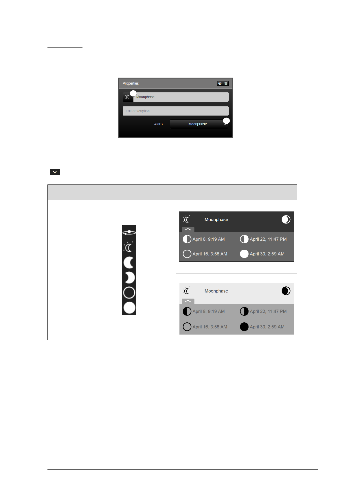
SV-SERVER-01 / SV-SERVER-INT 87 / 157
Function
Selection of the icon library in SV-Control
Operating and display element in SV-Home
Moonphase
1
2
Moonphase:
The function “Moonphase” (1) displays the different phases of the moon with the date and
time for the current month.
Figure 58: Parameter of the „Moonphase“ function
The function has favorites within the symbol library (2). Additional icons are available via the
" " button.
Table 40: Display of the „Moonphase“ function
Page 89
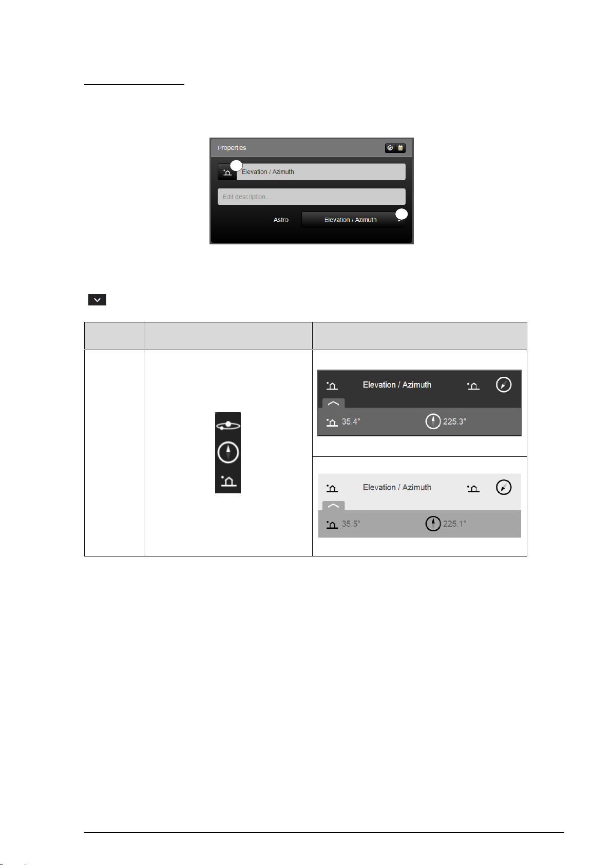
SV-SERVER-01 / SV-SERVER-INT 88 / 157
Function
Selection of the icon library in SV-Control
Operating and display element in SV-Home
Elevation /
Azimuth
1
2
Elevation / Azimuth:
The function "Elevation / Azimuth" (1) displays the current position of the sun (horizontal
and vertical) starting from the observation location.
Figure 59: Parameter of the „Elevation / Azimuth“ function
The function has favorites within the symbol library (2). Additional icons are available via the
" " button.
Table 41: Display of the „Elevation / Azimuth“ function
Page 90
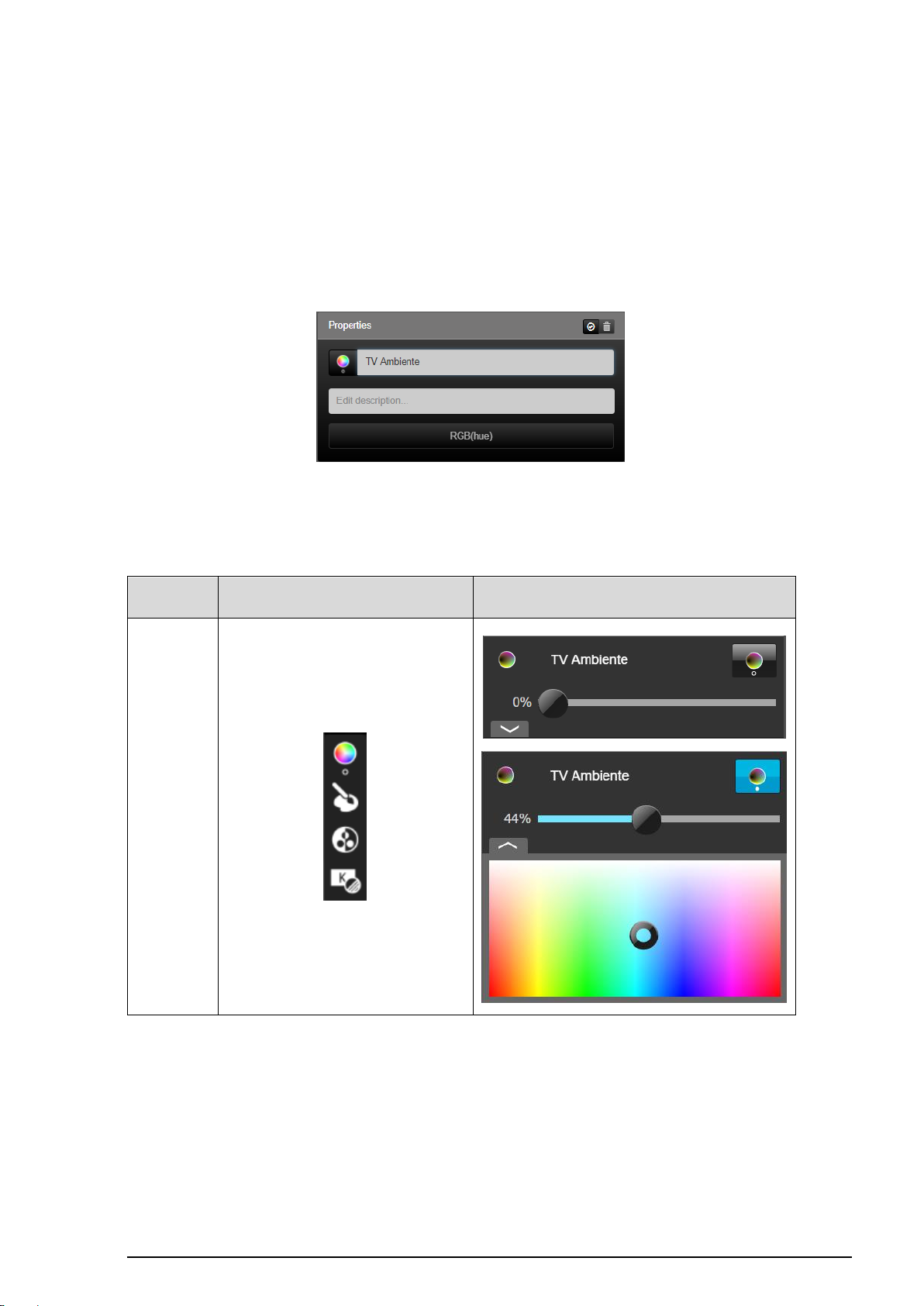
SV-SERVER-01 / SV-SERVER-INT 89 / 157
Hue lamps
Selection of the icon library in SV-Control
Operating and display element in SV-Home
RGB
(Hue)
2.4.6 Configuring Philips Hue functions
Successful commissioning and authentication of the Philips Hue System is required to be
able to use hue functions. The "User" and the "Administrator" have identical access rights
to Hue functions within the "Functions" column.
The Hue luminaires added to the SV-Server in the "Hue" tab are automatically supplemented
with their name in the function list (for information on Hue setup, please consult Chapter 2.3
”Hue").
Figure 60: Parameters of the "RGB (Hue)" function
In the "Areas & Functions" tab, no further function parameters of the Hue lamps can be
edited, with the exception of the icon, the function name and the function description.
Page 91
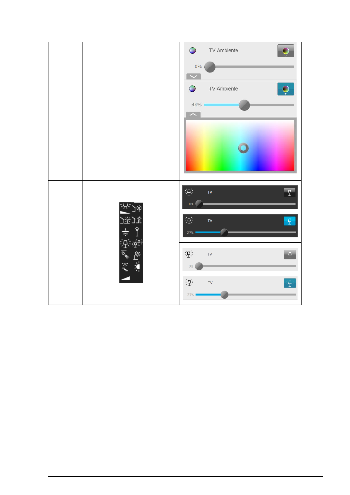
SV-SERVER-01 / SV-SERVER-INT 90 / 157
Dimming
(Hue white)
Table 42: Display of the "RGB (Hue)" and “Dimming (White) function
Page 92
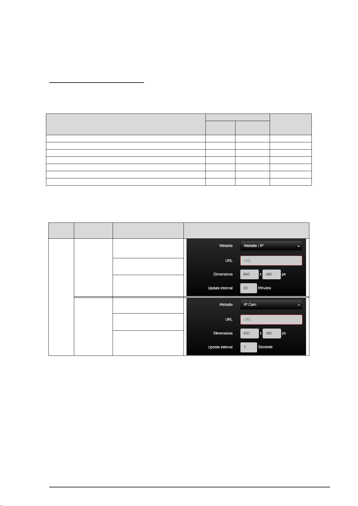
SV-SERVER-01 / SV-SERVER-INT 91 / 157
Access
User
Administrator
Areas &
Function
Web
Create Web functions
Edit names of Web functions
Edit icons of Web functions
Assign existing Web functions to new areas
Delete existing Web functions from areas
Change Web address, Web page size or update interval
Delete existing Web functions completely
Function
type
KNX function
Settable options
Depiction in SV-Control
Web
Website
URL
Size depiction
Update interval [in Sec]
IP camera
URL
Size depiction
Update interval [in Sec]
2.4.7 Configuring websites / IP functions
For web functions to be used, an Internet connection is required (except local IP cameras).
Access as Administrator or User
The "User" and the "Administrator" have different access rights to the web functions within
the "Functions" column.
Table 43: Access rights to the "Websites / IP" function group
The following two function types are available to the Administrator in SV-Control:
Table 44: Overview of the "Websites / IP" function group
Page 93
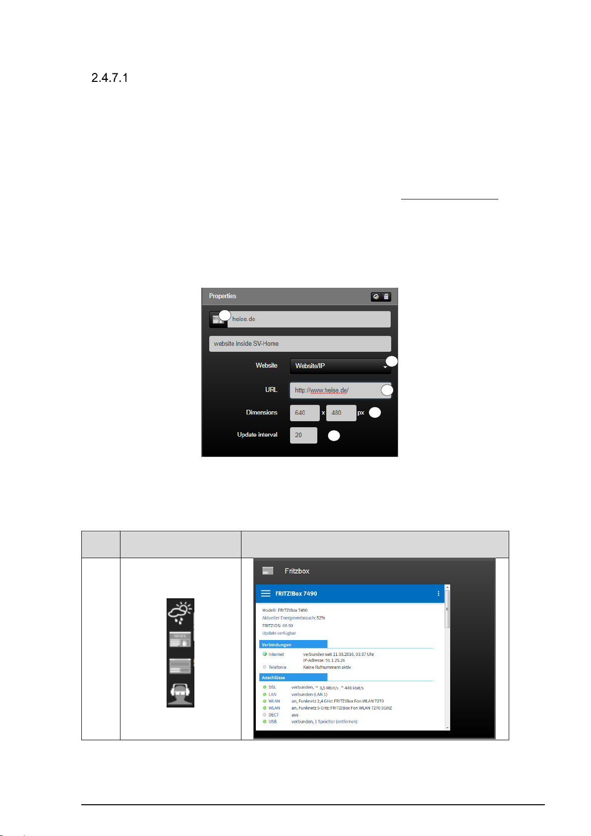
SV-SERVER-01 / SV-SERVER-INT 92 / 157
Website
/ IP
Selection of the icon library in SV-
Control
Operating and display element in SV-Home
Website
1 2 3 4 5
Websites
The "Website" function (1) can be used to integrate a website in SV-Home into selectable
areas. This function can be used, for example, to add your favourite weather forecasting
service to your building automation. In the same way, any other websites can be added to
the user interface of the SV-Home of your building automation.
The web address to be displayed can be entered in the "URL" input field (2). When making
an entry, ensure that your entry begins with http:// or https://. Besides Internet addresses, it
is also possible to enter local websites using the IP address, e.g. http://192.168.180.1 of a
local device.
Using the two "Size" input fields (3), you can define the depiction size of the website within
SV-Home in pixels. As website content can change on a regular basis, you can define a
reload time in minutes using the "Update interval" input field (4). After the set time has
elapsed, the website is reloaded for display in SV-Home.
Figure 61: Parameters of the "Website" function
The "Website" function possesses the following individualisation options within the icon library
(5).
Table 45: Display of the "Websites" function
Page 94
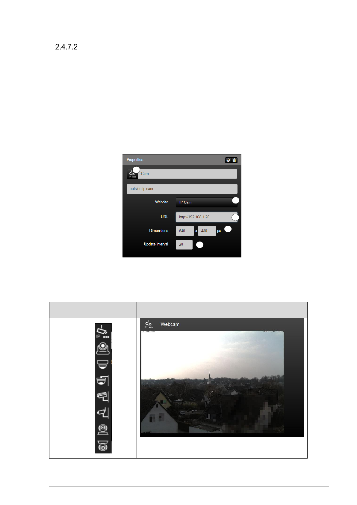
SV-SERVER-01 / SV-SERVER-INT 93 / 157
Website
/ IP
Selection of the icon library in
SV-Control
Operating and display element in SV-Home
IP
camera
1 2 3 4 5
IP camera
The "IP Camera" function (1) can be used to integrate an IP camera in the Smart Visu Server
into selectable areas. This means that it is possible within the user interface of your SVHome to, for example, display a live image of your entrance area from an IP camera. Local
IP cameras can not be displayed when using the remote access.
The web / IP address to be displayed can be entered in the "URL" input field (2). If there is
a username and password assigned to the camera it is possible to access the camera
directly by entering http://USERNAME:PASSWORD@url -webcam/ in the input field.
Using the two "Size" input fields (3), you can define the depiction size of the website within
SV-Home in pixels. You can define a reload time in seconds using the "Update interval"
input field (4).
Figure 62: Parameters of the "IP Camera" function
The "Website" function possesses the following individualisation options within the icon
library (5).
Table 46: Display of the "IP Camera" function
Page 95

SV-SERVER-01 / SV-SERVER-INT 94 / 157
INFORMATION
It´s recommended to integrate a maximum of 4 IP cameras at one
SV- server installation.
If a network camera is integrated with the "IP Camera" function, this results
in a permanent data flow in the home network, independent of the SV
Home call.
If a network camera is integrated with the function "Website", this only
requires a data flow in the home network when calling the assigned SV
Home area.
IP camera : tested Devices
Please note:
Some devices can’t be integrated via the function „IP-Camera“! Alternatively the camera can
be integrated by using the function „Website“. Furthermore, local IP cameras are not
displayable when using the remote access.
An IP camera can be integrated into the SV server in two different ways.
If the camera has an MJPEG stream, it can be inserted in the function "IP Camera". The
correct URL can be found on the websites of the manufacturers.
If there is no MJPEG stream available for the IP camera, the “Website / IP” function can call
the manufacturer's page with the stream.
Page 96
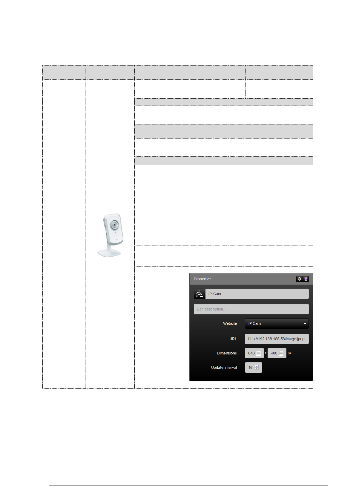
SV-SERVER-01 / SV-SERVER-INT 95 / 157
manufacturer
figure
title
function: IP-
Camera
function: Website
D-LINK
DCS930L
✔
✔
max. resolution
mode of transmission
640 x 480
network cable / WLAN
operating
voltage
IP-protection
5V / DC
-
configuration
IP-address:
receive from router
user name
(default):
admin
password
(default):
adminadmin
MJPEG
address
http://ip-address/image/jpeg.cgi
comment:
-
screenshot:
The following chart shows which device operates with which function:
(State May 2018)
Page 97
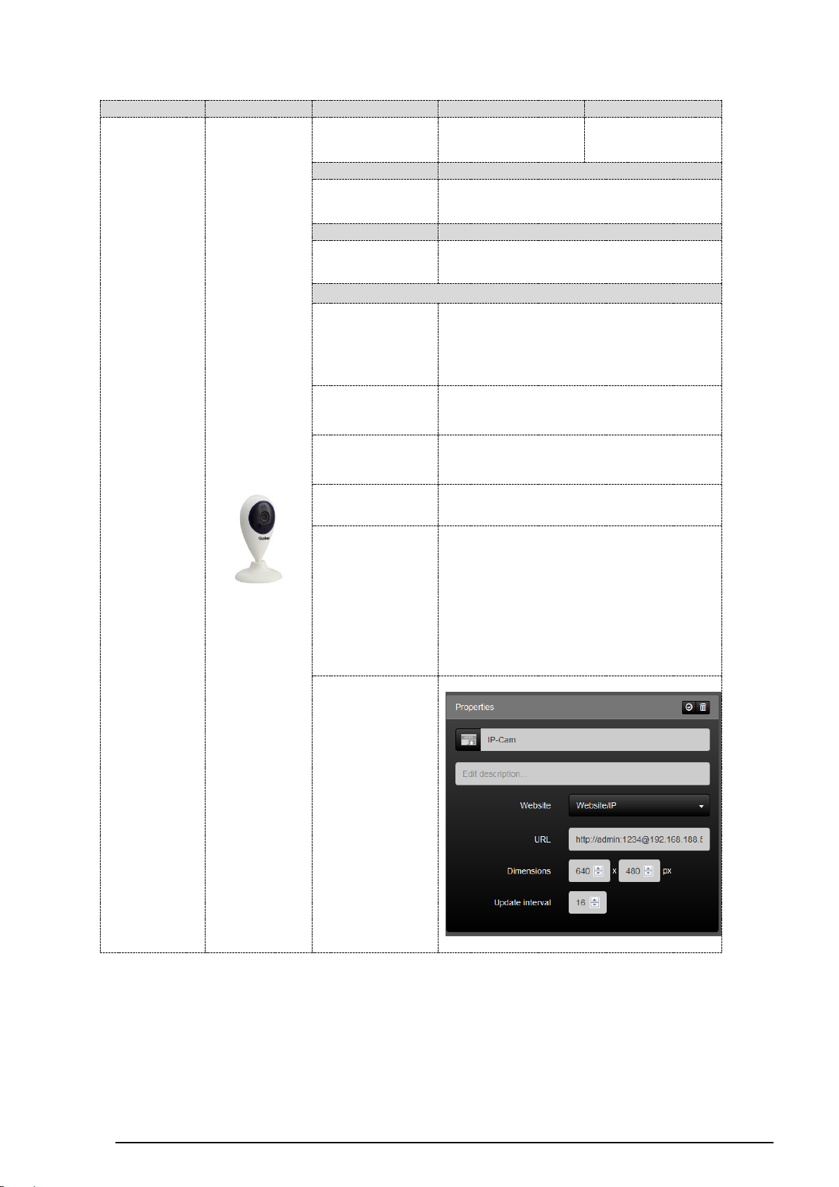
SV-SERVER-01 / SV-SERVER-INT 96 / 157
manufacturer
figure
title
function: IP-Camera
function: Website
Rollei
5040504
X
✔
max. resolution
mode of transmission
1280 x 720
WLAN
oerating voltage
IP-protection
5V / DC
-
configuration
IP-address:
receive from router
http://ip-addresse/
user name
(default):
-
password
(default):
-
MJPEG
address
-
comment:
Camera configuration via Rollei App
(Smart Phone e.g.)
Register and get user account (Rollei)
Connect to camera via user name and
password (at first do registration!)
Integrating camera to SV-Server via
function „Website“
screenshot:
Page 98
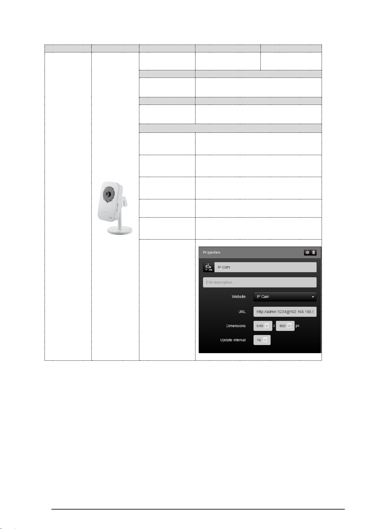
SV-SERVER-01 / SV-SERVER-INT 97 / 157
manufacturer
figure
title
function: IP-Camera
function: Website
EDIMAX
IC-3116W
✔
✔
max. resolution
mode of transmission
1280 x 720
network cable / WLAN
operating voltage
IP-protection
12 V / DC
configuration
IP-address: receive from router
user name
(default):
admin
password
(default):
1234
MJPEG
address
http://ip-address/snapshot.cgi
comment:
-
screenshot:
Page 99
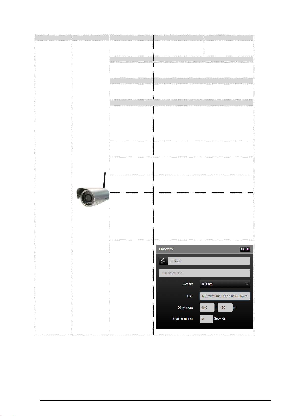
SV-SERVER-01 / SV-SERVER-INT 98 / 157
manufacturer
figure
title
function: IP-Camera
function: Website
Foscam
FI9804W
✔
✔
max. resolution
mode of transmission
1280 x 720
network cable / WLAN
operating voltage
IP-protection
12V / DC
IP 66
configuration
IP-address:
receive from router
IP-address + Port 88
(http://ip-address:88 e.g.)
user name
(default):
admin
password
(default):
(blank)
MJPEG
address
http://ip-addresse:88/cgi-
bin/CGIStream.cgi?cmd=GetMJStream
&usr=username&pwd=xxx
comment:
Calling camera respectively work
surface (Foscam) via IP-address and
function „Website“ (browser)
Install manufacturer PlugIn (browser
asks automatically)
Supports only 32-bit browsers
screenshot:
Page 100
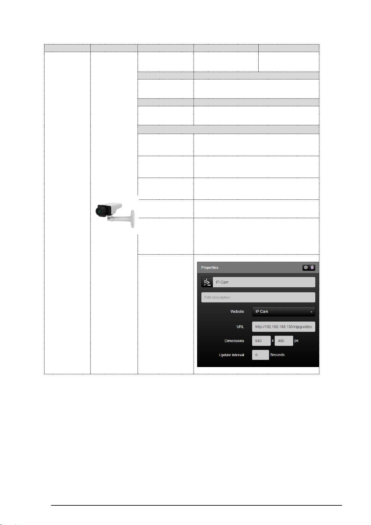
SV-SERVER-01 / SV-SERVER-INT 99 / 157
manufacturer
figure
title
function: IP-Camera
function: Website
Axis
M1124
✔
✔
max. resolution
mode of transmission
8 bis 28V DC /
PoE
network cable
operating voltage
IP-protection
12V / DC
-
configuration
IP-address: receive from router
user name
(default):
root
password
(default):
root
MJPEG
address
http://ip-
addresse/mjpg/video.mjpg?timestamp
comment:
Calling camera respectively work
surface (Axis) via IP-address and
function „Website“ (Browser)
screenshot:
 Loading...