

Page 1
Room controller display module 2-gang
Room controller display module 2-gang
Art. No. : RCD .. 4092M-01
Operating instructions
1 Safety instructions
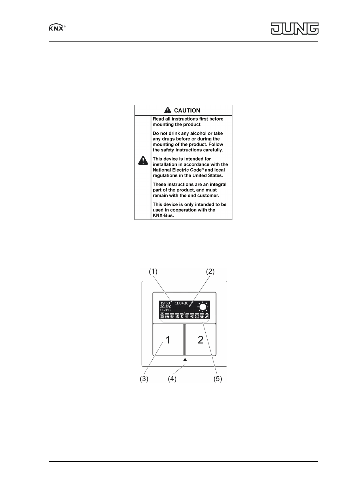
2 Device components
Figure 1
Figure 2
(1) Display
(2) Text area
(3) Buttons 1 and 2
(4) Operating and status LED
(5) Status icons
82574805
J0082574805
1/8
29.06.2017
Page 2

Room controller display module 2-gang
3 Function
System information
This device is a product of the KNX system and complies with the KNX directives. Detailed
technical knowledge obtained in KNX training courses is a prerequisite to proper understanding.
The function of this device depends upon the software. Detailed information on loadable soft
ware and attainable functionality as well as the software itself can be obtained from the
manufacturer´s product database. Planning, installation and commissioning of the device are
carried out with the aid of KNXcertified software. The latest versions of product database and
the technical descriptions are available on our website.
Intended use
Operation of loads, e.g. light on/off, dimming, blinds up/down, brightness values, tempera
tures, calling up and saving light scenes, etc.
Measurement and feedback control of the room temperature
Mounting only in the wall box listed under Mounting
4 Operation
Operating a function or load
Depending on the programming, a button can have up to three functions assigned to it –
upper/left, lower/right, entire surface. Operation depends on the specific function.
o Switching: Short press on button.
o Dimming: Long press on the button. The dimming process ends when the button is
released.
o Move Venetian blind: Long press on button.
o Stop or adjust Venetian blind: Short press on button.
o Call up light scene: Short press on button.
o Save light scene: Long press on button.
o Set value, e.g. brightness or temperature setpoint: Short press on button.
Operating modes and icons
The device compares the current room temperature with the setpoint temperature and controls
heating or cooling devices according to the current demand. The setpoint temperature depends
on the current operating mode and can be changed by the user, depending on the program
ming. The operating modes and the current controller status are shown in the display.
ó: Operating mode Comfort
ô: Operating mode Standby
õ: Operating mode Night
ö: Operating mode Frost/heat protection. At temperatures below 41 °F
(5 °C), the icon flashes.
÷: Dew point operation display; controller is disabled
óõ: Comfort extension Night
óö: Comfort extension Frost protection
Ü: Information mode is active. When the button is pressed, the display shows a text for the trig
gered function.
òñ...: Fan controller with fan level display. ë= Fan off.
ÝÞ...â: Heating mode with display of the heating stage
ãä...è: Cooling mode with display of the cooling
é: Energy requirement; currently there is heating or cooling.
þ: Operating display for switching channels 1...4 switched on: øùúû or ýüþ
Û: Buttons disabled
0: No setpoint shift
...– – 0 or 0 – –... : Setpoint temperature reduced or increased manually
82574805
J0082574805
2/8
29.06.2017
Page 3

Room controller display module 2-gang
o: Switch off buttonpress display, dim darker, move blind down, decrease value. Is activated
for approx. 3 seconds when pressed.
n: Switch on buttonpress display, dim brighter, move blind up, increase value. Is activated for
approx. 3 seconds when pressed.
Text display
The text area (2) in the display shows texts, e.g. music tracks, values, time, date, temperatures,
etc. A total of up to 12 lines on 4 pages are available. With appropriate programming, additional
icons in the text area can display more states, e.g. weather data, level information or scrolling
text with up to 2 x 14 characters.
Toggling between pages – depending on programming – can take place automatically by press
ing a button or can be controlled from other devices, e.g. a timer.
Second operating level
The second operating level contains functions for setting the room temperature control and
operating an alarm control center, if present, etc. The following settings are available. Some
items are not visible, depending on the programming.
Continuous controller
Comfort mode: setpoint temperature
Heating standby: temperature reduction
Cooling standby: temperature increase
Heating night reduction: temperature reduction
Cooling night reduction: temperature increase
Heat protection: setpoint temperature
Frost protection: setpoint temperature
Cooling mode max.: limit value
Cooling mode max.: difference
Alarm control center
The texts are sent from the alarm control center.
Information mode
Onetouch operation / doubletouch operation / Off
Presence
Switched on / switched off
Setpoint shift
Increase / reduction
Operating mode
Standby mode / Night mode / Frost/heat protection / Comfort mode
Fan levels
Off / Manual: Level 1 ... Level 8 / Automatic operation
Device information
RCS .. 4092 M .. / Firmware x V xx
Display
Contrast
Brightness
Pixel test
Save
Cancel
Operate second operating level
The second operating level is programmed and not disabled.
o Open: Simultaneously press the buttons 1 and 2 at the top (figure 1).
o Press button 1 at top or bottom.
The current setting is switched or the displayed value is increased or decreased.
o Press button 2 at top or bottom.
The display switches to the previous or next menu entry.
82574805
J0082574805
3/8
29.06.2017
Page 4
Room controller display module 2-gang
5 Information for electrically skilled persons
Figure 3
5.1 Mounting and electrical connection
Use special wall boxes
This device may only be installed into electrical wall boxes, flushmounted or Surface caps.
Art. no. Wall Box Dimensions
155604 For solid walls Dia. 2.3 in, depth 2.6 in
906401 For hollow walls Hole: dia. 2.67 in, Depth 2.4 in
i Wall boxes must be ordered separately.
o Wall boxes for solid walls have to be placed flush to the wall plaster.
o Hollow wall boxes were placed by circular cutter. A hole of dia. 2.67 in (68 mm) must be
made.
The wall box will be plugged into and screwed by integrated clamps.
Figure 4
82574805
J0082574805
4/8
29.06.2017
Page 5
Room controller display module 2-gang
Mounting and connecting the device
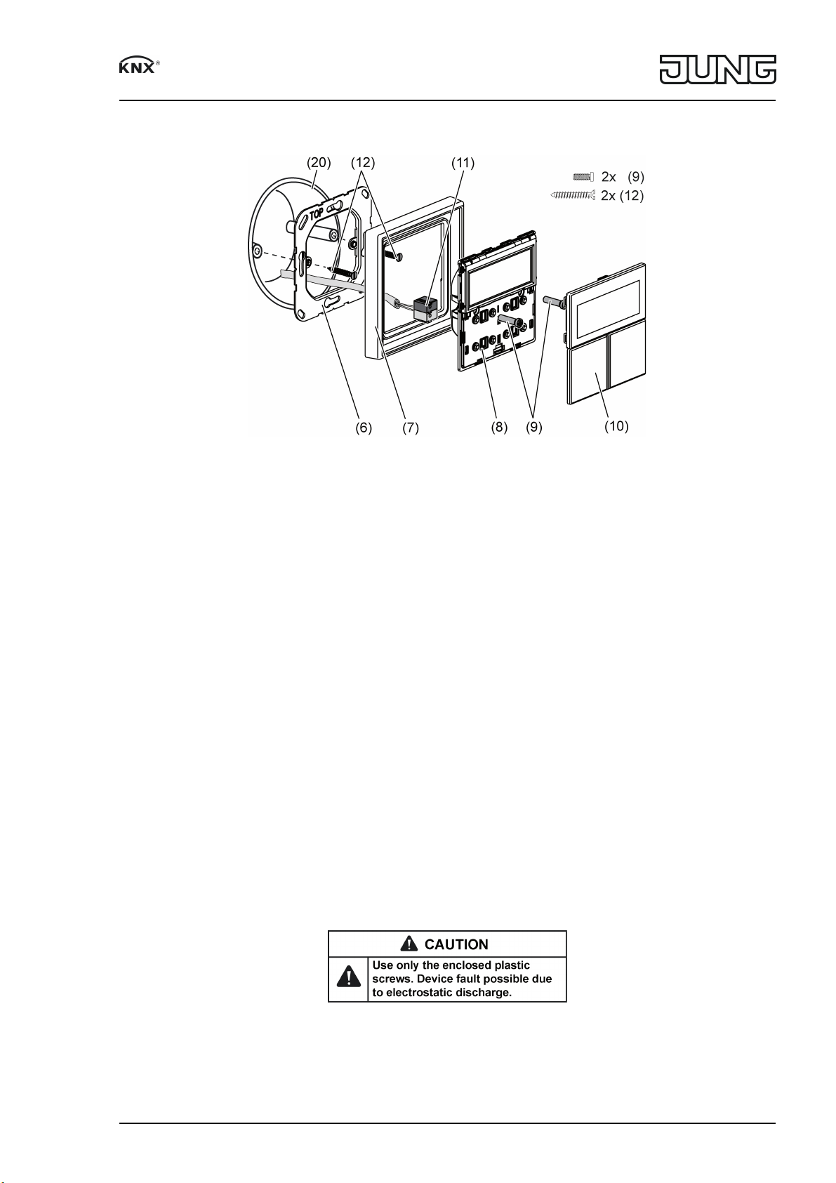
Figure 5: Mounting room controller
(6) Supporting frame
(7) Frame
(8) Room controller
(9) Fastening screws
(10) Buttons
(11) KNX device connection terminal
(12) Box screws
(20) Wall Box
Supporting frame side A for FD design. Supporting frame side B for LS programs.
Recommended installation height: 4.92 ft (1.50 m).
When the pushbutton extension module is used (figure 3): preferably mounted vertically. Use
large supporting frame (13). When mounting on only one wall box, fasten the lower screws into
the wall.
o Mount supporting frame (6) or (13) in the correct position onto a wall box. Note marking
TOP = above; marking A or B in front. Use only the enclosed box screws (12).
o Push frame (7) onto supporting frame.
o Pushbutton extension module: Insert connecting cable (16) in the correct position into slot
(15) in the device. Do not crimp the connecting cable (figure 3).
i Use only cables which are approved for KNX.
o Connect device (8) to the KNX using KNX connecting terminal (11) and push onto the sup
porting frame.
Figure 6
o Fix device (8) and pushbutton extension module (12) to supporting frame using the plastic
screws (9) enclosed. Tighten the plastic screws only lightly.
82574805
J0082574805
5/8
29.06.2017
Page 6

Room controller display module 2-gang
o Before mounting the buttons (10), load the physical address into the device. Loading the
physical address and application software.
Figure 7: Mounting with pushbutton extension module
(13) Supporting frame for mounting with pushbutton extension module
(14) Pushbutton extension module
(15) Slot for pushbutton extension module
(16) Pushbutton extension module connecting cable
5.2 Commissioning
Loading the physical address and application software
Project design and commissioning with ETS3.0d with Patch A or more recent.
The device is connected and ready for operation.
The pushbuttons are not mounted yet.
i If the device does not receive any application software, or the wrong application software,
then the blue operation LED flashes slowly.
82574805
J0082574805
Figure 8: Activating programming mode
6/8
29.06.2017
Page 7

Room controller display module 2-gang
o Activate programming mode: Press and hold pushbutton (17). Then press pushbutton
(18).
The operation LED (19) flashes quickly.
o Load the physical address into the device.
The operation LED (19) returns to its previous state – off, on, or flashing slowly.
o Write the physical address on the device label.
o Load application software into the device.
Mounting the control surfaces
The control surfaces are available as a complete set of buttons. Individual buttons can be
replaced using buttons with icons.
i The mounting spider is not required to mount the buttons.
The physical address is loaded into the device.
o Place control surfaces on the device in the right orientation and snap in with a short push.
6 Appendix
Disposal
Please consider your local regulation for disposal and electronic waste recycling.
6.1 Technical data
KNX medium TP
Commissioning mode S-mode
Rated voltage KNX DC 21 ... 30V SELV
Current consumption KNX max. 20mA
Connection mode KNX device connection terminal
Ambient temperature 23 ... 113°F
(-5 ... +45 °C)
Storage/transport temperature -13 ... +158°F
(-25 ... +70 °C)
Protection class III
Purpose of control Operating Control
Construction of control Independently Mounted Control for Flush
Mounting
Pollution Degree PD 2
Impulse Voltage 330V
6.2 Accessories
Cover kit 1-gang Order No. ..401TSA..
Cover kit 2-gang Order No. ..402TSA..
Cover kit 3-gang Order No. ..403TSA..
Cover kit 4-gang Order No. ..404TSA..
Push-button extension module, 1-gang Order No. 4091TSEM01
Push-button extension module, 2-gang Order No. 4092TSEM01
Push-button extension module, 3-gang Order No. 4093TSEM01
Push-button extension module, 4-gang Order No. 4094TSEM01
6.3 Warranty
If you have any questions about this product, contact:
Jung USA, Inc.
350 Fifth Avenue, Suite 5220
New York, NY 10118
Phone: +1 800.311.6135
Email: sales@jungcontrols.com
www.jungcontrols.com
For the product warranty, please refer to the attached document.
All rights reserved
82574805
J0082574805
7/8
29.06.2017
Page 8

Room controller display module 2-gang
©
ALBRECHT JUNG GMBH & CO. KG
Volmestraße 1
58579 Schalksmühle
GERMANY
82574805
J0082574805
8/8
29.06.2017
 Loading...