

Jun-Air 87R-4P Operation & Maintenance Manual
Part No. 6190900 (Rev B)
® Registered Trademark/™ Trademark of JUN-AIR Inc. ©Copyright 2017 JUN-AIR Manufacturing Inc. All Rights Reserved.
WWW.JUN-AIR.COM
ISO 9001 CERTIFIED
87R-4P Compressed
Air System
Operation & Maintenance Manual

6190900 (Rev B) 87R-4P Compressor System User Guide
WARNING
PLEASE READ THIS MANUAL COMPLETELY BEFORE INSTALLING AND USING
THIS PRODUCT. SAVE THIS MANUAL FOR FUTURE REFERENCE AND
KEEP IN THE VICINITY OF THE PRODUCT.
Dear Customer:
Congratulations on the purchase of your new JUN-AIR Industrial Compressed Air System.
This system’s intended purpose is for industrial and laboratory compression applications. It is to be used in
accordance with UL1450/CSA 22.2 standards, along with all applicable codes. The system utilizes an oil-less
rocking piston compressor that produces clean, dry, oil-free pressurized air flow when connected to an industrial or laboratory device. The tank ensures that a constant supply of air is available to the device.
A pressure regulator and safety relief valve are also included to ensure safe operation of the system. This
manual provides installation, operation and preventative maintenance guidelines that should be followed to
ensure correct/reliable performance of this system.
Please carry out all maintenance according to relevant instructions.
Section Page Number
Declaration of Conformity 3
Table of Symbols 4
System Features 5
Installation and Operation 7
Maintenance 11
Troubleshooting 21
Warranty Policy 22
2
We reserve the right to make any alterations which may be due to any technical improvements
© 2017, JUN-AIR
Printed in the USA
87R-4P Compressor System User Guide 6190900 (Rev B)
Declaration of Conformity
Konformitätsbescheinigung
Certificat de Conformité
Declaración de Conformidad
Conformiteitsverklaring
Overensstemmelseserklæring
GB The manufacturer Gast Manufacturing, Inc. declares that the compressor is in conformity with:
• 2014/68/EU Pressure Equipment Directive
• 2014/29/EU Council Directive relating to Simple Pressure Vessels
• 2006/42/EC Machinery Directive
• 2014/30/EU EMC Directive
• 2006/95/EC Low Voltage Directive
• 2011/65/EU RoHS 2 Directive
• 2012/19/EU WEEE Directive
• 1907/2006 and 340/2008 REACH Regulation
DE Der Hersteller Gast Manufacturing, Inc. bescheinigt, dass der Kompressor entspricht:
• 2014/68/EU Druckgeräterichlinie
• 2014/29/EU Richtlinie der einfachen Druckbehälter
• 2006/42/EC Richtlinie zur Sicherheit von Maschinen
• 2014/30/EU Richtlinie der Elektromagnetischen Verträglichkeit
• 2006/95/EC Richtlinie für Niederspannung
• 2011/65/EU RoHS Directive
• 2012/19/EU WEEE Directive
• 1907/2006 und 340/2008 REACH Regulativ
FR Le fabricant Gast Manufacturing, Inc. déclare que le compresseur est conforme aux directives suivantes:
• 2014/68/EU Directive équipements sous pression
• 2014/29/EU Directive relative aux appareils à pression simple
• 2006/42/EC Directive sur la sécurité des machines
• 2014/30/EU Directive sur la compatibilité électro-magnétique
• 2006/95/EC Directive sur les basses-tensions
• 2011/65/EU Directive RoHS
• 2012/19/EU Directive DEEE
• 1907/2006 et 340/2008 Réglementation REACH
ES El fabricante Gast Manufacturing, Inc. declara que el compresor está conforme con:
• 2014/68/EU Directiva de equipos a presión
• 2014/29/EU Directiva en relación a recipientes a presión simple
• 2006/42/EC Directiva de Seguridad de maquinaria
• 2014/30/EU Directiva de Compatibilidad eléctrica magnética
• 2006/95/EC Directiva de baja tensión
• 2011/65/EU Directiva de RoHS
• 2012/19/EU Directiva de WEEE
• 1907/2006 y 340/2008 Reglamento REACH
NL De fabrikant Gast Manufacturing, Inc. verklaart dat de compressor in overeenstemming is met:
• 2014/68/EU Richtlijn Drukapparatuur
• 2014/29/EU Richtlijn voor eenvoudige drukvaten
• 2006/42/EC Machinerichtlijn
• 2014/30/EU Richtlijn inzake Electromagnetische Compatibilitet
• 2006/95/EC Laagspanningsrichtlijn
• 2011/65/EU RoHS Richtlijn
• 2012/19/EU WEEE Richtlijn
• 1907/2006 en 340/2008 REACH Verordening
DK Producenten Gast Manufacturing, Inc. bekræfter hermed at kompressoren er i overensstemmelse med:
• 2014/68/EU Direktivet om trykbærenole udstyr
• 2014/29/EU Direktivet vedrørende simple trykbeholdere
• 2006/42/EC Maskindirektivet
• 2014/30/EU EMC-direktivet
• 2006/95/EC Lavspændingsdirektivet
• 2011/65/EU RoHS Direktivet
• 2012/19/EU WEEE Direktivet
• 1907/2006 og 340/2008 REACH Forordningen
© 2017, JUN-AIR
We reserve the right to make any alterations which may be due to any technical improvements
Printed in the USA
3
6190900 (Rev B) 87R-4P Compressor System User Guide
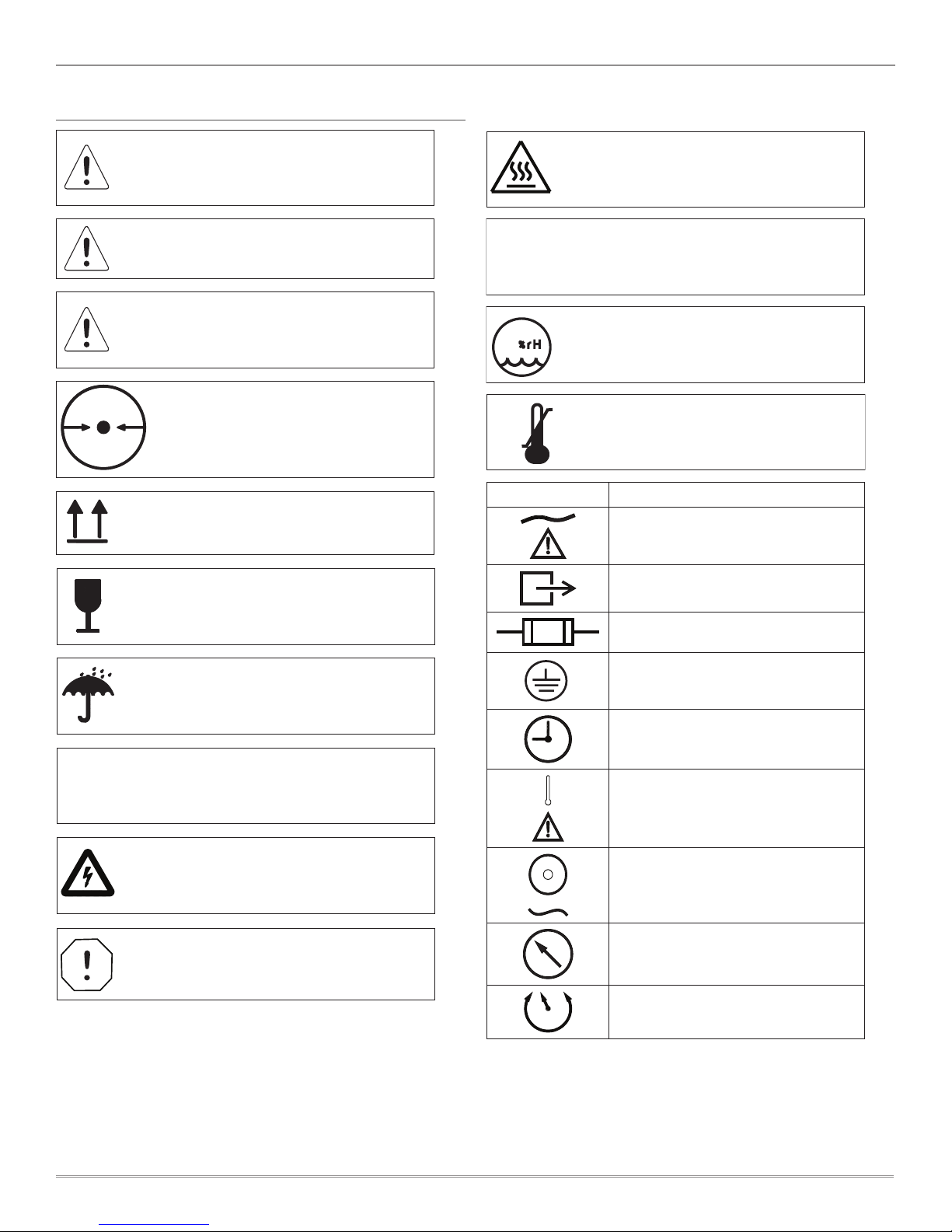
TABLE OF SYMBOLS
DANGER: Indicates an imminently hazardous
situation which will result in serious or fatal
injury if not avoided. This symbol is used only
in the most extreme conditions.
WARNING: Indicates a potentially hazardous
situation which could result in serious injury
if not avoided.
CAUTION: Indicates a potentially hazardous
situation which may result in minor or
moderate injury if not avoided. It may also be
used to alert against unsafe practices.
Indicates the acceptable lowest barometric
372MM HG
.49 ATM
pressure conditions in which this unit
can be shipped.
Indicates package should be handled with
these symbols pointing up.
FRAGILE: Handle package with care.
WARNING: To Avoid Serious Burns.
Do not touch surface during operation.
ON
I
OFF
O
95
-28 °C
-18 °F
Indicates the ON and OFF position
for the equipment power switch.
Indicates the acceptable maximum
relative humidity for shipping.
+65 °C
+149 °F
Indicates the acceptable shipping
temperature range.
Symbol Description
A/C power
Air outlet port
Indicates this package must be kept dry.
INDUSTRIAL ELECTRICAL EQUIPMENT
With respect to electrical shock, fire, mechanical,
and other specified hazards only in accordance
with UL1450.
Electrical Shock Hazard.
Risk of electric shock present. Make sure power
is disconnected before attempting this procedure.
Equipment Alert: Indicates a potentially
hazardous situation that could result in
equipment damage if not avoided.
Fuse location
Ground
Hour meter
Over-temp indicator light
Power on indicator light
Pressure gauge
Pressure regulator valve
4
We reserve the right to make any alterations which may be due to any technical improvements
© 2017, JUN-AIR
Printed in the USA
87R-4P Compressor System User Guide 6190900 (Rev B)
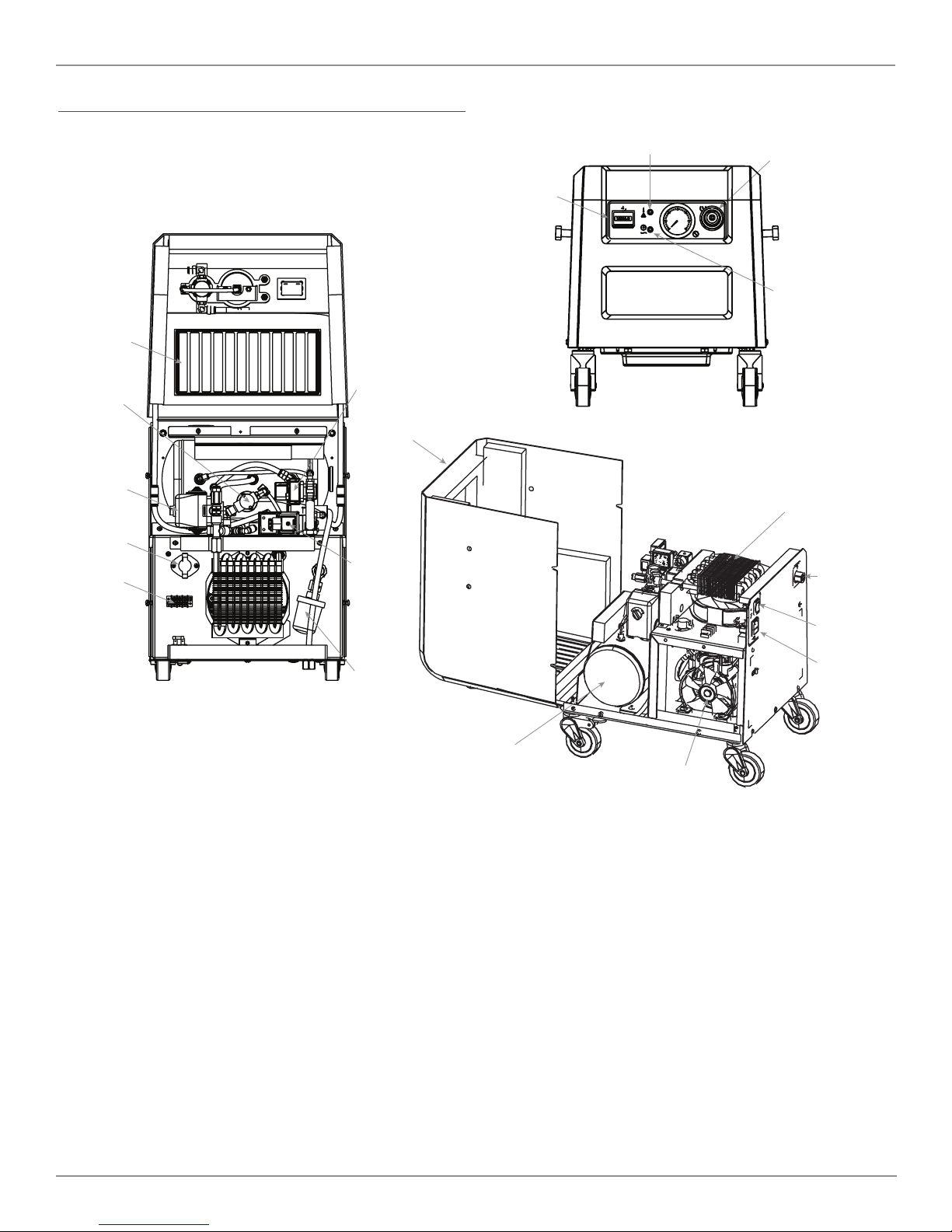
Cover
Tank
Compressor
IEC plug
& fuse
Power supply
switch
Air
outlet
Output
pressure
regulator
Power
indicator
light
Over-temp
indicator
Hour
meter
Pressure
switch
5 µm
autodrain
filter
System
intake
filter
Drain
solenoid
Dump
solenoid
Compressor
intake
filter
Thermostat
Terminal
block
Heat
exchange
SYSTEM FEATURES
© 2017, JUN-AIR
We reserve the right to make any alterations which may be due to any technical improvements
Printed in the USA
5
6190900 (Rev B) 87R-4P Compressor System User Guide
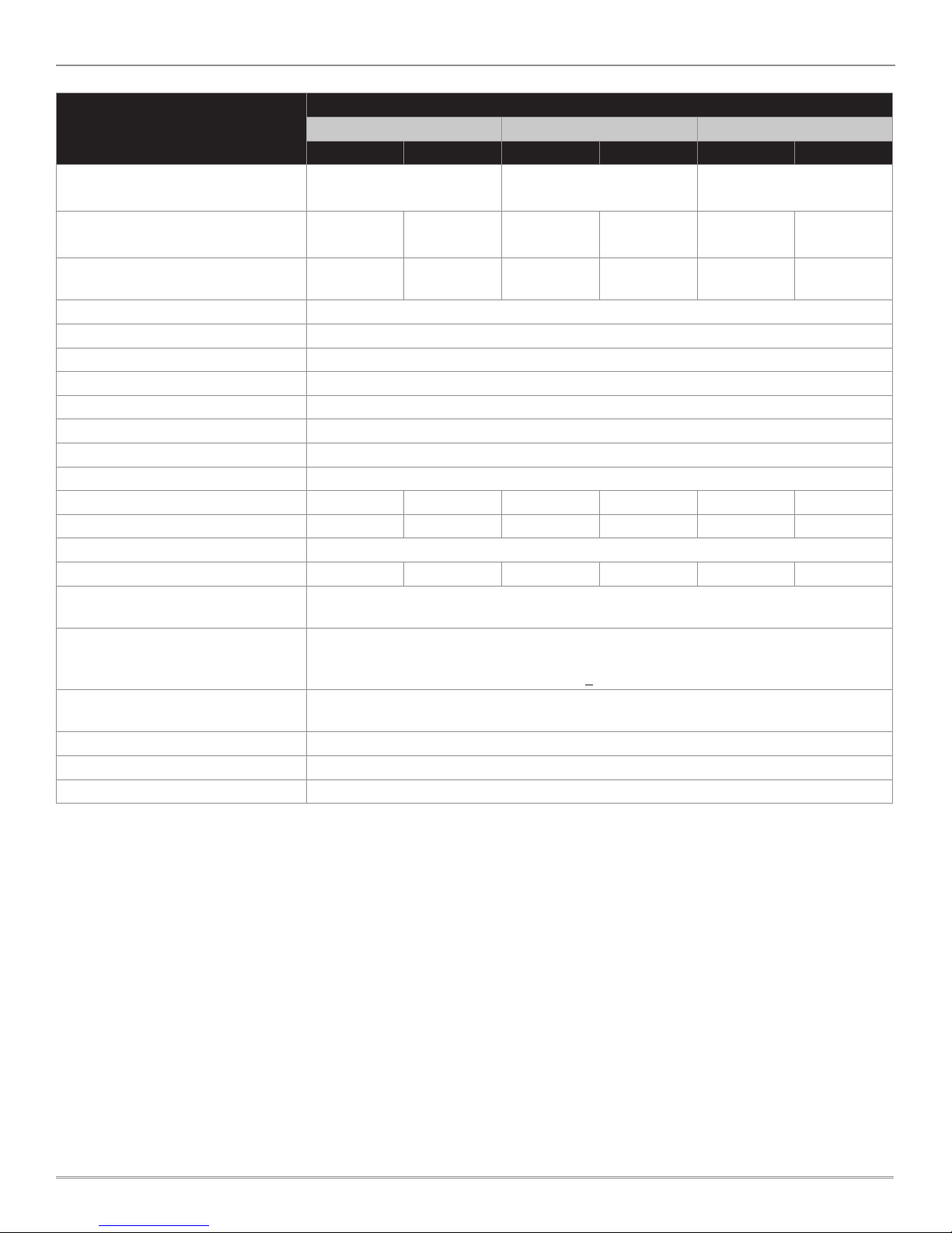
NO DRYER
Specifications
50Hz 60Hz 50Hz 60Hz 50Hz 60Hz
Model Numbers
100V 115V 230V
1770018 1770008
1770009 (NA)
1770010 (EU/UK)
Continuous System
Output Flow @ 4 bar (58 psi)
Continuous System
Output Flow @ 8 bar (116 psi)
Cut-in Pressure
Cut-out Pressure
1
1
46 SLPM
[1.6 SCFM]
27 SLPM
[1.0 SCFM]
51 SLPM
[1.8 SCFM]
31 SLPM
[1.1 SCFM]
46 SLPM
[1.6 SCFM]
27 SLPM
[1.0 SCFM]
6 bar [87 psi]
8 bar [116 psi]
51 SLPM
[1.8 SCFM]
31 SLPM
[1.1 SCFM]
46 SLPM
[1.6 SCFM]
27 SLPM
[1.0 SCFM]
51 SLPM
[1.8 SCFM]
31 SLPM
[1.1 SCFM]
Maximum Operational Pressure 8 bar [116 psi]
Dew Point Suppression
2
N/A
Air Filtration 5 µm
Safety Relief Valve Pressure 9.3 bar (135 psi)
High Temperature Indication ≥ 60 °C [140 °F] in compressor chamber
Air Connections 1/4 in BSPP
Current, A 5.0 5.8 4.8 5.3 2.6 2.9
Power Consumption, W 450 550 500 600 550 650
Fuse Specifications 12.5 A, 250 Vac, time delay
Sound Level, dB(A) 46 48 46 48 46 48
Operating Ambient Conditions
10 °C to 40 °C [50 °F to 104 °F]
10 - 95% RH*
-28 °C to 65 °C [-18 °F to 149 °F]
Storage Ambient Conditions
10 - 95% RH*
Barometric pressure >372 mm-Hg [14.7 in-Hg]
System Dimensions
W x H x D
406 mm x 495 mm x 439 mm
[16 in W x 19.5 in D x 17.3 in H]
System Weight 29.5 kg [65 lb]
Shipping Weight 35.0 kg [77 lb]
Regulatory Certifications UL 1450 / CSA 22.2 / CE
1
The compressor switches on and off at the cut-in and cut-out pressures, respectively. The cut-in and cut-out pressures are adjustable.
2
Membrane dryer specifications are available upon request.
* Avoid conditions that promote condensation on the equipment.
6
We reserve the right to make any alterations which may be due to any technical improvements
© 2017, JUN-AIR
Printed in the USA
87R-4P Compressor System User Guide 6190900 (Rev B)
INSTALLATION AND OPERATION
Intended Use
To provide compressed air for use with industrial or laboratory devices as a primary or back-up air source.
JUN-AIR compressor systems meet or exceed the most
current and highest safety standards, which are:
• UL1450, 4th edition
• CSA C22.2 68
• ISO 9001:2008
• Ingress protection: IP50
• 2006 / 42 / EC Directive
• RoHS compliant
To ensure the safety potential of this equipment is
achieved, please:
Make sure your equipment is installed according to the
instructions provided in this manual and make sure the
installation checklist is completed prior to starting the
equipment.
DANGER
The equipment is not suitable for use in the presence
of a flammable anesthetic mixture or with oxygen or
nitrous oxide. DO NOT OPERATE THE EQUIPMENT IF
THESE CONDITIONS EXIST.
Unpacking
1. Cut the banding strap from the carton and remove the
lid and cardboard inserts.
2. Visually inspect the entire system for shipping damage
and verify that the following accessories have been
included: two (2) locking casters, two (2) non-locking
casters, four (4) vibration-isolation feet, four (4) studs,
four (4) washers, and one (1) power cable.
a. If the contents were damaged during shipping,
contact the freight carrier to file a claim.
b. If parts are missing, contact the supplier.
3. Use caution when removing the system from the
remaining packaging. Retain the packaging material for
future use, if necessary.
4. Install the casters or rubber mounting feet.
Before You Install...
Equipment Alert: Compressors are oil-less and
require NO lubrication.
Equipment Alert: The system must be installed in a
temperature-controlled and/or ventilated room to
ensure operational ambient temperature of 50 °F to
104 °F [10 °C to 40 °C]. A 12-inch clearance is required
on each side and top of unit to allow air flow.
Failure to do so could cause premature loss of
system performance and void warranty.
Transportation and Storage Conditions
• Temperature: -28 °C (-18 °F) to 65 °C (149 °F)
• Relative humidity: 10% to 95%
• Minimum barometric pressure: 372 mm•Hg
(14.7 in•Hg)
• Keep the system dry at all times.
• Do not stack units during shipment, installation, or usage.
Equipment Alert: Refer servicing to an authorized
service representative.
© 2017, JUN-AIR
We reserve the right to make any alterations which may be due to any technical improvements
Printed in the USA
Personal Safety
DANGER
Risk of fire or explosion when using flammable substances.
Do not operate the system in an area containing combustible
gases or anesthetic mixtures.
CAUTION
Never leave children unattended near the system when in use.
WARNING
Property damage and/or personal injury may result
if directions are not followed or if the manufacturer’s
replacement parts/accessories are not used.
WARNING
Only connect equipment suitable for the listed maximum
pressure of the system.
7
 Loading...