

Compressor
JUN-AIR® is a registered trademark of Gast Manufacturing, Inc. and Gast Group Ltd. ©Copyright 2015 Gast Manufacturing, Inc. All rights reserved.
WWW.JUN-AIR.COM
ISO 9001 CERTIFIED
Model 86/87R System
86R-4B, 87R-4B, 87R-15B, 87R-25B
6190755

6190755 (Rev A) 86/87R Compressor System User Guide
Table Of Contents
Section Page Number
Declaration of Conformity 3
Operating Manual 4
Diagrams / Schematics 8
Exploded Views 11
Parts and Accessories 19
Technical Data & Specifications 21
Pictures & Illustrations 26
2
We reserve the right to make any alterations which may be due to any technical improvements
© 2015, JUN-AIR
Printed in the USA
86/87R Compressor System User Guide 6190755 (Rev A)
Declaration of Conformity
Konformitätsbescheinigung
Certi cat de Conformité
Declaración de Conformidad
Conformiteitsverklaring
Overensstemmelseserklæring
GB e manufacturer Gast Manufacturing, Inc. declares that the compressor is in conformity with:
• 2009/105/EC Council Directive relating to Simple Pressure Vessels
• 2006/42/EC Machinery Directive
• 2004/108/EC EMC Directive
• 2006/95/EC Low Voltage Directive
• 2011/65/EU RoHS 2 Directive
• 2012/19/EU WEEE Directive
• 1907/2006 and 340/2008 REACH Regulation
DE Der Hersteller Gast Manufacturing, Inc. bescheinigt, dass der Kompressor entspricht:
• 2009/105/EC Richtlinie der einfachen Druckbehälter
• 2006/42/EC Richtlinie zur Sicherheit von Maschinen
• 2004/108/EC Richtlinie der Elektromagnetischen Verträglichkeit
• 2006/95/EC Richtlinie für Niederspannung
• 2011/65/EU RoHS Directive
• 2012/19/EU WEEE Directive
• 1907/2006 and 340/2008 REACH Regulativ
FR Le fabricant Gast Manufacturing, Inc. déclare que le compresseur est conforme aux directives suivantes:
• 2009/105/EC Directive relative aux appareils à pression simple
• 2006/42/EC Directive sur la sécurité des machines
• 2004/108/EC Directive sur la compatibilité électro-magnétique
• 2006/95/EC Directive sur les basses-tensions
• 2011/65/EU Directive RoHS
• 2012/19/EU Directive DEEE
• 1907/2006 et 340/2008 Réglementation REACH
ES El fabricante Gast Manufacturing, Inc. declara que el compresor está conforme con:
• 2009/105/EC Directiva en relación a recipientes a presión simple
• 2006/42/EC Directiva de Seguridad de maquinaria
• 2004/108/EC Directiva de Compatibilidad eléctrica magnética
• 2006/95/EC Directiva de baja tensión
• 2011/65/EU Directiva de RoHS
• 2012/19/EU Directiva de WEEE
• 1907/2006 and 340/2008 Reglamento REACH
NL De fabrikant Gast Manufacturing, Inc. verklaart dat de compressor in overeenstemming is met:
• 2009/105/EC Richtlijn voor eenvoudige drukvaten
• 2006/42/EC Machinerichtlijn
• 2004/108/EC Richtlijn inzake Electromagnetische Compatibilitet
• 2006/95/EC Laagspanningsrichtlijn
• 2011/65/EU RoHS Richtlijn
• 2012/19/EU WEEE Richtlijn
• 1907/2006 and 340/2008 REACH Verordening
DK Producenten Gast Manufacturing, Inc. bekræ er hermed at kompressoren er i overensstemmelse med:
• 2009/105/EC Direktivet vedrørende simple trykbeholdere
• 2006/42/EC Maskindirektivet
• 2004/108/EC EMC-direktivet
• 2006/95/EC Lavspændingsdirektivet
• 2011/65/EU RoHS Direktivet
• 2012/19/EU WEEE Direktivet
• 1907/2006 and 340/2008 REACH Forordningen
© 2015, JUN-AIR
We reserve the right to make any alterations which may be due to any technical improvements
Printed in the USA
3
6190755 (Rev A) 86/87R Compressor System User Guide
Operating manual
Information
Please note that you can find the pictures and figures we
are referring to in the back of the manual
Important - read this first!
Please read the following information and operating instructions included with this product
before use. This information is for your safety and it is important that you follow these
instructions. It will also help prevent damage to the product. Failure to operate the unit in
accordance with the instructions or using JUN-AIR unauthorized spare parts can cause
damage to the unit and could cause serious injury.
CAUTION: To reduce risk of electric shock
• Only authorized service agents should carry out service. Removing parts or
attempting repairs can create an electric shock. Refer all servicing to qualified service
agents.
• If this unit is supplied with a three-pin plug, connect with a properly earthed outlet
only.
WARNING: To reduce risk of electrocution
• Do not use this unit with electrical voltages other than stated on the rating plate.
• Never leave this product unattended when plugged in.
• Always unplug this unit immediately after use.
• Store in a dry place.
• Do not use this product in or near liquid or where it can fall or be pulled into water or
other liquids.
• Do not reach for this product if it has fallen into liquid. Unplug immediately.
• This unit is not weatherproof. Never operate outdoors in the rain or in a wet area.
DANGER: To reduce risk of explosion or fire
• During spraying with combustible liquids risk of explosion may arise, particularly in
closed rooms
• Do not use this product in or near explosive atmospheres or where aerosol products
are being used.
• Do not pump any other gases other than atmospheric air.
• Do not pump combustible liquids or vapours with this product; do not use it in or
near areas with combustible or explosive liquids or vapours.
• Do not use this unit near naked flames.
CAUTION: To prevent injury
• Compressed air can be dangerous; do not direct airflow at a persons head or body.
• Always keep the system out of reach of children.
• Never operate this product if it has a damaged power lead or plug, if it has been
dropped or damaged, or if it has fallen into water. Return the product to a service
centre for examination and repair.
• Keep the electrical cable away from hot surfaces.
• Ensure all openings are kept free of restriction and never place the system on a soft
surface where the openings may be blocked. Keep all openings free from dust, dirt
and other particles.
• Never insert fingers or any other objects into fans.
• This unit is thermally protected and can automatically restart when the overload
resets.
• Wear safety glasses, when servicing this product.
• Use only in well ventilated areas.
• This product may only be connected to units or tools with a max. pressure higher or
equal to that of the system.
• The surface of the system can get hot. Do not touch system system during
operation.
Failure to observe the above safety precautions could result in severe bodily injury,
including death in extreme cases.
IMPORTANT: General directions for use
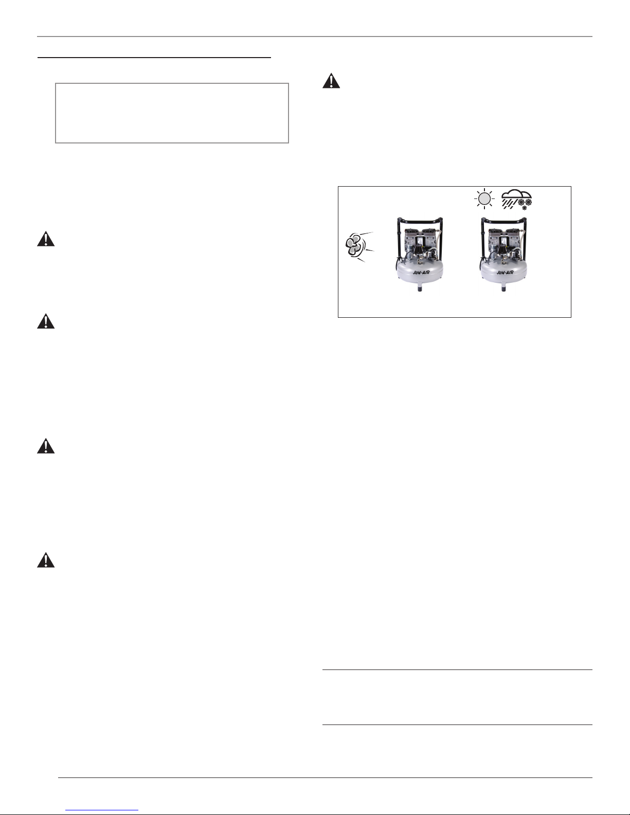
• Protect the system against rain, moisture, frost and dust.
• The system is constructed and approved for a max. pressure as stated under
Technical Specifications.
• Do not operate system at ambient temperatures exceeding 40°C/104°F or falling
below 5°C/41°F.
• If the supply lead on the system is defective, an authorized JUN-AIR distributor or
other qualified personnel must carry out the repair.
GOOD BAD
Min. 5°C/41°F • Max. 40°C/104°F
Warranty
Provided that the operational instructions, maintenance, and service have been carried
out, your JUN-AIR system is guaranteed against faulty material or workmanship for 2
years.
The air receiver is guaranteed for 5 years.
The guarantee does not cover damage caused by violence, misuse, incorrect repairs or
use of unoriginal spare parts.
Costs of transportation of parts/equipment are not covered by the guarantee.
JUN-AIR’s Conditions for Sale and Delivery will generally apply.
Gast Manufacturing, Inc. A/S reserves the right to change technical specifications/
constructions.
Contents of box
Your system should be delivered in a clean and undamaged box. If not, contact
your distributor immediately. The box should contain the following:
• 1 86/87R-XB system
• 1 system operating manual & 1 filter/regulator manual
• Individually packaged or attached filter/regulator
• 100 cm x 6 mm tube for filter/regulator autodrain line
Installation
Your JUN-AIR system is very easy to operate. Observe the following simple
instructions and you will get many years’ service from your unit.
• Visually inspect unit for shipping damage, contact your supplier
immediately if you think the unit may have been damaged.
Warning!
To avoid the risk of electric shock, do not install the system in
areas where it may get in contact with water or other liquids. In
which case protection is required.
0
• Use only pressure pipes tolerating a constant temperature of min. 150
Ensure that the pressure pipes have a sufficient internal diameter to avoid
pressure loss in the system. Check for leaks.
C.
4
We reserve the right to make any alterations which may be due to any technical improvements
© 2015, JUN-AIR
Printed in the USA

86/87R Compressor System User Guide 6190755 (Rev A)
• Install product on a rigid level surface maintaining a minimum of 6 in/15
cm clearance all around the unit and a 12 in/30 cm clearance above the
system.
• Sufficient cooling from the surroundings is important. Place the system
in a dustfree, dry and cool, yet frostfree, room. Do not install in a closed
cupboard, unless adequate openings for ventilation are available on top
and bottom (minimum 500 cm²/77.5 in² each). If the system is placed
under a table, a minimum of 12 cm/5 in free height must be available
above the system or an opening of Ø30cm/11.8 inches, corresponding
to the top of the system, may be cut in the table. Ensure that the system
stands firmly on the floor.
• The intake air may be supplied from another place (for instance outside).
Ensure that hoses for the intake are sufficient to avoid performance loss
and that any alternate filter used has the same micron rating (50μm) as the
JUN-AIR intake filter.
Electrical installation
Warning!
Incorrect electrical connection may result in electric shock. The
electrical connection must be carried out in accordance with
local electrical regulations and by qualified electrical engineers.
Note!
Earthing of all AC models must be ensured during installation. The capacitor
must be earthed, as failure to do so may cause electric shock when touched.
Plug the system into an earthed socket of nominal voltage and ensure that
fusing is adequate.
Adjustment of pressure switch
Warning!
If maximum pressure is exceeded, reduced lifetime may result.
Contact JUN-AIR for information on operation at higher
pressure.
• All systems may run at 100% continuous operation, but 50% operation is
recommendable to prolong lifetime.
• The system should be sized so that the tank is capable of supplying air
100% of the time and the compressors only run at 50%.
• Do not lubricate the oil-less system with oil, as this will destroy important
components.
• Start the system using the 0/1 switch on the pressure switch. The system
will automatically switch off at the preset pressure. If the system does not
start it may be due to pressure in the receiver, and the system will then
start automatically when the pressure reduces to approx. 6 bar/87 psi.
• Adjustment of pressure (see back of manual)
A: Max. pressure adjustment (cut-out)
B: Differential adjustment (cut-in)
The cut-in pressure (normally 6 bar) is set by adjustment of differential
screw B. Turn clockwise to reduce cut-in pressure. The cut-out pressure is
set by even adjustment of the two screws A. (Cut-in pressure + differential
= cut-out pressure). Turn clockwise to increase cut-out pressure. The
switch is normally factory set for operation at 6-8 bar (approx. 90-120 psi).
Fault finding and repair
AC models
• For electrical connection, refer to schematic in back of this manual.
• Check system serial number label for frequency and voltage to ensure
that it corresponds to the voltage and frequency used for the system. The
voltage stated on the system plate: 120/240V (/) means that the system
can operate at 120V or 240V, but this requires recoupling of the internal
wiring from the electrical system (see the electrical diagrams). 220-230V
(-) means that the system may operate within the range of 220V to 230V
without recoupling of the internal wiring.
• Capicitor is wired to motor via terminal box on side of motor.
• Accessorries are wired through the system pressure switch.
Operation
• If the temperature of the system is extremely low (for instance after
transportation or stocking), allow system to get to room temperature before
switching on the system.
• Do not use system for compression of liquids and dangerous gasses,
such as petrol vapour and solvents.
Important
This system is only suitable for atmospheric air.
• Do not remove protection covers during operation as it may cause electric
shock or risk of other personal injury (ie: terminal box, pressure switch).
• Ensure that system is correct for air supply flow required, see Technical
Specifications.
• Open the outlet cock on the receiver and connect equipment.
Important!
Switch off and isolate from electrical supply before removing
any parts from the system. Empt y air receiver of air before
dismantling parts of system unit’s pressure system.
1. System does not start:
a) No power from mains. Check fuses and plug.
b) Breakage or loose joints in electrical connections.
c) Defective capacitor.
d) The thermal protection has switched off the pump due to overheating.
When cooled the pump will automatically turn on at a suitable
operation temperature. Go through the points in step 5.
e) The system has not been unloaded and there is back pressure. Make
sure that the system is unloaded each time it stops.
f) The pump is locked.
g) Pressure in the air receiver is too high for activation of the pressure
switch. The pressure switch makes circuit only when pressure has
dropped to preset start pressure. Empty receiver.
2. System does not start, makes a buzzing sound followed by a
clicking noise (cannot start against high pressure):
a) Leaky non-return valve. Remove the flexible pressure pipe and clean
to find out whether air leaks from the valve. If so, clean or replace.
3 System works, but pressure does not increase:
a) Intake filter clogged. Replace.
b) Leaks in fittings, tubes or pneumatic equipment. Check with soapy water
or by letting unit stay overnight with disconnected mains. Pressure drop is
not to exceed 1 bar.
c) Cups are worn out. Check and replace if neccessary.
d) Defective valve plate. Contact your JUN-AIR distributor.
e) Burr or failure in non-return valve which is creating a flow restriction.
© 2015, JUN-AIR
We reserve the right to make any alterations which may be due to any technical improvements
Printed in the USA
5
6190755 (Rev A) 86/87R Compressor System User Guide
4. Loud noise from system:
a) Dirt or failure in non-return valve. Clean or replace.
5. System gets very hot:
a) Leaks. See above
b) Too high ambient temperature. Ensure adequate ventilation if the
vacuum pump is installed in a cabinet.
c) Overloaded. Ensure system is correct model for work load.
6. System starts when no air is being tapped:
a) Leaks. Step 3 - b
7. System does not switch on against pressure or does not switch
off at max. pressure:
a) Defective pressure switch. Replace.
Non-return valve Maintenance (NRV)
· Once a year.
· Switch off system on the main switch and pull out the plug.
· Pull the ring at the end of the safety valve (see back of manual).
Warning:
Loud noise!
· Let pressure fall to 0 bar. The pressure is to be read on the pressure
gauge for receiver pressure (see back of manual).
· If the system is mounted with a TÜV-approved safety valve, the receiver is
emptied by loosening the screw at the end of the safety valve
· Dismount non-return valve from receiver
· Disassemble non-return valve and remove O-ring from piston
· Clean non-return valve.
· Mount new O-rings and re-assemble non-return valve (Two O-rings in non-
return valve)
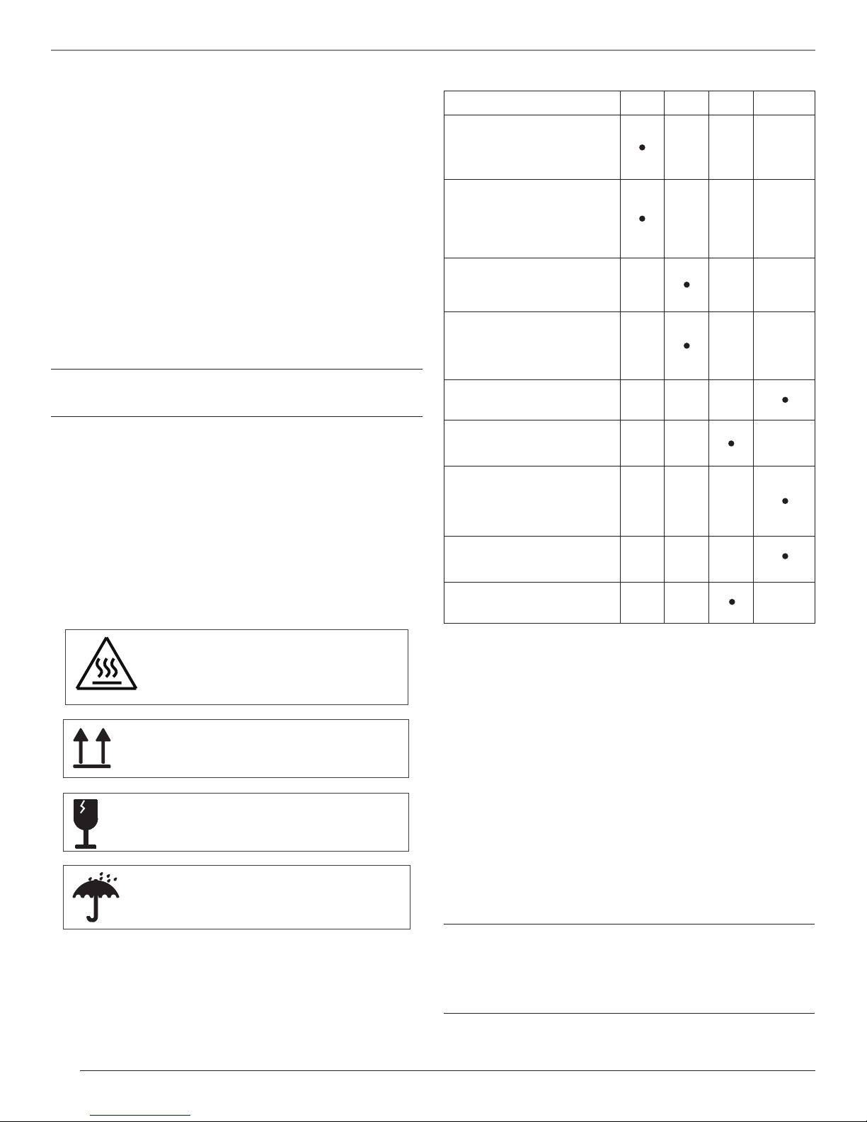
WARNING: To Avoid Serious Burns:
Do not touch surface during
operation.
Preventive maintenance
Weekly
Drain condensate from air receiver. If
equipped with autodrain, this will take
place automatically, however, drain
bottle has to be emptied.
If compressor is fitted with outlet filter,
check and empty for water by pressing
the black button at the bottom. If fitted
with autodrain, this will take place
automatically.
Check motor, air tubes, hoses and
equipment for leaks, and check the
pumping time.
Clean unit or wipe with a soft, damp
cloth. If necessary, use paraffin on rag
to remove sticky adhesions. Dust and
dirt prevent cooling.
Check intake filter. Clean or replace if
necessary. Minimum every 2000 hours
Replace silencer (intake filter), if
necessary
Check the O-ring in the non-return
valve and replace, if necessary.
Note! Empty receiver of air before
dismounting.
Check filter regulator, clean or replace
as neccessary
Test the safety valve by gently pulling
the ring with pressure in the receiver.
Filters and non-return valves should be serviced every 2000 hours. The JUN-AIR basic service kit (identified in the accessories
portion of this manual) can be purchased to accommodate.
The comprehensive service kit includes components to maintain the system’s compressor (cups, valves, o-rings, cylinders) as well as
the systems filter elements, unloader valve, silencer, & NRV.
Comprehensive service kits should be utilized every 8000 hours.
Any solenoid accessories on the system should be serviced every 12000 hours.
Monthly Annually 2000 Hours
Indicates package should be handled with
these symbols pointing up.
FRAGILE: Handle package with care.
Indicates this package must be kept dry.
6
Check the Pumping Time
The pumping time indicates the condition of the compressor provided that
there are no leaks in the system where the compressed air may leak. Test the
compressor as follows:
1. Empty the air receiver of compressed air ( the pressure gauge shows 0 Bar)
2. Close the outlet on the air receiver and check that the drain cock is closed.
3. Start the compressor and note how long it takes until it switches off.
Ensure that the pressure in the air receiver is 8bar/120 psi as deviations may
indicate the wrong results (see technical Specifications for pumping time)
Important!
Always test the compressor when cold as the time indicated
refers to the pumping time of a cold compressor. The pumping
time of a warm compressor is much longer and consequently,
the result would be misleading.
© 2015, JUN-AIR
We reserve the right to make any alterations which may be due to any technical improvements
Printed in the USA

86/87R Compressor System User Guide 6190755 (Rev A)
Pressure vessel
Pressure tested at: All sizes:
Directions for use
Application Receiver for compressed air.
Receiver specifications See name plate.
Installation Tubes, etc. must be installed with
suitable materials.
Placement Observe the working temperature
of the receiver.
Ensure sufficient room for inspection
and maintenance.
The receiver must be kept in a
horizontal position.
Corrosion protection The surface treatment must be
maintained as required.
Internal inspection at least every
5 years.
Drain condensate at least once a week.
Alternation/repair No welding must be made on
pressurised parts.
Safety valve Ensures that PS rating will not be
exceeded.
Never adjust to a higher pressure
than PS.
The capacity of the valve must be
calculated in accordance with the
volume of air supplied by the
compressor.
(PS = Maximum working pressure
of the receiver. This is specified on the
system's serial number label.)
16.5 - 24BAR
© 2015, JUN-AIR
We reserve the right to make any alterations which may be due to any technical improvements
Printed in the USA
7
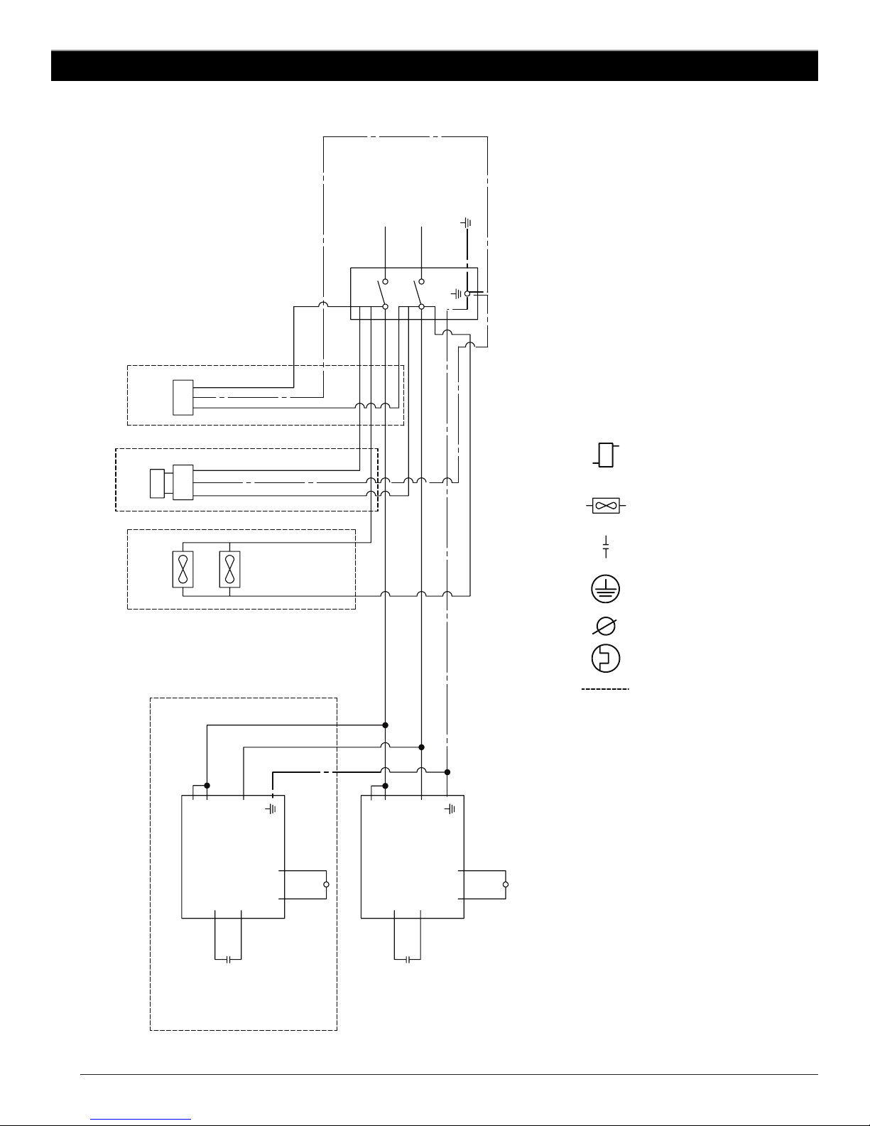
PROJECTION:
JUN-AIR
JUN-AIR
B
TLB
2
3
WEIGHT:
MATERIAL:
PROJECT NO:
TITLE
MADE FROM:
DG
8/7/14
APPROVED
DRAWN
B
SIZE
1 OF 1
DRAWING NUMBER
XB6782
SCALE
1:1
A
SHEET
REV
6
5
4
7
8
GAST /
PROPRIETARY INFORMATION
THIS DRAWING EMBODIES A PROPRIETARY DESIGN
OWNED BY IDEX,INC. AND IS SUBMITTED UNDER A
CONFIDENTIAL RELATIONSHIP. EXCEPT USES EXPRESSLY
GRANTED IN WRITING, ALL RIGHTS ARE RESERVED BY IDEX
INC.
COPYRIGHT © 2007 IDEX INC.
08/7/2014
-----
DATE
ECN
GEOMETRIC TOLERANCING PER: ASME Y14.5M-1994
DO NOT SCALE DRAWING
BY
DG
TOLERANCES UNLESS OTHERWISE SPECIFIED
WHERE USED:
SOURCE CODE:
ELECTRICAL DRAWING 87R BASICS 120V
YELLOW/GREEN
(GREEN)
BLUE
PRESSURE SWITCH
BROWN
BLUE
BROWN
GROUND
(N)
(L1)
ORANGE
RED
YELLOW
BROWN
30
μF
CAPACITOR
M
L
IN
OUT
MOTOR 1
WHITE
BLUE
COOLER
BOX
AUTOMATIC
DRAIN
PRESSURE
RELIEF
30
μF
CAPACITOR
MOTOR 2
BLACK
INSULATE
GREEN
GREEN
INSULATE
(N)
(L1)
ORANGE
RED
YELLOW
BROWN
WHITE
BLUE
BLACK
1
2 3
4
5
6
6190755 (Rev A) 86/87R Compressor System User Guide
86/87R- XB Wiring Schematics
120VAC - 60Hz
PRESSURE
RELIEF
IN
(L1)
BLACK
L
M
120V/60Hz
(L2)
WHITE
YELLOW/GREEN
PRESSURE SWITCH
Legend
IN
: AUTO DRAIN
OUT
AUTOMATIC
DRAIN
OUT
: FAN
:CAPACITOR
COOLER
BOX
(L2)
(L1)
BLUE
WHITE
BLACK
MOTOR 2
RED
MOTOR 1
BLACK
BLUE
(L1)
BLACK
WHITE
(L2)
WHITE
(GREEN)
GROUND
RED
:EARTH
:TERMINAL CLIP
:MOTOR PROTECTION
:ADDITIONAL FEATURES
BROWN
YELLOW
30 μFCAPACITOR
ORANGE
8
YELLOW
ORANGE
BROWN
30 μFCAPACITOR
© 2015, JUN-AIR
We reserve the right to make any alterations which may be due to any technical improvements
Printed in the USA
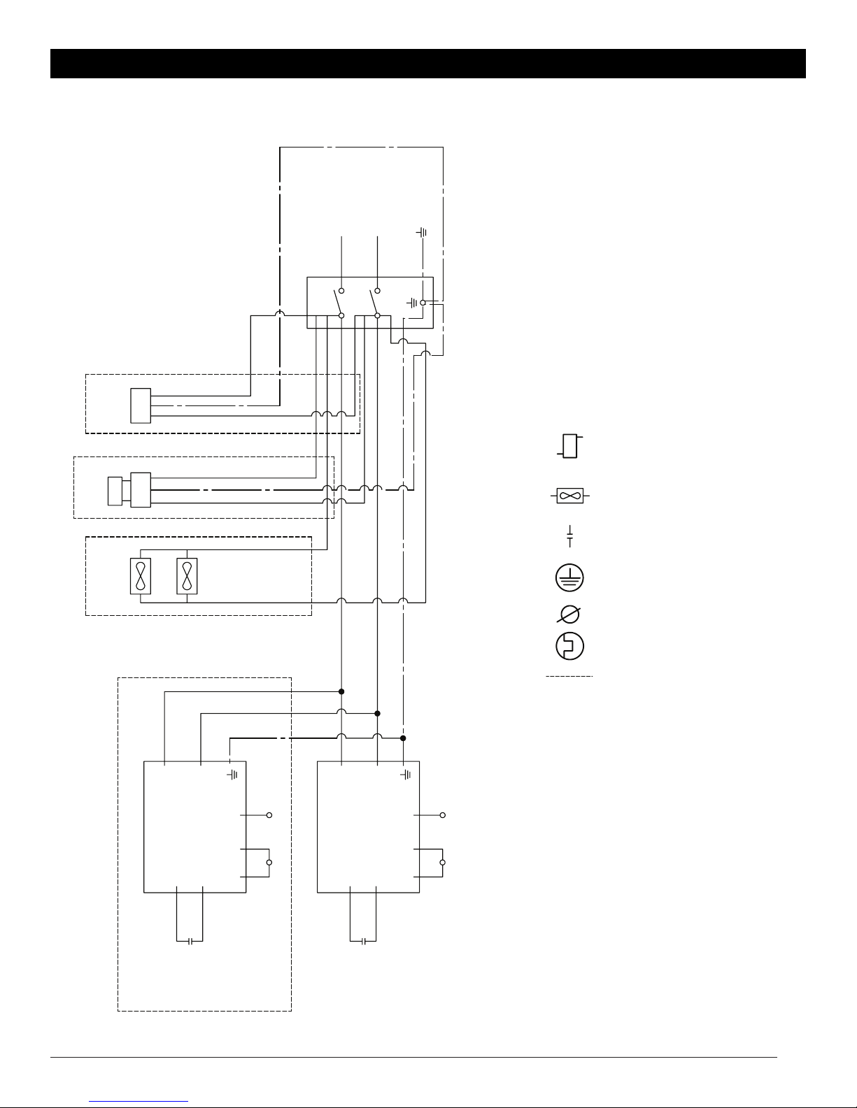
PROJECTION:
JUN-AIR
JUN-AIR
B
TLB
3
C
A
B
WEIGHT:
MATERIAL:
PROJECT NO:
TITLE
MADE FROM:
DG
DG
8/7/14
APPROVED
DRAWN
B
SIZE
1 OF 1
DRAWING NUMBER
XB6790
SCALE
1:1
A
SHEET
REV
D
6
5
4
7
8
E
F
GAST /
PROPRIETARY INFORMATION
THIS DRAWING EMBODIES A PROPRIETARY DESIGN
OWNED BY IDEX,INC. AND IS SUBMITTED UNDER A
CONFIDENTIAL RELATIONSHIP. EXCEPT USES EXPRESSLY
GRANTED IN WRITING, ALL RIGHTS ARE RESERVED BY IDEX
INC.
COPYRIGHT © 2007 IDEX INC.
08/7/2014
-----
DATE
ECN
GEOMETRIC TOLERANCING PER: ASME Y14.5M-1994
08/15/2014
DO NOT SCALE DRAWING
BY
DG
TOLERANCES UNLESS OTHERWISE SPECIFIED
WHERE USED:
SOURCE CODE:
ELECTRICAL DRAWING 87R BASICS 230V
YELLOW/GREEN
(GREEN)
BLUE
PRESSURE SWITCH
BROWN
BLUE
BROWN
GROUND
(N)
(L1)
ORANGE
RED
YELLOW
BROWN
30
μF
CAPACITOR
M
L
IN
OUT
MOTOR 1
WHITE
BLUE
COOLER
BOX
AUTOMATIC
DRAIN
PRESSURE
RELIEF
30
μF
CAPACITOR
MOTOR 2
BLACK
INSULATE
GREEN
GREEN
INSULATE
(N)
(L1)
ORANGE
RED
YELLOW
BROWN
WHITE
BLUE
BLACK
1
2 3
4
5
6
86/87R Compressor System User Guide 6190755 (Rev A)
86/87R- XB Wiring Schematics
120VAC / 230VAC - 50Hz or 60Hz
230V/50-60Hz
(N)
(L1)
BLUE
PRESSURE
RELIEF
AUTOMATIC
DRAIN
BROWN
L
M
IN
OUT
YELLOW/GREEN
PRESSURE SWITCH
Legend
IN
: AUTO DRAIN
OUT
: FAN
:CAPACITOR
COOLER
BOX
MOTOR 2
(N)
(L1)
WHITE
YELLOW
BLUE
BROWN
GREEN
ORANGE
RED
BLACK
INSULATE
MOTOR 1
BROWN
(L1)
WHITE
YELLOW
BLUE
(N)
BLUE
BROWN
(GREEN)
GROUND
GREEN
ORANGE
RED
BLACK
INSULATE
:EARTH
:TERMINAL CLIP
:MOTOR PROTECTION
:ADDITIONAL FEATURES
30 μFCAPACITOR
© 2015, JUN-AIR
We reserve the right to make any alterations which may be due to any technical improvements
Printed in the USA
30 μFCAPACITOR
9

6190755 (Rev A) 86/87R Compressor System User Guide
PROJECTION:
JUN-AIR
JUN-AIR
WEIGHT:
MATERIAL:
PROJECT NO:
TITLE
MADE FROM:
DG
TLB
8/7/14
APPROVED
DRAWN
B
SIZE
DRAWING NUMBER
XB6787
SCALE
A
SHEET
REV
GAST /
PROPRIETARY INFORMATION
THIS DRAWING EMBODIES A PROPRIETARY DESIGN
OWNED BY IDEX,INC. AND IS SUBMITTED UNDER A
CONFIDENTIAL RELATIONSHIP. EXCEPT USES EXPRESSLY
GRANTED IN WRITING, ALL RIGHTS ARE RESERVED BY IDEX
INC.
COPYRIGHT © 2007 IDEX INC.
08/7/2014
DATE
GEOMETRIC TOLERANCING PER: ASME Y14.5M-1994
08/15/2014
BY
DG
TOLERANCES UNLESS OTHERWISE SPECIFIED
WHERE USED:
SOURCE CODE:
PNEUMATICS DRAWING 86/87R BASICS
COMPRESSED AIR OUTLET
TO WASTE
TO WASTE
M
M
2x 86/87R
TANK
PRESSURE
REGULATED
PRESSURE
FILTER
5
μm
1
2 3
4
5
6
7
86/87R- XB Pneumatic Schematic
M
2x 86/87R
M
TO WASTE
Legend
:WORKING PIPE
:STEERING PIPE
:PIPE COUPLING
M
:COMPRESSOR
:TANK
:INLET FILTER
:PRESSURE GAUGE
:PRESSURE SWITCH
TANK
PRESSURE
REGULATED
PRESSURE
μm
FILTER
5
TO WASTE
:SAFETY VALVE
:NON RETURN VALVE
:FILTER MANUAL DRAIN
:VALVE FOR PRESSURE RELIEF
:REDUCTION VALVE
:VALVE
:MUFFLER
:FILTER WITH AUTOMATIC DRAIN
:OPTIONAL
:TIMED AUTO DRAIN
:2/2 PRESSURE RELIEF
10
COMPRESSED AIR OUTLET
We reserve the right to make any alterations which may be due to any technical improvements
© 2015, JUN-AIR
Printed in the USA

86/87R Compressor System User Guide 6190755 (Rev A)
DATE
DESCRIPTION
PART NUMBER
1760420 - EXPLODED
SHEET 1 OF 1
REFERENCE ONLY
2/20/2015
1760420
86R-4B 230V/50Hz CE
86/87R- XB Exploded Views
86R-4B 230V - 50Hz
6341101
6973090
6973105
6975002
7164200
5416100
5418000
5130000
4071039
6340500
3051000
7024002
6243710 O-RING
86R135-101T-N270X
6341800
6357100
7540000
5960000
B
5427002
5427003
A
5031000
B
7190000
7071000
A
7565000
5414500
5424000
5427001
7156000
5130000
6290200
B300A
5237700
6341800
6355000
8008302
6390025
6320200
A-A 6457020
B-B 6420000
5320226
COMPLETE
6253704
6252010
5935011
6372700
© 2015, JUN-AIR
We reserve the right to make any alterations which may be due to any technical improvements
Printed in the USA
6320200
6296850
6253000
6390000
6314000
6392145
11

6190755 (Rev A) 86/87R Compressor System User Guide
DATE
DESCRIPTION
PART NUMBER
1760421 - EXPLODED
SHEET 1 OF 1
REFERENCE ONLY
1760421
86R-4B 230V/60Hz UL
86/87R- XB Exploded Views
86R-4B 120V/230V - 60Hz
5130000
6293100
6294600
6341101
6973090
6973105
6975002
7164200
5417000
5418000
B
5427002
5427003
B
6294600
6293100
5075000
7190000
A
7071000
7565000
5414500
5424000
5427001
7156000
5237700
4071039
6340500
3050005
7024002
6243710 O-RING
86R135-101T-N270X
6341800
6357100
7540000
5960000
6253704
6252010
5935011
6372700
5130000
6341800
6355000
8008302
6390025
6320200
6290200
A
A-A 6457020
B-B 6420000
B300A
6253000
6390000
6314000
6392145
5320226
COMPLETE
6320200
6296850
12
We reserve the right to make any alterations which may be due to any technical improvements
© 2015, JUN-AIR
Printed in the USA

86/87R Compressor System User Guide 6190755 (Rev A)
DATE
DESCRIPTION
PART NUMBER
1760400 - EXPLODED
SHEET 1 OF 1
REFERENCE ONLY
2/20/2015
1760400
87R-4B 230V/50Hz CE
86/87R- XB Exploded Views
87R-4B 230V - 50Hz
5130000
4071039
6341101
6973090
6973105
6975002
7164200
5416100
5418000
6340500
3051000
5031000
B
5427002
5427003
B
7190000
7071000
A
7565000
5414500
5424000
5427001
7156000
5237700
5130000
6341800
6355000
8008302
6390025
6320200
6290200
B300A
87R642-104RT-N470X
6341800
6357100
7540000
5960000
6253704
6252010
5935012
6372700
A
6390000
6314000
A-A 6457028
B-B 6420000
5320226
COMPLETE
7024002
6243710 O-RING
6320200
6296850
6253000
© 2015, JUN-AIR
We reserve the right to make any alterations which may be due to any technical improvements
Printed in the USA
13

6190755 (Rev A) 86/87R Compressor System User Guide
DATE
DESCRIPTION
PART NUMBER
1760401 - EXPLODED
SHEET 1 OF 1
REFERENCE ONLY
1760401
87R-4B 230V/60Hz UL
86/87R- XB Exploded Views
87R-4B 120V/230V - 60Hz
6293100
6294600
6341101
6973090
6973105
6975002
7164200
5417000
5418000
5130000
B
5427002
5427003
B
6294600
6293100
5075000
7190000
A
5424000
5427001
7156000
7071000
7565000
5414500
5237700
4071039
6340500
3050005
87R642-104RT-N470X
6341800
6357100
7540000
5960000
6253704
6252010
5935012
6372700
5130000
6290200
A
6390000
6314000
6341800
6355000
8008302
6390025
6320200
B300A
A-A 6457028
B-B 6420000
5320226
COMPLETE
7024002
6243710 O-RING
6320200
6296850
6253000
14
We reserve the right to make any alterations which may be due to any technical improvements
© 2015, JUN-AIR
Printed in the USA

86/87R Compressor System User Guide 6190755 (Rev A)
DATE
DESCRIPTION
PART NUMBER
1760430 - EXPLODED
SHEET 1 OF 1
REFERENCE ONLY
1760430
87R-15B 230V/50Hz CE
86/87R- XB Exploded Views
87R-15B 230V - 50Hz
B300A
6253704
5427001
5427002
5130000
4071039
5427003
6340500
A-A 6457020
8111962
6346300
7156100
5130000
5414500
7566200
7180000
7566000
7024002
A
6243710 O-RING
6290200
5424000
A
5340000
6296850
5935012
6392145
6296851
6392145
87R642-104RT-N470X
5237700
6341800
6355000
8008302
6390025
6320200
6392350
6392202
7540000
B
B
5960000
6372700
7020002
6243715 O-RING
7025005
6243715 O-RING
7070000
5031000
6341101
7190000
6973090
6975002
B-B 6420000
5419500
© 2015, JUN-AIR
We reserve the right to make any alterations which may be due to any technical improvements
Printed in the USA
5416100
7180000
7071350
7566000
3210005
6250000
15

6190755 (Rev A) 86/87R Compressor System User Guide
DESCRIPTION
PART NUMBER
1760431 - EXPLODED
SHEET 1 OF 1
REFERENCE ONLY
1760431
87R-15B 230V/60Hz UL
86/87R- XB Exploded Views
87R-15B 120V/230V - 60Hz
A
B300A
6253704
5427001
5427002
5130000
4071039
5427003
6340500
A-A 6457020
B-B 6420000
8111962
6346300
7156100
5130000
5414500
7566200
7180000
7566000
6290200
7024002
6243710 O-RING
5424000
B
A
B
5340000
6296850
5935012
6392145
6392145
87R642-104RT-N470X
6296851
5237700
6341800
6355000
8008302
6390025
6320200
6392350
6392202
7540000
5960000
6372700
7020002
6243715 O-RING
7025005
6243715 O-RING
7070000
5075000
6293100
6294600
6341101
7190000
6973090
6975002
5417000
5419500
16
7180000
7071350
7566000
3210098
6250000
© 2015, JUN-AIR
We reserve the right to make any alterations which may be due to any technical improvements
Printed in the USA

86/87R Compressor System User Guide 6190755 (Rev A)
DATE
DESCRIPTION
PART NUMBER
1760410 - EXPLODED
SHEET 1 OF 1
REFERENCE ONLY
1760410
87R-25B 230V/50Hz CE
86/87R- XB Exploded Views
87R-25B 230V - 50Hz
B300A
6253704
5427001
5427002
5130000
4071039
5427003
6340500
A-A 6457020
B-B 6420000
8111962
6346300
7156100
5130000
5414500
7566200
7180000
7566000
5420000
7024002
A
6243710 O-RING
6290200
5424000
A
5340000
6296850
B
B
5935012
6392145
6296851
6392145
87R642-104RT-N470X
5237700
6341800
6355000
8008302
6390025
6320200
6392350
6392202
7540000
5960000
6372700
7020002
6243715 O-RING
7025005
6243715 O-RING
7070000
5031000
6341101
7190000
6973090
6975002
5416100
7180000
7071350
7566000
© 2015, JUN-AIR
We reserve the right to make any alterations which may be due to any technical improvements
Printed in the USA
3410010
6250000
17

6190755 (Rev A) 86/87R Compressor System User Guide
6290200
DATE
DESCRIPTION
PART NUMBER
1760411 - EXPLODED
SHEET 1 OF 1
REFERENCE ONLY
1760411
87R-25B 230V/60Hz UL
86/87R- XB Exploded Views
87R-25B 120V/230V - 60Hz
A
B300A
6253704
5427001
5427002
5130000
4071039
5427003
6340500
A-A 6457020
B-B 6420000
8111962
6346300
7156100
5130000
5414500
7566200
7180000
7566000
5420000
7024002
6243710 O-RING
5424000
B
A
B
5340000
6296850
5935012
6392145
6392145
87R642-104RT-N470X
6296851
5237700
6341800
6355000
8008302
6390025
6320200
6392350
6392202
7540000
5960000
6372700
7020002
6243715 O-RING
7025005
6243715 O-RING
7070000
5075000
6293100
6294600
6341101
7190000
6973090
6975002
5417000
7180000
7071350
7566000
18
3411399
6250000
© 2015, JUN-AIR
We reserve the right to make any alterations which may be due to any technical improvements
Printed in the USA

86/87R Compressor System User Guide 6190755 (Rev A)
Parts & Accessories List
Part no. Description
4071030 5 micron outlet filter/regulator with manual drain
4071055 .01 micron outlet filter with manual drain
4071065 FILTER 0.01UM W/AUTODRAIN
4071210 SPARE PARTS KIT F/5micron Filter
4071220 SPARE PARTS KIT Regulator
4071230 SPARE PARTS KIT Filter/Regulator
4071240 SPARE PARTS KIT F/0.01micron Filter
4797100 Tank Auto Drain kit with drain bottle 120V
4900001 NON RETURN VALVE KIT
5471005 86/87R-XB Basic Service Kit
5471006 87R-XB Comprehensive Service Kit
5471007 86R-4B Comprehensive Service Kit
5612300 Drain Bottle Kit
4797600 Tank Auto Drain kit with drain bottle 230V
86R135-101-N270X 86R135-101T-N270X: 86R-4B Compressor individually packaged for resale
87R642-103R-N470X 87R642-104RT-N470X: 87R-XB Compressor individually packaged for
resale
© 2015, JUN-AIR
We reserve the right to make any alterations which may be due to any technical improvements
Printed in the USA
19

6190755 (Rev A) 86/87R Compressor System User Guide
Part no. Description
3050005 TANK - 4L CE/UL w/inspection
3051000 4L TANK CE
3210005 TANK - 15B CE
3210098 Tank – 15B CE/ASME 16 Bar
3410010 TANK - 25B CE
3411399 TANK - 25B ASME
4071039 Filter regulator 5u w/automati
4141800 RAPID FITTING ELBOW 1/8"XO6
4146457 RAPID FITTING 06-06MM PIPE
5031000 Pressure switch MDR 2/11
5075000 Pressure switch MDR 21/11 UL
5130000 GAUGE +40 - 0-16BAR 1/8"DOWN
5237700 CAPACITOR 30UF/370V AC
5320226 Handle 86/87R-4B
5340000 Handle 87R-25/15B
5414500 Non return valve f/lubicated
5416100 SAFETY VALVE 12 BAR 177 PSI
5417000 SAFETY VALVE 9 BAR/135 PSI
5418000 DRAIN COCK 1/4" 4L
5419500 DRAIN COCK 1/4" 15L
5420000 DRAIN COCK 1/4" 25L
5424000 OUTLET COCK 1/4"
5427001 Nipple for connecting Fil/reg
5427002 Nipple for connecting Fil/reg
5427003 Connector for Fil/reg
5935011 Squeeze Box 86R single
5935012 Squeeze Box 87R Dual
5960000 CABLE RELIEF
6243710 O-RING F/OF PLUG
6243715 O-ring O7x1, 5 Viton (for 1 /
6250000 SOCKET 25 MM BLACK
6253704 Rubber Base f/82R
6290200 PLASTIC HANDLE BLACK 025MM
6293100 NUT PG16 BRASS
6294600 PG-NIPPLE M16 UL/CSA
6296850 CABLE RELEIF HEYCO 1327 ELBOW
6296851 Cable relief Heyco 1226 OF300
*6314000 M6x10 HHCS ZINC PLATE
*6320200 COUNTER NUT M8 FLAT FZB
6340500 1/8 PIPE PLUG x 7mm LONG
*6341040 M4x25 SHCS ZINC PLATE
Part no. Description
*6341101 SCREW F/UNLOADER VALVE M5X6
*6341800 M6x10 SHCS
*6346300 M8x20 FLAT HEAD ZINC PLATE
*6355000 WASHER 6.5X13X1.25MM
*6357100 Washer O18xO6.4x1.6 FZB
*6372500 LOCK NUT M4
*6372700 LOCK NUT M8 FZB
*6390000 STAR WASHER TYPE A M6
*6390025 Star washer type A M8
*6391800 SCREW PH FZB 4X12
*6391900 M2.2x12 PAN HD SHEET MTL ZINC
*6392145 SCREW GROUND
*6392202 M6 x 12MM FLAT HEAD ZINC
*6392350 M8x25 FLAT HEAD ZINC
6420000 FLEX PIPE 1/8" 20 (22)
6457020 Teflon hose 1/4" 20 cm with el
6457024 Teflon hose 1/4" 24 cm with el
6457028 Teflon hose 1/4" 28 cm with el
**6973090 Unloader valve
**6973105 Needle f/unloader valve 16.4 m
**6975002 Silencer f/unload valve OF300
7020002 Double nipple 1/8" w/o-ring
7024002 Double nipple 1/4 in w/o-ring
7025000 DOUBLE NIPPLE 1/4"X1/8"
7025005 Double nipple 1/4"x1/8" w/o-ri
7070000 CONN. PIECE F/NON-RETURN VALVE
7071000 T-PIECE 1/8"
7071350 Tee-connector 1/4" (2xexternal
7156000 EXTENSION PIECE F/COCK SHORT
7156100 EXTENSION PIECE F/COCK LONG
7164200 CROSS CONNECTOR
7180000 ELBOW 1/4" INT/EXT KRG
7190000 ELBOW 1/8"
7540000 BUSH F/5960000
7555000 Coupling nut 1/8"
7565000 BUSHING 1/4"EXT X 1/8"INT
7566200 BUSHING 1/4"X1/4" L = 35 MM
8008302 BRACKET
8111962 MOUNTING BRACKET F/ 87R-25B
B300A FILTER PLASTIC 1/4 NPT
* Not available for resale
** Only available in service kit
20
We reserve the right to make any alterations which may be due to any technical improvements
© 2015, JUN-AIR
Printed in the USA

86/87R Compressor System User Guide 6190755 (Rev A)
Technical Data & Specifications
Specifications
87R-25B 87R-15B
120 V 230 V 230 V 120 V 230 V 230 V
Frequency HZ 60 50 60 60 50 60
Displacement @ 0 Bar
FAD @ 8 bar
Max Current A 5,7 2,5 2,8 5,7 2,5 2,8
Weight
Pumping Time
0-8 bar/0-120psi
Noise level
Dimensions (LxWxH)
Motor
Max Pressure
Tank Size
Thermal Protection Yes Yes
Duty Cycle 100% 100%
Relative Humidity % 20 - 80%* 20 - 80%*
Ambient Temperature 5/40°C 5/40°C
l/min 91 82 91 91 82 91
CFM 3,2 2,9 3,2 3,2 2,9 3,2
l/min 34 28 34 34 28 34
CFM 1,2 1 1,2 1,2 1 1,2
kg 32 27 32 29 22 29
lbs 70 59 70 61 48,5 61
sec 185 205 185 115 125 115
dB(a)/1m
mm
in
63 61 63 63 61 63
388 x 380 x 619
15,3 x 15,0 x 24,4
388 x 380 x 548
15,3 x 15,0 x 21,6
HP 1/2 1/2
KW 0,37 0,37
bar 8 8
psi 120 120
liters 25 15
gallons 6,6 4
* Non-Condensing
The figures in the tables are based on the unit working in a clean environment at an ambient
temperature of 20°C, relative humidity of 50% and operating at sea level. The performance of the
product will be adversely effected at high altitudes. JUN-AIR reserves the right to make technical
modifications to these units as needed.
© 2015, JUN-AIR
We reserve the right to make any alterations which may be due to any technical improvements
Printed in the USA
21

6190755 (Rev A) 86/87R Compressor System User Guide
Specifica-
tions
Frequency HZ 60 50 60 60 50 60
l/min 91 82 91 40 34 40
Displacement @
0 Bar
FAD @ 8 bar
Max Current A 5,7 2,5 2,8 2,1 1,7 1,1
Weight
Pumping Time
0-8 bar/0-120psi
Noise level
Dimensions
(LxWxH)
Motor
Max Pressure
Tank Size
Thermal Protection Yes Yes
Duty Cycle 100% 100%
Relative Humidity % 20 - 80%* 20 - 80%*
Ambient Temperature 5/40°C 5/40°C
CFM 3,2 2,9 3,2 1,41 1,20 1,41
l/min 34 28 34 15,0 12,5 15,0
CFM 1,2 1 1,2 0,53 0,44 0,53
kg 18 18 18 15,6 15,6 15,6
lbs 40 40 40 34,4 34,4 34,4
sec 32 37 32 80 90 80
dB(a)/1m
mm
in
HP 1/2 1/3
KW 0,37 0,25
bar 8 8
psi 120 120
liters 4 4
gallons 1,1 1,1
120 V 230 V 230 V 120 V 230 V 230 V
63 61 63 58 55 58
87R-4B 86R-4B
404 x 306 x 338
15,9 x 12,0 x13,3
404 x 306 x 338
15,9 x 12,0 x13,3
* Non-Condensing
The figures in the tables are based on the unit working in a clean environment at an ambient
temperature of 20°C, relative humidity of 50% and operating at sea level. The performance of the
product will be adversely effected at high altitudes. JUN-AIR reserves the right to make technical
modifications to these units as needed.
22
We reserve the right to make any alterations which may be due to any technical improvements
© 2015, JUN-AIR
Printed in the USA

86/87R Compressor System User Guide 6190755 (Rev A)
86R-4B-BXXXX English Performance
1.6
1.4
1.2
1.0
0.8
Flow (CFM)
0.6
0.4
0.2
0.0
0 20 40 60 80 100 120
Pressure (PSI)
86R-4B-BXXXX Metric Performance
45
40
35
50 Hz
60 Hz
30
25
20
Flow (LPM)
15
10
5
0
0 1 2 3 4 5 6 7 8 9
© 2015, JUN-AIR
We reserve the right to make any alterations which may be due to any technical improvements
Printed in the USA
50 Hz
60 Hz
Pressure (BAR)
23

6190755 (Rev A) 86/87R Compressor System User Guide
87R-XB-JXXXX English Performance
3.5
3.0
2.5
2.0
50 Hz
1.5
Flow (CFM)
1.0
0.5
60 Hz
0.0
0 20 40 60 80 100 120
Pressure (PSI)
87R-XB-JXXXX Metric Performance
100
90
80
70
60
50
Flow (LPM)
40
30
20
50 Hz
60 Hz
10
0
0 1 2 3 4 5 6 7 8 9
24
Pressure (BAR)
© 2015, JUN-AIR
We reserve the right to make any alterations which may be due to any technical improvements
Printed in the USA

86/87R Compressor System User Guide 6190755 (Rev A)
87R - 25 B Q2 - X XX X X X
Tank
Regulatory
Elec/region config
Accessory configuration
Compressor Configuration
Dryer Type
Enclosure Style
Receiver Size
Family & cylinders
Family & cylinders Receiver Size Enclosure Style Dryer Type
86R = single cylinder & small bore (low flow) 4, 15, 25, 40 B = Basic or Open Q = iQ dryer (2, 3, or 6 size)
87R = twin cylinder & large bore (high flow) M = Metal Cabinet A = Membrane Dryer
P = Plastic Cover
Compressor Accessory Elec/region config Regulatory Tank
A Single Cylinder, Low Stroke Manual tank drain, 5µ F/R manual drain,
B Single Cylinder, High Stroke (0.35") Manual tank drain, 5µ F/R auto drain,
C Single Cylinder, High Stroke (0.42") Bent
Valve (100psi max)
D Manual tank drain, 5µ F/R auto drain,
E Manual tank drain, 5µ F/R auto drain, no
F Manual tank drain, 5µ F/R auto drain,
G Dual Parallel Cylinder, Low Stroke 220-240 50 or 60 AU (AS-3112) ASME/CRN
H Dual Parallel Cylinder, High Stroke
(0.37")
J Dual Parallel Cylinder, High Stroke
(0.42") Bent Valves
K Auto tank drain, 5µ F/R auto drain, with
L Auto tank drain, 5µ F/R auto drain,
M Auto tank drain, 5µ Filter auto drain,
N Dual Staged Cylinders, Std Stroke Auto tank drain, 5µ Filter auto drain,
P Dual Independent Cylinders, Std Stroke
R
S Special compressor configuration OEM Specific Model Special voltage/plug Special Special
no bottle, pressure switch unloader
with bottle
Manual tank drain, 5µ F/R manual drain,
0.01µ Coalescing Filter, no bottle
0.01µ Coalescing Filter, with bottle
bottle, pressure switch unloader
0.01µ Coalescing Filter, no bottle
bottle
0.01µ Coalescing filter, with bottle
regulator, solenoid unloader, no bottle
regulator, solenoid unloader, with bottle
100/50 or 60 Japan
(NEMA 1-15 or 5-15)
120/50 or 60 NA (NEMA 5-15) CSA ASME
220-240 50 or 60 NA (NEMA 6-15) cULus ASME
220-240 50 or 60 EU (CEE 7/7) CE/cULus GB (china)
220-240 50 or 60 EU (CEE 7/7) &
GB adaptor
220-240 50 or 60 CH (NEMA 1-15
or AS-3112)
220-240 50 or 60 GB (IEC Type G) CE/UL
CE CE
Singapore
CCC CRN
cCSAus ASME/CE
None
© 2015, JUN-AIR
We reserve the right to make any alterations which may be due to any technical improvements
Printed in the USA
25

6190755 (Rev A) 86/87R Compressor System User Guide
Pictures / Illustrations References
Pressure Switch ’1’ on or ’0’ off Pressure Switch Adjustment
Safety Valve Non-Return Valve
B
A
Non-Return Valve Assembly ( A + B + C)
C
26
We reserve the right to make any alterations which may be due to any technical improvements
© 2015, JUN-AIR
Printed in the USA

86/87R Compressor System User Guide 6190755 (Rev A)
WARRANTY POLICY
If within the warranty time limits described below, the compressor system or any of its components fail under normal use and service, the original user-owner must contact an authorized JUN-AIR dealer with the product sale and service records. Should the dealer not be
able to complete the repair, the dealer may contact JUN-AIR for disposition. The product’s
model and serial number, the installation date and the JUN-AIR invoice number must be furnished. Transportation charges both ways must be paid by the dealer. If upon receipt at the
factory, an examination reveals faulty or defective original parts, materials, or workmanship,
JUN-AIR will, at its sole discretion, rebuild or replace. This warranty does not cover damages
caused by misuse, abuse, accident, or neglect. Unauthorized alterations or repairs made
outside our factory will cancel this warranty and charges for them will not be allowed.
COMPRESSOR SYSTEMS
All compressor systems sold and installed by authorized JUN-AIR dealers are warrantied to
be free from defects in parts, workmanship, and materials for 8,000 hours of operation or
two (2) years from date of purchase, whichever occurs first.
This warranty excludes normal expected service items such as but not limited to: filters/filter
kits, o-rings, and hoses. It also excludes add-on accessories that carry their own specific
manufacturer’s warranty.
Gast Manufacturing
P.O. Box 97
2300 M139 Highway
Benton Harbor, MI 49023-0097
Ph: 269-926-6171
Fax: 269-925-8288
Gast Group Limited
c/o IDEX Trading (Shanghai) Co., LTD
Room 3502-3505
No. 1027 Chang Ning Road,
Zhaofeng Plaza
Shanghai, China 200050
Phone +86-21-52415599
Fax +86-21-52418339
Gast Group Ltd.
Unit 11, The I O Centre
Nash Road
Redditch, B98 7AS
United Kingdom
Phone +44 (0)1527-504040
Fax +44 (0)1527-525262
www.JUN-AIR.com
© 2015, JUN-AIR
We reserve the right to make any alterations which may be due to any technical improvements
Printed in the USA
27
 Loading...