

JUMO Quantrol LC100/LC200/LC300
Universal PID Controller Series
B 702030.0
Operating Manual
2013-09-23/00600571


Content
1 Introduction . . . . . . . . . . . . . . . . . . . . . . . . . . . . . . . . . . . . . . . . . . . . . . . . 5
1.1 Device documentation . . . . . . . . . . . . . . . . . . . . . . . . . . . . . . . . . . . . . . . . . . . . . . . . . . 5
1.2 Safety information . . . . . . . . . . . . . . . . . . . . . . . . . . . . . . . . . . . . . . . . . . . . . . . . . . . . . .5
1.3 Scope of delivery . . . . . . . . . . . . . . . . . . . . . . . . . . . . . . . . . . . . . . . . . . . . . . . . . . . . . .6
2 Installation - Electrical Connection . . . . . . . . . . . . . . . . . . . . . . . . . . . . . 7
2.1 Identifying the device version . . . . . . . . . . . . . . . . . . . . . . . . . . . . . . . . . . . . . . . . . . . . . 7
2.2 Excerpt from the technical data . . . . . . . . . . . . . . . . . . . . . . . . . . . . . . . . . . . . . . . . . . . 7
2.3 Installation . . . . . . . . . . . . . . . . . . . . . . . . . . . . . . . . . . . . . . . . . . . . . . . . . . . . . . . . . . . . 9
2.4 Installation notes . . . . . . . . . . . . . . . . . . . . . . . . . . . . . . . . . . . . . . . . . . . . . . . . . . . . . .10
2.5 Electrical isolation . . . . . . . . . . . . . . . . . . . . . . . . . . . . . . . . . . . . . . . . . . . . . . . . . . . . .10
2.6 Connection diagram . . . . . . . . . . . . . . . . . . . . . . . . . . . . . . . . . . . . . . . . . . . . . . . . . . . 11
3 Operation - Configuration - Parameterization . . . . . . . . . . . . . . . . . . . 13
3.1 Operation . . . . . . . . . . . . . . . . . . . . . . . . . . . . . . . . . . . . . . . . . . . . . . . . . . . . . . . . . . . 13
3.1.1 Display and operating elements . . . . . . . . . . . . . . . . . . . . . . . . . . . . . . . . . . . . . . . . . . 13
3.1.2 Self-optimization, setpoint and manual mode . . . . . . . . . . . . . . . . . . . . . . . . . . . . . . . . 13
3.1.3 Ramp function/firing curve . . . . . . . . . . . . . . . . . . . . . . . . . . . . . . . . . . . . . . . . . . . . . . 13
3.1.4 Level concept . . . . . . . . . . . . . . . . . . . . . . . . . . . . . . . . . . . . . . . . . . . . . . . . . . . . . . . . 14
3.1.5 Operator level (OPr) . . . . . . . . . . . . . . . . . . . . . . . . . . . . . . . . . . . . . . . . . . . . . . . . . . .14
3.2 Configuration (ConF) . . . . . . . . . . . . . . . . . . . . . . . . . . . . . . . . . . . . . . . . . . . . . . . . . . 15
3.2.1 Analog input (InP) . . . . . . . . . . . . . . . . . . . . . . . . . . . . . . . . . . . . . . . . . . . . . . . . . . . . .15
3.2.2 Controller (Cntr) . . . . . . . . . . . . . . . . . . . . . . . . . . . . . . . . . . . . . . . . . . . . . . . . . . . . . . 16
3.2.3 Ramp function/firing curve (rAFC) . . . . . . . . . . . . . . . . . . . . . . . . . . . . . . . . . . . . . . . . 17
3.2.4 Limit value monitoring (Li1, Li2) . . . . . . . . . . . . . . . . . . . . . . . . . . . . . . . . . . . . . . . . . . 17
3.2.5 Timer (tFCt) . . . . . . . . . . . . . . . . . . . . . . . . . . . . . . . . . . . . . . . . . . . . . . . . . . . . . . . . . . 18
3.2.6 Outputs (OutL, OutA) . . . . . . . . . . . . . . . . . . . . . . . . . . . . . . . . . . . . . . . . . . . . . . . . . . 19
3.2.7 Binary functions (binF) . . . . . . . . . . . . . . . . . . . . . . . . . . . . . . . . . . . . . . . . . . . . . . . . . 20
3.2.8 Display and operation (diSP) . . . . . . . . . . . . . . . . . . . . . . . . . . . . . . . . . . . . . . . . . . . . 20
3.2.9 Interface (IntF) . . . . . . . . . . . . . . . . . . . . . . . . . . . . . . . . . . . . . . . . . . . . . . . . . . . . . . . 21
3.3 Parameterization (PArA) . . . . . . . . . . . . . . . . . . . . . . . . . . . . . . . . . . . . . . . . . . . . . . . . 22
4 Supplement . . . . . . . . . . . . . . . . . . . . . . . . . . . . . . . . . . . . . . . . . . . . . . . 23
4.1 Additional information about installation . . . . . . . . . . . . . . . . . . . . . . . . . . . . . . . . . . . . 23
4.1.1 Device representation including dimensions . . . . . . . . . . . . . . . . . . . . . . . . . . . . . . . . . 23
4.1.2 Cleaning the device front . . . . . . . . . . . . . . . . . . . . . . . . . . . . . . . . . . . . . . . . . . . . . . . 25
4.2 Additional information about the device functions . . . . . . . . . . . . . . . . . . . . . . . . . . . . . 26
4.2.1 Entries and operator prompting . . . . . . . . . . . . . . . . . . . . . . . . . . . . . . . . . . . . . . . . . . 26
4.2.2 Analog input . . . . . . . . . . . . . . . . . . . . . . . . . . . . . . . . . . . . . . . . . . . . . . . . . . . . . . . . . 27
4.2.3 Analog output . . . . . . . . . . . . . . . . . . . . . . . . . . . . . . . . . . . . . . . . . . . . . . . . . . . . . . . . 27
4.2.4 Ramp function and firing curve . . . . . . . . . . . . . . . . . . . . . . . . . . . . . . . . . . . . . . . . . . . 28
4.2.5 Timers . . . . . . . . . . . . . . . . . . . . . . . . . . . . . . . . . . . . . . . . . . . . . . . . . . . . . . . . . . . . . . 29
4.2.6 Limit value monitoring . . . . . . . . . . . . . . . . . . . . . . . . . . . . . . . . . . . . . . . . . . . . . . . . . . 30
3

Content
4.2.7 Self-optimization (TUNE) . . . . . . . . . . . . . . . . . . . . . . . . . . . . . . . . . . . . . . . . . . . . . . . 30
4.3 Error messages . . . . . . . . . . . . . . . . . . . . . . . . . . . . . . . . . . . . . . . . . . . . . . . . . . . . . . . 33
4.4 Technical Data . . . . . . . . . . . . . . . . . . . . . . . . . . . . . . . . . . . . . . . . . . . . . . . . . . . . . . .34
4
1 Introduction
1.1 Device documentation
Data sheet T 702030 (as a PDF document)
The data sheet contains general information about the device and forms the basis for planning
and purchase decision.
Brief instructions B 702030.7 (printed in DIN A6 format)
These brief instructions contain the most important information about installation, the electrical
connection as well as operation, parameterization and configuration of the device. The brief instructions are supplied with every device. For further information, please refer to the operating manual B 702030.0 available as a PDF document.
Operating manual B 702030.0 (as a PDF document)
This operating manual contains all information about installation, the electrical connection as well
as operation, parameterization and configuration of the device.
Interface description B 702030.2.0 (as a PDF document)
It contains information about the RS485 interface, the Modbus protocol and the communication
with other devices.
All PDF documents can be downloaded under www.jumo.net.
1.2 Safety information
This manual contains information that must be observed in the interest of your own safety and to
avoid damage to assets. This information is supported by symbols which are used in this manual
as follows.
Please read this manual before starting up the device. Keep the manual in a place accessible to
all users at all times.
All necessary settings are described in this manual. Manipulations not described in this manual
or expressly forbidden will jeopardize your warranty rights.
Warning signs
DANGER!
This symbol indicates that Injury or death caused by electrical shock can occur, if the
respective protective measures have not been taken.
CAUTION!
This symbol in combination with the signal word indicates that damage to assets or data
loss will occur if suitable precautions are not taken.
READ DOCUMENTATION!
This symbol – placed on the device – indicates that the associated device documentation has to be observed. This is necessary to recognize the kind of the
potential hazards as well as to take the measures to avoid them.
5

1 Introduction
?
Note signs
TIP!
This symbol refers to Important information about the product or its handling or additional
use.
REFERENCE!
This symbol refers to Further information in other sections, chapters or manuals.
1.3 Scope of delivery
• Controller (including seal and fastening elements)
• Brief instructions B 702030.7 in DIN A6 format
6
2 Installation - Electrical Connection
2.1 Identifying the device version
Basic type
702031 Quantrol LC100 (format 48 mm x 48 mm)
702032 Quantrol LC200 (format 48 mm x 96 mm, portrait format)
702034 Quantrol LC300 (format 96 mm x 96 mm)
All types including 1 analog input (universal), 1 binary input (for potential-free contact; can be used as an alternative to analog input 0 to 10 V), 1 relay output (N/O)
Basic type extension
8 Standard, with factory settings
9 Customer-specific programming (on request)
1234Options (3 and 4 not for LC100)
000011111 relay output (N/O)
22221 logic output
3 - - - 1 analog output (configurable)
- 4 - - 1 RS485 interface
Voltage supply
23 AC 110 to 240 V +10/-15 %, 48 to 63 Hz
25 AC/DC 20 to 30 V, 48 to 63 Hz
/- - Order code
702034 / 8 - 3412-23 Example
2.2 Excerpt from the technical data
Case
Case type Plastic case for panel mounting as per IEC 61554 (indoor use)
Dimensions (front) LC100: 48 mm x 48 mm; LC200: 48 mm x 96 mm (portrait format);
LC300: 96 mm x 96 mm
Panel cut-out LC100: 45 mm x 45 mm; LC200: 45 mm x 92 mm;
LC300: 92 mm x 92 mm
Minimum spacing
horizontal / vertical
Depth behind panel LC100: max. 95 mm; LC200/LC300: max. 80 mm
Ambient / storage
temperature range
Ambient conditions rel. humidity < 90% annual average, without condensation
LC100: 11 mm / 30 mm (65 mm with USB cable);
LC200/LC300: 22 mm / 30 mm (65 mm with USB cable)
-5 to +55 °C / -40 to +70 °C
7

2 Installation - Electrical Connection
Site altitude up to 2000 m above sea level
Operating position any
Protection type as per DIN EN 60529, at the front IP 65, at the rear IP 20
Weight (fully equipped) LC100: approx. 150 g; LC200: approx. 200 g;
LC300: approx. 300 g
Electrical data
Voltage supply (switch
mode PSU)
Electrical
safety
Power consumption max. 14 VA
Electrical connection on the rear via screw terminals; with core-end ferrule of a pipe
Conductor cross section fine-strand 0.25 to 1.5 mm
Tightening torque 0.5 Nm
Electromagnetic
compatibility
Interference emission Class A - Only for industrial use Interference immunity Industrial requirements
Setup interface USB socket, type Mini-B 5-pole
AC 110 to 240 V +10/-15 %, 48 to 63 Hz
AC/DC 20 to 30 V, 48 to 63 Hz
as per DIN EN 61010, part 1
overvoltage category III, pollution degree 2
shape, open cable lug or pin cable lug
2
as per DIN EN 61326-1
8
2 Installation - Electrical Connection
1.
2.
1.
3.
2.
3.
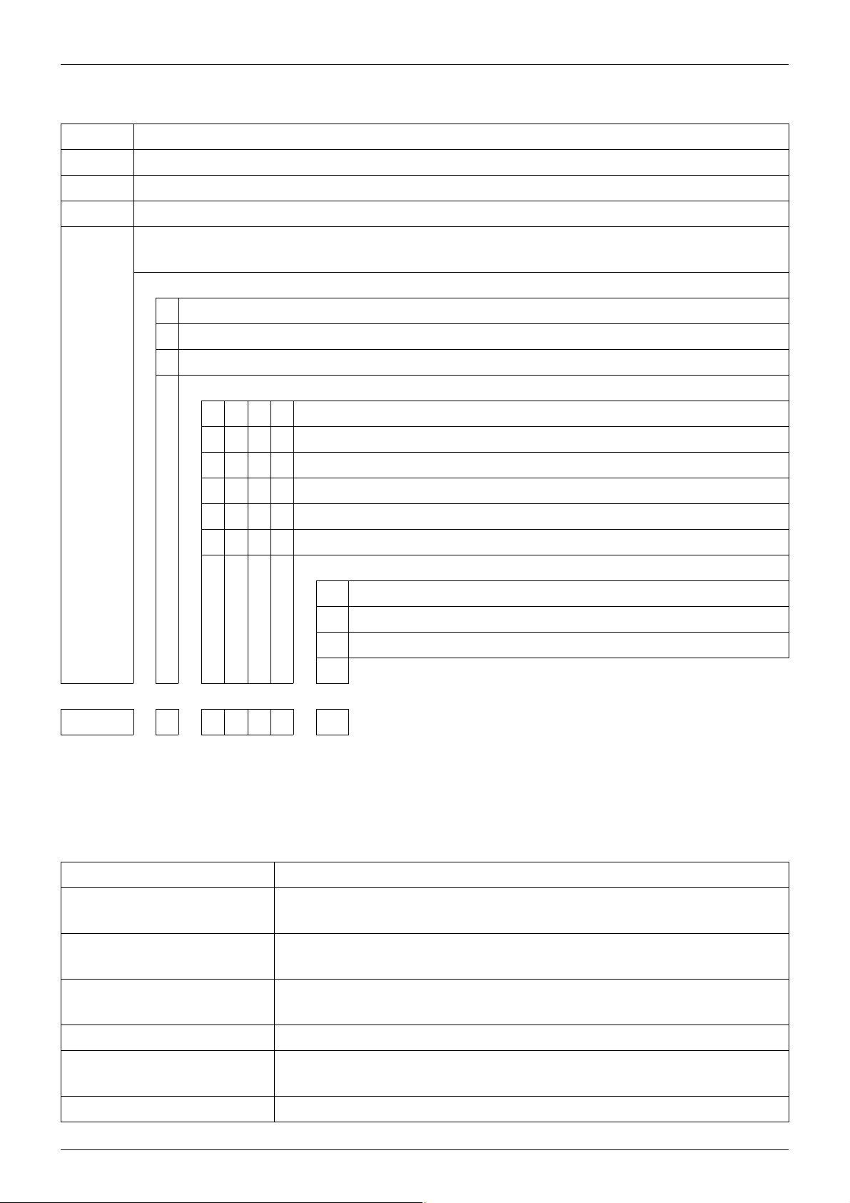
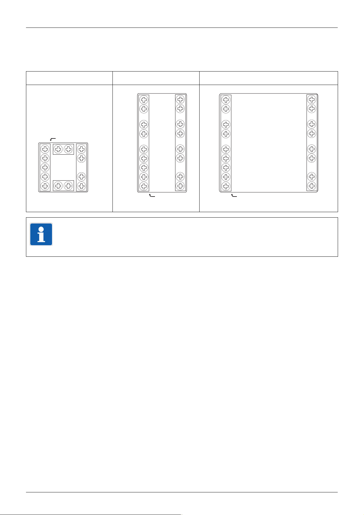
2.3 Installation
LC100 LC200 and LC300
Installation of LC100 Installation of LC200 and LC300
1. Insert the device from the front into the
panel cut-out and ensure that the seal is
correctly positioned.
2. Push the fastening frame from the panel
rear onto the device and press the
springs against the panel rear until the
lugs engage in their slots and it is
sufficiently fastened.
1. Insert the device from the front into the
panel cut-out and ensure that the seal is
correctly positioned.
2. Slide the mounting brackets from the
panel rear into the lateral openings and
push to the rear against the stop.
3. Place the mounting brackets against the
panel rear, and tighten evenly with a
screwdriver.
9
2 Installation - Electrical Connection
(4)
(3) (2) (1)
(7)
(6)(5) (8)
30 V AC
50 V DC
2300 V
AC
30 V AC
50 V DC
2300 V
AC
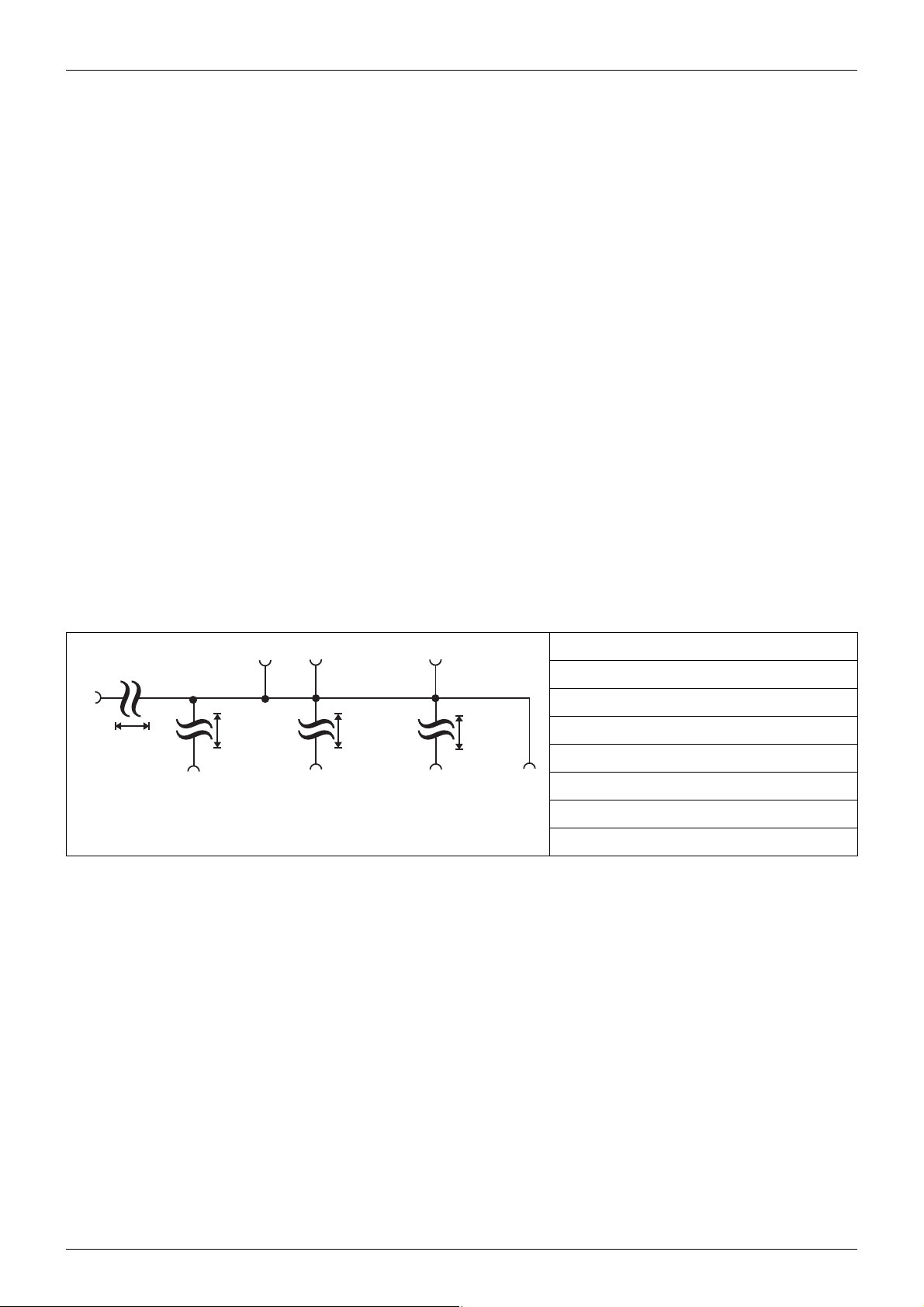
2.4 Installation notes
• The device is not suitable for installation in explosive areas (Ex areas).
• The choice of cable material, the installation and the electrical connection of the device must
conform to the requirements of DIN VDE 0100 "Installation of low-voltage power circuits"
and/or the appropriate local/national regulations (e.g. based on IEC 60364).
• At maximum load, the cables must be heat resistant up to at least 80 °C.
• The electrical connection must only be carried out by qualified personnel.
• The device is intended to be installed in electrical cabinets or systems. It shall be operated by
mains protected with a branch circuitry overcurrent protection device not more than 20 Amps.
For servicing/repairing a Disconnecting Device shall be provided to disconnect all conductors.
• The load circuit must be fused for the maximum relay current, in order to prevent the output
relay contacts from becoming welded in the event of a short circuit occurring at that point.
• The electromagnetic compatibility (EMC) meets the standards and regulations cited in the
technical data.
• Run input, output and supply cables separately and not in parallel with one another.
• Sensor and interface cables should be shielded cables with twisted conductors. Do not run
cables close to current-carrying components or cables. Ground the shielding on one side.
• Do not connect other consumers to the power terminals of the device.
2.5 Electrical isolation
(1) Analog input
(2) Binary input
(3) Setup interface (USB)
(4) Voltage supply
(5) RS485 interface
(6) Analog output
(7) Relay outputs
(8) Logic outputs
10
2 Installation - Electrical Connection
13
14
76
12
11
10
9
8
N(L-)
5
L1(L+)
4
USB
N(L-)
L1(L+)
14
15
16
17
18
19
5
11
10
13
12
4
7
8
9
USB
N(L-)
L1(L+)
5
11
10
4
7
8
9
14
15
16
17
18
19
13
12
USB
2.6 Connection diagram
The terminal strips on the device rear are equipped with screw terminals. Please refer to the technical data for specifications concerning the conductor cross section.
LC100 LC200 LC300
TIP!
The USB interface (socket Mini-B, 5-pole) is labeled on the device with "SETUP“
and is located on the case top of the LC100 and on the case bottom of the LC200
and LC300. It is used for connection to a PC that is running the setup program.
11
2 Installation - Electrical Connection
+
-
U
+
-
x
I
x
+
-
xIx
U
,
-
+
U
+
-
x
RxD/TxD
+
-
AC/DC
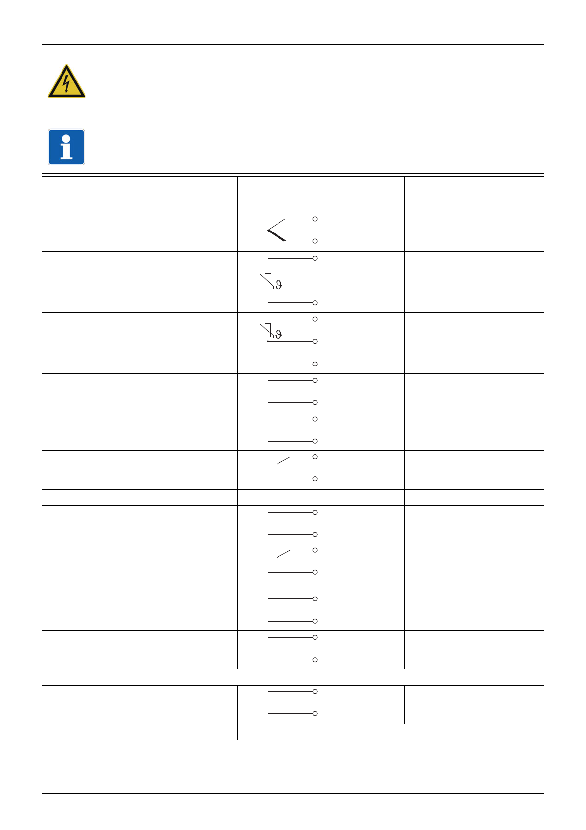
DANGER!
The electrical installation may carry voltage.
Risk of electrocution.
The electrical connection must only be performed by qualified personnel.
TIP!
Prior to starting the electrical connection, check that the device version complies
with the order code.
Connections Symbol LC100 LC200/LC300
Analog input
Thermocouple 9 10
811
RTD temperature probe, 2-wire 10 9
811
RTD temperature probe, 3-wire 10 9
910
811
Voltage
DC 0 to 10 V
Current
DC 0(4) to 20 mA
Binary input
for potential-free contact
Output:12312345
Analog output
DC 0 to 10 V, DC 0(4) to 20 mA
Relay output (N/O)
(max. 3 A at AC 230 V, resistive
load)
Logic output (DC 0/14 V) 13 7 12 14 16 18
RS485 interface 714
12 7
11 8
910
811
11 7
12 8
13 12
14 13
4136 412141618
5147 513151719
14 6 13151719
615
Output 1 as standard; Outputs 2 to 5 optional (options 1 to 4)
Voltage supply L1 (L+) L1 (L+)
N (L-) N (L-)
Setup interface USB socket, type Mini-B 5-pole
12

3 Operation - Configuration - Parameterization
(H)
(G)
(E)
(F)
(A)
(B) (C) (D)
t
w/x
t1
rASL
t2
SP1
t
w
SP2
SP1
w/x
rASL
x
t1
t2 t3 t4
t1
3.1 Operation
3.1.1 Display and operating elements
(A) Programming / one level deeper
(B) Value reduction / previous parameter
(C) Value increase / next parameter
(D) Function key / leave level
(E) Red 7-segment display (factory-set: Actual
value); 4-digit, configurable decimal place (automatic adjustment in the case of display overflow)
(F) Green 7-segment display (factory-set: Setpoint);
4-digit, configurable decimal place; also display
of level and parameter symbols
The software version is displayed on
the device when simultaneously pressing keys (A) and (C).
(G) LED 1 to 3(5): Switching position of binary output
(LED is lit = output active)
(H) LED ramp function or firing curve
3.1.2 Self-optimization, setpoint and manual mode
On the basis of the Normal display, the following Functions are available:
Start of self-optimization: Simultane-
ously press keys (B) and (C) (> 2 s)
Abort of self-optimization: Simulta-
neously press keys (B) and (C)
Change setpoint using keys (B) and
(C)
Function key (D) (> 2 s) is used to
Change-over to manual mode and to
exit the manual mode
"tUnE“ flashes in the lower display.
No parameters are changed by the abort.
The longer the key is kept pressed, the faster the set
point value changes. The value will be automatically
applied.
The output level (%) is displayed in the lower display
and can be changed with the keys (B) and (C).
(The controller automatically changes to manual mode
in the event of overrange/underrange and probe
break.)
3.1.3 Ramp function/firing curve
Ramp function (start after mains ON or with
the binary function)
t1:
Start (actual
value)
t2:
Setpoint setting
was reached
LED (H): Is lit with the ramp function active LED (H): Flashes in phase 1 (t1 to t2), is lit in
Firing curve (start with the binary function or
using the function key)
t1:
Start
t2:
SP1 -> SP2
(automatically)
t3:
Timer start
t4:
Timer end
phases 2 and 3 (t2 to t4)
OFF (F): Firing curve not active
13

3 Operation - Configuration - Parameterization
ConF
> 2s
PArA
(11)
OPr
(1) (3)
(4)
(2)
(5)
(6)
(14)
(12)
(10)
(13)
3.1.4 Level concept
The parameters for device setting are organized at different levels.
(1) Changeover from normal display to the levels
(2) Changeover between levels
(3) Changeover to the operator level (setpoints,
process values, timer value and time)
(4) Changeover to the parameter level (controller
parameters)
(5) Changeover to configuration level (analog input,
controller, ramp function, limit value monitoring,
timer, outputs, binary functions, display and
operation, interface)
(6) Return to the normal display
(10) Navigation principle:
If no key is pressed for 180 s (factorysetting), the device will return to its
(11) - one level deeper
(12) - next parameter / increase value
normal display. This time period can
be configured.
(13) - previous parameter / reduce value
(14) - one level back
The various levels are also accessible in manual mode.
Level inhibit (factory-setting: all levels are free):
Code Operator
level
0 free free free
1 free free inhibited
2 free inhibited inhibited
3 inhibited inhibited inhibited
Parameter
level
Configuration level
1. Simultaneously press (A) and (B) (> 5 s)
2. Press (A) (display flashes)
3. Enter code using (B) or (C)
4. Use (D) to return to the normal display
(or automatically after 180 s)
(key designation in brackets;
see chapter 3.1.1)
3.1.5 Operator level (OPr)
Depending on the configuration, the following parameters are available:
Symbol Description Symbol Description
SP1 Setpoint 1 (can be edited) rASL Ramp rate (for firing curve; can be
edited)
SP2 Setpoint 2 (can be edited) SPr Current ramp setpoint (for ramp
function or firing curve)
t1 Timer value (if timer or firing curve
tL Timer run time (if timer or firing
tr Residual timer run time (if timer or
14
are inactive; can be edited)
curve are active)
firing curve are active)
InP1 Measured value at analog input
y Output level

3 Operation - Configuration - Parameterization
3.2 Configuration (ConF)
TIP!
The device will map out parameters unless the equipment level permits the function
assigned to the parameter. Factory settings appear in bold in the following table.
Analog selector
With some parameters in the configuration level, the user can choose from a series of analog
values. The following list contains all available signals.
Value Description Value Description
0 Switched off 7 Setpoint 2
1 Analog input 8 Output level display
(-100 % to +100 %)
2 Actual value 9 Controller output 1 (e.g. heating,
output level 0 to +100 %)
3 Current setpoint 10 Controller output 2 (e.g. cooling,
output level 0 to -100 %)
4 Ramp end value 11 Timer run time (time unit of the
timer)
5 (reserved) 12 Timer residual time (time unit of the
timer)
6Setpoint 1
3.2.1 Analog input (InP)
ConF
-> InP ->
Parameters Value Description Value Description
Probe type
SEnS
0 Pt100 3-wire 9 NiCr-Ni K
1 Pt1000 3-wire 10 Pt10Rh-Pt S
2 Pt100 2-wire 11 Pt13Rh-Pt R
3 Pt1000 2-wire 12 NiCrSi-NiSi N
4 KTY 2 wire 13 NiCr-CuNi E
RTD temperature probe: Thermocouples:
5 Cu-50 3-wire Standard signals:
Thermocouples: 14 0 to 20 mA
6 Cu-CuNi T 15 4 to 20 mA
7 Fe-CuNi J 16 0 to 10 V
8 Fe-CuNi L
When selecting "0 to 10 V“, binary input
bin1 is inactive.
15

3 Operation - Configuration - Parameterization
Parameters Value Description
Measured value
offset
OFFS
Display start
SCL
Display end
SCH
Filter time constantdF0.0 ...
Temperature unit
Unit
(Setup program: Adjustable resistance of the KTY at 25 °C.)
-1999 ...
0 ...
+9999
-1999 ...
0 ...
+9999
-1999 ...
100 ...
+9999
0.6 ...
100.0 (s)
1 deg. Celsius
2 deg. Fahrenheit
The measured value is corrected through this value (offset),
prior to being used as a controller input value and in the analog
selector.
On transducers with standard signal, a display value is
assigned to the physical signal.
Example: 0 to 20 mA = 0 to 1500 °C
Adaptation of the digital input filter (0 = Filter OFF)
3.2.2 Controller (Cntr)
The actual value is provided for the controller by the analog input.
ConF -> Cntr ->
Parameters Value Description
Controller type
CtyP
Action
CACt
Output value,
manual mode
HAnd
Output level at
Out-of-Range
rOut
Setpoint limit start
SPL
Setpoint limit end
SPH
1 2-state controller
2 3-state controller
3 Continuous controller
0 Direct: (The output level of the controller is > 0 when the actual
value exceeds the setpoint, e.g. cooling).
1 Inverse: (The output level of the controller is > 0 when the
actual value is smaller than the setpoint, e.g. heating.)
-100 ...
0 ...
+101
-100 ...
0 ...
+100
-1999 ...
+9999
-1999 ...
+9999
Output level after switching to manual mode
101 = last output value
Output level in the event of overrange or underrange
The setpoint limitation prevents the entry of values exceeding
the default range.
The setpoint limits are not effective when entering setpoints
via the interface. The correction value is limited for external
setpoints with offset.
(Setup program: Manual mode and self-optimization can be inhibited.)
16

3 Operation - Configuration - Parameterization
3.2.3 Ramp function/firing curve (rAFC)
The device can be operated as a fixed value controller with and without ramp function. In addition, a firing curve is supported.
ConF -> rAFC ->
Parameters Value Description
Function
FnCt
Ramp rate
rASL
(Setup program: For the firing curve, timer value, time unit and setpoint can also be set here.)
0 Ramp function/firing curve switched off
1 Ramp function Kelvin/Minute
2 Ramp function Kelvin/Hour
3 Ramp function Kelvin/Day
4 Firing curve Kelvin/Minute
5 Firing curve Kelvin/Hour
6 Firing curve Kelvin/Day
0 ...
999
Value of the ramp rate (only for function = 1 to 6)
3.2.4 Limit value monitoring (Li1, Li2)
The device is equipped with two functions for limit value monitoring (Li 1, Li 2) each with eight
different alarm functions (AF1 to AF8). The two output signals are available for binary functions.
ConF -> LiI , Li2 ->
Parameters Value Description
Alarm function
FnCt
Limit value
AL, AL2
Switching
differential
HySt
0 Limit value monitoring switched off
1 AF1: Limit value above and below the setpoint (monitoring
range); symmetric or asymmetric
2 AF2: As AF1, output signal inverted
3 AF3: Limit value below the setpoint
4 AF4: As AF3, output signal inverted
5 AF5: Limit value above the setpoint
6 AF6: As AF5, output signal inverted
7 AF7: Fixed limit value (setpoint independent)
8 AF8: As AF7, output signal inverted
-1999 ...
0 ...
+9999
0 ... 1 ...
9999
Limit value to be monitored
For asymmetrical limit value: AL is below the setpoint, AL2 is
above the setpoint.
Limit value range for AF1 and AF2: 0 to 9999
Switching differential in respect to the limit value
17

3 Operation - Configuration - Parameterization
Parameters Value Description
Response at
Out-of-Range /
symmetry of limit
value
ACrA
Switch-on
delay
0 Off / symmetric (only AL is active)
1 On / symmetric (only AL is active)
2 Off / asymmetric (AL and AL2 are active)
3 On / asymmetric (AL and AL2 are active)
Switching state in the event of overrange or underrange ("Out-
of-Range“) / symmetry of alarm functions AF1, AF2
0 ... 9999 Switch-on delay of the output signal (in seconds)
tOn
Actual value
AFPr
Setpoint value
AFSP
2 Signal to be monitored; 2 = actual value
"Analog selector", page 15
3 Setpoint for limit value monitoring (reference signal for AF1 to
AF6); 3 = current setpoint
"Analog selector", page 15
3.2.5 Timer (tFCt)
The timer provides an output signal available for the binary functions. This signal can be used,
e.g. to realize a time-limited control or a time-dependent setpoint changeover.
The timer value is not saved during a mains failure. After the mains connection is restored, the
timer remains inactive.
ConF -> tFCt ->
Parameters Value Description
Function
FnCt
Start condition
Strt
Time unit
Unit
Timer value
t1
0 Timer switched off
1 Timer signal is "high“ while the timer is running
2 Timer signal is "low“ while the timer is running
0 Manual start via function key or binary signal (no restart after
mains failure)
1 Automatic start after mains ON (restart after mains failure);
manual start is also possible
0 mm:ss
1 hh:mm
2 hhh.h
00.00.
...
999.9.
Timer run time (in the time unit set)
Tolerance band
toLt
18
0 ...
9999
Tolerance band for timer start
The timer only starts once the actual value has reached the
tolerance band.
0 = Start without tolerance band

3 Operation - Configuration - Parameterization
3.2.6 Outputs (OutL, OutA)
The configuration of the device outputs is subdivided in binary outputs (OutL) and analog output
(OutA). The switching states of binary outputs 1 to 3 (5) are displayed by LEDs K1 to K3 (K5) (LED
is lit = output active).
Binary outputs
The device is equipped with a relay output (N/O, output 1) as standard and can be optionally
equipped with two (four) additional binary outputs (relay or logic output; outputs 2 to 5).
ConF -> OutL ->
Parameters Value Description
Output 1 ... 5
Out1
Out2
Out3
Out4
Out5
(Setup program: The output signal can be inverted.)
Analog output
The device can be optionally equipped with an analog output (output 2).
0 Output not active (factory setting for Out2 ... Out5)
1 Controller output 1 (factory setting for Out1)
2 Controller output 2
3 Binary input
4 Limit value monitoring 1
5 Limit value monitoring 2
6 Timer signal
ConF -> OutA ->
Parameters Value Description
Function
FnCt
Type of signal
9 Function of the output; 9 = Controller output 1
"Analog selector", page 15
Physical output signal
SiGn
Value at
Out-of-Range
rOut
Zero point
0Pnt
End value
End
0 0 ... 20 mA
1 4 ... 20 mA
2 0 ... 10 V
0 ... 101 Signal (in percent) at overrange or underrange
101 = last output signal
-1999 ...
0 ...
+9999
-1999 ...
100 ...
+9999
Value range of the output variable for the physical output sig-
nal
19

3 Operation - Configuration - Parameterization
3.2.7 Binary functions (binF)
The binary signals of the binary output, the limit value monitoring and the timer can be used to
trigger different functions.
The binary functions for start and abort react to the rising flank of the triggering signal, all other
binary functions are state-dependent controlled and active with "High".
ConF -> binF ->
Parameters Value Description
Binary input
bin1
Limit value monitoring 1 and 2
LiI, Li2
Timer signal
tF1
0 Signal without function
1 Start self-optimization
2 Abort self-optimization
3 Change to manual mode
4 Switch off controller (controller outputs inactive)
5 Switch on controller
6 Inhibit manual mode
7 Stop ramp/firing curve
8 Abort ramp/firing curve
9 Restart ramp, start/abort firing curve
10 Switch over from setpoint 1 to setpoint 2
11 Lock keypad
12 Inhibit parameter and configuration level,
inhibit self-optimization start
13 Switch off the display
14 Start timer
15 Abort timer
16 Stop timer
17 Start/abort timer
3.2.8 Display and operation (diSP)
Both displays and the function key can be individually adapted to the respective requirements.
ConF -> diSP ->
Parameters Value Description
Upper display
diSU
Lower display
diSL
2 Display value for the upper display; 2 = Actual value
"Analog selector", page 15
3 Display value for the lower display; 3 = current set point
value
"Analog selector", page 15
20

3 Operation - Configuration - Parameterization
Parameters Value Description
Display change
when timer is
started
diSt
Time-out
tout
Decimal place
dECP
Function key, press
briefly (< 2 s)
tAS
(Setup program: The function of pressing the function key longer (> 2 s) can also be configured.)
0 No display change
1 Residual timer time
2 Timer run time
0 ...
180 ...
255
0 No decimal place
1 One decimal place
2 Two decimal places
0 No function
1 Start timer/firing curve
2 Abort timer/firing curve
3 Stop/continue timer/firing curve run
4 Start/abort timer/firing curve
5 Timer display (timer run time or residual timer time)
Time appears in the bottom display once the timer is started
Time period in seconds, after which the device automatically
returns to its normal display (if no key is pressed).
0 = Function switched off
3.2.9 Interface (IntF)
An optional RS485 interface can be used to integrate the device in a data network. When the
communication takes place via the setup interface, the RS485 interface is inactive.
ConF -> IntF ->
Parameters Value Description
Baud rate
bdrt
Device address
Adr
For further information about the RS485 interface, the Modbus protocol and the communication
with other devices, please refer to the interface description B 702030.2.0 available as a PDF
document under www.jumo.net.
0 9600 baud
1 19200 baud
0 ...
1 ...
254
Address in data network
21

3 Operation - Configuration - Parameterization
3.3 Parameterization (PArA)
Enter the controller parameters here.
PArA ->
Parameters Value Description
Proportional band
PB1, PB2
Derivative time
1
dt
Reset time
rt
Cycle time
Cy1, Cy2
Contact spacing
1
db
0 ...
9999
0 ...
80 ...
9999 (s)
0 ...
350 ...
9999 (s)
0.0 ...
20.0 ...
999.9 (s)
0.0 ...
999.9
Range of the proportional band
The larger the proportional band the lower the controller ampli-
fication.
The controller structure is not effective with Pb = 0 (behavior
identical to limit value monitoring). For the continuous control-
ler, ensure that Pb is > 0.
Influences the differential portion of the controller output signal
The larger the derivative time the higher the effectiveness of
the D portion.
0 = derivative time switched off (no D portion)
Influences the integral portion of the controller output signal
The larger the reset time the lower the effectiveness of the I
portion.
0 = reset time switched off (no I portion)
When using a switched output, the cycle time should be cho-
sen so that the energy flow to the process is as continuous as
is practicable without overloading the switching elements.
Spacing between the two control contacts of a 3-state control-
ler
Hysteresis
HyS1, HyS2
Working point
1
y0
Output level limiting
y1, y2
1
Only available for 3-state controllers (controller output 2)
The display of parameters depends on the controller type. For some parameters, the decimal
place depends on the device setting.
Factory settings appear in bold.
0.0 ...
1.0 ...
999.9
-100 ...
0 ...
+100
0 ...
100 (%)
-100 ...
+100 (%)
Hysteresis for a switching controller with proportional range
Pb = 0 (behavior identical to that for limit value monitoring)
The output level for P and PD controllers (if x = w then y = y0)
y1: Maximum output level limitation
y2: Minimum output level limitation
(only effective when Pb > 0)
22

4 Supplement
45
+0.6
45
+0.6
(1)
(2)
4.1 Additional information about installation
TIP!
The information given in this chapter is exclusively contained in this operating
manual provided as PDF document. It supplements the information contained in the
previous chapters of this operating manual as well as in the brief instructions added
to every device as a print out.
The ambient conditions at the installation site must meet the requirements specified in the technical data.
The device is not suitable for installation in explosive areas (Ex areas).
4.1.1 Device representation including dimensions
LC100
(1) Setup interface (USB)
on the device top
(2) Panel cut-out
23

4 Supplement
92
+0.8
45
+0.8
(1)
(2)
LC200
(1) Setup interface (USB)
on the device bottom
24
(2) Panel cut-out

LC300
92
+0.8
92
+0.8
(1)
(2)
4 Supplement
(1) Setup interface (USB)
(2) Panel cut-out
on the device bottom
Minimum spacing of panel cut-outs
Type without USB cable with USB cable
horizontal vertical horizontal vertical
LC100 11 mm 30 mm 11 mm 65 mm
LC200 22 mm 30 mm 22 mm 65 mm
LC300 22 mm 30 mm 22 mm 65 mm
4.1.2 Cleaning the device front
The device front panel can be cleaned with commercial cleaning and rinsing agents. It has a
limited resistance to organic solvents (such as ethyl alcohol, turpentine substitute, P1, xylol and
similar). Do not use high-pressure cleaning equipment.
25

4 Supplement
(1)
(2)
(3)
(C)
(B)
(C)
(B)
(A)
(1)
(2)
(3)
(C)
(B)
(C)
(B)
(A)
4.2 Additional information about the device functions
TIP!
The information given in this chapter is exclusively contained in this operating manual provided as a PDF document. It supplements the information contained in the
previous chapters of this operating manual as well as in the brief instructions added
to every device as a print out.
4.2.1 Entries and operator prompting
Value entry
When entries are made within the levels, the parameter symbol appears in the lower display.
(1) Select parameter (lower
display - green)
(2) Change value (upper
display - red)
(3) Parameter flashes
Time entry
A decimal place is mapped in the centre and on the right to display times. The time unit can be
configured.
(1) Select parameter (lower
display - green)
(2) Change value (upper
display - red)
(3) Parameter flashes
Procedure
1. Select parameter with key (B) or (C)
2. Change-over to the input mode with key (A): The lower display flashes.
3. Change value with key (B) or (C)
The longer the key is kept pressed, the faster the value changes.
4. Apply setting with key (A) (value is automatically applied after 2 s) - or cancel entry using
key (D) (value will not be applied)
TIP!
When pressing function key (D) for more than 2 seconds, the device will return to
the normal display
26

4 Supplement
4.2.2 Analog input
Measured value offset
A measured value correction (offset) can be carried out to correct system specific deviations. The
offset value is added to the measured value with the correct prefix (the measured value is reduced by entering a negative offset value).
CAUTION!
Measured value offset: The controller uses the corrected value for calculation (= displayed value). When the measured value has been offset, the corrected value does
no longer correspond to the value measured at the measuring point.
Incorrect use can cause inadmissible values of the control variable.
Only carry out a measured value offset within the admissible range.
Filter time constant
The filter time constant serves to adapt the digital input filter (filter of second priority). At a step
change of the input signal, approx. 26 % of the change is detected after the elapse of a time period corresponding to the filter time constant dF (2 x dF: approx. 59 %; 5 x dF: approx. 96 %).
A high filter time constant means:
• High damping of interference signals
• Slow reaction of the actual value display to actual value changes
• Low limit frequency
4.2.3 Analog output
Zero point and end value
The factory setting corresponds to an output level of 0 ... 100 % for the continuous controller (controller output 1): zero point = 0, end value = 100
If the analog output is used as controller output 2 for the 3-state controller (e.g. for cooling), the
following setting is required: zero point = 0, end value = -100
If, for example, the actual value is to be put out, which can be within the range of 150 °C to
500 °C, select the limits so that they correspond to the minimum and maximum temperature:
zero point = 150, end value = 500
27

4 Supplement
t
w/x
t1
rASL
t2
SP1
t
w
SP2
SP1
w/x
rASL
x
t1
t2 t3 t4
t1
4.2.4 Ramp function and firing curve
Ramp function
This function allows the continuous change of the setpoint up to the ramp end value (setpoint
setting SP1 or SP2). Depending on the actual value at ramp start, this results in a rising or falling
ramp with identical gradient (adjustable ramp ratio rASL).
The ramp starts after mains ON (or through the binary
function) at time t1 and starts at the actual value. The setpoint
reached at time t2.
When switching over or changing the setpoint, the new
setpoint is also moved to at ramp ratio rASL.
SP1 (or SP2) is moved to at ramp ratio rASL and is
LED "Ramp“ (H): Is lit with active
ramp function (until it is cancelled)
TIP!
The ramp function is interrupted in the event of a probe break, probe short-circuit,
overrange/underrange or changeover to manual mode. Once the event is remedied
(or after switching to automatic mode), the ramp function continues at the current
actual value.
After the power supply is restored, the ramp function starts at the current actual
value.
Firing curve
For use in small kilns, a firing curve can be saved for controlled start-up and time-dependent
firing.
With this function, the parameters setpoint 1 (SP1), setpoint 2 (SP2), ramp rate (rASL) and timer
value (
t1) are automatically linked to each other.
The ramp can be stopped or aborted using the binary
function. When aborted, the setpoint setting
is used to control.
Phase 1 (t1 to t2): The firing curve is started by using the
function key or with the binary function (time t1) and
starts at the actual value. The setpoint
ramp ratio
rASL.
SP1 is moved to at
SP1 (or SP2)
LED "Ramp“ (H):
Flashes in phase 1,
is lit in phase 2 and 3
28
Phase 2 (t2 to t3): Once the current ramp value has
reached the setpoint SP1 (t2), the device automatically
switches over to setpoint
approaches the new setpoint (the ramp ratio is of no
importance).
Phase 3 (t3 to t4): The timer starts when the actual value
has reached the setpoint
the set time (timer value
(t4), the controller switches off (setpoint display = 0).
SP2 (w). The actual value (x)
SP2 (t3) and keeps running for
t1). Once the timer has elapsed

TIP!
S
SP1
w/x
t
t1
w/x
t
SP1
t1
S
tOLt
(A) (B)
SP2
SP1
w/x
t
SP2
SP1
w/x
t
SP2
w/x
t
P
S
t1
t1
t1
(C)
(A) (B)
tOLt
SP1
S
PP
The firing curve can only be started when the actual value is smaller than setpoint 1.
The firing curve is aborted in the event of a probe break, probe short-circuit, overrange/underrange or change-over to manual mode (controller switched off).
After the power supply is restored, the firing curve is not active (controller switched
off).
When the firing curve is not active, OFF appears in the lower display.
4.2.5 Timers
The following functions can be realized when using the binary functions.
Time-limited control
The control is switched off once the timer has elapsed (output level 0 %).
(A) Without tolerance band
(B) With tolerance band
SP1 Setpoint 1
4 Supplement
Time-dependent setpoint changeover
After the timer is started, the controller is automatically set to setpoint SP2. Once the timer has
elapsed, the controller automatically switches to SP1.
tOLt Tolerance band
t1 Timer value
S Start (manual)
(A) Manual start
(B) Automatic start after
power ON
(C) Manual start with
tolerance band
SP1 Setpoint 1
SP2 Setpoint 2
tOLt Tolerance band
t1 Timer value
PPower ON
S Start (manual)
29

4 Supplement
w
1
AL
x
HySt
0
AL
AL
HySt
0
1
w
x
AL
w
1
AL
x
HySt
0
AL2
AL
HySt
0
1
w
x
AL2
w
1
AL
x
HySt
0
AL
HySt
1
0
w
x
AL
w
1
x
HySt
0
AL
HySt
1
0
w
x
AL
1
x
HySt
0
AL
HySt
1
0
x
4.2.6 Limit value monitoring
The following representations show the function of limit value (AL, AL2) for the various alarm
functions AF1 to AF8. The hysteresis (HySt) is always symmetrical in relation to the limit value.
Limit value referring to setpoint w
AF1 symmetric AF2 symmetric
AF1 asymmetric AF2 asymmetric
AF3 AF4
AF5 AF6
Fixed limit value
AF7 AF8
4.2.7 Self-optimization (TUNE)
Self-optimization operates according to the oscillation method and determines the optimum parameters for a PID or PI controller.
The following parameters are optimized depending on the controller type configured (2-state, 3state, continuous controller) and the controller structure (parameterization):
Proportional band (Pb1, Pb2), derivative time (dt), reset time (rt), cycle time (Cy1, Cy2), filter time
constant (dF; parameter of the analog input).
30

4 Supplement
t
x
w
T
S
w
x
T
t
S
Depending on the value of the control deviation, the controller selects between two self-optimization methods:
Self-optimization in the startup-phase
Self-optimization at the
setpoint
wSetpoint
S Switching curve
T Start time of self-optimi-
zation
Prerequisites
The following prerequisites must be fulfilled to be able to start self-optimization:
• Self-optimization start is not inhibited by the binary function (binF)
• Controller is in the automatic mode, not in the manual mode
• No parameter level inhibit active via setup program
• Ensure that keys (B) and (C) are not pressed one after the other. They must always be pressed
simultaneously.
Furthermore, the following points should be taken into consideration, checked and, if necessary,
adjusted, prior to starting self-optimization:
• Is the suitable controller type configured?
• Check and/or adjust the control action of the controller
• Is it possible to sufficiently influence the actual value in the manual mode?
• Only for continuous controller: The function of the output (OutP -> OutA) must be configured
as controller output 1 and scaled to 0 ... 100 %. This means:
Function (FnCt) = Controller output 1 (9)
Zero point (0Pnt) = 0
End value (End) = 100
Depending on the controller type and parameter setting, the controller structures and specific parameters are optimized:
Controller type Parameter setting Optimized cont-
Optimized parameters
roller structure
2-state controller rt > 0; dt = 0; Pb1 = any PI Pb1, rt, Cy1, dF
all other settings PID Pb1, dt, rt, Cy1, dF
3-state controller rt > 0; dt = 0;
PI Pb1, Pb2, rt, Cy1, Cy2, dF
Pb1 = Pb2 = any
all other settings PID Pb1, Pb2, dt, rt, Cy1, Cy2,
dF
Continuous
controller
rt > 0; dt = 0; Pb1 = any PI Pb1, rt, dF
all other settings PID Pb1, dt, rt, dF
31

4 Supplement
Start of self-optimization
Simultaneously press keys (B) and (C) (> 2 s):
"tUnE“ flashes in the lower display.
Self-optimization is completed when the display automatically changes to the normal display.
The duration of self-optimization depends on the control process.
Abort of self-optimization
Simultaneously press keys (B) and (C)
No parameters are changed by the abort.
32

4.3 Error messages
Display Cause Fault remedy
4 Supplement
-1999
(flashing!)
9999
(flashing!)
PErr Firing curve start is impos-
Overrange / underrange covers the following events:
• Probe break/short-circuit
• Measured value outside the probe measuring range
• Display overflow
No keyboard operations are possible during device initialization (all displays are switched on, the
upper 7-segment display flashes).
Underrange of the displayed value.
Overrange of the displayed
value.
sible because
the actual value is ≥ than
the setpoint 1
Is the medium being measured within the
range (too hot? too cold?)
Check probe for break and short-circuit.
Check the probe connection and the termi-
nals.
Check cable.
Check that the connected probe complies
with the configured probe type
The firing curve can be started when
the actual value is < than the setpoint 1
33

4 Supplement
4.4 Technical Data
Thermocouple input
Designation Standard Measuring range
Fe-CuNi „L“
Fe-CuNi „J“
Cu-CuNi „T“
NiCr-Ni „K“
NiCr-CuNi „E“
NiCrSi-NiSi „N“
Pt10Rh-Pt „S“
Pt13Rh-Pt „R“
EN 60584
EN 60584
EN 60584
EN 60584
EN 60584
EN 60584
EN 60584
-150 to +900 °C
-200 to +1200 °C
-200 to +400 °C
-200 to +1372 °C
-200 to +1000 °C
-100 to +1300 °C
-40 to +1768 °C
-40 to +1768 °C
Cold junction: KTY internal
a
The specifications refer to an ambient temperature of 20°C.
b
Including measuring accuracy at the internal cold junction.
The accuracy values refer to the measuring range.
RTD temperature probe input
Designation,
Measuring range Measuring
connection type
a
Measuring
accuracy
≤ 0.4 %
≤ 0.4 %
≤ 0.4 %
≤ 0.4 %
≤ 0.4 %
≤ 0.4 %
≤ 0.4 %
≤ 0.4 %
accuracy
b
temperature
influence
≤ 100 ppm/ K
≤ 100 ppm/ K
≤ 100 ppm/ K
≤ 100 ppm/ K
≤ 100 ppm/ K
≤ 100 ppm/ K
≤ 100 ppm/ K
≤ 100 ppm/ K
Ambient
Ambient
a
temperature
influence
Pt100 DIN EN 60751
2-wire connection
3-wire connection
Pt1000 DIN EN 60751
2-wire connection
3-wire connection
KTY, R25 = 1000 Ω
2-wire connection
KTY, R25 = 2000 Ω
2-wire connection
Cu-50
3-wire connection
-200 to +650 °C
-200 to +650 °C
-50 to +150 °C
-50 to +80 °C
-50 to +200 °C
≤ 50 ppm/K
≤ 0.4 %
≤ 0.4 %
≤ 50 ppm/ K
≤ 0.4 %
≤ 0.4 %
≤ 50 ppm/ K
≤ 1.0 %
≤ 50 ppm/ K
≤ 1.0 %
≤ 50 ppm/ K
≤ 1.0 %
Probe wire resistance: max. 30 Ω per wire with 3-wire circuit
Measured current: Pt100 approx. 1 mA; Pt1000 and KTY approx. 100 μA
Lead compensation: Not required for 3-wire circuit. For a 2-wire circuit, the lead resistance can
be compensated by correcting the actual value.
a
The accuracy values refer to the measuring range.
34

Input for standard signals
4 Supplement
Measuring range Measuring
a
Voltage 0 to 10 V
accuracy
≤ 0.4 % ≤ 150 ppm/K
Ambient
temperature influence
Input resistance > 650 kΩ
Current 0(4) to 20 mA
≤ 0.4 % ≤ 100 ppm/K
voltage drop > 2.2 V
a
The accuracy values refer to the maximum measuring range.
Binary input
Input for potential-free contact open = inactive;
closed = active
Measuring circuit monitoring
In the event of a fault, the outputs adopt a defined (configurable) status.
Measuring probe Overrange /
underrange
Probe /
cable short circuit
Probe /
cable break
Thermocouple • - •
RTD
•••
temperature probe
Voltage 0 to 10 V - - Current 4 to 20 mA • • •
Current 0 to 20 mA - - -
• = detected - = not detected
Outputs
Relay (N/O)
Contact rating
Contact life
max. 3 A at 230 V AC resistive load
150,000 operations at nominal load
350,000 operations at 1 A
310,000 operations at 1 A and cos ϕ > 0.7
Logic output 0/14V / 20 mA max.
Voltage (option)
Output signal
Load resistance
Accuracy
Current (option)
Output signals
Load resistance
Accuracy
0 to 10 V
> 600 Ω
< 0.5 %
0 to 20 mA / 4 to 20 mA
< 450 Ω
< 0.5 %
35

4 Supplement
Controller
Controller type 2-state controller, 3-state controller, continuous controller
Controller structures P/PI/PD/PID
Sampling time 250 ms
A/D converter 16 bit resolution
Timers
Accuracy 0.8 % ± 10 ppm/K ± 250 ms
Electrical data
Voltage supply (switch
mode PSU)
Electrical
safety
Power consumption max. 14 VA
Electrical connection on the rear via screw terminals; with core-end ferrule of a pipe
Conductor cross section fine-strand 0.25 to 1.5 mm
Tightening torque 0.5 Nm
Electromagnetic
compatibility
Interference emission Class A - Only for industrial use Interference immunity Industrial requirements
Setup interface USB socket, type Mini-B 5-pole
Requirements for core-end ferrules and cable lugs
Core-end ferrule pipe shape, without plastic sheath as per DIN 46228 part 1,
Cable lug open crimp cable lug, dimensionally adapted to DIN 46237 for
Pin cable lug as per DIN 46231
With UL applications use of the cable lugs or ferrules acc. to UL 486A-B (UL listed or
AC 110 to 240 V +10/-15 %, 48 to 63 Hz
AC/DC 20 to 30 V, 48 to 63 Hz
as per DIN EN 61010, part 1
overvoltage category III, pollution degree 2
shape, ope-n cable lug or pin cable lug
2
as per DIN EN 61326-1
with plastic sheath as per DIN 46228 part 4
closed crimp cable lugs
recognized)
Case
Case type plastic case for panel mounting as per IEC 61554 (indoor use)
Dimensions (front) LC100: 48 mm x 48 mm; LC200: 48 mm x 96 mm (portrait format);
LC300: 96 mm x 96 mm
Panel cut-out LC100: 45 mm x 45 mm; LC200: 45 mm x 92 mm;
LC300: 92 mm x 92 mm
Minimum spacing
horizontal / vertical
Depth behind panel LC100: max. 95 mm; LC200/LC300: max. 80 mm
Ambient / storage
temperature range
Ambient conditions rel. humidity < 90% annual average, without condensation
36
LC100: 11 mm / 30 mm (65 mm with USB cable);
LC200/LC300: 22 mm / 30 mm (65 mm with USB cable)
-5 to +55 °C / -40 to +70 °C

4 Supplement
Site altitude up to 2000 m above sea level
Operating position any
Protection type as per DIN EN 60529, at the front IP 65, at the rear IP 20
Weight (fully equipped) LC100: approx. 150 g; LC200: approx. 200 g;
LC300: approx. 300 g
Interface
Interface type RS485
Protocol Modbus RTU
Baud rate 9600, 19200
Data format 8 data bits, no parity bit, 1 stop bit
Device address 0 to 254
No. of subscribers max. 32
7-segment displays
Digit height
LC100, LC200 upper display: 10 mm; lower display: 7 mm
LC300 upper display: 20 mm; lower display: 13 mm
Color upper display: red; lower display: green
Places 4 (including decimal places)
Decimal places 0, 1, 2 (configurable)
Display range -1999 to 9999
Approvals/approval marks
Approval marks Inspection
authority
c UL us Underwriters
Laboratories
Certificate / Inspection number
E201387 UL 61010-1,
Inspection/test
basis
CAN/CSA C22.2
No. 61010-1
Valid for
all versions
37

4 Supplement
38


JUMO GmbH & Co. KG JUMO Instrument Co. Ltd. JUMO Process Control, Inc.
Street address:
Moritz-Juchheim-Straße 1
36039 Fulda, Germany
Delivery address:
Mackenrodtstraße 14
36039 Fulda, Germany
Postal address:
36035 Fulda, Germany
Phone: +49 661 6003-0
Fax: +49 661 6003-607
E-mail: mail@jumo.net
Internet: www.jumo.net
JUMO House
Temple Bank, Riverway
Harlow - Essex CM20 2DY, UK
Phone: +44 1279 63 55 33
Fax: +44 1279 63 52 62
E-mail: sales@jumo.co.uk
Internet: www.jumo.co.uk
6733 Myers Road
East Syracuse, NY 13057, USA
Phone: 315-437-5866
1-800-554-5866
Fax: 315-437-5860
E-mail: info.us@jumo.net
Internet: www.jumousa.com
 Loading...