

Page 1
JUMO mTRON T
Measuring, Control, and Automation System
Operating panels
Operating Manual
70506500T90Z001K000
V2.00/EN/00672050
Page 2

Page 3

3
Contents
1 Introduction . . . . . . . . . . . . . . . . . . . . . . . . . . . . . . . . . . . . . . . . . . . . . . . . . . . . . .5
1.1 Available technical documentation . . . . . . . . . . . . . . . . . . . . . . . . . . . . . . . . . . . . . . . . . . . . . . . . 5
1.1.1 General information . . . . . . . . . . . . . . . . . . . . . . . . . . . . . . . . . . . . . . . . . . . . . . . . . . . . . . . . . . . . 5
1.1.2 Base units . . . . . . . . . . . . . . . . . . . . . . . . . . . . . . . . . . . . . . . . . . . . . . . . . . . . . . . . . . . . . . . . . . . 5
1.1.3 Input/output modules . . . . . . . . . . . . . . . . . . . . . . . . . . . . . . . . . . . . . . . . . . . . . . . . . . . . . . . . . . . 6
1.1.4 Special modules . . . . . . . . . . . . . . . . . . . . . . . . . . . . . . . . . . . . . . . . . . . . . . . . . . . . . . . . . . . . . . 6
1.1.5 Operating, visualization, recording . . . . . . . . . . . . . . . . . . . . . . . . . . . . . . . . . . . . . . . . . . . . . . . . 7
1.1.6 Power supply units . . . . . . . . . . . . . . . . . . . . . . . . . . . . . . . . . . . . . . . . . . . . . . . . . . . . . . . . . . . . 7
1.2 Safety information . . . . . . . . . . . . . . . . . . . . . . . . . . . . . . . . . . . . . . . . . . . . . . . . . . . . . . . . . . . . . 8
1.2.1 Warning symbols . . . . . . . . . . . . . . . . . . . . . . . . . . . . . . . . . . . . . . . . . . . . . . . . . . . . . . . . . . . . . . 8
1.2.2 Note signs . . . . . . . . . . . . . . . . . . . . . . . . . . . . . . . . . . . . . . . . . . . . . . . . . . . . . . . . . . . . . . . . . . . 8
1.2.3 Intended use . . . . . . . . . . . . . . . . . . . . . . . . . . . . . . . . . . . . . . . . . . . . . . . . . . . . . . . . . . . . . . . . . 9
1.2.4 Qualification of personnel . . . . . . . . . . . . . . . . . . . . . . . . . . . . . . . . . . . . . . . . . . . . . . . . . . . . . . . 9
1.3 Acceptance of goods, storage, and transport . . . . . . . . . . . . . . . . . . . . . . . . . . . . . . . . . . . . . . . . 9
1.3.1 Checking the delivery . . . . . . . . . . . . . . . . . . . . . . . . . . . . . . . . . . . . . . . . . . . . . . . . . . . . . . . . . . 9
1.3.2 Notes on storage and transport . . . . . . . . . . . . . . . . . . . . . . . . . . . . . . . . . . . . . . . . . . . . . . . . . . . 9
1.3.3 Returning goods . . . . . . . . . . . . . . . . . . . . . . . . . . . . . . . . . . . . . . . . . . . . . . . . . . . . . . . . . . . . . 10
1.3.4 Disposal . . . . . . . . . . . . . . . . . . . . . . . . . . . . . . . . . . . . . . . . . . . . . . . . . . . . . . . . . . . . . . . . . . . . 10
1.4 Device version . . . . . . . . . . . . . . . . . . . . . . . . . . . . . . . . . . . . . . . . . . . . . . . . . . . . . . . . . . . . . . . 11
1.4.1 Order details . . . . . . . . . . . . . . . . . . . . . . . . . . . . . . . . . . . . . . . . . . . . . . . . . . . . . . . . . . . . . . . . 11
1.4.2 Scope of delivery . . . . . . . . . . . . . . . . . . . . . . . . . . . . . . . . . . . . . . . . . . . . . . . . . . . . . . . . . . . . . 11
1.4.3 Accessories . . . . . . . . . . . . . . . . . . . . . . . . . . . . . . . . . . . . . . . . . . . . . . . . . . . . . . . . . . . . . . . . . 11
1.5 Brief description . . . . . . . . . . . . . . . . . . . . . . . . . . . . . . . . . . . . . . . . . . . . . . . . . . . . . . . . . . . . . . 12
1.6 System requirements . . . . . . . . . . . . . . . . . . . . . . . . . . . . . . . . . . . . . . . . . . . . . . . . . . . . . . . . . 12
1.7 Content of this document . . . . . . . . . . . . . . . . . . . . . . . . . . . . . . . . . . . . . . . . . . . . . . . . . . . . . . 12
2 Connection . . . . . . . . . . . . . . . . . . . . . . . . . . . . . . . . . . . . . . . . . . . . . . . . . . . . . .13
2.1 Installation notes . . . . . . . . . . . . . . . . . . . . . . . . . . . . . . . . . . . . . . . . . . . . . . . . . . . . . . . . . . . . . 13
2.2 LAN connection . . . . . . . . . . . . . . . . . . . . . . . . . . . . . . . . . . . . . . . . . . . . . . . . . . . . . . . . . . . . . . 15
3 Configuration . . . . . . . . . . . . . . . . . . . . . . . . . . . . . . . . . . . . . . . . . . . . . . . . . . . .17
3.1 General information . . . . . . . . . . . . . . . . . . . . . . . . . . . . . . . . . . . . . . . . . . . . . . . . . . . . . . . . . . . 17
3.2 Creating a PLC application . . . . . . . . . . . . . . . . . . . . . . . . . . . . . . . . . . . . . . . . . . . . . . . . . . . . . 18
3.2.1 Starting CODESYS . . . . . . . . . . . . . . . . . . . . . . . . . . . . . . . . . . . . . . . . . . . . . . . . . . . . . . . . . . . 18
3.2.2 Mapping a variable . . . . . . . . . . . . . . . . . . . . . . . . . . . . . . . . . . . . . . . . . . . . . . . . . . . . . . . . . . . 19
3.2.3 Select CODESYS feature set . . . . . . . . . . . . . . . . . . . . . . . . . . . . . . . . . . . . . . . . . . . . . . . . . . . 21
3.2.4 Install the repository package . . . . . . . . . . . . . . . . . . . . . . . . . . . . . . . . . . . . . . . . . . . . . . . . . . . 22
3.2.5 Insert the operating panel into the device tree . . . . . . . . . . . . . . . . . . . . . . . . . . . . . . . . . . . . . . 23
3.2.6 Transfer current firmware . . . . . . . . . . . . . . . . . . . . . . . . . . . . . . . . . . . . . . . . . . . . . . . . . . . . . . 25
3.2.7 Add data server and data source . . . . . . . . . . . . . . . . . . . . . . . . . . . . . . . . . . . . . . . . . . . . . . . . 26
3.2.8 Configure visualization . . . . . . . . . . . . . . . . . . . . . . . . . . . . . . . . . . . . . . . . . . . . . . . . . . . . . . . . 29
3.2.9 Close CODESYS project and save configuration . . . . . . . . . . . . . . . . . . . . . . . . . . . . . . . . . . . . 32
3.2.10 Start CODESYS for debugging . . . . . . . . . . . . . . . . . . . . . . . . . . . . . . . . . . . . . . . . . . . . . . . . . . 33
Page 4

Contents
4
3.2.11 Load configuration in operating panel . . . . . . . . . . . . . . . . . . . . . . . . . . . . . . . . . . . . . . . . . . . . . 34
3.2.12 Create a boot application . . . . . . . . . . . . . . . . . . . . . . . . . . . . . . . . . . . . . . . . . . . . . . . . . . . . . . 35
3.2.13 Close CODESYS project . . . . . . . . . . . . . . . . . . . . . . . . . . . . . . . . . . . . . . . . . . . . . . . . . . . . . . . 36
4 Technical data . . . . . . . . . . . . . . . . . . . . . . . . . . . . . . . . . . . . . . . . . . . . . . . . . . .37
4.1 Operating panel 350 (type 705065/0x-1...) . . . . . . . . . . . . . . . . . . . . . . . . . . . . . . . . . . . . . . . . . 37
4.2 Operating panel 570 (type 705065/0x-2...) . . . . . . . . . . . . . . . . . . . . . . . . . . . . . . . . . . . . . . . . . 39
4.3 Operating panel 1040 (type 705065/0x-5...) . . . . . . . . . . . . . . . . . . . . . . . . . . . . . . . . . . . . . . . . 41
Page 5
5
1 Introduction
1.1 Available technical documentation
The documents specified below are available for the measuring, control, and automation system (previous document number in parentheses).
1.1.1 General information
1.1.2 Base units
Product T ype of documentation No. Printed PDF file
Measuring,
control, and
automation system
Data sheet 70500000T10... - X
System manual
1
1
Accessory subject to charge
70500000T90...
(B 705000.0)
X-
Setup program manual 70500000T96...
(B 705000.6)
-X
System description
2
2
Includes an overview of the purpose and content of all documents
70500000T98...
(B 705000.8)
-X
Product T ype of documentation No. Printed PDF file
Central
processing unit
Data sheet 70500100T10... - X
Operating manual 70500100T90...
(B 705001.0)
-X
Modbus interface description 70500100T92...
(B 705001.2.0)
-X
PROFIBUS-DP interface description 70500103T92...
(B 705001.2.3)
-X
digiLine interface description 70500106T92... - X
Installation instructions 70500100T94...
(B 705001.4)
XX
CODESYS OPC server
operating manual
70500151T90...
(B 705001.5.1)
-X
Process engineering application
operating manual
70500152T90... - X
Operating manual
Thyristor power controller (type
70906x; integration in the measuring,
control, and automation system)
70500153T90... - X
Page 6
1 Introduction
6
1.1.3 Input/output modules
1.1.4 Special modules
Product T ype of documentation No. Printed PDF file
Multichannel
controller module
Data sheet 70501000T10... - X
Operating manual 70501000T90...
(B 705010.0)
-X
Installation instructions 70501000T94...
(B 705010.4)
XX
Relay module
4-channel
Data sheet 70501500T10... - X
Operating manual 70501500T90...
(B 705015.0)
-X
Installation instructions 70501500T94...
(B 705015.4)
XX
Analog
input module
4-channel
Data sheet 70502000T10... - X
Operating manual 70502000T90...
(B 705020.0)
-X
Installation instructions 70502000T94...
(B 705020.4)
XX
Analog
input module
8-channel
Data sheet 70502100T10... - X
Operating manual 70502100T90...
(B 705021.0)
-X
Installation instructions 70502100T94...
(B 705021.4)
XX
Analog
output module
4-channel
Data sheet 70502500T10... - X
Operating manual 70502500T90... - X
Installation instructions 70502500T94... X X
Digital input/
output module
12-channel
Data sheet 70503000T10... - X
Operating manual 70503000T90...
(B 705030.0)
-X
Installation instructions 70503000T94...
(B 705030.4)
XX
Product T ype of documentation No. Printed PDF file
Router module Data sheet 70504000T10... - X
Installation instructions 70504000T94...
(B 705040.4)
XX
Page 7
7
1 Introduction
1.1.5 Operating, visualization, recording
1.1.6 Power supply units
Product T ype of documentation No. Printed PDF file
Multifunction
panel 840
Data sheet 70506000T10... - X
Operating manual 70506000T90...
(B 705060.0)
-X
Modbus interface description 70506000T92...
(B 705060.2.0)
-X
Installation instructions 70506000T94...
(B 705060.4)
XX
Operating panels Data sheet 70506500T10... - X
Operating manual 70506500T90... - X
Product T ype of documentation No. Printed PDF file
24 V power supply
units
Data sheet 70509000T10... - X
Operating instructions QS5.241 X Operating instructions QS10.241 X -
Page 8
1 Introduction
8
1.2 Safety information
1.2.1 Warning symbols
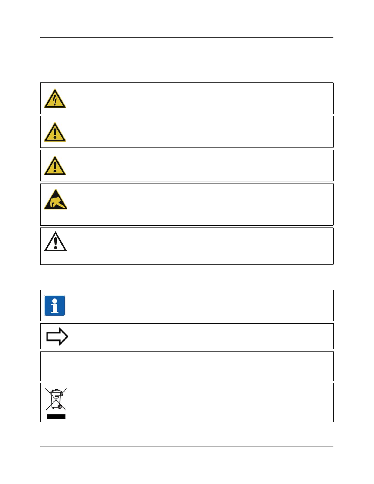
1.2.2 Note signs
DANGER!
This symbol indicates that personal injury caused by electrical shock may occur if the respective precautionary measures are not carried out.
WARNING!
This symbol in connection with the signal word indicates that personal injury may occur if the
respective precautionary measures are not carried out.
CAUTION!
This symbol in connection with the signal word indicates that damage to assets or data loss
will occur if the respective precautionary measures are not taken.
CAUTION!
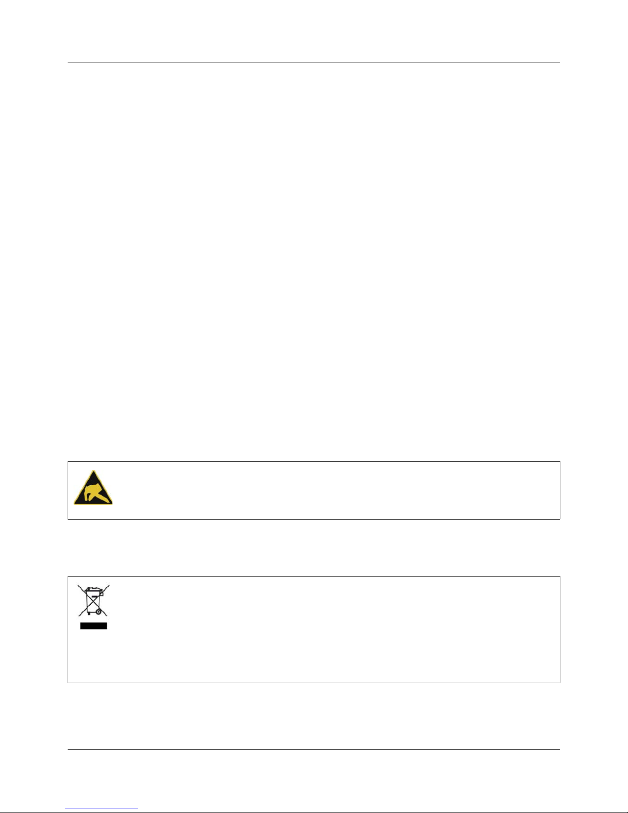
This symbol indicates that components could be destroyed by electrostatic discharge
(ESD = Electro Static Discharge) if the respective cautionary measures are not taken.
Only use the ESD packages intended for this purpose to return device inserts, assembly
groups, or assembly components.
READ DOCUMENTATION!
This symbol – placed on the device – indicates that the associated device documentation
has to be observed. This is necessary to recognize the kind of the potential hazards as
well as the measures to avoid them.
TIP!
This symbol refers to important information about the product, its handling, or additional
use.
REFERENCE!
This symbol refers to further information in other sections, chapters, or manuals.
FURTHER INFORMATION!
This symbol is used in the tables and refers to further information in connection with the
table.
&
DISPOSAL!
This device and the batteries (if installed) must not be disposed in the garbage can after
use! Please ensure that they are disposed properly and in an environmentally friendly
manner.
Page 9

9
1 Introduction
1.2.3 Intended use
The measuring, control, and automation system is intended for use in an industrial environment, as specified in the technical data of the individual system modules. Other uses beyond
those defined are not viewed as intended uses.
The modules are manufactured in compliance with the relevant standards and directives as
well as the applicable safety regulations. Nevertheless, improper use may lead to personal injury or material damage.
To avoid dangers, the modules may only be used:
• For the intended use
• When in good order and condition
• When taking the technical documentation provided into account
Even if a module is used correctly and according to the intended use, it may still pose applica-
tion-related dangers, for example as the result of missing safety devices or incorrect settings.
To avoid incorrect settings, this manual contains relevant safety information and warnings.
These must be complied with.
1.2.4 Qualification of personnel
This document contains the information required to ensure that the measuring, control, and automation system described is used as intended.
It is intended for technically qualified personnel who have received special training and have
the appropriate knowledge in the field of automation technology (measuring and control technology).
Understanding and technically correct observance of the safety informa tion and warnings in the
technical documentation supplied are prerequisites for safe startup as well as safety during operation. Only qualified personnel have the required specialist knowledge to correctly interpret
and implement the safety information and warnings contained in this document in specific situations.
1.3 Acceptance of goods, storage, and transport
1.3.1 Checking the delivery
• Ensure that the packaging and contents are not damaged
• Check that the delivery is complete using the delivery papers and the order details
• Inform the supplier immediately if there is any damage
• Store damaged parts until clarification is received from the supplier
1.3.2 Notes on storage and transport
• Store the module in a dry and clean environment. Observe the admissible ambient conditions (see "Technical data")
• The transport of the module is to be shockproof
• The original packaging provides optimum protection for storage and transport
Page 10
1 Introduction
10
1.3.3 Returning goods
In the event of repair, please return the module in a clean and complete state.
Use the original packaging to return goods.
Accompanying letter for repair
Please include the completed accompanying letter for repair when returning goods.
Do not forget to state the following:
• Description of the application and
• Description of the error that has occurred
The accompanying letter for repair can be downloaded online from the manufacturer's website
(use the search function if necessary).
Protection against electrostatic discharge (ESD)
(ESD = electrostatic discharge)
To prevent damage from ESD, electronic module s or components must be handled, packa ged,
and stored in an ESD-protected environment. Measures against electrostatic discharge and
electrical fields are described in DIN EN 61340-5-1 and DIN EN 61340-5 -2 "Protection of electronic devices from electrostatic phenomena".
When returning electronic modules or components, please note the following:
• Sensitive components must only be packaged in an ESD-protected environment. Workspaces such as this divert electrostatic charges to ground in a controlled manner and prevent static charges due to friction capacities.
• Only use packaging for ESD-sensitive modules/components. These must consist of conductive plastics.
No liability can be assumed for damage caused by ESD.
1.3.4 Disposal
Disposing of the device
Disposing of the packaging material
The entire packaging material (cardboard packaging, inserts, plastic film, and plastic bags) is
fully recyclable.
CAUTION!
Electrostatic charges occur in non-ESD protected environments.
Electrostatic discharges can damage modules or components.
For transport purposes, use only the ESD packaging provided.
DISPOSAL!
Devices and/or replaced parts should not be placed in the refuse bin at the end of their service life as they consist of materials that can be recycled by specialist recycling plants.
Dispose of the device and the packaging material in a proper and environmentally friendly
manner.
For this purpose, observe the country-specific laws and regulations for waste treatment and
disposal.
Page 11

11
1 Introduction
1.4 Device version
1.4.1 Order details
1.4.2 Scope of delivery
1.4.3 Accessories
(1) Basic type
705065 Operating panel with TFT-touchscreen
(2) Basic type extension
0 Standard
(3) Version
8 Standard with factory settings
9 Customer-specific configuration (PLC application)
(4) Screen size (diagonal)
1 8.9 cm (3.5‘‘), operating panel 350
2 14.5 cm (5.7‘‘), operating panel 570
5 26.4 cm (10.4‘‘), operating panel 1040
(5) Technology
0Resistive
(6) Voltage supply
36 DC 24 V +25/-20 %
(7) Extra codes
000 No extra code
Other versions upon request.
(1) (2) (3) (4) (5) (6) (7)
Order code /---/
Order example 705065 / 0 8 - 1 - 0 - 36 / 000
1 operating panel in the ordered version
Retaining brackets with threaded pin for mounting the device (quantity depends on device type)
1 sealing strip for mounting the device (glued in the device and/or enclosed separately)
1 power supply connector for the device
Description Part no.
SD card without OS, min. 128 MB, for memory expansion 00610471
Page 12

1 Introduction
12
1.5 Brief description
The basic version of the measuring, control, and automation system includes the multifunction
panel 840 (TFT-touchscreen) with a screen size of 21.3 cm (8.4") as standard. Among other
features, it offers user administration with access to parameter and configuration data for the
whole system as well as predefined screens for service, controller, program generator, and recording functions (including batch reporting). It is also possible to create customized process
screens that map the actual plant.
The additional operating panels mean that the measuring, control, and automation system can
be configured with even greater flexibility. The operating panels come with CODESYS PLC as
well as target and web visualization, which is implemented by customized PLC applications.
Operation is done within specific process screens. Connecting the panels using CODESYS
project design enables direct access to the PLC variables of the system via CODESYS data
server.
1.6 System requirements
Software
The integration of the operating panels is supported by the measu ring, control, and automation
system from CODESYS Version 3.5 SP3 Patch 9 (from system version 02 onwards).
As of system version 05, CODESYS Version 3.5 SP10 Patch 0 is used.
When selecting the repository package, differentiate between the CODESYS version used.
Chapter 3.1 "General information", page 17
Chapter 3.2.4 "Install the repository package", page 22
Extra code
In order to integrate the operating panels into the measuring, control, and automation system,
the central processing unit requires the extra code 224 (PLC activation according to IEC 611313 CODESYS V3.5).
1.7 Content of this document
This "Connection" chapter in this document explains the connection of an operating panel to
the measuring, control, and automation system via a local network (Ethernet).
The "Configuration" chapter describes how to integrate an operating panel into th e measuring,
control, and automation system by means of CODESYS.
All other technical information can be found in the manufacturer's original documents (www .eaton.com; use search function if necessary). This especially covers safety information, installation, and the electrical connection.
Designation (diagonal
screen measurement)
Manufacturer's original document Document number
Operating panel 350 (3.5-inch) MICRO PANEL XV-102 operating manual MN04802004Z
Operating panel 570 (5.7-inch) MICRO PANEL XV-102 operating manual MN04802004Z
Operating panel 1040 (10.4-
inch)
MICRO PANEL XV-152 operating manual MN04802006Z
Page 13

13
2 Connection
2.1 Installation notes
Requirements for the personnel
• Work on the modules must only be carried out to the extent described and, like the electrical
connection, only by qualified personnel.
• Before plugging and unplugging connection cables ensure that the person performing the
work is electrostatically discharged (e.g. by touching grounded metallic parts).
Cables, shielding, and grounding
• When selecting the cable material, when installing, and when performing the electrical connection of the module, the regulations of DIN VDE 0100 "Erection of power installations with
rated voltages up to 1000 V" and the respective national regulations (e.g. on the basis of
IEC 60364) are to be observed.
• Certain cables must be heat resistant up to at least 80 °C at maximum load. The relevant
instructions in the connection diagram of the affected modules must be observed.
• Route input, output, and supply cables separately and not parallel to one another.
• Only use shielded and twisted probe and interface cables. Do not route the lines close to
current-carrying components or cables.
• For temperature probes, ground the shielding on one side in the control cabinet.
• Do not perform loopthroughs on the grounding cables, but route th e cables individually to a
shared grounding point in the control cabinet; in doing so, ensure that the cables are as
short as possible.
Ensure that the equipotential bonding is correct.
Electrical safety
• Isolate power supply units from the voltage supply on the primary side if there is a risk of
touching parts with dangerous electrical voltage (e.g. 230 V) in the course of work.
• The fuse rating of the power supply units on the primary side should not exceed a value of
10 A (inert).
• With modules with relay or solid state relay outputs, the load circuits can be opera ted with
a dangerous electrical voltage (e.g. 230 V). Disconnect load circuits from the voltage supply
during installation/dismounting and electrical connection.
• In order to prevent the destruction of the relay or solid st ate relay output s in the event of an
external short circuit in the load circuit, the load circuit should be fused to the maximum admissible output current.
• The modules are not suitable for installation in areas with an explosion hazard.
• In addition to a faulty installation, incorrectly set values on the module cou ld also impair the
correct function of the following process. Therefore, ensure that safety devices independent
of the module (e.g. overpressure valves or temperature limiters/monitors) are available and
that it is only possible for qualified personnel to define settings. Please observe the corresponding safety regulations in this context.
NOTE!
These installation notes apply for the entire measuring, control, and automation system and,
on some occasions, are only applicable for a specific module.
The respective connection diagram shows the context.
Page 14

2 Connection
14
References to other information
• The electromagnetic compatibility meets the standards and regulations cited in the technical data.
• The USB device interface and voltage supply in the central processing unit 705 001 are not
electrically isolated. In general, please observe the specifications regarding electrical isolation.
Page 15

15
2 Connection
2.2 LAN connection
The operating panel is connected to the CPU's LAN interface via a local network (Ethernet). A
total of up to four operating panels can be used on the measuring, control, and automation system.
The connection must be established with a commercially available network cable (patch or
crossover cable) that corresponds to at least category 5 and has S/FTP shielding.
System structure
LAN interface of the CPU
(1) LAN interface
Setup
LAN Bus Out
Run
Stop
Reset
Power
Status
Bus Error
Com1
Com2
Com2
2
1
3
4
ON
2
1
3
4
ON
Com1
(1)
Page 16

2 Connection
16
Page 17

17
3 Configuration
3.1 General information
The functionality of the operating panel is implemented using a PLC application that runs on
the operating panel. The PLC application must be programmed with the CODESYS programming system for this.
A data server on the operating panel is responsible for the data exchange betwee n system and
operating panel.
The following instructions describe the basic procedure for programming with CODESYS. An
analog value on the operating panel is represented by means of an example.
The "CODESYS repository package - operating panels" is required as well as CODESYS V ersion V3.5 SP3 Patch 9. The repository package has been part of the sco pe of delive ry of CPU
705001 since system version 02, and is supplied on the MiniDVD along with the setup prog ram
(incl. the CODESYS version).
The repository package can also be downloaded for free on the JUMO website (search for
705001, click on the "Products" link and open the "Software" drop-down menu):
NOTE!
As of system version 05, repository package 705065_3_5_10_0_Eaton.package has to be
used.
NOTE!
As of system version 05, additional operating panels are supported (EATON, EXOR, ASEM)
which are not yet decscribed in this document (see current price sheet 705065).
Page 18

3 Configuration
18
3.2 Creating a PLC application
The following description requires that a setup project has been created and transferred to the
system in advance with the measuring, control, and automation system's setup program. The
system must now be extended to include an operating panel, which has been connected in advance, as described in the "Connection" chapter.
3.2.1 Starting CODESYS
CODESYS is started from the setup program.
Step Activity
1 Setup program: Project > Project settings > PLC > Start CODESYS
Important:
- PLC application = Own PLC application
- With I/O mapping of the modules
Page 19

19
3 Configuration
3.2.2 Mapping a variable
This example shows a temperature value on the operating panel next to an input of the fourchannel analog input module (Analog_In_4x). Input 1 (AI01) is assigned to a "Temp _1" variable
in this case.
NOTE!
Input values, such as the value for the analog input module's input in this example, can be
represented on the operating panel, but cannot be changed. Internal variables, on the other
hand, can also be edited on the operating panel (e.g. setpoint values).
Step Activity
1 Open "Analog_In_4x" module in device tree with a double click
2 "System bus I/O mapping" tab, analog inputs (expand view by clicking on "+"): open
the variable by double-clicking in the "Variable" column on the relevant row (AI01
channel) and provide the variable name (here: Temp_1)
Page 20

3 Configuration
20
3 Open "mTron_T_User (PRG)" program in device tree with a double click
4 Supplement the program with the "Temp_1" variable (= call up variable)
5 Compile the data source's PLC application and transfer to the CPU
The data source's PLC application must be compiled and downloaded in order for
the data source's variables to be available (see Step 4 in Chapter 3.2.7 "Add data
server and data source", page 26).
Step Activity
Page 21

21
3 Configuration
3.2.3 Select CODESYS feature set
Step Activity
1 Tools > Options...
2 Features > Predefined feature sets...
3 Select the "Professional" feature set and accept with "OK"
4 Also leave the previous dialog (see Step 2) by pressing "OK"
Page 22

3 Configuration
22
3.2.4 Install the repository package
NOTE!
The repository package shown in this example affects system versions 02 to 04. As of system
version 05, repository package 705065_3_5_10_0_Eaton.package has to be used.
Step Activity
1 Tools > Package manager...
2 Install...
3 Select the package in the file directory and open it (or open with a double-click)
➥ The package is installed. Follow the instructions during installation (Select "Com-
plete installation" as the installation type).
➥ The package appears in the package manager after installing successfully (press
"Update" button if necessary):
Page 23

23
3 Configuration
3.2.5 Insert the operating panel into the device tree
4 Close the package manager
Step Activity
Step Activity
1 mTRON_T_boot project (context menu) > Add device
2 Select XV100 device from the list and provide a name (here: XV100)
The operating panels now available (350, 570, and 1040) all correspond with the
XV100 device (further panels upon request).
Page 24

3 Configuration
24
3 Click on the "Add device" button and then end the dialog by clicking "Close"
➥ The operating panel is added to the CPU in the device tree:
4 Set the operating panel as an active application (context menu)
Step Activity
Page 25

25
3 Configuration
3.2.6 Transfer current firmware
If necessary, the operating panel's operating system must be updated. This involves transferring the current firmware to the operating panel via an FTP connection.
Step Activity
1 Operating panel: Start FTP server:
Start > Programs > Communication > FTP server
(provide the IP address first if necessary or conduct assignment via DHCP)
➥ The FTP server is active:
2 Open the XV100 with a double click and switch to the "Firmware" tab.
3 Start firmware update in CODESYS.
➥ The se tu p ass ista n t star ts.
Page 26

3 Configuration
26
3.2.7 Add data server and data source
4 Follow the instructions in the setup assistant. The following settings are made in
sequence there:
• Select installation type: "FTP installation"
• FTP parameter: IP address of the operating panel, enter username and
password
• Device type: select "XV-1xx"
• Select components
➥ After closing the firmware installation and rebooting the operating panel, the
"PLC3" symbol appears on the operating panel's screen.
Step Activity
NOTE!
This example applies to system versions 02 to 04. As of system version 05, the term "Data
Server" has been changed to "Data Source Manager".
Step Activity
1 Add data server:
Application (context menu) > Add object > Data server
2 Add data source:
DataServer (context menu) > Add object > Data source...
Page 27

27
3 Configuration
3 Select and add CPU (application) as the data source
4 Select data source's "Temp_1" variable
The data source's PLC application must be compiled in advanced and downloaded
in order for the data source's variables to be available (see Step 5 in Chapter 3.2.2
"Mapping a variable", page 19).
Step Activity
Page 28

3 Configuration
28
5 Search for the data source on the network by means of the MAC address (target
device: CPU). This avoids problems that may occur based on gat ew ay se ttin g s in
networks.
DataServer > DataSource > "Communication" tab: Search for target device via network scan (search mode: exact device found)
Click on "From device":
➥ The following fields are automatically completed by CODESYS using the data of
the CPU to which an online connection was last established (activate node name
with a checkmark):
Step Activity
Page 29

29
3 Configuration
3.2.8 Configure visualization
Step Activity
1 Add visualization to the operating panel
2 Change the name of the visualization if necessary
Page 30

3 Configuration
30
3 Open the target visualization by double-clicking
4 Choose setting
Ideal size: client width and height must correspond with the operating panel's scr een
resolution (see Chapter 4 "Technical data", page 37).
5 "Visualization" tab: insert rectangle
Step Activity
Page 31

31
3 Configuration
6 Set the display format of the text variables: %3.2g
% = variable, 3 = pre-decimal characters, .2 = post-decimal characters, g = float
value in exponential representation (i = integer value, b = Boolean value)
7 Assign text variable
Use input assistance ("..." button): select "Temp_1" and accept with "OK":
➥
Step Activity
Page 32

3 Configuration
32
3.2.9 Close CODESYS project and save configuration
Step Activity
1 Close project
➥ The PLC application is transferred to the setup program again.
2 Setup program: Follow the note to end CODESYS, and close with "OK"
The operating panel's CODESYS project planning (PLC application) is not transferred to the system and thus is not saved on the CPU, in contrast with the system's
PLC application (see Step 5). The setup file must therefore be saved in the setup
program so that the operating panel's PLC application is also availabl e for later mo difications (see Step 6).
3 Setup program: Follow the note to end CODESYS, and close with "OK"
4 In the setup program, exit the "project settings" dialog with "OK"
5 Setup program: transfer the project to the system (device)
Page 33

33
3 Configuration
3.2.10 Start CODESYS for debugging
CODESYS is started from the setup program (using the previously saved setup file).
6 Setup program: save the setup file (or save under a different name).
Step Activity
Step Activity
1 Setup program: Project > Project settings > PLC > Start CODESYS for debugging
Important:
- PLC application = Own PLC application
Page 34

3 Configuration
34
3.2.11 Load configuration in operating panel
Step Activity
1 Log into operating panel
2 Select operating panel from communication settings
3 Press the "Start" button
➥ The analog value of the "Temp_1" variable is displayed on the operating panel:
Page 35

35
3 Configuration
3.2.12 Create a boot application
A boot application must be created for the application to continue to be available in the operating panel after a voltage interruption.
Step Activity
1 Create a boot application
Page 36

3 Configuration
36
3.2.13 Close CODESYS project
Step Activity
1 Close project (or end CODESYS)
➥ The PLC application is transferred to the setup program again.
2 Setup program: Follow the note to end CODESYS, and close with "OK"
3 In the setup program, exit the "project settings" dialog with "OK"
Page 37

37
4 Technical data
4.1 Operating panel 350 (type 705065/0x-1...)
Screen type TFT color screen
Touch technology Resistive
Screen size (diagonal) 8.9 cm (3.5‘‘)
Resolution 320 × 240 pixel
Number of colors 64k
Contrast typ. 300:1
Brightness typ. 250 cd/m
2
Background lighting LED (dimmable by software)
Voltage supply nom. DC 24 V +25/-20 % SELV
Power consumption max. 5 W
Current inrush 1.5 A
2
s
Assembly type Insertion in panel cut-out
Case type Plastic
Front panel type Plastic with neutral de sign foil (fully enclosed)
Dimensions (W × H × D) 136 mm x 100 mm x 30 mm
Front panel depth 5 mm
Mounting depth 25 mm
Panel cut-out 123 mm x 87 mm (± 1 mm)
Weight 0.3 kg
Protection type IP65 (front side), IP20 (rear side)
Ambient temperature range 0 to 50 °C
Storage temperature range -20 to +60 °C
Resistance to climatic condi-
tions
Relative humidity 10 to 95 %, non-condensing
Page 38

4 Technical data
38
The complete technical data as well as further technical information can be found in the manufacturer's original documents (www.eaton.com; use search function).
Type 705065/0x-1...: search for „XV-102“
Page 39

39
4 Technical data
4.2 Operating panel 570 (type 705065/0x-2...)
Screen type TFT color screen
Touch technology Resistive
Screen size (diagonal) 14.5 cm (5.7‘‘)
Resolution 640 × 480 pixels
Number of colors 64k
Contrast typ. 300:1
Brightness typ. 250 cd/m
2
Background lighting LED (dimmable by software)
Voltage supply nom. DC 24 V +25/-20 % SELV
Power consumption max. 10 W
Current inrush 1.5 A
2
s
Assembly type Insertion in panel cut-out
Case type Plastic
Front panel type Plastic with neutral de sign foil (fully enclosed)
Dimensions (W × H × D) 170 mm x 130 mm x 39 mm
Front panel depth 5 mm
Mounting depth 34 mm
Panel cut-out 157 mm x 117 mm (± 1 mm)
Weight 0.6 kg
Protection type IP65 (front side), IP20 (rear side)
Ambient temperature range 0 to 50 °C
Storage temperature range -20 to +60 °C
Resistance to climatic condi-
tions
Relative humidity 10 to 95 %, non-condensing
Page 40

4 Technical data
40
The complete technical data as well as further technical information can be found in the manufacturer's original documents (www.eaton.com; use search function).
Type 705065/0x-2...: search for „XV-102“
Page 41

41
4 Technical data
4.3 Operating panel 1040 (type 705065/0x-5...)
Screen type TFT color screen
Touch technology Resistive
Screen size (diagonal) 26.4 cm (10.4‘‘)
Resolution 640 × 480 pixels
Number of colors 64k
Contrast typ. 300:1
Brightness typ. 250 cd/m
2
Background lighting LED (dimmable by software)
Voltage supply nom. DC 24 V +25/-20 % SELV
Power consumption max. 12 W
Current inrush 1.5 A
2
s
Assembly type Insertion in panel cut-out
Case type Metal
Front panel type Metal with neutral design foil (fully enclosed)
Dimensions (W × H × D) 345 mm x 260 mm x 54 mm
Front panel depth 5 mm
Mounting depth 49 mm
Panel cut-out 329 mm x 238 mm (± 1 mm)
Weight 3.0 kg
Protection type IP65 (front side), IP20 (rear side)
Ambient temperature range 0 to 50 °C
Storage temperature range -20 to +60 °C
Page 42

4 Technical data
42
The complete technical data as well as further technical information can be found in the manufacturer's original documents (www.eaton.com; use search function):
Type 705065/0x-5...: search for „XV-152“
Resistance to climatic conditions
Relative humidity 10 to 95 %, non-condensing
Page 43

Page 44

JUMO GmbH & Co. KG JUMO Instrument Co. Ltd. JUMO Process Control, Inc.
Street address:
Moritz-Juchheim-Straße 1
36039 Fulda, Germany
JUMO House
Temple Bank, Riverway
Harlow, Essex, CM20 2DY, UK
6733 Myers Road
East Syracuse, NY 13057, USA
Delivery address:
Mackenrodtstraße 14
36039 Fulda, Germany
Phone:
Fax:
Email:
Internet:
+44 1279 63 55 33
+44 1279 62 50 29
sales@jumo.co.uk
www.jumo.co.uk
Phone:
Fax:
Email:
Internet:
+1 315 437 5866
+1 315 437 5860
info.us@jumo.net
www.jumousa.com
Postal address:
36035 Fulda, Germany
Phone:
Fax:
Email:
Internet:
+49 661 6003-0
+49 661 6003-607
mail@jumo.net
www.jumo.net
 Loading...