

Page 1
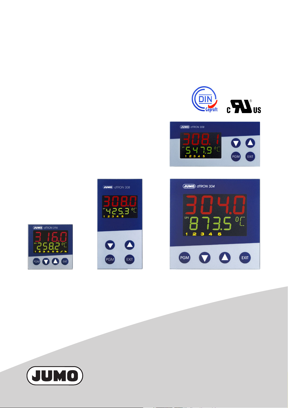
JUMO dTRON 304/308/316
Compact Controller with program function
Type 703043
Type 703041 Type 703042 Type 703044
B 70.3041.0
Operating Manual
2010-04-30/00442056
Page 2

)
E
Please read this operating manual before commissioning the instrument. Keep the manual in a
place which is accessible to all users at all times.
Your comments are appreciated and may help us in improving this manual.
All necessary settings are described in this operating manual. Manipulations not described in the
manual or expressly forbidden will jeopardize your warranty rights. Please contact the nearest subsidiary or the head office, should you encounter problems.
This manual is valid from instrument software version 192.02.05.
It appears by simultaneously pressing the and keys.
When accessing the inner parts of the unit and returning modules, assemblies or components,
please observe the regulations accordings to EN 61340-5-1 and EN 61340-5-2 „Protection of electrostatic sensitive devices“. Only use ESD packaging for transport.
Please note that we cannot accept any liability for damage caused by ESD.
ESD=Electro Static Discharge
Page 3

Contents
1 Introduction 7
1.1 Description .................................................................................................... 7
1.2 Typographical conventions ......................................................................... 8
2 Identifying the instrument version 9
2.1 Type designation .......................................................................................... 9
2.2 Scope of delivery ........................................................................................ 10
2.3 Accessories ................................................................................................ 10
3 Mounting 11
3.1 Mounting site and climatic conditions ..................................................... 11
3.2 Dimensions ................................................................................................. 11
3.2.1 Type 703044 ................................................................................................. 11
3.2.2 Type 703042/43 ............................................................................................ 12
3.2.3 Type 703041 ................................................................................................ 12
3.3 Side-by-side mounting .............................................................................. 13
3.4 Fitting in position ........................................................................................ 13
3.5 Removing the controller module .............................................................. 14
4 Electrical connection 15
4.1 Installation notes ........................................................................................ 15
4.2 Electrical isolation ...................................................................................... 16
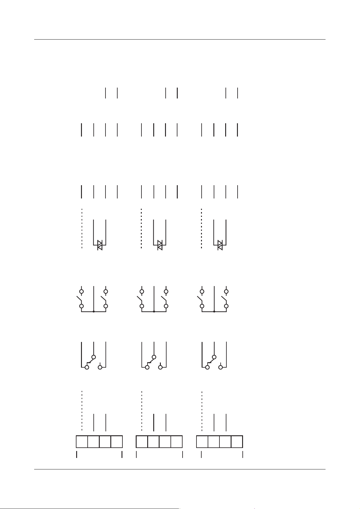
4.3 Connection diagrams ................................................................................. 17
4.3.1 Type 703041 ................................................................................................. 17
4.3.2 Type 703042/43/44 ...................................................................................... 20
4.3.3 Termination resistor for the RS422/485 serial interface ............................... 24
4.3.4 Connection of the PROFIBUS-DP connector .............................................. 24
Page 4

Contents
5 Operation 25
5.1 Displays and controls ................................................................................ 25
5.2 Level concept ............................................................................................. 26
5.3 Level inhibit ................................................................................................. 27
5.4 Entries and operator prompting ............................................................... 28
5.5 Fixed-setpoint controller (ex-factory) ....................................................... 29
5.6 Program controller ..................................................................................... 30
5.6.1 Entering programs ........................................................................................ 30
5.6.2 Operation ..................................................................................................... 32
5.6.3 Shifting the program profile .......................................................................... 33
6 Operator level 35
7 Parameter level 37
8 Configuration 39
8.1 Analog inputs “InP” .................................................................................... 41
8.1.1 Customized fine tuning ................................................................................ 43
8.2 Controller “Cntr” ........................................................................................ 45
8.3 Generator “Pro” .......................................................................................... 47
8.4 Limit comparators “LC” ............................................................................. 50
8.5 Outputs “OutP” ........................................................................................... 54
8.6 Binary functions “binF” .............................................................................. 56
8.7 Display “diSP” ............................................................................................. 59
8.8 Timer “tFct” ................................................................................................ 61
8.9 Interfaces “IntF” ......................................................................................... 62
9 Tuning (optimization) 63
9.1 Autotuning (self-optimization) ................................................................... 63
9.2 Check of the tuning .................................................................................... 66
Page 5

Contents
10 Extra codes 67
10.1 Math and logic module .............................................................................. 67
10.2 Difference, humidity or ratio controller .................................................... 67
11 Retrofitting of modules 69
12 Appendix 71
12.1 Technical data ............................................................................................. 71
12.2 Alarm messages ......................................................................................... 74
13 Index 75
Page 6

Contents
Page 7
1.1 Description
The controller series consists of four freely programmable instruments in different DIN
formats for controlling temperature, pressure and other process variables.
As a temperature controller TR
generating plants to control the temperature of liquids or gases (mode of action: 1B).
The high-contrast, multicolor LCD display for process value, setpoint and operator
prompting contains two four-digit 7-segment displays, two single-character 16segment displays, display of the active setpoints, six status indicators, and displays
for the unit, ramp function and manual operation.
Just four keys on the front panel are needed for operation, parameterization and
configuration. The instruments can be used as 2-state, 3-state, modulating or
continuous controllers. The controller software includes a program or ramp function,
parameter set changeover, two autotuning (self-optimization) procedures, a math and
logic module, as well as 4 limit comparators.
Linearizations for the usual transducers are stored, and a customer-specific
linearization table can be programmed.
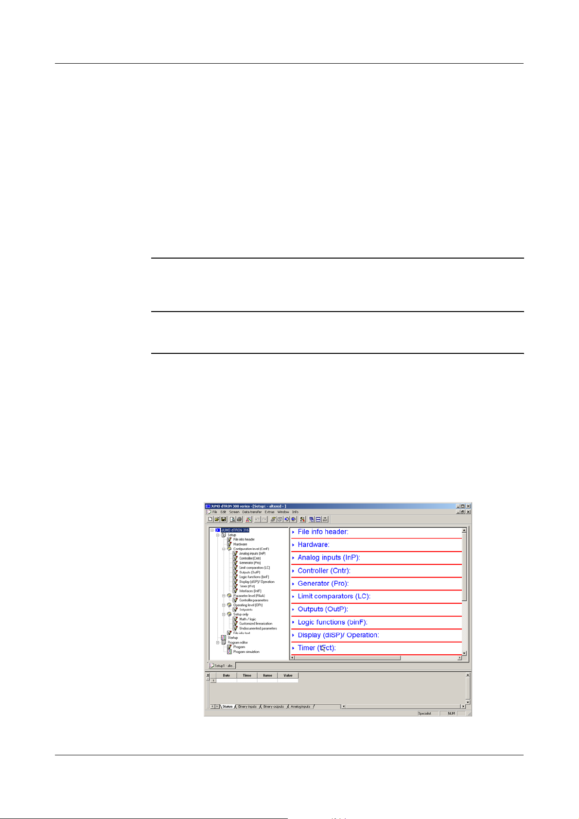
A setup program is available for user-friendly configuration from a PC.
An RS422/485 or a Profibus-DP interface can be used to integrate the instrument into
a data network.
The electrical connection is made at the back of the instrument, via screw terminals.
1 Introduction
1
according to EN 14597 the devices are used in heat-
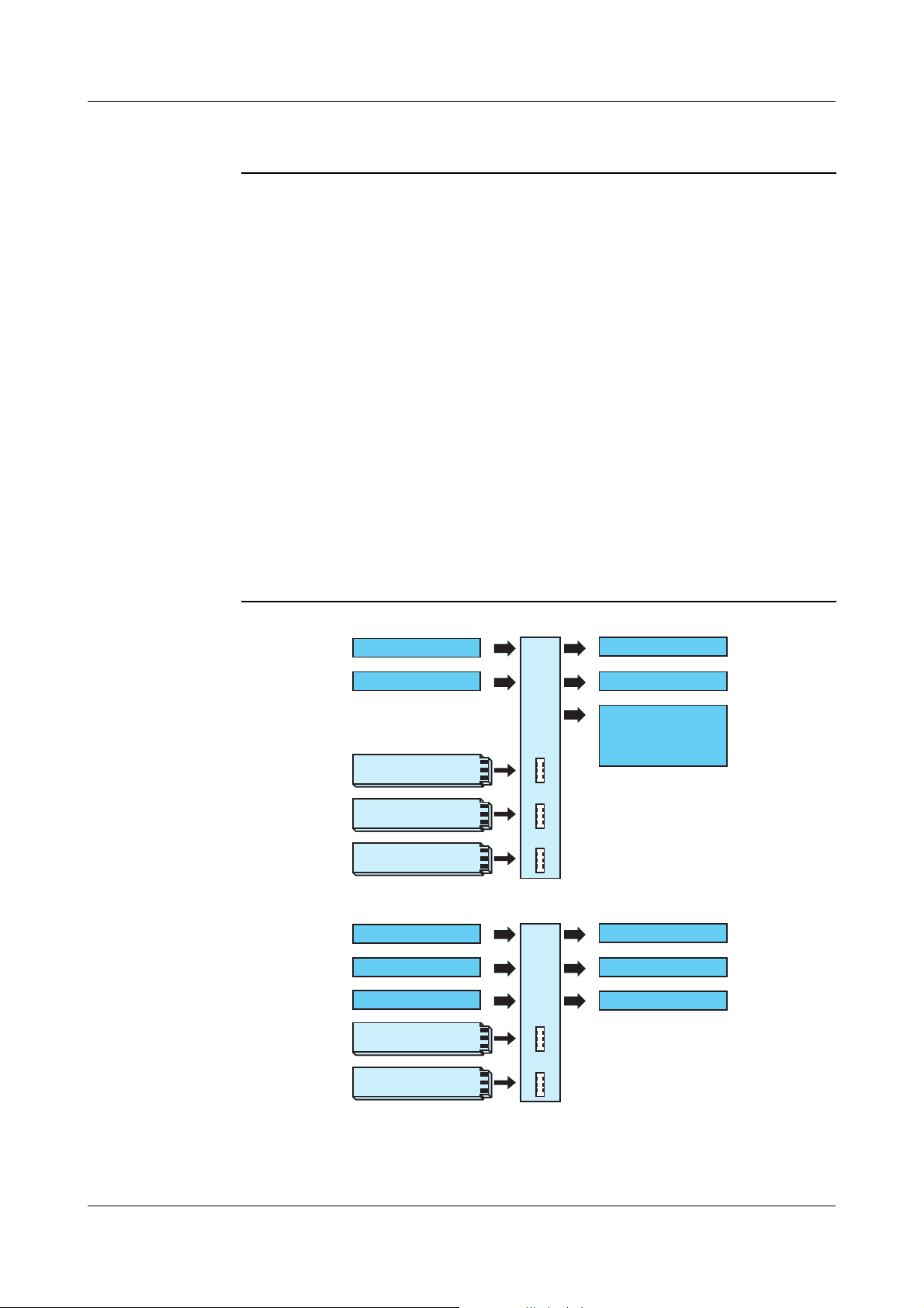
Analog input
2 binary inputs
Option 1
Option 2
Option 3
Analog input
Binary input
Binary input
Option 1
Type 703042/43/44
2 relays (changeover)
2 logic outputs
Supply voltage
17 V / 20 mA
for 2-wire
transmitter
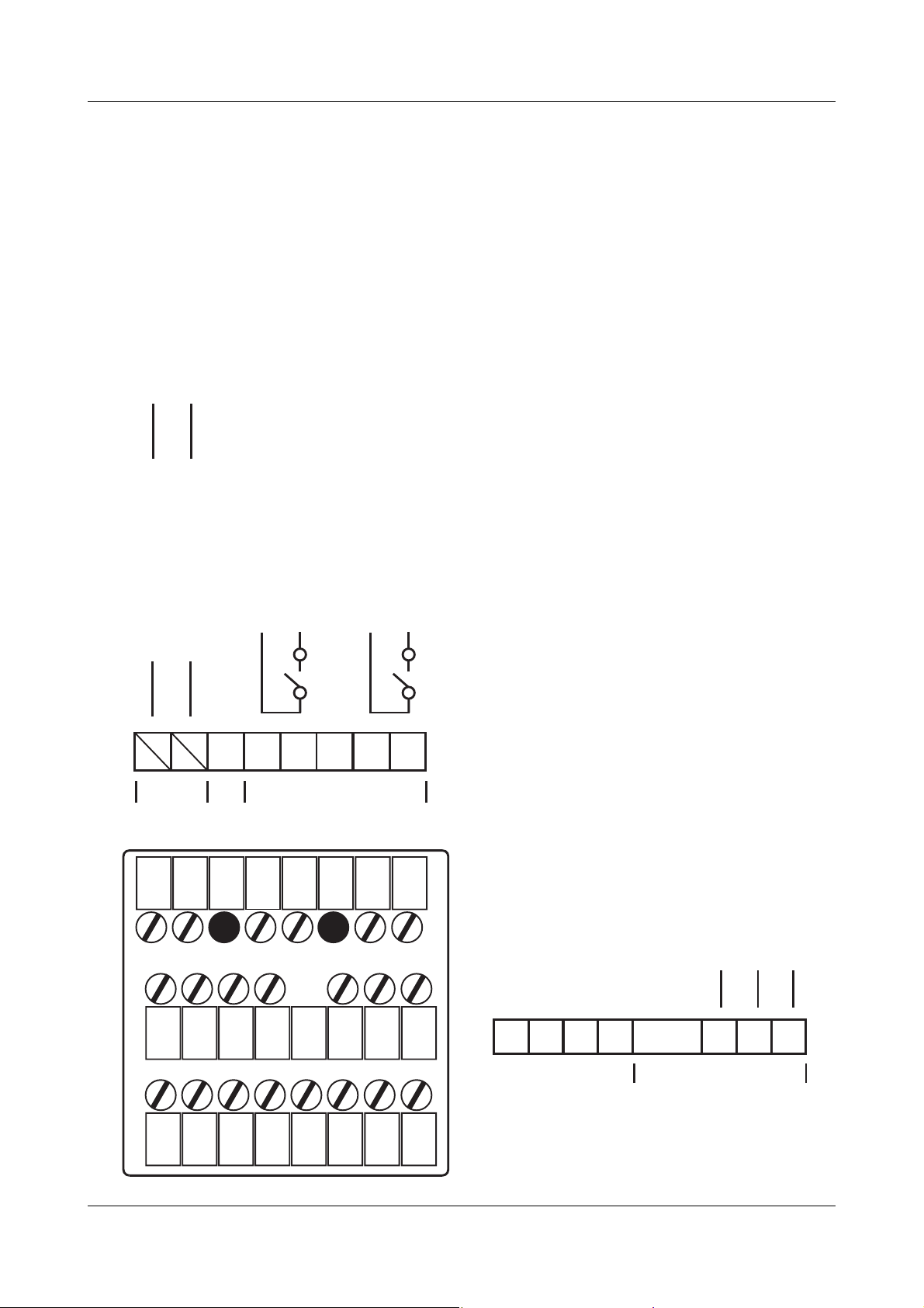
Type 703041 (48mm x 48mm)
2 relays (make)
or
or
Logic output
Logic output
Option 2
1. For more detailed explanation, see EN 14597
7
Page 8

1 Introduction
1.2 Typographical conventions
Warning signs
Note signs
V
*
E
H
v
Danger This symbol is used when there may be danger to
personnel if the instructions are ignored or not followed
correctly!
Caution This symbol is used when there may be damage to
equipment or data if the instructions are ignored or not
followed correctly!
Caution This symbol is used where special care is required when
handling components liable to damage through
electrostatic discharge.
Note This symbol is used when your special attention is drawn
to a remark.
Reference This symbol refers to further information in other operating
instructions, chapters or sections.
H
Representation Menu items Texts from the setup program are shown in italics, for
Action
instruction
Blinking
display
This symbol indicates that an action to be performed is
described.
The individual steps are marked by this asterisk, e.g.
h Press
example: edit program.
I
I
I
I
I
I
I I I I I I I I I I I I I
I
I
IIIIIIIIIIII
I
X
I
I
I
I
I
I
I
I
I
8
Page 9
2 Identifying the instrument version
2.1 Type designation
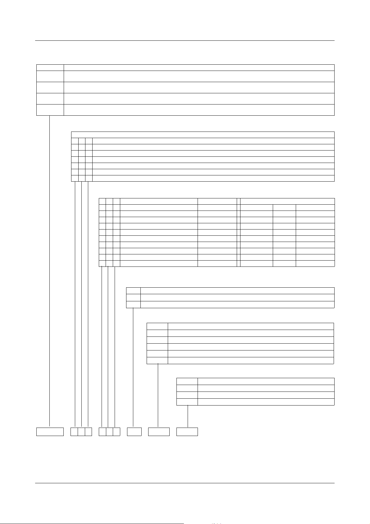
Basic type
703041 JUMO dTRON 316, format 48mm x 48mm
703042 JUMO dTRON 308, format 48mm x 96 mm (portrait format)
703043 JUMO dTRON 308, format 96mm x 48 mm (landscape format)
703044 JUMO dTRON 304, format 96mm x 96mm
incl. 1 analog input, 2 relay outputs and 2 binary inputs or 2 logic outputs
incl. 1 analog and 2 binary inputs, 2 relays and 2 logic outputs
incl. 1 analog and 2 binary inputs, 2 relays and 2 logic outputs
incl. 1 analog and 2 binary inputs, 2 relays and 2 logic outputs
Basic type extensions
1 Basic type 1
Version
8 standard, with factory settings
9 programming to customer specification
logic outputs (2 are available as standard)
10/12V
20/18V
Type 703042/43/44
1. 2. 3. Option slot Max. number Max. number Option 1 Option 2
0 0 0 not used XX
1 1 1 analog input 2 (universal) 1 1 X X
2 2 2 relay (changeover) 2 1 X 3 3 3 2 relays (make contact) 2 1 X 4 4 4 analog output 2 2 X X
5 5 5 2 binary inputs 2 1 X X
6 6 6 solid-state relay 1 A 2 2 X X
7 7 7 RS422/485 interface 1 1 X X
8 8 8 Profibus-DP interface 1 1 X X
X = available in this option slot, - = not available in this option slot
Supply
2 3 110 — 240V AC -15/+10%, 48 — 63Hz
2 5 20 — 30V AC/DC, 48 — 63Hz
Extra codes
000none
214math and logic module
217ratio controller (requirement: 2 analog inputs)
218difference controller (requirement: 2 analog inputs)
2 1 9 humidity controller (requirement: 2 analog inputs)
Type 703041 (no option 3)
/1 – – / ,
703041 / 1 8 1 – 1 4 0 – 2 3 / 0 0 0 ,
Approvals
000none
056DIN EN 14597
dTRON 304 with GL approval on request
9
Page 10
2 Identifying the instrument version
2.2 Scope of delivery
- 1 controller
-1 seal
- mounting brackets
- Operating Manual B70.3041.0 in DIN A6 format
1 CD with demo software and PDF documents in DIN A4 format (operating manual
and further documentation) can be ordered separately.
The individual documents and programs are available for dowload from www.jumo.net
(the software can be enabled for a charge.)
2.3 Accessories
PC interface PC interface with TTL/RS232 converter and adapter (socket connector) for setup
program
Sales No. 70/00350260
USB interface PC interface with USB/TTL converter, adapter (socket conector) and adapter (pins)
Sales No. 70/00456352
Setup
program
Setup program with program editor and Startup
Sales No. 70/00445443
Hardware requirements:
- PC Pentium 100 or compatible
- 128 MB RAM, 30 MB free fixed disc memory
-CD ROM drive
- free serial or USB interface
Software requirements:
Microsoft
1
Windows 98/NT4.0/ME/2000/XP
10
1. Microsoft is a registered trademark of Microsoft Corporation
Page 11
3.1 Mounting site and climatic conditions
The conditions on the mounting site must meet the requirements specified in the
technical data. The ambient temperature on the mounting site can be from 0 to 55 °C,
with a relative humidity of not more than 90 %.
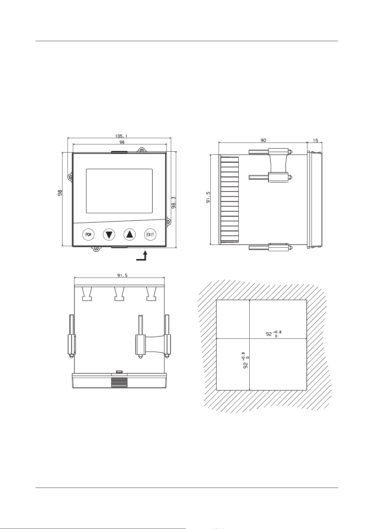
3.2 Dimensions
3.2.1 Type 703044
3 Mounting
Setup plug
Panel cut-out
11
Page 12
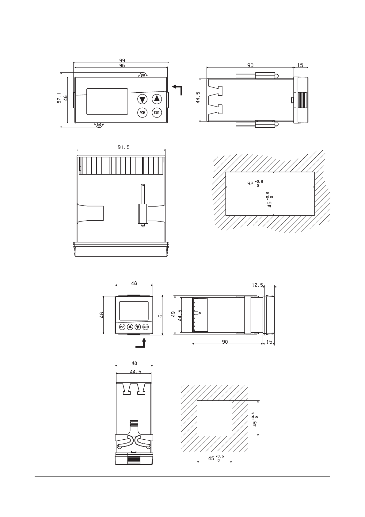
3 Mounting
3.2.2 Type 703042/43
Setup plug
Panel cut-out
3.2.3 Type 703041
Setup plug
Panel cut-out
12
Page 13
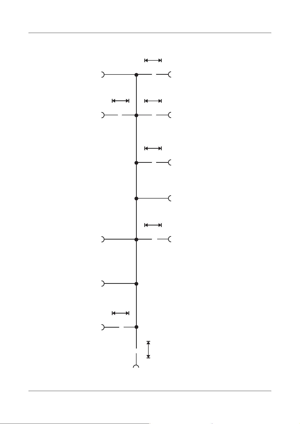
3.3 Side-by-side mounting
Minimum spacing of panel cut-outs
Type horizontal vertical
without setup plug:
703041 (48mm x 48mm)
703042 (portrait format: 48mm x 96mm))
703043 (landscape format: 96mm x 48mm)
703044 (96mm x 96mm)
with setup plug (see arrow):
703041 (48mm x 48mm)
703042 (portrait format: 48mm x 96mm))
703043 (landscape format: 96mm x 48mm)
703044 (96mm x 96mm)
3.4 Fitting in position
Type 703042/43/44 h Fit the seal that is supplied onto the
instrument body.
3 Mounting
11mm
11mm
30mm
11mm
11mm
11mm
65mm
11mm
30mm
30mm
11mm
30mm
65mm
65mm
11mm
65mm
h Insert the controller from the front into
the panel cut-out.
h From behind the panel, slide the
mounting brackets into the guides on
the sides of the housing.
The flat faces of the mounting brackets
must lie against the housing.
h Push the mounting brackets up to the
back of the panel, and tighten them
evenly with a screwdriver.
Type 703041 h Fit the seal that is supplied onto the
instrument body.
h Insert the controller from the front into
the panel cut-out.
h From the back of the panel, push the
mounting frame onto the instrument
body and press it against the back of
the panel, compressing the springs,
until the latches snap into the notches
provided and it is firmly fixed in position.
Care of the front
panel
The front panel can be cleaned with normal commercial washing, rinsing and cleaning
agents. It has a limited resistance to organic solvents (e.g. methylated spirits, white
spirit, P1, xylol etc.). Do not use high-pressure cleaning equipment.
13
Page 14

3 Mounting
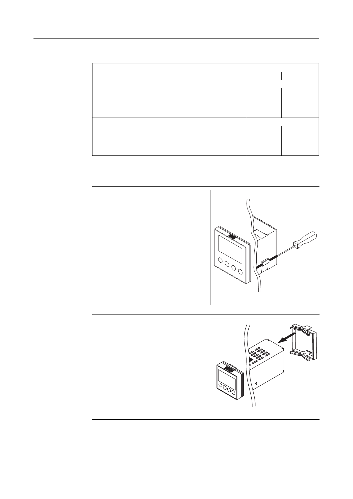
3.5 Removing the controller module
The controller module can be removed from its housing for servicing.
h Press together the knurled areas
(top and bottom, or left and right for
landscape format) and pull out the
controller module.
H
When inserting the controller module, make sure that the latches (below the
knurled areas) snap into place.
14
Page 15

4.1 Installation notes
- The choice of cable, the installation and the electrical connection must conform to
the requirements of VDE 0100 “Regulations on the Installation of Power Circuits
with Nominal Voltages below 1000 V” or the appropriate local regulations.
- The electrical connection must only be carried out by qualified personnel.
- The instrument shall be operated by mains protected with a branch circuitry
overcurrent protection device not more than 20 Amps.
For servicing/repairing a Disconnecting Device shall be provided to disconnect all
conductors.
- The load circuit must be fused for the maximum relay current, in order to prevent
the output relay contacts becoming welded in the event of a short circuit.
- Electromagnetic compatibility conforms to the standards and regulations cited in
the technical data.
- Run input, output and supply cables separately and not parallel to one another.
- Sensor and interface cables should be shielded cables with twisted conductors.
Do not run them close to current-carrying components or cables. Ground the
shielding on one side.
- Do not connect any additional loads to the supply terminals of the instrument.
- The instrument is not suitable for use in areas with an explosion hazard (Ex areas).
- In addition to faulty installation, incorrect settings on the controller (setpoint, data
of the parameter and configuration levels, internal alterations) can also interfere
with the correct operation of dependent processes, or even cause damage. Safety
devices should always be provided that are independent of the controller (such as
overpressure valves or temperature limiters/monitors) and only capable of adjustment by specialist personnel. Please observe the relevant safety regulations for
such matters. Since adaptation (self-optimization) can not be expected to handle
all possible control loops, an unstable parameterization is theoretically possible.
The stability of the actual value that is produced should therefore be checked.
4 Electrical connection
.
The electrical connection must only be
carried out by specialist personnel.
V
H
Conductor cross-sections and core-end ferrules for installation
Without core-end ferrule 0.34mm
Core-end ferrule, no lip 0.25mm
Core-end ferrule, lip up to 1.5mm
Core-end ferrule, lip above 1.5mm
Twin ferrule with lip 0.25mm
The instrument version can be
identified by the type code.
Minimum
cross-section
2
0.25mm
2
1.5mm
Maximum
cross-section
2
2
2
2
2
2.5mm
2.5mm
1.5mm
2.5mm
1.5mm
2
2
2
2
2
Min. length of
core-end ferrule
10mm
(stripped)
10mm
10mm
12mm
12mm
15
Page 16
4 Electrical connection
4.2 Electrical isolation
3800 V AC
Input 1
Relay outputs
»
30 V AC
50 V DC
Input 2 Solid-state relay outputs
3800 V AC
»
»
30 V AC
50 V DC
Analog outputs
»
Logic outputs
30 V AC
50 V DC
Binary inputs
Setup
interface
RS422/485
PROFIBUS-DP
Supply voltage for
2-wire transmitter
»
30 V AC
50 V DC
»
»
3800 V AC
Supply voltage
16
Page 17
4.3 Connection diagrams
4.3.1 Type 703041
L-
L+
4 Electrical connection
Supply and outputs - terminal strip 3
3
110—240V AC 20—30V AC/DC
L1
L+
L1
N
L1(L+)
122
N
L-
3
Supply
3
N(L-)
230V/3A Binary output 1 (Out1)
P
S
5
4
6
230V/3A Binary output 2 (Out2)
P
S
7
8
Relays
8
3
4
4
5
6
6
7
7
8
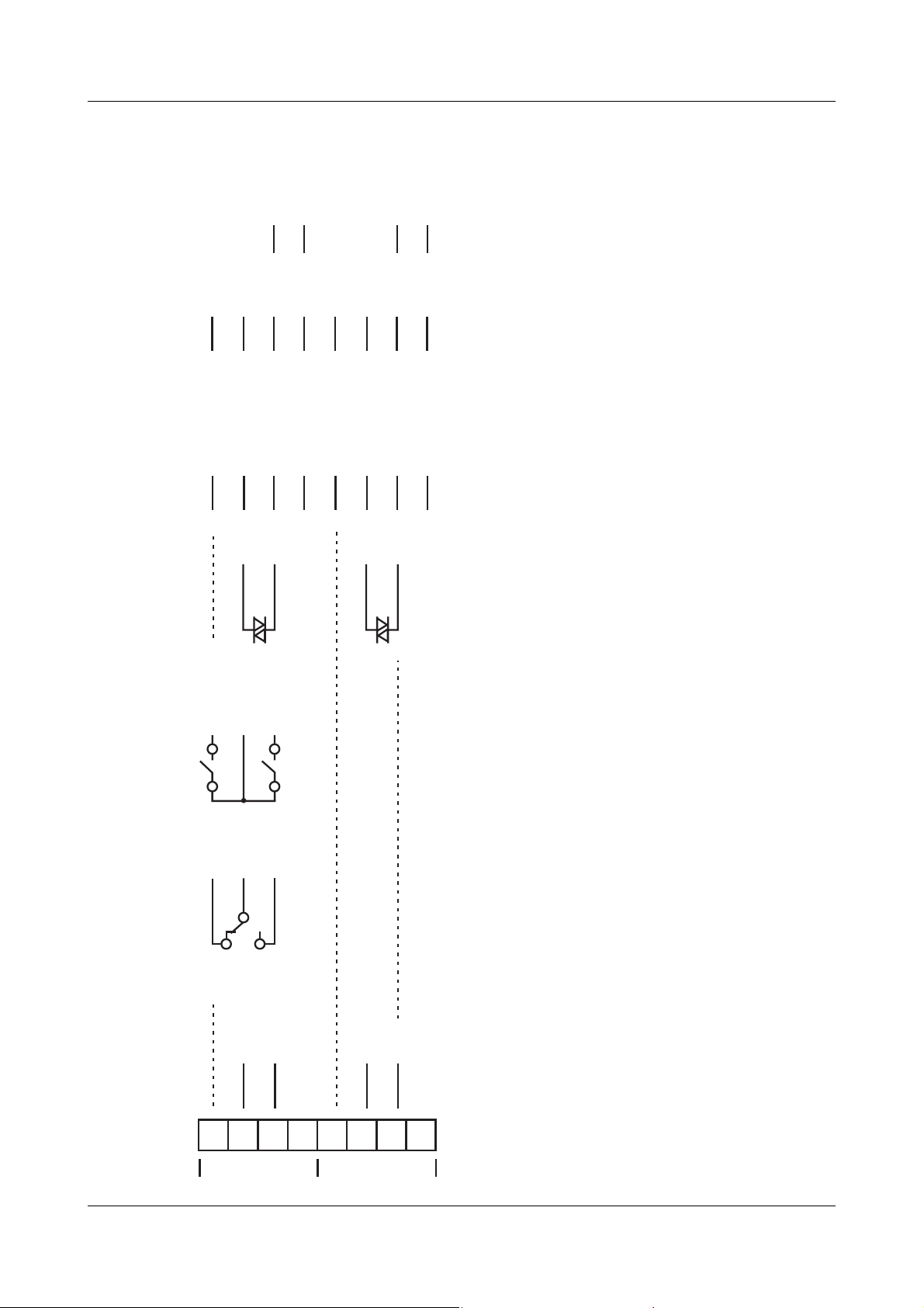
Outputs - terminal strip 2
1
243
Logic output level 12V or 18V
(see type code)
As an alternative to binary inputs 1 and 2
(configurable)!
Binary output 3
Binary output 4
Out3 (+)
Out4 (+)
GND (-)
6
7
8
Logic
112
3
4
5
6
7
8
17
Page 18
4 Electrical connection
RxD/TxD +
RS485
PROFIBUS RS422
RxD +
RxD -
TxD +
VP (+5 V)
RxD/TxD-P (B)
RxD/TxD-N (A)
RxD/TxD -
TxD -
RxD +
DGND
VP (+5 V)
RxD/TxD +
RxD -
TxD +
RxD/TxD-P (B)
RxD/TxD-N (A)
RxD/TxD -
TxD -
DGND
Solid-state
relay
Out5
2 relays
(n.o. make)
Ö
Relay
(changeover)
Analog
output
Binary output 6
Binary output 5
(Out5)
Out8
Binary output 5+8
(Out5+Out8)
P
S
Binary output 5
(Out5)
-
+
x
/ I
x
U
Analog output 5
(Out5)
(not possible!) (not possible!)
+
x
/ I
x
U
(Out6)
-
Analog output 6
(Out6)
Note numbering of outputs.
18
Type 703041 continued
Outputs and interfaces - terminal strip 1 (option board)
1
243
Option 1
5
687
Option 2
H
v Chapter 8.5 “Outputs “OutP””
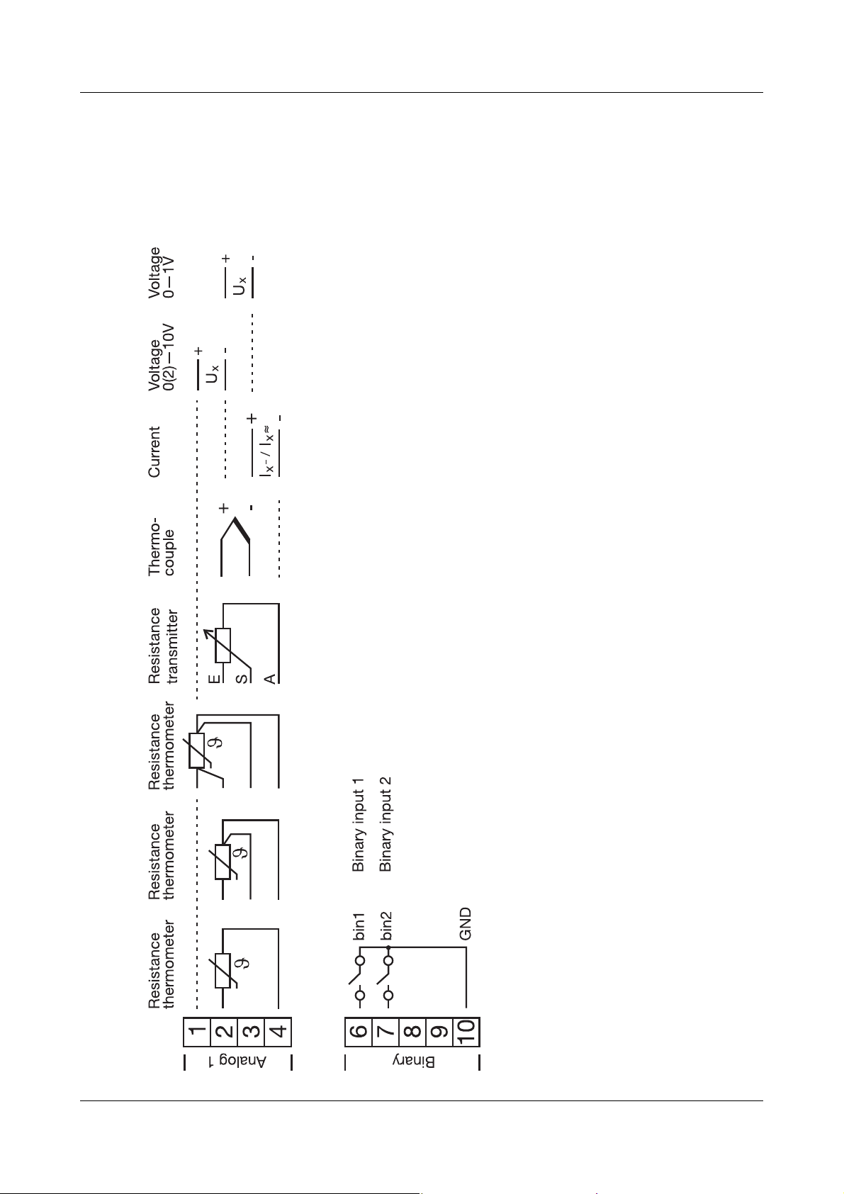
Page 19
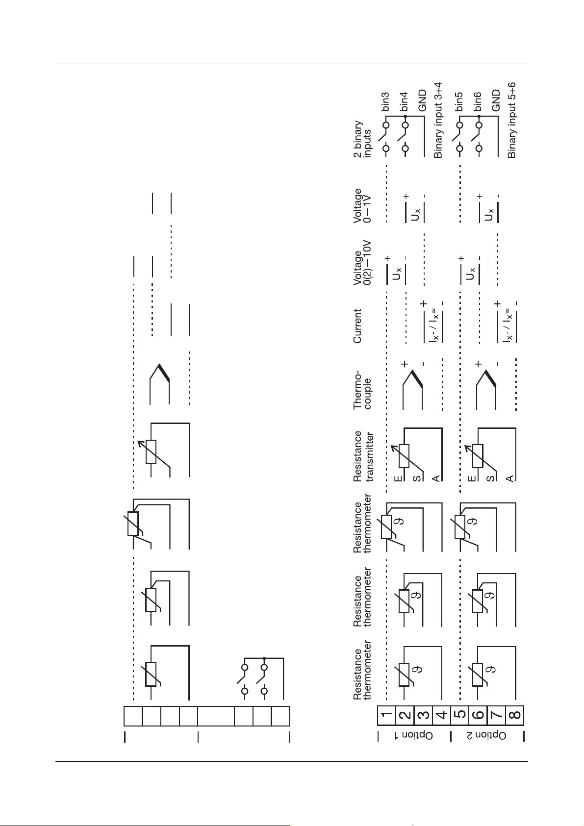
Voltage
0—1V
Voltage
0(2)—10V
Current
4 Electrical connection
-
+
x
U
-
+
x
U
-
+
~
~
x
I
- /
x
I
Thermo-
couple
Resistance
transmitter
E
Resistance
thermometer
Resistance
thermometer
-
+
As an alternative to binary outputs 3 and 4
S
A
(configurable)!
Binary input 1
Binary input 2
bin2
bin1
GND
Resistance
thermometer
1
243
Analog 1
Type 703041 continued
Analog input 1 and binary inputs 1+2 - terminal strip 2
6
Logic
7
8
Analog input 2 and binary inputs 3...6 - terminal strip 1 (option boards)
19
Page 20
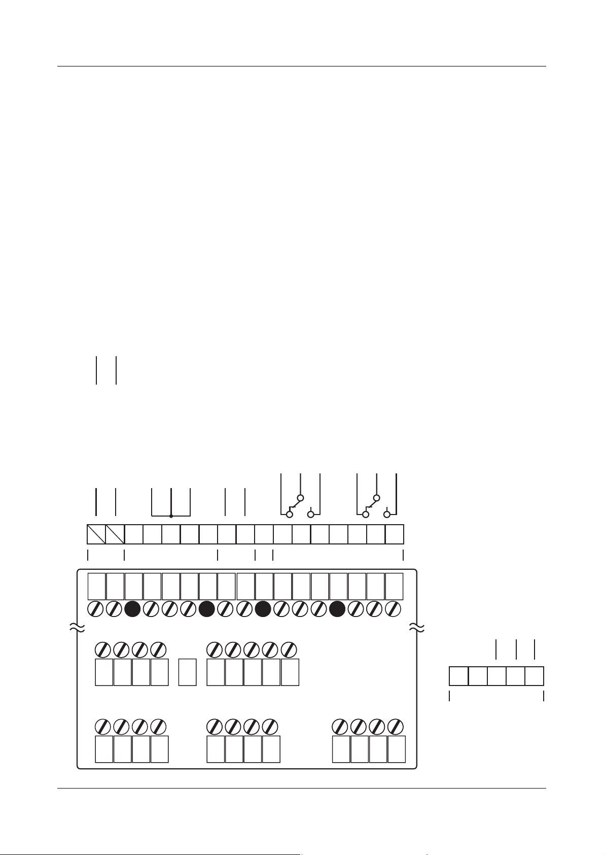
4 Electrical connection
4.3.2 Type 703042/43/44
L-
L+
Supply and outputs - terminal strip 3
2
3
110—240V AC 20—30V AC/DC
L1
L1L+N
L1(L+)
1
N
L-
Supply
N(L+)
2
Supply for 2-wire transmitter
(off-load voltage approx. 25V)
17V/20mA
+
-
=
U
5
4
4
3
4
6
5
6
6
8
=
8
9
U
9
7
8
Binary output 1 (Out1)
230V/3A
Ö
P
S
13
12
11
11
12
13
9
10
Binary output 2 (Out2)
230V/3A
Ö
P
S
16
16
17
17
15
Relays
15
Outputs - terminal strip 2
6
Logic output level 12V or 18V
(see type code)
Binary output 3
Binary output 4
Out3 (+)
Out4 (+)
GND (-)
7
8
9
10
Logic
20
1
1
2
3
4
5
6
7
8
9
10
11
12
Page 21
RS485
PROFIBUS RS422
RxD/TxD +
RxD +
RxD -
TxD +
VP (+5 V)
RxD/TxD-P (B)
RxD/TxD-N (A)
RxD/TxD -
TxD -
DGND
RxD +
VP (+5 V)
RxD/TxD +
RxD/TxD -
RxD -
TxD +
TxD -
RxD/TxD-P (B)
RxD/TxD-N (A)
DGND
4 Electrical connection
RxD/TxD +
RxD/TxD -
RxD +
RxD -
TxD +
TxD -
VP (+5 V)
RxD/TxD-P (B)
RxD/TxD-N (A)
DGND
Solid-state
relay
Out5
2 relays
(n.o. make)
Ö
Relay
(changeover)
Analog
output
Binary output 6
Binary output 5
(Out5)
Out8
Binary output 5+8
(Out5+Out8)
P
S
Binary output 5
(Out5)
-
+
x
/ I
x
U
Analog output 5
(Out5)
Out6
Ö
P
+
x
/ I
x
U
(Out6)
Out9
Binary output 6+9
(Out6+Out9)
S
Binary output 6
(Out6)
-
Analog output 6
(Out6)
Out7
Ö
P
+
Binary output 7
(Out7)
Out0
Binary output 7+10
(Out7+Out0)
S
Binary output 7
(Out7)
-
x
/ I
x
U
Analog output 7
(Out7)
Note numbering of outputs.
1
243
ype 703042/43/44 continued
Outputs and interfaces - terminal strip 1 (option boards)
Option 1
5
687
Option 2
9
101211
Option 3
H
v Chapter 8.5 “Outputs “OutP””
21
Page 22
4 Electrical connection
22
Type 703042/43/44 continued
Analog input 1 and binary inputs 1+2 - terminal strip 2
Page 23
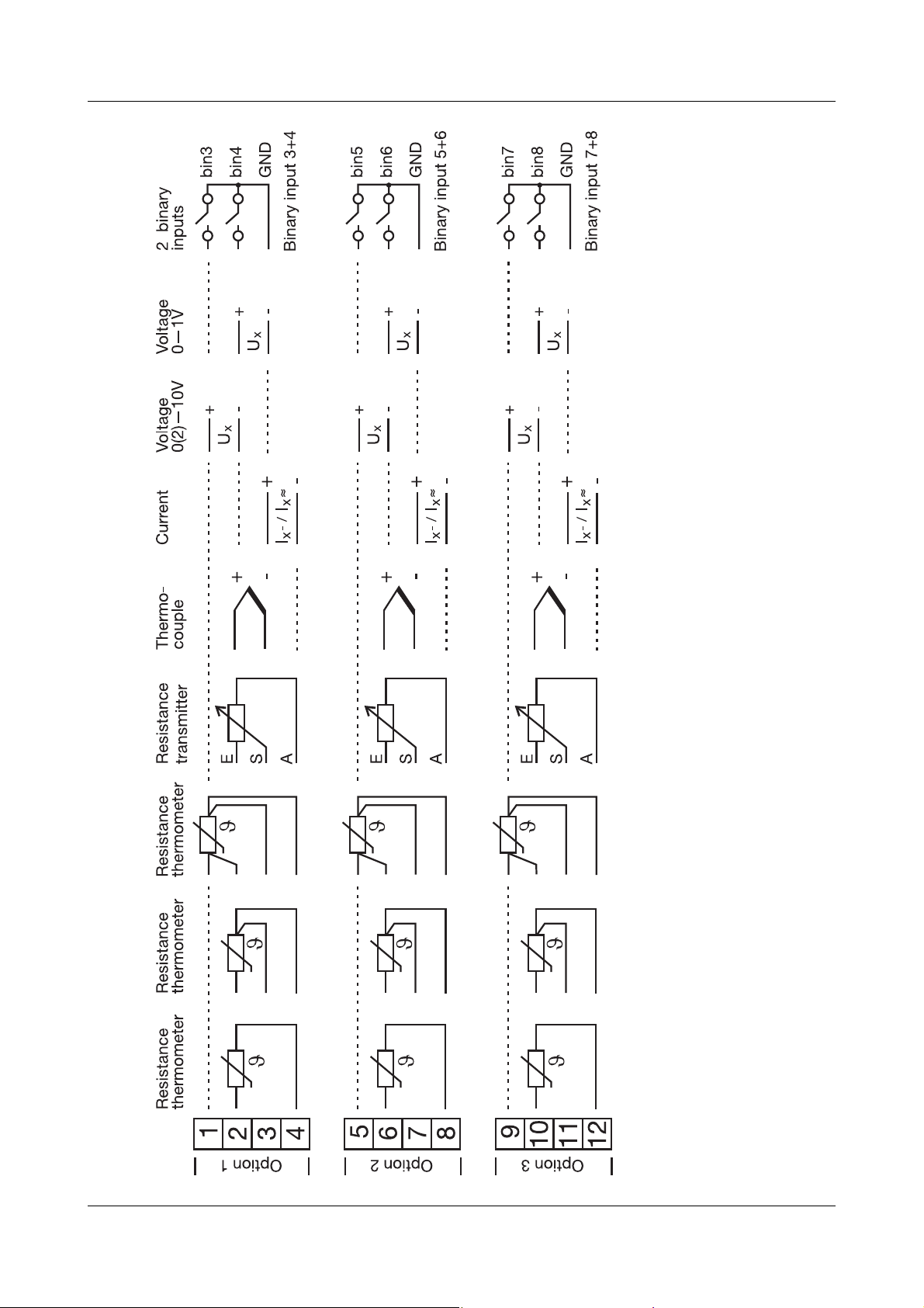
4 Electrical connection
Analog input 2 and binary inputs 3...8 - terminal strip 1 (option boards)
Type 703042/43/44 continued
23
Page 24
4 Electrical connection
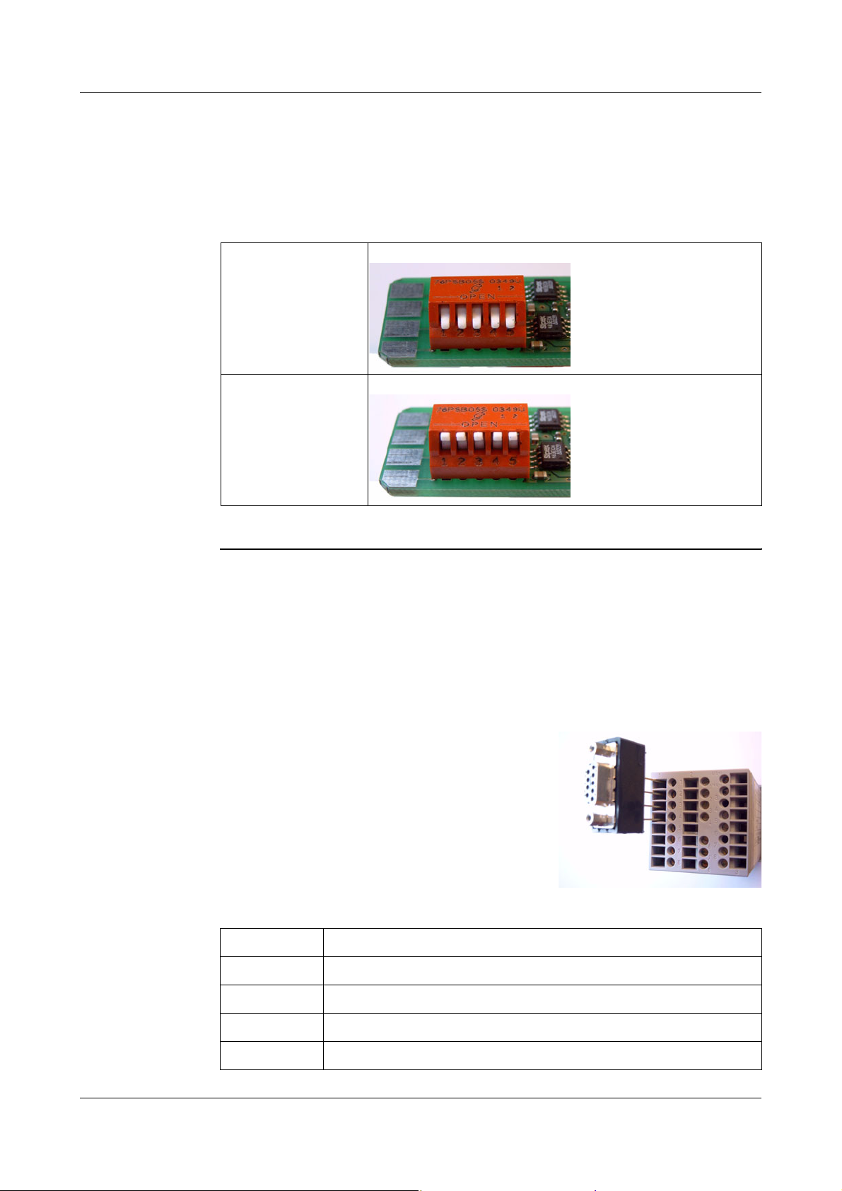
4.3.3 Termination resistor for the RS422/485 serial interface
For fault-free operation of several devices in a line structure, their internal termination
resistors must be activated at the start and end
h Pull plug-in module out towards the front by pressing on the knurled areas
h Using a ballpoint pen, press all the white switches into the same direction
.
Bus termination
resistor active:
No bus termination
(ex-factory)
h Re-insert the module back into the housing
Check h Press the
To the right of the green “VErS” display, “ON” is shown for active and “OFF“ for inactive termination resistors.
h Push all 5 switches down
h Push all 5 switches up
P + I keys
4.3.4 Connection of the PROFIBUS-DP connector
Mounting the
adapter
Assignment of
the 9-pole
D-SUB socket
h Identify option slot with the PROFIBUS-DP interface by means of the
type code (in the case of pre-configured devices)
In this example, the PROFIBUS-DP
interface is in option slot 1
H
Pin: Signal Designation
1: VP Supply voltage positive
2: RxD/TxD-P Receive/Transmit data positive
3: RxD/TxD-N Receive/Transmit data negative
4: DGND Ground
To fit the D-SUB adapter, open the housing
of the adapter; otherwise the terminal
screws are hided by the adapter.
24
Page 25

5.1 Displays and controls
(1)
5 Operation
(2)
(3)
(4)
(1) 7-segment display (factory setting: process value)
four-digit, red, decimal place is configurable
(automatic adjustment on display overflow)
(2) Active setpoint (factory setting: SP1)
SP1, SP2, SP3, SP4 (SP=setpoint); green;
(3) 7-segment display (factory setting: setpoint)
four-digit, green; decimal place is configurable;
also used for operator prompting (display of parameter and level symbols)
(4) Keys
(5) Indication
yellow, for
- switch status of binary outputs 1 —6 (display lights up = on)
- ramp/program function is active
PGM
EXIT
(6)
(5)
- manual operation is active
(6) 16-segment display for the unit °C/°F and text
two-digit, green; configurable; symbols for h, min, %
In addition, the current segment number (program), the parameter set or any
two-place letter/number combination can be displayed through the setup
program.
The displays are configurable.
v Chapter 8.7 “Display “diSP””
25
Page 26

5 Operation
5.2 Level concept
The parameters for making the settings on the instrument are arranged at different
levels.
Time-out
H
v Chapter 6 “Operator level”
v Chapter 7 “Parameter level”
v Chapter 8 “Configuration”
v Setup/Display - Operation/Time-out
User data “USEr” The setup program can be used to display and edit up to 8 freely chosen parameters
at this level.
v Setup / Configuration level / Display - Operation/ User data
The user can assign a symbol for the representation of each parameter. Otherwise the
default symbol will be used. Permissible symbols are the letters and numbers that can
be presented by a 7-segment display.
If no key is pressed for 180sec, the instrument returns to normal display.
26
Page 27

5.3 Level inhibit
The access to the individual levels can be prevented.
Code Operator level,
0 enabled enabled enabled
1 enabled enabled inhibited
2 enabled inhibited inhibited
3 inhibited inhibited inhibited
5 Operation
Parameter level Configuration level
user level,
program editor
h Go to code entry with
h Alter code with
h Enter code with
h Return to normal display with
The parameter and configuration levels can also be inhibited via the binary function.
v Chapter 8.6 “Binary functions “binF””
P (display blinks!)
P and D (simultaneously for >5sec).
I and D. Ex-factory: all levels enabled.
X or automatically after approx. 180sec
27
Page 28

5 Operation
5.4 Entries and operator prompting
Entering values When entries are made within the levels, the parameter symbol is shown in the lower
display.
Select parameter
Alter parameter
P
ID/
h Select parameter with
I or D
I I I I I I I I I I I I I
I
I
I
I
I
I
I
I
I
IIIIIIIIIIII
I
I
h Change to entry mode with P (lower display blinks!)
h Alter value with
I and D
The value alters dynamically with the duration of the key stroke.
h Accept the setting with
P, or automatically after 2sec
or
h Cancel entry with
X.
The value is not accepted.
Entering times When entering times (e.g. timer time), the time unit is shown in addition.
Select parameter
Alter parameter
I
I
I
I
I
I
D
I
I
P
ID/
I I I I I I I I I I I I I
I
I
I
I
I
I
I
I
IIIIIIIIIIII
I
I
I
I
I
I
I
I
I
I
D
I
28
The highest time unit of the display is shown for the unit.
If, for instance, “h” is shown for the hour, then the time format for the value is hh:mm.
h Select parameter with
I or D
h Change over to the entry mode using P (lower display blinks!)
h Alter value with
I and D
The value alters dynamically with the duration of the key stroke.
h Accept the setting with
P or automatically after 2sec
or
h Cancel entry with
X.
The value is not accepted.
Page 29

5.5 Fixed-setpoint controller (ex-factory)
5 Operation
Normal display
Altering the
setpoint
Manual mode In manual mode, the controller output can be altered by hand.
In normal display:
h Alter the present setpoint with
(the value is accepted automatically)
h Change to manual mode with
The output appears in the lower display. The hand symbol and the unit “%” light up in
addition.
h Alter the output with
In the case of a modulating controller, the actuator is opened or closed using the keys.
The various levels can be accessed from the manual mode.
h Finish manual mode with
The output entry on a changeover is configurable. The manual mode can be inhibited.
v Chapter 8.2 “Controller “Cntr””
I and D
Manual mode
I and D
X (> 2 sec)
X (>2 sec)
Additional operating options for the fixed-setpoint controller can be implemented via
the binary functions.
v Chapter 8.6 “Binary functions “binF””
On overrange/underrange and probe break, the controller automatically changes over
to manual mode.
29
Page 30

5 Operation
5.6 Program controller
Condition as
delivered
The instrument must be configured as a program controller/generator. Furthermore, a
program must be entered beforehand, to operate the instrument as a program
controller/generator.
5.6.1 Entering programs
Function A setpoint profile can be implemented with a maximum of 8 program segments.
Entry on the
instrument
The instrument must be configured as a program controller/generator.
v Chapter 8.3 “Generator “Pro”” (Function)
Configurable time base: mm:ss, hh:mm und dd:hh (s=seconds, m=minutes, h=hours,
d=days).
v Chapter 8.3 “Generator “Pro”” (unit)
The settings for segment setpoints (SPP1 — SPP8) and segment times (tP1 — tP8)
are made in the program editor.
30
Page 31

5 Operation
The program segments (up to eight) are defined by the segment setpoint and the segment time.
P
D
D
D
P
P
P
I I I I I I I I I I I I I
I
I
I
I
I
I
I
I
I
I I I I I I I I I I I I I
I
I
I
I
I
I
I
I
IIIIIIIIIIII
I
I I I I I I I I I I I I I
I
I
I
I
I
I
I
I
I
IIIIIIIIIIII
IIIIIIIIIIII
I
I
I
I
I
I
D
I
I
I
I
I
I
I
I
I
I
I
D
I
I
I
I
I
I
I
I
I
I
D
I
I
I
Entry through
setup program
Additional
functions via the
setup program
P
I
I I I I I I I I I I I I I
I
I
I
I
I
I
I
I
I
The setup program (accessory) features a user-friendly program editor, with a
graphical presentation of the program profile.
- Start at the process value
- Response to over/underrange
- Repeat program
- Setpoint input (ramp/step)
- Process is controlled to the most recent setpoint
- Delay time
- Program editor/management with graphical preview
- Up to four control contacts can be programmed segment by segment
- Parameter sets can be assigned segment by segment
IIIIIIIIIIII
I
I
I
I
I
I
D
I
I
I
31
Page 32

5 Operation
5.6.2 Operation
Normal display
Altering the setpoint
Normal display No program run in normal display, the controller controls to the selected setpoint.
Altering the
setpoint
From normal display:
h Change to setpoint input with
h Alter the present setpoint with I and D
(the value is accepted automatically)
Program is running
Program pause
D
Starting the
program
Canceling the
program
Pausing the
program
From normal display:
h Start program with
(the ramp symbol lights up!)
A delay time can be configured through the setup program. When the delay time has
elapsed, “
When the program is running:
h Cancel program with
When the program is running:
h Pause program with
(the lower display blinks!)
h Continue with
The program is canceled in the event of a power failure.
Additional program control functions via binary functions.
v Chapter 8.6 “Binary functions “binF””
Strt” is shown in the lower display, and then the program is processed.
I
I
X (>2 sec)
X (>2 sec)
32
Page 33

5.6.3 Shifting the program profile
The function “External setpoint with correction” can be used to shift the program
profile upwards or downwards (configurable through the setup program only).
The external setpoint is defined via an analog signal.
v Chapter 8.2 “Controller “Cntr””
5 Operation
33
Page 34

5 Operation
34
Page 35

Access
6 Operator level
The four setpoints are displayed and edited here, and additional process variables are
shown in accordance with the configuration.
Symbol Meaning
SP 1
SP 2
SP 3
SP 4
SPr
InP1
InP2
F1
F2
y
trun
trES
t1
t2
Setpoint 1 (editable)
Setpoint 2 (editable)
Setpoint 3 (editable)
Setpoint 4 (editable)
Ramp setpoint (only if configured)
Measurement of analog input 1
Measurement of analog input 2 (only if available)
Calculated result of math formula 1
(and for difference, ratio and humidity controller)
Calculated result of math formula 2 (only if available)
Controller output
Program run time (only with program controller/generator)
Residual program time (only with program controller/generator)
Timer run time 1 (only if configured)
Timer run time 2 (only if configured)
35
Page 36

6 Operator level
Definition of the program times
w
(2)(1)
(4)
(3)
tx
t
(1) Program run time (3) Segment run time
(2) Residual program time (4) Residual segment time
36
Page 37

7 Parameter level
General Two parameter sets (PAr1 and PAr2) can be stored.
Access
The level can be inhibited.
Applications - Parameter set switching via binary function
v Chapter 8.6 “Binary functions “binF””
- Allocating parameter sets to program segments (only through the setup program)
v Program editor/Program
Example Setting a 2-state controller with PI action:
Pb1=12°C (proportional band)
rt=160sec (reset time; I component)
dt=0sec (derivative time, D component)
37
Page 38

7 Parameter level
PArA ➔ PAr1 ( PAr2)
Display Value range Factory
Proportional
band
Derivative time
Reset time
Cycle time
Contact
spacing
(dead band)
Switching
differential
PB 1
Pb 2
dt
rt
CY1
CY2
db
HyS1
HyS2
0…9999 0 Size of the proportional band
0…9999 0
0…9999 s 80 s Influences the differential component of
0…9999 s 350 s Influences the integral component of the
0.0…999.9s 20 s With a switched output, the cycle time
0.0…999.9 s 20 s
0.0…999.9 0 The spacing between the two control
0.0…999.9 1 Hysteresis for switching controllers
0.0…999.9 1
Description
setting
The gain of the controller decreases with
increasing proportional band.
With Pb 1,2 = 0 the controller structure is
ineffective (limit comparator response).
Continuous controllers: Pb1,2 must be >0.
the controller output signal.
The effect of the D component increases
with increasing derivative time.
controller output signal.
The effect of the I component decreases
with increasing reset time.
should be chosen so that a) the pulsed
energy flow to the process does not cause
any impermissible PV fluctuations and b)
the switching elements are not overloaded.
contacts for 3-state or modulating
controllers.
with Pb1,2 = 0.
Actuator time
Working point
Output limiting
38
tt
Y0
Y1
Y2
The parameters Pb2, Cy2, HyS2 refer to the second controller output for a 3-state
controller.
The decimal place of some parameters depends on the decimal place setting in the
displays.
H
5…3000 s 60 s Actuator time range used by the control
valve for modulating controllers.
-100…+100% 0% Output for P and PD controllers
(when x = w then y = Y0).
0…100% 100% Maximum output limiting.
-100…+100 % -100% Minimum output limiting.
(only effective with PB>0!)
The parameter display on the instrument depends on the controller type
selected.
v Chapter 8.2 “Controller “Cntr””
Page 39

8 Configuration
General The following applies to the representation of parameters and functions at the
configuration level:
The parameter is not displayed or can not be selected if
- the equipment level does not permit the function assigned to the parameter.
Example: Analog output 2 can not be configured if
analog output 2 is not implemented in the instrument.
Access
H
Some parameters can only be programmed through the setup program. These
are marked in the symbol column with “(setup)”.
The symbol (appears in the display) that corresponds to the menu item is
shown in the chapter headings (e.g. 8.1 Analog inputs “InP”).
H
Levels can be inhibited.
v Chapter 5.3 “Level inhibit”
39
Page 40

8 Configuration
Analog selector With some parameters, you can choose from a series of analog values. To provide you
with an overview, this selection is listed below.
0 no function 21 program run time in sec
1 analog input 1 22 residual program time in sec
2 analog input 2 23 segment run time in sec
3 process value 24 residual segment time in sec
4 present setpoint 25 timer run time for timer 1 in sec
5 ramp end value 26 timer run time for timer 2 in sec
6 program setpoint 27 residual run time for timer 1 in sec
7 math 1 28 residual run time for timer 2 in sec
8 math 2 29 present segment end value
9 setpoint 1 30 analog marker (Profibus)
10 setpoint 2 31 reserved
13 controller output level 32 reserved
14 controller output 1 33 reserved
15 controller output 2
Definition of the program times
w
(2)(1)
(4)
(3)
t
x
t
(1) Program run time (3) Segment run time
(2) Residual program time (4) Residual segment time
40
Page 41

8.1 Analog inputs “InP”
8 Configuration
Configuration
Analog inputs
Controller
Generator
Limit comparators
Outputs
Binary functions
Display
Timer
Interfaces
Sensor type
InP: Analog input
Depending on the instrument version, up to two analog inputs are available.
H
The approval according to DIN EN 14597 requires the usage of probes, also
approved to DIN EN 14597, in the specified temperature ranges.
v see data sheets T90.1006 and T90.2006
Analog input 1 InP1 ➔
Analog input 2
Symbol Value/selection Description
SEnS
InP2 ➔
0
no function
1
Resistance thermometer in 3-wire circuit
2
Resistance thermometer in 2-wire circuit
3
Resistance thermometer in 4-wire circuit
4
Thermocouple
5
Resistance transmitter
6
Heater current 0— 50mA AC (analog input 2 only)
7
0—20mA
8
4—20mA
9
0—10V
10
2—10V
11
0—1V
Linearization
Lin
factory-set on analog input 2: no function
0
Linear
1
Pt100
2
Pt500
3
Pt1000
4
KTY11-6
5
W5Re_W26Re C
6
W3Re_W25Re D
7
NiCr-Con E
8
Cu-Con T
9
Fe-Con J
10
Cu-Con U
11
Fe-Con L
12
NiCr-Ni K
13
Pt10Rh-Pt S
14
Pt13Rh-Pt R
15
Pt30Rh-Pt6Rh B
16
NiCrSi-NiSi N
17
W3Re_W26Re
18
customized linearization
For customized linearization, a maximum of 10 knee-points
can be implemented, or a 5th order polynomial function
programmed (only through the setup program).
For the linearization “KTY11-6”, the resistance is 2kΩ at 25 °C
(only through the setup program).
Factory settings are shown bold.
41
Page 42

8 Configuration
Analog input 1 InP1 ➔
Analog input 2 InP2 ➔
Symbol Value/selection Description
Measurement offset
Display start
Display end
OFFS
SCL
SCH
-1999… 0… +9999 The measurement offset is used to correct a measured value
-1999…0…+9999 On transducers with standard signal and on potentiometers, a
-1999…
100
…+9999
by a certain amount upwards or downwards.
Examples:
Measured Displayed
value offset value
294.7 +0.3 295.0
295.3 - 0.3 295.0
The controller uses the corrected value (= displayed
value) for its calculation. This value is not the same as
the actually measured value. If incorrectly applied, this
A
can result in impermissible values of the control
variable.
Special case: 2-wire circuit
If the input is connected to a resistance thermometer in 2-wire
circuit, then the lead resistance is set in ohms here.
display value is assigned to the physical signal.
Example: 0 — 20mA 0 — 1500°C.
Filter time constant
Fine tuning
start value
Fine tuning
end value
Heater current
monitoring (output)
KTY correction value
at 25°C
The range of the physical signal can be 20 % wider or
narrower without generating an out-of-range signal.
dF
FtS
FtE
HEAt
(setup) 0
1. Both parameters can be activated/deactivated with setup program.
0…0.6…100 s To adjust the digital input filter (0sec = filter off).
1
-1999… 0…+9999 v See “Customized fine tuning” on Page 43.
1
-1999…1…+9999
…
2000…4000 Ω Resistance at 25°C/77°F for linearization “KTY 11-6”
Factory settings are shown bold.
63% of the alterations are acquired after 2x filter time constant
at a signal step change.
When the filter time constant is large:
- high damping of disturbance signals
- slow reaction of the process value display
to process value changes
- low limit-frequency (2nd order low-pass filter)
If these values are altered by mistake, then this setting
has to be canceled, using the procedure described
under “Customized fine tuning”.
A
These values can not be accepted by another
instrument.
0
No function
1…10
Binary output 1—10 (controller output)
The heater current is measured via a current transformer with
standard signal output and can be monitored by linking analog
output 2 to limit comparator 1.
The input signal range is 0 — 50mA AC (see probe type:
“Heater current”) and must be scaled correspondingly (display
start/end).
The heater current is measured when the heating contact is
closed. For this purpose, the binary output which controls the
heating contact (not the binary output for the alarm) has to be
selected here.
42
Page 43

Analog inputs (general)In12 ➔
Symbol Value/selection Description
Temperature unit
Sampling cycle time
Supply frequency (setup) 50Hz
Unit
CycL
60Hz
Factory settings are shown bold.
8.1.1 Customized fine tuning
8 Configuration
01deg. Celsius
deg. Fahrenheit
Unit for temperature values
0
50msec
1
90msec
2
150msec
3
250msec
Adaptation of the conversion time of the input circuitry to the
supply frequency
Activate FtS and
FtE with setup
program
Ex-factory, both parameters are not visible at the device and have to be activated first.
h Connect the device to the PC and start the setup program
h Establisch a connection to the device
h Make a double click on Undocumented parameters
h Click on check box at Parameter 17 (a tick shall appear)
h Save the setup file and execute Data transfer to device
Now the parameters FtS and FtE are visible in the Configuration level.
Principle The customised fine tuning (= fine adjustment) is used to correct the values displayed
by the device. This may be necessary, for example, after a system validation, if the
displayed values no longer coincide with the actual values at the point where the
measurement is taken.
Using a reference measuring instrument, two measured values are determined which
should be as far apart as possible (start value, end value). Ensure that the measuring
conditions are stable. Enter the reference value found as the start value (FtS) or end
value (FtE) on the device to be adjusted.
43
Page 44

8 Configuration
Caution:
A
Example The temperature inside an oven is measured with a resistance thermometer and
If start value and/or end value deviate from the factory-set values (FtS=0 and FtE=1), a
fine adjustment has already been done before. In this case the fine adjustment has to
be reset (see below).
Repeating fine adjustment without doing a reset before means that an already adjusted characteristic curve is used. This leads to wrong values.
displayed on a device. The reading on the device deviates from the actual temperature
as a result of the sensor temperature drifting. At 20°C the device reads 15°C, at 80°C
it shows 70°C (exaggerated example for better understanding).
Sensor
15°C / 70°C
Display on the device
20°C / 80°C
Actual temperature at
20°C / 80°C
reference measuring instrument
(e. g. thermometer)
Oven
Procedure h Determine lower measurement value (as low as possible and constant) with a refe-
rence measuring instrument;
Example: Oven temperature 20°C (= room temperature)
h Set start value at the device to this lower measurement value;
Example: Set start value (FtS) to 20
h Increase temperature and determine higher measurement value (as high as posible
and constant) with reference measuring instrument;
Example: Increase oven temperature to 80°C
h Set end value at the device to this higher measurement value;
Example: Set end value (FtE) to 80
Characteristic
curve
The following diagram shows the changes in the characteristic curve caused by the
fine adjustment (point of intersection with the x axis as well as ascent)
Special case: Offset
If the deviation between measured value
and displayed value at the low and high
measuring point is identical, an offset cor-
80
70
Display
(Instrument)
rection is sufficient (ascent remains
After fine
adjustment
Before fine
adjustment
unchanged). In this case, fine adjustment
is not required.
v Chapter 8.1 “Analog inputs “InP””
Parameter OFFS
20
15
Measurement
(Reference)
20 80
Reset
fine adjustment
44
In order to reset fine adjustment, the same value hast to be given to start value (FtS)
and end value (FtE) (e. g. set both parameters to 0). This automatically sets the start
value to 0 and the end value to 1 (factory setting).
Page 45

8.2 Controller “Cntr”
8 Configuration
Configuration
Analog inputs
Controller
Generator
Limit comparators
Outputs
Binary functions
Display
Timer
Interfaces
Controller type
Control action
Cntr: Controller
The following are set here: controller type, input variables of the controller, the setpoint
limits, conditions for manual mode and the presettings for autotuning (selfoptimization).
Symbol Value/selection Description
Configuration
0
CtyP
CAct
no function
1
2-state controller
2
3-state controller
3
Modulating controller
4
Continuous controller
01Direct
Inverse
Inhibit manual mode
Manual output
Range output
Setpoint low
Setpoint high
InHA
HAnd
rOut
SPL
SPH
inverse:
The controller output Y is > 0 when the process value is
smaller than the setpoint (e. g. heating).
direct:
The controller output Y is > 0 when the process value is larger
than the setpoint (e. g. cooling).
01enabled
inhibited
If the manual mode is inhibited, changing over to “manual” is
not possible from the keys or via the binary input.
-100…101 Defines the controller output level after changing over to
-100…0…101 Output on over/underrange.
-1999…+9999 Setpoint limiting prevents the input of values outside the
-1999…+9999
manual mode.
101 = last output
For modulating controller:
101 = actuator is stationary;
0 = actuator closes; 100 = actuator opens
101 = last output
For modulating controller:
101 = actuator is stationary;
0 = actuator closes; 100 = actuator opens
defined range.
H
The setpoint limits are not effective with setpoint input
via the interface.
The correction value is limited for external setpoint with
correction.
Factory settings are shown bold.
45
Page 46

8 Configuration
Symbol Value/selection Description
Inputs
Controller process
value
External setpoint
Output feedback
Method of tuning
Inhibit tuning
Output of tuning 1
Output of tuning 2
Controller standby
output
Step size
CPr
ESP
FEEd
Autotuning
tyPt
InHt
Ott1
Ott2
SOut
StSI
(analog selector)
Analog inp. 1
(analog selector)
switched off
(analog selector)
switched off
-100…0…+100% Initial output with step response
10…30…100% Step size with step response
Factory settings are shown bold.
Defines the source for the process value of the control
channel.
Activates the external setpoint input and defines the source
for the external setpoint.
External setpoint with correction:
External setpoint + setpoint 1 = present setpoint
The external setpoint is corrected up or down from the keypad
(setpoint 1). The display shows the present setpoint.
Defines the source for output feedback for a modulating
controller.
v See “Analog selector” on Page 40.
01Oscillation method
Step response method
v Chapter 9.1 “Autotuning (self-optimization)”
01enabled
inhibited
If autotuning is inhibited, it can not be started via the keys or
the binary function.
0
Relay
1
Solid-state + logic
2
Continuous
The type of the physical output for the signal of the controller
outputs 1 and 2 has to be defined.
Analog selector
46
0 no function 21 program run time in sec
1 analog input 1 22 residual program time in sec
2 analog input 2 23 segment run time in sec
3 process value 24 residual segment time in sec
4 present setpoint 25 timer run time for timer 1 in sec
5 ramp end value 26 timer run time for timer 2 in sec
6 program setpoint 27 residual run time for timer 1 in sec
7 math 1 28 residual run time for timer 2 in sec
8 math 2 29 present segment end value
9 setpoint 1 30 analog marker (Profibus)
10 setpoint 2 31 reserved
11 setpoint 3 32 reserved
12 setpoint 4 33 reserved
13 controller output level
14 controller output 1
15 controller output 2
Page 47

8.3 Generator “Pro”
8 Configuration
Configuration
Analog inputs
Controller
Generator
Limit comparators
Outputs
Binary functions
Display
Timer
Interfaces
Function
Pro: (Program) Generator
The basic function of the instrument is defined here. The instrument can be operated
as a fixed-setpoint controller with or without a ramp function, or warm-up ramp for
hot-channel equipment, program controller or program generator.
Symbol Value/selection Description
General
0
Fnct
Fixed-setpoint controller
1
Ramp function
2
Program controller
3
Program generator
4
Hot-channel controller
Ramp function:
A rising or a falling ramp function can be implemented. The
ramp end value is determined by the setpoint input and can be
altered from the I and D keys, just as for a fixed-setpoint
controller.
The ramp function can be paused or canceled via the binary
functions.
v Chapter 8.6 “Binary functions “binF””
H
Factory settings are shown bold.
The ramp function is interrupted on a probe break, or
for manual mode. The outputs react as for overrange/
underrange (configurable).
Program generator:
Is used, for instance, to output the setpoint profile via a
continuous output without a control function.
Settings for the program generator are not evaluated with
regard to the process value (e. g. start at process value,
continue, tolerance band).
47
Page 48

8 Configuration
Symbol Value/selection Description
Unit of slope
Ramp slope
Tolerance band
Unit
rASL
toLP
Ramp function Program
0
°C/min mm:ss
1
°C/hour hh:mm
2
°C/day dd:hh
s=seconds; m=minutes; h=hours;d=days
Unit of ramp slope in °C per time unit, or format of segment
times for program controller/generator.
0…9999 Value of slope for ramp function
0…999 0=off
For a program controller/generator and ramp function, the
process value can be monitored by applying a tolerance band
around the setpoint profile.
If the upper or lower limit is infringed, a tolerance limit signal is
generated, which is internally processed or produced via an
output.
Example:
Signal is produced
when process value is
20 °C larger or smaller
than
setpoint.
toLP=40
Processing the tolerance limit signal, see:
v Chapter 8.5 “Outputs “OutP””
v Chapter 8.6 “Binary functions “binF””
Program
Program start (setup) Program start
Range response (setup) Continue
Response to
power-on
Program repeat (setup) none
Setpoint input (setup) Ramp
Control to the
most recent setpoint
Delay time (setup) 0…9999 min Delays the program start by an adjustable time.
(setup) No start
(setup) inactive
start at the process
pause program
automatic start
Defines whether the program starts with the first program
setpoint or whether the present process value is accepted as
value
the first program setpoint.
Defines the response to over/underrange
Defines whether the program starts on connecting the supply
voltage.
The “Cyclic” setting has the effect of continuously repeating
cyclic
the program.
Setpoint ramp Setpoint step
Step
w
A01
If active, the process is controlled to the most recent program
active
setpoint after the program has ended.
A02
t
Basic status
Control contacts (setup) SK1
SK2
SK3
SK4
Factory settings are shown bold.
48
Strt” is shown in the lower display.
“
The four control contacts can be activated in the basic status
(when the program is not running).
Page 49

8 Configuration
Hot-channel
controller
The warm-up ramp for hot-channel equipment is used, for example, for the gentle
operation of ceramic heater elements. Damage can be avoided by allowing moisture
to evaporate slowly from the hygroscopic heater elements during the warm-up phase
(t
— t2).
0
The present setpoint is accepted as the start value for the ramp at time t
time period t
setpoint SPP2. Within this period, the ramp setpoint is increased linearly. This is
followed by the programmable dwell time tP2 (t
controlled to the present setpoint (factory setting: setpoint 1 (SP1)).
The hot-channel function, with the settings for the ramp function and the program, is
implemented through the setup program.
Relevant settings:
— t1, the programmed ramp slope rASL is used to approach the hold
0
— t2), after which the process is
1
. Within the
0
Setup/Generator/General
- Ramp slope rASL with time unit
- Tolerance band (optional)
Setup/Generator/Program
- Configure program start to “Start at process value”
- Define response after power-on; the warm-up ramp either starts automatically
when switching on the supply voltage, or by pressing the
Setup/Parameter level/Controller parameters
- Output limiting for parameter sets 1 and 2 (optional)
Setup/Program editor/Program
- Set parameter set 2 for segment 1 (segment setpoint and time are not taken into
account)
- Configure segment 2 with segment setpoint (= hold setpoint SPP2), segment time
(= dwell time tP2) and parameter set 2
Setup/Display - Operation/ User data
- Relevant parameters can optionally be placed in the user data (operator level)
I key.
49
Page 50

8 Configuration
8.4 Limit comparators “LC”
Configuration
Analog inputs
Controller
Generator
Limit comparators
Outputs
Binary functions
Display
Timer
Interfaces
Limit comparator
functions (lk)
LC: Limit comparator
Limit comparators (threshold monitors, limit contacts) can be used to monitor an input
variable (process value for the limit comparator) against a fixed limit or another
variable (the setpoint for the limit comparator). When a limit is exceeded, a signal can
be output or an internal controller function initiated.
4 limit comparators are available.
Limit comparators can have different switching functions.
The hysteresis functions “asymmetrical, left” and “asymmetrical, right” can only be set
through the setup program. The “symmetrical” hysteresis function is used as
standard.
Hysteresis function
asymmetrical, left symmetrical asymmetrical, right
lk1
lk2
lk3
lk4
lk5
lk6
50
Page 51

8 Configuration
In the case of the limit comparator functions lk7 and lk8, the measurement that is set
is monitored with respect to a fixed value AL.
Hysteresis function
asymmetrical, left symmetrical asymmetrical, right
lk7
lk8
Limit comparator 1 LC1 ➔
LC2 ➔
0
no function
1
lk1
2
lk2
3
lk3
4
lk4
5
lk5
6
lk6
7
lk7
8
lk8
Function
Limit comparator 2
Limit comparator 3 LC3 ➔
Limit comparator 4 LC4 ➔
Symbol Value/selection Description
Fnct
Limit value
Switching differential
AL
HySt
-1999…0…+9999 Limit value to be monitored
Limit range for lk1 and lk2: 0 — 9999
0…1…9999 Switching differential
Factory settings are shown bold.
51
Page 52

8 Configuration
Action/
range response
Limit comparator 1
Limit comparator 2 LC2 ➔
Limit comparator 3 LC3 ➔
Limit comparator 4
Symbol Value/selection Description
AcrA
LC1 ➔
LC4 ➔
0
absolute/off
1
relative/off
2
absolute/on
3
relative/on
Defines the switching action of the limit comparators and the
switch status for an overrange or underrange.
Action:
Defines the switching action of the limit comparators on a
setpoint change or power-on.
absolute:
At the time of alteration, the limit comparator acts according
to its function.
relative:
The limit comparator is in the OFF status.
An alteration of the limit value or the (limit comparator)
setpoint could cause the limit comparator to switch ON. Such
a reaction will be suppressed, and this condition is maintained
until the (limit comparator) process value has moved out of
the switch-on region (gray area).
Example:
Monitoring the (controller) process value x with function lk4
Setpoint alteration w1→w2
a) Initial condition
Switch-on delay
Switch-off delay
t0n
t0FF
b) Condition at the time of the alteration
The limit comparator remains OFF, although the process value
is within the switch-on region.
c) Stabilized condition
The limit comparator again operates in accordance with its
function.
This function also prevents a limit comparator from being
triggered during the approach phase.
0…9999 Delays the switch-on edge by a definable time period
0… 9999s Delays the switch-off edge by a definable time period
Factory settings are shown bold.
52
Page 53

Limit comparator 1 LC1 ➔
Limit comparator 2 LC2 ➔
Limit comparator 3 LC3 ➔
Limit comparator 4
Symbol Value/selection Description
Acknowledgement
Pulse time
Limit comparator PV
Limit comparator SP
Hysteresis function (setup) symmetrical
AcnL
tPuL
LCPr
LCSP
0… 9999s The limit comparator is automatically reset after an adjustable
(analog selector)
process value
(analog selector)
present setpoint
asymmetrical, left
asymmetrical, right
Factory settings are shown bold.
LC4 ➔
8 Configuration
0
no acknowledgement
1
acknowledgement; only with inactive limit comparator
2
acknowledgement; always possible
For settings with acknowledgement, the limit comparator is
latching, which means it remains ON, even when the switchon condition is no longer present.
The limit comparator must be reset via the D + X keys or
binary signal.
time period.
see circuit diagrams
see circuit diagrams (only with lk1—lk6)
see circuit diagrams
v Chapter 12.2 “Alarm messages”
Analog selector
0 no function 21 program run time in sec
1 analog input 1 22 residual program time in sec
2 analog input 2 23 segment run time in sec
3 process value 24 residual segment time in sec
4 present setpoint 25 timer run time for timer 1 in sec
5 ramp end value 26 timer run time for timer 2 in sec
6 program setpoint 27 residual run time for timer 1 in sec
7 math 1 28 residual run time for timer 2 in sec
8 math 2 29 present segment end value
9 setpoint 1 30 analog marker (Profibus)
10 setpoint 2 31 reserved
11 setpoint 3 32 reserved
12 setpoint 4 33 reserved
13 controller output level
14 controller output 1
15 controller output 2
53
Page 54

8 Configuration
8.5 Outputs “OutP”
Configuration
Analog inputs
Controller
Generator
Limit comparators
Outputs
Binary functions
Display
Timer
Interfaces
Numbering of the
outputs
OutP: Outputs
Configuration of the instrument outputs are subdivided into analog outputs (OutA;
max. 2) and binary outputs (OutL; max. 9). Binary outputs are relay, solid-state relay
and logic outputs. Display and numbering of the outputs depends on the assignment
of the option slots.
The switching states of the binary outputs 1—6 are shown in the display.
Standard for all instrument versions:
(Binary) output 1 (Out1) = relay
(Binary) output 2 (Out2) = relay
(Binary) output 3 (Out3) = logic output
(Binary) output 4 (Out4) = logic output
Extended numbering for the option slots:
Slot Plug-in board with
1 analog output
Option 1 Output 5 (Out5) Output 5 (Out5) Output 5+8 (Out5/Out8)
Option 2 Output 6 (Out6) Output 6 (Out6) Output 6+9 (Out6/Out9)
Option 3 Output 7 (Out7) Output 7 (Out7) Output 7+10 (Out7/Out0)
Plug-in board with
1 binary output
(relay or solid-state
relay)
Plug-in board with
2 binary outputs
(2 relays)
Binary output 1
...
Binary output 10
Binary outputs 0utL
Symbol Value/selection Description
0
0ut1
...
0ut0
Factory settings are shown bold.
no function
1
Controller output 1 (ex-factory with Out1)
2
Controller output 2
5
Binary input 1
6
Binary input 2
7
Binary input 3
8
Binary input 4
9
Binary input 5
10
Binary input 6
11
Binary input 7
12
Binary input 8
13
Limit comparator 1
14
Limit comparator 2
15
Limit comparator 3
16
Limit comparator 4
17
Control contact 1
18
Control contact 2
19
Control contact 3
20
Control contact 4
21
Logic formula 1
22
Logic formula 2
23
Timer 1 active
24
Timer 2 active
25
Program active
26
Program end signal
27
Tolerance limit signal
28
Manual mode on/off
29
Binary marker
30
Any binary value from storage address (only through setup)
31
always active
54
Page 55

Function
Type of signal
Range output
Analog outputs 0utA ➔ Output 5 0ut5 ➔
Output 6 0ut6 ➔
Output 7 0ut7 ➔
Symbol Value/selection Description
Fnct
S iGn
r0ut
(analog selector)
switched off
0…101% Signal on going above/below range
Function of the output
Physical output signal
0
0—10V
1
2—10V
2
0—20mA
3
4—20mA
101 = last output signal
8 Configuration
H
Zero point
End value
0Pnt
End
-1999…0…+9999 A physical output signal is assigned to the value range of an
-1999…
100
…+9999
output variable.
Ex-factory, the setting corresponds to an output level of
0 — 100% for controller outputs.
No changes of the ex-factory setting are required for
continous controllers with only one output.
H
Example (function as a transducer):
An analog output (0 — 20mA) is to be used to put out the
process value (value range 150 to 500 °C), that means:
150 to 500°C
Offset (setup) -1999…0…+9999 The offset is used to correct the output signal by a certain
Factory settings are shown bold.
amount upwards or downwards.
Examples:
Original Output
value Offset value
294.7 +0.3 295.0
295.3 - 0.3 295.0
If the output is a controller output, the controller
switches over to manual mode and produces the
output level defined in chapter “Controller Cntr”
under rOut.
Chapter 8.2 “Controller “Cntr””
Setting for controller outputs for cooling
With 3-state controllers, the following settings must
be predefined:
zero: 0 / end value: -100
0 — 20mA; Zero point: 150 / End value: 500
Analog selector
0 no function 21 program run time in sec
1 analog input 1 22 residual program time in sec
2 analog input 2 23 segment run time in sec
3 process value 24 residual segment time in sec
4 present setpoint 25 timer run time for timer 1 in sec
5 ramp end value 26 timer run time for timer 2 in sec
6 program setpoint 27 residual run time for timer 1 in sec
7 math 1 28 residual run time for timer 2 in sec
8 math 2 29 present segment end value
9 setpoint 1 30 analog marker (Profibus)
10 setpoint 2 31 reserved
11 setpoint 3 32 reserved
12 setpoint 4 33 reserved
13 controller output level
14 controller output 1
15 controller output 2
55
Page 56

8 Configuration
8.6 Binary functions “binF”
Configuration
Analog inputs
Controller
Generator
Limit comparators
Outputs
Binary functions
Display
Timer
Interfaces
Switching action
binF: Binary functions
Functions are assigned here to the binary signals of the binary inputs and limit
comparators.
In addition, the functions for control contacts, tolerance limit signal and program end
signal are defined for program controllers/generators.
In the case of a fixed-setpoint controller, functions can be assigned to the ramp end
signals.
Edge-triggered
functions
State-triggered
functions
The functions are arranged in two groups:
The binary function reacts to switch-on edges.
The following functions are edge-triggered:
- Start/stop of autotuning
- Acknowledge limit comparators
- Program start/cancel
-Start timer
- Segment change
The binary function reacts to switch-on or switch-off states.
- All remaining functions
56
Page 57

Binary input 1
...
Binary input 8
Limit comparator 1
...
Limit comparator 4
Timer 1
Timer 2
Logic 1
Logic 2
Control contact 1
...
Symbol Value/selection Description
0
b in1
b in8
LC1
LC4
tF1
tF2
Lo1
Lo2
CC1
no function
1
Start autotuning
2
Cancel autotuning
3
Change to manual mode
4
Controller off (controller outputs are switched off)
5
Inhibit manual mode
6
Hold ramp
7
Cancel ramp
8
Setpoint changeover
9
Parameter set switching
10
Key inhibit
11
Level inhibit
12
Display “off” with key inhibit
13
Acknowledge limit comparators
14
Inhibit program start
15
Start program
16
Pause program
17
Cancel program
18
Segment change
19
Start timer 1
20
Start timer 2
21
Cancel timer 1
22
Cancel timer 2
8 Configuration
Control contact 4
Tolerance limit signal
Program end signal
Setpoint and
parameter set
switching
CC4
toLS
PrES
Factory settings are shown bold.
Level inhibit:
The parameter and configuration levels are inhibited.
In addition, the start of autotuning is inhibited.
Program end signal:
The signal is active after approx. 1 second (pulse). For longer
signals, the program end signal can be used to start a timer.
Text display:
If the binary function is active, a configurable text is shown in
the lower display. The text can be uniquely defined (only
through the setup program).
Type 703041:
The settings for the binary inputs 1+2 have priority over those
for the logic outputs.
A binary function can be used to switch between setpoint 1 and setpoint 2 or
parameter set 1 and parameter set 2.
Setpoint switching Parameter set switching Binary signal
Setpoint 1 active Parameter set 1 active 0/contact open
Setpoint 2 active Parameter set 2 active 1/contact closed
In order to switch between the four possible setpoints, two binary functions must be
configured to “setpoint switching”. The states of the two binary functions are
designated Z1 and Z2 and switch the setpoints over as shown in the table below:
Setpoint Z2 Z1
Setpoint 1 00
Setpoint 2 01
Setpoint 3 10
Setpoint 4 11
0 = contact open /OFF 1 = contact closed /ON
57
Page 58

8 Configuration
The states Z1 and Z2 are assigned to the
binary functions in descending order (see
list on the right), i. e. the first binary
function selected in the list is Z1.
Example:
The setpoint is to be selected via a binary
input and the state of one limit comparator.
This results in the following assignment:
Z1 - binary input 1
Z2 - limit comparator 1
The binary function for the binary input 1
and limit comparator 1 have to be
configured to “setpoint switching”
Depending on the further configuration, the
following diagram applies:
* only for program controller/generator
Additional
functions via the
setup program
58
* An exception to this is the configuration for a program controller with external setpoint input, with
or without correction. Setpoint 2 is the program setpoint in this case.
Several binary functions can be combined through the setup program. In addition, the
binary function “Text display” can be implemented. This is used to show a letter
combination in the lower display.
Page 59

8.7 Display “diSP”
8 Configuration
Configuration
Analog inputs
Controller
Generator
Limit comparators
Outputs
Binary functions
Display
Timer
Interfaces
Upper display
Lower display
Decimal point
diSP: Display
The values displayed can be matched to the existing requirements.
Furthermore, time-out and level inhibit can be configured here.
Symbol Value/selection Description
General
d iSU
d iSL
dEcP
(analog selector)
process value
(analog selector)
present setpoint
Displayed value for the upper display
Displayed value for the lower display
0
no decimal place
1
one decimal place
2
two decimal places
If the value that is be displayed can no longer be represented
with the programmed decimal point, then the number of
decimal places will be automatically reduced. If, subsequently,
the measured value decreases, the number increases to the
programmed value of the decimal point.
16-segment display
Brightness (setup) 0…5 (bright) 0—5 (dark)
Time-out (setup) 0 …180…255s Time period, after which the instrument automatically returns
Level inhibit (setup) none
diSt
configuration level
parameter/
configuration level
operator/
parameter/
configuration level
User data (setup program)
Up to eight parameters from different levels can be shown under User data (operator level) on
the instrument and edited. The symbols for these parameters (shown in the lower display)
must be assigned by the user himself.
Factory settings are shown bold.
Displayed value for the two-digit 16-segment display
0
switched off
1
Unit (°C or °F)
2
current segment
3
current parameter set
4
text (only setup program)
to normal display if no key is pressed.
The access to the individual levels can be inhibited.
The setting is independent of the binary function “level inhibit”.
Inhibiting the parameter level will, at the same time, also inhibit
the start of autotuning.
59
Page 60

8 Configuration
Analog selector 0 no function 21 program run time in sec
1 analog input 1 22 residual program time in sec
2 analog input 2 23 segment run time in sec
3 process value 24 residual segment time in sec
4 present setpoint 25 timer run time for timer 1 in sec
5 ramp end value 26 timer run time for timer 2 in sec
6 program setpoint 27 residual run time for timer 1 in sec
7 math 1 28 residual run time for timer 2 in sec
8 math 2 29 present segment end value
9 setpoint 1 30 analog marker (Profibus)
10 setpoint 2 31 reserved
11 setpoint 3 32 reserved
12 setpoint 4 33 reserved
13 controller output level
14 controller output 1
15 controller output 2
60
Page 61

8.8 Timer “tFct”
8 Configuration
Configuration
Analog inputs
Controller
Generator
Limit comparators
Outputs
Binary functions
Display
Timer
Interfaces
Function
tFct: Timer function
Time-dependent control actions can be carried out with the help of the timer. The
timer signal (timer 1+ 2) shows whether the timer is active. It can be output via the
binary outputs or processed internally.
The timers are started or canceled via the binary functions.
v Chapter 8.6 “Binary functions “binF””
The current timer run times can be viewed at the operator level (process data).
Timer 1 tF1 ➔
Timer 2 tF2 ➔
Symbol Value/selection Description
0
Fnct
no function
1
with timer running: timer signal=1 (signal is active) /
unit of time: hh:mm
2
with timer running: timer signal=0 (signal is inactive) /
unit of time: hh:mm
3
tolerance band / unit of time: hh:mm
4
with timer running: timer signal=1 (signal is active) /
unit of time: mm:ss
5
with timer running: timer signal=0 (signal is inactive) /
unit of time: mm:ss
6
tolerance band / unit of time: mm:ss
Timer setting
Tolerance limit
t
toLt
Signal active Signal inactive
Function: “Tolerance band”
The time runs when the process value has reached a tolerance
band around the setpoint.
Timer signal = 1 (signal is active) from the start of the function
until the time has expired.
0...99:59 Time input (unit of time, see “Function”)
0…999 0=off
Factory settings are shown bold.
61
Page 62

8 Configuration
8.9 Interfaces “IntF”
Configuration
Analog inputs
Controller
Generator
Limit comparators
Outputs
Binary functions
Display
Timer
Interfaces
Protocol
Device address
Analog marker
Binary marker
Configuration
IntF: Interfaces
The interface parameters for the RS422/485 or PROFIBUS-DP interface have to be
configured in order to communicate with PCs, bus systems and peripheral devices.
PROFIBUS-DP Pr0F ➔
Symbol Value/selection Description
0
Prot
Adr
AnAP
binP
0…125 …255 Address in data network
-1999…0…+9999 Analog value
0 …255 Binary value
Factory settings are shown bold.
Intel
1
Motorola
2
Intel integer
Modbus r422 ➔
Symbol Value/selection Description
Protocol
Baud rate
Data format
Device address
Min. response time (setup) 0…500ms Minimum time that elapses between the request of a device in
Prot
bdrt
dFt
Adr
H
0…1 …255 Address in data network
Factory settings are shown bold.
Interface descriptions:
- B70.3041.2.0 (Modbus)
- B70.3041.2.3 (PROFIBUS-DP)
01Modbus
Modbus integer
0
9600 bps
1
19200 bps
2
38400 bps
0
8 data bits, 1 stop bit, no parity
1
8 data bits, 1 stop bit, odd parity
2
8 data bits, 1 stop bit, even parity
3
8 data bits, 2 stop bits, no parity
the data network and the response of the controller.
62
Page 63

9.1 Autotuning (self-optimization)
9 Tuning (optimization)
Oscillation
method
Step response
method
Autotuning (self-optimization, SO) establishes the optimum controller parameters for a
PID or PI controller.
Depending on the controller type, the following controller parameters can be defined:
Reset time (rt), derivative time (dt), proportional band (Pb), cycle time (Cy), filter time
constant (dF)
The controller selects one of two procedures (a or b), depending on the size of the
control deviation:
a) SO in the approach phase
Start of SO
This type of optimization involves determining the control parameters through an
output step that is applied to the process. First a standby output is produced until the
process value is “steady” (constant). Afterwards, an output step (step size), which can
be defined by the user, is automatically applied to the process. The resulting response
of the process value is used to calculate the control parameters.
b) SO at setpoint
Start of SO
Autotuning establishes the optimum control parameters for a PID or PI controller,
according to the selected control structure.
Depending on the controller type, the following control parameters can be determined:
Reset time (rt), derivative time (dt), proportional band (Pb), cycle time (Cy), filter time
constant (dF)
Autotuning can be started from any system status, and can be repeated as often as is
required.
The controller outputs (continuous, relay, solid-state), the controller standby output
and the step size (min. 10%) have to be defined.
Principal applications of the step response method
- Autotuning instantly after “power on”, during the approach phase
Considerable time savings, setting: controller standby output = 0 %.
- The process does not readily permit oscillations (e.g. highly insulated furnaces with
small losses, long oscillation period)
- Process value must not exceed setpoint
If the output (with stabilized setpoint) is known, overshoot can be avoided through
the following adjustment:
standby output + step size <= output in stabilized condition
63
Page 64

9 Tuning (optimization)
With output type “solid-state”, the cycle time during autotuning is
H
Start of autotuning after power-on and during the approach phase
reduced to 8 x the sampling cycle time.
With the “relay” output type, care has to be taken that the process value
is not influenced by the cycle time, since otherwise autotuning can not be
completed successfully.
Solution: Reduce the cycle time Cy, until the process value is no longer
influenced. (Manual mode can be used for the adjustment!)
64
Page 65

Start of autotuning during operation
9 Tuning (optimization)
Starting autotuning
Canceling autotuning
h Start with
“tUnE” is shown, blinking, in the lower display
Autotuning is ended when the display automatically
changes over to normal display.
The duration of autotuning depends on the control
process.
H
h Cancel with
I and D (simultaneously >2sec
The type of controller outputs has to be defined for autotuning.
v Chapter 8.2 “Controller “Cntr””
For a device configured as program controller, the autotuning can only be
started if no program is running (normal display).
In case of problems, you may find further information at www.jumo.net
(Support/FAQ).
I and D (simultaneously)
I I I I I I I I I I I I I
I
I
I
I
I
I
I
I
IIIIIIIIIIII
I
I
I
I
I
I
I
I
I
I
65
Page 66

9 Tuning (optimization)
9.2 Check of the tuning
The optimum adaptation of the controller to the process can be checked by recording
the approach phase (e.g. with Startup) with the control loop closed. The diagrams
below indicate possible maladjustments and how these can be corrected.
The control response of a third-order control loop for a PID controller is shown as an
example. However, the procedure for adjusting the controller parameters can also be
applied to other control loops.
Pb too large
Pb too small
rt, dt too small
rt, dt too large
66
Cy too large
optimum
adjustment
Page 67

10 Extra codes
10.1 Math and logic module
The setup program can be used to implement two mathematical calculations or logical
combinations of various signals and process variables from the controller in a formula.
With math formulae, the calculated result is presented through the two signals
“Math 1” and “Math 2” of the analog selector. With logic formulae, the result of the
logical combination is available through the signals “Logic 1” and “Logic 2” of the
binary selector and when configuring the binary functions.
Chapter 8.6 “Binary functions “binF””
Entering formulae - The string of signs in the formula consists of ASCII characters, and can have a
maximum length of 60 characters.
- The formula can only be entered in the setup program.
- Formulae can be freely entered according to normal mathematical rules.
- Spaces can be inserted at will into the formula character string. But spaces are not
permitted within function labels, variable names and constants.
10.2 Difference, humidity or ratio controller
Difference
control
The controller is preset either as a difference/humidity or ratio controller (extra code)
or must be configured via the setup program. Analog input 2 must be available.
v Setup/Only setup/Math/Logic/Math 1
The process variables for the two analog inputs have a fixed definition.
The difference between the measurements from analog input 1 and 2 is formed and
made available via “Math 1”. Input 1 is affected by the controller. Input 2 is the reference value.
Difference: E1-E2
E1
= analog input 1
E2
=2
analog input
w
= setpoint
x
= process value
E1
E2
Math
E1 - E2
Upper
display
x
w
For the controller to function as a difference controller, further settings have to be
made:
- controller process value: math 1
v Chapter 8.2 “Controller “Cntr””
If the difference is to be displayed, then one display must be configured to “Math 1”.
v Chapter 8.7 “Display “diSP””
67
Page 68

10 Extra codes
Humidity control A psychrometric humidity sensor is used to determine relative humidity, through the
mathematical combination of wet bulb and dry bulb temperatures.
relative humidity: (E1, E2)
E1
Math
E1
E2
%
w
Upper
display
x
For the controller to function as a humidity controller, further settings have to be made:
- controller process value: math 1
v Chapter 8.2 “Controller “Cntr””
If the value for relative humidity needs to be displayed, then one display must be con-
figured to “Math 1”.
v Chapter 8.7 “Display “diSP””
= analog input 1
(dry bulb temperature)
E2
=2
analog input
(wet )
w
x
bulb temperature
= setpoint
= process value
Ratio
control
The control is always based on analog input 1 (E1).
The math module forms the ratio of the measurements from E1 and E2, and produces
the setpoint for the controller. The ratio of the measurements can be called up through
the function “Math 1” and displayed.
The required ratio E1/E2 is programmed as the setpoint (ratio setpoint) in the setpoint
definition.
Ratio: E1/E2
E1
= analog input 1
E2
=2
analog input
w
= setpoint
wv
= ratio setpoint
x
= process value
E1
E2
Math
wv
E1 / E2
wv
E2
*
Upper
display
w
x
For the controller to function as a ratio controller, further settings have to be made:
- controller process value: analog input 1
- external setpoint: ramp end value
v Chapter 8.2 “Controller “Cntr””
68
If the ratio needs to be displayed, then one display must be configured to “Math 1”.
v Chapter 8.7 “Display “diSP””
Page 69

Safety notes
A
E
11 Retrofitting of modules
Retrofitting of modules must only be carried out by qualified
professional persons.
The modules can be damaged by electrostatic discharge. So avoid
electrostatic charge during fitting and removal. Carry out retrofitting on a
workbench that is earthed.
Identifying the
module
h Identify the module by the Sales. No. glued onto the packaging
Module Code Sales no. View of boards
Analog input 2 1 70/00442785
1 relay (changeover, SPDT) 2 70/00442786
2 relays (make, SPST-NO) 3 70/00442787
1 analog output 4 70/00442788
2 binary inputs 5 70/00442789
1 solid-state relay 230V/1A 6 70/00442790
RS422/485 interface 7 70/00442782
PROFIBUS-DP 8 70/00442791
69
Page 70

11 Retrofitting of modules
Removing the
controller
module
Retrofitting of
modules
h Press together the knurled surfaces on
the front panel (top and bottom, or left
and right for landscape format) and pull
out the controller module.
h Select the slot for the option
(Observe the restrictions for Type 703041! (see connection diagram))
Type 703041
Option 1
Type 703042/43/44
Option 1
Option 2
H
h Push the module into the slot until the plug connector snaps into place
On Type 703041, relays
can only be retrofitted in
option slot 1!
Option 2
Option 3
70
h Push the module into the housing until the lugs snap into their slots
Page 71

12.1 Technical data
Thermocouple input
12 Appendix
Designation Measuring range Measuring
Fe-Con L
Fe-Con J
Cu-Con U
Cu-Con T
NiCr-Ni K
NiCr-Con E
NiCrSi-NiSi N
Pt10Rh-Pt S
Pt13Rh-Pt R
Pt30Rh-Pt6Rh B
W5Re-W26Re C
W3Re-W25Re D
W3Re-W26Re
Cold junction Pt100, internal
a. in the range 300 to 1820°C
EN 60 584
EN 60 584
EN 60 584
EN 60 584
EN 60 584
EN 60 584
EN 60 584
EN 60 584
-200 to +900°C
-200 to +1200°C
-200 to +600°C
-200 to +400°C
-200 to +1372 °C
-200 to +1000°C
-100 t o +1300°C
0 to 1768°C
0 to 1768°C
0to 1820°C
0 to 2320 °C
0 to 2495 °C
0 t o 2400 °C
accuracy
≤0.25%
≤0.25%
≤0.25%
≤0.25%
≤0.25%
≤0.25%
≤0.25%
≤0.25%
≤0.25%
≤0.25%
≤0.25%
≤0.25%
≤0.25%
a
Ambient
temperature error
100 ppm /°C
100 ppm /°C
100 ppm /°C
100 ppm /°C
100 ppm /°C
100 ppm /°C
100 ppm /°C
100 ppm /°C
100 ppm /°C
100 ppm /°C
100 ppm /°C
100 ppm /°C
100 ppm /°C
Input for resistance thermometer
Designation Connection Measuring range Measuring
accuracy
3-/4-wire 2-wire
Pt100 EN 60 751 2-wire / 3-wire / 4-wire -200 to +850°C ≤0.05% ≤0.4% 50 ppm / °C
(factory setting)
Pt500 EN 60 751 2-wire / 3-wire / 4-wire -200 to +850 °C ≤0.2% ≤0.4% 100 ppm /°C
Pt1000 EN 60 751 2-wire / 3-wire / 4-wire -200 to +850°C ≤0.1% ≤0.2% 50 ppm /°C
KTY11-6 2-wire -50 to +150°C — ≤2.0% 50 ppm /°C
Sensor lead resistance max. 30Ω per lead for 3-wire or 4-wire circuit
Measuring current approx. 250µA
Lead compensation Not required for 3-wire or 4-wire circuit. With a 2-wire circuit, the lead resistance can be
compensated in software by a correction of the process value.
Ambient
temperature error
Input for standard signals
Designation Measuring range Measuring
accuracy
Voltage 0(2) — 10 V
0—1V
input resistance R
Current 0(4) — 20mA, voltage drop ≤ 1.5V ≤0.05% 100 ppm / °C
Heating current 0 — 50mA AC ≤1% 100 ppm / °C
Resistance transmitter min. 100Ω, max. 4kΩ≤0.5% 100 ppm / °C
> 100kΩ
IN
≤0.05%
≤0.05%
Ambient
temperature error
100 ppm / °C
100 ppm / °C
Binary inputs
Floating contacts
71
Page 72

12 Appendix
Measuring circuit monitoring
In the event of a fault, the outputs move to a defined (configurable) status.
Sensor Overrange /
underrange
Thermocouple
Resistance thermometer
Voltage 2 — 10V
0 — 10V
0 — 1V
Current 4 — 20mA
0 — 20mA
Resistance transmitter
• = recognized - = not recognized
•- •
•• •
•
•
•
•
•
-- •
Outputs
Relay (changeover)
for Type 703042/43/44
contact rating
contact life
Relay (changeover) (option)
contact rating
contact life
Relay (n.o. make)
for Type 703041
contact rating
contact life
Relay (n.o. make) (option)
contact rating
contact life
Logic output 0/12V / 30mA max. (sum of all output currents) or
Solid-state relay (option)
contact rating
protection circuitry
Voltage (option)
output signals
load resistance
accuracy
Current (option)
output signals
load resistance
accuracy
Supply voltage for
2-wire transmitter
for Type 703042/43/44
voltage
a. 3 A with devices certified to DIN EN 14597
350,000 operations at rated load / 750,000 operations at 1A
100,000 operations at rated load / 350,000 operations at 3A
350,000 operations at rated load / 900,000 operations at 1A
Probe or lead short-circuit Probe or lead break
•
-
-
•
-
5A at 230 VAC resistive load
8A at 230V AC resistive load
3A at 230VAC resistive load
150,000 operations at rated load / 350,000 at 1A
3A at 230VAC resistive load
0/18V / 25mA max. (sum of all output currents)
The holding current of the triac is at least 50mA.
electrically isolated, not stabilized
17V at 20mA load, 25V DC with no load
1A at 230 V
varistor
0 — 10V / 2 — 10V
R
≥ 500Ω
load
≤0.5%
0 — 20mA / 4 — 20 mA
R
≤500Ω
load
≤0.5%
a
a
•
-
-
•
-
Controller
Controller type 2-state controller (factory setting),
3-state controller, modulating controller, continuous controller
Controller structures P/PD/PI/PID
A/D converter dynamic resolution up to 16-bit
Sampling cycle time 50msec, 90 msec, 150 msec, 250 msec (factory setting: 250 msec)
72
Page 73

12 Appendix
Electrical data
Supply voltage (switchmode PSU) 110 — 240V AC -15/+10%, 48 — 63 Hz
20— 30 V AC/DC, 48— 63Hz
Electrical safety Type 703041: to EN 61010, Part 1
Type 703042/43/44: to EN 60730
Overvoltage category III, pollution degree 2
Power consumption Type 703041: 8VA max.
Type 703042/43/44: 13VA max.
Data backup EEPROM
Electrical connection at the back, via screw terminals,
conductor cross-section up to 2.5mm
with core ferrules (length: 10 mm)
Conductor cross-sections and core-end ferrules for installation
2
Electromagnetic compatibility
interference emission
interference immunity
Minimum
crosssection
Without core-end ferrule 0.34mm
Core-end ferrule, no lip 0.25mm
Core-end ferrule, lip up to
2
1.5mm
Core-end ferrule, lip above
2
1.5mm
Twin ferrule with lip 0.25mm
0.25mm
1.5mm
EN 61326-1
to industrial requirements
2
2
2
2
2
Class B
Maximum
crosssection
2
2.5mm
2
2.5mm
2
1.5mm
2
2.5mm
2
1.5mm
Housing
Housing type plastic housing for panel mounting to IEC 61554
Depth behind panel 90 mm
Ambient/storage temperature range 0 to 55°C / -30 to +70°C
Climatic conditions rel. humidity ≤90% annual mean, no condensation
Operating position horizontal
Enclosure protection to EN 60 529, front IP65 / back IP20
Weight (fully fitted) Type 703041: approx. 220g
Type 703042/43: approx. 380g
Type 703044: approx. 490g
Min. length of
core-end ferrule
10mm
(stripped)
10mm
10mm
12mm
12mm
Interface
Modbus
Interface type RS422/485
Protocol Modbus, Modbus Integer
Baud rate 9600, 19200, 38400
Device address 0 — 255
Max. number of nodes 32
PROFIBUS-DP
Device address 0 — 255
Approvals/marks of conformity
Mark of
conformity
DIN DIN CERTCO Register No. TR1187 DIN EN 14597 all types
GL - Hardware
GL - Software
c UL us Underwriters Laboratories E 201387 UL 61010-1
Testing laboratory Certificates/certification
numbers
Germanischer Lloyd Type Approval Certificate
No. 45 059-07 HH
Test bas i s val i d f o r
GL-Approval
Category C, EMC1
CAN/CSA-C22.2 No. 61010-1
703044/191-320-23/
214, 062
all types
73
Page 74

12 Appendix
12.2 Alarm messages
Display Cause Fault removal
-1999
(blinking!)
9999
(blinking!)
9999
(lower display)
----
(blinking!)
all displays on;
lower
7-segment
display is
blinking
PrOF
OPt
Underrange for the value being
displayed.
Overrange for the value being
displayed.
Error in output feedback of
modulating controller
Source signal for controller
process value is switched off
Watchdog or power-on trigger
initialization (reset).
PROFIBUS error Can be suppressed by setting the
Hardware configuration error Check which option boards are installed in
test/repair/replace
- Check that the connected probe complies with the configured sensor type and
linearization
- Check the probe connection and the terminals
- Check the cable
- Check probe for short-circuit and probe
break
- In case of standard signal:
Is the signal within the permissible range
(e.g. 4 - 20mA)?
Check the source signal for output feedback
Select a source signal in configuration level
Replace the controller if the initialization
continues for more than 5sec
PROFIBUS address to “0” (if PROFIBUS
interface is not used).
the slots
Overrange / underrange covers the following events:
- Probe break or short-circuit
- Measurement is outside the controllable range for the probe that is connected
- Display overflow
74
Page 75

13 Index
A
Access code 39
Accessories
Acknowledgement
Analog input
Analog marker
Analog selector
Autotuning (self-optimization)
10
53
41
62
40
B
Baud rate 62
Binary functions
Binary marker
Binary output
Brightness
56
62
54
59
C
Connection diagrams 17
Control action
Control contacts
Controller
Controller module, removing
Controller standby output
Controller type
45, 61–62
48
45
46
45, 54, 57, 61
D
Data format 62
Decimal point
Delay time
Device address
Difference control
Dimensions
Display
Display end
Displays
59
48
62
67
11
59
42
25
E
Electrical isolation 16
End value
Entering formulae
Entering programs
Entering times
Entering values
55
67
30
28
28
F
Filter time constant 42
Fine tuning
Fitting
Front panel, care of
42
13
13
46, 63
14
H
Heater current monitoring 42
Hot-channel controller
Humidity control
49
68
I
Installation notes 15
Interface
62
L
Level concept 26
Level inhibit
Limit comparator
Limit comparator functions
Limit value
Linearization
27, 59
50
50
51
41
M
Manual mode 55
Manual mode, inhibiting
Manual output
Measurement offset
Module
identification
retrofitting
Mounting site
45
69
69
11
45
42
O
Outputs 54
numbering
54
P
Parameter level 37
Parameter set switching
Password
PC interface
Program profile, shifting
Program start
Protocol
Pulse time
39
10
48
62
53
57
33
R
Ramp slope 48
Range output
Ratio control
45
68
S
Safety notes 69
Sampling cycle time
43
75
Page 76

13 Index
Scope of delivery 10
Sensor type
Setpoint
external
Setpoint limits
Setpoint switching
Setup program
Side-by-side mounting
Signal type
Step response method
Step size
Supply frequency
Switching action
Switching differential
Switch-on delay
41
35
46
45
57
10
55
46
43
56
51
52
13
63
T
Text display 57
Time-out
Timer
Tolerance band
Tuning (optimization)
Type designation
59
61
48, 61
9
U
Unit 43, 48
Z
Zero point 55
66
76
Page 77

Overview of the configuration level
InP InP1 SEnS Sensor type
Page 41
InP2 L in Linearization
InP12 Un it Temperature unit
Cntr CtYP Controller type
Page 45
Pro Fnct Function
Page 47
LC LC1 Fnct Function
Page 50
LC2 AL Limit value
LC3 HYSt Switching differential
LC4 AcrA Action/range response
OutP OutL Out1 Binary output 1
Page 54
OutA Out5 Analog output 5
binF bin1 Binary input 1
Page 56
diSP diSU Upper display
Page 59
tFct tF1 Fnct Function
Page 61
tF2 t Timer time
IntF ProF Prot Protocol
Page 62
r422 Prot Protocol
OFFS Measurement offset
SCL Display start
SCH Display end
dF Filter time constant
FtS Fine tuning start value
FtE Fine tuning end value
HEAt Heater current monitoring
CYcL Sampling cycle time
CAct Control action
InHA Inhibit manual mode
HAnd Manual output
rOut Range output
SPL Setpoint low
SPH Setpoint high
CPr Controller process value
ESP External setpoint
FEEd Output feedback
tYPt Method of tuning
InHt Inhibit tuning
Ott1 Output of tuning 1
Ott2 Output of tuning 2
SOut Controller standby output
StSI Step size
Unit Unit of slope
rASL Ramp slope
toLP Tolerance band
tOn Switch-on delay
tOFF Switch-off delay
AcnL Acknowledgement
tPuL Pulse time
LCPr Limit comparator PV
LCsP Limit comparator SP
... ...
Out0 Binary output 10
Fnct Function
SiGn Type of signal
rOut Range output
OPnt Zero point
... ...
End End value
Out7 Analog output 7
... ...
bin8 Binary input 6
LC1 Limit comparator 1
... ...
LC4 Limit comparator 4
tF1 Timer 1
tF2 Timer 2
Lo1 Logic 1
Lo2 Logic 2
CC1 Control contact 1
... ...
CC4 Control contact 4
toLS Tolerance limit signal
PrES Program end signal
diSL Lower display
dEcP Decimal point
briG Brightness
diS3 16-segment display
t0ut Time-out
toLt Tolerance limit
Adr Device address
Bdrt Baud rate
dFt Data format
Adr Device address
Page 78

JUMO GmbH & Co. KG
Street address:
Moritz-Juchheim-Straße 1
36039 Fulda, Germany
Delivery address:
Mackenrodtstraße 14
36039 Fulda, Germany
Postal address:
36035 Fulda, Germany
Phone: +49 661 6003-0
Fax: +49 661 6003-607
E-mail: mail@jumo.net
Internet: www.jumo.net
JUMO Instrument Co. Ltd.
JUMO House
Temple Bank, Riverway
Harlow, Essex CM20 2DY, UK
Phone: +44 1279 635533
Fax: +44 1279 635262
E-mail: sales@jumo.co.uk
Internet: www.jumo.co.uk
JUMO Process Control, Inc.
8 Technology Boulevard
Canastota, NY 13032, USA
Phone: 315-697-JUMO
1-800-554-JUMO
Fax: 315-697-5867
E-mail:
Internet: www.jumo.us
info@jumo.us
 Loading...