

Page 1
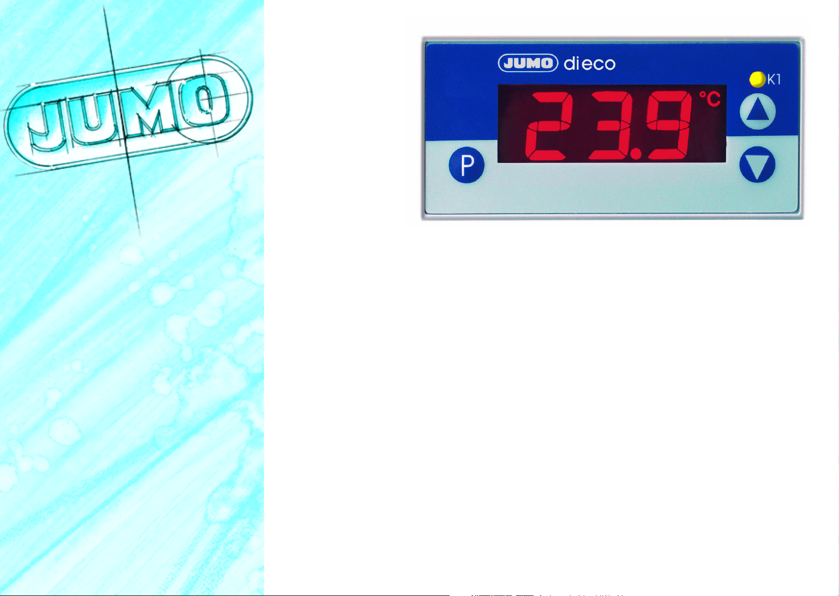
Jdi eco
Digitales Temperatur-Anzeigeinstrument
Digital Temperature Indicator
Indicateur de température numérique
B 70.1540.0 (B 95.1540.0)
Betriebsanleitung
Operating Instructions
Notice de mise en service
10.04/00440457
Page 2
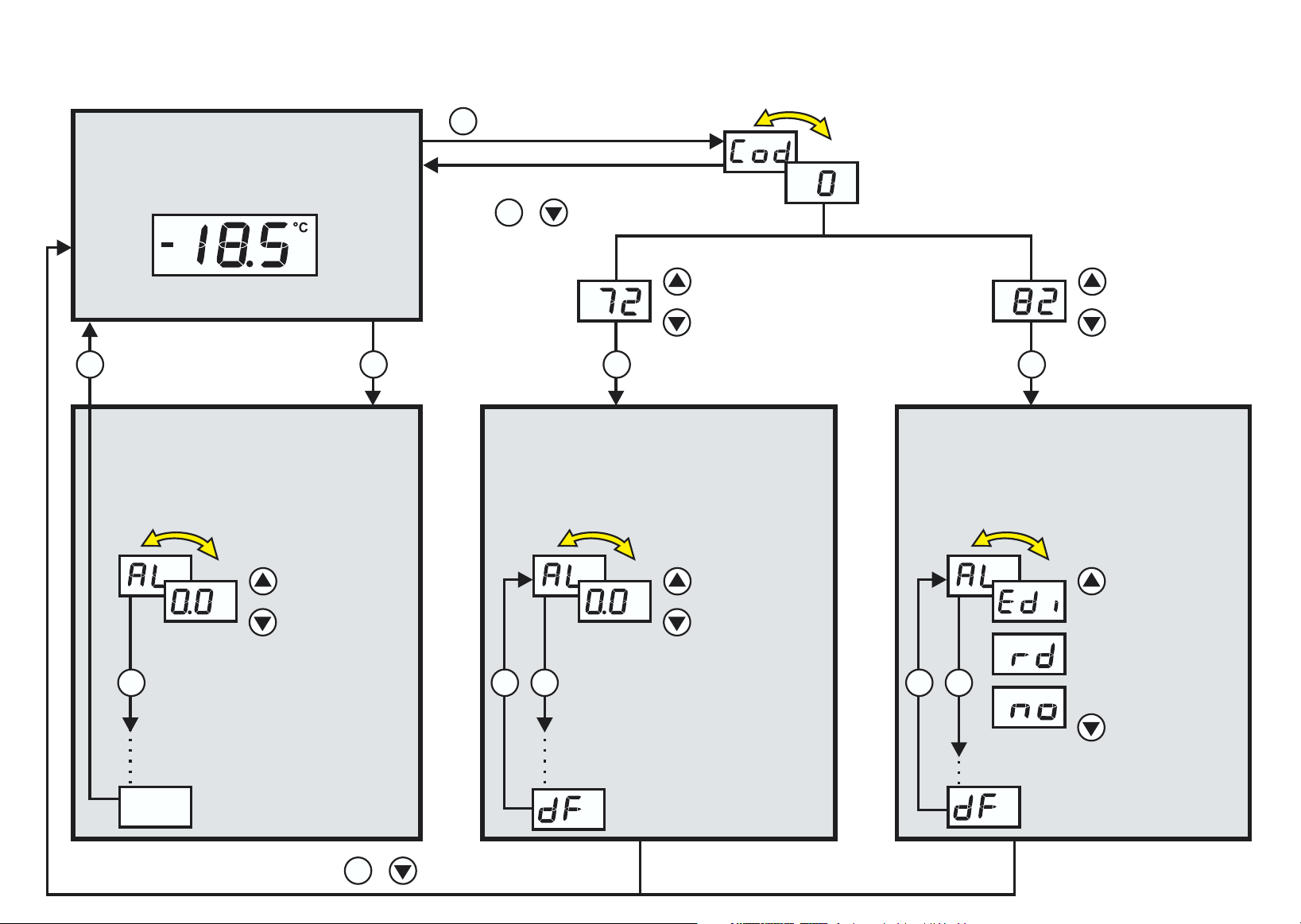
Funktionsübersicht
Istwertanzeige
oder 30
P P
Timeout
Sekunden
Bedienerebene
Hier können die in der Freigabeebene freigegebenen
angezeigt und verändert werden.
Anzeige wechselt Anzeige wechselt Anzeige wechselt
Parameter
> 3 Sekunden
P
30 TimeoutSekunden
oder
P
+
Parameterebene
Hier können alle Parameter
verändert werden.
(gleichzeitig)
P
Code eingeben
vergrößern
verkleinern
Anzeige wechselt
vergrößern
verkleinern
P
Freigabeebene
Parameter festlegen, die in der
Bedienerebene angezeigt werden
oder editierbar sind.
vergrößern
verkleinern
P
weitere Parameter &
& aus der
xxx
60 Sekunden Timeout oder
Freigabeebene
+ (gleichzeitig)
P
vergrößern
verkleinern
P
P P
weitere Parameter
letzter Parameter
P
weitere Parameter
editierbar
anzeigen
nicht
freigeben
Page 3

Inhalt
1 Geräteausführung identifizieren . . . . . . . . . . . . . . . . . . . . . . . . . . . . . . . . . . . . . . . . . . . . . 4
2 Montage . . . . . . . . . . . . . . . . . . . . . . . . . . . . . . . . . . . . . . . . . . . . . . . . . . . . . . . . . . . . . . . . 6
3 Elektrischer Anschluss . . . . . . . . . . . . . . . . . . . . . . . . . . . . . . . . . . . . . . . . . . . . . . . . . . . .7
3.1 Installationshinweise . . . . . . . . . . . . . . . . . . . . . . . . . . . . . . . . . . . . . . . . . . . . . . . . . . . . . . . 7
3.2 Anschlussplan . . . . . . . . . . . . . . . . . . . . . . . . . . . . . . . . . . . . . . . . . . . . . . . . . . . . . . . . . . . . 8
4 Gerät in Betrieb nehmen . . . . . . . . . . . . . . . . . . . . . . . . . . . . . . . . . . . . . . . . . . . . . . . . . . .9
4.1 Anzeige- und Bedienelemente . . . . . . . . . . . . . . . . . . . . . . . . . . . . . . . . . . . . . . . . . . . . . . . . 9
4.2 Bedienerebene . . . . . . . . . . . . . . . . . . . . . . . . . . . . . . . . . . . . . . . . . . . . . . . . . . . . . . . . . . . 10
4.3 Gerätefunktionen einstellen (Parameterebene) . . . . . . . . . . . . . . . . . . . . . . . . . . . . . . . . . . 11
4.4 Bedienrechte vergeben (Freigabeebene) . . . . . . . . . . . . . . . . . . . . . . . . . . . . . . . . . . . . . . .16
5 Technische Daten . . . . . . . . . . . . . . . . . . . . . . . . . . . . . . . . . . . . . . . . . . . . . . . . . . . . . . . . 17
5.1 Setup Programm . . . . . . . . . . . . . . . . . . . . . . . . . . . . . . . . . . . . . . . . . . . . . . . . . . . . . . . . . 20
6 Alarmmeldungen . . . . . . . . . . . . . . . . . . . . . . . . . . . . . . . . . . . . . . . . . . . . . . . . . . . . . . . .21
Inhalt
3
Page 4
1 Geräteausführung identifizieren
Das Typenschild ist auf der Unterseite des Gerätes aufgeklebt. Die angeschlossene Spannungsversorgung muss mit
der auf dem Typenschild angegebenen Spannung identisch sein.
Alle erforderlichen Einstellungen sind in der vorliegenden Betriebsanleitung beschrieben. Sollten trotzdem
H
Bei technischen Rückfragen
Service-Hotline:
Telefon:+49 661 6003-300 oder +49 661 6003-653
Telefax:+49 661 6003-9696300 oder +49 661 6003-881653
E-Mail:Service@jumo.net
bei der Inbetriebnahme Schwierigkeiten auftreten, bitten wir Sie, keine unzulässigen Manipulationen am Gerät vorzunehmen. Sie gefährden dadurch Ihren Garantieanspruch! Bitte setzen Sie sich mit der nächsten
Niederlassung oder mit dem Stammhaus in Verbindung.
Lesen Sie diese Betriebsanleitung, bevor Sie das Gerät in Betrieb nehmen. Bewahren Sie die Betriebsanleitung an einem für alle Benutzer jederzeit zugänglichen Platz auf. Bitte unterstützen Sie uns, diese Betriebsanleitung zu verbessern.
1 Geräteausführung identifizieren
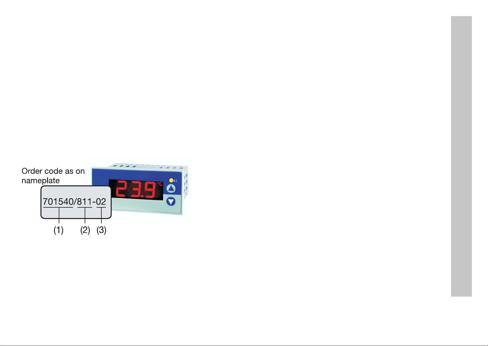
Bestellschlüssel
laut Typenschild
701540/811-02
(1) (2) (3)
Lieferumfang
1 Dichtung
1 Befestigungsrahmen
1 Betriebsanleitung 70.1540.0
4
Page 5

(1) Grundausführung
701540/ JUMO di eco
(2) Grundtypergänzung
Ausführung
8 werkseitig eingestellt, konfigurierbar innerhalb
der Messeingangsgruppe
9 nach Kundenangaben konfiguriert
Messeingangsgruppe
1 Pt 100 in Zweileiterschaltung
Pt 1000 in Zweileiterschaltung
KTY2X-6
2 Fe-CuNi „J“
Fe-CuNi „L“
NiCr-Ni „K“
3 0 ... 20 mA
4 ... 20 mA
4 0 ... 10 V
1 1 Wechsler 10A/250V
(3) Spannungsversorgung
02 AC 230V +10/-15% 48 ... 63 Hz
05 AC 115V +10/-15% 48 ... 63 Hz
31 DC 12 ... 24V +15/-15%/
AC 24V +15/-15% 48...63Hz
1 Geräteausführung identifizieren
1
(1) (2) (3)
Bestellschlüssel / -
Bestellbeispiel 701540 / 811 - 02
werkseitig eingestellt
1.) Messeingangsgruppen untereinander nicht umschaltbar
5
Page 6
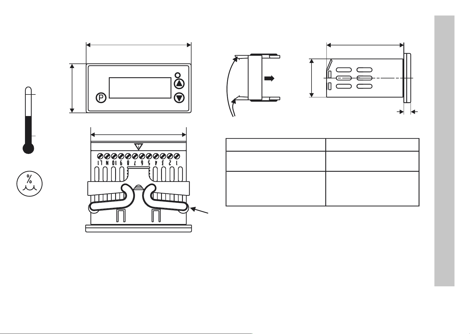
2Montage
°C
55
0
£ 75
36
76
68,5
K1
Befestigungsrahmen
56
28
Rastnasen
Frontrahmenmaß: 76mm x 36 mm
+2,5
Schalttafelausschnitt: 69 mm x 28,5 mm
Dicht-an-dicht-Einbau
bis max. 40°C
Umgebungstemperatur:
-0
Abstand der Geräte
10mm horizontal,
15mm vertikal
+1
-0
5
2 Montage
Federbügel
h Befestigungsrahmen vom Gerät abziehen.
h Gerät von vorne in den Schalttafelausschnitt einsetzen und auf korrekten Sitz der Frontrahmendichtung achten.
h Befestigungsrahmen von hinten auf Gehäuse aufschieben,
bis die Federbügel unter Spannung stehen und die Rastnasen oben und unten eingerastet sind.
6
Page 7

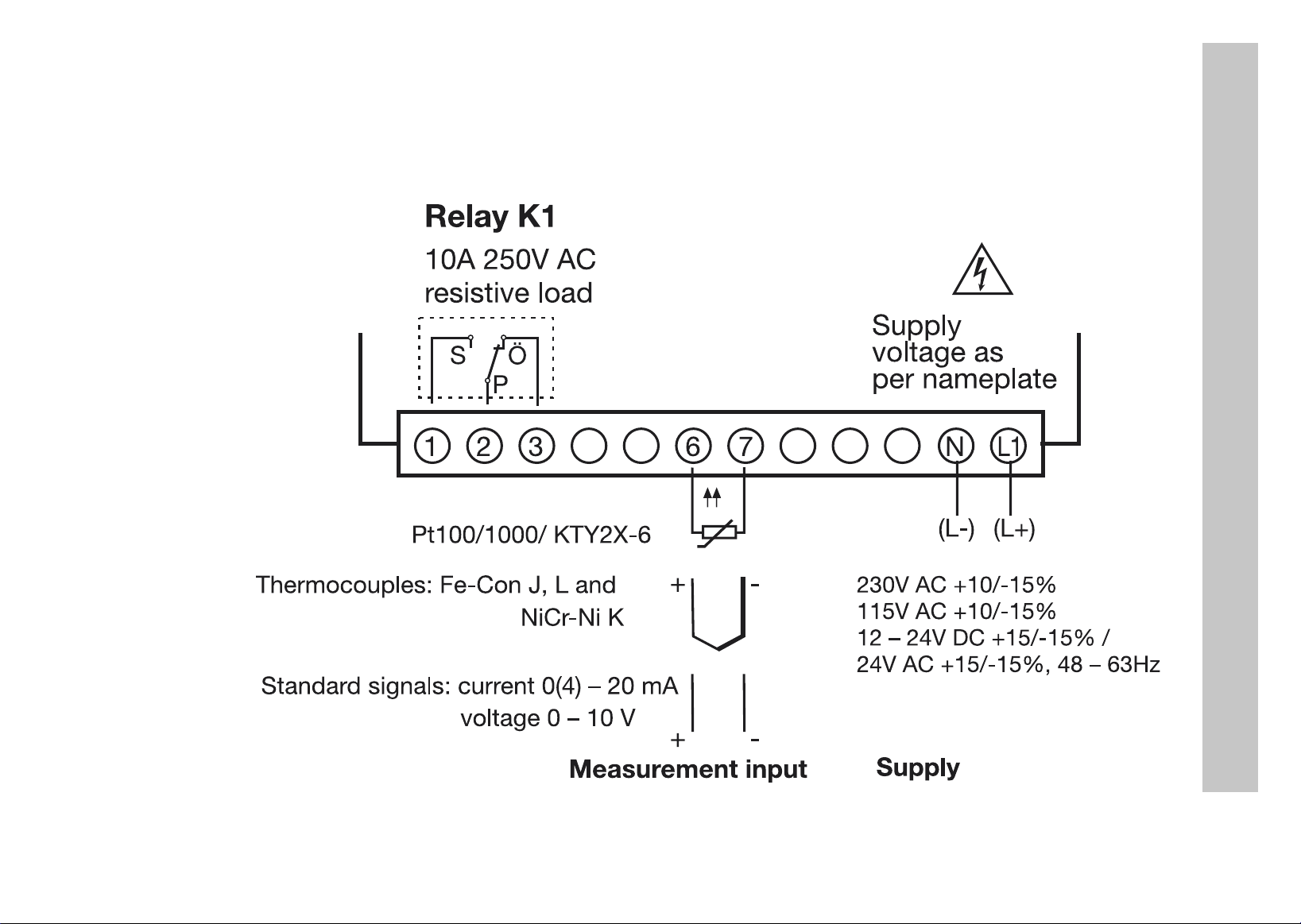
3 Elektrischer Anschluss
3.1 Installationshinweise
Bei der Wahl des Leitungsmaterials, bei der Installation, bei der Absicherung und beim elektrischen Anschluss
a
des Gerätes sind die Vorschriften der VDE 0100 „Bestimmungen über das Errichten von Starkstromanlagen mit
Nennspannungen unter 1000 V“ oder die jeweiligen Landesvorschriften zu beachten.
Der elektrische Anschluss darf nur von Fachpersonal durchgeführt werden.
a
Die elektromagnetische Verträglichkeit entspricht den in den technischen Daten aufgeführten Normen und Vor-
a
schriften.
Das Gerät ist nicht für die Installation in explosionsgefährdeten Bereichen geeignet und muß in ein Brand- /
a
Elektrisches Schutzgehäuse eingebaut werden.
Der Lastkreis muss auf den maximalen Relaisstrom abgesichert sein, um im Fall eines dortigen Kurzschlusses
a
ein Verschweißen der Ausgangsrelais zu verhindern.
Keine weiteren Verbraucher an die Schraubklemmen für die Spannungsversorgung des Gerätes anschließen.
a
Die äußere Absicherung der Spannungsversorgung sollte, abhängig vom Leitungsquerschnitt, einen Wert von
a
1A nicht unterschreiten.Das Gerät allpolig vom Netz trennen, wenn bei Arbeiten spannungsführende Teile
berührt werden können (z.B über einen separaten Netzschalter).
3 Elektrischer Anschluss
Spannungsversorgung Messeingang und Spannungsversorgung
a
AC 230V und AC 115V kurzschlussfest galvanisch voneinander getrennt
DC12..24V und AC24V nicht kurzschlussfest nicht galvanisch voneinander getrennt
7
Page 8
3.2 Anschlussplan
Der elektrische Anschluss
V
darf nur von Fachpersonal
durchgeführt werden!
Relais K1
AC 250V/10A
ohmsche Last
S
Ö
P
3 Elektrischer Anschluss
Spannungsversorgung
lt. Typenschild
Pt100/1000/ KTY2X-6
Thermoelemente Fe-CuNi J,L und
NiCr-Ni K
Einheitssignale Strom 0(4) ... 20 mA
Spannung 0 ... 10 V
Messeingang
63217
J
+
+
-
-
AC 230V +10/-15%
-
AC 115V +10/-15%
-
DC 12...24V +15/-15%
-/
AC 24V +15/-15%, 48 ... 63Hz
Spannungsversorgung
N
(L-)
L1
(L+)
8
Page 9
4 Gerät in Betrieb nehmen
4.1 Anzeige- und Bedienelemente
LC-Display 13 mm hohe 3-stellige Segmentanzeige und Symbole für
°C, °F, min und s mit roter Hintergrundbeleuchtung
Schaltstellungsanzeige
Tasten Programmieren
SetupSchnittstelle
LED K1 leuchtet, wenn das Relais K1 angezogen ist.
LED K1 erlischt, wenn das Relais K1 abgefallen ist.
Parameterwert vergrößern
Bedienstatus in Freigabeebene wählen
Parameterwert verkleinern
Bedienstatus in Freigabeebene wählen
+
+
Das Gerät wird über ein PC-Interface mit TTL/RS232
Umsetzer und Adapter (3 Stifte) mit einem PC verbunden
Versionsanzeige
Exit, Sprung in die Grundstellung
4 Gerät in Betrieb nehmen
Ist am Gerät alles korrekt angeschlossen, zeigt es die aktuelle Temperatur an. Erscheint eine Alarmmeldung, siehe
Kapitel 6 „Alarmmeldungen“. Das Relais arbeitet je nach eingestelltem Relaistyp ( ), siehe Kapitel 4.3 „Gerätefunktionen einstellen (Parameterebene)“.
9
Page 10
4.2 Bedienerebene
H
In der Bedienerebene können die in der Freigabeebene freigegebenen Parameter angezeigt und verändert werden.
h Taste drücken (nur kurz drücken). Es erscheint der erste änderbare Parameter, z.B. . Es wird
h Mit den Tasten und Wert im angegebenen Wertebereich einstellen.
h Einstellungen mit quittieren.
h Nächsten Parameter einstellen, siehe Funktionsübersicht auf der ersten Innenseite.
Timeout:
Wird 30 Sekunden lang keine Taste bedient, schaltet das Gerät automatisch in die Temperaturanzeige zurück, siehe Funktionsübersicht auf der ersten Innenseite.
abwechselnd der Parametername und der aktuelle Wert angezeigt.
4 Gerät in Betrieb nehmen
10
Page 11
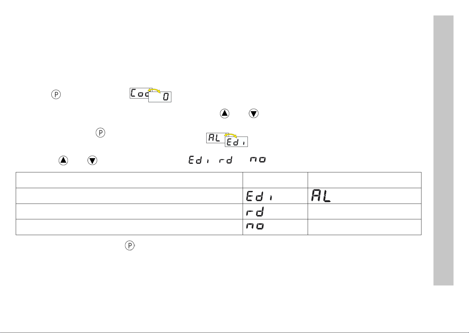
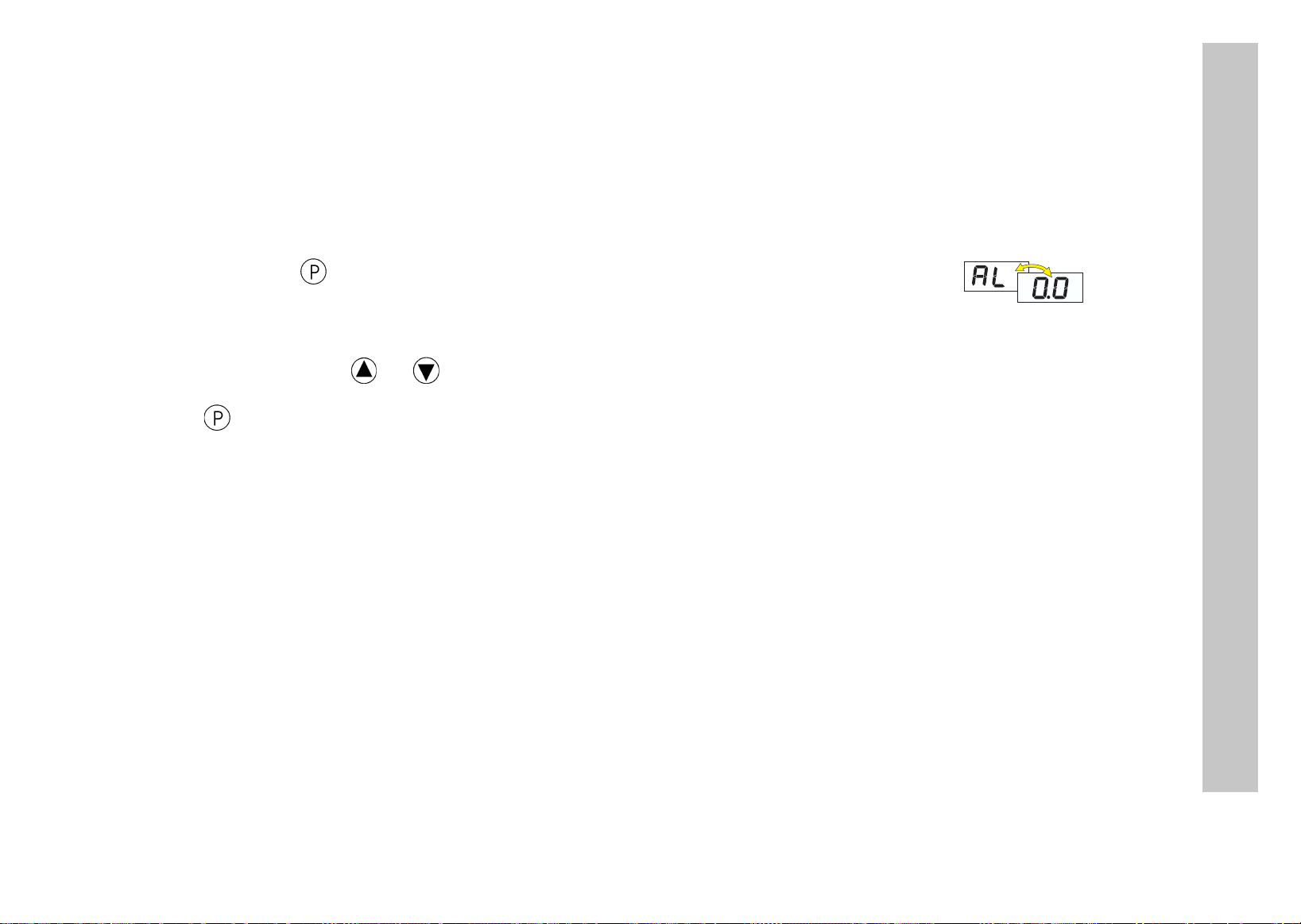
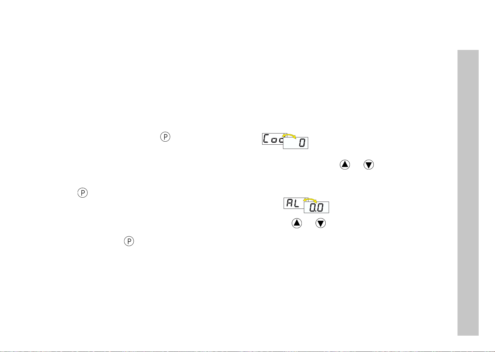
4.3 Gerätefunktionen einstellen (Parameterebene)
H
In der Parameterebene werden Gerätefunktionen und Werte eingestellt.
h Taste 3 Sekunden lang drücken und es erscheint abwechselnd .
h Code 72 für den Zugang zur Parameterebene mit den Tasten und einstellen.
h Mit quittieren,
h Mit den Tasten und Wert im angegebenen Wertebereich einstellen.
h Einstellungen mit quittieren.
Timeout:
Wird 60 Sekunden lang keine Taste bedient, schaltet das Gerät automatisch in die Temperaturanzeige zurück, siehe Funktionsübersicht auf der ersten Innenseite.
Je länger die Taste gedrückt wird, desto schneller verändert sich der Wert.
Parametername und Wert erscheinen abwechselnd, z.B. .
4 Gerät in Betrieb nehmen
h Nächsten Parameter einstellen, siehe Funktionsübersicht auf der ersten Innenseite.
H
Ausblendung von Parametern:
In der folgenden Tabelle sind alle Parameter für jeden Gerätetyp aufgeführt.
Je nach Typenbezeichnung auf dem Typenschild, werden nicht benötigte Parameter ausgeblendet.
11
Page 12
Anzeigerparameter
Parameter Bedeutung
Alarmwert (Grenzwert für Relais und LED)
Ein Messwert wird als Alarm gewertet, wenn
- der aktuelle Wert größer ist als Alarmwert + ½ Hysterese und
- ununterbrochen länger ansteht, als unter Alarmunterdrückungzeits
konfiguriert.
Ein Alarm wird wieder zurückgesetzt, wenn
- der aktuelle Wert kleiner als Alarmwert - ½ Hysterese ist.
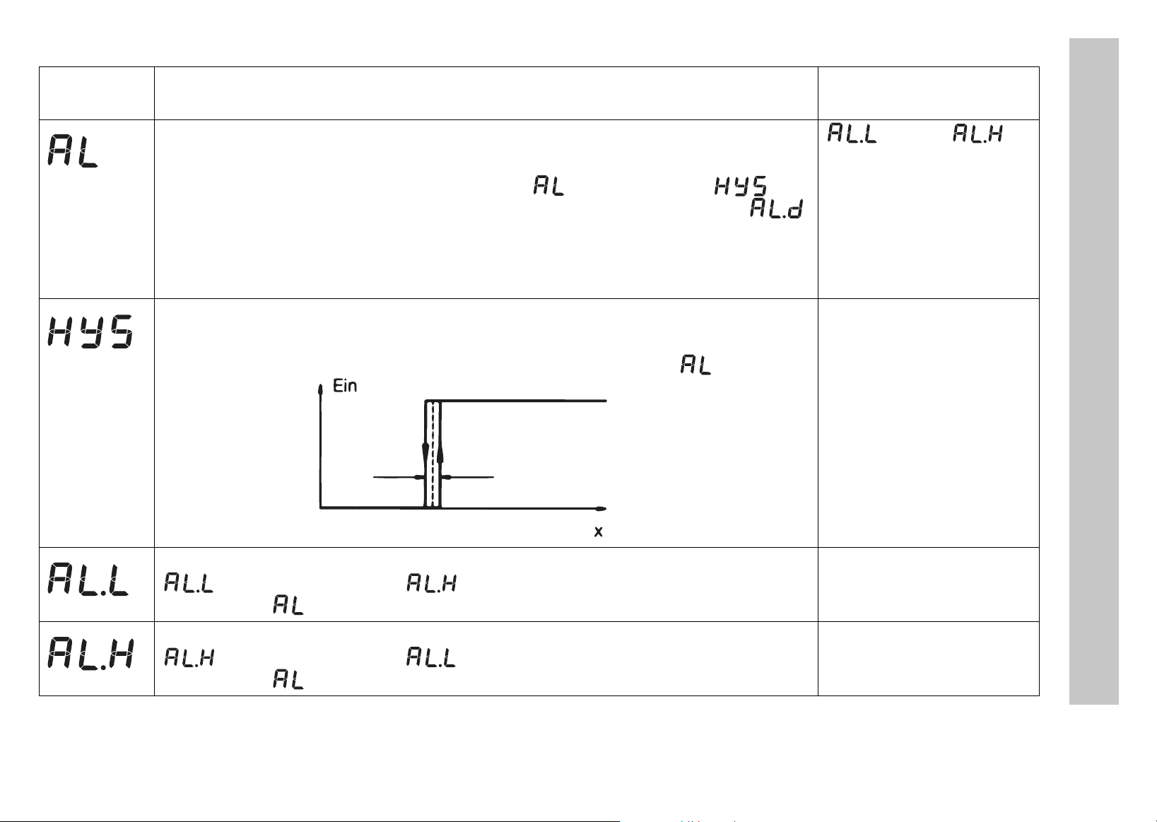
Hysterese
Wird zur Ermittlung eines Alarmes herangezogen.
Die Hysterese befindet sich symmetrisch um den Grenzwert .
Wertebereich
von...werkseitig...bis
... 0 …
4 Gerät in Betrieb nehmen
0.4 ... 1.0 ... 99.9K/°F
HyS
untere Alarmgrenzwert
dient zusammen mit zur Begrenzung des Wertebereiches des
Alarmwertes .
obere Alarmgrenzwert
dient zusammen mit zur Begrenzung des Wertebereiches des
Alarmwertes .
AL
-350 ...
-350 ... 500 ... 999°C/°F
-200
... 999°C/°F
12
Page 13
Parameter Bedeutung
Wertebereich
von...werkseitig...bis
Alarmunterdrückungszeit
Für diese Zeit wird ein Alarm nicht als Alarm gewertet. Im Display blinkt die
LED K1. Ist ein Alarm länger als vorhanden, wird er als Alarm gewertet, die LED K1 leuchtet und das Relais wird entsprechend Parameter
geschaltet (siehe Parameter ).
Einschaltverzögerungszeit nach Netz-Ein
Zum zeitversetzten Einschalten der Alarmüberwachung. Während dieser
Zeit werden keine Alarme ausgewertet, nur Fühlerfehler.
Relaistyp
0: Relais arbeitet im Alarmfall als Öffner
1: Relais arbeitet im Alarmfall als Schließer
Verhalten bei Messbereichsüber- oder -unterschreitung
0: Relais fällt sofort ab
1: Relais zieht sofort an
0 ... 60min
4 Gerät in Betrieb nehmen
0 ... 60min
0 … 1
0 … 1
13
Page 14
Parameter Bedeutung
Eingang
Wertebereich
von...werkseitig...bis
Angeschlossener Messwertgeber in Zweileiterschaltung
Messeingangsgruppe 1 bei Typ: 701540/X11-XX
Messeingangsgruppe 2 bei Typ: 701540/X21-XX Fe-CuNi „J“ :
Messeingangsgruppe 3 bei Typ: 701540/X31-XX 0(4)... 20 mA:
Messeingangsgruppe 4 bei Typ: 701540/X41-XX 0 ... 10 V: /
Anfangswert für Anzeigebereich bei Messeingang Spannung oder Strom
Beispiel: Eingangssignal 4 ... 20mA soll von -10...50 auf der Anzeige abgebildet werden. Für S.cL= -10 und S.cH=50 einstellen.
Endwert für Anzeigebereich bei Messeingang Spannung und Strom -999 ... 100... +999
Signal für Messeingang Strom: 0 = 0...20mA
1 = 4...20mA
Pt 100:
Pt 1000:
KTY2X-6:
oder
Fe-CuNi „L“:
NiCr-Ni „K“:
oder
/
-999 ... 0... +999
0, 1
4 Gerät in Betrieb nehmen
Offset Istwert
Istwertoffset in K, °F oder Digit (keine Einheit)
-99,9 ... 0,0 ... 99,9
14
Page 15
Parameter Bedeutung
Wertebereich
von...werkseitig...bis
Leitungsabgleichwiderstand
Dieser Wert dient zur Kompensation des Widerstands der Fühlerleitung und
ist abhängig von der Leitungslänge.
Für eine bestmögliche Temperaturmessung muss hier der ohmsche Widerstand der Fühlerleitung bei kurzgeschlossenem Fühler eingegeben werden.
Wenn der Gesamtwiderstand am Messeingang (Messwertgeberwider-
A
Einheit
für die angezeigten Istwert
A
Filterzeitkonstante
Zur Anpassung des digitalen Eingangsfilters.
Bei einem Signalsprung werden nach der Filterzeitkonstante 63% der Änderungen erfasst.
Werte zwischen 0,1 und 0,7 werden als 0,8 interpretiert (Abtastzeit).
Wenn die Filterzeitkonstante groß ist:
- hohe Dämpfung von Störsignalen
- langsame Reaktion der Istwertanzeige auf Istwertänderungen
stand + eingestellter Wert für OF.r) bei Pt100: 320
KTY2x-6: 3200 Ω überschreitet, kommt es zu einem Messfehler !
Nur der Istwert am Messeingang wird bei der Umstellung in °F entsprechend umgerechnet. Alle anderen Größen bleiben in ihrem
Wert erhalten.
Ω und bei Pt1000/
0,0 ... 99,9 in
°C oder °F
no (= keine Einheit)
0,1 ... 0,8 ... 99,9s
Ω
4 Gerät in Betrieb nehmen
H
Mit > 3 Sekunden zurück zum 1. Parameter AL der Parameterebene.
15
Page 16
4.4 Bedienrechte vergeben (Freigabeebene)
H
Die Einstellung in der Freigabeebene legt Bedienrechte fest, die darüber entscheiden, ob ein Parameter in der Bedienebene erscheint, editiert werden kann oder gar nicht erscheint.
h Taste 3 Sekunden lang drücken und erscheint.
h Code 82 für den Zugang zur Freigabeebene mit den Tasten und einstellen.
h Mit quittieren
h Mit den Tasten und ein Bedienrecht , oder einstellen.
Bedienrecht Anzeige werkseitig
Parameter ist sichtbar und einstellbar
Timeout:
Wird 60 Sekunden lang keine Taste bedient, schaltet das Gerät automatisch in die Istwertanzeige zurück,
siehe Funktionsübersicht auf der ersten Innenseite.
Parameter und Bedienrecht blinken abwechselnd z.B. .
4 Gerät in Betrieb nehmen
Parameter ist nur sichtbar -
Parameter erscheint nicht alle anderen Parameter
h Einstellungen mit quittieren.
h Nächsten Parameter einstellen, siehe Funktionsübersicht auf der ersten Innenseite.
16
Page 17
5 Technische Daten
Messeingang Bezeichnung Messbereich Messgenauigkeit1/
Umgebungstemperatureinfluss
Widerstandsthermometer
Messstrom bei Pt100: 0,2 mA, bei Pt1000, KTY2X-6 und Widerstand: 0,02 mA
Leitungsabgleich über den Parameter Leitungsabgleichwiderstand einstellbar
Gesamtwiderstand Sensor+Leitung darf bei Pt100 320Ω und bei Pt1000, KTY2X-6 und Widerstand 3200Ω nicht
überschreiten.
Thermoelemente
Pt 100 DIN EN 60751 -200 … +600°C 0,1%/ ≤100ppm/K wird erkannt wird erkannt
Pt 1000 DIN EN 60751 -200 … +600°C 0,1%/ ≤100ppm/K wird erkannt wird erkannt
KTY2X-6 (PTC) -50 ... +150 °C 1%/ ≤100ppm/K wird erkannt wird erkannt
Widerstand 0...3000 Ω Kundentabelle
Fe-CuNi „J“ DIN EN
60584
Fe-CuNi „L“ DIN 43710 -200 ... +900 °C 0,4%/ ≤100ppm/K
-200 ... +999 °C 0,4%/ ≤100ppm/K
3
0,1%/ ≤100ppm/K 3= 0Ω wird erkannt
Erkennung von ...
Fühlerkurzschluss
2
- wird erkannt
2
- wird erkannt
Fühlerbruch
5 Technische Daten
NiCr-Ni „K“ DIN EN
60584
-10...60 mV Kundentabelle
Für den Spannungseingang (-10...60 mV) kann die Klemmentemperaturkompensation für Thermoelemente verwendet werden.
Interne Klemmentemperaturkompensation über Setup-Programm abschaltbar (0°C).
-200 ... +999 °C 0,4%/ ≤100ppm/K
3
0,1%/ ≤100ppm/K 3- wird erkannt
2
- wird erkannt
17
Page 18
Messeingang Bezeichnung Messbereich Messgenauigkeit1/
Umgebungstemperatureinfluss
Erkennung von ...
Fühlerkurz-
Fühlerbruch
schluss
Strom 0 ... 20 mA -2 ... 22 mA
0,1%/ ≤100ppm/K
3
skalierbar mit
und
oder Kundentabelle
4 ... 20 mA 2,4 ... 21,6 mA
0,1%/ ≤100ppm/K 3wird erkannt wird erkannt
skalierbar mit
und
Eingangswiderstand R
E
≤ 3Ω
Spannung 0 ... 10 V -1 ... 11 V
0,1%/ ≤100ppm/K - -
skalierbar mit
und
oder Kundentabelle
Eingangswiderstand RE ≥ 100kΩ
1.) Die Genauigkeiten beziehen sich auf den Messbereichsumfang.
2.) gültig ab -50°C
3.) Eine gültige Kundentabelle muß über Setup-Programm eingegeben und im Gerät auf umgeschaltet werden.
Dadurch kann sich die Messgenauigkeit verringern.
--
5 Technische Daten
18
Page 19

Umwelteinflüsse
Umgebungstemperaturbereich 0 ... +55°C, bei Dicht-an-Dicht Montage: 0 ... +40°C
Lagertemperaturbereich -40 ... +70°C
Klimafestigkeit ≤ 75% rel. Feuchte ohne Betauung
Reinigung und Pflege
der Frontplatte
Die Frontplatte kann mit handelsüblichem Wasch-, Spül- und Reinigungsmitteln
gesäubert werden. Kein Lösungsmittel, wie z. B. Spiritus, Waschbenzin, P1 oder
Xylol, verwenden.
Ausgang
Relais (Wechselkontakt) 150.000 Schaltungen bei AC 250V/10A ohmsche Last
Spannungsversorgung
Spannungsversorgung AC 230V +10/-15%, 48 ... 63Hz oder AC 115V +10/-15%, 48 ... 63Hz
(galvanische Trennung zum Messeingang)
DC 12 ... 24V +15/-15%, AC 24V +15/-15%, 48 ... 63Hz
(keine galvanische Trennung zum Messeingang)
Leistungsaufnahme < 3VA
Gehäuse
Material Polycarbonat
Montage in Schalttafelausschnitt mit Frontrahmendichtung
Einbaulage beliebig
Gewicht ca. 160g
5 Technische Daten
Schutzart frontseitig IP65, rückseitig IP20
Brennbarkeitsklasse UL 94 VO
19
Page 20
Elektrische Daten
Datensicherung EEPROM
Anschlussart Schraubklemmen für Drahtquerschnitte bis max. 4 mm
und bis max. 2,5 mm2 feinstdrähtig.
EMV
- Störaussendung
- Störfestigkeit
Einsatzbedingungen Das Gerät ist als Einbaugerät ausgelegt.
Elektrische Sicherheit nach DIN EN 61 010, Teil 1,
Überspannungskategorie III, Verschmutzungsgrad 2
Industrie-Anforderung
EN 61326
Klasse B
2
eindrähtig
5.1 Setup Programm
Das Programm und das Interface mit Adapter sind als Zubehör erhältlich und bieten folgende Möglichkeiten:
- einfache und komfortable Parametrierung und Archivierung über PC
- einfaches duplizieren der Parameter bei Geräten gleichen Typs
- Möglichkeit der Eingabe einer Linearisierungstabelle
Hard- und Softwaremindestvoraussetzungen:
- PC Pentium 100 oder kompatibel
5 Technische Daten
- 128 MB RAM, 16 MB freier Festplattenspeicher
- CD-ROM Laufwerk
- freie COM-Schnittstelle
- Microsoft Windows 98/ME/NT4.0/2000/XP
h PC-Interface mit der RS 232 Schnittstelle des PC verbinden
h Schwarzen Adapter (3 Stifte) von unten ins Gerät einstecken
20
Page 21
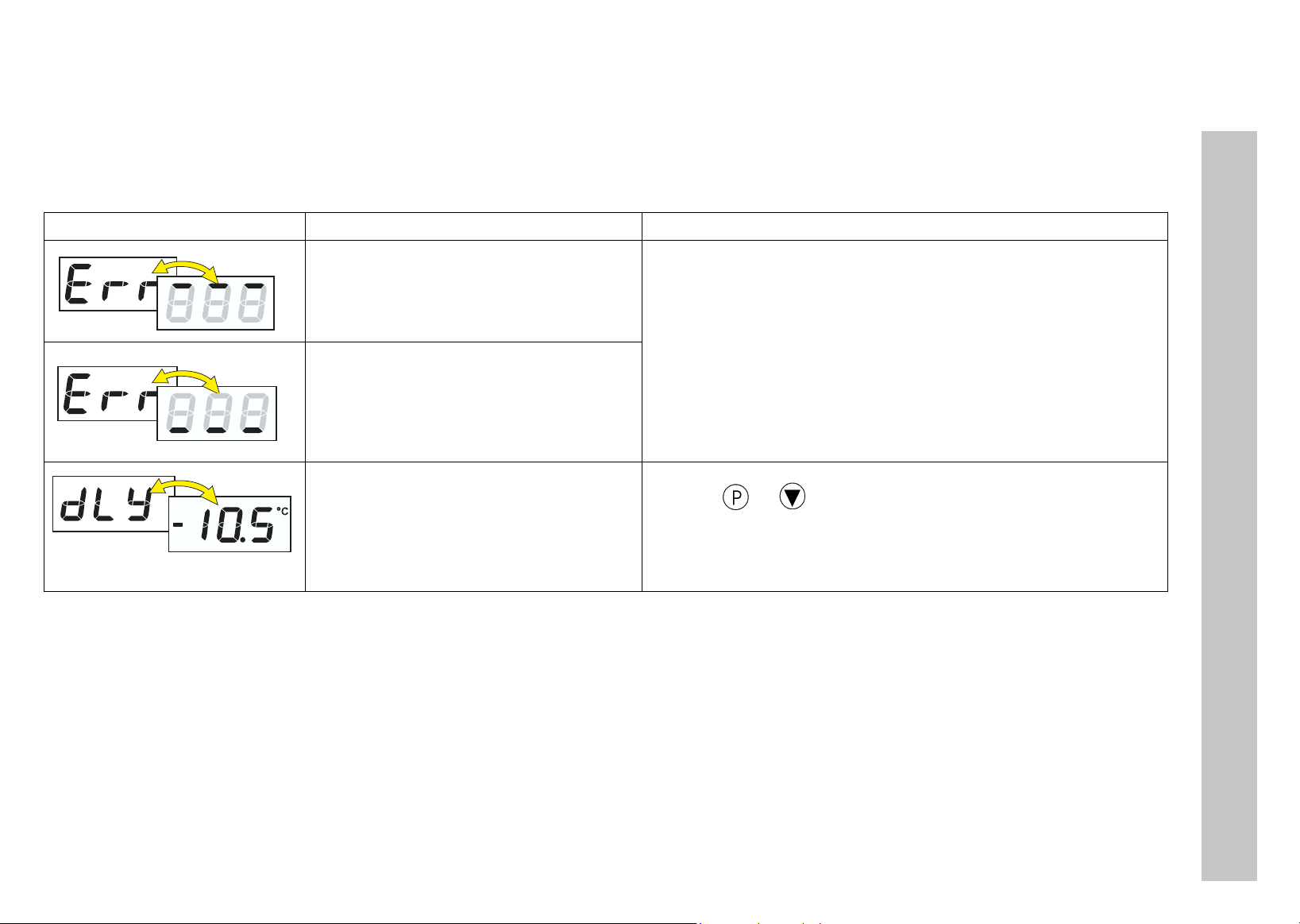
6Alarmmeldungen
In der Temperaturanzeige können folgende Alarmmeldungen angezeigt werden:
Fehleranzeige Ursache Abhilfe
Aktuelle Temp.
Anzeigeüberlauf
Der Wert ist zu groß und liegt
außerhalb des Messbereichs.
Anzeigeunterlauf
Der Wert ist zu klein und liegt
außerhalb des Messbereichs.
Zeit für Einschaltverzögerung
nach Netz-Ein läuft ab.
Bei Anzeigeüber- oder -unterlauf
wird die Einschaltverzögerung
verlassen.
- Sensor und Anschlussleitung auf Beschädigung
oder Kurzschluss überprüfen
- Überprüfen, ob der richtige Sensor eingestellt
oder angeschlossen ist
v Kapitel 4 „Gerät in Betrieb nehmen“
h Einschaltverzögerung abbrechen
mit +
6 Alarmmeldungen
21
Page 22

Page 23

JUMO GmbH & Co. KG
JUMO
JUMO
Hausadresse:
Moltkestraße 13 - 31
36039 Fulda, Germany
Lieferadresse:
Mackenrodtstraße 14
36039 Fulda, Germany
Postadresse:
36035 Fulda, Germany
Telefon: +49 661 6003-0
Telefax: +49 661 6003-500
E-Mail: mail@jumo.net
Internet: www.jumo.net
Mess- und Regelgeräte Ges.m.b.H.
Pfarrgasse 48
1232 Wien, Austria
Telefon: +43 1 610610
Telefax: +43 1 6106140
E-Mail: info@jumo.at
Internet: www.jumo.at
Mess- und Regeltechnik AG
Seestrasse 67, Postfach
8712 Stäfa, Switzerland
Telefon: +41 44 928 24 44
Telefax: +41 44 928 24 48
E-Mail: info@jumo.ch
Internet: www.jumo.ch
Page 24

Digital Indicator
B 70.1540.0 (B 95.1540.0)
Operating Instructions
10.04
Page 25

Overview of operation
Contents
Page 26

1 Instrument identification . . . . . . . . . . . . . . . . . . . . . . . . . . . . . . . . . . . . . . . . . . . . . . . . . . . 4
2 Mounting . . . . . . . . . . . . . . . . . . . . . . . . . . . . . . . . . . . . . . . . . . . . . . . . . . . . . . . . . . . . . . . . 6
3 Electrical connection . . . . . . . . . . . . . . . . . . . . . . . . . . . . . . . . . . . . . . . . . . . . . . . . . . . . . . 7
3.1 Installation notes . . . . . . . . . . . . . . . . . . . . . . . . . . . . . . . . . . . . . . . . . . . . . . . . . . . . . . . . . .7
3.2 Connection diagram . . . . . . . . . . . . . . . . . . . . . . . . . . . . . . . . . . . . . . . . . . . . . . . . . . . . . . . . 8
4 Commissioning the instrument . . . . . . . . . . . . . . . . . . . . . . . . . . . . . . . . . . . . . . . . . . . . . . 9
4.1 Displays and controls . . . . . . . . . . . . . . . . . . . . . . . . . . . . . . . . . . . . . . . . . . . . . . . . . . . . . . . 9
4.2 Operating level . . . . . . . . . . . . . . . . . . . . . . . . . . . . . . . . . . . . . . . . . . . . . . . . . . . . . . . . . . .10
4.3 Setting the instrument functions (parameter level) . . . . . . . . . . . . . . . . . . . . . . . . . . . . . . . . 11
4.4 Allocating user rights (enabling level) . . . . . . . . . . . . . . . . . . . . . . . . . . . . . . . . . . . . . . . . . . 16
5 Technical data . . . . . . . . . . . . . . . . . . . . . . . . . . . . . . . . . . . . . . . . . . . . . . . . . . . . . . . . . . 17
5.1 Setup program . . . . . . . . . . . . . . . . . . . . . . . . . . . . . . . . . . . . . . . . . . . . . . . . . . . . . . . . . . .20
6 Alarm messages . . . . . . . . . . . . . . . . . . . . . . . . . . . . . . . . . . . . . . . . . . . . . . . . . . . . . . . . . 21
Contents
3
Page 27
1 Instrument identification
The nameplate is glued to the bottom of the instrument. The supply voltage that is connected must correspond to the
voltage specified on the nameplate.
H
All necessary settings are described in these Operating Instructions. If any difficulties should still arise during start-up, you are asked not to carry out any unauthorized manipulations on the unit. You could endanger
your rights under the instrument warranty! Please contact the nearest subsidiary or the head office.
Please read these operating instructions carefully before commissioning the instrument. Keep the manual in
a place that is accessible to all users at all times. Please assist us to improve these operating instructions,
where necessary.
Delivery package
1 seal
1 mounting frame
1 Operating Instructions 70.1540.0
1 Instrument identification
4
Page 28

(1) Basic version
701540/ JUMO di eco
(2) Basic type extension
Version
8 factory-set, configurable within the
measurement input group
9 configured to customer specification
Measurement input group
1 Pt100 in 2-wire circuit
Pt 1000 in 2-wire circuit
KTY2X-6
2 Fe-Con J
Fe-Con L
NiCr-Ni K
3 0—20 mA
4—20 mA
4 0—10 V
1 1 changeover 10A/250V
(3) Supply
02 230V AC +10/-15% 48 — 63Hz
05 115V AC +10/-15% 48 — 63Hz
31 12 — 24V DC +15/-15% /
24V AC +15/-15% 48 — 63Hz
1
1 Instrument identification
(1) (2) (3)
Order code / -
Order example 701540 / 811 - 02
factory-set
1.) It is not possible to switch from one measurement input group to
another.
5
Page 29
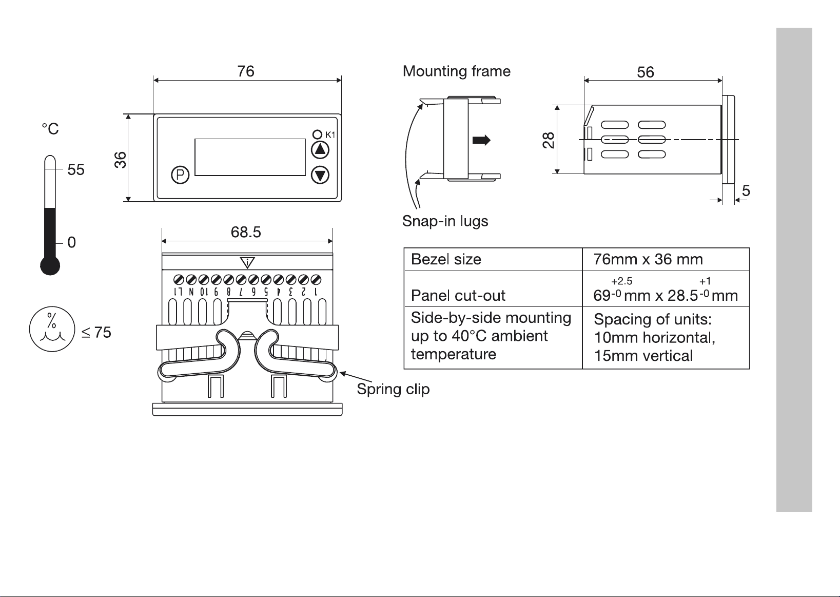
2Mounting
2 Mounting
h Pull off mounting frame from instrument.
h Insert the instrument from the front into the panel cut-out and make sure that the bezel seal is seated correctly.
h From the back, push mounting frame onto the housing
until the spring clips are under tension and the snap-in lugs have engaged at top and bottom.
6
Page 30

3 Electrical connection
3.1 Installation notes
The choice of cable, the installation, the fusing and the electrical connection of the instrument must conform to
a
the requirements of VDE 0100 “Regulations on the Installation of Power Circuits with nominal voltages below
1000 V” or the appropriate local regulations.
The electrical connection must only be carried out by qualified personnel.
a
The electromagnetic compatibility conforms to the standards and regulations listed under Technical data.
a
The instrument is not suitable for installation in areas with an explosion hazard and must be built into a housing
a
that provides protection against fire /electrical hazards.
The load circuit must be fused for the maximum relay current in order to prevent welding of the output relay
a
contacts in the event of a short circuit.
Do not connect any additional loads to the supply terminals of the instrument.
a
The external fuse of the supply should not be rated below 1A, depending on the conductor cross-section. If
a
contact with live components is possible while working on the instrument, it must be disconnected on all poles
from the supply (e.g. via a separate mains supply switch).
Supply Measurement input and supply
a
3 Electrical connection
230V AC and 115V AC short-circuit-proof electrically isolated from each other
12 — 24V DC and 24V AC not short-circuit-proof not electrically isolated from each other
7
Page 31
3.2 Connection diagram
The electrical connection
V
must only be carried out by
qualified personnel !
3 Electrical connection
8
Page 32

4 Commissioning the instrument
4.1 Displays and controls
LC display 3-digit segment display, 13 mm high, with symbols for °C,
°F, min and s, with red background lighting
Status display LED K1 lights up when relay K1 is energized.
LED K1 goes out when relay K1 is de-energized.
Keys programming
increase parameter value
select operational status in enabling level
decrease parameter value
select operational status in enabling level
+
+
version display
exit, jump to basic status
4 Commissioning the instrument
Setup
interface
When everything is connected up correctly on the instrument, the present temperature is displayed. If an alarm message appears, see Chapter 6 “Alarm messages”. The relay operates according to the selected relay type ( ), see
Chapter 4.3 “Setting the instrument functions (parameter level)”.
The instrument is linked to the PC via a PC interface with
TTL/RS232 converter and adapter (3 pins).
9
Page 33

4.2 Operating level
H
The parameters that have been enabled at the enabling level can be displayed and modified at the operating level.
h Press (only briefly). The first parameter that can be modified appears, e.g. . Parameter name
h Use the and keys the set the value within the specified value range.
h Acknowledge settings with .
h Set the next parameter, see Overview of operation on the front inside page.
Time-out:
If no key is pressed for 30 seconds, then the instrument automatically switches back to the temperature display, see Overview of operation on the front inside page.
and present value are displayed alternately.
4 Commissioning the instrument
10
Page 34

4.3 Setting the instrument functions (parameter level)
H
The instrument functions and values are set at the parameter level.
h Press for 3 seconds and will appear in alternation.
h Set code 72 for accessing the parameter level using the and keys.
h Acknowledge with ,
h Use the and keys to set the value within the specified value range.
h Acknowledge settings with .
Time-out:
If no key is pressed for 60 seconds, the instrument automatically switches back to temperature display, see
Overview of operation on the front inside page.
The longer the key is pressed, the faster the value will change.
parameter name and value appear alternately, e.g. .
4 Commissioning the instrument
h Set the next parameter, see Overview of operation on the front inside page.
H
Switching parameters out of display:
The table below lists all the parameters for each instrument type.
Depending on the type designation on the nameplate, parameters that are not required are hidden.
11
Page 35

Indicator parameters
Parameter Meaning
Alarm value (limit for relay and LED)
A measured value is considered to be an alarm if
- present value is larger than alarm value + ½ hysteresis and
- has been continuously present for longer than configured under the alarm
suppression time .
An alarm is reset if
- present value is smaller than the alarm value - ½ hysteresis.
Hysteresis
It is used to determine an alarm.
The hysteresis lies symmetrically about the limit value .
Value range
from...factory-set...to
4 Commissioning the instrument
... 0 …
0.4 ... 1.0 ... 99.9°C/°F
Low alarm limit
, together with , is used to limit the value range for the alarm
value .
High alarm limit
, together with , is used to limit the value range for the alarm
value .
-350 ...
-350 ... 500 ... 999°C/°F
-200
... 999°C/°F
12
Page 36

Parameter Meaning
Value range
from...factory-set...to
Alarm suppression time
An alarm is not considered to be an alarm for this period. The LED K1
flashes in the display. If an alarm is present for longer than , then it is
considered to be an alarm, the LED K1 lights up and the relay is switched in
accordance with the parameter (see parameter ).
Switch-on delay after power-on
For the time-delayed switch-on of the alarm monitoring. No alarms are evaluated during this time, only probe errors.
Relay type
0: relay operates as a break contact in the event of an alarm
1: relay operates as a make contact in the event of an alarm
Response to over/underrange
0: relay drops out at once
1: relay pulls in at once
0 ... 60min
4 Commissioning the instrument
0 ... 60min
0 … 1
0 … 1
13
Page 37

Parameter Meaning
Value range
from...factory-set...to
Input
Sensor connected in 2-wire circuit
Measurement input group 1 on Type: 701540/X11-XX
Measurement input group 2 on Type: 701540/X21-XX Fe-Con J :
Measurement input group 3 on Type: 701540/X31-XX 0(4)... 20 mA:
Measurement input group 4 on Type: 701540/X41-XX 0 ... 10 V: /
Start value for indication range with measurement input voltage or current
Example: input signal 4 — 20mA is to be represented in the display from
-10 to 50. Set S.cL= -10 and S.cH=50.
End value for indication range with measurement input voltage or current -999 ... 100... +999
Pt100:
Pt1000:
KTY2X-6:
or
Fe-Con L:
NiCr-Ni K:
or
/
-999 ... 0... +999
4 Commissioning the instrument
Signal for measurement input current: 0 = 0 to 20mA
1 = 4 to 20mA
Process value offset
PV offset in °C, °F or digit (no unit)
0, 1
-99.9 ... 0.0 ... 99.9
14
Page 38

Parameter Meaning
Value range
from...factory-set...to
Lead compensation resistance
This value is used to compensate the resistance of the probe lead and is dependent on the lead length.
For best temperature measurement results, the resistance value of the
probe lead has to be entered here (with short-circuited probe).
If the total resistance at the measurement input (sensor resistance +
A
Unit
for the process value displayed
A
Filter time constant
for adapting the digital input filter.
At a signal step, 63% of the changes are registered after the filter time constant has elapsed.
Values between 0.1 and 0.7 are interpreted as 0.8 (sampling time).
If the filter time constant is long:
- high damping of interference signals
- slow reaction of the process value display to process value changes.
selected value for OF.r) exceeds 320
Pt1000/KTY2x-6, a measurement error will occur !
Only the process value at the measurement input will be
correspondingly converted when changing over to °F.
All other variables will retain their values.
Ω with Pt100 and 3200 Ω with
0.0 ... 99.9 in
°C or °F
no (= no unit)
0.1 ... 0.8 ... 99.9s
Ω
4 Commissioning the instrument
H
Return to the first parameter AL of the parameter level with > 3 seconds.
15
Page 39
4.4 Allocating user rights (enabling level)
H
The setting at the enabling level defines user rights which determine whether a parameter is shown at the operating
level, can be edited or is not shown at all.
h Press for 3 seconds and appears.
h Set code 82 for accessing the enabling level using the and keys.
h Acknowledge with
h Use the and keys to set user right to , or .
User right Display Factory setting
Parameter is shown and editable
Time-out:
If no key is pressed for 60 seconds, the instrument automatically switches back to the process value display,
see Overview of operation on the front inside page.
Parameter and user right blink in alternation, e.g. .
4 Commissioning the instrument
Parameter is shown only -
Parameter is not shown all other parameters
h Acknowledge settings with .
h Set next parameter, see Overview of operation on the front inside page.
16
Page 40

5 Technical data
Meas. input Designation Meas. range Meas. accuracy1/
ambient
temperature error
Resistance
thermometer
Measuring current with Pt100: 0.2 mA, with Pt1000, KTY2X-6 or resistance: 0.02 mA
Lead compensation is adjustable via the parameter Lead compensation resistance
The total resistance (sensor+lead) must not exceed 320Ω with Pt100 and 3200Ω with Pt1000, KTY2X-6 or
resistance.
Thermocouple
Pt100 EN 60 751 -200 to +600°C 0.1%/ ≤100ppm/°C recognized recognized
Pt1000 EN 60 751 -200 to +600°C 0.1%/ ≤100ppm/°C recognized recognized
KTY2X-6 (PTC) -50 to +150 °C 1%/ ≤100ppm/°C recognized recognized
resistance 0 — 3000 Ω customer table
Fe-Con J EN 60 584 -200 to +999 °C 0.4%/ ≤100ppm/°C
Fe-Con L DIN 43710 -200 to +900 °C 0.4%/ ≤100ppm/°C
NiCr-Ni K EN 60 584 -200 to +999 °C 0.4%/ ≤100ppm/°C
3
0.1%/ ≤100ppm/°C3= 0Ω recognized
Recognition of ...
Probe shortcircuit
2
- recognized
2
- recognized
2
- recognized
Probe break
5 Technical data
-10 to 60 mV customer table
For the voltage input (-10 to 60 mV), terminal temperature compensation for thermocouples can be used.
Internal terminal temperature compensation can be switched off through the setup program (0°C).
3
0.1%/ ≤100ppm/°C3- recognized
17
Page 41

Meas. input Designation Meas. range Meas. accuracy1/
ambient
temperature error
Recognition of ...
Probe short-
Probe break
circuit
Current 0 to 20 mA -2 to 22 mA
0.1%/ ≤100ppm/°C
3
scalable with
and
or customer table
4 to 20 mA 2.4 to 21.6 mA
0.1%/ ≤100ppm/°C3recognized recognized
scalable with
and
Input resistance R
IN
≤ 3Ω
Voltage 0 to 10 V -1 to 11 V
0.1%/ ≤100ppm/°C - -
scalable with
and
or customer table
Input resistance RIN ≥ 100kΩ
1.) The accuracy refers to the measuring range span.
2.) valid from -50°C
3.) A valid customer table must be entered through the setup program and switched over to in the instrument.
This may reduce the measuring accuracy.
--
5 Technical data
18
Page 42

Ambient conditions
Ambient temperature range 0 to +55°C, with side-by-side mounting: 0 to +40°C
Storage temperature range -40 to +70°C
Climatic conditions ≤ 75% rel. humidity, no condensation
Cleaning and care of the
front panel
The front panel can be cleaned with all the usual cleaning and rinsing agents.
Do not use solvents such as methylated spirit, white spirit, P1 or xylene.
Output
Relay (changeover contact) 150,000 operations at 10A 250V AC resistive load
Supply
Supply voltage 230V AC +10/-15%, 48 — 63Hz or 115V AC +10/-15%, 48 — 63Hz
(electrically isolated from measurement input)
12 — 24V DC +15/-15%, 24V AC +15/-15%, 48 — 63Hz
(not electrically isolated from measurement input)
Power consumption < 3VA
Housing
Material polycarbonate
Mounting in panel cut-out with bezel seal
Operating position unrestricted
Weight approx. 160 g
5 Technical data
Protection front IP65, rear IP20
Flammability class UL 94 VO
19
Page 43

Electrical data
Data backup EEPROM
Connection screw terminals for wire cross-sections up to 4 mm
and up to 2.5 mm2 stranded wire
EMC
- interference emission
- immunitiy to interference
Operating conditions The instrument is designed as a panel-mounting unit.
Electrical safety to EN 61 010, Part 1,
overvoltage category III, pollution degree 2
to industrial requirements
EN 61 326
Class B
2
solid wire
5.1 Setup program
The program and the interface with adapter are available as accessories and offer the following advantages:
- simple and convenient parameterization and archiving via PC
- simple duplicating of parameters on instruments of the same type
- possibility of entering a linearization table
Minimum hardware and software requirements
- PC Pentium 100 or compatible
5 Technical data
- 128 MB RAM, 16 MB free on hard disk
-CD-ROM drive
- free COM interface
- Microsoft Windows 98/ME/NT4.0/2000/XP
h Link PC interface to the RS232 interface on the PC
h Insert black adapter (3 pins) into instrument from below
20
Page 44

6 Alarm messages
The following alarm messages may appear in the temperature display:
Error message Cause Elimination
Display overrun
The value is too large and is
outside the range.
Display underrun
The value is too small and is
outside the range.
Time for switch-on delay after
power-on has elapsed.
With display over/underrun,
switch-on delay becomes
ineffective.
- Check sensor and connecting cable for damage
or short-circuit
- Check whether the correct sensor has been set or
connected
v Chapter 4 “Commissioning the instrument”
h Cancel switch-on delay
with +
6 Alarm messages
21
Page 45

Page 46

Page 47

Page 48

JUMO GmbH & Co. KG
JUMO Instrument Co. Ltd.
JUMO PROCESS CONTROL INC.
Street adress:
Moltkestraße 13 - 31
36039 Fulda, Germany
Delivery address:
Mackenrodtstraße 14
36039 Fulda, Germany
Postal address:
36035 Fulda, Germany
Phone: +49 661 6003-0
Fax: +49 661 6003-607
e-mail: mail@jumo.net
Internet: www.jumo.net
JUMO House
Temple Bank, Riverway
Harlow, Essex CM20 2TT, UK
Phone: +44 1279 635533
Fax: +44 1279 635262
e-mail: sales@jumo.co.uk
Internet: www.jumo.co.uk
885 Fox Chase, Suite 103
Coatesville PA 19320, USA
Phone: 610-380-8002
1-800-554-JUMO
Fax: 610-380-8009
e-mail: info@JumoUSA.com
Internet: www.JumoUSA.com
Page 49

Jdi eco
Digitales Anzeigeinstrument
Digital Indicator
Indicateur numérique
B 70.1540.0 (B 95.1540.0)
Betriebsanleitung
Operating Instructions
Notice de mise en service
10.04/00412171
Page 50

Aperçu des fonctions
Affichage de la température
Ou 30 Timeoutsecondes
P P
Niveau “Utilisateur”
Les paramètres libérés au niveau
“Déverrouillage” peuvent être
affichés et modifiés ici
L’affichage change L’affichage change L’affichage change
.
> 3 secondes
P
30 Timeout
secondes
ou
P
+
(simultanément)
P
Niveau “Paramétrage”
Tous les paramètres peuvent être
modifiés ici
.
Entrer code
Incrémenter
Décrémenter
L’affichage change
Incrémenter
Décrémenter
P
Niveau “déverrouillage”
Définir les paramètres qui seront
affichés au niveau “Utilisateur” ou
qui peuvent être édités.
Incrémenter
Décrémenter
P
Paramètres suivants …
… Provenant du
niveau “Déverrouillage”
xxx
60 Timeout ou
secondes
P
Incrémenter
Décrémenter
P
P P
Paramètres suivants
Dernier paramètre
+
(simultanément)
P
Paramètres suivants
Peut être édité
Afficher
Ne pas
Déverrouiller
Page 51

Sommaire
1 Identification de l’appareil . . . . . . . . . . . . . . . . . . . . . . . . . . . . . . . . . . . . . . . . . . . . . . . . . . 4
2 Montage . . . . . . . . . . . . . . . . . . . . . . . . . . . . . . . . . . . . . . . . . . . . . . . . . . . . . . . . . . . . . . . . 6
3 Raccordement électrique . . . . . . . . . . . . . . . . . . . . . . . . . . . . . . . . . . . . . . . . . . . . . . . . . . 7
3.1 Instructions à propos de l’installation . . . . . . . . . . . . . . . . . . . . . . . . . . . . . . . . . . . . . . . . . .7
3.2 Schéma de raccordement . . . . . . . . . . . . . . . . . . . . . . . . . . . . . . . . . . . . . . . . . . . . . . . . . . .8
4 Mise en service de l’appareil . . . . . . . . . . . . . . . . . . . . . . . . . . . . . . . . . . . . . . . . . . . . . . . . 9
4.1 Affichage et commande . . . . . . . . . . . . . . . . . . . . . . . . . . . . . . . . . . . . . . . . . . . . . . . . . . . . . 9
4.2 Niveau "Utilisateur" . . . . . . . . . . . . . . . . . . . . . . . . . . . . . . . . . . . . . . . . . . . . . . . . . . . . . . .10
4.3 Régler les fonctions de l’appareil (niveau de paramétrage) . . . . . . . . . . . . . . . . . . . . . . . . . 11
4.4 Attribution des codes d’accès (niveau "Déverrouillage") . . . . . . . . . . . . . . . . . . . . . . . . . . . 16
5 Caractéristiques techniques . . . . . . . . . . . . . . . . . . . . . . . . . . . . . . . . . . . . . . . . . . . . . . . 17
5.1 Logiciel Setup . . . . . . . . . . . . . . . . . . . . . . . . . . . . . . . . . . . . . . . . . . . . . . . . . . . . . . . . . . . . 20
6 Messages d’erreur . . . . . . . . . . . . . . . . . . . . . . . . . . . . . . . . . . . . . . . . . . . . . . . . . . . . . . .21
Sommaire
3
Page 52

1 Identification de l’appareil
La plaque signalétique est collée sur l’appareil.
La tension appliquée doit correspondre à celle indiquée sur la plaque signalétique.
Tous les réglages et toutes les interventions éventuellement nécessaires sont décrits dans cette notice. Ce-
H
Si nécessaire, aidez nous à améliorer cette notice en nous adressant directement vos observations,
critiques ou suggestions.
Téléphone : 03 87 37 53 00
Télécopieur : 03 87 37 89 00
e-mail : info@jumo.net
Service soutien à la vente :
Code de commande
suivant plaque
signal tiqueé
pendant, si vous rencontrez des difficultés lors de la mise en service de cet appareil, ne procédez en aucun
cas à des manipulations inadaptées qui pourraient compromettre votre recours en garantie mais prenez
contact avec nos services.Veuillez lire attentivement cette notice avant de procéder à la mise en service de
l’appareil et conservez la à un endroit accessible à tous les utilisateurs.
Livraison
1 Identification de l’appareil
701540/811-02
(1) (2) (3)
1 notice de mise en service 70.1540.0
1 cadre de fixation
1 joint pour la face avant
4
Page 53

(1) Exécution de base
701540/ JUMO di eco
(2) Extension au type de base
Exécution
8 réglage d’usine, configurable à l’intérieur du
groupe d’entrées de mesure
9 Configuration spécifique
Groupe d’entrées de mesure
1 Pt 100 en montage 2 fils
Pt 1000 en montage 2 fils
KTY2X-6
2 Fe-CuNi „J“
Fe-CuNi „L“
NiCr-Ni „K“
3 0 à 20 mA
4 à 20 mA
4 0à10 V
1 1 inverseur 10A/250V
(3) Alimentation
02 230V AC +10/-15% 48 à 63Hz
05 115V AC +10/-15% 48 à 63Hz
31 12 à 24V DC +15/-15%/
24V AC +15/-15% 48 à 63Hz
1
1 Identification de l’appareil
(1) (2) (3)
Code de commande / -
Exemple de commande 701540 / 811 - 02
réglé en usine
1.) Les groupes d’entrées de mesure ne peuvent être commutés entre-eux
5
Page 54

2Montage
°C
55
0
£ 75
36
76
68,5
K1
Cadre de fixation
56
28
Encoches
Dimensions du cadre frontal
Découpe du tableau 69 mm x 28,5 mm
Montage côte-à-côte
76mm x 36 mm
+2,5
-0
+1
-0
10mm horizontal,
15mm vertical
Température ambiante :
5
2 Montage
jusqu’à 40°C max.
Etrier de fixation
h Retirer le cadre de fixation.
h Placer l’appareil par l’avant dans la découpe du tableau, veillez à ce que le joint du cadre frontal soit correctement placé.
h Coulisser le cadre par l’arrière sur le boîtier, jusqu’à ce que les étriers de fixation soient sous tension et
encliquetés dans les encoches en haut et en bas
.
6
Page 55

3 Raccordement électrique
3.1 Instructions à propos de l’installation
Veuillez respecter la réglementation en vigueur aussi bien pour le choix du matériel des lignes, pour
a
l’installation, que pour le raccordement électrique de l’appareil.
Le raccordement électrique ne doit être effectué que par du personnel qualifié.
a
La compatibilité électromagnétique correspond aux normes et prescriptions mentionnés dans les données
a
techniques.
L’indicateur n’est pas adapté pour être utilisé dans des atmosphères explosibles.
a
En cas de court-circuit externe dans la charge, pour empêcher un soudage des relais de sortie, le circuit de
a
charge doit être protégé par un fusible calibré au courant maximal du relais
Ne raccorder aucun autre récepteur aux bornes de l’alimentation de l’appareil
a
Le fusible externe de l’alimentation, dépendant de la section de fil, ne doit pas dépasser la valeur de 1 A.
a
Séparer l’indicateur de tous les pôles de l’alimentation, lorsque des pièces sous tension peuvent être touchées
au cours de travaux.
Alimentation Entrée de mesure et tension d’alimentation
a
3 Raccordement électrique
230V AC et 115V AC Insensible au
court-circuit
12 à 24V DC et 24V AC Sensible au court-circuit Pas de séparation galvanique
Séparée galvaniquement l’une de l’autre
7
Page 56

3.2 Schéma de raccordement
Le raccordement électrique
V
ne doit être effectué que par
du personnel qualifié !
Relais K1
3 Raccordement électrique
250V /10A
AC
charge ohmique
S
Pt100/1000/ KTY2X-6
Thermocouple Fe-CuNi “J,L” et
Signaux normalis courant 0(4) - 20 mA
és
Tension 0 - 10 V
Ö
P
+
NiCr-Ni “K”
+
Alimentation
suivant plaque
AC
AC
AC
é
N
(L-)
DC
L1
(L+)
signal tique
63217
ϑ
230V +10/-15%
-
-
-
115V +10/-15%
-
-
12 24V +15/-15%
-/
24V +15/-15%, 48 63Hz
-
Entr e de mesureé
Alimentation
8
Page 57

4 Mise en service de l’appareil
4.1 Affichage et commande
Indicateur
LCD
Indicateur à 3 chiffres de 13 mm de hauteur avec
symboles pour °C, °F, min et s, rétroéclairage rouge
4 Mise en service de l’appareil
Indication de
l’état de
commutation
Tou ch es Programmer
Interface
Setup
LED K1 s’allume quand relais K1 est excité.
LED K1 s’allume quand relais K1 est désexcité.
Incrémenter la valeur
Sélectionner l’état de commande au
niveau "Déverrouillage"
Décrémenter la valeur
Sélectionner l’état de commande au
niveau "Déverrouillage"
+
+
L’appareil est relié à un PC via une interface avec convertisseur TTL/RS232 + adapteur (3 pointes)
Affichage de la version
Exit, passage à l’état de base
Lorsque tout est correctement raccordé sur l’appareil, la température en cours est affichée. Lorsqu’un message
d’erreur s’affiche, voir chapitre 6 „Messages d’erreur“. Le relais fonctionne suivant le type de relais configuré ( ),
voir chapitre 4.3 „Régler les fonctions de l’appareil (niveau de paramétrage)“.
9
Page 58
4.2 Niveau "Utilisateur"
H
Les paramètres débloqués au niveau "Déverrouillage" peuvent être affichés et modifiés au niveau "Utilisateur".
h Appuyer sur la touche (brièvement). Le premier paramètre à modifier s’affiche, par ex. . Le
h Régler à l’aide des touches et la valeur indiquée dans la plage des valeurs.
h Valider avec .
h Pour le réglage des paramètres suivants, voir "Aperçu des fonctions".
Time out :
Lorsqu’aucune touche n’est actionnée pendant 30 s, l’appareil réaffiche automatiquement la température,
voir "Aperçu des fonctions".
nom du paramètre et la valeur actuelle s’affichent en alternance.
4 Mise en service de l’appareil
10
Page 59
4.3 Régler les fonctions de l’appareil (niveau de paramétrage)
H
Fonctions de l’appareil et valeurs sont réglées au niveau "Paramétrage".
h Appuyer pendant 3 s sur la touche s’affiche en alternance .
h Entrer le code 72 pour avoir accès au niveau "Paramétrage" au moyen des touches et .
h Valider avec ,
h Régler la valeur dans la plage de valeurs indiquée à l’aide des touches et .
h Valider les réglages avec .
Time out :
Lorsqu’aucune touche n’est actionnée pendant 60 s, l’appareil réaffiche automatiquement la température,
voir "Aperçu des fonctions".
Plus on maintient la touche enfoncée, plus la valeur défile vite.
Le nom du paramètre et la valeur s’affichent en alternance, par ex. .
4 Mise en service de l’appareil
h Pour le réglage des paramètres suivants, voir "Aperçu des fonctions".
H
Masquer les paramètres :
Vous trouverez dans les tableaux suivants, les paramètres correspondant à chaque type d’appareil.
Suivant la désignation du type, les paramètres non nécessaires seront masqués sur la plaque signalétique
11
Page 60

Paramètres de l’indicateur
Paramètre Signification
Valeur de l’alarme (valeur limite pour relais et LED)
Une valeur mesurée est jugée alarme lorsque
- la valeur actuelle est supérieure à la valeur de l’alarme + ½ hystérésis
et
- lorsqu’elle reste plus longtemps ininterrompue que n’est configuré le délai
de suppression de l’alarme .
Une alarme est remise à zéro lorsque
- la valeur actuelle est inférieure à la valeur de l’alarme - ½ hystérésis.
Hystérésis
Pour rechercher une alarme.
L’hystérésis se trouve symétriquement autour de la valeur limite .
ON
Plage des valeurs
de...d’usine...à
... 0 …
0.4 ... 1.0 ... 99.9K/°F
4 Mise en service de l’appareil
HyS
AL
Limite inférieure de la température de l’alarme
sert avec à limiter la plage de valeurs de la valeur de l’alarme
.
-350 ...
-200
... 999°C/°F
12
Page 61

Paramètre Signification
Plage des valeurs
de...d’usine...à
Limite supérieure de la température de l’alarme
sert avec à limiter la plage de valeurs de la valeur de l’alarme
.
Délai de suppression de l’alarme
Une alarme n’est pas jugée comme alarme pour cette période. La LED K1
clignote. Si une alarme est supérieure à celui-ci est jugé comme
alarme, la LED K1 s’allume et le relais commute en fonction du paramètre
(voir paramètre ).
Enclenchement retardé après mise sous tension
Pour une mise en route différée de la surveillance de l’alarme. Durant ce laps
de temps aucune alarme n’est exploitée, sauf défaut de sonde.
Type de relais
0: relais fonctionne comme ouverture en cas d’ alarme
1: relais fonctionne comme fermeture en cas d’ alarme
Comportement en cas de dépassement inférieur/supérieur de
l’étendue de mesure
0: relais immédiatement désexcité
1: relais immédiatement excité
-350 ... 500 ... 999°C/°F
4 Mise en service de l’appareil
0 à60min
0 à60min
0 à 1
0 à 1
13
Page 62

Paramètre Signification
Entrée
Plage des valeurs
de...d’usine...à
Capteur raccordé en montage 2 fils
Groupe d’entrées de mesure 1 pour type : 701540/X11-XX
Groupe d’entrées de mesure 2 pour type : 701540/X21-XX Fe-CuNi „J“ :
Groupe d’entrées de mesure 3 pour type : 701540/X31-XX 0(4) à 20 mA:
Groupe d’entrées de mesure 4 pour type : 701540/X41-XX 0 à 10 V : /
Valeur initiale pour plage d’indication de l’entrée tension ou courant
Exemple : signal d’entrée 4 à 20mA doit être représenté entre -10 et 50.
Régler pour S.cL= -10 et S.cH=50.
Valeur finale pour plage d’indication de l’entrée tension ou courant -999 ... 100... +999
Pt 100 :
Pt 1000 :
KTY2X-6 :
ou
Fe-CuNi „L“:
NiCr-Ni „K“:
ou
/
-999 ... 0... +999
4 Mise en service de l’appareil
Signal pour entrée de mesure courant : 0 = 0 à 20mA
1 = 4 à 20mA
Offset Valeur réelle
offset de la valeur réelle en K, °F ou Digit (pas d’unité)
0, 1
-99,9 ... 0,0 ... 99,9
14
Page 63

Paramètre Signification
Plage des valeurs
de...d’usine...à
Résistance de tarage de ligne
Cette valeur sert à compenser la résistance de la ligne du capteur et dépend
de la longueur de la ligne.
Pour mesurer la température au mieux, il faut saisir ici la résistance ohmique
de la ligne du capteur lorsque celui-ci a court-circuité.
Une erreur de mesure se produit lorsque la résistance totale à l’entrée
A
Unité
pour la température affichée
A
Constante de temps du filtre
Pour adapter le filtre d’entrée numérique (0,0s = filtre désactivé).
En cas de perturbation du signal (parasites,...), 63% des modifications sont
enregistrés après la constante du filtre.
Les valeurs comprises entre 0,1 et 0,7 sont interprétées comme étant 0,8
(temps de scrutation).
Lorsque la constante de temps du filtre est élevée :
- amortissement important des signaux parasites
- réaction lente de l’indication de valeur réelle par rapport aux modifications
est dépasée (résistance du capteur + valeur réglée pour OF.r) avec
Pt100 : 320
Seule la valeur mesurée est recalculée en cas de conversion en °F.
Toutes les autres grandeurs de température gardent leur valeur.
Ω et Pt1000/KTY2x-6 : 3200 Ω !
0,0 ... 99,9 en
°C ou °F
no (= pas d’unité)
0,1 ... 0,8 ... 99,9s
Ω
4 Mise en service de l’appareil
H
Revenir au premier paramètre SP du niveau "Paramétrage" au moyen de > 3 secondes.
15
Page 64

4.4 Attribution des codes d’accès (niveau "Déverrouillage")
H
La configuration au niveau "Déverrouillage" définit les droits d’accès qui déterminent, si un paramètre apparait au
niveau "Utilisateur", s’il peut être édité ou s’il n’apparait tout simplement pas.
h Appuyer sur la touche pendant 3 secondes et s’affiche.
h Entrer le code 82 pour avoir accès au niveau "Déverrouillage" à l’aide des touches et .
h Valider avec
h Avec les touches et configurer un droit d’accès , ou .
Droit d’accès Affichage d’usine
Le paramètre est réglable
Time out :
Lorsqu’aucune touche n’est actionnée pendant 60 secondes, l’appareil réaffiche automatiquement la température, voir "Aperçu des fonctions".
Paramètres et droits d’accès clignotent en alternance, par ex. .
4 Mise en service de l’appareil
Le paramètre apparaît (est seulement affiché) -
Le paramètre n’apparaît pas tous les autres paramètres
h Valider les réglages avec .
h Pour le réglage des paramètres suivants, voir "Aperçu des fonctions".
16
Page 65

5 Caractéristiques techniques
Entrée de
mesure
Sonde à résistance
Courant de mesure pour Pt100 : 0,2 mA, pour Pt1000, KTY2X-6 et résistance : 0,02 mA
Réglage du tarage de ligne au moyen du paramètre résistance de tarage de ligne
Résistance totale Capteur+Ligne ne doit pas dépasser 320Ω pour Pt100 et 3200Ω pour Pt1000, KTY2X-6 et
résistance.
Thermocouples
Désignation Etendue de
mesure
Pt 100 EN 60751 -200 à +600°C 0,1%/ ≤100ppm/K détecté détectée
Pt 1000 EN 60751 -200 à +600°C 0,1%/ ≤100ppm/K détecté détectée
KTY2X-6 (PTC) -50 à +150 °C 1%/ ≤100ppm/K détecté détectée
Résistance 0 à 3000 Ω Tableau spécifique
client
Fe-CuNi „J“ EN 60584 -200à +999 °C 0,4%/ ≤100ppm/K
Fe-CuNi „L“ DIN 43710 -200à +900 °C 0,4%/ ≤100ppm/K
3
Précision de
mesure
Influence de la
température ambiante
0,1%/ ≤100ppm/K 3= 0Ω détectée
1
/
Détection de ...
Court-circuit
de sonde
2
-détectée
2
-détectée
Rupture de
sonde
5 Caractéristiques techniques
NiCr-Ni „K“ EN 60584 -200 à +999 °C 0,4%/ ≤100ppm/K
-10 à 60 mV Tableau spécifique
client
Pour l’entrée tension (-10 à 60 mV) il possible d’utiliser la compensation de température aux bornes pour
thermocouples.
Suppression de la compensation de température aux bornes interne via le logiciel Setup (0°C).
3
0,1%/ ≤100ppm/K 3-détectée
2
-détectée
17
Page 66

Entrée de
mesure
Désignation Etendue de
mesure
Précision de
mesure
1
/
Influence de la
température ambiante
Détection de ...
Court-circuit
de sonde
Rupture de
sonde
5 Caractéristiques techniques
Courant 0 à 20 mA -2 à 22 mA
0,1%/ ≤100ppm/K
3
-mise à l’échelle
avec et
ou tableau
spécifique
4 à 20 mA 2,4 à 21,6 mA
0,1%/ ≤100ppm/K 3détecté détectée
mise à l’échelle
avec et
Résistance d’entrée R
Te ns io n 0 à 10 V -1 à 11 V
E
≤ 3Ω
0,1%/ ≤100ppm/K - -
mise à l’échelle
avec et
ou tableau
spécifique
Résistance d’entrée RE ≥ 100kΩ
1.) Les précisions se rapportent sur toute l’étendue de mesure.
2.) Valable à partir de -50°C
3.) Pour qu’un tableau spécifique client soit valable, il faut qu’il soit saisi via le logiciel Setupet commuté dans l’appareil sur .
De ce fait, la précision peut en être affectée.
18
Page 67

Influences de l’environnement
Plage de la temp. ambiante 0 à +55°C, pour montage côte-à-côte : 0 à +40°C
Plage température de stockage -40 à +70°C
Résistance climatique ≤ 75% humidité relative sans condensation
Nettoyage et entretien de la
plaque frontale
La plaque avant peut être nettoyée avec un produit de lavage et de rinçage
courant. Ne pas utiliser de détergent comme par ex. de l’alcool, de ligroïne, P1 ou
le xylol
Sortie
Relais (contact inverseur) 150.000 coupures pour 250V AC /10A en charge ohmique
Alimentation
Alimentation 230V AC +10/-15%, 48 à 63Hz ou 115V AC +10/-15%, 48 à 63Hz
(séparation galvanique de l’entrée de mesure)
12 à 24V DC +15/-15%,24V AC +15/-15%, 48 à 63Hz
(séparation galvanique de l’entrée de mesure)
Consommation < 3VA
Boîtier
Matériel Polycarbonate
Montage dans la découpe du tableau avec garniture d’étanchéité autour de la façade
5 Caractéristiques techniques
Position d’utilisation au choix
Poids env. 160g
Indice de protection IP65 en façade, IP20 à l’arrière
Classe d’inflammabilité UL 94 VO
19
Page 68

Caractéristiques électriques
Sauvegarde des données EEPROM
Type de raccordement Bornes à vis pour section de fil jusqu’à 4 mm
pour fil extra fin.
CEM
- Emission de parasites
- Résistance aux parasites
Conditions d’utilisation Das Gerät ist als Einbaugerät ausgelegt.
Sécurité électrique suivant EN 61 010, partie 1,
catégorie de surtension III, degré de pollution 2
Normes industrielles
EN 61326
Classe B
2
max. unifilaire et 2,5 mm2 max.
5.1 Logiciel Setup
Le logiciel et l’interface avec adaptateur sont disponibles en tant qu’option et offrent les possibilités suivantes :
- Paramétrage et archivage simple et convivial via un PC
- Duplication aisée des paramètres pour appareils de type identique
- Possibilité d’entrer un tableau de linéarisation
Conditions logicielles et matérielles :
- PC Pentium 100 ou compatible
5 Caractéristiques techniques
- 128 Mo RAM, 16 Mo d’espace disque dur
- Lecteur CD-ROM
-Port COM libre
- Microsoft Windows 98/ME/NT4.0/2000/XP
h Relier l’interface pour PC avec l’interface RS 232 du PC
h Insérer l’adaptateur noir (3 pointes) par le bas
20
Page 69

6 Messages d’erreur
Les messages d’erreur suivants restent affichés jusqu’à ce que la cause soit supprimée :
Message d’erreur Cause Aide
Temp. Actuelle
Dépassement sup. de capacité
d’affichage
La valeur est trop grande et se
situe en dehors de l’étendue de
mesure.
Dépassement inf. de capacité
d’affichage
La valeur est trop petite et se
situe en dehors de l’étendue de
mesure.
Temp s p our Enclenchement
retardé après mise sous tension
s’écoule.
En cas de dépassement inf. /sup.
de la capacité d’affichage,
l’enclenchement retardé est
abandonné.
- Vérifier que le capteur et le câble de raccordement ne soient pas endommagés ou court-circuités
6 Messages d’erreur
- Vérifier que le bon capteur soit réglé ou raccordé
v chapitre 4 „Mise en service de l’appareil“
h Annuler l’enclenchement retardé à l’aide des
touches +
21
Page 70

Page 71

Page 72

Page 73

JUMO GmbH & Co. KG
JUMO Régulation S.A.
JUMO AUTOMATION
Hausadresse:
Moltkestraße 13 - 31
36039 Fulda, Germany
Lieferadresse:
Mackenrodtstraße 14
36039 Fulda, Germany
Postadresse:
36035 Fulda, Germany
Telefon: 0661 6003-0
Telefax: 0661 6003-500
E-Mail: mail@jumo.net
Internet: www.jumo.net
Actipôle Borny
7 rue des Drapiers
B.P. 45200
57075 Metz - Cedex 3, France
Téléphone : +33 387375300
Télécopieur : +33 3 87 37 89 00
E-Mail : info@jumo.net
Internet : www.jumo.fr
S . P. R. L . / P. G . M . B . H . / B . V. B . A
Industriestraße 18
4700 Eupen, Belgique
Téléphone : +32 87 59 53 00
Télécopieur : +32 87 74 02 03
E-Mail : info@jumo.be
Internet : www.jumo.be
 Loading...