

Page 1
English
Operating
manual
Shaking Water Baths
SW22
SW23
JULABO USA, Inc.
884 Marcon Boulevard
Allentown, PA 18109
Phone: +1(610) 231-0250
Fax: +1(610) 231-0260
info @ julabo.com
19534023-V1.doc Druck: 02.05.13
www.julabo.com
Page 2
Congratulations!
You have made an excellent choice.
JULABO thanks you for the trust you have placed in us.
This operating manual has been designed to help you gain an understanding of the
operation and possible applications of our circulators. For optimal utilization of all
functions, we recommend that you thoroughly study this manual prior to beginning
operation.
The JULABO Quality Management System
Temperature control devices for research and industry are
developed, produced, and distributed according to the
requirements of
Unpacking and inspecting
Unpack the shaking water bath and accessories and inspect them for possible
transport damage. Damage should be reported to the responsible carrier, railway, or
postal authority, and a damage report should be requested. These instructions must be
followed fully for us to guarantee our full support of your claim for protecting against
loss from concealed damage. The form required for filing such a claim will be provided
by the carrier.
1.953.4023-V1 05/13 Printed in Germany Changes without prior notification reserved
ISO 9001:2008. Certificate Registration No. 01 100044846
Important: keep operating manual for future use
2
Page 3

TABLE OF CONTENTS
Shaking Water Baths
OPERATING MANUAL ..................................................................................... 5
1. INTENDED USE .......................................................................................... 5
1.1. Description ......................................................................................... 5
2. OPERATOR RESPONSIBILITY – SAFETY INSTRUCTIONS .................... 5
2.1. Disposal ............................................................................................. 7
2.2. Technical data .................................................................................... 8
OPERATING INSTRUCTIONS ....................................................................... 10
3. OPERATING CONTROLS AND FUNCTIONAL ELEMENTS ................... 10
4. SAFETY NOTES FOR THE USER ............................................................ 12
4.1. Explanation of safety notes .............................................................. 12
4.2. Explanation of other notes ............................................................... 12
4.3. Safety instructions ............................................................................ 12
5. PREPARATIONS ....................................................................................... 14
5.1. Installation ........................................................................................ 14
5.2. Bath liquid ........................................................................................ 15
5.3. Filling / Draining ............................................................................... 16
5.4. Maintaining a constant water level / Counter cooling ...................... 17
5.5. Accessories ...................................................................................... 18
6. OPERATING PROCEDURES ................................................................... 19
6.1. Power connection ............................................................................. 19
7. SWITCHING ON ........................................................................................ 19
7.1. Setting the temperature .................................................................... 20
7.2. Warning functions or temperature limit ............................................ 20
7.3. Adjustment of the shaking frequency ............................................... 22
7.4. Electronic timer ................................................................................ 23
8. MENU FUNCTIONS .................................................................................. 24
8.1. Shaking operation On/Off ................................................................. 24
8.2. Circulator pump on/off ...................................................................... 25
8.3. Temperature indication in °C or °F ................................................... 25
8.4. ATC - Absolute Temperature Calibration ......................................... 26
8.5. Setup for remote control ................................................................... 27
8.6. Adjusting interface parameters ........................................................ 28
8.7. Evaluation of the temperature limits ................................................. 29
9. SAFETY INSTALLATION (WITH SHUTDOWN FUNCTION) .................... 29
10. TROUBLESHOOTING GUIDE / ERROR MESSAGES ............................. 30
3
Page 4

Acoustical signals and their differentiation ....................................... 32
10.1.
11. ELECTRICAL CONNECTION .................................................................... 33
12. REMOTE CONTROL ................................................................................. 34
12.1. Communication with a PC or a superordinated data system ........... 34
12.2. List of commands ............................................................................. 35
12.3. Status messages .............................................................................. 36
12.4. Error messages ................................................................................ 36
13. CLEANING / REPAIRING THE UNIT ........................................................ 37
14. WARRANTY PROVISIONS ....................................................................... 38
4
Page 5

Shaking Water Baths
Operating manual
1. Intended use
JULABO shaking water baths have been designed for temperature application to
specific fluids in a bath tank. Fastened on the shaking carriage, samples contained in a
sealed container can be brought to the desired temperature and simultaneously
agitated.
JULABO water baths are not suitable for direct temperature control of
foods, semi-luxury foods and tobacco, or pharmaceutical and medical
products. Direct temperature control means unprotected contact of the
object with the bath medium (bath fluid).
1.1. Description
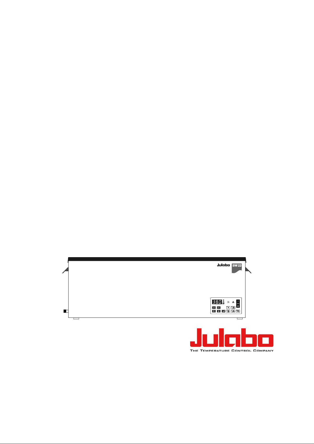
JULABO shaking water baths of the series SW22 and SW23 are ideally suited for
laboratory applications and research in the fields biology, biochemistry, pharmacology, chemistry and general medical technologies. They are likewise suited for
routine laboratory tasks and long-term unattended operation. The JULABO shaking
water bath SW 23 with constant bath liquid circulation, ensures a constant water
temperature with a maximum deviation of 0.02 C .
Julabo shaking water baths feature a stainless steel bath containing heater,
temperature sensor and the overtemperature protection safety element. The shaking
carriage is totally removable.
The units are operated via a water protected foil keypad with integrated mains
switch. Microprocessor technology enables selection and storage of different
temperature values and operating times, and display of them in the LED-MULTIDISPLAY. The self-optimizing electronic PID-control circuit automatically adjusts
the heat supply to the value required by the bath.
The RS232C port permits modern process engineering without additional
interface, directly on-line, from the waterbath to your application equipment.
The overtemperature protection to DIN 12876-1: 2000 is a safety feature with a
fixed safety value of 105 C. It functions independent of the regulator circuit.
2. Operator responsibility – Safety instructions
The products of JULABO ensure safe operation when installed, operated, and
maintained according to common safety regulations. This section explains the potential
dangers that may arise when operating the circulator and also specifies the most
important safety precautions to preclude these dangers as far as possible.
The operator is responsible for the qualification of the personnel operating the units.
The personnel operating the units should be regularly instructed about the dangers
involved with their job activities as well as measures to avert these dangers.
5
Page 6

Operator responsibility – Safety instructions
Make sure all persons tasked with operating, installing, and maintaining the unit have
read and understand the safety information and operating instructions.
When using hazardous materials or materials that could become hazardous, the unit
may be operated only by persons who are absolutely familiar with these materials
and the unit. These persons must be fully aware of possible risks.
If you have any questions concerning the operation of your unit or the information in
this manual, please contact us!
Contact
JULABO USA, Inc.
884 Marcon Boulevard
Allentown, PA 18109
Phone:+1(610) 231-0250
Fax: +1(610) 231-0260
info @ julabo.com
www.julabo.com
Safety recommendations for the operator
You received a product conceived for industrial use. Nevertheless, avoid strikes to
the housing, vibrations, damages to the keypad foil (keys, display) or contamination.
Make sure the product is regularly checked for proper condition. Regularly check (at
least every 2 years) the proper condition of the mandatory, warning, prohibition and
safety labels.
Take care that the mains supply features a low impedance to avoid any negative
affects on the instrument being operated in the same mains.
This unit is designed for operation in a controlled electromagnetic environment. This
means that transmitting devices (e.g. cellular phones) should not be used in the
immediate vicinity. Magnetic radiation may influence other units with components
susceptible to magnetic fields (e.g. a monitor). We recommend to keep a minimum
distance of 1 m.
Permissible ambient temperature: max. 40 °C, min. 5 °C.
Permissible relative air humidity: 50 % (40 °C).
Do not store in an aggressive atmosphere. Protect from contaminations.
Do not expose to sunlight.
Appropriate Operation
Only qualified personnel is authorized to perform configuration, installation,
maintenance and repairs of the water bath.
Routine operation can also be carried out by untrained personnel who should however
be instructed by trained personnel.
Use:
Insufficient ventilation may result in the formation of explosive mixtures. Only use the
unit in well ventilated areas. The unit is not for use in explosive environment.
JULABO water baths have been designed for temperature application to water in a bath
tank.
6
Page 7
Shaking Water Baths
The bath may not be filled with flammable materials. Fire hazard!
Only use non-acid and non corroding bath fluids.
When using hazardous materials or materials that could become hazardous, the
operator must affix the enclosed safety labels to the front of the unit so they are highly
visible:
If this unit is intended for use within the United States of America, all 3 warning labels
must be affixed to the housing of the unit prior to use.
Directions for the positioning of the individual warning labels are enclosed with the
warning labels included in the delivery. Warning labels must be easily visible to users.
1
Warning label W00: Colors: yellow, black
Danger area. Attention! Observe instructions.
2
(operating manual, safety data sheet)
Mandatory label M018: Colors: blue, white
Carefully read the user information prior to beginning
operation.
or
2
Scope: EU
Semi S1-0701 Table A1-2 #9
Carefully read the user information prior to beginning
operation.
3
Scope: USA, NAFTA
Warning label Proposition 65
Particular care and attention is necessary because of the wide operating range.
There are thermal dangers:
Burn, scald, hot steam, hot parts and surfaces that can be touched.
Warning label W26: Colors: yellow, black
Hot surface warning.
(The label is put on by JULABO)
2.1. Disposal
Do not dispose of the unit with household waste!
However, over the long operating period of the unit, disposal rules may change.
Therefore, only qualified personnel should handle the disposal.
7
Page 8

Operator responsibility – Safety instructions
2.2. Technical data
SW22 SW23
Working temperature range °C 25 ... 99,9 25 ... 99,9
with water cooling °C 20 ... 99,9 20 ... 99,9
MULTI-DISPLAY (LED)
Resolution
°C
0.1
0.1
Temperature stability K 0.2 0.02
Computer interface RS232 RS232
Electronic timer h:min 0:01 ... 9:59 0:01 ... 9:59
Heater wattage (at 230 V)
Heater wattage (at 115 V)
kW
kW
2
1
2
1
Adjustable shaking frequency rpm 20 ... 200 20 ... 200
Shaking stroke mm 15 / 25 15 / 25
Bath opening (W x L) cm 50 x 30 50 x 30
Usable bath depth cm 18 18
Filling volume Liter 8 .... 20 8 .... 20
Dimensions W x L x H
(including cover)
cm
cm
70 x 35 x 26
70 x 35 x 43
70 x 35 x 26
70 x 35 x 43
Weight kg 21 22
Ambient temperature °C 5 ... 40 5 ... 40
Mains power connection
V/Hz 207-253V/50-60Hz 207-253V/50-60Hz
(230 V / 50-60 Hz)
Current input (at 230 V) A 10 10
Mains power connection
V/Hz 103-127V/60Hz 103-127V/60Hz
(115 V / 60 Hz)
Current input (at 115 V) A 11 11
All measurements have been carried out at: (DIN 12876)
rated voltage and frequency
ambient temperature: 20°C; operating temperature: 70°C;
bath liquid: water
8
Page 9

Shaking Water Baths
Safety installations according to IEC 61010-2-010:
Excess temperature protection 105 °C - fixed value
Classification according to DIN 12876-1 class I
Alarm indication optical + audible (continuous tone)
Supplementary safety installations
High temperature warning function optical + audible (in intervals)
Low temperature warning function optical + audible (in intervals)
Timer audible (in intervals)
Environmental conditions according to EN 61 010, part 1:
Use only indoor.
Altitude up to 2000 m - normal zero.
Ambient temperature: +5 ... +40 °C (for storage and transportation)
Air humidity:
Max. rel. humidity 80 % for temperatures up to +31 °C,
linear decrease down to 50 % relative humidity at a temperature of +40 °C
Max. mains fluctuation of ±10 % are permissible.
Protection class according to EN 60 529 IP21
The unit corresponds to Class I
Overvoltage category II
Pollution degree 2
Caution:
The unit is not for use in explosive environment.
Standards for interference resistance according to EN 61326-1
This unit is an ISM device classified in Group 1 (using high frequency for internal
purposes) Class A (industrial and commercial range).
9
Page 10
Operating instructions
Operating instructions
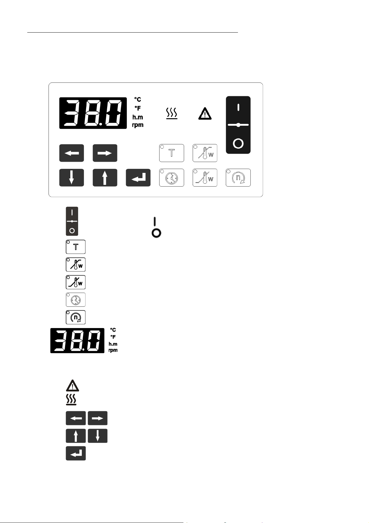
3. Operating controls and functional elements
1
Mains power switch, illuminated
2
3
4
5
6
7
8
Working temperature
High temperature warning limit
Low temperature warning limit
Operating hours indicator key
Nominal value shaking frequency display key
Indication:
MULTI-DISPLAY (LED)
Temperature display optionally in C or F;
time display in h:m and shaking frequency.
The corresponding symbol will illuminate on selection.
Indicator light - Alarm red illuminated
Indicator light - Heating yellow illuminated
Cursors left/right
on
off
9
10
10
Edit keys (increase/decrease setting)
Enter key (store/quitting the audible signal)
Page 11

Shaking Water Baths
8
11
13
14
11 Drainage screw
Connector for liquid level/cooling set (accessory)
12 Mains power cable with plug
13 T 10 A power supply fuses behind side cover
14 RS232C interface
15 Shaking carriage - totally removable
- 8 kg load-carrying capability
16 Surface for placement of items (fixtures)
17 Stroke bar with fastening screw
18 Washers
1715 16
12
17
1
15
11
Page 12
Safety notes for the user
4. Safety notes for the user
4.1. Explanation of safety notes
In addition to the safety warnings listed, warnings are posted
throughout the operating manual. These warnings are designated by
an exclamation mark inside an equilateral triangle. “Warning of a
dangerous situation (Attention! Please follow the documentation).”
The danger is classified using a signal word.
Read and follow these important instructions for averting dangers.
Warning:
Describes a possibly highly dangerous situation. If these instructions
are not followed, serious injury and danger to life could result.
Caution:
Describes a possibly dangerous situation. If this is not avoided, slight
or minor injuries could result. A warning of possible property damage
may also be contained in the text.
Notice:
Describes a possibly harmful situation. If this is not avoided, the
product or anything in its surroundings can be damaged.
4.2. Explanation of other notes
Note!
Draws attention to something special.
4.3. Safety instructions
Follow the safety recommendations to prevent damage to persons or
Important!
Indicates usage tips and other useful information.
property. Further, the valid safety instructions for working places must be
followed.
ConnOnly connect the unit to a power socket with earthing contact
(PE – protective earth)!
The power supply plug serves as a safe disconnecting device from the
line and must always be easily accessible.
Operation is permitted with non-flammable liquids only.
12
Place the instrument on an even surface on a pad made of non-
Page 13

Shaking Water Baths
flammable material.
Do not stay in the area below the unit.
Make sure you read and understand all instructions and safety
precautions listed in this manual before installing or operating your
unit.
Check the filling level of the bath fluid from time to time. The heater
must always be fully covered with the bath fluid!
Never operate the unit without bath fluid in the bath.
Do not drain the bath fluid while it is hot!
Check the temperature of the bath fluid prior to draining (by
switching the unit on for a short moment for example).
Never operate damaged or leaking equipment.
Always turn off the unit and disconnect the mains cable from the
power source before performing any service or maintenance
procedures, or before moving the unit.
Transport the unit with care.
Sudden jolts or drops may cause damage in the interior of the unit.
Always empty the bath before moving the unit.
Never operate equipment with damaged mains power cables.
Observe all warning labels.
Never remove warning labels.
Condensation that could appear in and on other units near the water
bath may result in reduced operating safety.
Be careful when setting up and operating the water bath!
Always turn off the unit and disconnect the mains cable from the
power source before cleaning the unit.
Repairs are to be carried out only by qualified service personnel.
Some parts of the bath cover may become extremely warm during
continuous operation.
When lifting the bath cover, pay attention to hot steam!
Be careful when touching these parts!
Use safety glasses!
WARNING
This product contains chemicals known to the state of California to cause
cancer, birth defects or other reproductive harm.
13
Page 14

Preparations
8
5. Preparations
5.1. Installation
Caution:
The unit is not for use in explosive environment.
>80 mm
17
1
The installation site should meet the following
conditions:
1. The base of the installation site should be level to
ensure proper functioning of the safety features.
2. The laboratory table, for example, should be sturdy
enough, to where the shaking frequency cannot
cause vibration of the table. Consider that the
masses moved may be in the order of several kg.
Keep a wall distance of minimum 80 mm.
Do not cover the ventilation openings on the floor
and rear side of the bath.
Installing and removing the shaking carriage:
Holding screw (17) can be removed without the use
of tools. Retain plastic washers (18) on both sides
of the push rod.
15
Caution:
The shaking frequency may cause a laboratory table to oscillate.
At operation, the vibration may cause items on the table top to fall off
under extreme unfavourable circumstances.
Carefully choose the setup location.
Shaking frequency is adjustable. After readjusting shaking frequency,
always observe other objects near the shaking water bath and
remove them to a different location if necessary.
The shaking carriage can be completely removed.
Samples can be added to the carrier trays while
outside of the bath.
Then put the shaking carriage back into place. Use
the holding screw and plastic washers (18) to screw
the push rod onto the shaking carriage (15).
Tighten the holding screw securely.
14
Page 15

Shaking Water Baths
Caution:
Potential hazards from the samples
Proper use of shaking water baths includes immersion of samples
contained in test tubes, Erlenmeyer flasks, or other containers for the
purpose of controlling their temperature.
We do not know which substances are contained within these vessels.
Many substances are:
inflammable, easily ignited or explosive
hazardous to health
environmentally unsafe
i.e.: dangerous
The user alone is responsible for the handling of these substances!
Always properly seal all sample containers.
Notice:
There is a danger of electrochemical oxidation or corrosion when
using test-tube racks or samples made of non-ferrous metal.
Avoid using these types of racks or samples.
Use only original JULABO test-tube racks.
5.2. Bath liquid
Recommended bath fluids: soft/decalcified water.
Caution:
Poor water quality may result in corrosion in the bath.
The quality of water (tap water) depends on local conditions.
Due to the high concentration of lime, hard water is not suitable for
temperature control because it leads to calcification in the bath.
Ferrous water can cause corrosion - even on stainless steel.
Chloric water can cause pitting corrosion.
Distilled and deionized water is unsuitable. Their special properties
cause corrosion in the bath, even in stainless steel.
JULABO takes no responsibility for damages caused by the selection
of an unsuitable bath fluid.
Please contact JULABO before using other than recommended bath
fluids.
Do not use flammable bath fluids!
15
Page 16

Preparations
5.3. Filling / Draining
Filling:
Maximum filling level: 6 cm below the bath rim
Minimum filling level: 7 cm (level approx. 3 cm above
surface (16) for the placement of items/fixtures)
Note:
The working filling level depends on size and number of
the items (fixtures) to be placed inside.
Fill to minimum level only. Insert the complemented
shaking carriage and correct the filling level (adding or
removing liquid) as required
Use the water bath cover to keep temperature losses to
a minimum:
Lift-up Makrolon
cover see page 18
Draining:
Switch off the shaking water bath with the mains
switch and move the equipment to the table edge.
Place a suitable collecting bucket or tub underneath
the equipment for draining the used liquid.
To drain the liquid open the dainage screw (11) on the
side of the water bath.
After the liquid has been fully drained, securely tighten
the drainage screw (11) again.
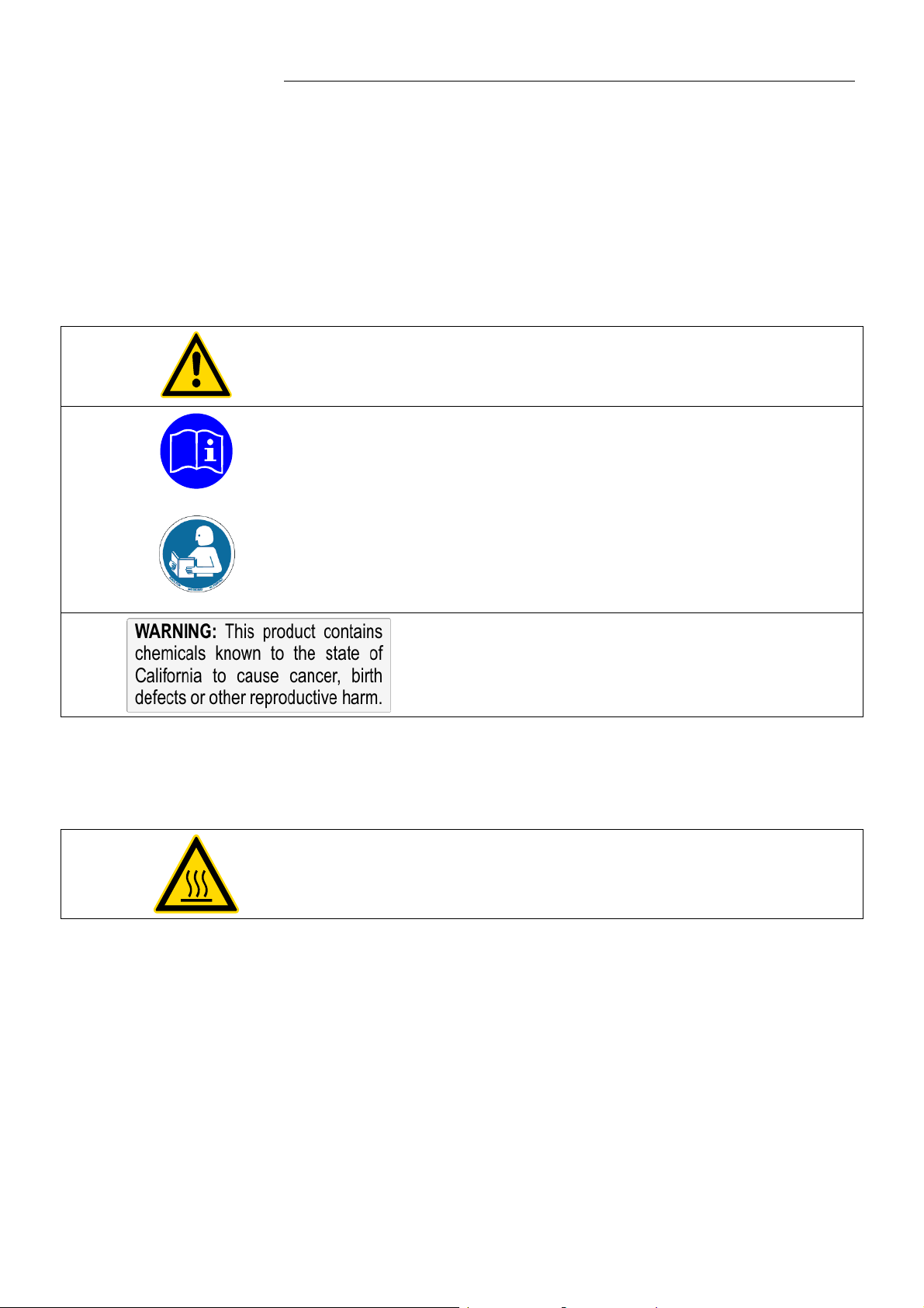
Warning:
There are thermal dangers when opening the bath cover:
Burn, scald, hot steam, hot parts and surfaces that can be touched.
Do not drain the bath fluid while it is hot!
16
Check the temperature of the bath fluid prior to draining
(by switching the unit on for a short moment, for example).
Page 17

5.4. Maintaining a constant water level / Counter cooling
Shaking Water Baths
For cooling tasks near the ambient air temperature the
liquid level/cooling set can be used for counter cooling.
By special pipe routing, cool faucet water is continuously
supplied to the water bath, while at the same time, the
heated water is drained via the overflow connection of
the Level/Cooling set.
A specific water flow rate of 100 ml/minute is sufficient
to compensate for the characteristic temperature.
Caution:
Securely attach all tubing to prevent slipping.
Observe the laws and regulations of the water distribution company valid
in the location where the unit is operated.
Use of the liquid level/cooling set for a continuous supply
of faucet water:
1. to keep the water level constant, especially for
applications up to the boiling point (supply of faucet
water only in the amount of evaporation losses).
2. for countercooling of cooling tasks near the ambient
surrounding temperature (cool faucet water is
continuously supplied to the water bath, while at the
same time, the heated water is drained via the
overflow connection of the liquid level/cooling set).
11 drainage screw on water bath
20 compensation reservoir
21 connecting sleeve
22 supply/drainage sleeve
23 overflow sleeve
24 adaptor screw for constant liquid level function
25 adaptor screw assy. for countercooling function and
simultaneous constant liquid level control
26 adjuster screw for filling level adjustment
17
Page 18

Preparations
5.5. Accessories
Bath covers
Recommendation:
Use the water bath cover to keep temperature losses to a
minimum. This is especially important for working
temperatures above 60 C.
Order No. Description
8 970 288 Lift-up Makrolon cover (to +80 °C)
8 970 268 Lift-up stainless steel cover (to +100 °C)
Cooling installation / continous water supply
Recommendation:
For continious water supply and counter-cooling
Order No. Description
8 970 415 Liquid level/cooling set
8 970 416 Cooling coil
18
Page 19

6. Operating procedures
6.1. Power connection
Caution:
Only connect the unit to a power socket with earthing contact (PE –
protective earth)!
The power supply plug serves as safe disconnecting device from the
line and must be always easily accessible.
Never operate equipment with damaged mains power cables.
Regularly check the mains power cables for material defects (e.g. for
cracks).
We disclaim all liability for damage caused by incorrect line voltages!
Check to make sure that the line voltage matches the supply
voltage specified on the identification plate.
Shaking Water Baths
7. Switching on
The unit performs a self-test. All segments of the 4-digit
Adjustable parameters and temperature values are
When the shaking water bath is operating under remote
Switching on:
Turn on the mains power switch.
MULTI-DISPLAY (LED) and all indicator lights will
illuminate.
Then the software version (example: n 1.3) appears.
Together with the display of the water bath temperature the
operating state is also displayed.
(Example: 18.6 C)
The monitor lamp
operation (on).
Notes:
retained and the electronic timer is reset to zero when the
equipment is switched off.
control at the time of switchoff (connected to PC via
RS-232 interface connection), the MULTI-DISPLAY (LED)
will display the message „OFF“.
(see chapter 8.5. Setup for remote control )
illuminates when the heater is in
If shaking operation is not desired it can be switched off at
menu level. Select the menu level and activate the option
SA (see page 24).
19
Page 20

Switching on
7.1. Setting the temperature
Display and adjustment of the working temperature:
Press the setpoint key .
The indicator light blinks and the value previously set
appears on the MULTI-DISPLAY (LED).
(example: 25.0 °C).
If no further key is pressed the display will return to show
the actual bath temperature after approx. 8 seconds.
Use the cursor keys to move left or right on the
display until the numeral you wish to change is blinking.
Use the increase/decrease arrows to change
the selected numeral (0, 1, 2, 3, ... 9).
Press enter to store the selected value
(example: 38.0 °C).
The working temperature is maintained constant after a short
heat-up time (e. g. 38.0 °C).
Notice:
When the working temperature is higher than 50 °C, it might happen that
due to strong production of steam there is considerable dripping on the
inside of the lift-up Makrolon cover. Some drops may fall directly into the
material to be tempered.
Always properly seal all sample containers.
7.2. Warning functions or temperature limit
More protection for your samples in the bath!
......
As soon as the actual temperature leaves one of the preadjusted limits, this status is evaluated.
The high- and low-temperature limit can be evaluated in two
ways (see page 29).
1. As pure warning function with an acoustic signal in regular
intervals. (Signal - Pause)
2. As temperature limit by switching-off the heating and
alarm.
20
Page 21

Shaking Water Baths
Display and adjustment of over-/undertemperature:
Press the key
(example: 41 °C)
(example: 35 °C).
or
The indicator light blinks and the value previously set
appears on the MULTI-DISPLAY (LED).
If no further key is pressed the display will return to show
the actual bath temperature after approx. 8 seconds.
Use the cursor keys to move left or right on the
display until the numeral you wish to change is blinking.
Use the increase/decrease arrows to change
the selected numeral (0, 1, 2, 3, ... 9).
Press enter to store the selected value
C°
41
38
35
20
t
Note:
The warning functions will be activated only after the bath
temperature has remained for at least 3 seconds within the
adjusted threshold values after the equipment is switched on.
21
Page 22

Switching on
7.3. Adjustment of the shaking frequency
The shaking frequency is adjustable between 20...200 rpm. If
shaking operation is not desired it can be switched off at
menu level. Select the menu level and activate the option SA
(see page 24)
Display and adjustment of the shaking frequency
Press the key .
The indicator light blinks and the value previously set
appears on the MULTI-DISPLAY (LED).
(example: 120 rpm).
If no further key is pressed the display will return to show
the actual bath temperature after approx. 8 seconds.
Use the cursor keys to move left or right on the
display until the numeral you wish to change is blinking.
Use the increase/decrease arrows to change
the selected numeral (0, 1, 2, 3, ... 9).
Press enter to store the selected value
Caution:
Danger of injury. Samples may fall over.
Do NOT reach in the shaking carriage during shaking operation.
Danger of injury!
Always use carrier trays in order to prevent sample containers from
falling over.
22
Page 23

7.4. Electronic timer
Shaking Water Baths
..
The electronic timer enables adjustment of the operating
time up to a maximum of 9 hours and 59 minutes.
Countdown then commences to zero, at which time an
acoustical time signal will be issued in intervals
(double signal - pause).
- the equipment will not be switched off -
Display and adjustment of the operating time:
Press the key .
The indicator light blinks and and the MULTI-DISPLAY
(LED) will display the remaining operating time (example:
4.28 h:m).
If no further key is pressed the display will return to show
the actual bath temperature after approx. 8 seconds.
Use the cursor keys to move left or right on the
MULTI-DISPLAY (LED) until the numeral you wish to
change is blinking.
Use the edit keys to increase or decrease the
numeral value (0, 1, 2, 3, ... 9).
Press enter to store the value when the countdown
will commence. During that time the monitor lamp (control
lamp) will remain permanently illuminated.
=
When the operating time is expired an acoustical time signal
is issued in intervals.
Cancellation of the time signal:
Press enter
Notes:
Following switch-on of the equipment and after a power
failure, the timer will show 0:00 h:m.
When the equipment is operating remotely controlled the
timer is rendered inoperative.
to silence the time signal.
23
Page 24

Menu functions
8. Menu functions
Adjustment of parameters which, in most instances, need
only be adjusted once, are performed on the water bath at
menu level.
1. Shaking operation On/Off
2. Circulator pump On/Off
(Only shaking water bath SW23).
3. MULTI-DISPLAY temperature display in C or F
4. ATC (absolute temperature calibration)
5. Switchover to remote controlled operation
6. Adjustment of interface parameters
7. Adjustment of the high and low temperature limit.
Choice between pure warning function or a
temperature limit by switching off the heating.
8.1. Shaking operation On/Off
Selecting/exiting the menu level.
Simultaneously
press the cursor key
1. Press the cursor key
time.
2. Use the cursor keys
„shaking operation“
example: „SA1“ = shaking frequency ON.
3. Select the alternative state with the edit keys
and confirm the selection with the ENTER key
The display now shows „SA0“ = shaking frequency OFF.
and enter .
and enter at the same
to select the menu option
.
24
Page 25

8.2. Circulator pump on/off
Shaking Water Baths
Only shaking water bath SW23 feature a circulator pump.
The pump can be set to on and off at the menu level.
At working temperatures > 80 C the pump will switch off
automatically
1. Press
2. Use the cursor keys
PUMP
(example: „Pu1“ = Pump ON )
and at the same time.
to select the menu option
3. Select the alternative state with the edit keys
and confirm the selection with the ENTER key
(example: „Pu0“ = Pump OFF).
4. Press
and at the same time.
8.3. Temperature indication in °C or °F
The working temperature can be displayed in the MULTIDISPLAY (LED) in C or F as desired.
1. Press
and at the same time.
2. Use the cursor keys
„temperature display“
(example: „t C“ = temperature display in C).
3. Select the alternative state with the edit keys
and confirm the selection with the ENTER key
display now shows „t F“ = temperature display in F.
4. Press
and at the same time.
Switchover to the selected display mode takes place
automatically upon leaving the menu level.
to select the menu option
. The
25
Page 26

Menu functions
8.4. ATC - Absolute Temperature Calibration
ATC serves to compensate a temperature difference that
might occur between circulator and a defined measuring point
Internal sensor (T
)
F
in the bath tank because of physical properties.
The difference temperature is determined (T= T
and stored as correcting factor (example T = -0.2 °C).
Measuring point(T
)
M
M
- T
)
T
Measuring point
1. Press the cursor key
and enter at the same
time.
2. Use the cursor keys
to select the menu option
„At0“.
3. With the edit keys
enter
.
select "At1" and then press
Enter the corrective value.
4. Using the cursor keys
then press enter
5. Press
set the correcting factor (example -0.20 °C) and
.
and at the same time.
and the edit keys
The temperature on the measuring point rises to a
temperature of 37.0 °C and is indicated on the
MULTI-DISPLAY (LED).
26
The ATC function stays activated until resetting to 00.0 °C.
Recommendation:
Use a calibrated temperature measuring instrument.
Page 27

8.5. Setup for remote control
Shaking Water Baths
If the shaking water bath is to be remotely controlled or
monitored, the parameter of the menu option REMOTE must
be changed and set from 0 to 1.
REMOTE 0 = Keypad control
1 = Remote control via RS232 interface
1. Press
and at the same time.
2. Use the cursor keys
to select the menu option
REMOTE
(display „r 0“).
3. Select the alternative state with the edit keys
and confirm the selection with the ENTER key
(display „r 1“).
The shaking water bath will switch to the REMOTE
„STOP“ condition and the MULTI-DISPLAY will show the
message „OFF“.
4. Press
and at the same time.
27
Page 28

Menu functions
8.6. Adjusting interface parameters
Correct data transmission takes place only when the interface
parameters of PC and water bath are identical.
1. Press
2. Use the cursor keys
and at the same time.
to select the desired menu
option
(BAUDRATE, PARITY, HANDSHAKE).
3. Select the alternative state with the edit keys
and confirm the selection with the ENTER key
4. Press
and at the same time.
.
Adjustable interface parameters
BAUDRATE 48 = 4800 bauds *
96 = 9600 bauds
PARITY 0 = no parity
1 = odd parity
2 = even parity *
HANDSHAKE
0 = Protocol Xon/Xoff (software handshake)
1 = without handshake *
Data bits = 7; Stop bit = 1 *
(*Factory setting)
28
Like all parameters which can be entered through the keypad,
interface parameters are stored in memory even after the
circulator is turned off.
Page 29

8.7. Evaluation of the temperature limits
Shaking Water Baths
The high- and low-temperature limit can be adjusted in two
ways (see page 20)
1. As pure warning function with an acoustic warning signal in
regular intervals.
Adjustment „Li 0“ – factory adjustment
2. As temperature limit by switching-off the heating.
Adustment „Li 1“
The alarm is indicated by optical and audible signals
(continuous tone) and on the MULTI-DISPLAY (LED)
appears the error message "Error 01".
1. Press
2. Use the cursor keys
Limit. (example: „Li 0“).
and at the same time.
to select the menu option
3. Select the alternative state with the edit keys
and confirm the selection with the ENTER key
(display „Li 1“).
4. Press
and at the same time.
9. Safety installation (with shutdown function)
(excess temperature protection)
These safety installations is independent of the control circuit.
When the temperature of the bath liquid has reached the
safety temperature, a complete shutdown of the heater and
pump (only CW-models) is effected.
The alarm is indicated by optical and audible signals
(continuous tone) and on the MULTI-DISPLAY (LED) appears
the error message "Error 01".
29
Page 30

Troubleshooting guide / Error messages
10. Troubleshooting guide / Error messages
+
Whenever the microprocessor electronics registers a failure, a
complete shutdown of the heater and circulation pump (only
CW-models) is performed. The alarm light "
a continuous signal tone sounds.
Cause:
The waterbath is operated without bath liquid, or the liquid
level is insufficient
or
The adjusted temperature limit was exceeded or the
temperature fell below the limit.
Remedy: Replenish the bath tank with the bath liquid.
Control the adjustment of the temperature limit.
Get to safety the samples.
" illuminates and
The wires of the working temperature sensor are interrupted
or short-circuited.
other errors
Heating circuit interrupted.
30
Short-circuit of triac.
Short-circuit in alarm relay.
After eliminating the malfunction, press the mains power switch
2
1
off and on again to cancel the alarm state.
If the unit cannot be returned to operation, contact an
authorized JULABO service station.
Page 31

Shaking Water Baths
Warning:
Danger of electric shock!
The exchanging of the fuses are to be carried out only by
qualified service personnel.
Before exchanging the fuses, turn off the mains power switch and
disconnect the power plug from the mains socket!
Only use fine fuses with a nominal value as specified.
Disturbances that are not indicated.
Mains fuses
Pull the mains plug from the power outlet before opening
the equipment!
The mains fuses are located behind side plate (13).
The side plate is fastend to the casing with 6 screws .
(Fine fuse T 10.0 A, dia. 5 x 20 mm)
Sicherungen
Fuses
Fusibles secteur
Pump motor overload protection
The pump motor is protected against overloading. After a
short cooling interval, the motor will automatically start
running.
31
Page 32

Troubleshooting guide / Error messages
10.1. Acoustical signals and their differentiation
Three different signals are generated by the sound
generator as follows:
- an alarm signal
- a warning signal
- a time signal
The signals can easily be recognized and differentiated, even
from a good distance. Required actions can be initiated
immediately.
The Alarm signal is a continuous sound signal.
Heater and circulator pump (SW23 only) are completely and
permanently switched off.
(see page 29)
......
..
The warning signal is issued at regular intervals
(signal - pause - signal - pause).
The actual bath temperature is higher than the set
overtemperature value or lower than the set
undertemperature value
(see page 20)
The time signal is issued in the intervals
(double signal - pause - double signal - pause).
Countdown of the adjusted operating time commences to
zero, after which a time signal is issued at intervals
(see page 23)
32
Page 33

11. Electrical connection
Shaking Water Baths
RS232C serial interface
This port can be used to connect a computer with an RS232C
cable for remote control of the waterbath.
1
2
3
2
Pin assignment:
Pin 1 RxD Receive Data
Pin 2 TxD Transmit Data
Pin 3 0 VD Signal GND
3
1
Use shielded cables only.
Accessories:
RS-232 interface connecting cable, terminated with 3-pin
Cinch plug and 9 hole subD socket. Length: 3.0 m.
Order No. 8 980 075
33
Page 34

Remote control
12. Remote control
12.1. Communication with a PC or a superordinated data system
A suitable terminal program for communicating with a PC is:
Terminal.EXE (included with MS-Windows).
If the waterbath is put into remote control mode via the menu
level, the display will read "OFF" = REMOTE STOP. (see
page 27).
The waterbath is now operated via the computer.
In general, the computer (master) sends commands to the
waterbath(slave). The waterbath sends data (including error
messages) only when the computer asks for it.
A transfer sequence consists of:
command
space ; Hex: 20)
parameter (the character separating decimals in a
group is the period)
end of file (; Hex: 0D)
The commands are divided into in or out commands.
in commands: asking for parameters to be displayed
out commands: setting parameters
The out commands are valid only in remote control mode.
34
Examples:
Command to set the working temperature T to 55.5 °C:
out_sp_00 55.5
Command to ask for the working temperature T:
in_sp_00
Response from the shaking water bath:
55.5
Page 35

Shaking Water Baths
12.2. List of commands
Command Parameter Response of the shaking water bath
version none Number of software version(V X.xx)
status none Status message, error message (see below)
out_mode_05 0 STOP - returns the water bath to the „OFF“ state
out_mode_05 1 START - water bath is switched to the operating state
out_mode_08 0 Circulator pump „OFF“
out_mode_08 1 Circulator pump „ON“
out_mode_09 0 Shaking operation drive motor „OFF“
out_mode_09 1 Shaking operation drive motor „ON“
out_sp_00 xxx.x Set working temperature„T“
out_sp_02 xxx.x
Set high temperature warning limit
out_sp_03 xxx.x
Set low temperature warning limit
out_sp_16 xxx.x Set shaking frequency
in_sp_00 none Ask for working temperature „T“
in_sp_02 none
Ask for high temperature warning limit
in_sp_03 none
Ask for low temperature warning limit
in_sp_16 kein Ask for shaking frequency
in_pv_00 none Ask for actual bath temperature
in_pv_01 none Ask for the heater wattage being used
35
Page 36

Remote control
12.3. Status messages
Message Description
01 MANUAL START Waterbath in keypad control mode.
02 REMOTE STOP Waterbath in „OFF“ state
03 REMOTE START Waterbath in remote control mode
12.4. Error messages
Message Description
-01 TEMP / LEVEL ALARM Safety temperature or low liquid level alarm
-03 EXCESS TEMPERATURE
High temperature warning „
„.
WARNING
-04 LOW TEMPERATURE
WARNING
-05 TEMPERATURE
Low temperature warning „
Error in measuring system
„.
MEASUREMENT ALARM
-07 I2C-BUS WRITE ERROR
-07 I2C-BUS READ ERROR
Internal error
-07 I2C-BUS READ/WRITE ERROR
-08 INVALID COMMAND
Invalid command
-10 VALUE TOO SMALL
Entered value too small
-11 VALUE TOO LARGE
Entered value too large
-12 WARNING : VALUE EXCEEDS
TEMPERATURE LIMITS
-13 COMMAND NOT ALLOWED IN
CURRENT OPERATING MODE
36
Value lies outside the adjusted range for the
high and low temperature warning limits. But
value is stored.
Invalid command in current operating mode
Page 37

13. Cleaning / repairing the unit
Caution:
Improper maintenance or repair can result in electric shock or damage to
Cleaning:
the unit.
Repairs and any other work are to be carried out only by qualified
service personnel authorized by JULABO.
Always turn off the unit and disconnect the mains cable from the
power source before performing any service or maintenance
procedures, or before moving the unit.
Prevent humidity from entering into the water bath.
Do not use alcohol-based or solvent-based cleaning agents.
These cleaning agents will result in damage and cracks in the
Makrolon cover.
For cleaning the bath tank and the immersed parts of the
water bath, use low surface tension water (e.g., soap suds).
Clean the outside of the unit using a wet cloth and low surface
tension water.
The JULABO Skaking Water Baths are designed for
continuous operation under normal conditions. Periodic
maintenance is not required.
Shaking Water Baths
Repairs:
Returning a unit:
The tank should be filled only with a bath fluid recommended
by JULABO. To avoid contamination, it is essential to change
the bath fluid from time to time.
Before asking for a service technician or returning a JULABO
instrument for repair, please contact an authorized JULABO
service station.
When returning the unit:
Clean the unit and, if necessary, decontaminate the unit in
order to avoid endangering service personnel.
Attach a short fault description.
During transport the unit has to stand upright. Mark the
packing correspondingly.
When returning a unit, take care of careful and adequate
packing.
JULABO is not responsible for damages that might occur
from insufficient packing.
JULABO reserves the right to carry out technical modifications
with repairs for providing improved performance of a unit.
37
Page 38

WARRANTY PROVISIONS
14. WARRANTY PROVISIONS
The following Warranty Provisions shall apply to products sold in North America by Julabo (“Seller”) to the entity
shown as buyer (“Buyer”) on Seller’s invoice.
1. Initial Warranty. Upon Seller’s receipt of payment in full for the products and subject to Buyer’s
compliance with the terms of sale and any other agreement with Seller relating to the products, Seller warrants to
the Buyer that the products manufactured by the Seller are free from defects in material and workmanship for a
period not to exceed two (2) years or ten thousand (10,000) hours of operation, whichever comes first, from the
date the product is shipped by Seller to Buyer (the “Initial Warranty”).
2. EXCLUSION OF ALL OTHER EXPRESS WARRANTIES; EXCLUSION OF ALL IMPLIED
WARRANTIES. OTHER THAN THE INITIAL WARRANTY, NO OTHER EXPRESS WARRANTIES ARE MADE.
ALL IMPLIED WARRANTIES OF EVERY TYPE AND KIND, INCLUDING BUT NOT LIMITED TO ANY IMPLIED
WARRANTY OF MERCHANTABILITY OR FITNESS FOR A PARTICULAR PURPOSE OR USE, ARE
EXCLUDED IN ALL RESPECTS AND FOR ALL PURPOSES. SELLER DISCLAIMS AND MAKES NO IMPLIED
WARRANTIES WHATSOEVER.
3. Exclusions. The Initial Warranty does not include damage to the product resulting from accident,
misuse, improper installation or operation, unauthorized or improper repair, replacement or alteration (including but
not limited to repairs, replacements, or alterations made or performed by persons other than Seller’s employees or
authorized representatives), failure to provide or use of improper maintenance, unreasonable use or abuse of the
product, or failure to follow written installation or operating instructions. Buyer must return the product’s record of
purchase to the Seller or one of Seller’s authorized representatives within thirty (30) days of the date the product is
shipped by Seller to Buyer in order to make a claim under the Initial Warranty. Notwithstanding anything contained
herein to the contrary, all glassware, including but not limited to reference thermometers, are expressly excluded
from the Initial Warranty.
4. Buyer’s sole remedies; Limitations on Seller’s Liability. Buyer’s sole and exclusive remedy
under the Initial Warranty is strictly limited, in Seller’s sole discretion, to either: (i) repairing defective parts; or (ii)
replacing defective parts. In either case, the warranty period for the product receiving a repaired or replaced part
pursuant to the terms of the Initial Warranty shall not be extended. All repairs or replacements performed by Seller
pursuant to these Warranty Provisions shall be performed at Seller’s facility in Allentown, Pennsylvania, U.S.A. or
Vista, California, U.S.A or at the facility of an authorized representative of Seller, which location shall be determined
by Seller in its sole discretion; provided, however, that Seller may, in its sole discretion perform such repairs or
replacements at Buyer’s facility in which case Buyer shall pay Seller’s travel, living and related expenses incurred
by Seller in performing the repairs or replacements at Buyer’s facility. As a condition precedent to Seller’s
obligation to repair or replace a product part under the Initial Warranty, Buyer shall (i) promptly notify Seller in
writing of any such defect; (ii) shall have returned the product’s record of purchase to Seller or to one of Seller’s
authorized representatives within thirty (30) days of the date the product is delivered to Buyer; and (iii) assist Seller
in all respects in its attempts to determine the legitimacy and basis of any claims made by or on behalf of Buyer
including but not limited to providing Seller with access to the product to check operating conditions. If Buyer does
not provide such written notice to Seller within the Initial Warranty period or fails to return the product’s record of
38
Page 39

Shaking Water Baths
purchase as set forth above, Seller shall have no further liability or obligation to Buyer therefore. In no event shall
Seller’s liability under the Initial Warranty exceed the original purchase price of the product which is the subject of
the alleged defect.
5. THE REMEDIES PROVIDED IN THE INITIAL WARRANTY ARE THE SOLE AND EXCLUSIVE
REMEDIES AVAILABLE TO THE BUYER. NOTWITHSTANDING ANYTHING TO THE CONTRARY CONTAINED
HEREIN, AND EVEN IF THE SOLE AND EXCLUSIVE REMEDIES FAIL OF THEIR ESSENTIAL PURPOSE FOR
ANY REASON WHATSOEVER, IN NO EVENT SHALL SELLER BE LIABLE FOR BUYER’S MANUFACTURING
COSTS, LOST PROFITS, GOODWILL, OR ANY OTHER SPECIAL, INDIRECT, PUNITIVE, INCIDENTAL OR
CONSEQUENTIAL DAMAGES TO BUYER OR ANY THIRD PARTY AND ALL SUCH DAMAGES ARE HEREBY
DISCLAIMED.
6. Assignment. Buyer shall not assign any of its rights or obligations hereunder without the prior written
approval of Seller; provided, however, that if Buyer is a distributor of Seller, the rights and obligations of Buyer under
these Warranty Provisions shall inure to the benefit of and be binding upon Buyer’s customers who provide the
product’s proof of purchase to Seller pursuant to the terms set forth herein. Seller may assign any or all of its rights or
obligations hereunder without Buyer’s prior consent.
7. Governing Law. The Warranty Provisio ns and all questions relating to their validity, interpretation,
performance, and enforcement shall be construed in accordance with, and shall be governed by, the substantive laws
of the Commonwealth of Pennsylvania without regard to its principles of conflicts of law.
8. Waiver. Any failure of the part of Seller to insist on strict compliance with the Warranty Provisions shall
no way constitute a waiver of such right. No claim or rights arising out of a breach of the Warran t y P r ov i s io n s by Buyer
may be discharged in whole or in part by a waiver of the claim or right, unless the waiver is in writing signed by an
authorized representative of Seller. Seller’s waiver or acceptance of any breach by Buyer of any provisions of the
Warran ty Pr ovisio ns shall not constitute a waiver of or an excuse for nonperformance as to any other provision of the
Warranty Provisions nor as to any prior or subsequent breach of the same provision.
9. Freight
Seller.Seller will arrange and pay for shipping and handling for the return of the unit to the Buyer.
. Buyer will arrange and pay for shipping and handling charges for the unit to be returned to the
39
 Loading...