

Page 1
Original Operating Manual
1.951.3727-V2 en 01/14
High Temperature Circulator
HT60-M2 HT60-M3
C.U.-cooling unit
JULABO GmbH
77960 Seelbach / Germany Tel. +49 (0) 7823 / 51-0 Fax +49 (0) 7823 / 24 91 info@julabo.de www.julabo.de
19513727-V2.docx Print date: 13.01.14
Forte HT with cooling unit
Page 2

Operating manual
Congratulations!
You have made an excellent choice.
JULABO thanks you for the tr ust y ou hav e plac ed in us.
This operati ng manual has been designed t o help you gain an understanding of the operation and possible
applicati ons of our ci rculators. For optimal utili z ation of all functions, we recommend that you thoroughly study
this manual prior to beginning operation.
The JULABO Quality Management System
Temperature cont rol devices f or research and indu stry are dev eloped, pr oduced, and
distribut ed ac c or ding to the requirements of ISO 9001 and ISO 14001. Certificate
Registrati on No. 01 100044846
Unpacking and inspecting
Unpack the instrument and accessories and inspect them for possible transport damage. Dam age shoul d be
reported to the responsible carrier, rail way, or postal authority, and a damage report should be requested. These
instructions must be followed fully for us to guarantee our full support of your claim for protecting against loss
from concealed damage. The form required for filing such a claim will be provided by the carrier.
Printed in Germany Changes without prior notification reserved
Important: keep operating manual for future use
2
Page 3

TABLE OF CONTENTS
HT60-M2 / HT60-M3
OPERATING MANUAL .................................................................................................................... 5
1. INTENDED USE ....................................................................................................................... 5
1.1. Description ................................................................................................................... 5
2. OPERATOR RESPONSIBILITY – SAFETY INSTRUCTIONS .................................................... 6
2.1. Disposal ....................................................................................................................... 7
2.2. EC Conformity .............................................................................................................. 8
2.3. Warranty conditions .................................................................................................... 12
2.4. Technical specifications .............................................................................................. 13
2.5. Cooling water connection ............................................................................................ 16
3. OPERATING CONTROLS AND FUNCTIONAL ELEMENTS ................................................... 17
M2 or M3 – control electronic .................................................................................................. 17
HT60 High Temperatur e Cir c ulator with C.U.-cooling unit (option) ........................................... 20
4. SAFETY NOTES FOR THE USER .......................................................................................... 22
4.1. Explanation of safety notes ......................................................................................... 22
4.2. Explanation of other notes .......................................................................................... 22
4.3. Safety instructions ...................................................................................................... 22
5. PREPARATIONS .................................................................................................................... 25
5.1. Setup .......................................................................................................................... 25
5.2. Installation .................................................................................................................. 26
5.3. Bath fluids .................................................................................................................. 28
5.4. Tubing ........................................................................................................................ 29
5.5. Power connection ....................................................................................................... 30
5.6. Filling / draining .......................................................................................................... 30
5.7. Degasifying................................................................................................................. 32
5.8. Countercooling ........................................................................................................... 34
6. OPERATING PROCEDURES ................................................................................................. 35
6.1. Switching on / Selecting the language ......................................................................... 35
7. MANUAL OPERATION ........................................................................................................... 36
7.1. Start - Stop ................................................................................................................. 36
7.2. Setting the temperatures ............................................................................................. 36
7.3. Warning functions ....................................................................................................... 37
7.4. Setting the safet y tem per ature (with shutdown function) .............................................. 38
7.5. Internal / external c ontrol ............................................................................................ 39
8. MENU FUNCTIONS ................................................................................................................ 40
8.1. Configuration .............................................................................................................. 41
8.2. Control parameters ..................................................................................................... 44
8.3. Start of a profile .......................................................................................................... 47
8.3.1. I nterrupting a profile ................................................................................................. 49
8.4. Integrated progr ammer ............................................................................................... 50
8.5. Analog input s/outputs ................................................................................................. 53
8.6. Limits .......................................................................................................................... 56
3
Page 4

Operating manual
8.7.
Interface ..................................................................................................................... 57
8.8. Sensors ...................................................................................................................... 57
9. TROUBLES HOOT IN G GU IDE / ERROR MESSAGES ............................................................ 59
10. ELECTRICAL CONNECTIONS ............................................................................................... 61
11. REMOTE CONTROL .............................................................................................................. 63
11.1. S etup for remote control ............................................................................................. 63
11.2. Com munication with a PC or a superordinat ed data system ........................................ 64
11.3. List of commands........................................................................................................ 65
11.4. Status messages / error messages ............................................................................. 68
12. CLEANING / REPAIRING THE UNIT ...................................................................................... 70
4
Page 5

HT60-M2 / HT60-M3
Operating manual
1. Intended use
The High Temperatur e Cir c ulators HT60-M2 and HT60-M3 are to be employed especially for closed tempering
circuits in the laboratory, the technical institution or the production, like e.g. for distillation plants, reaction vessels,
autoclaves, injection moulding tools.
JULABO circulators are not suitable for direct t em per ature c ontrol of foods, semi-luxury foods
and tobacco, or pharm ac eutical and medical products. Dir ec t t em per ature control means
unprotected cont ac t of the object with the bath medium (bath fl uid) .
1.1. Description
The structure of the High Temperature Circulator HT60 is sub-div ided in three zones:
• The cold zone (on t op) wit h the electronics for controlling and monitoring, the tem per ature c ontrol and the
pump motor.
• The cooling z one with the cooling coil, the fl oat f or the lev el indication, a temperature sensor for monitoring
the temperatur e, t he c onnec tion for inert-gas, the connecti on for the expansion vessel as well as an overfl ow
nozzle. At thi s place t he temper ature monitoring is independant from the other safety devices.
• The heati ng zone (down) with the heating element , t he pum p, t he temper ature sensors and the flow nozzl e
The C.U.-cooling unit can be installed firmly and fulfills two tasks.
• The temperature of the tempering liquid in the cooling zone is supervised. If it is necessary the cooling water
is led through the integr ated cooling coil in order to reduce the temperature (without C.U.-cooling unit the
cooling coil c an be connect ed dir ec tly to the cooling water).
• With a separate cooling circuit through the C.U.-cooling unit a rapid cooli ng of t he temper ing liquid becomes
possible.
The M2 or M3 control electronics is connected to the HT60-circulator via a control cable.
• The local oper ation of the control electronics M2 / M3 is effected via a splash-water protected keypad. The
Microprocessor technology allows to set three different temperatur e v alues, to store and to indicate them via
the digi tal display LCD – the worki ng temperature and the values for t he excess and lower t em per ature
warning functi ons.
• With the integrated programmer the instructions for setpoint and time for six different temperature pr ofiles
can be stored and call ed in.
• Via an analog i nterface REG+E-PROG an analog programmer can be connec ted for the setpoint.
• At the same tim e this interface is provided with three analog outputs for the recorder. For the best resol ution
the output settings can be adjusted via the menu delete surfac e - should just be Menu.
The remote control via the digital RS232/RS485 int erface according to NAMUR allows the m ost m oder n
process technology without additional interface.
• The excess temper ature protection i s a safety equi pm ent which does not depend on t he control circle. Its
safety value is shown and can be adjusted by the MULTI-DISPLAY (LED).
• The level of liquid is acquired in the cooling z one, indicated to the control el ectr onic s via the control cable.
There they are made vi sibl e by an 8-grade level indication.
5
Page 6

Operator responsibi lity – Safety instructions
2. Operator responsibility – Safety instructions
The products of JULABO ensure safe operation when installed, operated, and mai ntained according to common
safety regulati ons. This section explains the pot ential dangers that m ay arise when operating the circulator and
also specifies the m ost im por tant safety precautions to precl ude these dangers as far as possible.
The operator is responsible for the qualific ation of the personnel operating the units.
The personnel operating the units should be regul arl y instruct ed about the dangers inv olv ed with their job
activiti es as well as m easures to avert these dangers.
Make sure all persons tasked with operating, install ing, and maintaining the unit hav e r ead and under stand
the safety information and oper ating instructions.
When using hazardous mat eri als or materials that could become hazardous, the circ ulator may be operated
only by persons who are absolutel y familiar with these materi als and the ci r c ulator. These persons must be
fully aware of p ossible r isks.
If you have any questions concerning the operation of your unit or the information in this manual, please cont ac t
us!
Contact:
Safety instructions for the operator:
Avoid strikes to t he housi ng, vibrations, damage to the operating-element panel ( k ey pad, display), and
contamination.
Make sure the product is checked for proper condition regular ly (depending on the conditions of use).
Regularly check ( at least every 2 years) the proper condition of the mandatory, warning, pr ohibition and
safety labels.
Make sure that the mains power supply has l ow im pedanc e to avoid any negativ e eff ects on the instr um ents
being operated on the same mains.
This unit is designed f or oper ation in a controlled electromagnetic environment. This means that transmitti ng
devices (e.g., cellular phones) should not be used in the immediate vicinity.
Magnetic radiation may affect other devic es with c om ponents sen si tive to magnetic fields (e.g., monitors).
We recommend maintai ning a mi nim um distanc e of 1 m.
Permissible am bient temperature: max. 40 °C, min. 5 °C.
Permissible r elative humidity: 50% (40 °C).
Do not store the unit in an aggressive atmosphere. Protect t he unit f r om cont ami nation.
Do not expose the unit to sunlight.
JULABO GmbH
Eisenbahnstraße 45
77960 Seelbach / Germany
Tel. +49 (0) 7823 / 51-0
Fax +49 (0) 7823 / 24 91 www.julabo.de
info@julabo.de
Appropriate operation
Only qualified per sonnel is authorized to confi gur e, install, maintain, or repair the circulator.
Persons who operate the cir c ulator must be trained in the partic ular tasks by qualified personnel. The
summarized user guidance ( short manual) and the specification table with inform ation on individual parameters
are sufficient for this.
6
Page 7
HT60-M2 / HT60-M3
is not permitted!
Use
The bath can be filled with flammable materials. Fire hazard!
There might be chemic al danger s dependi ng on the bath medium used.
Observe all warnings f or the used m aterials (bath fluids) and t he r espect ive instructions (safety data sheets).
Insufficient ventilation may result in the formation of explosive mixtures. Only use the unit in well ventilated
areas.
Only use recommended m aterials (bath fluids). Only use non-acid and non c or r oding materials.
When using hazardous mat eri als or materials that could become hazardous, the operator must affix the
enclosed safety labels (1 + 2) to the front of the unit so they are highly visible:
1
2
or
2
Particular care and at tention is necessary because of the wide operat ing range.
There are thermal danger s: B ur n, scald, hot steam, hot parts and surfac es that can be touched.
Observe the instruc tions in the manuals for instruments of a different make that you connec t t o the cir c ulator,
particularly the corresponding safety instr uc tions. Also observe the pi n assignment of plugs and technical
specifications of the products.
Warning label W00: Colors: yellow, black
Danger area. Attention! Observe instructions.
(operating manual, safety data sheet)
Mandatory label M 018: Colors: blue, white
Carefully read the user i nformation prior to begi nning operation.
Scope: EU
Semi S1-0701 Table A1-2 #9
Carefully read the user i nformation prior to begi nning operation.
Scope: USA, NAFTA
Warning label W26: Colors: yellow, black
Hot surface warning.
(The label is put on by JULABO)
2.1. Disposal
The product may be used with oil as bath fluid. These oils fully or partially consist of mineral oil or synthetic oil.
For disposal, f ollow the instructions in the materi al safety data sheets.
Valid in EU countries
See the current official journal of the European Union – WEEE directive.
Directive of t he European Par liament and of the Council on waste electrical and electronic
equipment (WEEE ).
This directive r equir es el ec trical and electr onic equipment marked with a crossed-out trash
can to be disposed of separately in an environmentally friendly manner.
Contact an authoriz ed waste m anagement company in your countr y .
Disposal with household waste ( unsort ed waste) or simi lar collections of munici pal waste
7
Page 8

Operator responsibi lity – Safety instructions
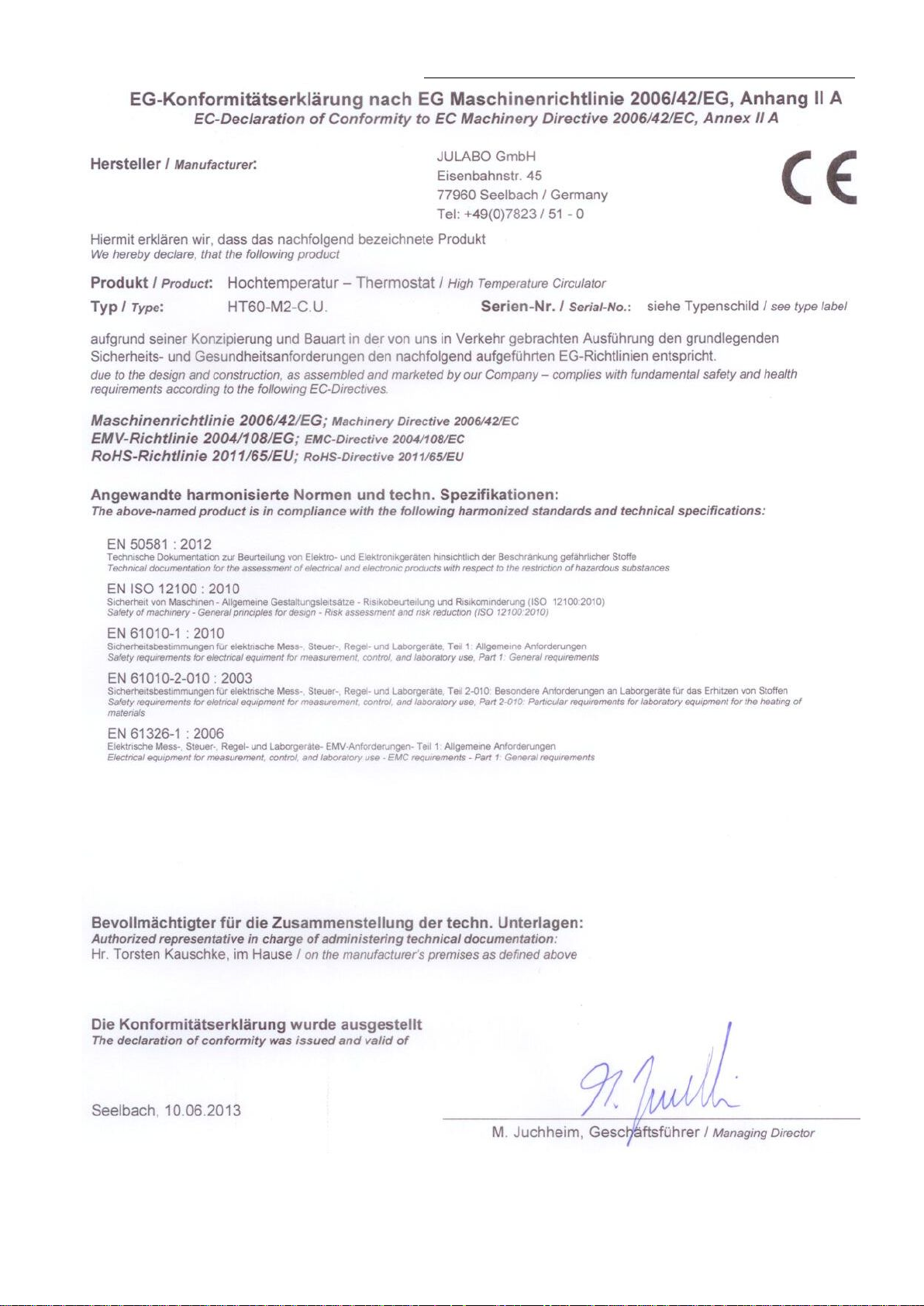
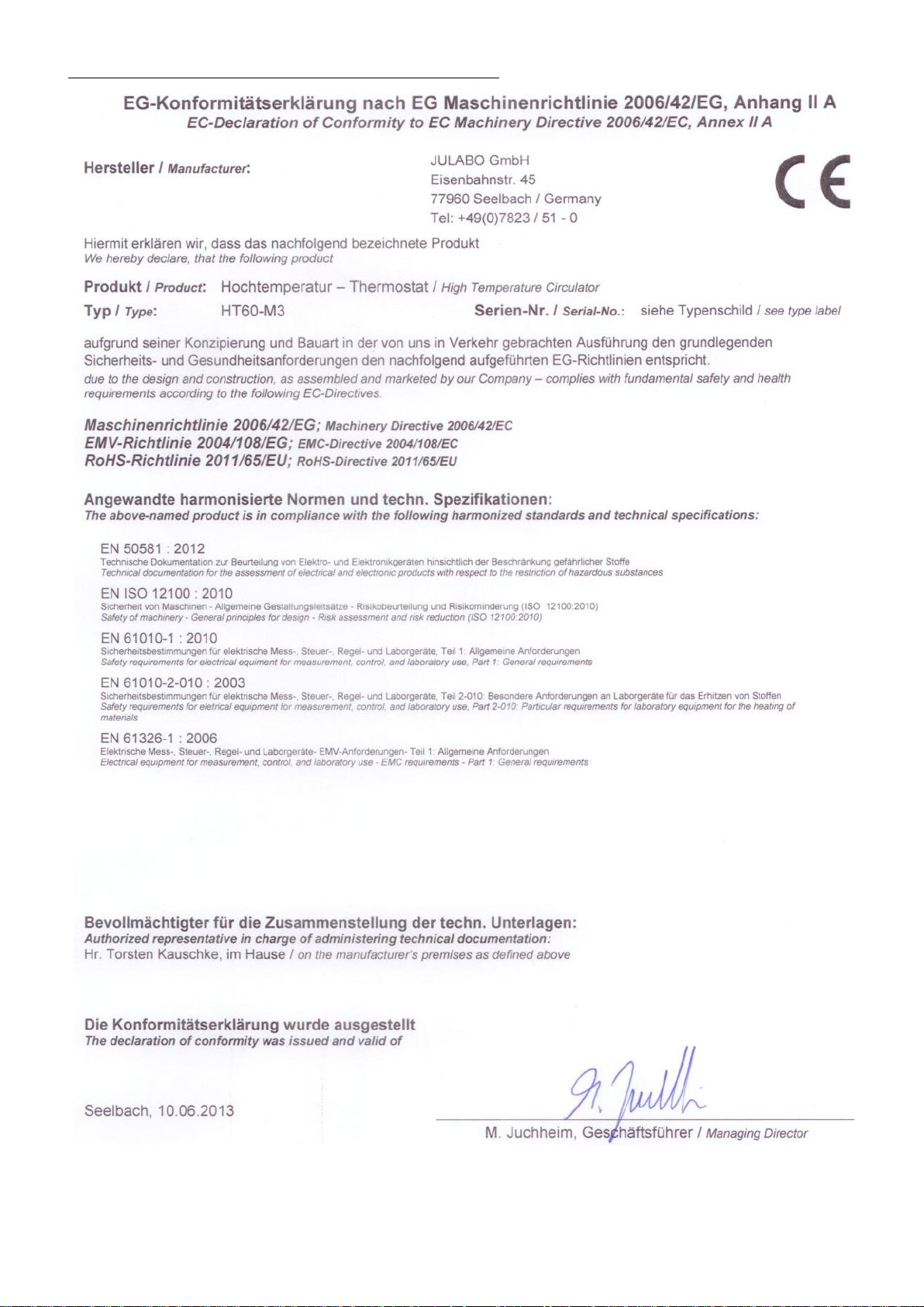
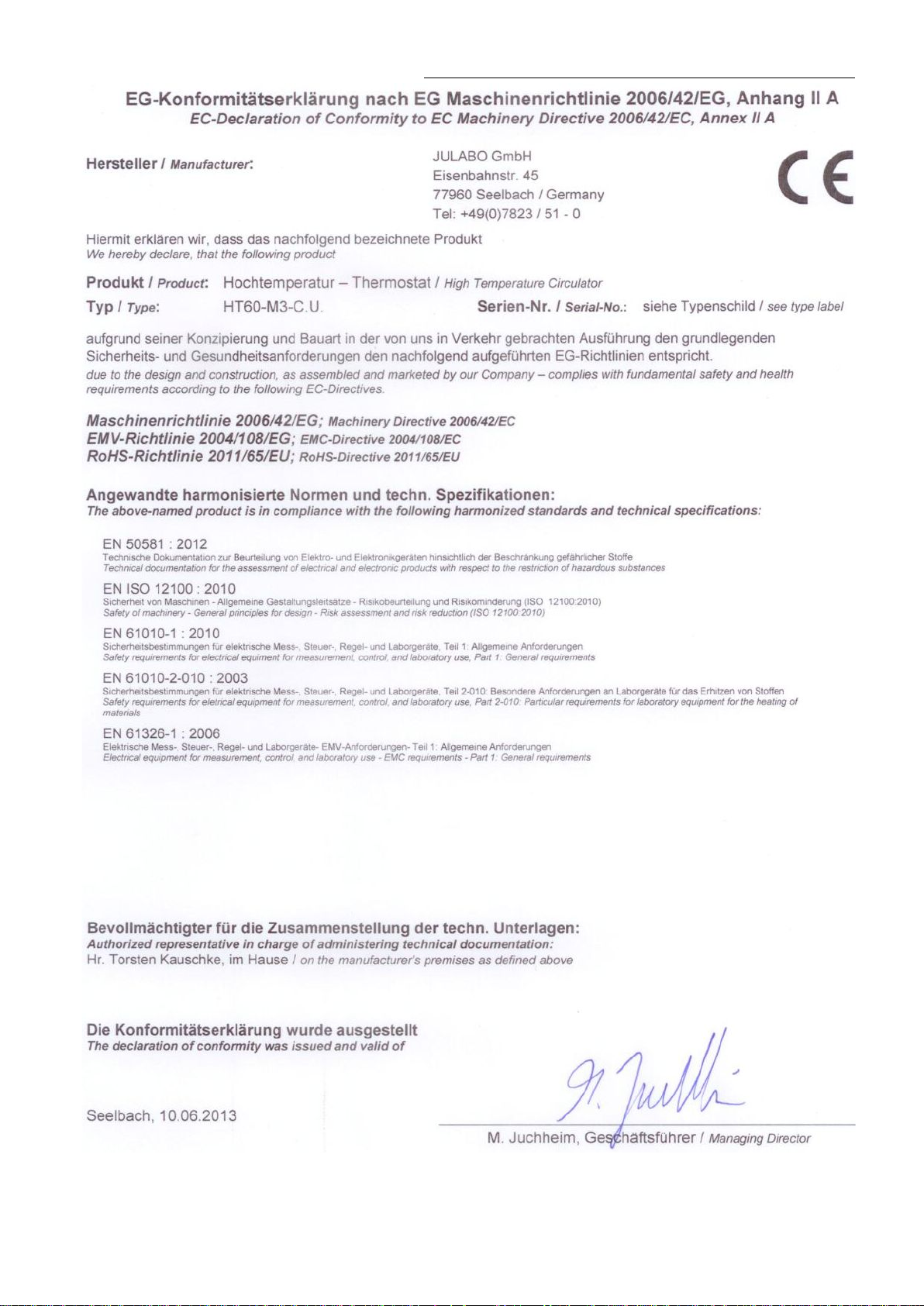
2.2. EC Conformity
8
Page 9
HT60-M2 / HT60-M3
9
Page 10
Operator responsibi lity – Safety instructions
10
Page 11
HT60-M2 / HT60-M3
11
Page 12

Operator responsibi lity – Safety instructions
2.3. Warranty conditions
JULABO GmbH warrants its products agai nst defects in material or in workmanship, when used under
appropriate conditions and in accordance wit h appr opr iate operating instruc tions
for a period of ONE YEAR.
Extension of the warranty period – free of charge
With the ‘1PLUS warranty’ t he user rec eives a free of charge extensi on to the warranty of up to 24 months,
limited to a maximum of 10 000 worki ng hour s.
To apply for this ext ended warrant y the user must register the unit on t he J ULABO web site
indicati ng the seri al no. The extended warranty will apply from the dat e of JULA BO GmbH’s original invoice.
JULABO GmbH reserves the right to decide the validity of any warranty cl aim . In case of f aults arising either
due to faulty materials or workmanship, parts will be r epair ed or r eplac ed free of charge, or a new replacement
unit will be suppli ed.
Any other compensation claims are excluded from this guarantee.
www.julabo.de,
12
Page 13

2.4. Technical specifications
HT60-M2 HT60-M2 & C.U.
Working temperature range
°C
70 ... 400 40 … 400
Temperature stability external
°C
±0,01 ... ±0.1
Display accurac y
%
±0.5 ±1Digit
Temperature selec tion
digital
via keypad
indicati on on LCD DIALOG -DISPLAY (°C/°F)
remote control via PC
indication on monitor
Temperature indication
Multi-Display (LED)
DIALOG-Display (LCD)
Resolution
°C
0.01
Absolute Temperature Calibration
(ATC 1)
°C
±9.99
(ATC 2)
°C
±9.99
Temperature control
ICC - Intelligent Cascade Control,
self-optimizing
Cascade, parameter c an be c alled-in and modified
Heater wattage (at 3x400 V)
kW
7.0
C.U.-cooling unit:
at 2 l/min flow of cooling water
Pressure pump:
Max. pressure max. at 0 liters
bar
0.8 … 1.2
Flow rate max. at 0 bar
l/min
14 … 18
Electrical connections:
See page 15
Filling volume
litre
2
Overall dimensi ons (W x Dx H) M2 / M3
cm
25x25x18 25x25x18
Weight
kg
29 37
Ambient temperature
°C
5 ... 40
400V/3PNPE/50Hz
Current draw
A
10.5 (at 400 V) 10,5 (400V) & 1 (230V)
HT60-M2 / HT60-M3
Temperature <IntAct>
Cooling capacity
Overall dimensi ons (W x Dx H) HT60 cm 23x23x58 43x23x58
Mains power connection
All measurements have been carried out at:
rated voltage and frequency ambient temperatur e: 20 °C
Technical changes without prior notification reserved.
°C
kW
V / Hz 365-440V/3PNPE/50Hz & 207-253V/50-60Hz
----- 350 250 150 75
----- 12 8 4 1
13
Page 14

Operator responsibility – Safety instructions
HT60-M3 HT60-M3 & C.U.
Working temperature range
°C
70 ... 400 40 … 400
Temperature stability external
°C
±0,01 ... ±0.1
Display accurac y
%
±0.5 ±1Digit
Temperature selec tion
digital
via keypad
indicati on on LCD DIALOG -DISPLAY (°C/°F)
remote control via PC
indication on monitor
Temperature indication
Multi-Display (LED)
DIALOG-Display (LCD)
Resolution
°C
0.01
Absolute Temperature Calibration
(ATC 1)
°C
±9.99
(ATC 2)
°C
±9.99
Temperature control
ICC - Intelligent Cascade Control,
self-optimizing
Cascade, parameter c an be c alled-in and modified
Heater wattage (at 3x400 V )
kW
6.0
C.U.-cooling unit:
at 2 l/min flow of cooling water
Pressure pump:
Max. pressure max. at 0 liters
bar
0.8 … 1.2
Flow rate max. at 0 bar
l/min
14 … 18
Electrical connections:
See page 15
Filling volume
litre
2
Overall dimensi ons (W x Dx H) M2 / M3
cm
25x25x18 25x25x18
Weight
kg
29 37
Ambient temperature
°C
5 ... 40
208/3PPE/60Hz
Current draw
A
18 (at 208 V) 18 (208V) & 1 (230V)
Temperature <IntAct>
Cooling capacity
°C
kW
----- 350 250 150 75
----- 12 8 4 1
Overall dimensi ons (W x Dx H) HT60 cm 23x23x58 43x23x58
Mains power connection
V / Hz 180-228V/3PPE/60Hz &207-253V/50-60Hz
All measurements have been carried out at:
rated voltage and frequency ambient temperature: 20 °C
Technical changes without prior notification reserved.
14
Page 15

HT60-M2 / HT60-M3
Electrical connections:
Computer interf ac e RS232 or RS485 or Profi
Programmer input 0 - 10 V / 0 - 20 mA
Temperatur rec or der outputs Channel 1 / 2 0 - 10 V /
Channel 3 0 - 20 mA / 4 - 20 mA
Stand-by input
External alarm devic e Switching capaci ty max. 30 W / 40 VA
Switching voltage max. 125 V∼/−
Switching cur r ent max. 1 A
External measurem ent and controlsensor Pt100, 4-lead technique
Safety installations according to IEC 61010-2-010:
Excess temperatur e pr otection adjustable fr om 0 °C to 420 °C
Low liquid level protection float switch
Liquid level indication optical 8-graded
Rèpartition par cl asse selon DIN 12876-1 Classe III FL
Supplementary safety installations
High temperat ur e warning func tion optical + audible (in intervals)
Low temperature warning function optical + audible (in intervals)
Supervision of the worki ng sensor plausibility c ontrol
Reciprocal sensor monitoring between
working and safety sensors difference >100 K
Alarm indicati on optical + audi ble ( permanent)
Environmental conditions according to IEC 61 010-1:
• Use only indoor.
• Altitude up t o 2000 m - normal zero.
• Ambient tem per ature: see Technical specific ations
• Air humidity:
Max. rel. humidity 80 % for temper atures up to +31 °C,
linear decrease down to 50 % relative humidity at a temperature of +40 °C
• Max. mains fluctuations of ±10 % are permissible.
• Overvoltage category II
• Pollution degr ee 2
Caution:
The unit is not for use in expl osive environment
Protection class according to IEC 60 529: IP31
The unit corresponds to Class I
Standards for interference resistance accor ding to EN 61326-1
This unit is an ISM device classified in Group 1 (using high frequency for internal purposes) Class A (industr ial
and commercial range).
15
Page 16
Operator responsibi lity – Safety instructions
• Avoid putrid water.
pH
7.5 to 9.0
Sulfate [SO4 2- ]
< 100 ppm
Hydrocarbonate [HCO 3-]/sulfate [SO4 2-]
> 1 ppm
Hardness [Ca 2+, Mg 2+]/[HCO 3-]
> 0 .5 °dH
Alkalinity
60 ppm < [HCO 3-] < 300 ppm
Conductivity
< 500 μS/cm
Chloride (Cl -)
< 50 ppm
Phosphate (PO4 3-)
< 2 ppm
Ammonia (NH3)
< 0.5 ppm
Free chlorine
< 0.5 ppm
Trivalent iron ions (Fe 3+)
Carbon dioxide ( CO2)
< 10 ppm
Hydrogen sulfide ( H2S )
< 50 ppm
Content of oxygen
Algae growth
impermissible
Suspended solids
impermissible
2.5. Cooling water connection
Cooling water pressure (IN / OUT ) max. 4.5 bar
Differenc e pressure (I N - O U T ) 2.0 to 4.5 bar
Rate of flow typical 2 l/min
Cooling water tem per ature <20 °C
Notice:
Danger of corrosion of heat exchanger due to unsuitable quality of cooling water.
• Due to its high content of lime, hard water i s not suitable for cooling and causes scale in
the heat exchanger.
• Ferrous water or water containing ferrous particles will cause form ation of rust even in
heat exchangers made of stainless steel.
• Chlorinated water will cause pit ting corrosion in heat exchangers m ade of stainless steel.
• Due to their corrosive characteri stics, distilled water and dei onized water are unsuitable
and will cause corrosion of the bath.
• Due to its corrosive characteri stics, sea water is not suitable.
• Due to its microbiological ( bacter ial) components, which settle in the heat exchanger,
untreated and unpurified river water and water from c ooling towers is unsuitable.
• Avoid particulate matt er in cooling water.
Recommended quality of cooling water:
Manganese ions (Mn 2+)
< 0.5 ppm
< 0.05 ppm
< 0.1 ppm
16
Page 17
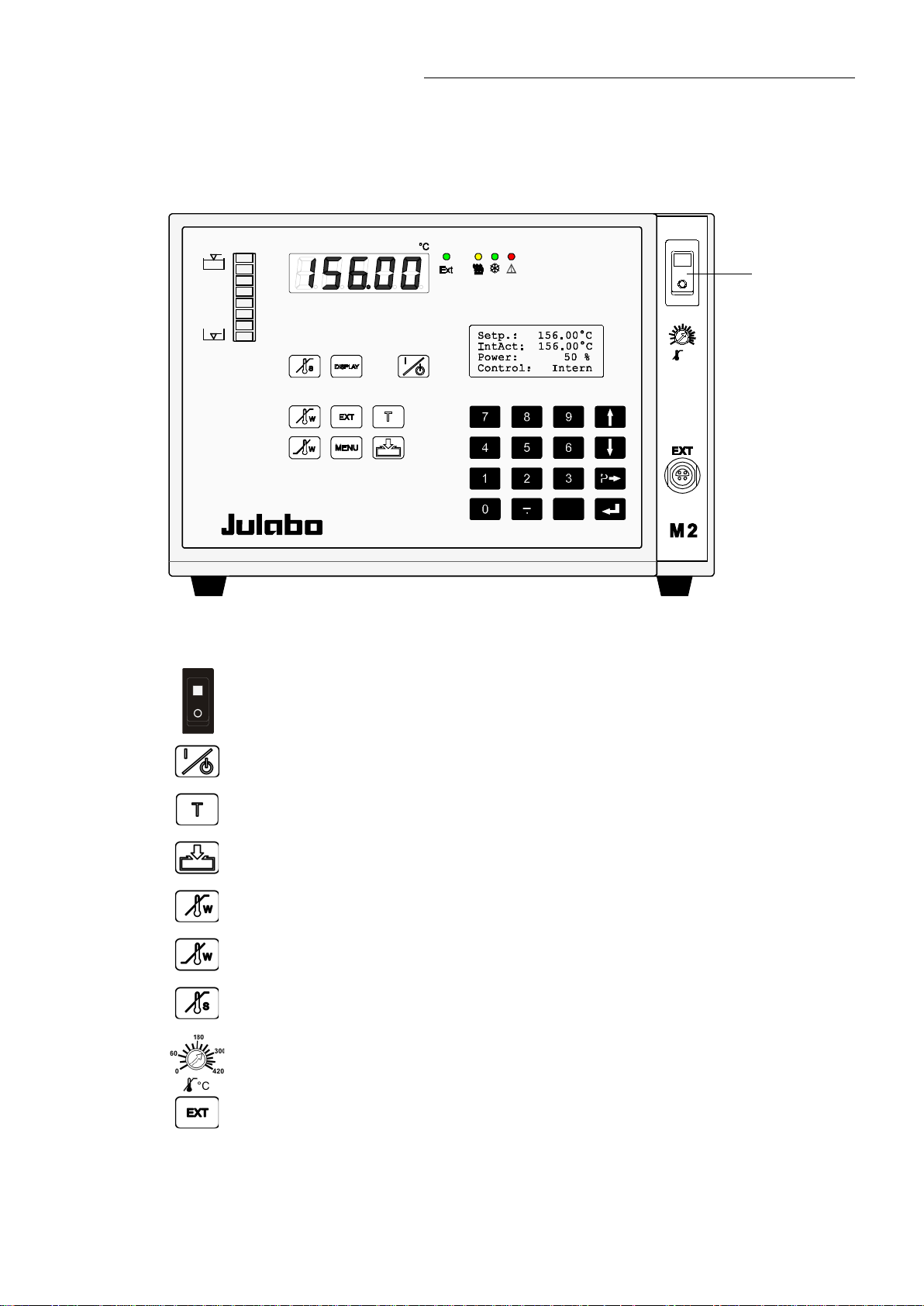
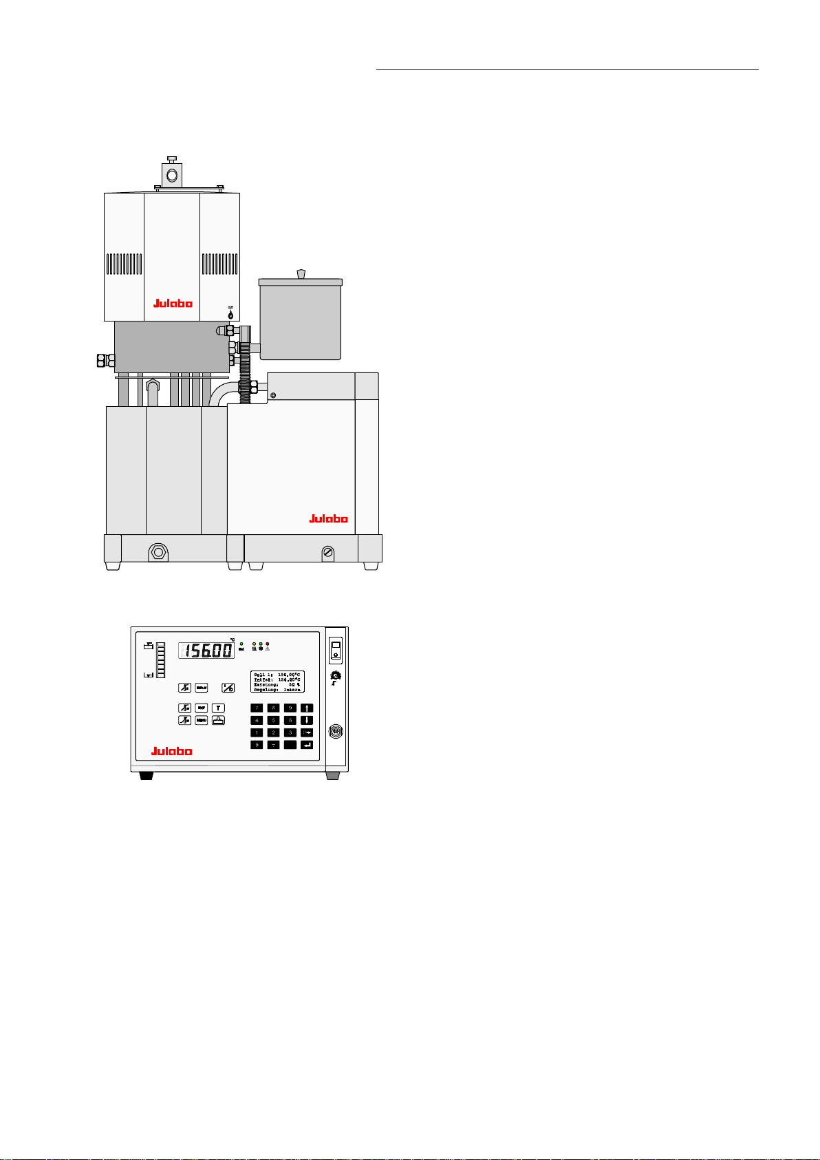
3. Operating controls and functional elements
1
-
ESC
P
0
60
180
300
420
°C
M2 or M3 – control electronic
HT60-M2 / HT60-M3
1
2
3
4
5
6
7
8
Mains power switch, illuminated
Start / stop key
Working temperature T
Key for automatic filling and aeration
High temperat ur e warning limit
Low temperature warning lim it
Safety temperature
Adjustable exc ess temperature protection ( safety temperature)
9
Control type: internal/external control
17
Page 18
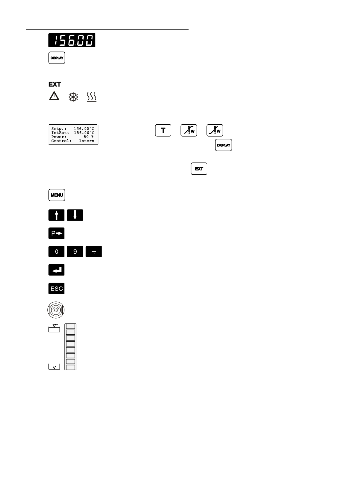
Operating controls and functional elements
10
11
12
13
/ /
MULTI-DISPLAY (LED) temperature indication
Display of internal/external actual value
Indicator li ghts:
Temperature indication - external actual value
Alarm / Cooling / Heating
DIALOG-DISPLAY (LCD) for indication of:
Line 1: Setpoint or or
Line 2: Internal or exter nal actual value
Line 3: Heating power in %
Line 4: Control type: internal / external control
MENU key - for selecting the menu functions
14
15
16
17
18
19
EXT
20
Cursor keys - Select menu items
P-key Selecting paramet er s
Numeral keypad: numerals 0 to 9; minus / decimal point
Enter key 1) St or e v alue / param eter
2) Next lower menu level
Escape key 1) Cancel entries
2) Return to a higher menu level
Socket for exter nal m easurement and control sensor Pt100
8-grade liquid level indication
18
Page 19
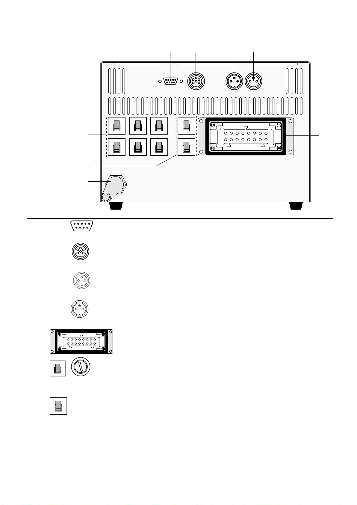
Rear view
30 31 32 33
1
8
916
4
A
M
P
HT60-M2 / HT60-M3
REG+E-PRO G STAND-BY ALARMSERIAL
30
31
32
36
37
38
SERIAL
REG+E-PROG
STAND-BY
16
A
M
P
16
A
M
P
16
A
M
P
16
A
M
P
16
A
M
P
16
A
M
P
4
A
M
P
4
A
M
P
8
HT60
916
1
MADE IN GERMANY
35
Interface RS232/RS485
Programmer input and temperature recorder out put
Stand-by input (f or ext er nal em er genc y switc h-off)
33
Alarm output (for exter nal alarm signal)
ALARM
35
Control exit Connector for contr ol cabl e of cir c ulator HT60
36
37
38 Mains power cable with pl ug
16
A
M
P
M2 – Mains circuit breaker s (resettable): 3x Mains fuses 16 A,
or
M2 – 3x fuse holder with fein-wire fuses T16A, 5x20 mm
M3 – Mains circuit breaker s (resettable): 6x Mains fuses 16 A,
Mains circuit break er s (resettable): Fuses 4 A, for C.U. -cool ing unit
19
Page 20
Operating controls and functional elements
HT60
CU
40
41
42
43
44
53
54
41
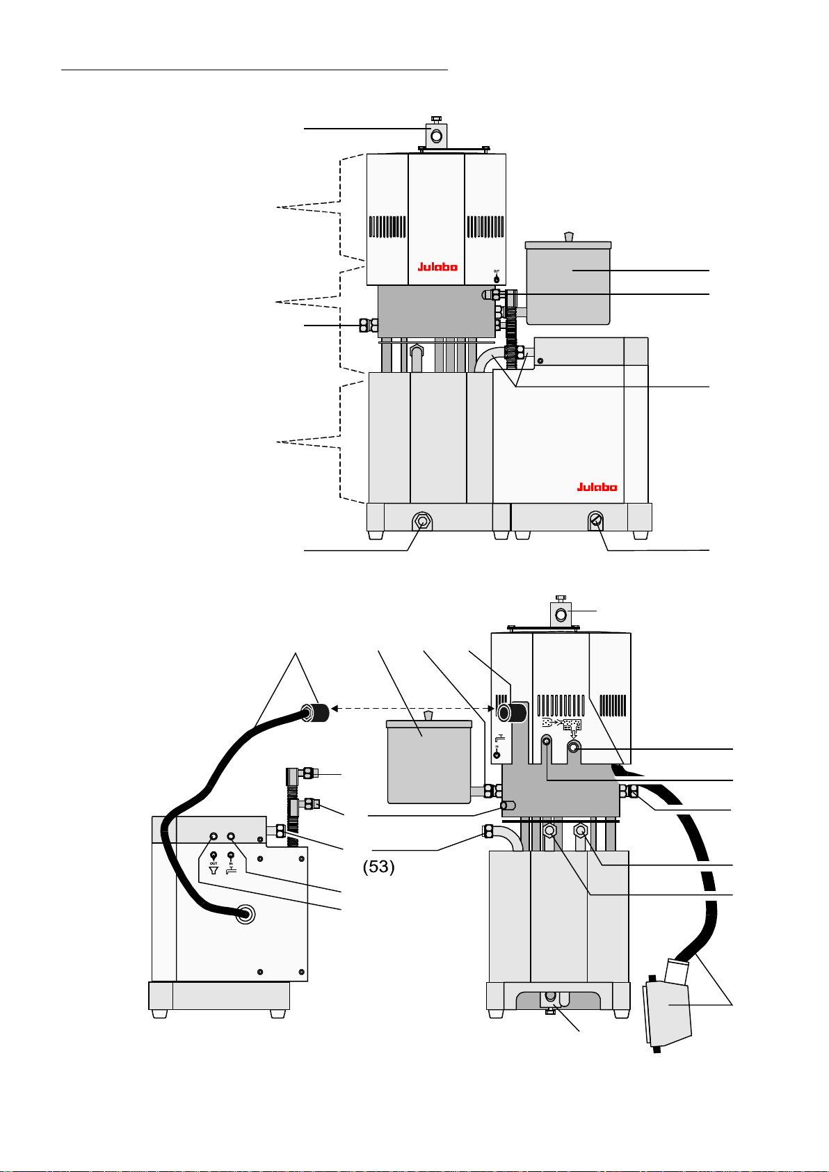
HT60 High Temperature Circulator with C.U.-cooling unit (option)
Front view:
Cold zone
Cooling zone
Heating zone
Rear view:
56
43 43a
44
45
52
46
47
40
56a
48
49
50
51
40
Presentation: Cooling unit divided from HT60
20
55
Page 21
40 Stand rod attac hm ent wit h mouting screw; ∅12; M8
41 Connector for liquid level indicator or
second expansion vessel; M16x 1 / ∠37°
42 Drain plug for bat h liquid; M16x1
43/43a Expansion vessel / Connector for expansion vessel; M16x1
(When filling it serves as funnel)
44/45
46/47
48
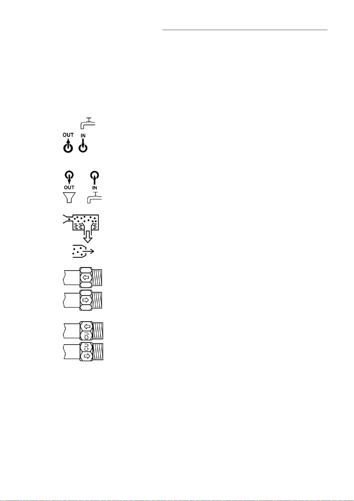
Cooling water connectors at the HT60, M12 / ∠37°
OUT – outlet (44), IN – inlet (45)
• Connection for cooling water or
• Connection for clocked cooling water with magnetic valv e or
• Connection for clocked cooling water out of t he CU-unit
Cooling water connectors at the C.U.-cooling unit; ∅10
IN –inlet, OUT – outlet
Overflow connector ∅15,5 / G ¼ ″ Internal thread
HT60-M2 / HT60-M3
49
50
51
52
53
54 Drain plug for cooling water; M10x1
55 Control cable wit h 16-c hannel plug for
56
56a
56a
Control cable wit h 6-c hannel plug for connection of the C.U.-cooling unit
Inert gas connector ∅10; M 8x 1 Internal thread
Pump connector f or ext er nal temper atur application
Return; 16x1
Pump connector f or ext er nal temper atur application
Feed ; 16x1
Pump connector f or C.U.-cooling unit - Return; M16x1
(Cooling circuit )
Pump connector f or C.U.-cooling unit - Feed; M16x1
(Cooling cir c uit )
connection of the M 2 or M3 control elec tronics
Control exit for C.U.-cooling unit
or
Control exit for magnet ic valve (for clocked cooling water)
21
Page 22

Safety notes for the user
surroundings can be dam aged.
Indicates usage ti ps and other useful information.
valid safety instructions for working places must be followed.
short moment for example).
4. Safety notes for the user
4.1. Explanation of safety notes
In addition to the safety warnings listed above, warnings are posted t hr oughout the manual.
These warnings are designat ed by an ex cl am ation mark inside an equilateral triangle.
“Warning of a dangerous situation (Attenti on! Please follow the documentation).”
The danger is classifi ed usi ng a si gnal word.
Read and follow these im por tant instructions.
Warning:
Describes a possibl y highly danger ous sit uation. If these instruc tions are not followed, serious
injury and danger t o life could result.
Caution:
Describes a possibl y danger ous sit uation. If this is not avoided, slight or minor injuri es could
result. A warning of possibl e pr oper ty damage may also be contai ned in the t ex t.
Notice:
Describes a possibl y harmf ul si tuation. If this is not avoided, the pr oduc t or anything in its
4.2. Explanation of other notes
Note!
Draws attention to something special.
Important!
4.3. Safety instructions
Follow the safet y recommendations to prevent damage to persons or propert y . Further, the
• Only connect the unit to a power socket with earthing contact (PE – protective earth)!
• The power supply plug serves as safe disconnecti ng devi c e from the line and must be
always freely accessible.
• Place the i nstr um ent on an even surface on a pad made of non-flammable material.
• Do not stay in the area below the unit.
• Make sure you read and understand al l instructions and safety precauti ons li sted in this
manual before install ing or operating your unit.
• Set the safet y tem per ature.
• Never operate the unit without bath fluid in the bath.
• Pay attention to the thermal expansion of bath oil during heating to avoid overflowing of
the fluid.
• Prevent water f r om penetr ating into the hot bath oil.
• Do not drain the bat h fluid while it is hot!
Check the temperature of the bath fluid prior to drai ning (by switching the unit on for a
22
Page 23
HT60-M2 / HT60-M3
method of decontamination.
• Employ suitable connecting tubing.
• Avoid sharp bends in t he tubing, and maintain a suffi ci ent distance from surrounding walls.
• Make sure that the tubing is securely attached.
• Regularly check the tubing for material defects (e.g. for cracks).
• Never operate damaged or leaking equipm ent.
• Always turn off the unit and disconnect the mains cable f r om the power source before
performing any servi c e or mai ntenance pr oc edur es, or before moving the unit.
• Always turn off the unit and disconnect the mains cable f r om the power source before
cleaning the unit.
• Transport the unit with care.
• Sudden jolts or drops may cause damages in the interior of the unit.
• Observe all warning labels.
• Never rem ov e warning l abels.
• Never operate equipment with damaged mai ns power cables.
• Repairs are to be car ri ed out only by qualified servi c e personnel.
Some parts of the bath cover and the pump c onnec tions may become extremely warm during
continuous operation. Therefore, ex er ci se parti c ular caution when touching these part s.
Caution:
The temperatur e contr olling i.e. of fluids in a react or constit utes normal temperature system
practice.
We do not know which substances are contained within these vessels.
Many substances are:
• inflamm able, easily ignited or explosive
• hazardous to health
• environmentally unsafe
i.e.: dangerous
The user alone is responsible for the handling of these substances!
The following questions shall help to recognize possible dangers and to r educ e the risks to a
minimum.
• Are all tubes and electrical cables connected and installed?
Note:
sharp edges, hot surfac es i n oper ation, moving machine parts, etc.
• Do dangerous steams or gases arise when heating?
Is an exhaust needed when working?
• What to do when a dangerous substance was spilled on or in the unit?
Before starting to work, obtain informati on c onc er ning the substanc e and determine the
Notice:
When you have finished the appl ication, it is recommended to keep on ci r c ulating the liquid in
the bath or the external system for some time. Simultaneously set the working temperatur e to
+20 °C to allow the temperatur e in the system to decrease slowly.
Thus fractional ov er -heating of the bath liquid is prevented.
23
Page 24

Safety notes for the user
Notice:
Check the safety installations at least twice a year!
• Excess temperature protecti on according to IEC 61010-2-010
With a screw driver turn back the adjustable excess temper ature protection until the shutdown point (act ual temper ature).
• Low level prot ec tion
To check the function of the float of this unit it cannot be operated manually.
The 5-graded level display shoul d therefore be observed whenv er r efilling.
If the bath liquid thickens or cracks, the instrument shoul d be cl eaned and c hec k ed by
qualified per sonnel .
24
Page 25
5. Preparations
HT60
CU
-
ESC
P
M2
0
60
180
300
420
EXT
°C
5.1. Setup
HT60-M2 / HT60-M3
High temperature circulator HT60 as well as
High temperature circulator HT60 with CU cooling
unit:
as a desktop unit
• Place the circulator on an even surf ac e on a pad
made of non-flammable material.
as a stand-mounted unit
• Place the unit in an vertical position.
• A wall distance of at least 15 cm m ust be
maintained for v entilation, allowing internal heat to
be conducted away from the unit.
JULABO Order-No.
9790100 C.U. cooling unit
M2 or M3 remote control electronics:
• The unit should be set up at a dry location.
• Place the unit in an upri ght position and do not
obstruct the ventilation Ambient temperatures
above 40 °C result in a fail ur e of the uni t.
• Do not set up the unit in the imm ediate vicinity of
heat sources and do not expose to sun light.
25
Page 26

Preparations
(see 8.6. Limits).
44
45
56
52
60
62
61
64
63
K11
K14
56a
5.2. Installation
Caution:
Installation of the C.U.-unit / Installation of the magnetic valve
• Always turn off the unit and disconnect the mains cable (38) from the power source
• The control c able with plug (56) of the C.U.-cooling unit or the magnetic valve always
Control of the C.U.-cooling unit or the magnetic valve.
before installing the unit.
have to be connected or disconnected in absence of current.
• With the C.U.-cooling unit or the magnetic valve the menupoint
–CoolingMax- has to be adjusted to a value of > 0 (Recommendation: 100%). So the
automatic al contr ol of the cooling can become active
Installation of the C.U.-unit
JULABO Order-No. 9790100 C.U. cooling unit
• Use the leader pi ns (62) to fix
the assembly sheet (60) into the
base (61) of the circulator and
fasten with hexagon screws
(63).
• Push the C.U.-cooling unit to the
circulator and screw it ti ghtly at
the points (64).
• Connect the cooling circulation
for the oil (52, 53) (open end
wrench SW19). When doing t his
hold the tube at positi on K 11
with an open end wrench SW21.
26
• Connect the cooling water (44, 45) (open end wrench SW15)
When doing this hold the t ube at position (K14) with an open end
wrench (SW14)
• Fix the control c able (56) at the control exit (56a) and screw it tightly.
Cooling capacity at 2 l/min flow of cooling water.
Temperature <IntAct> [°C] 350 250 150 75
Cooling capacity [kW] 12 8 4 1
Page 27

HT60-M2 / HT60-M3
5051
43
45
41
56
Installation of the magnetic valve
JULABO Order-No. 8 980 704 3 Magnetic valve
• Fix the expansi on tank (43) to the connection (41) ( open
end wrench SW19)
• Screw the magnetic valve to the entry for cooling water
(45). Respect the fl ow dir ec tion (arrow)
Connect the cooli ng water to the magnetic valve and to the
outflow of cooling water (44) by means of tubes 8 mm ID.
• Fix the control c able (56) at the control exit (56a) and srew
tightly.
Notice:
When using pressure sensitive glass vessels, it is absolutely necessary to work with
an adapter to reduce the pump pressure.
Caution:
Securely attach all tubing to prev ent slipping.
Adapter to reduce the pump pressure
JULABO Order-No. 8 970 802
With this adapter t he pum p pressure at the pump connection
(51) can be reduced from 1,2 bar to
0,8 bar
Assembly
• Fix the adapt er t o r educ e the pump pr essure to t he pump
–0,1
.
connections (50, 51) ( open end wrench SW19).
27
Page 28

Preparations
If a bath fluid with a fire point of ≤65 °C is used, only supervised operati on is possible.
No liability for use of other bath fluids!
Setp.: xxx.xx°C
hot cooling zone
5.3. Bath fluids
Caution:
Carefully read the safety data sheet of the bath liqui d used, particularly with regar d to the fire
point!
Recommended bath fluids
Co
ntact: see page 6.
Caution:
Fire or other dangers when using bath fluids that are not recommended:
See website for list of recommended bath fluids.
Please contact J ULA BO before usi ng other than recommended bath liquids.
JULABO assumes no liabili ty for damage caused by the selecti on of an unsuitable bath fluid.
Unsuitable bath fluids are fluids which, e.g.,
• are highly viscous
(much higher than 30 mm2 x s-1 at the respective working t em per ature)
• have a low viscosit y and hav e creep char ac teristics
• have corr osive characteristic s or
• tend to crac k.
ATTENTION: The maximum permissible viscosity is 30 mm
Caution:
The use of water in purified or unpur ified form is not allowed.
Examples: Tap water, distilled water, water-glycol mixture, CaCl2-brine
2
x s
-1
.
Tempering liquid
The circulator c an only be oper ated in closed tempering cir c uits. The contact of the
tempering liquid with atmospherical oxygen only takes place in the not-flowed cooling
zone. A safety equipment with definitely adjusted temperature value (170° C ±5 °C)
works independantly from the control circuit and supervises the temperature in the
cooling zone. From 160 °C on the warning >hot cooling zone< is shown in li ne 4 of
the DIALOG-DISPLAY (LCD).
Important notice
IntAct: xx.xx°C
Power xx %
Control: intern
If the temperature of the liquid r eac hes the safety temperature (170 ° C) , a com plete
shutdown of the controlled heating device is effec ted. So it becomes possible to use
tempering liquids with a flashpoint from 190° C on.
From a working temperature of 200°C on always work with counter-cooling.
28
Page 29

5.4. Tubing
8 930 214
3.0 m
8 930 223
3.0 m
Regularly check the tubing for material defects (e.g. for cracks)..
Recommended tubing:
Metal tubing, t ri ple insul ated, M16x1, Temperature range -100 °C ... + 350 ° C
Order No. Length
HT60-M2 / HT60-M3
8 930 209
8 930 210
8 930 211
Metal tubing, insulated, M16x1, Temperature range -50 °C ... +200 °C
Order No. Length
8 930 220
8 930 221
8 930 222
Pressure max. 6.0 bar at +20 °C
4.6 bar at +200 °C
3.8 bar at +350 °C
Warning:
Tubes:
At high working temper atures the tubing used for temperatur e application and cooling water
supply represents a danger sourc e.
A failure of the counter-cooling, e.g. t hr ough br ok en tubes can cause higher temperat ur es i n
the cooling zone. Due to a damaged temper ing tube hot tempering liquid can be pumped out
within a short tim e.
These are possible results:
• Danger of fire
• Danger of ex plosi on
• Burning of peopl e’s skin
• Diffi c ulties in breathing due to hot atmosphere
JULABO supplies the met al tubes with assem bly instructions
(No. 1.950.0013). There all the instruction f or assembly are indicated. They absolut ely have
to be respected.
Safety recommendat ions
• Employ suitable connecting tubing.
• Make sure that t he tubes are securel y attached.
• Avoid sharp bends in t he tubing, and maintain a suffici ent distance from surrounding
walls.
•
0.5 m
1.0 m
1.5 m
0.5 m
1.0 m
1.5 m
29
Page 30

Preparations
5.5. Power connection
Caution:
1. Connect control cable (55) with control exit (35) of the control electronics M2 / M3 and
latch the saftey loop.
Lengthening piec e for control cable, 5 m - JULABO Order-No. 8 980 125
2. If available screw the C. U.-cooling unit tightly to the control exit (56a) of the HT60 by
means of the control cable ( 56) .
3. Connect the mains plug (38) of t he c ontrol electronics to a power socket wit h ear thing
contact (PE – protective earth)!
• The available supply voltage and the power frequenc y hav e to be com par ed with the
specifications on the type plate.
Voltage differences of ± 10 % are allowed.
• The power supply plug serves as a safe disconnecting devi c e from the line and must
always be easily acc essible.
• Never operate the unit with a damaged mains power cable.
• Regularl y check the mains power cables for damage.
• We disclaim all li ability for damage caused by incor r ec t line voltages!
5.6. Filling / draining
Caution:
• The lines of t he exter nal system should be well cleaned in or der to av oid soil par ticles
30
(sand, metal chips) f r om bei ng ri nsed i nto the circulator. Danger for magnetic valves and
the pump.
• The tempering liquid must not contai n water!
Preparing the tempering liquid:
Heat the oil up to 110C in an open bath to boil off any water.Tempering time
approximately 1 hour.
In case of high temperatures water parts in the tempering liquid can cause damages
in the HT circulator!
Recommendation :
After each refilling a degasifying of the tempering liquid should be made.
Page 31

HT60-M2 / HT60-M3
43
48
49
50
51
55
52
43a
41
Store and dispose the used bath fluid according to the laws for environment al pr otection.
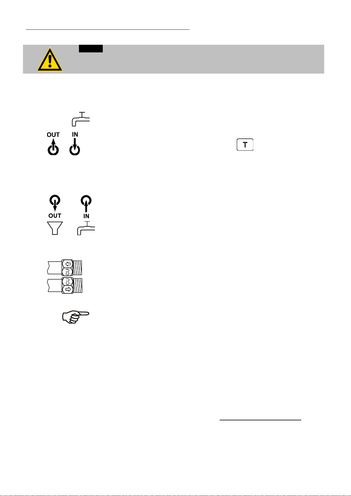
Filling
1. Attach a tube at the overflow nozzle (48) and lead it into a
suitable vessel.
2. Remove the screw plugs from the pump c onnec tion (50,
51) and connect it to the exter nal system by means of
metal tubes (open end wrench SW 19)
3. Remove the screw plug from the connec tion (43a) and
srew on the expansion tank (43)
4. Always close tightl y the connec tions which have not been
used (e.g. 41 or 52, 53) wit h screw plugs, the drai n plug
(42) is also important.
5. Connect the mains supply (see above) and switch on the
mains switch (1).
6. Fill the unit by pouring the fluid into the expansion tank ,
which is connected to the cooling zone.
7. Operate key
Internally a valve opens the passage to the heating zone.
With a reduced no. of rotati ons the pum p m otor pumps the
tempering liquid into the externally connected consumer.
8. Slowly refill temper ing liquid until two or three segm ents of the level indication
light up. The necessary quantity of li quid then is in the tempering system.
9. If the minimum level liquid remains under, a low level alarm E01 can be caused.
By a short switching-off and switc hing-on again at the mains switc h ( 1) the alarm
status is cancell ed.
Afterwards again refill the tempering liquid and operate the key until two or
three segments of t he lev el indic ation lighten.
10. Operate key in order to finish the filling process.
Notice:
• Do not drain the bat h fluid while it is hot or cold !
Check the temperature of the bath fluid prior to drai ning (by switching the unit on for a
short moment, for example).
•
Draining
1. Cool the fluid below 40C and then tur n off the mains switch.
2. Place the circulat or to t he table edge and put under a suitable vessel to uptak e the
used tempering liquid.
3. For emptying unscrew the drain nut (42) on the front of the HT30 and have t he
tempering liquid run into a suitable vessel.
31
Page 32
Preparations
Setp. : 37.00°C
Setp.: 20.00°C
IntAct: 50.40°C
Power 0 %
Control: intern
Enter temperatur
Setp.: 250.00°C
IntAct: 80.00°C
Power 10 %
Control: intern
degasing aktiv
Setp.: 250.00°C
IntAct: 250.00°C
Power 50 %
Control: intern
degased->Enter
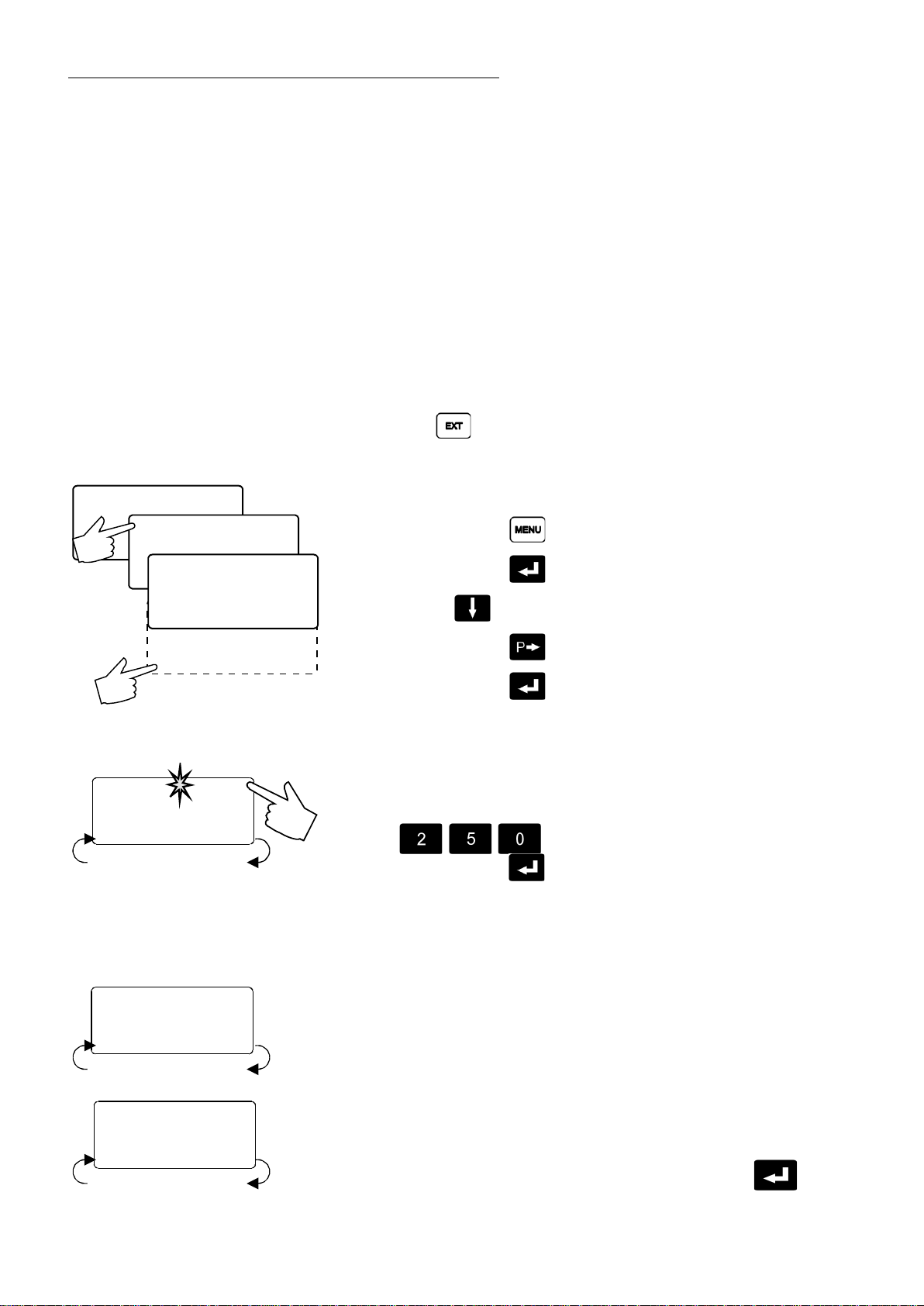
5.7. Degasifying
ExtAct: ---.--°C
Power: 0 %
Control: intern
>Configuration
Control param.
Configuration
Identif. xxxxxx
Setpoint xxxxx
Autostart xxx
Standby xxxx
Language engl.
>De-Gas on
During the filling pr oc ess the pump fluidizes air bubbl es i nto the
tempering liqui d. I n the aut om atic degasifying mode those and other light
solvent substances are sl owly dr ained from the oil via the breather tube.
Notice:
In the automatic degasifying mode the breather tube between heati ng
and cooling zone is opened agai n and again. Hot gases and selfextending tem peri ng liquid therefore get int o the cooling zone. Therefore
in case of a target temperat ur e whic h is hi gher than 150°C a countercooling in the cooling zone should be possible.
(See 5.8. Countercooling)
• Switch on the control electronics by the mains switch (1)
• With key switch to „internal control“.
• Operate the foll owing k ey s one aft er the ot her as described i n or der
to get into the degasifyi ng m ode or to leave it. On the DIALOGDISPLAY (LCD) the differ ent actions can be followed-up.
1. MENUE-key 1x
2. Enter-key 1x
3. Cursor-key 5x
4. P-key 1x
5. Enter-key 1x
6. Now in line 4 of the DIALOG-DISPLAY there is the demand to set a
temperature value ( „ E nter temperature“)
Example: 250°C
For this operat e the following keys
With the Enter-key the value is stored
and
at the same time the degasifyi ng m ode is start ed.
(Also see „Temperatur e setting“ page 20)
7. The temperatur e is autom atically increased step by step by 2°C.
Each time there is a standsti ll of approximately one minute. In line 4
of the DIALOG-DISPLAY ( LCD) the degasifying mode is indicated by
blinking.
8. When the target tem per ature is reached, the degasifying mode is
finshed.
A signal tone sounds in i nterv als and in line 4 of the DIALOG-
32
DISPLAY there is the demand t o oper ate the Enter-key.
Page 33
HT60-M2 / HT60-M3
Setp.: 250.00°C
IntAct: 250.00°C
Power 50 %
Control: intern
Overtmp:305.00°C
ExtAct: xxxxxx°C
Power: x %
Control: xxxxxx
9. The DIALOG-DISPLAY (LCD) shows the standard indication, the
circulator regul ates to the last adjusted setpoint (in the example 250
°C) with the last adjusted control parameters.
The circulator is ready for use!
Stopping the degasifying:
• By operating the Start/Stop-key the degasifying mode can be
stopped at any tim e.
• The degasifying mode can also be left via the menu level .
Proceeding as point 1 – 5.
Important !
To avoid swi tching-off due to the exc ess temperature protection or –
warning both settings should be checked and,.if necessary , adjusted.
• Operate t he setpoint-key .
The MULTI-DISPLAY (LE D) shows the present setpoint temperature
(Example: 270.00°C).
(„Safety temperature“ see page 38)
• Operate t he setpoint key .
The DIALOG-DISPLAY (LCD) shows the present setpoint
temperature (Examples: 305.00°C)
(„Warning functions“ see page 37)
33
Page 34
Preparations
Tube connecti ons 10 mm ID
5.8. Countercooling
Caution:
Securely attac h all tubing to prevent slipping.
From a working temperat ur e of 200° C on always work with c ounter-cooling.
On the HT60-circ ulator we distinguish two diff er ent cooling devices:
(Cooling water see page 16)
1. A cooling coil in the cooli ng z one for cooling water.
Without C.U.-cooling unit
The cooling wate is directl y c onnec ted to the connections (44, 45).
HT60
(45) (44)
Thread M2 / M3 2 / ∠37 +
Barbed fittings 8 mm ID
CU
(47) (46)
HT60 Returnf ( 52)
HT60 Feed (53 )
Thread M2 / M3 6x1
Flow of cooling water: app. 2 l/min at >150 °C.
or
A magnetic valve f or clock ed c ooling water is connected to the
connection (44)
When required the cont r ol exi t opens and cl ose s the magnetic valve.
JULABO Order no.. 8 980 704 Magnetic valve
With assembled C.U.-cooling unit
the cooling water i s connected to the connections (47, 46)
The flow of cooling water is controlled automatic ally .
2. A cooling coil in the C.U. -c ooling unit for rapid cool-down of the
tempering liquid
Via the pump connections (52, 53) the tempering liquid is led through
the CU-unit.
The heat is drained via t he cooli ng water ( 47) .
Comments:
• With an assembl ed C.U.-cooling unit the menu-poi nt CoolingMax has
to be set to a value of >0. So, the automatic control of the cooling can
become activ e.
• In the C.U.-unit water and oil temperature are supervised at each
outflow.
The oil flow-through is interrupted
when the oil temperature is app. 150 °C and
the water temperatur e is app. 80 °C.
C.U.-cooling unit:
Cooling capacity at 2 l/min flow of cooling water.
Temperature <IntAct> [°C] 350 250 150 75
Cooling capacity [kW] 12 8 4 1
34
Page 35

6. Operating procedures
Soll : 37.00°C
ExtIst: ---.--°C
Leistung: 0 %
Regelung: intern
>Konfiguration
Regelparameter
Proggeber Start
Programmgeber
Konfiguration
Identif. xxxxxx
Sollwert xxxxx
Autostart xxx
Standby xxxx
>Sprache xxxxxxx
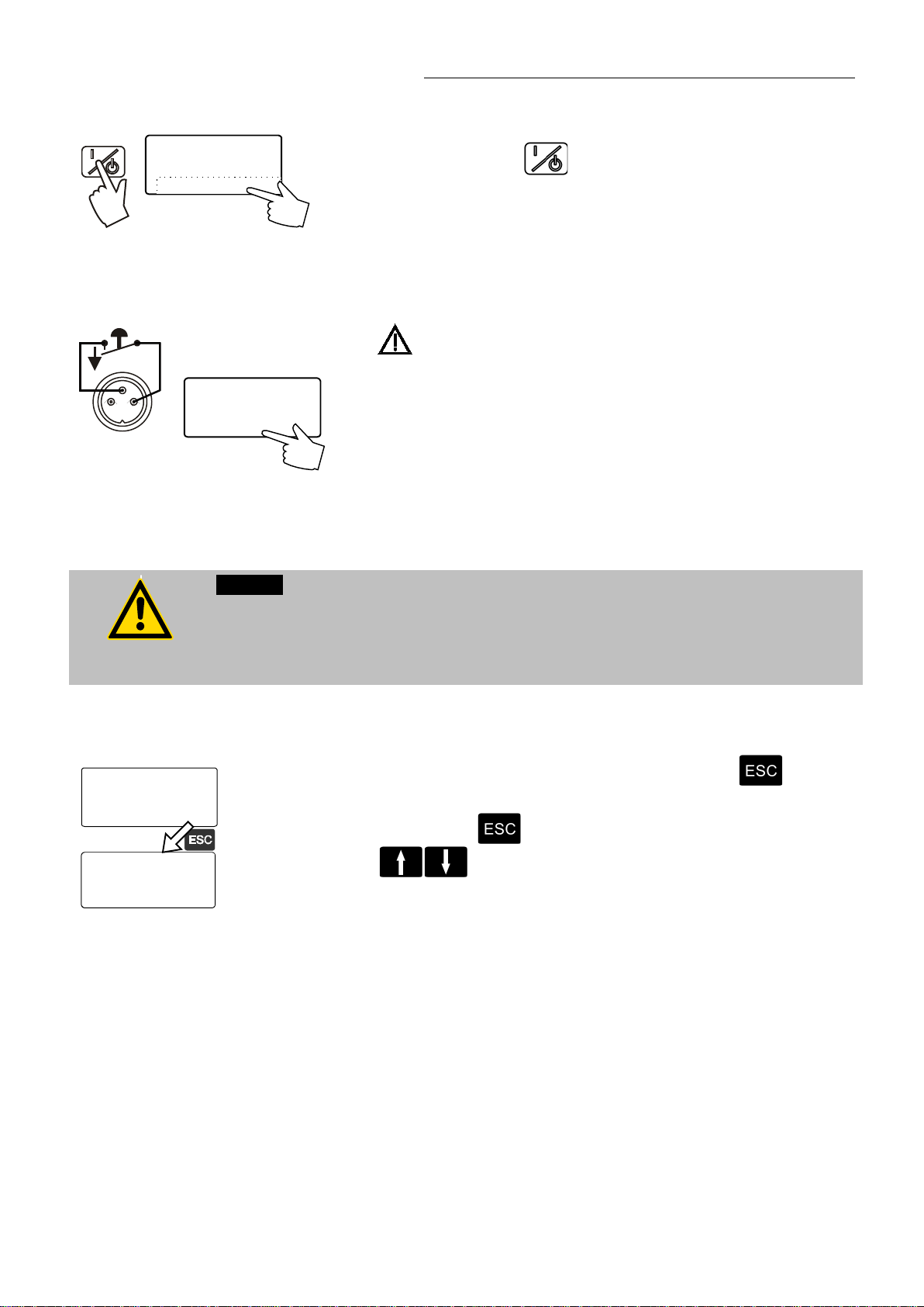
6.1. Switching on / Selecting the language
Switching on:
Turn on the mains power switch.
The unit perform s a self-test.
JULABO
HT-30/60
Controller
V 4.01-J
All segments of the 5-digit MULTI-DISPLAY (LED), all indicator lights
and the DIALOG-DISPLAY (LCD) will illuminate.
Then the software ver si on ( ex am ple: V 4.01-J) appears. The display
"OFF" indic ates the unit is ready to operate (standby mode).
The high temperatur e ci r c ulator enters the operati ng mode activated
before switching the programmable controller off:
keypad control mode (manual operation) or
remote control mode (oper ation via personal computer).
HT60-M2 / HT60-M3
Selecting the language:
There are two options for the language of the DIALOG-DISPLAY (LCD):
German or English. Select the desired language in the MENUE level
under the confi gur ation submenu.
Press the respectiv e k ey s in the following order:
1. MENUE key 1 x
2. Enter key 1 x
3. Cursor key 4 x
4. P key 1 x
5. Enter key 1 x
6. Escape key 2 x
The DIALOG-DISPLAY (LCD) helps to follow up the individual settings.
(example: swap the language from German to English.)
35
Page 36
Manual operation
The MULTI-DISPLAY (LE D) indi c ates the message "OFF".
the circulator m ay be restarted.
Setp.: 50.00°C
ExtAct: xxxxxx°C
Power xx %
Control: xxxxxx
Setp.: 230.00°C
ExtAct: xxxxxx°C
Power xx %
Control: xxxxxx
7. Manual operation
7.1. Start - Stop
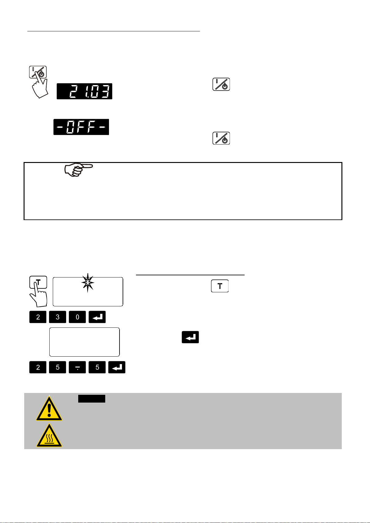
Start:
• Press the start/stop key .
The MULTI-DISPLAY (LE D) indi c ates the actual bath temperat ur e.
(example: 21.03 °C)
Stop:
• Press the start/stop key .
The unit also enters the safe operating state "OFF" or "r OFF after a
mains power interruptanc e. The temperature values enter ed v ia the
keypad remain in mem ory. With the programmable controller in k ey pad
control mode, press the start /stop key to restart operation.
With the programmable controller in remote control m ode, t he per sonal
computer must fir st r esend the par am eters set via the interface befor e
7.2. Setting the temperatures
This setting may be car ri ed out wit h the high temperature circulator being
in operating state S tart or Stop!
Setting the working temperature "T":
1. Pr ess the set point key .
The value previousl y set appear s on the DIALOG-DISPLAY (LCD)
(example: 50.00° C) .
A flashing segment indicates that a value needs to be entered.
2. Use the key pad to enter the new value (example: 230.00 °C).
3. Pr ess enter to store the selected value.
Warning:
In case of high temperat ur es some par ts of the High Temperature Circul ators can get high
surface temper atures when working continuousl y .
Attention when touching !
During operation do not touch the heating and the cooling zone.
(example 2: 25.50 ° C).
36
Page 37
7.3. Warning functions
Overtmp:240.00°C
ExtAct: xxxxxx°C
Power: x %
Control: xxxxxx
Subtemp:220.00°C
ExtAct: xxxxxx°C
Power: x %
Control: xxxxxx
)) )) ))
HT60-M2 / HT60-M3
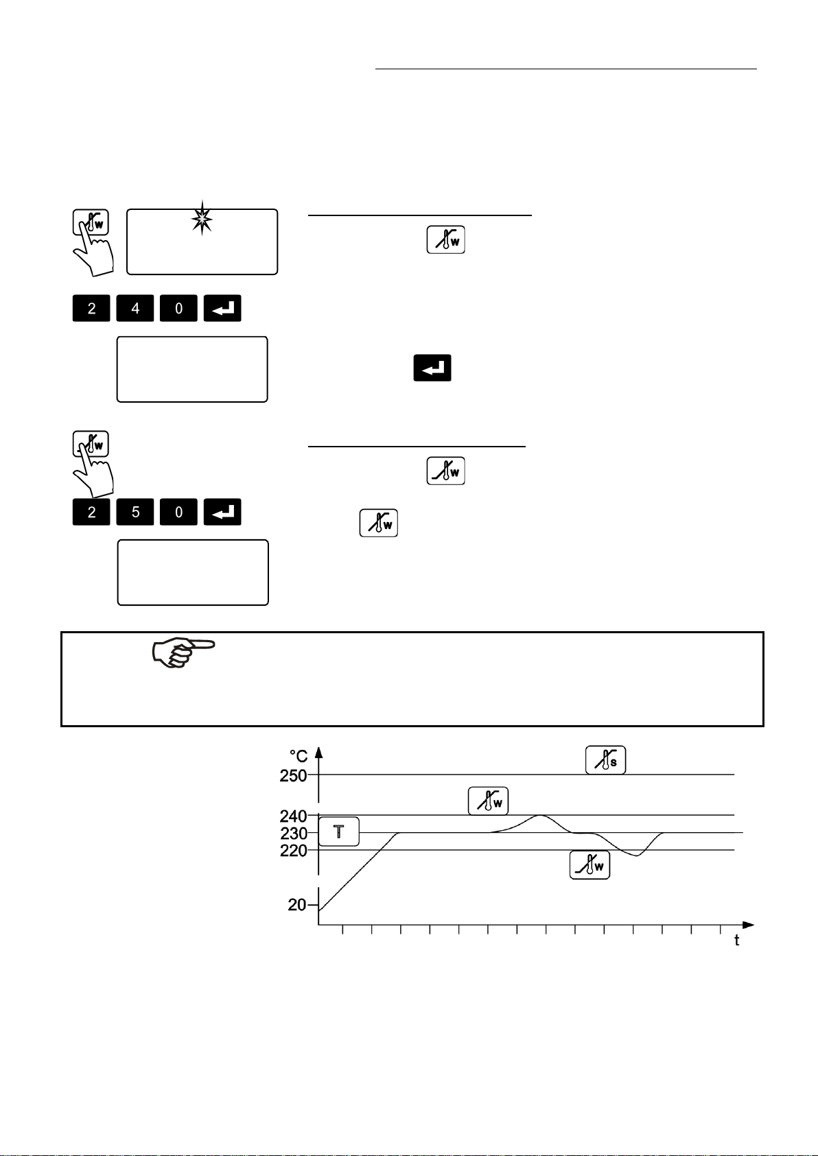
More protection for your samples in the bath!
An audible signal sounds in intervals when the actual temperature value
exceeds one of the set limits (patented).
Overtmp:305.00°C
ExtAct: xxxxxx°C
Power: x %
Control: xxxxxx
Setting the high temperature limit:
1. Pr ess the key .
The value previousl y set appeear s on the DIALOG-DISPLAY (LCD)
(example: 305.00° C) . A flashing segment indicates that a value
needs to be entered.
2. Use the key pad to enter the new value
(example: 240.00 ° C) .
3. Pr ess enter to store the value.
Setting the low temperature limit:
1. Pr ess the key .
2. F ollow the instructions
3. for ( example: 220.00 °C).
Note:
The warning functions wil l only be triggered when the actual bath
temperature, after star t f r om the „OFF “ or „rOFF “ mode, li es within the set
limits for 3 seconds.
37
Page 38
Manual operation
!
A L A R M !
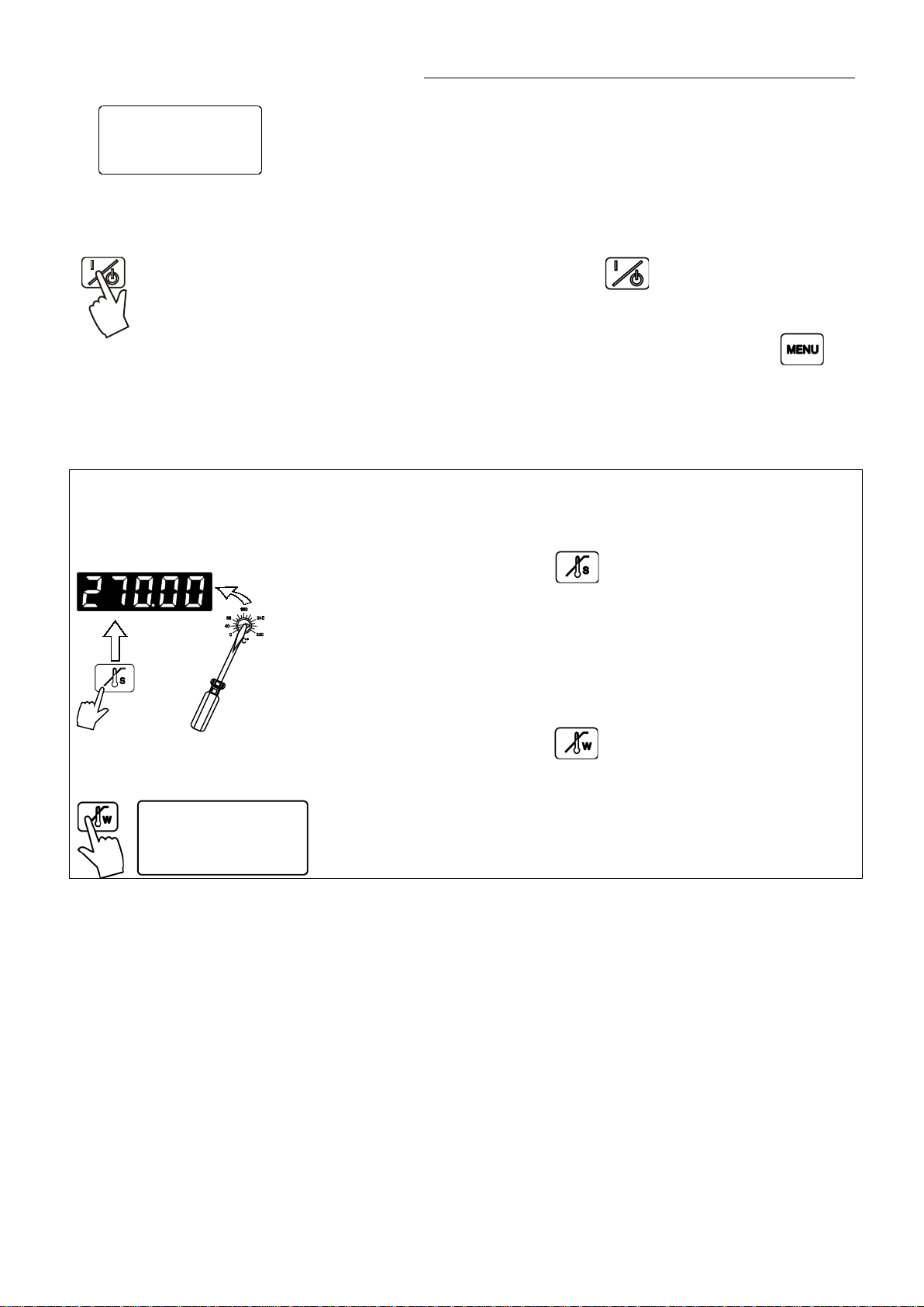
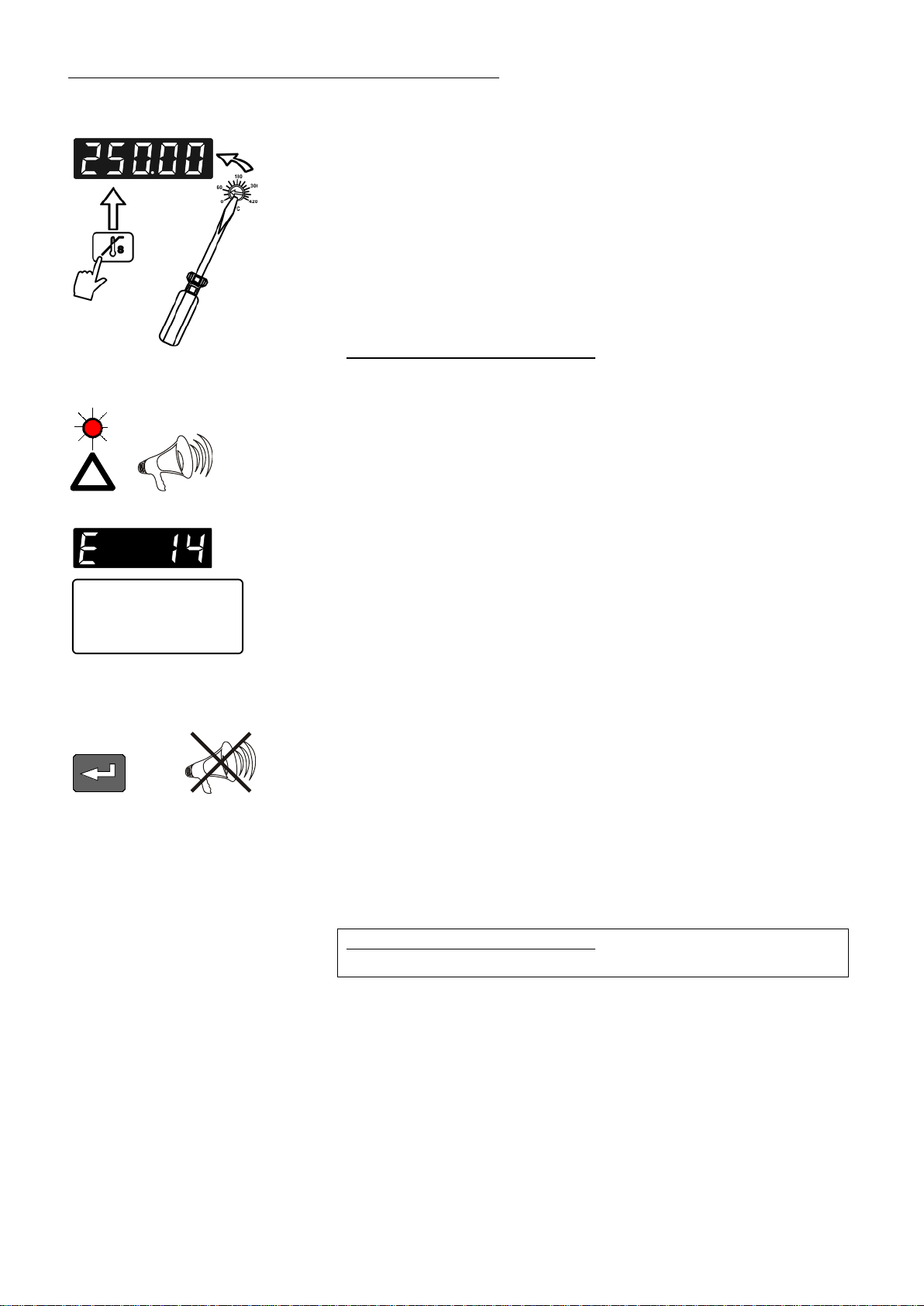
7.4. Setting the safety temperature (with shutdown function)
+
ExtAct: xxx.xx°C
Temp/level alarm
⇒
(excess temper ature protection)
• Press the key to indicate the saf ety temper ature value on the MULTIDISPLAY and using a screwdriver simultaneously t ur n the setti ng
screw to the desired value
(example: 250 °C).
Setting range: 0 °C t o 420 °C
in 2 °C steps
Safety device in the heating zone:
The safety device works independent ly from the control circuit and
supervises the temperature in the heating zone.
If the temperat ur e of the bath liquid reaches the safety temperature, a
complete shutdown of the controlled heating devic e is effected.
The alarm is indicated by optical and audible signal s (continuous tone).
On the MULTI-DISPLAY (LED) and DIALOG-DISPLAY (LCD) appears
the error message "E 14".
Cancel the alarm state (see page 60)
Recommendation:
• Set the safet y tem per ature at 20 °C above the working temperatur e
setpoint.
• From time to time the safety device has to be c hec k ed.
With a screw driver turn back the adjustable overtemperat ur e
protecti on until the shut-down point (actual tem per ature).
Safety device in the cooling zone:
See „Important noti c e“ page 28
38
Page 39

7.5. Internal / external control
Setp.1: 37.00°C
ExtAct: xxxxxx°C
Power: x %
Control: extern
Setp.: 230.00°C
ExtAct: xxxxxx°C
Power: x %
Control: intern
Setp.: 37.00°C
IntAct: 26.05°C
Power: x %
Control: xxxxxx
Setp.: 37.00°C
IntAct: 25.22°C
Power: x %
Control: xxxxxx
4
1
3
2
HT60-M2 / HT60-M3
EXT
The High Temperatur e Cir c ulator offers the possibili ty of int er nal
temperature control in a primary bath vessel or ext er nal contr ol dir ec tly in
an external system.
Setup for external control:
Connect a Pt100 sensor to the socket „ E XT“ of t he programmable
controller, if nec essary perform a calibrati on usi ng the „ATC Ext:“ function
(see 8.8. Sensors) and then securely fix the sensor in the external
system.
Switching from internal to external control:
• Press the key
type.
• The DIALOG-DISPLAY (LCD) indic ates the effective control type.
in operating state “OFF “ to sel ect the control
• Press the start/stop key .
Caution:
Place the external sensor into the bath medium and securely fix the sensor.
Temperature indication:
• Both actual temperatures are indicated at the same time:
1) on the MULTI-DISPLAY (LED)
2) on the DIALOG-DISPLAY (LCD).
• Press the key to swap the values on the displ ay s.
The indicator li ght „Ext “ r efers to the indication on the MULTIDISPLAY (LED).
39
Page 40
Menu functions
Press escape to return to the previous menu level.
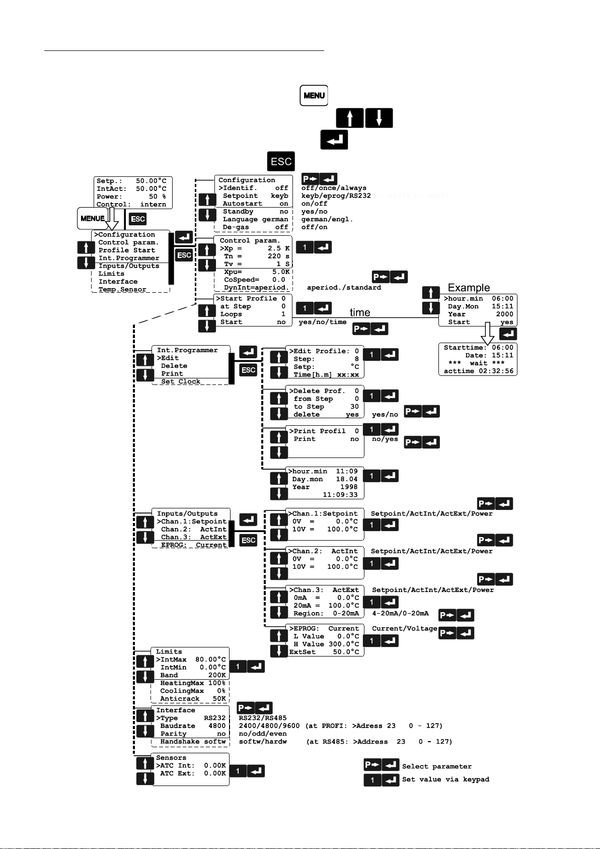
8. Menu functions
• Press the MENU key to enter the menu level.
• Use the up/down cursor keys to select the desired
submenu and press enter .
•
40
Page 41

8.1. Configuration
>Configuration
Control param.
Profile Start
Int.Programmer
Inputs/Outputs
Limits
Interface
Temp.Sensor
Configuration
>Identif. off
Setpoint keyb
Autostart on
Standby no
Language engl.
Degas off
HT60-M2 / HT60-M3
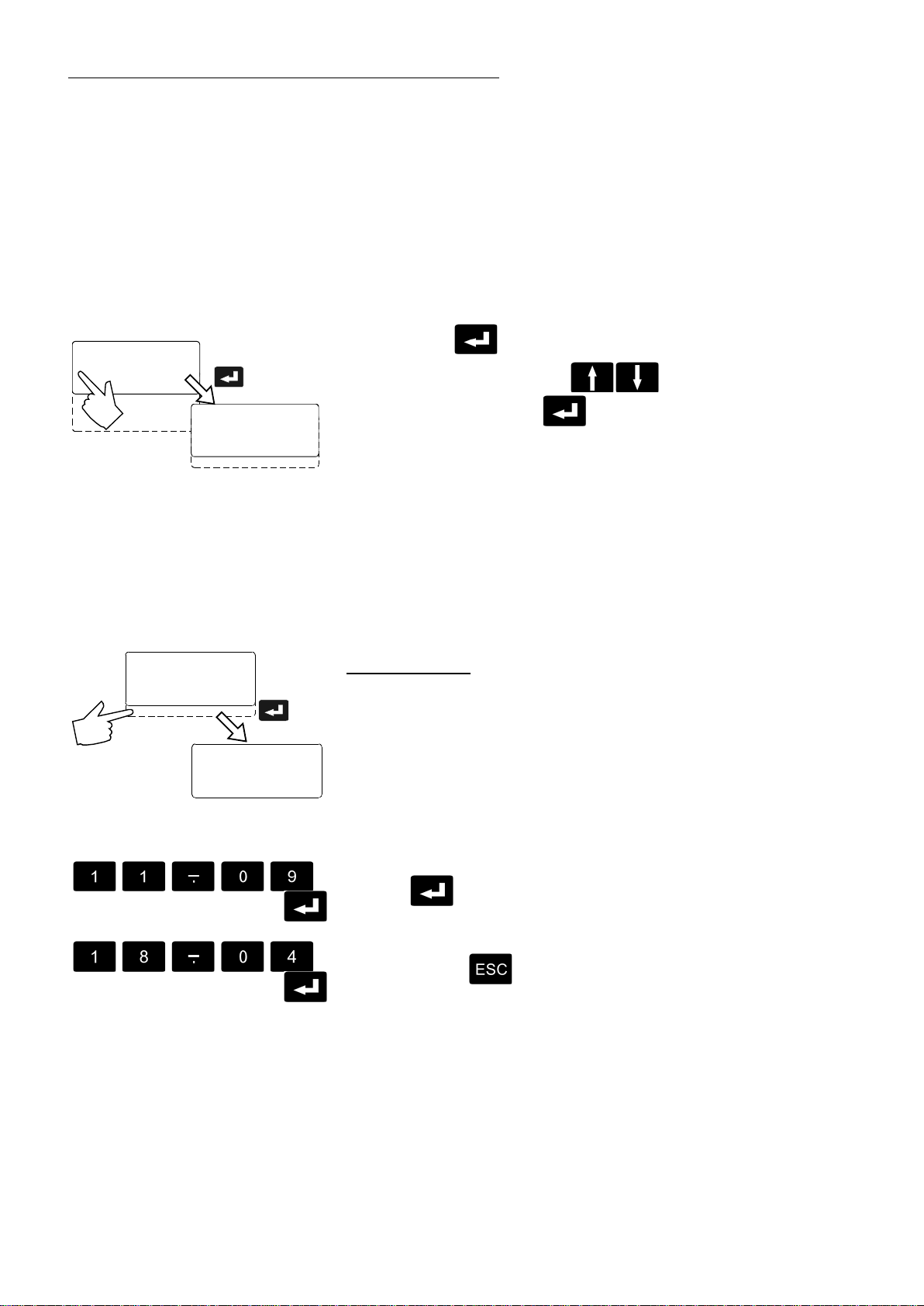
By means of the configur ation functions, operati on of t he High
Temperature Circ ulator can be optimized for the curr ent application.
• Press enter to select the configurat ion submenu.
• Use the up/down cursor keys to select the desired
option. A flashing line indicates that a value needs to be entered.
• Press the P-key t o sel ect the param eter and press enter
.
• Press escape to return the previous menu level.
Identification
When performing an ident ification for the controlled system (temperat ur e
applicati on system), the control paramet er s Xp, Tn and Tv will be
automatic ally determined and stored.
Possible parameters:
off - no identification.
The control parameters ascertained duri ng the last identification are
used for control pur poses.
once - single identification
The High Temperatur e Cir c ulator performs a single identification of
the controll ed system after start.
After the identificati on pr oc ess the parameter is automati c ally set to
“off“.
always - continual identification
The High Temperatur e Cir c ulator performs an identification of the
controlled system whenever a new setpoint is to be reached.
NOTE: Use this setting only when the tem per ature application
system changes permanent ly.
Note:
Requirement f or an identification of the contr olled system:
• The High Temperature Circulator must heat to a setpoint temperat ur e
at least 10 °C above the prev ious setpoi nt using the adjusted heating
power.
41
Page 42

Menu functions
Setp.: 50.00°C
In
Po
Co
Eprog: 50.00°C
In
Po
Co
RS232: 50.00°C
IntAct: 50.00°C
Power 50 %
Control: intern
• When the adjusted control par am eters Xp, Tn and Tv are too high,
this requirem ent may not be given with respect to on how much the
setpoint temper ature has to change. In this case, pri or to carry ing out
an identification in the „OFF“ state, set the contr ol par am eters to
lower values.
Recommended setting for internal control:
Xp = 1.0 °C
Tn = 80 s
Tv = 8 s
Setpoint
The programmabl e contr oller provides three possibilities for the setpoint
selection. The selec ted mode is indicated on the DIALOG-DISPLAY
(LCD).
Possible parameters:
keyb- via keypad (worki ng temperature T) or via the integrated
programmer.
eprog - via the analog interface REG+E-PROG (31) through an external
programmer.
REG+E-PROG
RS232 - via the serial RS 232/RS485 interface (30) through a PC or
superordinated data sy stem.
SERIAL
Autostart
Note:
The M2 / M3 control electronic has been configured and supplied by
JULABO according to N. A.M.U.R. recommendations. This means for the
start mode, that t he unit must enter a safe operating state after a power
failure (non-aut om atic start mode). This safe operati ng state is indicated
by „OFF“ or „rOFF“, resp. on the MULTI-DISPLAY (LED). A complete
shutdown of the main functional elements such as heater and circulation
pump is effected simultaneously.
Should such a safety standard not be r equired, the AUTOSTART
function (autom atic start mode) may be activated, thus allowing the start
of the programmable c ontroller directly by pressing the mains power
switch or using a tim er.
Possible parameters:
on - AUTOSTART on
off - AUTOSTART off
42
Page 43

Warning:
For supervised or unsupervised operation with the AUTOSTART function, av oid any
STAND-BY
hazardous situation to persons or propert y .
The High Temperatur e Cir c ulator does no longer conform to N.A.M.U.R. recommendations.
Take care you fully observ e the safety and warning functions of the programmable
controller.
HT60-M2 / HT60-M3
Stand-by input
External stand-by for em er genc y switc h-off
(connector - see page 6)
Possible parameters:
no - stand-by input is ignored
yes - stand-by input is active
Language
There are two options for the language of the DIALOG-DISPLAY (LCD):
German or English.
Possible parameters:
German (deutsch)
English (engl.)
Degasifying
During the filling pr oc ess the pump fluidizes air bubbl es i nto the
tempering liquid. In an automatic degasifyi ng m ode those and other light
solvent substances are let out via a breather tube.
Adjustable param eters:
off – Degasifying mode switched off
on – Degasifying mode switched on
(Also see page 32)
43
Page 44

Menu functions
Configuration
>Control param.
Profile Start
Int.Programmer
Inputs/Outputs
Limits
Interface
Temp.Sensor
Control param.
>Xp = 2.5 K
Tn = 220 s
Tv = 1 S
Xpu= 5.0K
CoSpeed= 0.0
DynInt=aperiod
8.2. Control parameters
Xp =
When performing an ident ification for the controlled system (temperatur e
applicati ons system ) ( see page 41), the control parameters Xp, Tn, and
Tv will be automatic ally determined and stored.
Each parameter may be manually set via the keypad if necessary, to
allow optimum control performance.
• Press enter to select the submenu „cont r ol par am eters“.
• Use the up/down cursor keys to select the desired
option. A flashing segment indicates that a new val ue needs to be
entered.
• Use the numeral keypad to set the value and then set with enter
(example: Xp = 2.5 °C).
• or at >DynInt<
Press the P-key to select the parameter and pr ess enter
.
• Press escape to return to the previous menu level.
Proportional range >Xp<
The proporti onal r ange is the r ange below the selected temperature
value in wich the the cont r ol ci rcuit r educ es the heating power from 100
% to 0 %.
Resetting time >Tn< (Integral component)
Compensation of the rem aining control deviati on due to proportional
regulati on. An insufficient resetting time may cause instabili ties to occur.
Excessive resett ing time will unnecessaril y prolong compensation of the
control differ enc e.
Lead time >Tv< (Differential component)
The differenti al c om ponent reduces the control settli ng time. An
insuffici ent lead time will prolong the time requir ed to compensate for
disturbance eff ec ts and cause high overshooting during run-up. An
excessive lead time could cause instabilities (oscillations) to occur .
44
Page 45

HT60-M2 / HT60-M3
JULABO
HT-30/60
Controller
V 4.01-J
Note:
The parameters >Xpu<, >CoSpeed< and >Dynamik< are only
supported from the programme version V4 xx.
If the control electronics (V 4.xx) M2 respectively M3 is
combined with an older v er si on of t he HT60 cir c ulators, these
parameters are not av ailable. They are not indicated in the
menu.
Proportional range >Xpu<
The proporti onal r ange Xpu of the cascaded controller is only
needed for external control.
>DynInt< - Dynamics
This parameter aff ec ts the march of temperature only in case
of internal control ( see page 39).
Adjustable param eter:
standard The t em per ature rises quicker, howev er can
overshoot up to 5 %. If a ramp is defined, the
march of temperatur e oft en follows this ramp.
aperiod. The temperature rises chronologically without
overshoot.
With both adjustment s a sufficient temperatur e stability is
reached after approx imately the same time.
>CoSpeed< 0 up to 5
This parameter aff ec ts the march temperature only in case of
external control ( see page 39).
The adjustment aff ec ts the calculation of the control parameter
when identifying and so the c ontrol course.
45
Page 46

Menu functions
°C
t
heat-up curves:
°C
t
°C
t
°C
t
°C
t
Optimization instructions for the PID control parameters:
The heat-up curve r ev eals i nappr opr iate control settings.
(example: working t em per ature T)
optimum setti ng
Inappropriat e settings may produce the following
Xp too low
Tv/Tn too low
Xp too high
or
Tv too high
Tv/Tn too high
or
Xp too high
46
Page 47

8.3. Start of a profile
Configuration
>Identif. off
Setpoint keyb
Autostart on
Configuration
Control param.
Profile Start
Int.Programmer
Inputs/Outputs
Limits
Interface
Temp.Sensor
Start Profile 0
at Step 0
Loops 1
>Start time
>hour.min 06:00
Day.Mon 15:11
Year 2000
Start yes
HT60-M2 / HT60-M3
1.
2.
The start menu of the High Temperature Circulator allows cal ling up and
defined starting of one of six previously stored t em per ature pr ofiles. This
start can be effected m anually or be released by an integrated timer.
Important:
In the menu configuration under menu point „setpoint“ operation has t o
be set via „key“.
There are two possibilities for manually starting a program:
1. Starting a program from the OFF stat us:
The programmer switches back to the OFF status at the end of the
program.
2. Starting a program from the operating status.
The programmer is started with the Start key , and the bath is
heated to the desired temperature, for example 100 ° C. At the end of
the program, the programmer switches to the operating status and
holds the bath temper ature stable at 100.00 °C.
• Press enter to select the submenu „Profile Start“.
• Use the up/down cursor keys
to select the desired
option.
A flashing segment indicates that a number needs to be entered.
Start Profile 0 to 5
at Step 0 to 60
Loops 1 to 99
Enter the desired num ber and set eac h entry with enter .
Start no / yes (manual start)
or
time (via integrated timer)
A flashing line indicates that a parameter needs to be enter ed.
Press the P-key to select the respectiv e par am eter and press
enter .
47
Page 48

Menu functions
>hour.min 06:00
Day.Mon 15:11
Year 2000
Start yes
Starttime: 06:00
Date: 15:11
*** wait ***
acttime 02:32:56
Setp. : xx.xx°C
IntAct: xx.xx°C
Prof. : x Stp: x
Remain: xx:xx:xx
Setp. : xx.xx°C
ExtAct: xx.xx°C
Prof. : x Stp: x
Remain: xx:xx:xx
Example: hour.mi n 6:00 h
• When selecting the paramet er time, a new menu level is called up
for entry of the start time.
A flashing segment indicates that a start time needs to be entered.
hour.min Start time
Day.Mon day and month
Year year
Set each entry with ent er .
Start no / yes
A flashing line indicates that the parameter „y es“ needs to be
entered.
Press the P-key to select the parameter and pr ess enter
.
• The High Temperature Circulator switches to waiting mode and a
flashing li ne „wait“ appear s on the DIALOG-DISPLAY (LCD). The
start time and act ual time ar e permanently indicated on the display.
Indication after starting the profile:
DIALOG-DISPLAY (LCD)
1st line: Setpoint of the programmer
2nd line: Actual temperature value
at internal control = IntAct: xxx.xx
at external control = ExtAct: xxx.xx
3rd line: Selected profile and the actual section
4th line: Rem aining time of the actual section
MULTI-DISPLAY (LED)
If the circulator is operat ed through the integrated programmer the
MULTI-DISPLAY (LED) swaps between the two actual values
(internal and external)
48
Page 49
8.3.1. Interrupting a profile
flashes on the DIALOG DISPLA Y (LCD).
Setp. : xx.xx°C
IntAct: xx.xx°C
Prof. : x Stp: x
** STAND-BY **
>Start Profile 0
at Step 0
Loops 1
Start yes
Setp. : xx.xx°C
IntAct: xx.xx°C
Prof. : x Stp: x
Remain: xx:xx:xx
AK 1 2 3 STAND-BY
HT60-M2 / HT60-M3
Setp. : xx.xx°C
IntAct: xx.xx°C
Prof. : x Stp: x
Remain: xx:xx:xx
*** pause ***
Interrupting a profile:
Press the start/stop key to interrupt or restart a profile.
The setpoint and time period set for the corresponding secti on ar e thus
stopped at the values presently achieved.
The programmabl e contr oller is put on hold and the message „pause“
• A profile can be interrupted or restarted by an external emergenc y
shut-off.(see page 6).
CAUTION:
This is not an actual emergency shut-off!
• The setpoint control and the timer are interrupted by breaking the
contact “AK”. The pr ogr ammer switches to the waiting position, while
displaying this condition with a blinking LCD displ ay .
Important:
To achieve this, the Stand-by c ondition must first be activ ated and
the Autostart function turned on.
(see page 43).
Warning:
Following a power inter r uption, it would be possible in thi s condition for the programmer to
restart automati c ally. The safety and warning functions of the programmer should always be
used to their fullest c apac ity.
See warning page 43
Termination of a profile:
A profile can be termi nated by pressing the escape key . The
programmer switches back to the Start menu.
• Press escape again to leave the menu or use the cursor keys
to remain in the Start menu.
The execution of another temperature profile can now be prepared if
necessary.
49
Page 50
Menu functions
Control param.
Profile Start
Int.Programmer
Inputs/Outputs
Limits
Interface
Temp.Sensor
Int.Programmer
>Edit
Delete
Print
Set Clock
Int.Programmer
Edit
Delete
Print
>Set Clock
>hour.min 11:09
Day.mon 18.04
Year 2001
11:09:33
8.4. Integrated programmer
The integrated progr ammer allows any desired temperat ur e pr ogr am
sequences to be reali z ed. Suc h a temper ature sequence is called
profile. A profil e c onsi sts of individual sections defi ned by durat ion (t:)
and target temperature. Target temperature is the setpoint (T:), that is
achieved at the end of a secti on. T he pr ogr ammer uses time and
temperature dif ference values within a section to calculate a
temperature ram p.
• Press enter to selec t th e submenu „Int. Programmer“.
• Use de up/down cursor keys t o sel ec t the desired
option. Then press enter to open.
A flashing segment indicates that a number or value needs to be
entered.
Edit Compile profiles
Display secti ons
Delete Delet e sect ions
Print Print a programmed profile
Set clock Set the real time on the programmable
controller
Examples:
Setting the clock
The integrated cloc k pr ov ides the flexibility to start a profile at any date
and time. The clock is preset at the JULABO factory.
• Lines 1 to 3:
Check for correctness of the preset date and time and correct if
necessary.
The time is diplayed perm anently in line 4.
• Use the numerals to set time, date and year and set each entr y with
enter .
• Press escape to return to the previous menu level.
50
Page 51
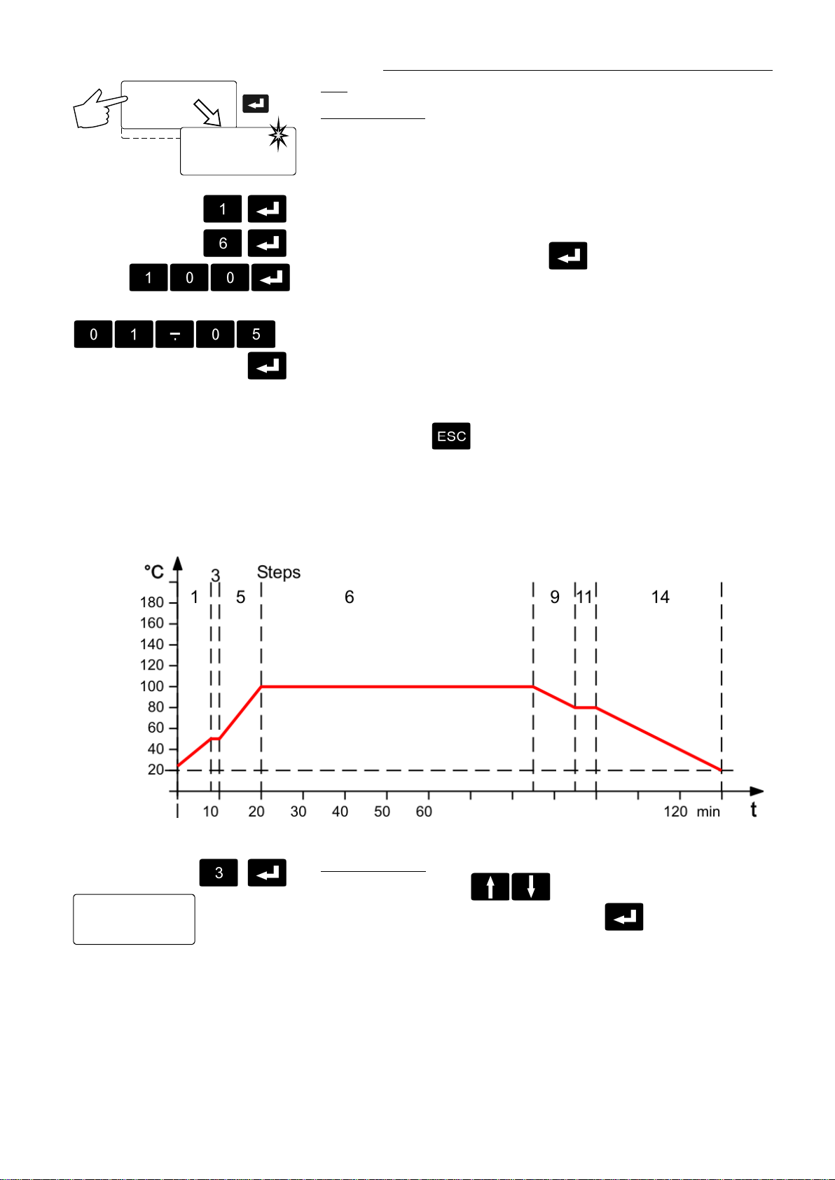
HT60-M2 / HT60-M3
Int.Programmer
Time[h.m] 01:05
Edit Profile: 1
Time[h.m] 00:02
The values previously set are displayed.
>Edit
Delete
Print
Set Clock
>Edit Profile: 1
Step: 6
Setp: 100.00°C
Examples:
Profile No. 1
Compile profiles:
• A flashing segment indic ates that a num ber needs to be entered.
Under submenu „Edit Pr ofile“ enter a profile number.
Six profiles may be stor ed ( nos. 0 to 5).
• Then programme the desired values for eac h sect ion.
Use the keypad to set section num ber , target temperature and time
Step
period. Set each ent r y with enter .
Edit
Setpoint
Time
When the program is runni ng, only sections having complet e
informati on for target temperature and time peri od ar e considered.
It makes sense, to leave out section numbers in the profile, i n order
to use them later for corr ections in the profile.
Important:
If a time of 00:00 is set for a profile, t he pr ofile is continued with the
next section only aft er the setpoint temperature (± 0.2 °C) is reached.
• Press escape to return to the previous menu level.
Example:
Step (No.) 1 3 5 6 9 11 14
Setpoint (°C) 50 50 100 100 80 80 20
Time (h:m) 00:08 00:02 00:10 01:05 00:10 00:05 00:30
Step
>Step: 3
Setp: 50:00°C
Display secti ons:
• Use the cursor keys t o sel ect the submenu „Step“,
enter the desired number and pr ess enter .
•
51
Page 52
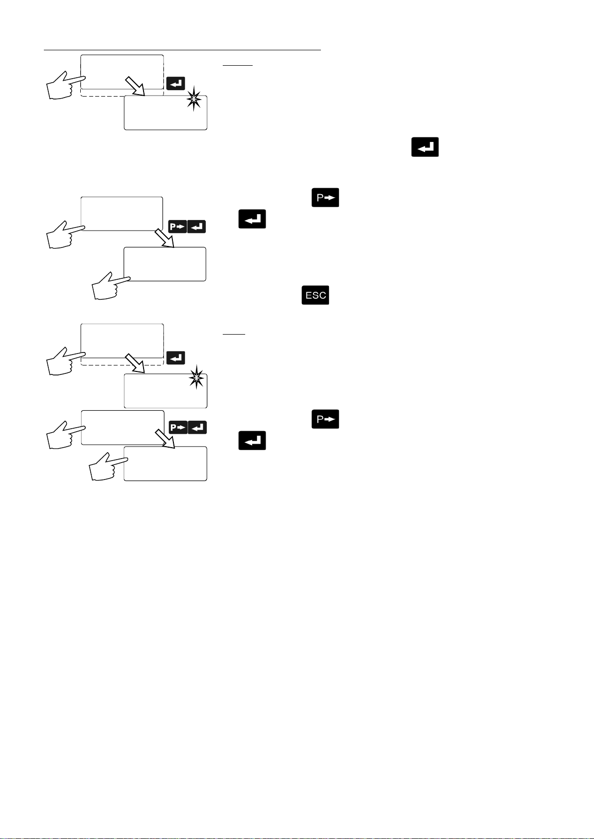
Menu functions
Int.Programmer
Edit
>Delete
Print
Set Clock
>Delete Prof. 0
from Step 0
to Step 00
delete no
Delete Prof. 3
from Step 8
to Step 34
****delete****
Delete Prof. 3
from Step 8
to Step 34
>delete yes
Int.Programmer
Edit
Delete
>Print
Set Clock
>Print Profil 0
Print no
Print Profil 2
>Print yes
Print Profil 2
****print****
etc.
Delete
• A flashing segment indic ates that the respective profile number
needs to be entered in which one or m or e consecutive sections are
to be deleted.
• In lines 2 and 3 of the DIALOG DISPLAY (LCD) enter the numbers of
the sections to be del eted. P r ess enter .
• delete no / yes
Press the P-key to select the parameter „ y es“ and press enter
.
Line 4 indicat es the deletion.
Example:
Delete secti on 8 to section 34 in pr ofile 3.
• Press escape to return to the previous menu level.
Print
Each profile may be printed via the serial interfac e for contr ol or
documentation.
• A flashing segment indic ates that the number of the profile to be
printed needs to be enter ed.
• Print no / yes
Profile 1
Step 0 not defined!
Step 1 50 00:08
Step 2 not defined!
Step 3 50 00:02
Step 4 not defined!
Step 5 100 00:10
Step 6 100 01:05
Step 7 not defined!
Step 8 not defined!
Step 9 80 00:10
Step 10 not defi ned!
Step 11 80 00:05
Step 12 not defined!
Step 13 not defined!
Step 14 20 00:30
Step 15 not defined!
Press the P-key to select the parameter „ y es“ and press enter
.
Printing is indicated in line 2.
This printi ng example shows the profile given as example on page 51.
52
Page 53
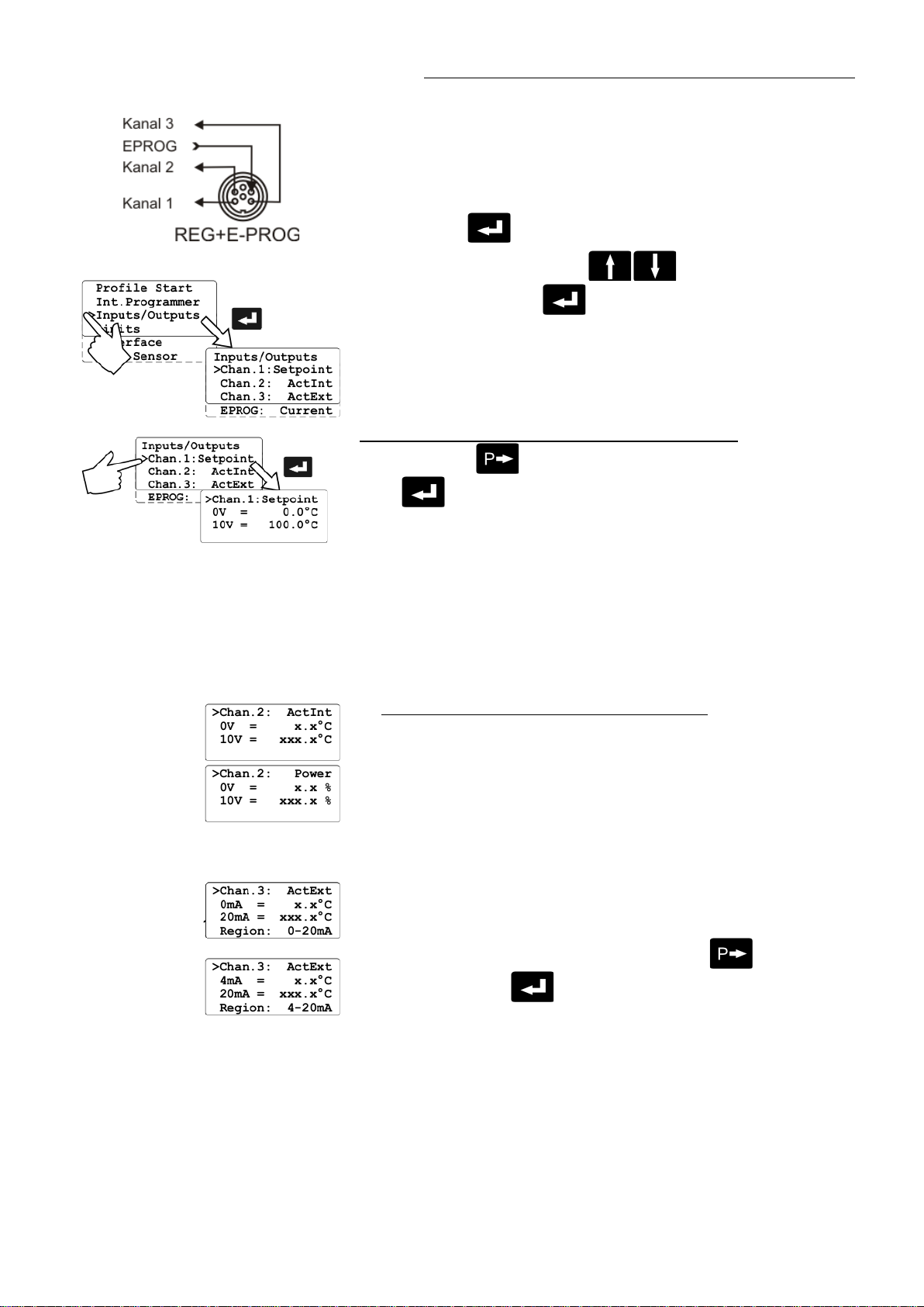
8.5. Analog inputs/outputs
HT60-M2 / HT60-M3
This submenu enables setting of the input and output values for the
programmer input and t he temperature recorder out puts of socket
REG+E-PROG (31).
or
• Press enter to select the inputs/outputs submenu.
• Use the up/down cursor keys to select the desired
option and press enter to open.
Chan.1 voltage output for recorder (V)
Chan.2 voltage output for recorder (V)
Chan.3 current output for recorder (mA)
EPROG external programmer input
First define the desir ed output value for channels 1 to 3:
Press the P-key to select the desired output v alue and set with
enter
Setpoint active setpoint temperature
(T, i ntegr. programmer/ext. progr ammer)
ActInt internal actual temperature value
(bath t em per ature)
ActExt external actual temperature value
(exter nal sensor)
Power periodi c or int ermittent heating or cooling
• Then select the display siz e for channel s 1 to 3:
Channel 1 and 2 voltage outputs
Assign the voltage v alues of 0 V to the lowest and 10 V to the
highest necessary temperature or power rati ng r equired as an
output value (°C or %).
Current output channel 3
Assign the current values 0 mA or 4 mA to the lowest and 20 mA to
the hightest t em per ature or power rat ing required as an output value
(°C or %).
The current out put offer s 2 ranges for selection:
0 to 20 mA and 4 to 20 mA.
Select the desired r ange by pr essing t he P-key
and set with enter
The LCD display changes autom atically.
.
53
Page 54
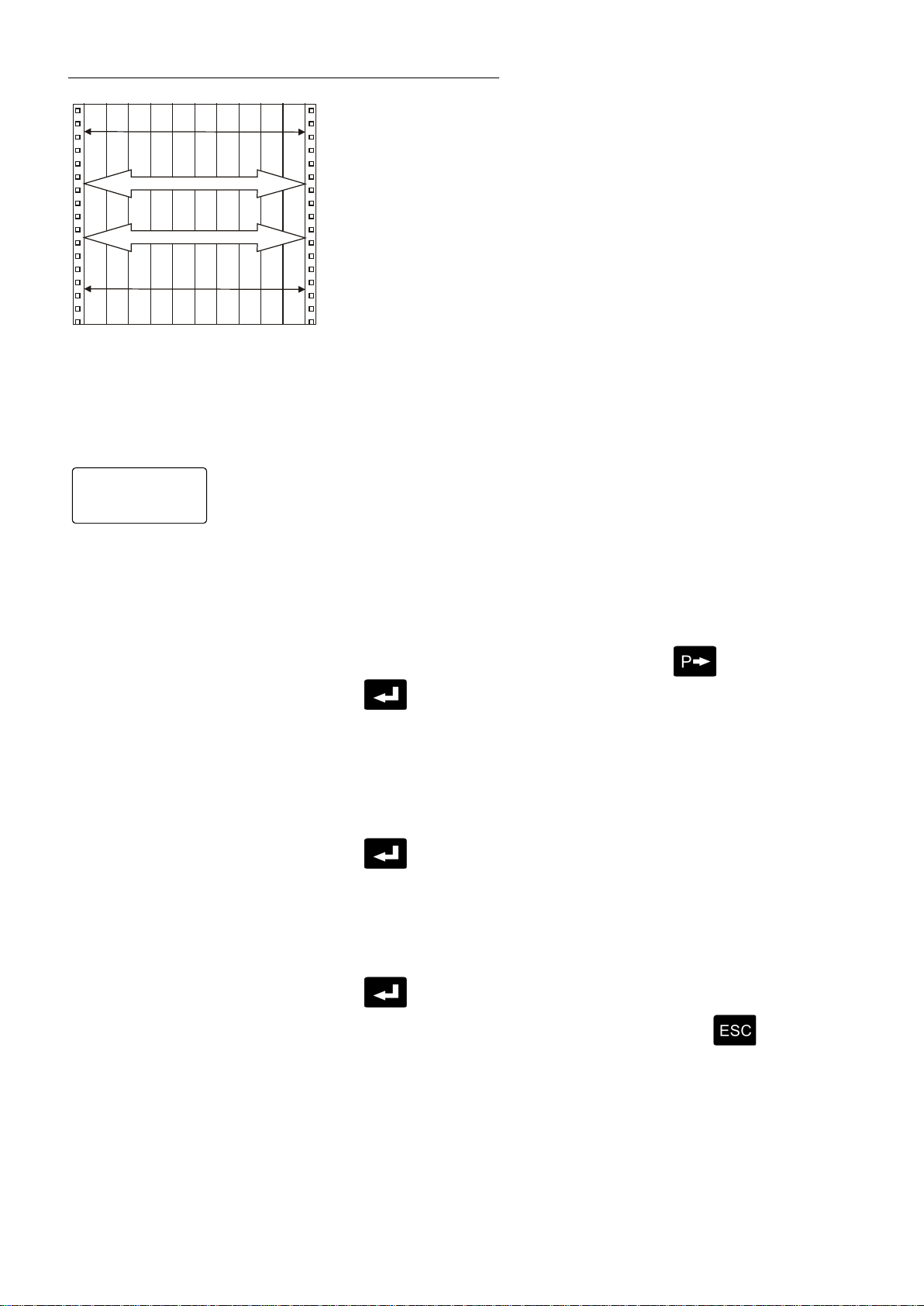
Menu functions
>EPROG: Current
ExtSet 50.0°C
0 V
0 mA
20 mA
4 mA
10 °C 210 °C
197 °C 202 °C
∆ Τ = 5 K
∆ Τ = 200 K
L Value 0.0°C
H Value 300.0°C
Examples:
lowest temperat ur e value: 10 °C
highest temperature value 210 °C
Fig. shows 200 °C scaled to paper width
rise: 50 mV/°C
lowest temperature value: 197 °C
highest temperature value: 202 °C
Fig. shows 5 °C scaled to paper width
rise: 2000 mV/°C
EPROG - Input
This input is necessary when the nominal value is to be determined and
set by an external programm er .
Connect the exter nal pr ogr ammer to socket (31)
REG+E-PROG of the programmable controller.
• The programmer input of the progr ammable controller can be
matched to the output si gnal of t he exter nal programmer.
Voltage voltage input
Current current input
Select the desired input value with the P-key and set wi th enter
.
• „L Value“ - Setting the LOW value::
Adjust and set the lowest desired working temperature on the
programmer (e.g. 0 °C).
Enter this same tem per ature on the programmable controll er by
pressing the appropriate buttons on the keypad and press enter
to set.
• „H Value“ - Setting the HIGH value:
Adjust and set the hi ghest desi r ed working temperature on the
programmer (e.g. 300 °C).
Enter this same tem per ature on the programmable controll er by
pressing the appropriate buttons on the keypad and press enter
to set.
• Return to the standard display by pr essing escape
.
54
Page 55

HT60-M2 / HT60-M3
>EPROG: Current
L Value 0.0°C
H Value 300.0°C
ExtSet 50.0°C
EPROG : 50.00°C
IntAct: 50.00°C
Power: 50 %
Control: intern
3x
Control: intern
>EPROG: Current
20
40
60
80
100
200
300
250
150
°C
1 2 3 4 5 6 7 8 9 10 V
2 4 6810 14 18 20 mA
A
B
Example:
• Setting a temperature of 50 °C on the external pr ogr ammer!
The value adjusted and set on the ex ternal programmer is displ ay ed in
line 4 of the DIALOG-DISP LAY (LCD) for c ontrol pur poses (Example:
ExtSet: 50.0 °C).
After returning the LCD display to standar d display by pressing escape
(„Setpoint“ - see page 42) this value is displayed in line 1
(Example: EPROG 50.00 °C).
This EPROG input enables the use of different voltage and current
values as program parameters.
• „L Value“ - Setting the LOW value:
1) Adjust and set the lowest desir ed value on the voltage or current
source resp. (Example A: 1 V).
2) Assign a lower temper ature threshold value to this adjusted
voltage/current value by pressing the appropriate buttons on the
keypad of the programmable controller (Example A: 20 °C ) and set
by pressing enter
.
• „H Value“ - Setting the HIGH value:
1) Adjust and set the highest desir ed value on the voltage or current
source resp. (Exam ple A: 10 V).
2) Assign an upper temper ature threshold value to this adjusted
voltage/current value by pressing the appropr iate buttons on the
keypad of the programmable controller
L Value 20.0°C
H Value 200.0°C
ExtSet 152.0°C
(Example A: 200 °C) and set by pressing ent er .
• Return to the standard display by pr essing escape .
Example B in the diagram serves to illustrate that the end point values
are freely selectable.
Example out of diagram A:
• Adjusting the voltage source for an output of 7.6 V!
Line 4 of the DIALOG-DISPLAY ( LCD) shows the ext ernal ly set setpoint
value. The programm able controller calcul ates this value from the rise
3x
EPROG : 152.00°C
IntAct: 50.00°C
Power: 100 %
angle of the two predecided end points (in example A: 7.6 V correspond
to an external setpoi nt temperature of 152.0 °C ).
After returning the LCD display to standard displ ay by pressing escape
, this value is displayed in line 1
(Example: EPROG 152.00 °C).
Notice:
If this adjustment is not correctly performed at two different points, the setpoint setting will be
incorrect.
55
Page 56
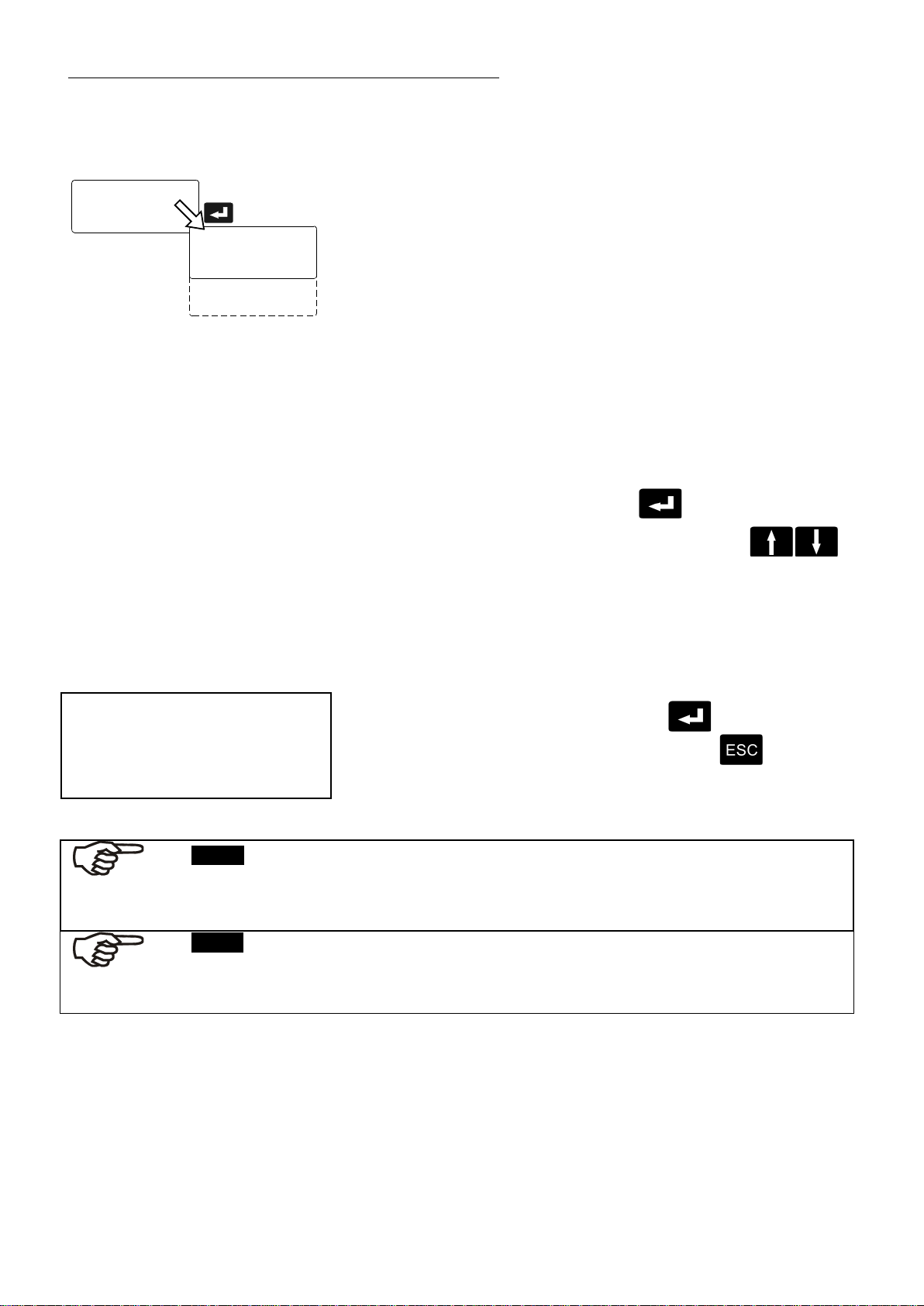
Menu functions
Inputs/Outputs
>Limits
Interface
Temp.Sensor
Limits
>IntMax 80.00°C
IntMin 0.00°C
Band 30K
HeatingMax 100%
CoolingMax 0%
Anticrack 50K
circulator , t hese parameters are not available. They will not be indi c ated in the menu.
8.6. Limits
Factory setti ngs:
Band 200 K
HeatingMax 100 %
CoolingMax0
Anticrack 30 K
The limits IntMax and IntMin are only valid under external control (see
7.5. Internal / external cont r ol) They restrict the temperature of the
internal bath to t he desi r ed m aximum/minimum, also if the controll er
would require a higher /lower temperature for the exter nal system. As a
result the ext er nal setpoint may thus not be reached.
When operating the progr ammable controller under ex ternal control,
band limiti ng is active. The preset value determines the m ax im um
temperature dif ference between the internal bat h and the external load.
This adjustment possibility prevents sensitive equipment and
temperature devic es fr om dam age.
The limitation „Cr ac k pr otection“ shall avoid a partial overheating of the
stil l thick -flowing temperat ur e liquid after switching on the cir c ulator.
Heating and cooli ng power of the programmable control ler are
adjustable.
100 % corresponds to the values in the technical specifi c ations of the
equipment.
• Select the submenu „Limit s“ wit h enter .
• Select the desired option wit h the up/ down cursor keys .
A flashing digit indic ates that a value needs to be entered.
IntMax see working tem per ature range page 13
IntMin see working temper ature range
Band 0 t o 200 ° C
HeatingMax 0 to 100 % in steps of 1 %
CoolingMax 0 to 100 % in steps of 1 %
Anticrack 30 K t o 100 K
• To set the newly entered value press enter .
• To return to the previous menu level press escape .
Notice: - CoolingMax –
The assembled C.U. -cooli ng unit the menu point CoolingMax has to be set to a value >0
(Recommendati on: 100%). So the automatic control of the cooling can become active.
Notice:
The parameters >IntMax< and >IntMin< are only supported from programme version V°4.xx
on. If the control el ectr onics (V 4.xx) M2 / M3 is combined with an older v er si on of the HT60
56
Page 57
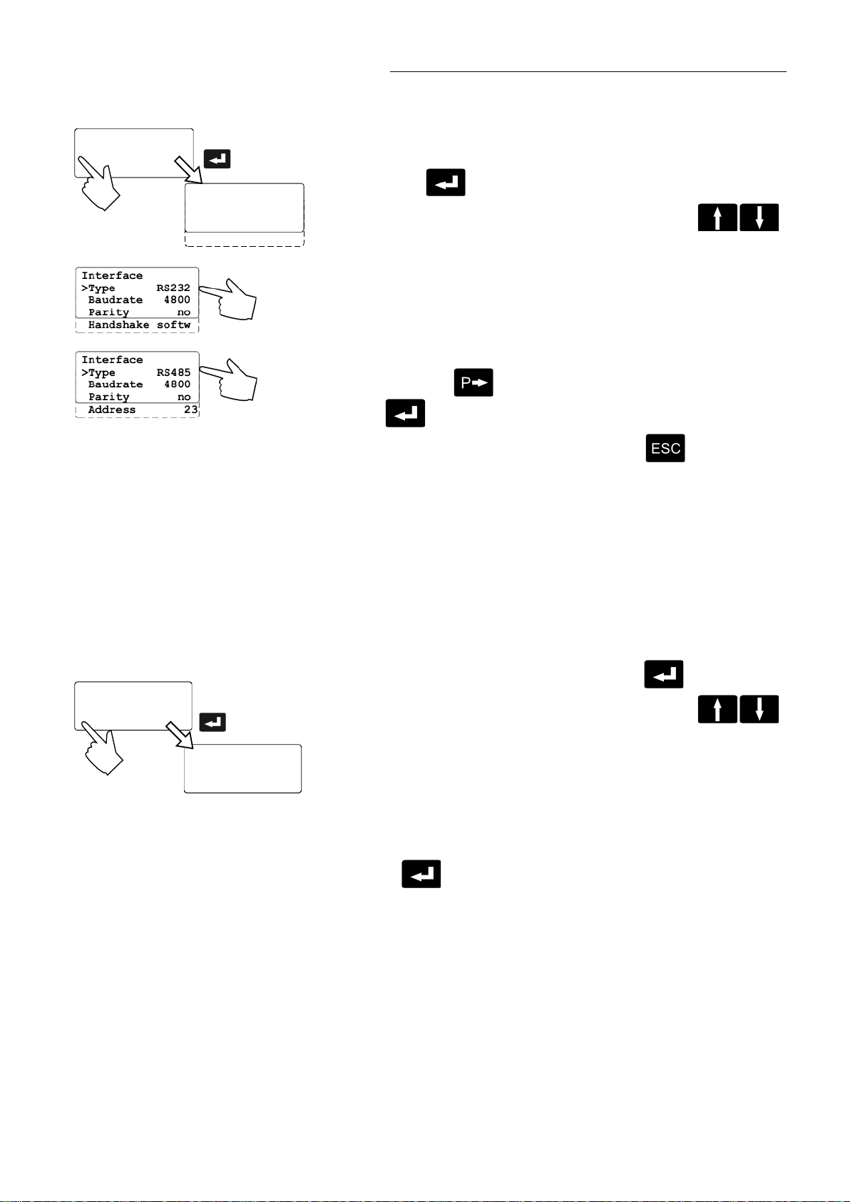
8.7. Interface
Interface
>Type RS232
Baudrate 4800
Parity no
Handshake softw
Inputs/Outputs
Limits
>Interface
Temp.Sensor
Sensors
>ATC Int: 0.00K
ATC Ext: 0.00K
Inputs/Outputs
Limits
Interface
>Temp.Sensor
HT60-M2 / HT60-M3
The interface par am eters are set by selecting the submenu „Int erface“
on the programmabl e contr oller. Normally, this is a one-time-only
adjustment.
• Press enter to select the submenu „Interface“.
• Select the desired option wit h the up/ down cursor keys
Enter the desired v alue for the flashing digit.
Type RS232 / RS485
.
Baudrate 2400/4800/9600
Parity none/even/odd
Handshake software handshake/hardware handshake
Address 0 to 127
• Press the P-key t o sel ect the desir ed par ameter and set with
enter
• Return to the previous menu lev el with escape
.
.
Factory setti ngs
see - 11.1.
8.8. Sensors
ATC - Absolute Temperature Calibration
• Select the submenu „Temp.S ensor“ with enter .
• Select the desired option wit h the up/ down cursor keys
A flashing digit indic ates that a value needs to be entered i. e. set.
ATC Int: i nternal sensor
ATC Ext: external sensor
Maximum setti ng ±9.99 K
• Enter the desired compensating value and set this value by pressing
ENTER
.
57
Page 58

Menu functions
Sensors
>ATC Int: -0.80K
ATC Ext: 0.00K
Setp.: 50.00°C
ExtAct: 51.22°C
Power: 100 %
Control: intern
Sensors
>ATC Int: -0.80K
ATC Ext: 1.22K
Circulator (TT)
Measuring point (T
ATC Int:
ATC serves to compensate a temper ature difference that might oc c ur
between circulator and a defined measuring point in the bath tank
because of physical proper ties.
)
M
• The difference temperatur e (∆T = T
compensating value (example ∆T = -0.8 °C).
• Use the keypad to enter the desired compensating value
(e.g. -0.80) and set with enter .
• The temperature on the measuring point rises to a temperature of
50.0 °C and is indicated on the MULTI-DISPLAY (LED).
- TT) is determined and stored as
M
ext. Pt100
Circulator (T
External sensor (T
)
T
Pt100
Note:
The compensating f actor always affects the actual working t em perature,
even when set via the int erfac e c onnec tion.
ATC Ext:
serves calibr ation of an external Pt100 sensor.
• Immerse the Pt100 sensor in the circulator bath tank and allow the
bath temperatur e to stabilize at 50 °C, for example.
• Read the temperatures of the factory calibrated circulator (T
external Pt100 sensor (T
• Calculate the temperatur e difference and enter and set this diff er enc e
value as the ATC external c om pensating parameter.
(Example: ∆T = T
• Use the keypad to enter the desired compensating value
)
(e.g. 1.22 °C) and set wit h enter .
- TT = 1.22 °C)
Pt100
) in their respect ive displays.
Pt100
) and the
T
58
Notice:
The ATC function remains active until reset to 00.00 °C.
Page 59

9. Troubleshooting guide / Error messages
!
• The cooling water temperat ur e v alue lies bel ow 5 °C.
more than 100 K.
Set the safety temper ature to a higher value.
Whenever the micr opr oc essor elec tronics registers a f ailure, a complete shutdown
HT60-M2 / HT60-M3
+
of the circulat or i s perf ormed. The alarm light "
signal tone sounds.
• The circulator is operated without bath liquid, or the liquid level is insufficient.
Replenish the bath tank with the bath liquid.
• Tube breakage has occured (insufficient filling level due to excessive bath
liquid pumped out ). Replace the tubing and replenish the bath t ank with the
bath liquid.
• The float is defect (e. g., because damaged in transit). Repair by authori z ed
JULABO service personnel.
• Failure of one or both temperatur e sensors of the CU-unit.
• Cable of the working temperat ur e sensor interrupted or short-circuited.
• Defect of the working or safety tem per ature sensor.
Working temperature and safety sensors report a temperature differenc e of
• Other errors (I2C-BUS errors)
" illuminates and a continuous
• Error in A/D converter.
• Safety sensor defect.
• The safety temperature value lies below the working temperature setpoint.
• External control selected, but external Pt100 sensor not c onnec ted.
• Error in the measuring system of the external temperature sensor „EXT“.
• Error at the internal Interf ac e
• Safety sensor 1:
Cable of the safety sensor 1 int er r upted or short-circuited.
• Safety sensor 2:
Cable of the safety sensor 2 int er r upted or short-circuited.
• Safety sensor 3:
Cable of the safety sensor 3 int er r upted or short-circuited.
59
Page 60

Troubleshooting guide / Error messages
exceeded 170 °C. See „Impor tant notice“ Page 28.
Only use fine fuses with a nominal value as specified.
Manufacturer
Supplier
Type
Order No.
T16A 5x20mm
60
30
1545
4 s
4
A
M
P
• Safety sensor in the cooling zone:
Cable of the safety sensor int er r upted or short-circuited.
• Safety sensor in the cooling zone: The t em per ature in the cooling zone has
• Press enter
⇒
to quit the audible signal.
After eliminati ng the malfunction, press the m ains power switch off and on again to
cancel the alarm state.
• If the unit cannot be returned to oper ation, contact an authorized JULA BO
service stati on.
Mains Fuses M2, M3:
16
A
M
P
• Mains circuit breakers (resett able) for the circulator (16 A) and
the CU-unit (4 A) on the rear of the housing are safety machines.
Mains Fuses M2:
The mains fuses (36) on the rear of the unit m ay easily be exchanged as shown
on the left – T 16 A.
Warning:
Before exchangi ng the fuses, turn off the mains power switch and disconnect the power plug
from the mains socket!
Example:
Schurter Schurter G-fuse insert SPT
60
No. 0001.2516
Page 61

10. Electrical connections
The shield of the connecting cable is electricall y connect ed to the plug housing.
Order No.
Description
8 980 073
RS232 interf ac e cabl e 9-pol./9-pol. , 2,5 m
8 900 110
USB interface adapter cable
9 6
5
1
1
2
3
4
5
6
13
2
Notice:
Use shielded cabl es onl y.
RS232/RS485 serial interface (30)
This port can be used to connect a c om puter with an RS232 or RS485
SERIAL
cable for remote contr ol of the circulator.
Pin assignments RS232:
Pin 2 RxD Receiv e Data
Pin 3 TxD Transmit Data
Pin 5 0 V Signal GND
Pin 7 RTS Request to send
Pin 8 CTS Clear to send
Pin 1; 4; 6, 9 Reserved - do not use!
HT60-M2 / HT60-M3
Accessories:
REG+E-PROG
Pin assignments: RS485
Pin 3 A
Pin 5 0 VD Signal GND
Pin 8 B
Pins 1, 2, 4, 6, 7, 9 Reserved - do not use!
Programmer input / temperature recorder output (31)
Analog input s / output s see page 53
Pin Signal
1 Voltage output Channel 1 0 ... 10 V
2 Voltage output Channel 2 0 ... 10 V
3 GND for outputs 0 V
4 Programmer input EPROG 0 to 10 V / 0 to 20 mA
5 Current output Channel 3 0 t o 20 mA / 4 to 20 mA
6 GND for Progammer 0 V
ALARM
Alarm output (33)
(for external alarm signal)
This potential-free change-over contact is activated in case of an alarm
when pins 2 and 3 are connected.
Switching capaci ty max. 30 W / 40 VA
Switching voltage max. 125 V∼/−
Switching cur r ent max. 1 A
61
Page 62

Electrical connections
Setp. : xx.xx°C
IntAct: xx.xx°C
Prof. : x Stp: x
** STAND-BY **
1
2
3
AK
AK
1
2
3
STAND-BY
STAND-BY
STAND-BY input (32)
(for external em er genc y switc h-off)
Pin assignment: Pin Signal
1 not connected
2 5 V / DC
3 0 V
Use shielded cables only.
Activate the stand-by input :
• Under menu item Stand-by, set the param eter to „yes“
(see page 43).
• Connect an external contact 'A K ' (e. g. f or em ergency switc h-off) or an
alarm contact of t he superordinated system.
In case the connection between Pin 2 and Pin 3 is interrupted by opening
the contact 'AK', a c om plete shutdown of the circulating pump and heater
is effected, and the unit enters the condition "OFF".
As long as the contact remains open, line 4 of the DIALOG-DISPLAY
(LCD) flashes and displays the message „STAND-BY“.
If the contact is recl osed, the circulator returns to the stand-by status and
„OFF“ is displayed.
Additional tips for using the STAND-BY input:
The Stand-by function c an be used i n c onjunc tion with the AUTOSTART
feature (see page 42)
1. If the Autostart function is NOT turned ON, the Stand-by input should
be used as described abov e.
2. If the Autostart funcion is enabled, the instrument will revert back to t he
original method of entering the setpoint (i. e. key pad, RS232, Analog
input, etc. ).
• Entering the setpoint with the keypad, for example . As
described above, an bipolar
BY” display and the OFF stat us. The progr ammable controller start s
again when the contact is reclosed. The temperature of t he bath liquid
changed during the STAND-BY st atus.
• Entering the setpoint with the programmer (see pages 47 and 49). The
display „STAND-BY “ appears. T he setpoint value and the time are both
held at the current value. The temperatur of the bath fluid will be held
constant at this temper ature. The programmer conti nues once the
contact is reclosed.
shut-down is accompanied by the “STAND-
62
Warning: this is not an actual shutoff feature
Page 63

HT60-M2 / HT60-M3
4
1
3
2
1
4
2
3
Shield Plug
Look on
soldering side.
Pt100
9 6
5
1
EXT
Socket for external Pt100 sensor (19)
Pin assignment:
Pin Signal
1 I+
2 U+
3 U 4 I-
The shield of the connecting cable is electrically connected to the plug
housing and the sensor tube.
11. Remote control
11.1. Setup for remote control
Select the „Confi gur ation“ submenu and select the option „Setpoint“ to
define the int erfac e ( see page 42).
SERIAL
Like all parameter s which can be entered through the keypad, interface parameters are stored
in memory even after the cir c ulator is turned off.
The interface par am eters are set by selecting the submenu „Int erface“
on the circulator Normally, this is a one-time-only adjustment. (Selecting
and setting menu item s, see page 57.)
Factory settings:
RS232
BAUDRATE 4800 bauds
PARITY even parity
HANDSHAKE Protocol RTS/CTS
(hardware handshake)
Data bits 7
Stop bit 1
63
Page 64

Remote control
out commands: setting param eters
↵
↵
↵
↵
↵
↵
11.2. Communication with a PC or a superordinated data system
Suitable terminal programs for communicating with a PC are:
• MS-Windows - TERMINAL.EXE (included with MS-Windows).
• Easy Temp control soft ware – allows programming, v iewing, and rec or ding of temperature and time
dependent processes when using a si ngle JULABO instrument.
Download free of charge from
www.julabo.com or J ulabo Order No. 8 901 102.
If the circulator is put into remote control mode via the configuration level, the
display will r ead "r OFF" = REMOTE STOP.
The circulator is now operated via the computer.
In general, the com puter (master) sends commands to the circulator (slave). The
circulator sends data (including error messages) only when the computer sends a
query.
A transfer sequence consi sts of:
• address (RS485 interface only )
• command
• space (⇔ Hex: 20)
• parameter (the character separat ing decimals in a group is the period)
• end of file (↵; Hex: 0D)
The commands are divided into in or out commands.
in commands: asking for parameters to be display ed
The out commands are valid only in remote contr ol m ode.
When the RS485 interface is used, the three-digit instrum ent addres s stand s i n
front of each command.
(example: address Ad32 = A032)
Examples:
Command to set the working temper ature T to 55.5 °C
out_sp_00
A032_out_sp_00 ⇔ 55.5
⇔
55.5
Command to ask for the working t em per ature T:
in_sp_00
A032_in_sp_00
Response from the ci rculator:
55.5
A032_55.5
64
Page 65
HT60-M2 / HT60-M3
11.3. List of commands
When the RS485 interface is used, the instrument address stands in f r ont of each command (Axxx_).
in-commands: Asking for paramet er s or t em per ature val ues to be displayed.
Command Parameter Response of circul ator
version
status
in_pv_00
in_pv_01
in_pv_02
in_pv_03
in_pv_04
in_pv_05
in_pv_06
in_pv_07
none Number of software version (V X.xx)
none Status message, error message (see page 68)
none Actual bath temperature.
none Heating power being used (%).
none Temperature value registered by the external Pt100 sensor.
none Temperature value registered by the safety sensor.
1 .... 8 Liquid level indication.
none Temperature value registered by the safety sensor 1
none Temperature value registered by the safety sensor 2
(only HT60)
none Temperature value registered by the safety sensor 3
(only HT60)
in_sp_00
in_sp_03
in_sp_04
in_sp_05
in_hil_00
in_hil_01
in_mode_01
in_mode_02
none Working temperature "T"
none
none
none Setpoint temperature of the external progr ammer
none Max. cooling power (%).
none Max. heating power (%).
none Type of setpoint setting
none Identification type:
High temperat ur e warning limit "
Low temperature warning lim it "
(socket 31 - REG+E-PROG) .
0 = via keypad
2 = via the analog interfac e E-PROG
0 = no identification
1 = single identific ation
2 = continual identification
".
".
65
Page 66

Remote control
in-commands: Asking for paramet er s or t em per ature val ues to be displayed.
Command Parameter Response of circul ator
in_mode_03
in_mode_04
in_mode_05
in_mode_08
in_par_01
in_par_02
in_par_03
in_par_04
none Type of the programmer input:
0 = Voltage 0 V to 10 V
1 = Current 0 mA to 20 mA
none Internal/external temperature control:
0 = Temperature control in the circulator bath.
1 = Temperature control with external Pt100 sensor.
none Circulator in Stop/Start condition:
0 = Stop
1 = Start
none Adjusted control dynamics
0 = aperiodic
1 = standard
none Time constant of the external bath.
none Internal slope.
none Time constant of the internal bath.
none Band limiting (max. difference between the t em per atures in the internal
bath and external system) .
in_par_06
in_par_07
in_par_08
in_par_09
in_par_10
in_par_11
in_par_12
in_par_13
in_par_14
none Xp control parameter of the internal contr oller.
none Tn control parameter of the internal cont r oller.
none Tv control parameter of the internal controller.
none Xp control parameter of the cascade controll er .
none Proportional portion of the cascade cont r oller.
none Tn control parameter of the cascade controller.
none Tv control parameter of the cascade controller.
none Adjusted maximum internal temper ature in c ase of c ascade control
none Adjusted minimum internal temperature in case of cascade control
66
Page 67
out commands: Setti ng par am eters or temperature values.
Command
Parameter Response of cir c ulator
HT60-M2 / HT60-M3
out_mode_02
out_mode_02
out_mode_02
out_mode_04
out_mode_04
out_mode_05
out_mode_05
out_mode_08
out_mode_08
out_sp_00
out_sp_03
0 No identification.
Temperature control by using the stored parameter s.
1 Single identification of controlled system after the next start.
2 Continual identificati on of controlled system whenever a new setpoint is
to be reached.
0 Temperature control of internal bath.
1 External contr ol with Pt100 sensor.
0 Stop the circulator = r OFF.
1 Start the circulator.
0 Control dynamic s aperiodic
1 Control dynamic s standard
xxx.x Set working temperature "T".
xxx.x
Set high temperat ur e warni ng lim it .
out_sp_04
out_hil_00
out_hil_01
out_par_04
out_par_06
out_par_07
out_par_08
out_par_09
out_par_10
out_par_11
xxx.x
Set low temperat ur e warning limit .
xxx Set the desired maximum cooling power (0 % to 100 %).
This adjustment is required only for proportionally controlled refrigerated
circulators.
xxx Set the desired maximum heating power (10 % to 100 %).
xxx Band limiting during external control.
Setting the maximum difference between the temperatures
in the internal bath and external system.
xxx Xp control paramet er of the i nternal controller. (**
xxx Tn control parameter of the internal controller. (**
xxx Tv control param eter of t he internal controller. (**
xxx Xp control paramet er of the cascade cont r oller. (**
xxx Proportional por tion of the cascade controll er . (**
xxx Tn control parameter of the cascade controller. (**
out_par_12
out_par_13
xxx Tv control param eter of t he c ascade controller. (**
xxx.xx Maximum internal tem per ature in case of cascade control
67
Page 68
Remote control
Configuration
>Identif. off
Setpoint RS232
Autostart off
Command
out_par_14
Parameter Response of cir c ulator
xxx.xx Minimum internal temper ature in case of cascade control
(**
An adjustment of these values via a serial interface only makes sense, if
the parameter f or the identif ication is on >off<.
If the identification is adjusted (see page 41), t he c ontrol par am eters Xp,
Tn and Tv of a control course are determi ned and stor ed automatically.
Therefore the adjusted values are overwritt en.
11.4. Status messages / error messages
The circulator sends data (including error m essages) onl y when the com puter sends a query.
Status messages Description
00 MANUAL STOP
Circulator in "OFF " stat e.
01 MANUAL START
02 REMOTE STOP
03 REMOTE START
Error messages
-01 LOW LEVEL ALARM
-02 COOLING UNIT ALARM
-03 EXCESS TEMPERATURE WARNING
-04 LOW TEMPERATURE WARNING
-05 WORKING SENSOR ALARM
-06 SENSOR DIFFERENCE ALARM
-07 I2C-BUS ERROR
Circulator in keypad control mode.
Circulator in "r OFF" state.
Circulator in remote control mode.
Description
Low liquid level alarm
Failure of one or both temper ature sensors of the C.U.
cooling unit.
High temperat ur e warning " ".
Low temperature warning " ".
Working temperature sensor short-circuited or interrupted.
Sensor differenc e alarm.
Working temperature and safety sensors report a
temperature dif ference of more than 100 K.
2
Internal error when reading or wri ting the I
C bus.
-08 INVALID COMMAND
-09 COMMAND NOT ALLOWED IN CURRENT
OPERATING MODE
-10 VALUE TOO SMALL
-11 VALUE TOO LARGE
68
Inval id command.
Invalid comm and in current operating mode.
Entered value too small.
Entered value too large.
Page 69

HT60-M2 / HT60-M3
Error messages
-12 TEMPERATURE MEASUREMENT ALARM
-13 WARNING : VALUE EXCEEDS
TEMPERATURE LIMITS
-14 TEMPERATURE/LEVEL ALARM
-15 EXTERNAL SENSOR ALARM
-19 TEMPERATUR MEASUREMENT ALARM
-26 STAND-BY PLUG IS MISSING
-31 INTERNAL COMMUNICATION ERROR
-33 SAFETY SENSOR 1 ALARM
-34 SAFETY SENSOR 2 ALARM
-35 SAFETY SENSOR 3 ALARM
Description
Error in A/D converter.
Value lies outside the adjusted range for the high and low
temperature warning limits. But value is stor e d.
Safety temperature alarm
External contr ol sel ec ted, but external Pt100 sensor not
connected.
Error in the measuring system of the external temperature
senso r „EXT“
External stand-by cont ac t is open.
Stand-by input - see pages and 6.
Communication between circulator HTxx and the control
electronics Mx.
Safety sensor 1: Cable of t he safety sensor 1 interrupted or
short-circuited.
Safety sensor 2: Cable of t he safety sensor 2 interrupted or
short-circuited.
Safety sensor 3:
Cable of the safety sensor 3 int er r upted or short-circuited.
-36 SENSOR COOLING ZONE ALARM
-37 INTERNAL ALARM
Safety sensor in the c ooling z one:
Cable of the safety sensor int er r upted or short-circuited.
Safety sensor in the c ooling z one:
The temperatur e in the cooling zone has exceeded 170 °C!
See „Important notice Page 28
69
Page 70
Cleaning / repai ri ng the unit
Electrical connections and any ot her work must be perfor med by qualified personnel only.
responsible for damages that might occur from insufficient packing.
improved perf ormance of a unit.
12. Cleaning / repairing the unit
Caution:
• Always turn off the unit and disconnect the mains cable f r om the power source before
cleaning the unit.
• Prevent humidity from entering into the circulator.
•
Cleaning the unit outside
Clean the outside of t he unit using a wet cloth and low surface tension water (e. g., soap
suds).
Before applying a cl eaning or decontaminati on method different from the one
recommended by JULABO, the user has to make sure with the manufacturer, that the
planned method does not damage the unit.
The circulator is designed for continuous operation under nor mal conditions. Periodic
maintenance is not required.
Repairs
Before asking for a service technician or returning a JULABO circulator for repair,
please contact an authorized JULABO service station.
When returning the unit:
• Empty compl etely, remove the expansion tank , close tightly the connections with nuts
and closing caps.
• Careful and appr opr iate packing is import ant.
• During t r ansport the unit has to stand upright. Mark the packing correspondingly.
• When returning a unit, take care of careful and adequate pack ing. JULABO is not
JULABO reserv es the ri ght t o carry out t ec hnic al m odifications with repair s for providing
70
 Loading...