

Page 1
English
FT900
FT 400
www.julabo.com
Operating
manual
Immersion Coolers
FT200 FT400 FT900
Flow-Through Cooler
FD200
19534616-V4.doc 02.05.2016
JULABO USA, Inc.
884 Marcon Boulevard
Allentown, PA 18109
Phone: +1(610) 231-0250
Fax: +1(610) 231-0260
info.us@ julabo.com
Page 2

Temperature control devices for research and industry are developed,
Congratulations!
You have made an excellent choice.
JULABO thanks you for the trust you have placed in us.
This operating manual has been designed to help you gain an understanding of the
operation and possible applications of our immersion coolers. For optimal utilization of all
functions, we recommend that you thoroughly study this manual prior to beginning
operation.
The JULABO Quality Management System
produced, and distributed according to the requirements of ISO 9001
and ISO 14001. Certificate Registration No. 01 100044846
Unpacking and inspecting
Unpack the immersion cooler and accessories and inspect them for possible transport
damage. Damage should be reported to the responsible carrier, railway, or postal authority,
and a damage report should be requested. These instructions must be followed fully for us
to guarantee our full support of your claim for protecting against loss from concealed
damage. The form required for filing such a claim will be provided by the carrier.
1.953.4616-V4 05/16 Printed in Germany Changes without prior notification reserved
Important: keep original operating manual for future use
2
Page 3

TABLE OF CONTENTS
OPERATING MANUAL .............................................................................................. 4
1. INTENDED USE ......................................................................................... 4
1.1. Description ................................................................................................ 4
2. OPERATOR RESPONSIBILITY – SAFETY INST RUCTIONS ................... 4
2.1. Disposal .................................................................................................... 6
2.2. Technical specifications ............................................................................ 7
OPERATING INSTRUCTIONS................................................................................... 9
3. OPERATING CONTRO LS AND FUNCTIONAL ELEMENTS ..................... 9
4. SAFETY NOTES FOR THE USER........................................................... 11
4.1. Explanation of safety notes ..................................................................... 11
4.2. Explanation of other notes ...................................................................... 11
4.3. Safety instructions .................................................................................. 11
5. PREPARATIONS ..................................................................................... 13
5.1. Installation ............................................................................................... 13
5.2. Immersion Probe .................................................................................... 13
5.3. Tube connection FD200 ......................................................................... 14
6. OPERATING PROCEDURE S .................................................................. 14
6.1. Power connection ................................................................................... 14
6.2. Switching On ........................................................................................... 14
7. TROUBLESHOOTING ............................................................................. 15
8. CLEANING / REPAIRING THE UNIT ....................................................... 15
9. WARRANTY PROVISIONS ...................................................................... 17
3
Page 4

Operating manual
JULABO immersion coolers are not suitable for direct temperature control of
with the bath medium (bath fluid).
Operating manual
1. Intended use
JULABO immersion coolers have been designed for temperature application to specific fluids
in a bath tank.
For example: Dewar vessels, beakers, or other containers in conjunction
with heating circulators for continuous countercooling
or for dry-ice substitution.
foods, semi-luxury foods and tobacco, or pharmaceutical and medical
products. Direct temperature control means unprotected contact of the object
1.1. Description
The JULABO immersion coolers FT200, FT 400 and FT900 are employed to cool liquids for
working temperatures ranging from +50 °C to -90 °C, such as in:
Dewar vessels, beakers, or other containers
in conjunction with heating circulators for continuous countercooling
or for dry-ice substitution.
The JULABO FD200 Flow-Through Cooler is employed to cool liquids in closed circuits. This
unit is generally installed at the intake of a heating circulator to draw heat away from the
circulating bath liquid.
Models FD200, FT200 and FT400 are provided with a handle for portable use.
Model FT900 is equipped with four castors. Two of the castors include locking levers that
should be pressed down after setting up the unit to prevent it from moving.
The immersion probe is connected to the instrument with a flexible, specially insulated tube.
On model FT900 the immersion probe is also flexible and may be adjusted precisely to
different positions within the vessel.
2. Operator responsibility – Safety instructions
The products of JULABO ensure safe operation when installed, operated, and maintained
according to common safety regulations. This section explains the potential dangers that
may arise when operating the circulator and also specifies the most important safety
precautions to preclude these dangers as far as possible.
The operator is responsible for the qualification of the personnel operating the units.
The personnel operating the units should be regularly instructed about the dangers
involved with their job activities as well as measures to avert these dangers.
Make sure all persons tasked with operating, installing, and maintaining the unit have read
and understand the safety information and operating instructions.
4
Page 5

When using hazardous materials or materials that could become hazardous, the circulator
may be operated only by persons who are absolutely familiar with these materials and the
circulator. These persons must be fully aware of possible risks.
If you have any questions concerning the operation of your unit or the information in this
manual, please contact us!
Contact
Safety instructions for the operator:
Avoid strikes to the housing, vibrations, damage to the operating-element panel (keypad,
display), and contamination.
Make sure the product is checked for proper condition regularly (depending on the
conditions of use). Regularly check (at least every 2 years) the proper condition of the
mandatory, warning, prohibition and safety labels.
Make sure that the mains power supply has low impedance to avoid any negative effects
on the instruments being operated on the same mains.
This unit is designed for operation in a controlled electromagnetic environment. This
means that transmitting devices (e.g., cellular phones) should not be used in the
immediate vicinity.
Magnetic radiation may affect other devices with components sensitive to magnetic fields
(e.g., monitors). We recommend maintaining a minimum distance of 1 m.
JULABO USA, Inc.
884 Marcon Boulevard
Allentown, PA 18109
Phone: +1(610) 231-0250
Fax: +1(610) 231-0260
info @ julabo.com
www.julabo.com
Permissible ambient temperature: max. 40 °C, min. 5 °C.
Permissible relative humidity: 50% (40 °C).
Do not store the unit in an aggressive atmosphere. Protect the unit from contamination.
Do not expose the unit to sunlight.
Appropriate operation
Only qualified personnel is authorized to configure, install, maintain, or repair the circulator.
Persons who operate the circulator must be trained in the particular tasks by qualified
personnel. The summarized user guidance (short manual) and the specification table with
information on individual parameters are sufficient for this.
Use
The bath can be filled with flammable materials. Fire hazard!
There might be chemical dangers depending on the bath medium used.
Observe all warnings for the used materials (bath fluids) and the respective instructions
(safety data sheets).
Insufficient ventilation may result in the formation of explosive mixtures. Only use the unit in
well ventilated areas.
5
Page 6
Operator responsibility – Safety instructions
-40 °C / -90 °C
Only use recommended materials (bath fluids). Only use non-acid and non corroding
materials.
When using hazardous materials or materials that could become hazardous, the operator
must affix the enclosed safety labels to the front of the unit so they are highly visible:
If this unit is intended for use within the United States of America, all 3 warning labels must
be affixed to the housing of the unit prior to use. Directions for the positioning of the
individual warning labels are enclosed with the warning labels included in the delivery.
Warning labels must be easily visible to users.
1
Warning label W00: Colors: yellow, black
Danger area. Attention! Observe instructions.
(operating manual, safety data sheet)
2
or
2
3
Mandatory label M018: Colors: blue, white
Carefully read the user information prior to beginning operation.
Scope: EU
Semi S1-0701 Table A1-2 #9
Carefully read the user information prior to beginning operation.
Scope: USA, NAFTA
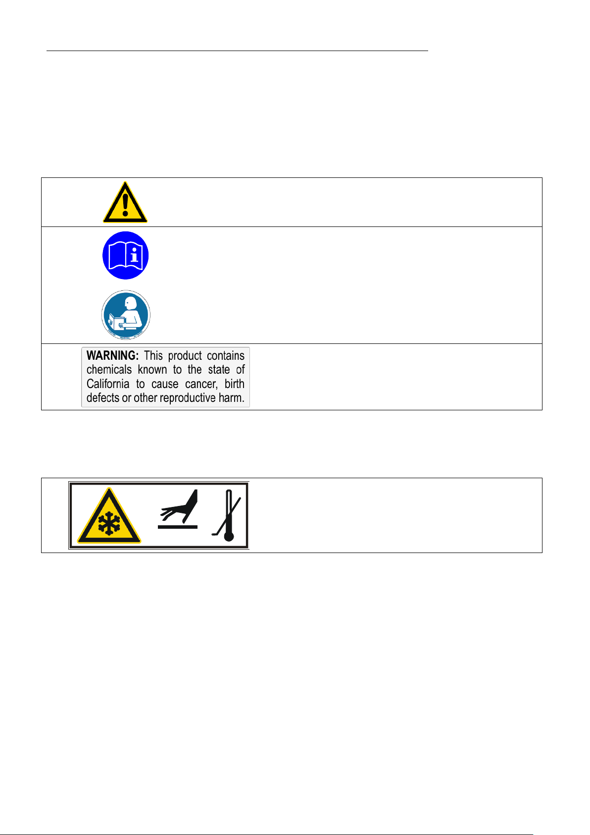
Warning label Proposition 65
Particular care and attention is necessary because of the wide operating range.
There are thermal dangers: Touchable parts of the probe can be very cold.
The user must attach the enclosed safety labels to the unit so they are well visible.
Safety label including warning label W017: Colors:
yellow, black
Attention: Do not touch cold probe.
2.1. Disposal
The product may be used with oil as bath fluid. These oils fully or partially consist of mineral
oil or synthetic oil. For disposal, follow the instructions in the material safety data sheets.
This unit contains the refrigerants R134a R404A, and R-23, which at this time are not
considered harmful to the ozone layer. However, over the long operating period of the unit,
disposal rules may change. Therefore, only qualified personnel should handle the disposal.
6
Page 7

FT200
FD200
Temperature range
°C
-20 … +30
10 … 30
Cooling capacity
(medium ethanol)
°C
kW
+20 0 -30
0.25 0.15 0.04
+20 +10
0.22 0.18
Refrigerant
R134a
R134a
Recommanded flow rate
l/min
-----
2 - 3
Freezing protection
°C
-----
10
Immerson probe (Lxdia.)
cm
9x4
-----
Connection tubing (L)
cm
120
-----
Dimensions (WxLxH)
cm
18x27x39
18x27x39
Weight
kg
18
16
Ambient temperature
°C
5 ... 35
5 ... 35
Mains power connection
V/Hz
190-253 /50
230/50
Current draw (at 230 V)
A
2.0
2.0
Mains power connection
V/Hz
103-127 / 60
115 / 60
Current draw (at 115 V)
A
3.0
3.0
FT400
FT900
Temperature range
°C
-40 ... +30
-90 ... +30
Cooling capacity
(medium ethanol)
°C
kW
+20 +10 -20 -40
0.45 0.36 0.14 0.03
+20 +10 -40 -80
0.3 0.27 0.2 0.07
Cooling compressor
1-stage
2-stage
Refrigerant
R404A
R404A/R23
Immerson probe (Lxdia.)
cm
12x5
65x1.5 (flexible)
Connection tubing (L)
cm
120
160
Dimensions (WxLxH)
cm
20x30x43
38x55x60
Weight
kg
24
50
Ambient temperature
°C
5 ... 35
5 ... 35
Mains power connection
V/Hz
230 /50
230 / 50/60
Current draw (at 230 V)
A
3.0
6.0
Mains power connection
V/Hz
115 / 60
115 / 60
Current draw (at 115 V)
A
4.0
7.0
2.2. Technical specifications
Note:
All measurements have been carried out at:
rated voltage and frequency; ambient temperature 20 °C.
7
Page 8

Operator responsibility – Safety instructions
Caution:
Environmental conditions according to IEC 61 010-1:
Use indoors only.
Altitude up to 2000 m - normal zero.
Ambient temperature: see Technical specifications
Humidity:
Max. relative humidity 80% for temperatures up to +31 °C,
linear decrease down to 50% relative humidity at a temperature of +40 °C
Max. mains voltage fluctuations of ±10% are permissible.
Protection class according to IEC 60 529 IP21
The unit corresponds to Class I
Overvoltage category II
Pollution degree 2
The unit is not for use in explosive environment.
EMC requirements according to EN 61326-1
This unit is an ISM device classified in Group 1 (using high frequency for internal purposes),
Class A (industrial and commercial range).
8
Page 9

FT400 FT200
FT 400
1
3
2
FT 400
1
3
2
10
A
M
P
10
A
M
P
12
11
FD 200
1
9
10
Operating instructions
3. OPERATING CONTROLS AND FUNCTIONAL ELEMENTS
Rear view
1 Mains switch, illuminated
2 Cooling control light
3 Clamp for immersion probe
7 Removable ventilation grid
8 Castor with locking lever
9 Tube connection - discharge
10 Tube connection - intake
11 Mains power cable with plug
12 Safety cutouts: Mains fuses 10 A
FD200
9
Page 10

OPERATING CONTRO LS AND FUNCTIONAL ELEMENTS
FT900
FT900
123
7
8
Rear view
11
10
Page 11

In addition to the safety warnings listed above, warnings are posted
Warning:
Caution:
Notice:
anything in its surroundings can be damaged.
Note!
Important!
Indicates usage tips and other useful information.
Follow the safety instructions to avoid personal injury and property damage. Also,
• Do not bend the tube connection of the immersion probe
4. Safety notes for the user
4.1. Explanation of safety notes
throughout the manual. These warnings are designated by an exclamation
mark inside an equilateral triangle. “Warning of a dangerous situation
(Attention! Please follow the documentation).”
The danger is classified using a signal word.
Read and follow these important instructions.
Describes a possibly highly dangerous situation. If these instructions are not
followed, serious injury and danger to life could result.
Describes a possibly dangerous situation. If this is not avoided, slight or minor
injuries could result. A warning of possible property damage may also be
contained in the text.
Describes a possibly harmful situation. If this is not avoided, the product or
4.2. Explanation of other notes
Draws attention to something special.
4.3. Safety instructions
the valid safety instructions for workplaces must be followed.
• Only connect the unit to a power socket with an earthing contact (PE –
protective earth)!
• The power supply plug serves as a safe disconnecting device from the
line and must always be easily accessible.
• Place the unit on an even surface on a base made of nonflammable
material.
• Do not stay in the area below the unit.
• Make sure you read and understand all instructions and safety
precautions listed in this manual before installing or operating your unit.
• Do not touch the immersion probe if it is frosted.
11
Page 12

Safety notes for the user
Use gloves.
cancer, birth defects or other reproductive harm.
• Keep the air intake and exhaust grids free of obstructions. (Maintain a
sufficient distance from all surrounding surfaces!)
• Do not move the unit from the position where it was set up during
operation.
• Always turn off the unit and disconnect the mains cable from the power
source before performing any service or maintenance procedures, or
before moving the unit.
• Always turn off the unit and disconnect the mains cable from the power
source before cleaning the unit.
• Transport the unit with care.
• Sudden jolts or drops may cause damage in the interior of the unit.
• Observe all warning labels.
• Never remove warning labels.
• Never operate units with damaged mains power cables.
• Repairs are to be carried out only by qualified service personnel.
• There are thermal dangers: Touchable parts of the probe can be very
cold. Therefore, exercise particular caution when touching these parts.
WARNING
This product contains chemicals known to the state of California to cause
12
Page 13

5. Preparations
Avoid touching the immersion probe if it is frosted.
Switch the unit on only if the probe is immersed into the bath fluid.
5.1. Installation
• Place the unit on an even surface on a pad made of non-
• Press down the castor levers on model FT900.
• The instrument should be set up at a frost-proof and dry location.
• The place of installation should be large enough and provide
• The ambient temperature must not exceed 35 °C.
flammable material.
sufficient air ventilation to ensure the room does not warm up
excessively because of the heat the instrument rejects to the
environment. (Max. permissible ambient temperature: 35 °C).
For a fault (leakage) in the refrigeration system, the standard EN
378 prescribes a certain room space to be available for each kg of
refrigerant.
> For 0.25 kg of refrigerant R134a, 1 m3 of space is required.
> For 0.52 kg of refrigerant R404A, 1 m3 of space is required.
> For 0.68 kg of refrigerant R23, 1 m3 of space is required.
• Keep at least 20 cm of open space on the front and rear venting
grids.
• Do not set up the unit in the immediate vicinity of heat sources and
do not expose to sun light.
• Before operating the unit after transport, wait about one hour after
setting it up. This will allow any oil that has accumulated laterally
during transport to flow back down thus ensuring maximum cooling
performance of the compressor.
5.2. Immersion Probe
DANGER OF INJURY. Use gloves.
To prevent the immersion probe (A) from icing, it should be completely
immersed into the bath liquid (B).
13
Page 14

OPERATING PROCEDURE S
Caution:
• We disclaim all liability for damage caused by incorrect line voltages!
Deviations of ±10 % are permissible.
• The immersion cooler is turned on and off with the mains switch.
The immersion probe – as part of the cooling circuit – should not be exposed
DANGER OF INJURY!
Accessory: Clamp for cooler probe FT200/400 - order no. 8 970 400
5.3. Tube connection FD200
• Connect the tubes and secure with tube clamps.
discharge (9)
intake (10)
Recommended flow rate: 2 to 3 l/min
6. OPERATING PROCEDURES
6.1. Power connection
• Only connect the unit to a power socket with earthing contact (PE –
Make sure that the line voltage and frequency match the supply
protective earth)!
• The power supply plug serves as safe disconnecting device from the line
and must be always easily accessible.
• Never operate equipment with damaged mains power cables.
• Regularly check the mains power cables for material defects (e.g. for
cracks).
voltage specified on the type plate.
6.2. Switching On
(1).
The control light in the switch will illuminate.
to bath temperatures above the working temperature of the immersion cooler.
This would cause damage to the compressor.
Do not immerse a frosted immersion probe into hot bath oil.
14
Page 15

7. TROUBLESHOOTING
• Malfunction of compressor:
Caution:
Prevent humidity from entering into the immersion cooler.
FT 400
The cooling compressor is equipped with an overload
protection device that will be triggered by overheating or
excessive current consumption. Possible causes include
insufficient ventilation or contamination of the condenser.
After a cool-down phase, the motor is automatically
switched on again.
• Interruption of the cooling loop (FD200) by a bended
tube.
8. Cleaning / repairing the unit
Before cleaning the unit, disconnect the power plug from the mains socket!
Always turn off the unit and disconnect the mains cable from the power source
before performing any service or maintenance procedures.
Service and repair work may be performed only by authorized electricians.
JULABO coolers are designed for continuous operation under
normal conditions.
Periodic maintenance is not required.
Regularly check the condensor for dirt contamination. Clean
the ribbed condensor, because dust and dirt will reduce
cooling performance of the unit.
Cleaning the Cooling Compressor:
• Switch off the unit, disconnect mains power cable.
Remove the hood (FD200, FT200, FT400).
15
Page 16

Cleaning / repairing the unit
FT900
from insufficient packing.
• The ventilation grid (7) is detached by unscrewing the four
mouting screws (FT900).
• Clean the ribbed condensor with a vacuum cleaner.
• Replace the hood or the ventilation grid.
• Switch on the unit.
Clean the outside of the unit using a wet cloth and low surface
tension water.
Repairs
Before asking for a service technician or returning a JULABO
instrument for repair, please contact an authorized JULABO
service station.
When returning the unit:
• Clean the unit in order to avoid any harm to the service
personnel.
• Attach a short fault description.
• During transport the unit has to stand upright. Mark the
packing correspondingly.
• When returning a unit, take care of careful and adequate
packing.
• JULABO is not responsible for damages that might occur
16
Page 17

9. WARRANTY PROVISIONS
The following Warranty Provisions shall apply to products sold in North America by Julabo (“Seller”) to the entity
shown as buyer (“Buyer”) on Seller’s invoice.
1. Initial Warranty. Upon Seller’s receipt of payment in full for the products and subject to
Buyer’s compliance with the terms of sale and any other agreement with Seller relating to the products, Seller
warrants to the Buyer that the products manufactured by the Seller are free from defects in material and
workmanship for a period not to exceed two (2) years or ten thousand (10,000) hours of operation, whichever
comes first, from the date the product is shipped by Seller to Buyer (the “Initial Warranty”).
2. EXCLUSION OF ALL OTHER EXPRESS WARRANTIES; EXCLUSION OF ALL IMPLIED
WARRANTIES. OTHER THAN THE INITIAL WARRANTY, NO OTHER EXPRESS WARRANTIES ARE MADE.
ALL IMPLIED WARRANTIES OF EVERY TYPE AND KIND, INCLUDING BUT NOT LIMITED TO ANY
IMPLIED WARRANTY OF MERCHANTABILITY OR FITNESS FOR A PARTICULAR PURPOSE OR USE,
ARE EXCLUDED IN ALL RESPECTS AND FO R ALL PURPOSES. SELLER DISCLAIMS AND MAKES NO
IMPLIED WARRANTIES WHATSOEVER.
3. Exclusions. The Initial Warranty does not include damage to the product resulting from
accident, misuse, improper installation or operation, unauthorized or improper repair, replacement or alteration
(including but not limited to repairs, replacements, or alterations made or performed by persons other than
Seller’s employees or authorized representatives), failure to provide or use of improper maintenance,
unreasonable use or abuse of the product, or failure to follow written installation or operating instructions. Buyer
must return the product’s record of purchase to the Seller or one of Seller’s authorized representatives within
thirty (30) days of the date the product is shipped by Seller to Buyer in order to make a claim under the Initial
Warranty. Notwithstanding anything contained herein to the contrary, all glassware, including but not limited to
reference thermometers, are expressly excluded from the Initial Warranty.
4. Buyer’s sole remedies; Limitations on Seller’s Liability. Buyer’s sole and exclusive
remedy under the Initial Warranty is strictly limited, in Seller’s sole discretion, to either: (i) repairing defective
parts; or (ii) replacing defective parts. In either case, the warranty period for the product receiving a repaired or
replaced part pursuant to the terms of the Initial Warranty shall not be extended. All repairs or replacements
performed by Seller pursuant to these Warranty Provisions shall be performed at Seller’s facility in Allentown,
Pennsylvania, U.S.A. or at the facility of an authorized representative of Seller, which location shall be
determined by Seller in its sole discretion; provided, however, that Seller may, in its sole discretion perform such
repairs or replacements at Buyer’s facility in which case Buyer shall pay Seller’s travel, living and related
expenses incurred by Seller in performing the repairs or replacements at Buyer’s facility. As a condition
precedent to Seller’s obligation to repair or replace a product part under the Initial Warranty, Buyer shall (i)
promptly notify Seller in writing of any such defect; (ii) shall have returned the product’s record of purchase to
Seller or to one of Seller’s authorized representatives within thirty (30) days of the date the product is delivered
to Buyer; and (iii) assist Seller in all respects in its attempts to determine the legitimacy and basis of any claims
made by or on behalf of Buyer including but not limited to providing Seller with access to the product to check
operating conditions. If Buyer does not provide such written notice to Seller within the Initial Warranty period or
fails to return the product’s record of purchase as set forth above, Seller shall have no further liability or
obligation to Buyer therefore. In no event shall Seller’s liability under the Initial Warranty exceed the original
purchase price of the product which is the subject of the alleged defect.
5. THE REMEDIES PROVIDED IN THE INITIAL WARRANTY ARE THE SOLE AND
EXCLUSIVE REMEDIES AVAILABLE TO THE BUYER. NOTWITHSTANDING ANYTHING TO THE
CONTRARY CONTAINED HEREIN, AND EVE N IF THE SOLE AND EXCLUS IVE REMEDIES FAI L OF THEIR
17
Page 18

WARRANTY PROVISIONS
ESSENTIAL PURPOSE FOR ANY REASON WHATSOEVER, IN NO EVENT SHALL SELLER BE LIABLE
FOR BUYER’S MANUFACTURING COSTS, LOST PROFITS, GOODWILL, OR ANY OTHER SPECIAL,
INDIRECT, PUNITIVE, INCIDENTAL OR CONSE QUENTIAL DAMAGES TO BUYER OR ANY THIRD PARTY
AND ALL SUCH DAMAGES ARE HEREBY DISCLAIMED.
6. Assignment. Buyer shall not assign any of its rights or obligations hereunder without the prior
written approval of Seller; provided, however, that if Buyer is a distributor of Seller, the rights and obligations of
Buyer under these Warranty Provisions shall inure to the benefit of and be binding upon Buyer’s customers who
provide the product’s proof of purchase to Seller pursuant to the terms set forth herein. Seller may assign any or all
of its rights or obligati ons hereunder w i thout Buy er ’ s pr i or cons ent.
7. Governing Law. The Warranty Provisions and all questions relating to their validity,
interpretation, performance, and enforcement shall be construed in accordance with, and shall be governed by, the
substantive laws of the Comm onw eal th of Penns yl v ania w i thout r egar d to i ts pr i nci pl es of c onfl i cts of l aw .
8. Waiver. Any failure of the part of Seller to insist on strict compliance with the Warranty Provisions
shall no way constitute a waiver of such right. No claim or rights arising out of a breach of the Warranty Provisions
by Buyer may be discharged in whole or in part by a waiver of the claim or right, unless the waiver is in writing signed
by an authorized representative of Seller. Seller’s waiver or acceptance of any breach by Buyer of any provisions of
the Warranty Provisions shall not constitute a waiver of or an excuse for nonper for m anc e as to any other pr ovi s ion of
the Warranty Provisions nor as to any prior or subs equent br each of the sam e pr ov is i on.
9. Freight. Buyer will arrange and pay for shipping and handling charges for the unit to be returned to
the Seller.Seller will arrange and pay for shi pping and handl i ng for the r etur n of the uni t to the Buy er .
18
Page 19

19
Page 20

WARRANTY PROVISIONS
20
 Loading...