


English
Operating manual
FT902
°C
www.julabo.com
Immersion Coolers
FT402
FT902
FT903
19534620-V4.doc Printing: 03.02.17
JULABO USA, Inc.
884 Marcon Boulevard
Allentown, PA 18109
Phone: +1(610) 231-0250
Fax: +1(610) 231-0260
info.us@julabo.com

Temperature control devices for research and industry are developed,
9001
Congratulations!
You have made an excellent choice.
JULABO thanks you for the trust you have placed in us.
This operating manual has been designed to help you gain an understanding of the operation
and possible applications of our immersion coolers. For optimal utilization of all functions, we
recommend that you thoroughly study this manual prior to beginning operation.
The JULABO Quality Management System
produced, and distributed according to the requirements of ISO
and ISO 14001. Certificate Registration No. 01 100044846
Unpacking and inspecting
Unpack the immersion cooler and accessories and inspect them for possible transport
damage. Damage should be reported to the responsible carrier, railway, or postal authority,
and a damage report should be requested. These instructions must be followed fully for us to
guarantee our full support of your claim for protecting against loss from concealed damage.
The form required for filing such a claim will be provided by the carrier.
1.953.4620-V4 02/17 Printed in Germany Changes without prior notification reserved
Important: keep operating manual for future use
2

Immersion Coolers
TABLE OF CONTENTS
Operating manual .................................................................................................................... 4
1. Intended use ................................................................................................................... 4
1.1. Description .................................................................................................................. 4
2. Operator responsibility – Safety instructions ................................................................... 4
2.1. Disposal ...................................................................................................................... 7
2.2. Technical specifications .............................................................................................. 8
Operating instructions ........................................................................................................... 11
3. Operating controls and functional elements .................................................................. 11
4. Safety notes for the user ............................................................................................... 13
4.1. Explanation of safety notes ....................................................................................... 13
4.2. Explanation of other notes ........................................................................................ 13
4.3. Safety instructions .................................................................................................... 14
5. Preparations .................................................................................................................. 15
5.1. Installation ................................................................................................................. 15
5.2. Immersion probe / Sensor connection - Pt100 .......................................................... 16
6. Operating procedures ................................................................................................... 17
6.1. Power connection ..................................................................................................... 17
6.2. Switching on / Start - Stop ........................................................................................ 17
6.3. Automatic / non-automatic start mode ...................................................................... 18
6.4. Setting the temperatures........................................................................................... 19
6.5. Temperature control.................................................................................................. 19
7. Troubleshooting guide / Error messages ...................................................................... 20
8. Electrical connection ..................................................................................................... 21
9. Cleaning / repairing the unit .......................................................................................... 22
10. WARRANTY PROVISIONS .......................................................................................... 24
3
Operating manual
JULABO immersion coolers are not suitable for direct temperature control of
medium (bath fluid).
PID1
Pt100
IEC
EN
DIN
Operating manual
1. Intended use
JULABO immersion coolers have been designed for temperature application to specific fluids
in a bath tank.
For example: Dewar vessels, beakers, or other containers in conjunction
with heating circulators for continuous countercooling
or for dry-ice substitution.
foods, semi-luxury foods and tobacco, or pharmaceutical and medical products.
Direct temperature control means unprotected contact of the object with the bath
1.1. Description
The immersion coolers are operated via the keypad. The implemented
microprocessor technology allows to set and to store the setpoint that can
be indicated on the LED temperature display.
The PID temperature control adapts the cooling supply to the thermal
requirements of the bath.
Electrical connection:
Connection for Pt100 external sensor for temperature measurement and
control.
Model FT402 is provided with a handle for portable use.
The Models FT902, FT903 are equipped with four castors. Two of the
castors include locking levers that should be pressed down after setting up
the unit to prevent it from moving.
The immersion probe is connected to the instrument with a flexible, specially
insulated tube. On models FT902, FT903 the immersion probe is also
flexible and may be adjusted precisely to different positions within the vessel.
2. Operator responsibility – Safety instructions
The products of JULABO ensure safe operation when installed, operated, and maintained
according to common safety regulations. This section explains the potential dangers that may
arise when operating the circulator and also specifies the most important safety precautions to
preclude these dangers as far as possible.
The operator is responsible for the qualification of the personnel operating the units.
The personnel operating the units should be regularly instructed about the dangers
involved with their job activities as well as measures to avert these dangers.
4

Immersion Coolers
Make sure all persons tasked with operating, installing, and maintaining the unit have read
and understand the safety information and operating instructions.
When using hazardous materials or materials that could become hazardous, the circulator
may be operated only by persons who are absolutely familiar with these materials and the
circulator. These persons must be fully aware of possible risks.
If you have any questions concerning the operation of your unit or the information in this
manual, please contact us!
Contact JULABO USA, Inc.
884 Marcon Boulevard
Allentown, PA 18109
Safety instructions for the operator:
Avoid strikes to the housing, vibrations, damage to the operating-element panel (keypad,
display), and contamination.
Make sure the product is checked for proper condition regularly (depending on the
conditions of use). Regularly check (at least every 2 years) the proper condition of the
mandatory, warning, prohibition and safety labels.
Make sure that the mains power supply has low impedance to avoid any negative effects
on the instruments being operated on the same mains.
This unit is designed for operation in a controlled electromagnetic environment. This
means that transmitting devices (e.g., cellular phones) should not be used in the
immediate vicinity.
Magnetic radiation may affect other devices with components sensitive to magnetic fields
(e.g., monitors). We recommend maintaining a minimum distance of 1 m.
Phone: +1(610) 231-0250
Fax: +1(610) 231-0260
info.us@ julabo.com
www.julabo.com
Permissible ambient temperature: max. 35 °C, min. 5 °C.
Permissible relative humidity: 50% (35 °C).
Do not store the unit in an aggressive atmosphere. Protect the unit from contamination.
Do not expose the unit to sunlight.
Appropriate operation
Only qualified personnel is authorized to configure, install, maintain, or repair the circulator.
Persons who operate the circulator must be trained in the particular tasks by qualified
personnel. The summarized user guidance (short manual) and the specification table with
information on individual parameters are sufficient for this.
5
Operator responsibility – Safety instructions
Use
The bath can be filled with flammable materials. Fire hazard!
There might be chemical dangers depending on the bath medium used.
Observe all warnings for the used materials (bath fluids) and the respective instructions (safety
data sheets).
Insufficient ventilation may result in the formation of explosive mixtures. Only use the unit in
well ventilated areas.
Only use recommended materials (bath fluids). Only use non-acid and non corroding
materials.
When using hazardous materials or materials that could become hazardous, the operator
must affix the enclosed safety labels to the front of the unit so they are highly visible:
If this unit is intended for use within the United States of America, all 3 warning labels must be
affixed to the housing of the unit prior to use. Directions for the positioning of the individual
warning labels are enclosed with the warning labels included in the delivery. Warning labels
must be easily visible to users.
1
2
or
2
3
Particular care and attention is necessary because of the wide operating range.
There are thermal dangers: Touchable parts of the probe can be very cold.
The user must attach the enclosed safety labels to the unit so they are easily visible.
Danger area. Attention! Observe instructions.
(operating manual, safety data sheet)
Carefully read the user information prior to beginning operation.
Scope: EU
Carefully read the user information prior to beginning operation.
Scope: USA, NAFTA
Warning label Proposition 65
6
Attention:
- Note a minimum bending radius of the probe.
- Do not touch cold probe.

Immersion Coolers
2.1. Disposal
The product may be used with oil as bath fluid. These oils fully or partially consist of mineral
oil or synthetic oil. For disposal, follow the instructions in the material safety data sheets.
This unit contains the refrigerants R134a R-404A, and R-23, which at this time are not
considered harmful to the ozone layer. However, over the long operating period of the unit,
disposal rules may change. Therefore, only qualified personnel should handle the disposal.
7

Operator responsibility – Safety instructions
2.2. Technical specifications
Immersion cooler FT402
Working temperature range °C -40 ... 30
Temperature stability °C ±0.5
Temperature selection digital
Temperature indication LED
Resolution °C 0.1
Temperature control PID1
Cooling capacity °C
Medium ethanol kW
Cooling compressor 1-stage
Refrigerant 230 V / 50 Hz
115 V / 60 Hz
Electrical connections:
Pt100 external sensor Pt100
Overall dimensions (WxDxH) cm 20x30x43
Immersion probe (Lxdia.) cm 12x5
Immersion probe, flexible (Lxdia.) cm -------
Connection tubing (L) cm 120
Noise level, distance 1 m dBA 61
Weight kg 24
Ambient temperature °C 5 ... 35
+20 10 -20 -40
0.45 0.36 0.14 0.03
R404A
R134a
Mains power connection V/ Hz 230 / 50- 60
Current input (at 230 V) A 4
Mains power connection V/ Hz 115 / 60
Current input (at 115 V) A 4
All measurements have been carried out at: rated voltage and frequency
ambient temperature: 20 °C Technical changes without prior notification reserved.
8

Immersion Coolers
Cooling capacity FT903
°C
20
10 0 -10
-20
-30
(Medium ethanol)
kW
0.3
0.29
0.27
0.26
0.25
0.24
(Medium ethanol)
kW
0.23
0.21
0.18
0.13
0.05
Cooling capacity FT902
Immersion cooler FT902 FT903
Working temperature range °C -90 ... 30
Temperature stability °C ±1
Temperature selection digital
Temperature indication LED
Resolution °C 0.1
Temperature control PID1
Cooling capacity FT903 °C -40 -50 -60 -70 -80
°C 20 10 -20 -40 -80
(Medium ethanol) kW 0.3 0.27 0.24 0.2 0.07
Cooling compressor 2-stage
Refrigerant 230 V / 50 Hz
115 V / 60 Hz
Electrical connections:
Pt100 external sensor Pt100
Overall dimensions (WxDxH) cm 38x55x60
Immersion probe (Lxdia.) cm ------- see dimensions page 18
Immersion probe, flexible
(Lxdia.)
Connection tubing (L) cm 160
Noise level, distance 1 m dBA 60
Weight kg 50 50
Ambient temperature °C 5 ... 35 5 ... 40
R404A/R23
R404A/R23
cm 65x1.5
Mains power connection
Current input
Mains power connection
Current input
All measurements have been carried out at: rated voltage and frequency
ambient temperature: 20 °C Technical changes without prior notification reserved.
V/ Hz 230 ±10 % / 50/60
A 6 6
V/ Hz 115 / 60 -
A 7 -
9

Operator responsibility – Safety instructions
Notice!
electromagnetic compatibility may be impacted.
Safety installations according to IEC 61010-2-010:
Alarm message optical + audible (permanent)
Environmental conditions according to IEC 61 010-1:
Use indoors only.
Altitude up to 2000 m - normal zero.
Ambient temperature: see Technical specifications
Humidity:
Max. relative humidity 80% for temperatures up to +31 °C,
linear decrease down to 50% relative humidity at a temperature of +40 °C
Max. mains voltage fluctuations of ±10% are permissible.
Protection class according to IEC 60 529 IP21
The unit corresponds to Class I
Overvoltage category II
Pollution degree 2
Caution:
The unit is not for use in explosive environment.
EMC requirements
The device is an ISM device of group 1 per CISPR 11 (uses HF for internal purposes) and is
classified in class A (industrial and commercial sector).
• Devices of class A are intended for the use in an industrial electromagnetic
environment.
• When operating in other electromagnetic environments, their
10

Operating instructions
1 - 7
8
9
10
FT 402
°C
11
12
13
10
AMP10AMP
off
3. Operating controls and functional elements
FT402 Front view Rear view
Immersion Coolers
1
2
3
4
5
6
7
Mains power switch, illuminated
I on
Edit keys (increase/decrease setting)
Enter key (store)
LED temperature display
Control indicator –Heating (without function)
Control indicator – Cooling
Control indicator – Alarm
11

Operating controls and functional elements
FT902
°C
1-7
8
9
10
15
14
16AMP16AM
P
11
12
13
15
15
A
M
P
FT902, FT903 Front view Rear view
8
Pt100
External Pt100 sensor connector
Included with each unit:
Order No. 8 981 003
Pt100 sensor, 200x6 mm dia., stainless steel
9 Clamp for immersion probe
10 Immersion probe
11 Mains power cable with plug
12
Mains circuit breakers (resettable)
FT402 10 A FT902, FT903 15 A
13 Carrying handle
14 Venting grid, removable (only FT902, FT903)
15 Castor with brake (at the front)
Castor without brake (at the back)
12

3.1. Dimensions of the FT903 probe
In addition to the safety warnings listed above, warnings are posted throughout
Caution:
Notice:
anything in its surroundings can be damaged.
Note!
Draws attention to something special.
Important!
Indicates usage tips and other useful information.
4. Safety notes for the user
4.1. Explanation of safety notes
Immersion Coolers
the manual. These warnings are designated by an exclamation mark inside an
equilateral triangle. “Warning of a dangerous situation (Attention! Please follow
the documentation).”
The danger is classified using a signal word.
Read and follow these important instructions.
Warning:
Describes a possibly highly dangerous situation. If these instructions are not
followed, serious injury and danger to life could result.
Describes a possibly dangerous situation. If this is not avoided, slight or minor
injuries could result. A warning of possible property damage may also be
contained in the text.
Describes a possibly harmful situation. If this is not avoided, the product or
4.2. Explanation of other notes
13

Safety notes for the user
Follow the safety instructions to avoid personal injury and property damage. Also,
gloves.
cancer, birth defects or other reproductive harm.
4.3. Safety instructions
the valid safety instructions for workplaces must be followed.
• Only connect the unit to a power socket with an earthing contact (PE –
protective earth)!
• The power supply plug serves as a safe disconnecting device from the line
and must always be easily accessible.
• Place the unit on an even surface on a base made of nonflammable
material.
• Do not stay in the area below the unit.
• Make sure you read and understand all instructions and safety precautions
listed in this manual before installing or operating your unit.
• Do not touch the immersion probe if it is frosted.
• Do not bend the tube connection of the immersion probe
• Keep the air intake and exhaust grids free of obstructions. (Maintain a
sufficient distance from all surrounding surfaces!)
• Do not move the unit from the position where it was set up during
operation.
• Always turn off the unit and disconnect the mains cable from the power
source before performing any service or maintenance procedures, or
before moving the unit.
• Always turn off the unit and disconnect the mains cable from the power
source before cleaning the unit.
• Transport the unit with care.
• Sudden jolts or drops may cause damage in the interior of the unit.
• Observe all warning labels.
• Never remove warning labels.
• Never operate units with damaged mains power cables.
• Repairs are to be carried out only by qualified service personnel.
• There are thermal dangers: Touchable parts of the probe can be very cold.
Therefore, exercise particular caution when touching these parts. Use
WARNING
This product contains chemicals known to the state of California to cause
14

performance of the compressor.
5. Preparations
5.1. Installation
• Place the unit on an even surface on a pad made of non-flammable
• Press down the castor levers on models FT902, FT903.
• The place of installation should be large enough and provide sufficient
Immersion Coolers
material.
air ventilation to ensure the room does not warm up excessively
because of the heat the instrument rejects to the environment. (Max.
permissible ambient temperature: 35 °C).
For a fault (leakage) in the refrigeration system, the standard EN 378
prescribes a certain room space to be available for each kg of
refrigerant.
> For 0.25 kg of refrigerant R134a, 1 m3 of space is required.
> For 0.52 kg of refrigerant R404A, 1 m3 of space is required.
> For 0.68 kg of refrigerant R23, 1 m3 of space is required.
• The instrument should be set up at a frost-proof and dry location.
• The ambient temperature must not exceed 35 °C.
• Keep at least 20 cm of open space on the front and rear venting grids.
• Do not set up the unit in the immediate vicinity of heat sources and do
not expose to sun light.
• Before operating the unit after transport, wait about one hour after
setting it up. This will allow any oil that has accumulated laterally
during transport to flow back down thus ensuring maximum cooling
15

Preparations
Caution:
Switch the unit on only if the probe is immersed into the bath fluid.
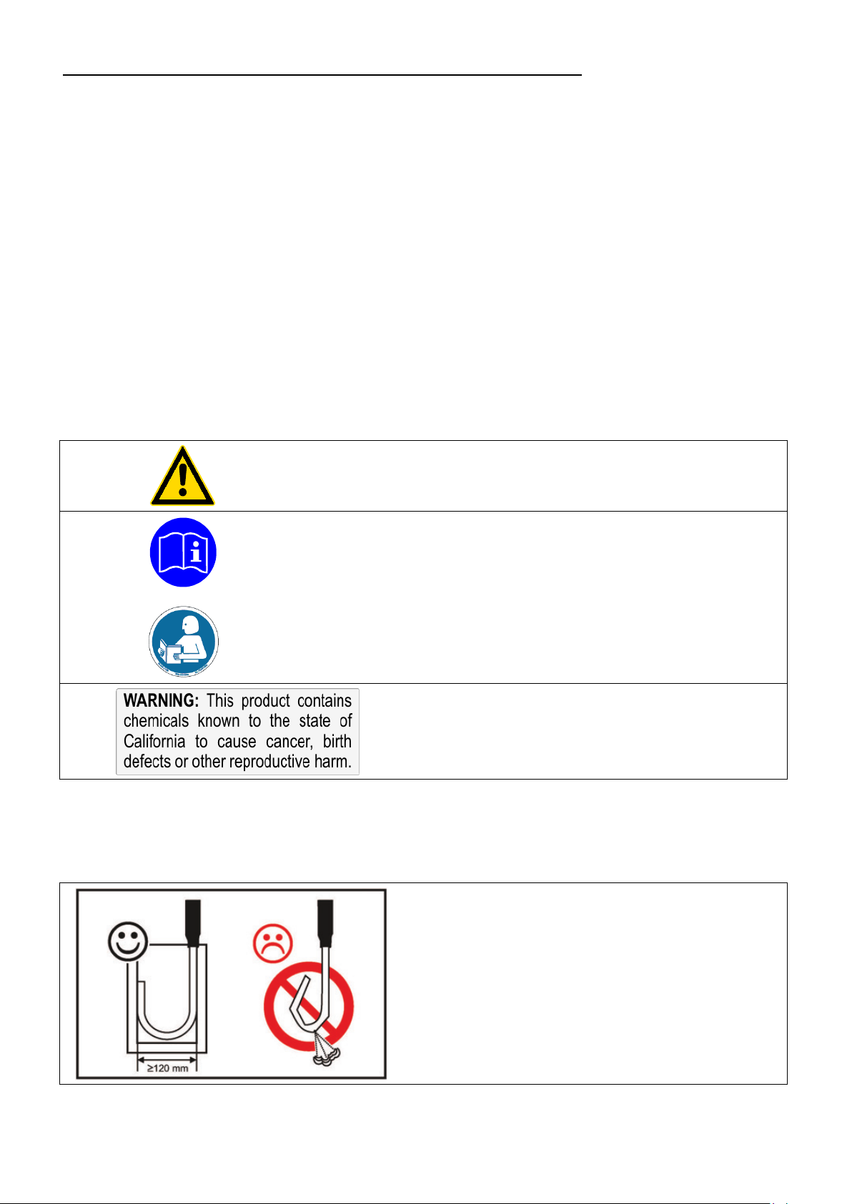
5.2. Immersion probe / Sensor connection - Pt100
Avoid touching the immersion probe if it is frosted.
DANGER OF INJURY. Use gloves.
The immersion coolers are provided with a Pt100 sensor 200x6 mm dia.,
Pt100
stainless steel - Order No. 8 981 003
• Connect the Pt100 sensor to the connector (Pt100) .
• To prevent the immersion probe (A) from icing, it should be completely
immersed into the bath liquid (B).
Important:
Place the external sensor (S) into the bath medium and securely fix the
sensor.
FT902: The diameter of the bent probe should not be less than
120 mm.
Accessories:
16
Order No. Description
8 981 005 Pt100 sensor 200x6 mm dia., glass, 1.5 m cable
8 981 010 Pt100 Fühler 300x6 mm dia., stainless steel, 1.5 m cable
8 970 400 Clamp for cooler probe FT402

6. Operating procedures
Caution:
Make sure that the line voltage and frequency match the supply voltage
Deviations of ±10 % are permissible.
• Switching on:
Turn the unit off with the mains power switch.
6.1. Power connection
• Only connect the unit to a power socket with earthing contact (PE – protective
earth)!
• The power supply plug serves as safe disconnecting device from the line and
must be always easily accessible.
• Never operate equipment with damaged mains power cables.
• Regularly check the mains power cables for material defects (e.g. for cracks).
We disclaim all liability for damage caused by incorrect line voltages!
specified on the type plate.
Immersion Coolers
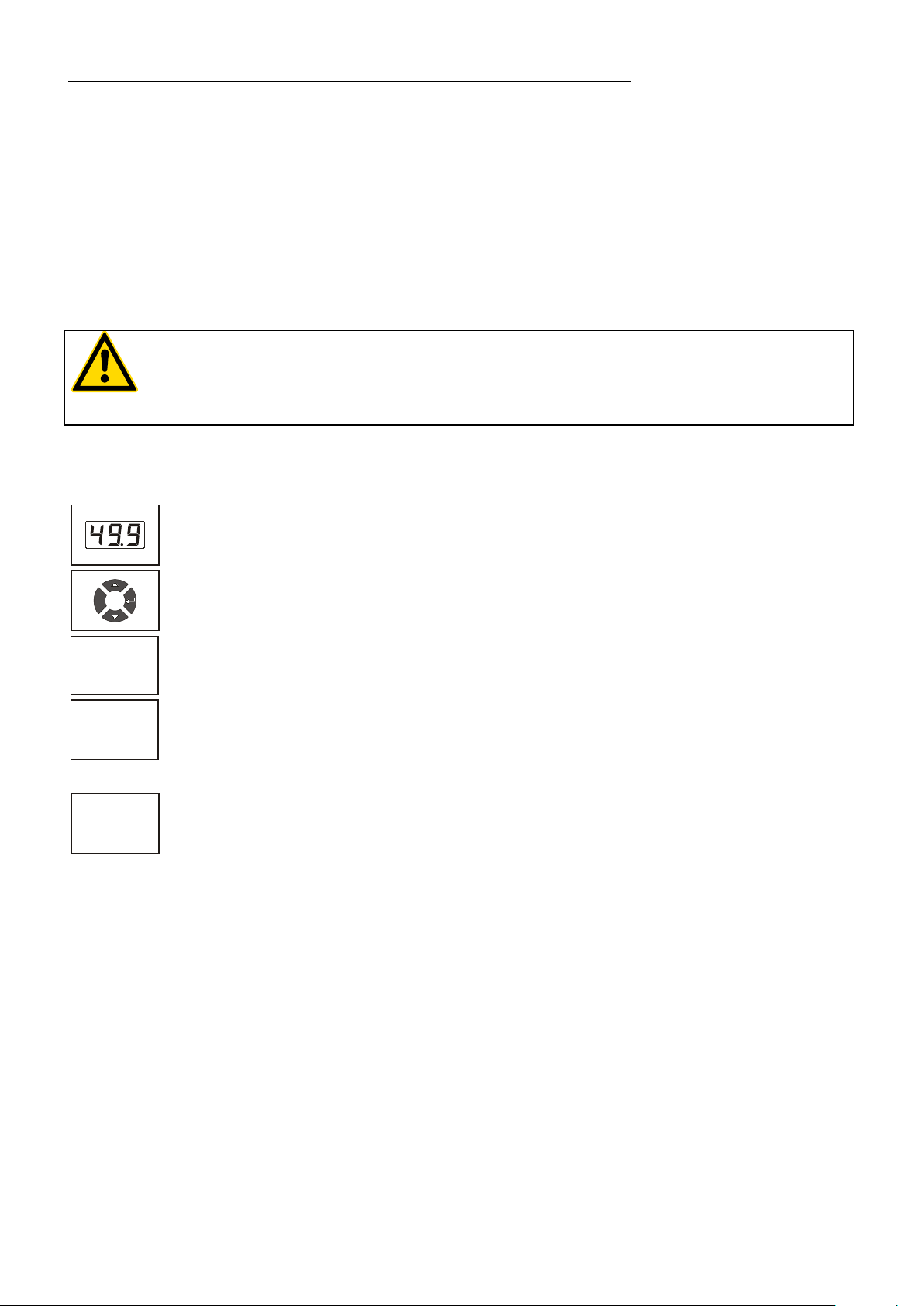
6.2. Switching on / Start - Stop
The immersion cooler is turned on and off with the mains switch. (1).
The unit performs a self-test. All segments of the 4-digit LED
temperature DISPLAY and all indicator lights will illuminate
(as illustrated on the left).
Then the software version (example: 11.0) appears.
The display "OFF" indicates the unit is ready to operate
(standby mode).
Start / Stop:
• Press enter for about 4 seconds.
Start: The LED temperature DISPLAY indicates the actual bath
temperature.
The cooling control indicator signals the cooling condition –
on/off.
Stop: The LED temperature DISPLAY indicates "OFF".
• Switching off:
17

Operating procedures
NOTE:
automatic start mode). This safe operating state is
remain stored, and the unit is
Warning:
For supervised or unsupervised operation with the AUTOSTART function, avoid
The instrument no longer conforms to N.A.M.U.R. recommendations.
6.3. Automatic / non-automatic start mode
Keep depressed enter and
turn on the immersion cooler with the mains power switch.
For a short while the LED temperature DISPLAY indicates the
effective start mode:
AUTOSTART on.
AUTOSTART off.
The immersion cooler has been configured and delivered by
JULABO according to N.A.M.U.R. recommendations. This means for
the start mode, that the unit must enter a safe operating state after a
power failure (nonindicated by „OFF“ on the LED temperature display. A complete
shutdown of the main functional elements is effected simultaneously.
The values set on the immersion cooler
returned to operation by pressing the start/stop key.
Should such a safety standard not be required, the AUTOSTART
function (automatic start mode) may be activated, thus allowing the
unit to be started directly by pressing the mains power switch or
using a timer.
any hazardous situation to persons or property.
18

1.
2.
3.
to the same bath
-10
0
°C
t
6.4. Setting the temperatures
Immersion Coolers
This function is used to set the lowest desired temperature value.
Setting can be carried out in the start/stop condition.
Press one of the keys for a short moment. The setpoint
value instead of the actual value is indicated on the display for
about 8 seconds. The value can now be changed.
Change value:
Press to set a higher value.
Press to set a lower value.
Keep the keys depressed for the value to change fast.
Press enter to store the value.
6.5. Temperature control
The immersion cooler can only control the temperature if both - the
Pt100 sensor and immersion probe - are immersed in
fluid.
Application: Cooling a fluid in a vessel
If the actual temperature falls below the setpoint temperature, the
compressor is switched off (on FT902, FT903: only one of the two
compressors).
The cooling control indicator goes out. If cooling is required
again, the compressor switches on automatically.
Example: Setpoint temperature –10 °C
19

Troubleshooting guide / Error messages
Response time and amplitude of the temperature curve are depending
Caution:
DANGER OF INJURY!
Whenever the microprocessor electronics registers a failure, a complete
of a code.
range.
15
A
M
P
The temperature curve resembles a two-point control (on-off).
on the volume of the bath fluid (amongst others).
According to manufacturer's instructions, there is an off-period of
minimum 4 minutes to protect the compressor.
The immersion probe – as part of the cooling circuit – should not be exposed to
bath temperatures above the working temperature of the immersion cooler.
This would cause damage to the compressor.
Do not immerse a frosted immersion probe into hot bath oil.
7. Troubleshooting guide / Error messages
+
shutdown of the compressor is performed.
The alarm light " " illuminates and a continuous signal tone sounds.
The LED temperature display indicates the cause for the alarm in form
Press enter
to quit the audible signal.
• Cable of the working temperature sensor interrupted or shortcircuited.
• The temperature inside the bath is outside the working temperature
After eliminating the malfunction, press the mains power switch off and
on again to cancel the alarm state.
If the unit cannot be returned to operation, contact an authorized
JULABO service station.
Mains circuit breakers (resettable)
FT402 10 A
FT902, FT903 15 A
20

housing.
4
1
3
2
1
4
2
3
Shield Plug
Look on
soldering side.
Pt100
8. Electrical connection
Notice:
Use shielded cables only.
The shield of the connecting cable is electrically connected to the plug
Connector for external Pt100 sensor
Pin assignment:
Pt100
Pin Signal
1 I+
2 U+
3 U 4 I-
The shield of the connecting cable is electrically connected to the
plug housing and the sensor tube.
Immersion Coolers
21

Cleaning / repairing the unit
Caution:
Prevent humidity from entering into the immersion cooler.
FT 4 02
°C
FT902
°C
The immersion cooler is designed for continuous operation
9. Cleaning / repairing the unit
Before cleaning the unit, disconnect the power plug from the mains socket!
Always turn off the unit and disconnect the mains cable from the power source
before performing any service or maintenance procedures.
Service and repair work may be performed only by authorized electricians.
under normal conditions.
Periodic maintenance is not required.
• Clean the outside of the unit using a wet cloth and low
surface tension water.
Regularly check the condensor for dirt contamination. Clean
the ribbed condensor, because dust and dirt will reduce
cooling performance of the unit.
Cleaning the Cooling Compressor:
• Switch off the unit, disconnect mains power cable.
• Model FT402: Remove the hood.
• Model FT902: The ventilation grid is detached by
unscrewing the four mouting screws
• Clean the ribbed condensor with a vacuum cleaner.
• Replace the hood or the ventilation grid.
• Switch on the unit.
22

Immersion Coolers
Before asking for a service technician or returning a JULABO
from insufficient packing.
JULABO reserves the right to carry out technical
performance of a unit.
Repairs
instrument for repair, please contact an authorized JULABO
service station.
When returning the unit:
• Clean the unit in order to avoid any harm to the service
personnel.
• Attach a short fault description.
• During transport the unit has to stand upright. Mark the
packing correspondingly.
• When returning a unit, take care of careful and adequate
packing.
• JULABO is not responsible for damages that might occur
modifications with repairs for providing improved
23

WARRANTY PROVISIONS
10. WARRANTY PROVISIONS
The following Warranty Provisions shall apply to products sold in North America by Julabo (“Seller”) to the entity
shown as buyer (“Buyer”) on Seller’s invoice.
1. Initial Warranty. Upon Seller’s receipt of payment in full for the products and subject to Buyer’s
compliance with the terms of sale and any other agreement with Seller relating to the products, Seller warrants to
the Buyer that the products manufactured by the Seller are free from defects in material and workmanship for a
period not to exceed two (2) years or ten thousand (10,000) hours of operation, whichever comes first, from the
date the product is shipped by Seller to Buyer (the “Initial Warranty”).
2. EXCLUSION OF ALL OTHER EXPRESS WARRANTIES; EXCLUSION OF ALL IMPLIED
WARRANTIES. OTHER THAN THE INITIAL WARRANTY, NO OTHER EXPRESS WARRANTIES ARE MADE.
ALL IMPLIED WARRANTIES OF EVERY TYPE AND KIND, INCLUDING BUT NOT LIMITED TO ANY IMPLIED
WARRANTY OF MERCHANTABILITY OR FITNESS FOR A PARTICULAR PURPOSE OR USE, ARE
EXCLUDED IN ALL RESPECTS AND FOR ALL PURPOSES. SELLER DISCLAIMS AND MAKES NO IMPLIED
WARRANTIES WHATSOEVER.
3. Exclusions. The Initial Warranty does not include damage to the product resulting from
accident, misuse, improper installation or operation, unauthorized or improper repair, replacement or alteration
(including but not limited to repairs, replacements, or alterations made or performed by persons other than Seller’s
employees or authorized representatives), failure to provide or use of improper maintenance, unreasonable use or
abuse of the product, or failure to follow written installation or operating instructions. Buyer must return the
product’s record of purchase to the Seller or one of Seller’s authorized representatives within thirty (30) days of the
date the product is shipped by Seller to Buyer in order to make a claim under the Initial Warranty. Notwithstanding
anything contained herein to the contrary, all glassware, including but not limited to reference thermometers, are
expressly excluded from the Initial Warranty.
4. Buyer’s sole remedies; Limitations on Seller’s Liability. Buyer’s sole and exclusive remedy
under the Initial Warranty is strictly limited, in Seller’s sole discretion, to either: (i) repairing defective parts; or (ii)
replacing defective parts. In either case, the warranty period for the product receiving a repaired or replaced part
pursuant to the terms of the Initial Warranty shall not be extended. All repairs or replacements performed by Seller
pursuant to these Warranty Provisions shall be performed at Seller’s facility in Allentown, Pennsylvania, U.S.A. at
the facility of an authorized representative of Seller, which location shall be determined by Seller in its sole
discretion; provided, however, that Seller may, in its sole discretion perform such repairs or replacements at
Buyer’s facility in which case Buyer shall pay Seller’s travel, living and related expenses incurred by Seller in
performing the repairs or replacements at Buyer’s facility. As a condition precedent to Seller’s obligation to repair
or replace a product part under the Initial Warranty, Buyer shall (i) promptly notify Seller in writing of any such
defect; (ii) shall have returned the product’s record of purchase to Seller or to one of Seller’s authorized
representatives within thirty (30) days of the date the product is delivered to Buyer; and (iii) assist Seller in all
respects in its attempts to determine the legitimacy and basis of any claims made by or on behalf of Buyer
including but not limited to providing Seller with access to the product to check operating conditions. If Buyer does
not provide such written notice to Seller within the Initial Warranty period or fails to return the product’s record of
purchase as set forth above, Seller shall have no further liability or obligation to Buyer therefore. In no event shall
Seller’s liability under the Initial Warranty exceed the original purchase price of the product which is the subject of
the alleged defect.
24

Immersion Coolers
5. THE REMEDIES PROVIDED IN THE INITIAL WARRANTY ARE THE SOLE AND EXCLUSIVE
REMEDIES AVAILABLE TO THE BUYER. NOTWITHSTANDING ANYTHING TO THE CONTRARY
CONTAINED HEREIN, AND EVEN IF THE SOLE AND EXCLUSIVE REMEDIES FAIL OF THEIR ESSENTIAL
PURPOSE FOR ANY REASON WHATSOEVER, IN NO EVENT SHALL SELLER BE LIABLE FOR BUYER’S
MANUFACTURING COSTS, LOST PROFITS, GOODWILL, OR ANY OTHER SPECIAL, INDIRECT, PUNITIVE,
INCIDENTAL OR CONSEQUENTIAL DAMAGES TO BUYER OR ANY THIRD PARTY AND ALL SUCH
DAMAGES ARE HEREBY DISCLAIMED.
6. Assignment. Buyer shall not assign any of its rights or obligations hereunder without the prior
written approval of Seller; provided, however, that if Buyer is a distributor of Seller, the rights and obligations of Buyer
under these Warranty Provisions shall inure to the benefit of and be binding upon Buyer’s customers who provide the
product’s proof of purchase to Seller pursuant to the terms set forth herein. Seller may assign any or all of its rights or
obligations hereunder without Buyer’s prior consent.
7. Governing Law. The Warranty Provisions and all questions relating to their validity, interpretation,
performance, and enforcement shall be construed in accordance with, and shall be governed by, the substantive laws
of the Commonwealth of Pennsylvania without regard to its principles of conflicts of law.
8. Waiver. Any failure of the part of Seller to insist on strict compliance with the Warranty Provisions
shall no way constitute a waiver of such right. No claim or rights arising out of a breach of the Warranty Provisions by
Buyer may be discharged in whole or in part by a waiver of the claim or right, unless the waiver is in writing signed by
an authorized representative of Seller. Seller’s waiver or acceptance of any breach by Buyer of any provisions of the
Warranty Provisions shall not constitute a waiver of or an excuse for nonperformance as to any other provision of the
Warranty Provisions nor as to any prior or subsequent breach of the same provision.
9. Freight. Buyer will arrange and pay for shipping and handling charges for the unit to be returned to
the Seller.Seller will arrange and pay for shipping and handling for the return of the unit to the Buyer.
25
 Loading...