

Page 1
English
www.julabo.de
Operating Manual
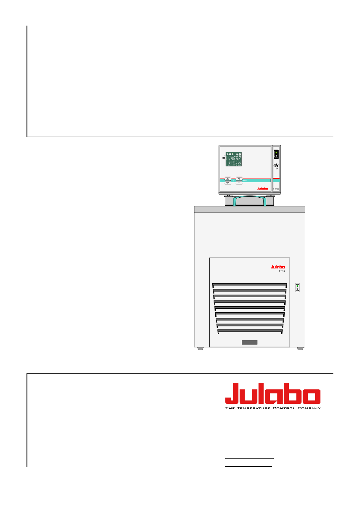
Refrigerated and
Heating Circulators
FP45-HE
1.951.2462-V2 09/14
JULABO GmbH
77960 Seelbach / Germany
Tel. +49 (0) 7823 / 51-0
Fax +49 (0) 7823 / 24 91
info@julabo.de
19512462-V2.doc 22.09.14
Page 2

Temperature control devices for research and industry are developed,
Congratulations!
You have made an excellent choice.
JULABO thanks you for the trust you have placed in us.
This operating manual has been designed to help you gain an understanding of the operation and
possibl e ap pl i cat ions of our ci r cul at or s . F or optimal utilization o f all funct ions, we rec ommend that you
thoroughly study this manual prior to beginning operation.
The JULABO Quality Management System
produced, and distributed according to the requirements of ISO 9001 and
ISO 14001. Certificate Registration No. 01 100044846
Unpacking and inspecting
Unpack the circulator and accessories and inspect them for possible transport damage. Damage
should be reported to the responsible carrier, railway, or postal authority, and a damage report should
be requested. These instructions must be followed fully for us to guarantee our full support of your
claim for pr ot ec ti n g against loss fr om c onc ealed dam ag e. T he for m req ui r ed for fil i n g suc h a clai m w i ll
be provided by the carrier.
Printed in Germany Changes without prior notification reserved
Important: keep operati ng manual for future use
2
Page 3

TABLE OF CONTENTS
Operating manual ................................................................................................................ 5
1. Intended use ................................................................................................................. 5
1.1. Description ............................................................................................................... 5
2. Operator responsibility – Safety recommendation s ....................................................... 6
2.1. Disposal ................................................................................................................... 8
2.2. Warranty con ditions ................................................................................................. 8
2.3. EC Conformity .......................................................................................................... 9
2.4. Technical specifications ......................................................................................... 11
Operating instructions ....................................................................................................... 13
3. Safety no tes for the user ............................................................................................. 13
3.1. Expl anation of safety notes .................................................................................... 13
3.2. Expl anation of other notes ...................................................................................... 13
HE
3.3. Safety recommendations ........................................................................................ 14
4. Operating controls and functional elements ................................................................ 16
5. Preparations ............................................................................................................... 19
5.1. Installation .............................................................................................................. 19
5.2. Bath fluids .............................................................................................................. 19
5.3. Temperature application to external systems ......................................................... 21
5.3.1. Tubing ............................................................................................................... 22
5.4. Filli ng / drai ning ...................................................................................................... 23
6. Operating procedures ................................................................................................. 24
6.1. Power connection ................................................................................................... 24
6.2. Switching on / Start - Stop ...................................................................................... 24
6.2.1. Switchin g on the circul ator .................................................................................
24
6.2.2. Switchin g on the Coolin g M ac hine ..................................................................... 25
7.
7.1. Using the pre-settings in the
Sett i ng of temperatures ................................................................................. 26
menu ........................................................... 26
7.2. Direct setting of temperatures ................................................................................ 27
8.
Safety installations, warning functions ........................................................... 28
8.1. Excess temperature protection ............................................................................... 28
8.1.1. Early warning system, low level protection ......................................................... 29
8.2. Switch-over from warning to shutdown function...................................................... 30
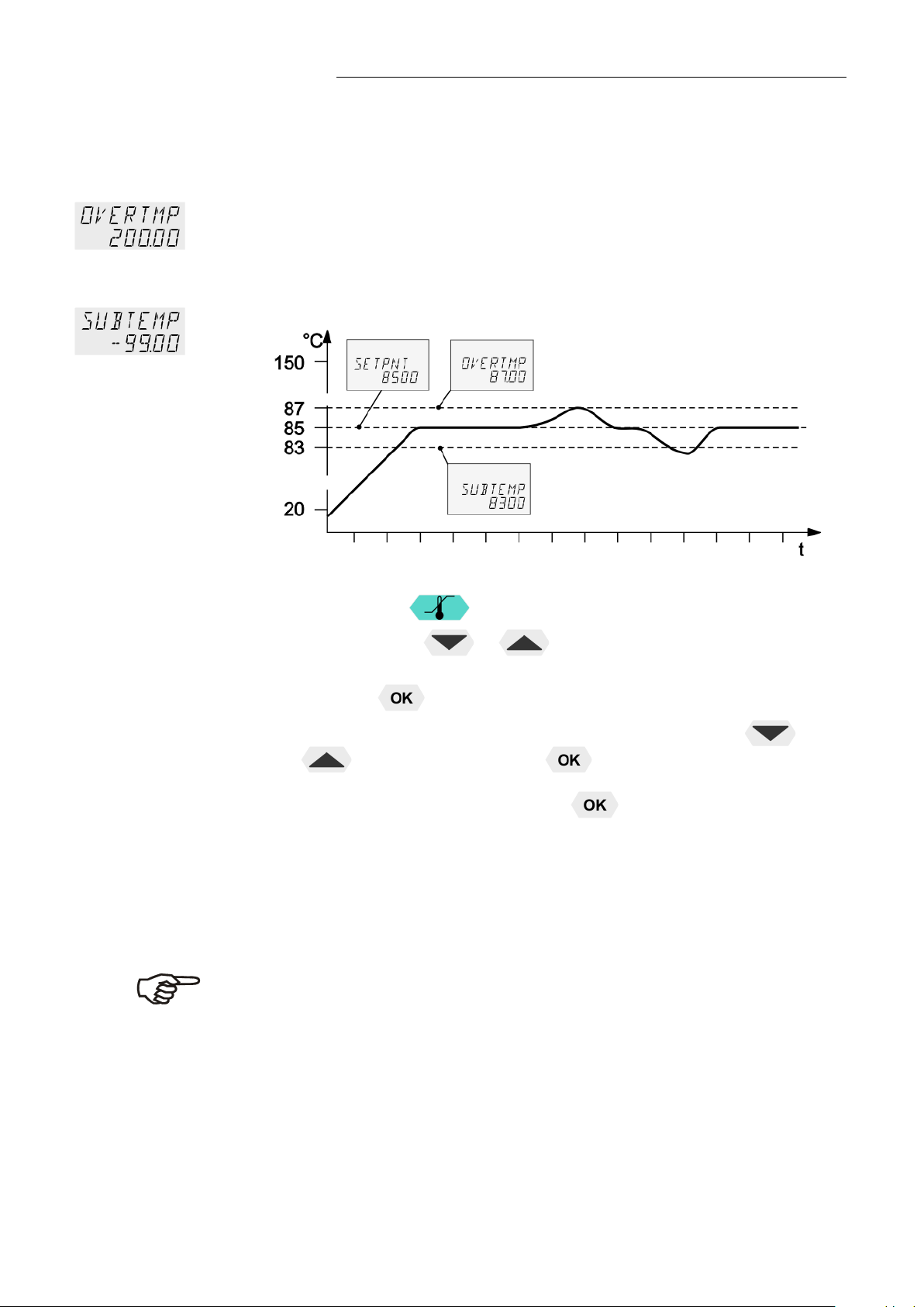
8.3. Over and Sub temperature warning function .......................................................... 31
9.
Menu func ti ons.............................................................................................. 32
9.1. MENU PROGRAM – START.................................................................................. 33
9.2. MENU PROGRAM – creatio n, adm i ni stration ......................................................... 36
3
Page 4

9.3. MENU PUMP - Setting of pump pressure ...............................................................38
9.4. MENU CONFIG - Configur at ion of unit ....................................................................39
9.4.1. Remote control via the serial interface ................................................................40
9.4.2. Keypad control or setpoint setting via the analog input .......................................41
9.4.3. AUTOSTART ......................................................................................................41
9.4.4. OFF-MODE ........................................................................................................42
9.4.5. ACTVAR - actuating variable ..............................................................................42
9.4.6. Setting of clock and date ....................................................................................43
9.4.7. RESET – Factory settings...................................................................................43
9.5. MENU CONTROL – Control char acteristics and parameters...................................43
9.5.1. CONTROL – Control INTERNAL / EXTERNAL ...................................................45
9.5.2. SELFTUNING .....................................................................................................46
9.5.3. Dynamic internal .................................................................................................46
9.5.4. Control parameters– XP-, TN-, TV- INTERNAL ..................................................47
9.5.5. COSPEED - external ..........................................................................................48
9.5.6. Control parameters – XPU-, XP-, TN-, TV- EXTERNAL ......................................48
9.6. MENU SERIAL - BAUDRATE, HANDSHAKE, PARITY ...........................................49
9.7. MENU ATC - Absolut Temperature Calibration .......................................................50
9.7.1. ATC SENSOR - INTERNAL / EXTERNAL ..........................................................52
9.7.2. ATC STATUS - YES / NO ...................................................................................52
9.7.3. CALIBRATION TYPE: 1 -/ 2 -/ 3 POINT..............................................................53
9.7.4. Example: 3-point calibration for internal control .................................................54
9.8. MENU LIMITS .........................................................................................................
56
9.8.1. Limits for internal control .....................................................................................57
9.8.2. Limits for external control ....................................................................................57
9.9. MENU IN/OUT – Analog inputs/outputs (Option) .....................................................59
9.9.1. Outputs of the connector - REG+E-PROG ..........................................................62
9.9.2. Input of the c on nector - REG+E-PROG ..............................................................63
9.9.3. ALARM-out put / Stand-by-input ..........................................................................65
10. Troubleshooting guide / error messages ......................................................................67
11. Electrical connections ..................................................................................................70
12. Remote control ............................................................................................................72
12.1. Setup for remote control ..........................................................................................72
12.2. Communication with a PC or a superordinated data system ...................................72
12.3. List of commands ....................................................................................................73
12.4. Status messages ....................................................................................................76
12.5. Error messages .......................................................................................................76
13. Installati o n o f elec tronic module ...................................................................................77
14. JULABO Service – Online remote diagnosis ................................................................78
15. Cleaning / re pair i n g t he unit .........................................................................................79
4
Page 5
HE
JULABO cir c ulators are not suita bl e for di r ect t emperature control o f fo ods, semi-
medium (bath fl ui d) .
1x10
TCF
ATC
3
RS232
Pt100
PUMP
SMART
temperature control parameters. This means full control of the control behavior at all
temperatures to ensure an accurate temperature pattern at the selected spot in the
Intelligent pump system: The pump capacity (electronically adjustable via the motor
Operating manual
1. Intended use
JULABO circulators have been designed to control the temperature of specific fluids in a bath tank.
The units f eat ur e pump connections for tempera t u r e cont r ol of external systems (loo p cir c ui t) .
luxury foo ds an d tobacco, or pharmac eu ti c al an d m edi cal pr o ducts.
Direct tem per ature control mea ns unprotected contact of the object wit h the bath
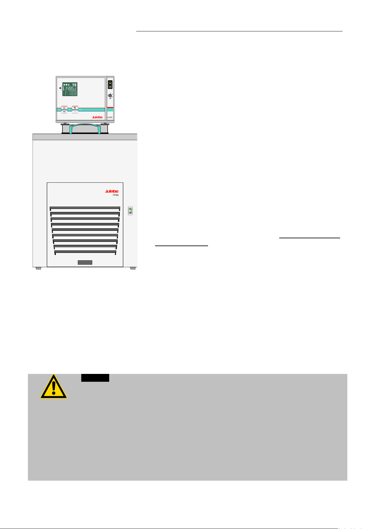
1.1. Description
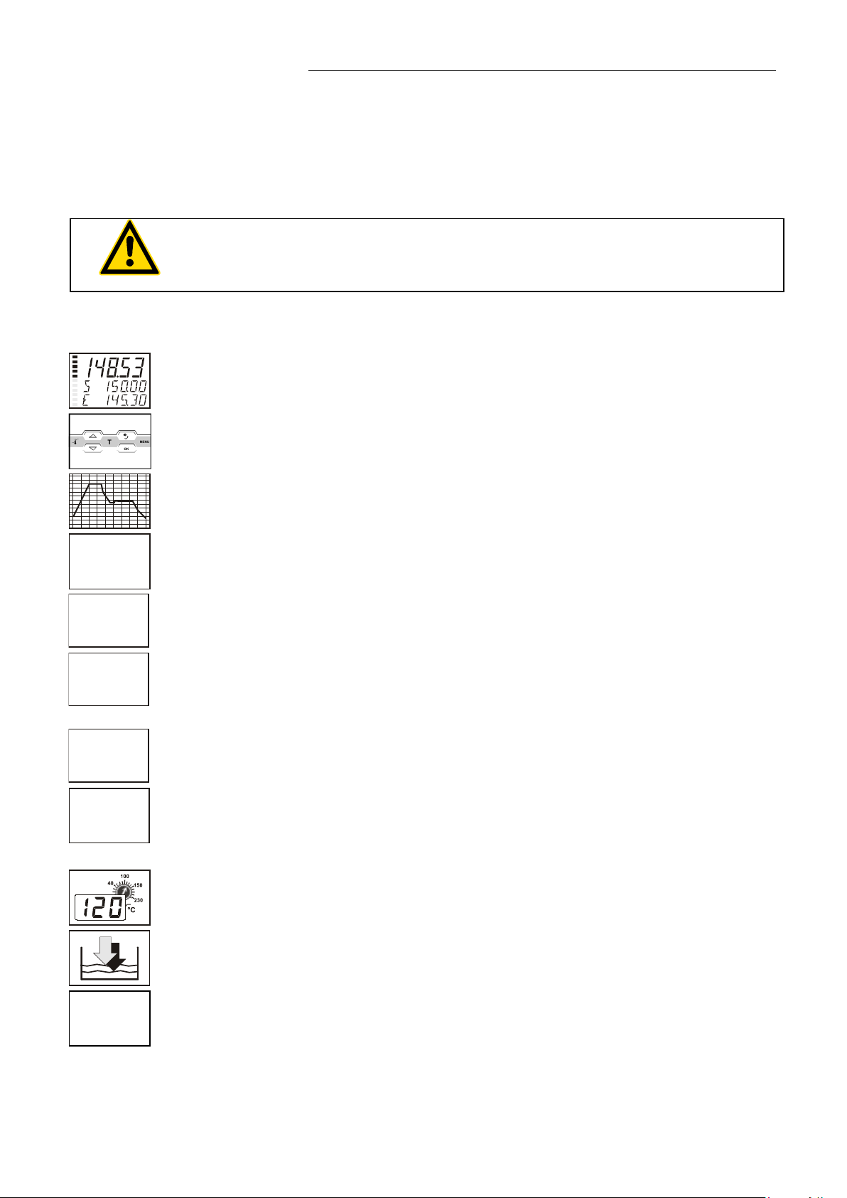
The circulators are operated via the splash-proof keypad. The implemented
microprocessor technology allows to set and to store different values that can be
indicated on the VFD COMFORT-DISPLAY. Three menu keys facilitate adjusting
setpoints, warning and safety functions and men u functions.
Temperature- and t im e-dependent processes can be s tor e d an d ex ecuted using the
integrated programmer.
The control electronics including “ICC - Intelligent Cascade Control” automatically
adjust the heat supply to the thermal requirements of the bath.
The TCF - Temperature Control Features giv e the user acc ess to al l impor tant
ICC
times and the ability to manually adjust or adapt the controls to the specific
application.
Absolute Temperature Calibration (ATC3) provides high temperature stability at all
points in the bath. With the 3-point calibration, an of fset is adjusted at three
bath over the entire temperature range.
Electrical connections:
The serial interface, switchable from RS232 to RS485, allows modern process
technology without additional interface.
Connection for Pt100 extern al sensor for external t em p er at ur e m easurement and
control.
Alarm outp ut for external alarm message or control of JULABO refrigerating baths
or solenoid valve (cooling water).
The electr oni c m od ul e ( option) provides 3 furt h er an al og co nn ec ti o ns ( al ar m in put ,
standby input, recorder output, programmer input).
The excess tem p er ature protection c on for m i ng t o I EC 61010-2-010 is a safety
installation independent from the control circuit. This protection can be indicated
and set on the VFD COMFORT -DISPLAY.
The early warning system for low level signals that bath fluid needs to be refilled
before th e low l ev el pr otection conform ing to IEC 61010-2-010 causes a complete
shutdown of the main functional elements.
speed) enables to adapt to varying conditions for internal and external temperature
applications.
5
Page 6

Operator responsibility – Safety recommendation s
2. Operator responsibility – Safety recommendations
The products of JULABO ensure safe operation when installed, operated, and maintained according to
common safety regulations. This section explains the potential dangers that may arise when operating
the circulator and also specif ies the most important safety precautions to preclude these dangers as
far as possible.
The operator is responsible for the qualification of the personnel operating the units.
The personnel operating the units should be regularly instructed about the dangers involved with
their job activities as well as measures to avert these dangers.
Make sure all persons tasked with operating, installing, and maintaining the unit have read and
understand the safety information and operating instructions.
When using hazardous materials or materials that could become hazardous, the circulator may be
operated only by persons who are absolutely familiar with these materials and the circulator.
These persons must be fully aw ar e of pos si ble risks.
If you have any questions concerning the operation of your unit or the information in this manual,
please contact us!
Contact
Safety instructions for the operator:
You have received a product designed for industrial use. Nevertheless, avoid strikes to the
housing, vibrations, damage to the operating-element panel (keypad, display), and contamination.
Make sure the product is checked for proper condition regularly (depending on the conditions of
use). Regularly check (at least every 2 years) the proper condition of the mandatory, warning,
prohibition and safety labels.
Make sure th at the mai ns pow er s up pl y has l ow im pedance to avoid any nega t iv e effects on
instruments being operated on the same mains.
This unit is designed for operation in a controlled electromagnetic environment. This means that
transmit ting devices (e.g., cel l ul ar ph ones) should not be used in the immediate vicinity.
Magnetic radiation may affect other devices with components sensitive to magnetic fields
(e.g., monitors). We recommend maintaining a minimum distance of 1 m.
Permiss i ble am bient temperature: max. 40 °C, min. 5 °C.
Permissible relative humidity: 50% (40 °C).
Do not store the uni t in an aggressi ve atmosphere.
Protect the unit from contamination.
Do not expose the unit to sunlight.
JULABO GmbH
Eisenbahnstraße 45
77960 Seelbach / Germany
Tel. +49 (0) 7823 / 51-0
Fax +49 (0) 7823 / 24 91
info@julabo.de
www.julabo.de
Appropriate operation
Only qualified personnel is authorized to perform configuration, installation, maintenance and repairs of
the circulator.
Routine op er at ion can also be carried out by untrained perso nn el wh o should however be instr uc t e d by
trained per sonnel.
6
Page 7
HE
Use:
The bath can be filled with flammable materials. Fire hazard!
There might be chemical dangers depending on the bath medium used.
Observe all warnings for the used materials (bath fluids) and the respective instructions (safety data
sheets).
Insufficient ventilation may result in the formation of explosive mixtures. Only use the unit in well
ventil ate d ar eas.
Only use recommended materials (bath fluids). O nl y use non-acid and non corroding materials.
When using hazardous materials or materials that could become hazardous, the operator must affix
the enclosed safety labels ( 1 + 2) to the front of the unit so they are highly visible:
1
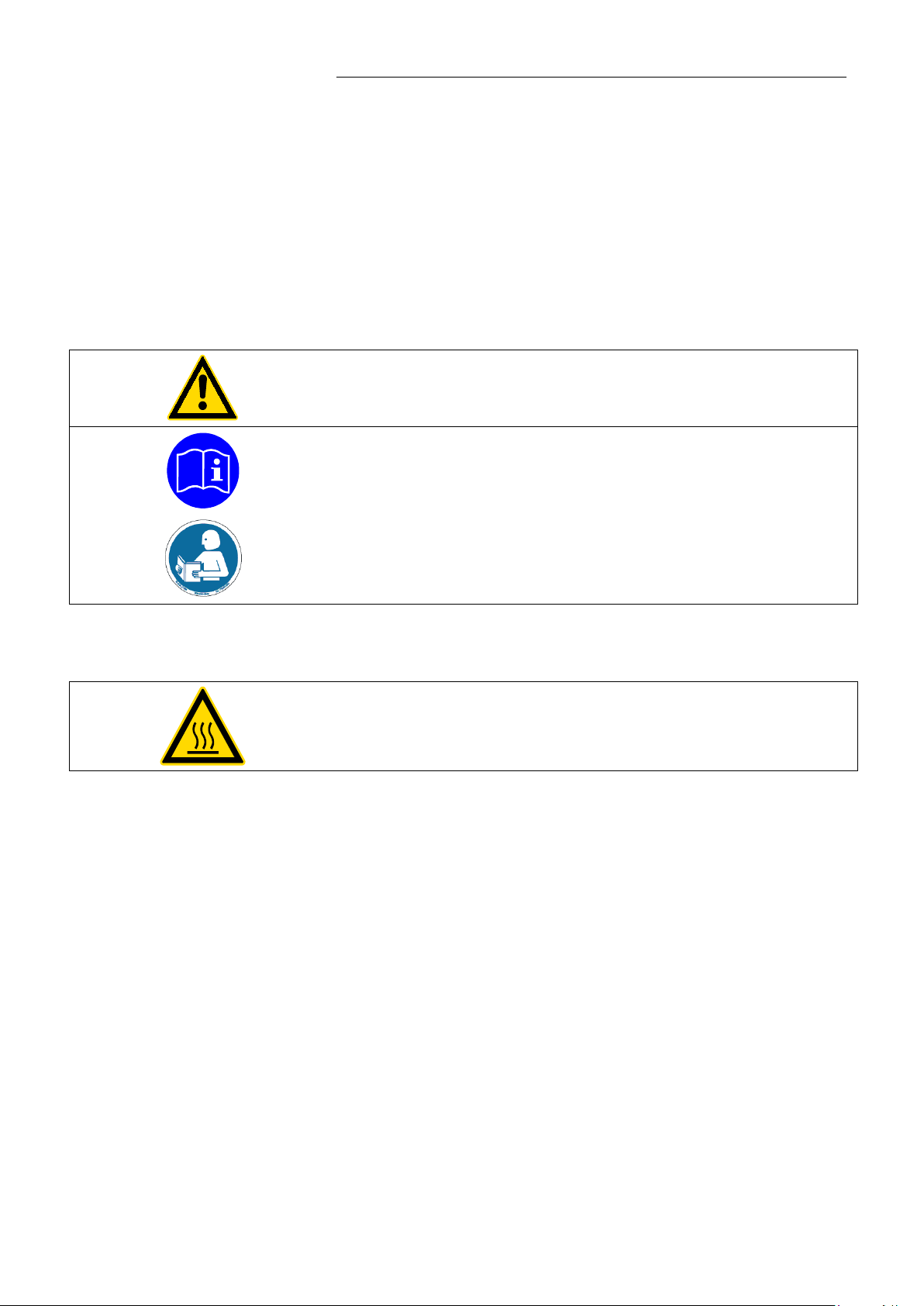
Warning label W00: Colors: yellow, black
Danger area. Attention! Observe instructions.
(operating manual, safety data sheet)
2
or
2
Mandatory label M018: Colors: bl ue , whi te
Carefully read the user information prior to beginning operation.
Scope: EU
Semi S1-0701 Table A1-2 #9
Carefully read the user information prior to beginning operation.
Scope: USA, NAFTA
Particular care and attention is necessary because of the wide operating range.
There are thermal dangers: Burn, scald, hot steam, hot parts and surfaces that can be touched.
Warning label W26: Colors: yellow, black
Hot surf ace warning.
(The label is put on by JULABO)
Observe the instructions in the manuals for instruments of a different make that you connect to the
circulator, particularly the respective safety recommendations. Also observe the pin assignment of
plugs and technical specifications of the products.
7
Page 8

Operator responsibility – Safety recommendation s
Valid in EU countries
Disposal with household waste (unsorted waste) or similar collections of municipal
waste is not permitt ed !
2.1. Disposal
The circul ator contains a back-up battery that supplies voltage to memory chips when the unit is
switched off. Do not dispose of the battery with household waste!
Depending on battery regulations in your country, you might be obliged to give back used or defect
batteries to gathering places.
The product may be used with oil as bath fluid. These oils fully or partially consist of mineral oil or
synthetic oil. For disposal, observe the instructions in the safety data sheets.
These units contains refrigerants– at thi s time consider ed not to have any negati ve effects on the
ozone layer. However, during the long operating period of the unit, disposal prescriptions may change.
So only qualified personnel should take care of disposal.
See the current official journal of the European Union – WEEE directi ve.
Directi v e o f the E ur op ea n Par l i am e nt and of the Council on was te el ectrical and
electro ni c eq ui pm e nt (WEEE).
This direc ti v e r eq ui r es el ec tr i cal a nd electr oni c eq ui pm e nt m arked with a crossedout trash can to be disposed of separately in an environmentally friendly manner.
Contact an authorized waste management company in your country.
2.2. Warranty conditi ons
JULABO GmbH warrants its products against defects in material or in workmanship, when used under
appropriate conditions and in accordance with appropriate operating instructions
Extension of the warr a nty per i o d – fre e of charge
With the ‘1PLUS warranty’ the user receives a free of charge extension to the warranty of up to 24
months, limited to a maximum of 10 000 worki n g h our s .
To apply for thi s extended warranty the us er m ust r egi s ter th e uni t on the JULA BO w eb si te
www.julabo.de, indicating the serial no. The extended warranty will apply from the date of JULABO
GmbH’s original invoice.
JULABO GmbH reserves the right to decide the validity of any warranty claim. In case o f fa ul ts ar is i ng
either due to faulty materials or workmanship, parts will be repaired or replaced free of charge, or a
new replacement unit will be supplied.
Any other c om p ensation claims are excluded from this guar a ntee.
for a period of ONE YEAR.
8
Page 9
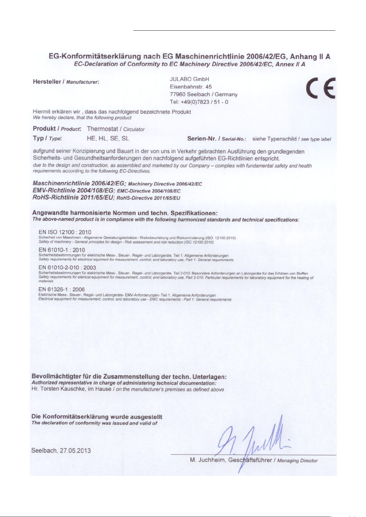
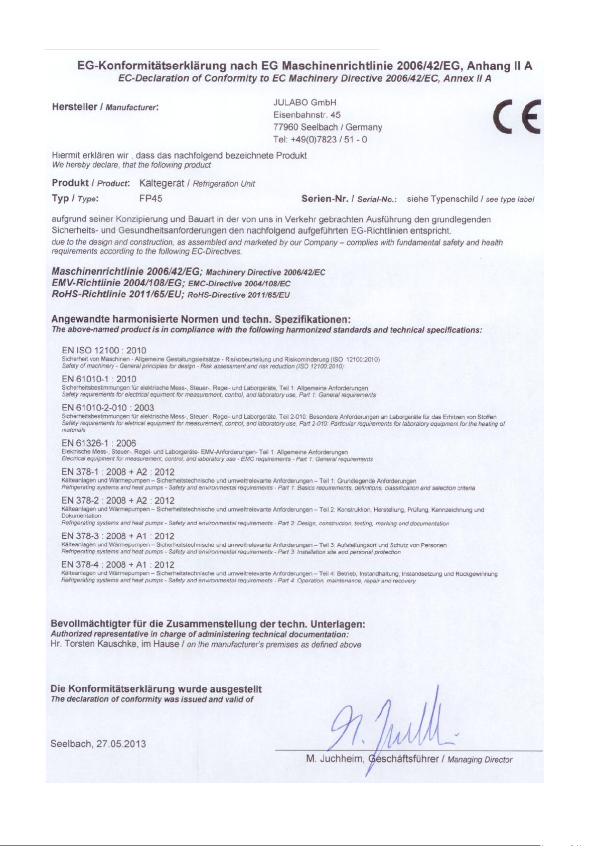
2.3. EC Conformity
HE
9
Page 10
Operator responsibility – Safety recommendation s
10
Page 11

2.4. Technical specifications
FP45-HE
Working temperature range
°C
-42 ... 200
Temperature stability
°C
±0.01
Medium: ethanol
kW
0.85 0.7 0.42 0.08
Refrigerant
R-404A
Overall dimensions (WxDxH)
cm
38x58x69
Bath openi n g (WxL)
cm
23x26
Bath depth
cm
20
Filling volume
liters
18 ... 26
Weight
kg
53 Mains power c o nn ec ti o n 230 V/50 Hz
V/Hz
207-253/50-60
Current dr aw (at 230 V)
A
13
Mains power c o nn ec ti o n 230 V/60 Hz
V/ Hz
207-253/50-60
Current dr aw (at 230 V)
A
13
HE Temperature selection
digital
via keypad
indication on VF D COMFORT-DISPLAY
remote control via PC
indication on monitor
Temperature indication
VFD COMFORT-DISPLAY
Resolution
°C
0.01
Temperature control
ICC - Intelligent Cascade Control
Heater wattage (at 230 V)
kW
2.0 Heater wattage (at 115 V)
kW
1.0 Electronically adj. pump capacity stages
1 ... 4
Flow rate at 0 bar
l/min
22 ... 26
Max. pressure at 0 liters
bar
0.7 Max. suction at 0 liters
bar
0.4 Electrical connections:
See page 12
Ambient temperature
°C
5 … 40
HE
Cooling capacity
All measurements have been carried out at:
rated vol ta ge and freque nc y ambient temperature: 20 °C
Technical changes without prior notification reserved.
°C
+20 0 -20 -30
ATC3 INT/EXT °C ±3 / ±9
11
Page 12

Operator responsibility – Safety recommendation s
Caution:
Electrical connections:
External al ar m devi ce 24-0 V DC / max. 25 mA
Computer interface RS232 or RS485
External Pt100 sensor
Optional for HE, SE
(Orde r N o. 8900100 Electronic module with analog connections)
Programmer input -100 °C to 400 °C = 0 - 10 V or 0 - 20 mA or 4 - 20 mA
Input for the signal of a flow meter or external manipulated variable
Temperature recorder outputs 0 - 10 V (0 V = -100 °C, 10 V = 400 °C)
0 - 20 mA (0 mA = -100 °C, 20 mA = 400 °C)
4 - 20 mA (4 mA = -100 °C, 20 mA = 400 °C)
Standby inp ut for external emergency switch-off
Alarm output for external alarm signal
Safety installations according to IEC 61010-2-010:
Excess temperature protection adjustable from 0 °C ... 320 °C
Low liquid level protection float switch
Classification according to DIN 12876-1 class III
Supplementary safety installations
Early warning system for low level float switch
High temperature warning function optical + audible (in intervals)
Low temperature warning function optical + audible (in intervals)
Supervision of working sensor plausibility control
Reciprocal sensor monitoring between
working and safety sensors difference >35 K
Alarm message optical + audible (permanent)
Warning message optical + audible (in intervals)
Environmental conditions according to IEC 61 010-1:
Use indoors only.
Altitude up to 2000 m - normal zero.
Ambient temperature: see Technical specifications
Humidity:
Max. relative humidity 80% for temperatures up to +31 °C,
linear decrease down to 50% relative humidity at a temperature of +40 °C
Max. mains voltage fluctuations of ±10% are permissible.
Protection class according to IEC 60 529 IP21
The unit corresponds to Class I
Overvoltage category II
Polluti on d egr ee 2
The unit is not suitable for use in explosive environment
EMC requirements according to EN 61326-1
This unit is an ISM device classified in Group 1 (using high frequency for internal purposes), Class A
(industrial and commercial range).
12
Page 13
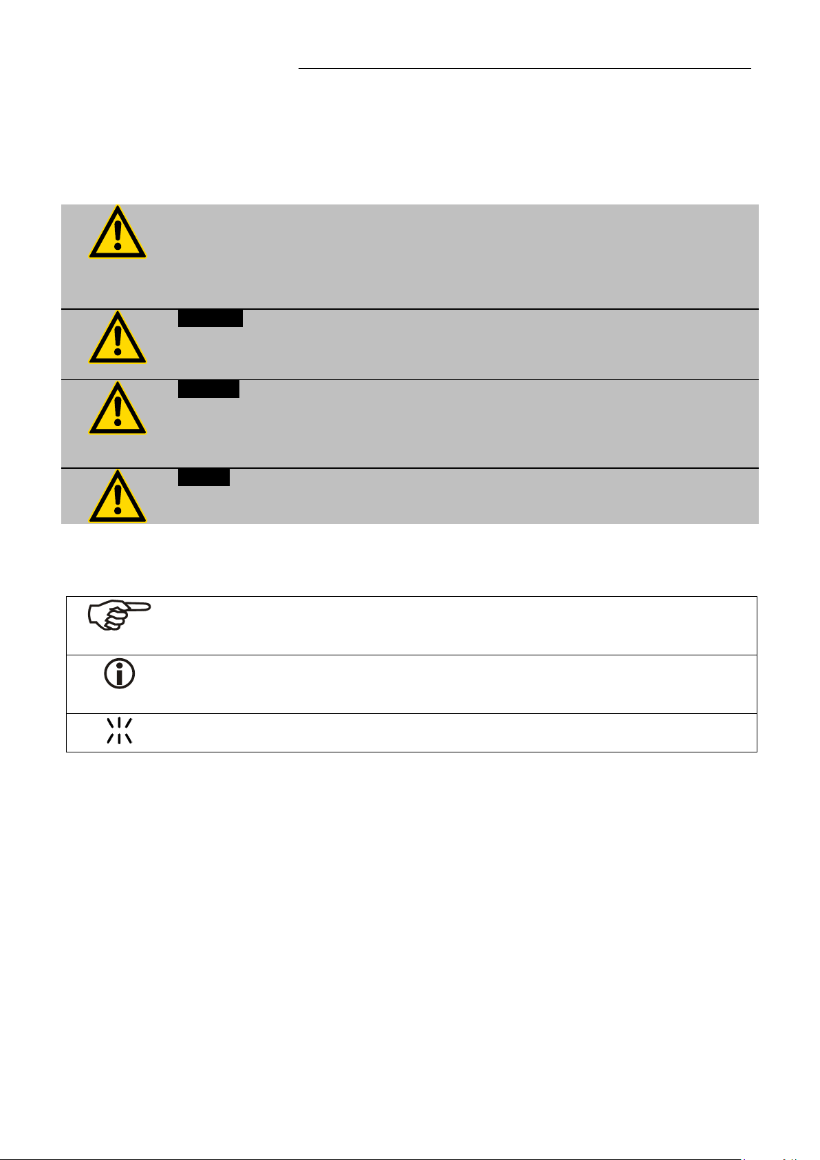
In addition to the safety warnings listed, warnings are posted throughout the operating
manual. T hese warnin gs ar e desi g nated by an exclamati o n mar k inside an eq ui l at er al
Read and follow these important instr uctions for averting dangers.
Warning:
Caution:
injuries could result. A warning of possible property damage may also be contained in
Notice:
This icon is used in the operating instructions to indicate flashing values or parameters
which have t o be set or c on fir m e d.
Operating instructions
3. Safety notes for the user
3.1. Explanation of safety notes
triangle. “Warning of a dangerous situation (Attention! Please follow the
documentation).”
The danger is classified using a signal word.
Describes a possibly highly dang er o us sit uation. If these instr uc tions are not
followed, serious injury and danger to life could result.
Describes a possibly dangerous situation. If this is not avoided, slight or minor
the text.
HE
Describes a possibly harmful situation. If this is not avoided, the product or anything
in its surroundings can be damaged.
3.2. Explanation of other notes
Note!
Draws attention to something special.
Important!
Indicate s usage tips and other use ful in for m ation.
13
Page 14

Safety no tes for the user
Follow the safety instructions to avoid personal injury and property damage. Also, the
Make sure you read and understand all instructions and safety precautions listed in
Check the temperature of the bath fluid prior to draining (e.g., by switching the unit
Some parts of the bath tank and the pump connections may become extremely hot
during continuous operation. Therefore, exercise particular caution when touching
these parts.
3.3. Safety recommendations
valid safety instructions for workplaces must be followed.
• Only connect the unit to a power socket with an earthing contact (PE – protective
earth)!
• The power supply plug serves as a safe disconnecting device from the line and
must alway s be easily accessibl e.
• Place the unit on an even surf ace on a base made of nonflammable material.
• Do not stay in the area below the unit.
•
this manual before installing or operating your unit.
• Set the excess temperature safety installation at least 25 °C below th e fir e p oi nt of
the bath fluid.
• Observe the limited working temperature range when using plastic bath tanks.
• Never operate the unit without bath fluid in the bath.
• Pay atten ti on to the t h er m al expansion of bath oil dur ing heatin g to av oi d
overflowing of the fluid.
• Prevent water from entering the hot bat h oi l .
• Do not drain the bath fluid while it is hot!
on for a short m om en t) .
• Use suitable connecting tubing.
• Avoid sharp bends in the tubing, and mai nt ai n a s u ffic i e nt di stance from
surrounding walls.
• Make sure that the tubing is securely attached.
• Regularly check the tubing for material defects (e.g., for cracks).
• Never operate damaged or leaking units.
• Always tur n o ff the uni t and di s c onnect the mains cable from the power source
before performing any service or maintenance procedures, or before moving the
unit.
• Always turn off the unit and disconnect the mains cable from the power source
before cleaning the unit.
• Always em pty the bath be for e moving the un it.
• Transport the unit with care.
• Sudden jolts or drops may cause damage in the interior of the unit.
• Observe all warning labels.
• Never remove warning labels.
• Never operate units with damaged mains power cables.
• Repairs ar e to be carrie d out only by qualified service personnel.
14
Page 15

HE
Caution:
determi ne the method o f dec o nt amination.
ure protection until the
of the float, it can be manually lowered with a screwdriver for
example.
The temper ature controlling i.e. of fluids in a reactor constitutes normal circulator
practice.
We do not know which substances are contained within these vessels.
Many substances are:
• inflamm a bl e, e as i l y ignited or explosive
• hazardo us to he al th
• enviro nmentally unsafe
i.e.: dangerous
The user alone is responsible for the handling of these substances!
The following questions shall help to recognize possible dangers and to reduce the
risks to a min imum.
• Are all tubes and electrical cables connected and installed?
Note:
shar p edges, hot surfaces in operation, moving machine parts, etc.
• Do dangerous steams or gases arise when heating?
Is an exhaust needed when working?
• What to do when a dangerous substance was spilled on or in the unit?
Before starting to work, obtain information concerning the substance and
Notice: Check the safety installations at least twice a year!
• Excess temperature protection according to IEC 61010-2-010.
With a screwdriver turn back the adjustable excess temperat
shut-down point (actual temperature).
• Low level pr ot ec ti o n according to IEC 61010-2-010.
To check th e function
15
Page 16
Operating controls and functional elements
2
>eprog<*
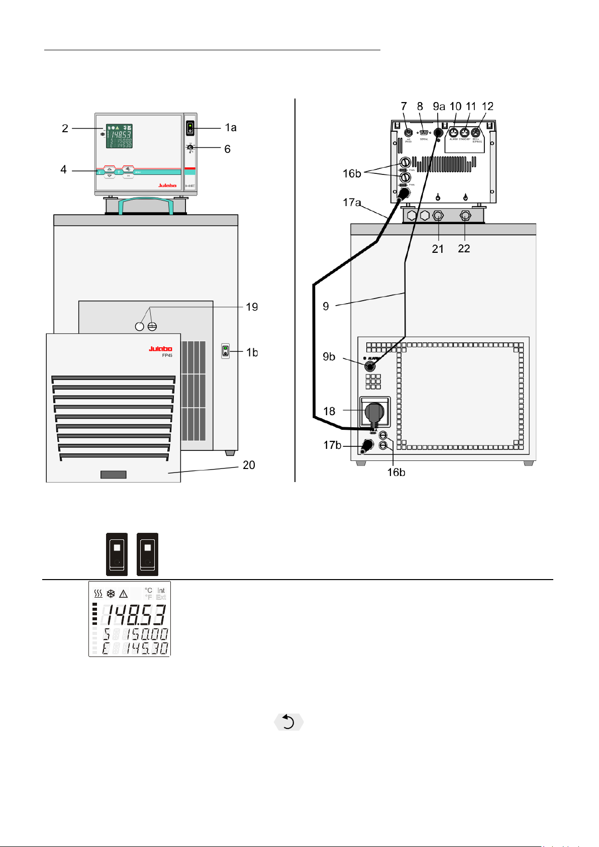
4. Operating controls and functional elements
Front view Rear view
1a
1b
Mains power s wi tc h, il l um inated for circulator
Mains power switch, illuminated for cooling machine
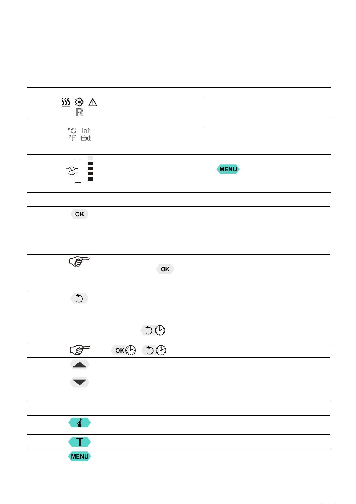
VFD COMFORT-DISPLAY
Header: Control indicators
Line 1: Actual value internal or external
The displ ay is de pe nding on the selected contr ol m ode in th e
menu > Control < (internal or external).
Line 2: Working temp. setpoint, constantly S xxx.xx
Line 3: Actual value (E = external or I = internal)
Alternating with the dis play in line 1
Use the keys
PI Capacity in % - with manipul at ed v ar i a bl e set to > c ontrol<*
PS Capacity in % - with manip ul at ed v ar i a bl e set t o > s er i al< * or
to indicate further values in line 3
16
Page 17
H Heater capacity in Watts
2.1
R
2.2
A beep signals the end of setting
U Mains voltage Volts
F Flow rate in liters/minute
(providing EPROG input set to >Flowrate<)
*refer to >MENU/CONFIG< >CONFIG / ACTVAR>
HE
2.3
4
4.1
Control indicators in the header:
Heating / Cooling / Alarm /
emote control
Control indicators in the header:
Temperature indication Internal or External actual value
Temperature indication in °C (°F not possible on this unit)
Display of set pump pressure stage
Four stages, can be set via the key
Navigation keys
1. Key: >OK< Start / Stop (pump / heater )
2. >OK< in the menu Menu item / sel ec t s u bm en u f or s etti ng
Save set value
Save selec t ed parameter
After the ac ti o ns S tar t , Sto p and ch an ge from VFD Dis pl ay t o standard
display the key
The above graph “front side” shows an example for standard display.
is locked for a short time.
, under >MENU - PUMP<.
4.2
4.3
4.4
4.5
4.6
1. Key: >Return< Stop (pump / heater )
2. >Return< in the menu one menu level down
Correcti on function for param eters or values (pri or to OK)
- icon for „ke ep k ey pr es sed down“.
1. Key: >Up / Down <temperature – increase/decr ease s etpoin t
Push key quickly for single steps,
Keep key pres sed for fast change.
2. >Up/Down< in the menu selection of menu items / paramet ers
Menu keys
Key: start the menu > warning and safety values<
Key: start the menu >temperature setpoints<
Key: display of MENU structure
immediately b ac k t o standard display
17
Page 18
Operating controls and functional elements
7
8
SERIAL
9
10
11
STAND-BY
12
REG+E-PROG
16a
17a
18
Built-in mains outlet for connection of circulator
19
20
21
6
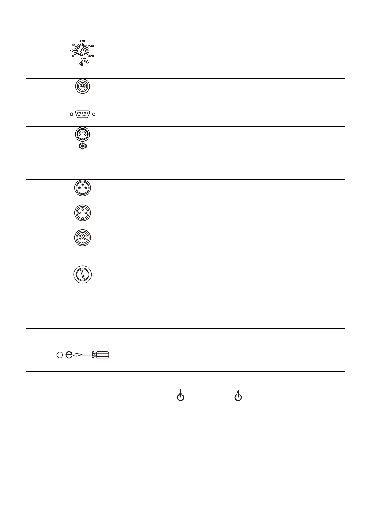
Adjusta bl e ex ce s s t em p er at ur e pr otection accordi ng to IEC 61 010-2-010
Socket for external measurement and control sensor
or external setpoint programming
ext Pt100
Interface RS232: remote control via personal computer
Socket: control cable of JULABO refrigerated circulator
or output for al ar m messages
Option: Electronic module Order No. 8 900 100
Alarm output (for external alarm signal)
ALARM
Standby input (for external emergency switch-off)
16b
17b
22
Programmer input and temperature recorder output
Mains fuses for circulator, T16A
Mains fuses for cooling machine, T10A
Mains power cable with plug for circulator
Mains power cable with plug cooling machine
Drain screw with drain connection
Venting grid, removable
Pump connectors suction pump pressur e pump
18
Page 19
5. Preparations
sufficient air ventilation to ensure the room does not warm up
Caution:
corrosion in the bath, even in stainless steel.
5.1. Installation
HE
• Place the uni t on an ev e n s urface on a pad ma de o f non-
flammable material.
• The place o f ins tal l a ti o n sh ould be large eno ug h and provide
excessively because of the heat the instrument radiates to
the envir onment. (Max. permi s si bl e am bi e nt temperature: 40
°C).
With regar d to a disturbance in the cooling loop (leakage),
the guideline EN 378 prescribes a certain room space to be
available for each kg of refrigerant.
The necessary amount of refrigerant is specified on the type
plate.
> For 0.52 kg of refrigerant R404A, a room spac e o f 1 m
required.
• Keep at least 20 cm of open space on the fron t an d re ar
venting gr i d.
• Do not set up the unit in the immediate vicinity of heat
sources and do not expose to sun light
• Before op er ating the unit after tra ns por t , wait ab ou t one hour
after setting it up. This will allow any oil that has accumulated
laterall y dur i n g tr ansport to flow back dow n thus e ns ur ing
maximum cooling performance of the compressor.
3
is
5.2. Bath fluids
Carefully read the safety data sheet of the bath fluid used, particularly with regard to
the fire poi nt!
If a bath fluid with a fire point of ≤65 °C is used, on l y supervised operation is possible.
Water: The quality of water depends on local conditions.
• Due to the high concentration of lime, hard water is not suitable for temperature
control because it leads to calcification in the bath.
• Ferrous water can cause corrosion - even on stainless steel.
• Chloric water can cause pitting corrosion.
• Distilled and deionized water is unsuitable. Their special properties cause
19
Page 20
Preparations
Bath fluid
Temperature range
soft/decalcified water
5 °C to 80 °C
mixture water/glycol, mixture 1:1
-20°C to 50°C
Description
G
HY
H5
Order Number
10 liters
8 940 124
8 940 104
8 940 106
5 liters
8 940 125
8 940 105
8 940 107
Temperature range
°C
-30 ... 80
-80 ... 55
-50 ...105
Flash poi nt
°C
--
78
124
Fire point
°C
--
80
142
Color
light yellow
clear
clear
Description
H10
H20S
Order Number
10 liters
8 940 114
8 940 108
5 liters
8 940 115
8 940 109
Temperature range
°C
-20 ... 180
0 ... 220
Flash poi nt
°C
190
230
Fire point
°C
216
274
Color
clear
light brown
No liability for use of other bath fluids!
Recommended bath fluids:
JULABO bath fluids
JULABO
JULABO
Thermal
Thermal
See websi te for list of rec om m ended bath fluids.
Thermal
Thermal
Thermal
ATTENTION: The maximum permissible viscosity is 70 mm
Caution:
Fire or other dangers when using bath fluids that are not recommended:
Please contact JULABO before using other than recommended bath fluids.
Use only no naci di c and nonc or r osi v e ba th fl ui ds.
JULABO assumes no liability for damage caused by the selection of an unsuitable
bath liquid.
Unsuit able bath flui ds ar e fl ui ds w hic h , e. g. ,
• are highly vis cous
(much higher than recommended at the respective working temperature)
• have a low viscosity and have creep characteristics
• have corrosive characteristics or
• tend to crack.
•
2
/s.
20
Page 21
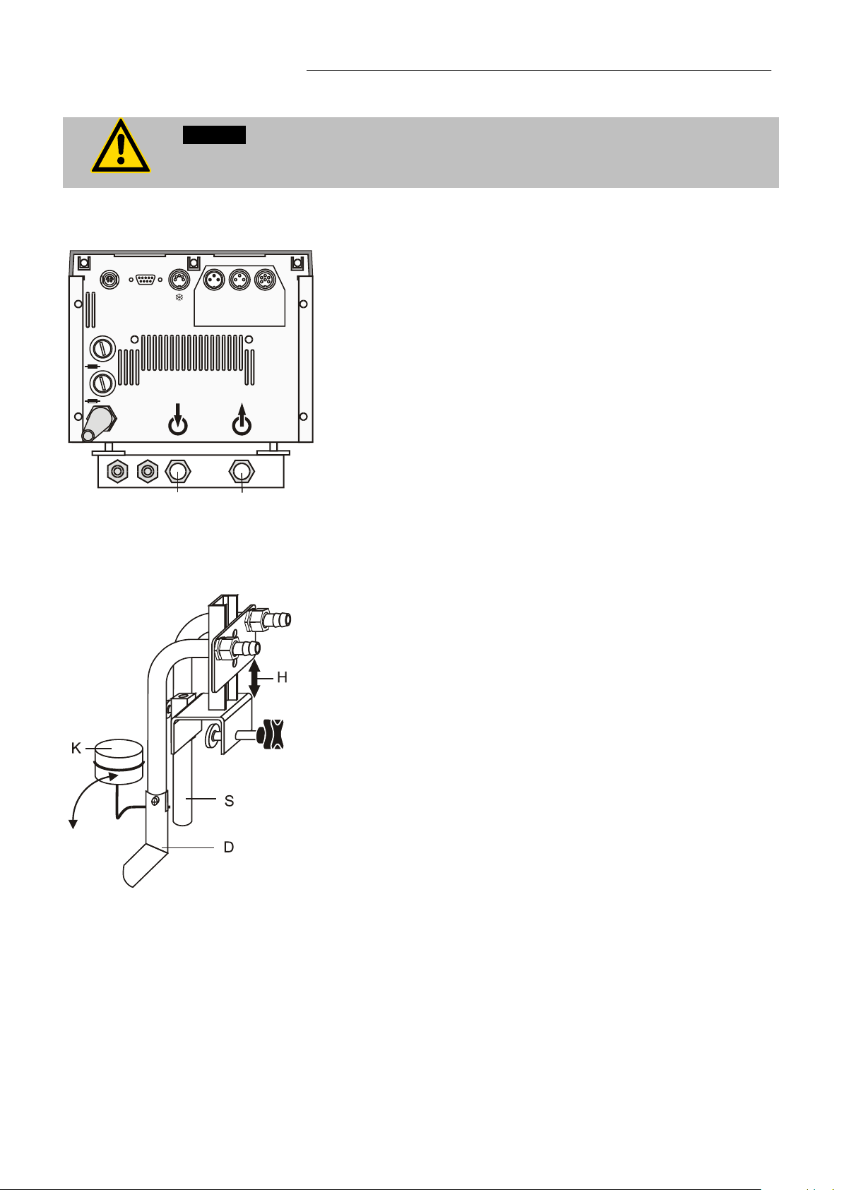
5.3. Temperature application to external systems
with the cap nut.
21 22
Unscrew the M16x1 collar nuts on the pump connectors with
a 19 mm (3/4“) wrench and remove the sealing disks. Using
H = Height adjustment
Caution: Securely attach all tubing to prevent slipping.
If the circulator is operated without external system, close the pump connector (22)
Temperature application to external, closed systems
The circulator is used for temperature application to external,
closed systems (loop circuit) with simultaneous temperature
application in the circulator bath.
•
Pt100
ext
SERIAL
ALARM
STAND-BY
REG+
E-PROG
HE
T16A
the collar nuts, screw on the tubing connection fittings (for
tubing 8 mm or 12 mm in diameter) delivered with the unit
T16A
and tight en fi r mly. (Pressure pump: 22, suction pump: 21)
• Push on the tubings, and secure with tube clamps.
• Attach the t ubings to the connectors of the external closed
system, e.g., an instrument with a pressure-resistant
temperature jacket or a temperature coil, and fasten with
tube clamps to prevent slipping.
Temperature application to external, open systems
The circulator is equipped with both a pressure and suction pump
for external temperature application in open systems.
Differing flow rates of the pressure and suction pumps should be
compensated. To maintain a constant liquid level, the JULABO
„D+S“ Level Adapter is recommended for the external bath tank.
The flow rate of the pressure pump will be then regulated by a
built-in float device. The liquid level may be changed by a height
adjustment on the „D+S “ Lev el Ada pter.
Accessor y : „D +S“ L ev el Ad apter Order No. 8 970 410
Important:
The liquid level should be equal in the internal and external
baths (absolute height).
If you take out samples (for example Erlenmeyer flasks) from
S = Suction pump connection
D = Pressure pump connection
K = Float
the external bath, turn the circulator off with the Start/Stop key.
21
Page 22
Preparations
Order No. Length
Temperature range
8930008 1 m
CR® tubing 8 mm inner dia.
-20 °C to 120 °C
8930012 1 m
CR® tubing 12 mm inner dia.
-20 °C to 120 °C
8930108 1 m
Viton tubing 8 mm inner dia.
-50 °C to 200 °C
8930112 1 m
Viton tubing 12 mm inner dia.
-50 °C to 200 °C
8930410 1 m
Insulati o n for t ubing 8 mm inner dia.
-50 °C to 100 °C
8930412 1 m
Insulati o n for t ubing 12 mm inner dia.
-50 °C to 100 °C
8 930 209 0.5 m
8 930 214 3.0 m
Metal tubing, triple insulated, M16x1
-100 °C to +350 °C
8 930 220 0.5 m
8 930 223 3.0 m
Metal tubing, insulated, M16x1
-50 °C to +200 °C
Warning: Tubing:
A damaged tubing line may cause hot bath fluid to be pumped out within a short time.
Preventive maintenance: Replace the tubing from time to time.
Return flow safety device
If the liquid levels in the circulator bath and the external system are at
5.3.1. Tubing
Recommended tubing:
different heights, overflowing must be prevented after the power has
been turn ed off .
Flood hazard!
For this reason, shut-off valves can be integrated in the loop circuit.
Order No. Description
8 970 456 Shut-off valve (sui ta bl e up to + 9 0 °C)
8 970 457 Shut-off valve (sui ta bl e up to + 2 00 °C )
8 930 210 1.0 m
8 930 211 1.5 m
8 930 221 1.0 m
8 930 222 1.5 m
At high working temperatures the tubing use d for tem perature applicati on and cooling
water supply represents a danger source.
This may result in:
• Burning o f ski n
• Difficul t ies i n br ea thi n g due to hot atmos p here
Safety recommendations
• Employ suitable connecti ng tu bi n g.
• Make sure that the tubing is securely attached.
• Avoid sharp bends in the tubing, and maintain a sufficient distance from
surrounding walls.
• Regularly check the tubing for material defects (e.g. for cracks).
•
22
Page 23
Check the temperature of the bath fluid prior to draining (by switching the unit on
protection.
5.4. Filling / draining
Notice:
• Pay attention to the thermal expa ns i o n o f ba th oi l duri ng heating to avoid
overflowing of the liquid.
• Do not drain the bath fluid while it is hot!
Recommendation: Temperature range 5 °C to 40 °C
for a short moment, for example).
• Store and dispose the used bath fluid according to the laws for env i ronmental
HE
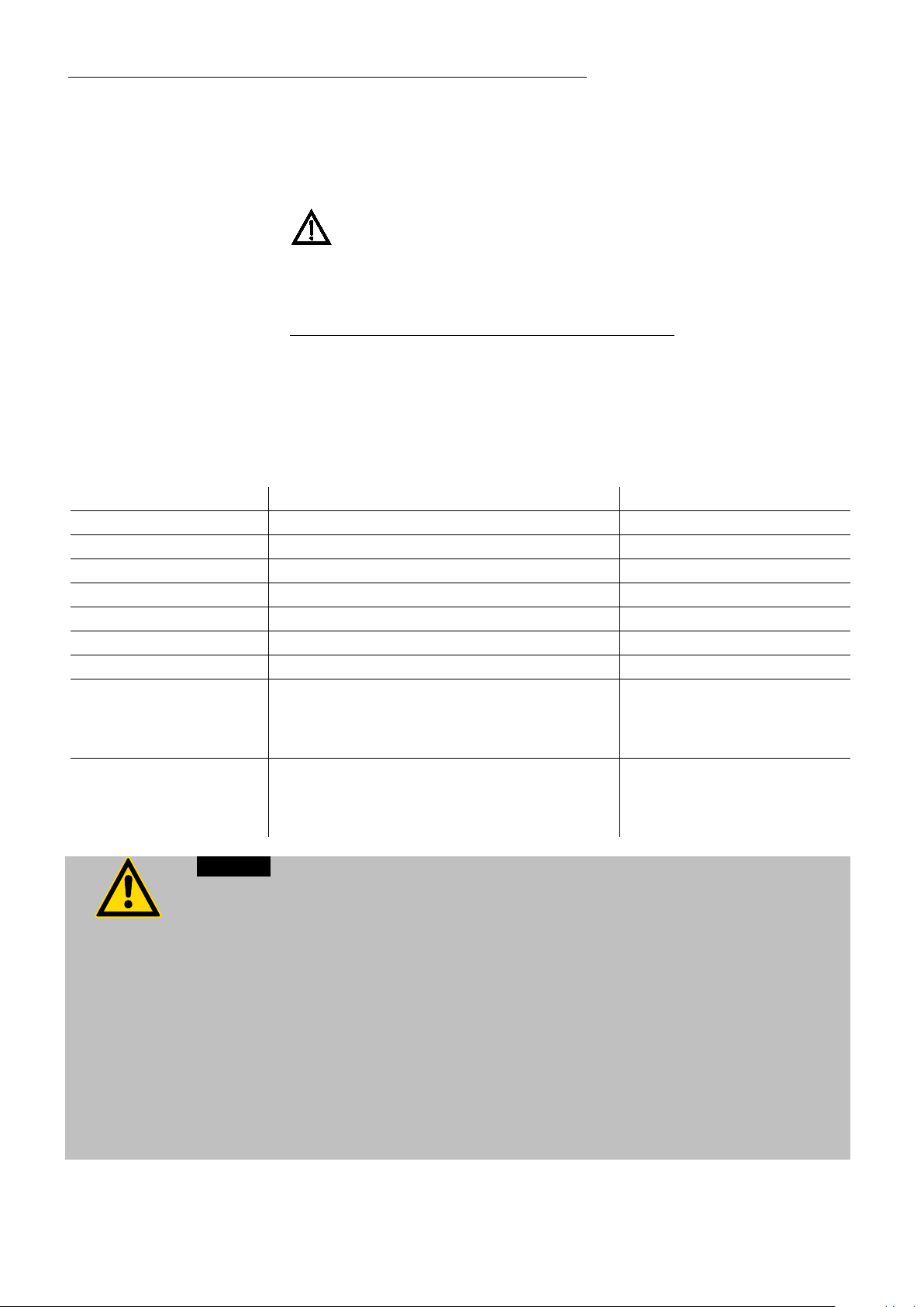
Filling
Take care that no liquid enters the interior of the circulator.
• Recommended maximum filling level with water as bath fluid:
30 mm bel ow t he ta nk rim
• Recommended maximum filling level with bath oils:
40 mm below the tank rim
After filling, immerse the samples in the bath or place the lid on
the bath, in case the opening is not to be used.
The circulator provides an early warning system for low level that
may be triggered when changing samples in the bath.
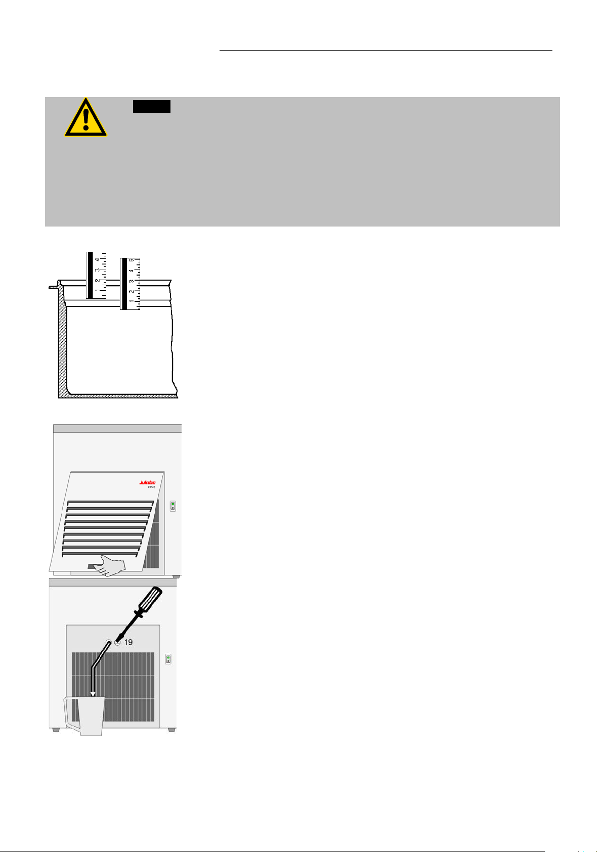
Draining
• Turn off th e cir culator and cooling ma c hi n e.
• Hold the venting grid, pull out and remove.
• Slide a short piece of tu be on to t h e dr ai n por t a nd hol d it in to a
pail.
• Unscrew the drain tap (19) and em pty the unit completely.
• Tighten the drain tap.
23
Page 24
Operating procedures
Caution:
serves as s a fe di s connecting devic e fr om the li n e an d must
We disclaim all liability for damage caused by incorrect line voltages!
Check to make sure that the line voltage matches the supply voltage
specified on the identification plate. Deviations of ±10 % are permissible.
The VFD COMFORT-DISPLAY indicates the message "OFF".
6. Operating procedures
6.1. Power connection
• Only connect the unit to a power socket with earthing contact (PE – protective
earth)!
• The power supply plug
be always easily accessible.
• Never operate equipment with damaged mains power cables.
• Regular l y ch eck th e mains power cables for material defects (e.g. for cracks).
•
• Connect the circulator with mains power cable (17a) to the mains
outlet (18).
• Connect the control cable (9) between the connectors (9a, 9b).
• Connect the refrigerated circulator with mains power cable (17b) to
the mains socket.
6.2. Switching on / Start - Stop
6.2.1. Switching on the circulator
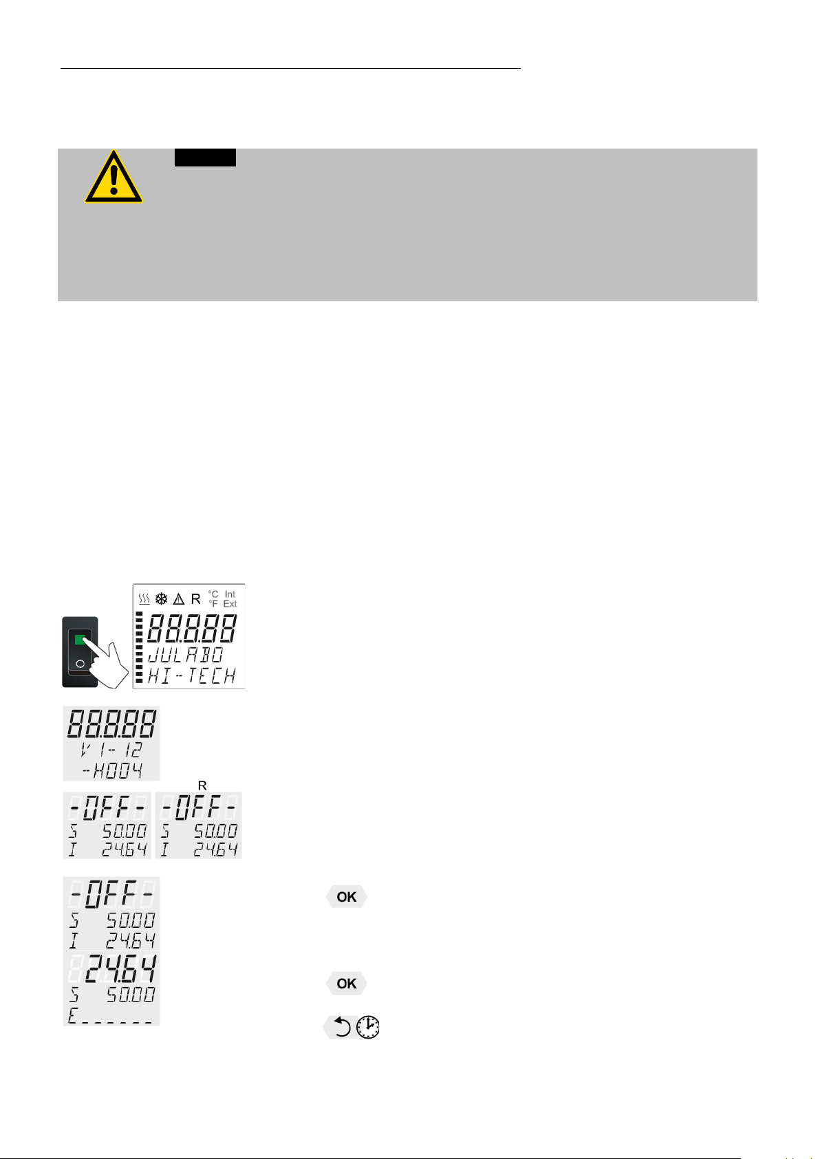
Switching on:
• Turn on the mains power switch (1).
The unit per form s a self-test.
Then the software version (example: V 1.xx) appears. The display
„OFF“ or „R OFF“ indicates the unit is ready to operate.
The circulator enters the operating mode activated before switching
the circulator off:
keypad control mode (manual operati o n)
or
remote control mode (operation via personal computer).
Start:
• Press
The actual bath temperature is displayed on the VFD COMFORTDISPLAY. The circulating pump starts with a slight delay.
Stop:
key.
Press key.
24
or
Keep
key press ed .
Page 25

Switching on:
6.2.2. Switching on the Cooling Machine
• Switch on the cooling machine using the switch (1b) .
Control of the cooling machine:
With the mains switch (1b) turned on, the circulator automatically
switches the cooling machine off and on.
• It is switched off, if:
- the actual working temperature is increased by >30 °C (cooling is
not required).
- the heater operates at full power (>800 W) for longer than 5
minutes.
• It is switched on, if:
- cooling is necessary for maintaining the bath temperature.
After switch-off, the cooling machine automatically switches on only
after a delay o f 5 min utes for protec ting the cooling com pr essor.
HE
To save energy, turn off the cooling machine with the mains switch
(1b) whenever cooling is not required.
25
Page 26
Setting of temperatures
7. Sett in g of te mpera tur e s
7.1. Using the pre-settings in the menu
Werkseinstellungen:
SETPNT 1 25 °C
SETPNT 2 37 °C
SETPNT 3 70 °C
Press the
3 different working temperatures can be adjusted. Their values are freely
selectable within the operating temperature range.
key to call up the menu for temperature selection.
The temperatures can be set in start or stop mode.
Press key if a value is to be retained
Setting of working temperature in the
1. Press the key
2. Select SETPOINT 1 or 2 or 3 using the key
3. Confirm by pressing the
. The value flas h es
key.
menu
or .
The circulator uses the new working temperature value for temperature
control.
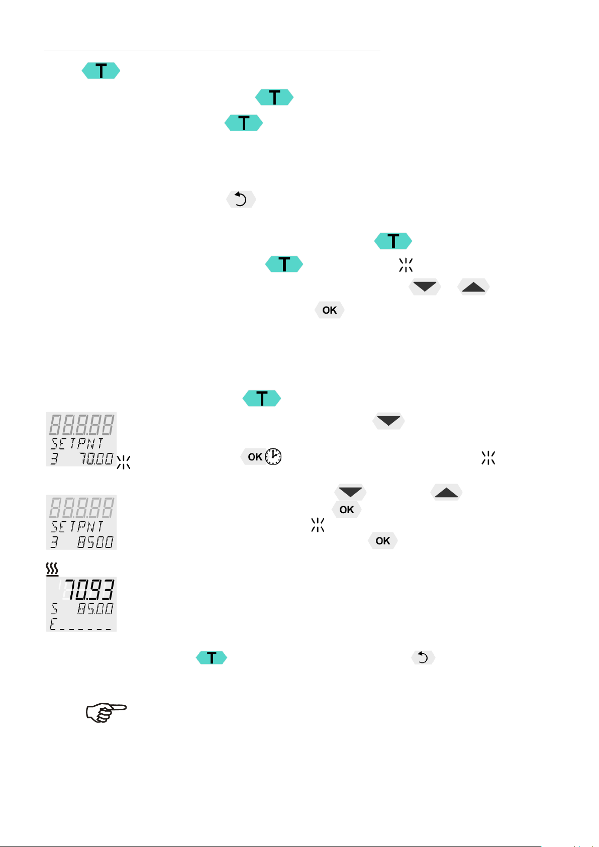
Example: Adjustment/modification of the pre-setting of "SETPOINT 3"
1. Press the
2. Select SETPOINT 3 by pressing the
Example: S ETPNT 3 / 70.00 °C
key.
key.
3. Kee p th e
(example: <70>)
4. Adjust value by pressing the
and confirm by pressing the
The decim al di gi ts fl as h
Confirm once more by pressing the
Example on the left: SET PN T 3 / 85.00 .
key pressed until the integer digits flash .
key and the
key.
and can be adjusted if desired.
key.
key to 85.00 °C
If the active setpoint (SETPNT) is changed, the new value is
immediately used for the control of the working temperature.
The heater co ntr ol i ndicator flashes.
If the other two setpoints (not activated for control) are changed the
MENU has to be le ft by pr ess ing the key after the decimal
digits hav e be en confirm ed
Notice: Refer to SETPOINT MAX / MIN in chapter
9.8. MENU LIMITS
26
Page 27
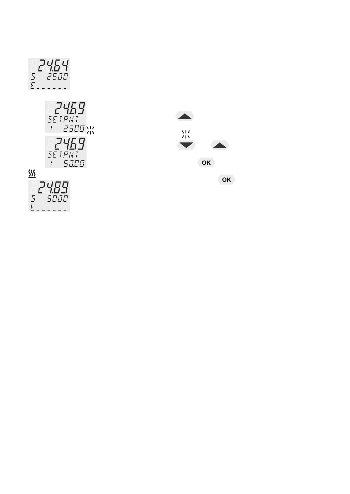
7.2. Direct setting of temperatures
The circulator uses the setpoint of SETPNT 1 or 2 or 3 for temperature
control
The indicated setpoint temperature can be changed directly any time.
Example: change 25.00 °C to 50.00 °C
HE
1. By pressing the key
SETPOINT< example on the left: >SETPNT / 1 25.00°C<.
The integer di git s flash
2. By pressing the keys
50.00 °C and
is confirm e d by pr es si n g t he
The decimal digits flash and can be adjusted if desired.
Confirm once more by pressing the
the circul at or swi tches to the active
(example: <25>).
and
the value is changed to
key.
key.
The circulator uses the new working temperature value for temperature
control.
The temperatures can be set in start or stop mode.
27
Page 28
Safety installations, warning functions
Warning:
Set the excess temperature protection at 5 °C to 10 °C above the working
8. Safet y inst allations, warning functions
Check the safety installations at least twice a year! Refer to ( page 15)
SECVAL
(Securit y Values)
SAFETMP
AL-TYPE
OVERTMP
SUBTEMP
Settings for t h e exc ess temper at ure protec ti o n > SAFETMP<
and for the warning functions for high > OVERTMP< and low >
SUBTEMP< temperature are made in a menu which is called up by
pressing the key
Menu item > AL-TYPE< allows choosing between a warning and
an alarm cut-off for the menu items > OVERTMP< and > SUBTEMP<.
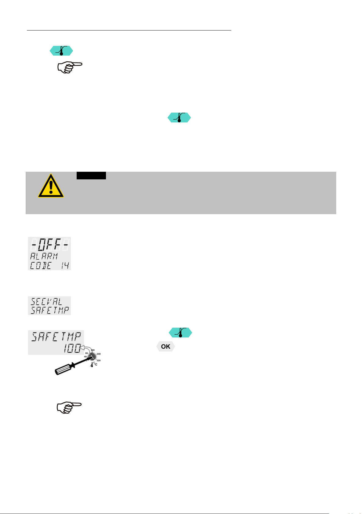
8.1. Excess temperature protection
The excess tem p er ature protection must be set at least 25 °C below the fire point of
the bath fluid used!
In case of wrong setting there is a fire hazard!
We disclaim al l liabi l i ty f or damage caused by wrong set tings!
This excess temperature protection is independent of the control circuit.
When activated heater and circulating pump are completely shut down.
The alarm is indicated by optical and audible signals (continuous tone)
and the error message "ALARM-CODE 14" appears on the VFD
COMFORT-DISPLAY together with the ticker:
> EXCESS TEMPERATURE PROTECTOR ALARM-CHECK
ADJUSTMENT <
Setting range: 20 °C ... 320 °C
.
Rough setting can be effected by using the temperature scale.
Exact setting:
1. Press the key
2. Press the
3. Set th e new shutdown value wit hin 30 s econds using a screwdr i ver .
The value is indicated on the VFD COMFORT-DISPLAY
Example: SAFETMP / 100 °C
Recommendation:
temperature setpoint.
to display menu >SAFETMP<.
key and the set shutdown value is indicated.
28
Page 29
An audible warning sounds (interval tone) and together with the
Warning:
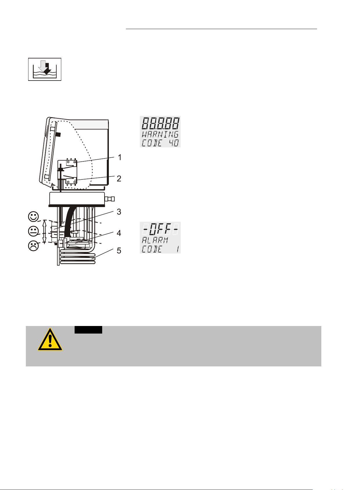
8.1.1. Early war ning system, low level protection
This low level protection is i ndependent of the control circuit and is
divided into two sections:
HE
1. Swi tc h in st ag e 1 recognizes a define d fl ui d lev el .
ticker: > LOW LEVE L WAR N ING-FILL ME DIUM < a message
appears on the VFD COMFORT-DISPLAY:
Refill the bath fluid!
2. Switch in stage 2 recognizes a low fluid level
If stage 2 of the low level protection according to IEC 61010-2-
010 is triggered, a complete, all-pole shutdown of heater and
circulating pump is effected
A continuous alarm sounds and together with the ticker: > LOW
LEVEL ALARM-FILL MEDIUM < a message appears on the
VFD COMFORT-DISPLAY:
.
When adding bath fluid, always us the type of fluid which is ide nti cal with the fluid in
the ba th.
Bath oils must not contain any water and should be pre-heated appr ox im ately to the
current bath temperature! Explosion hazard at high temperatures!
Turn off the unit with the mains switch, refill bath fluid and turn
the un i t on again!
3. Float
4. Circulating pump
5. Heater
29
Page 30
Safety installations, warning functions
Factory setting:
A mere warning function with optical and audible warning signal (interval
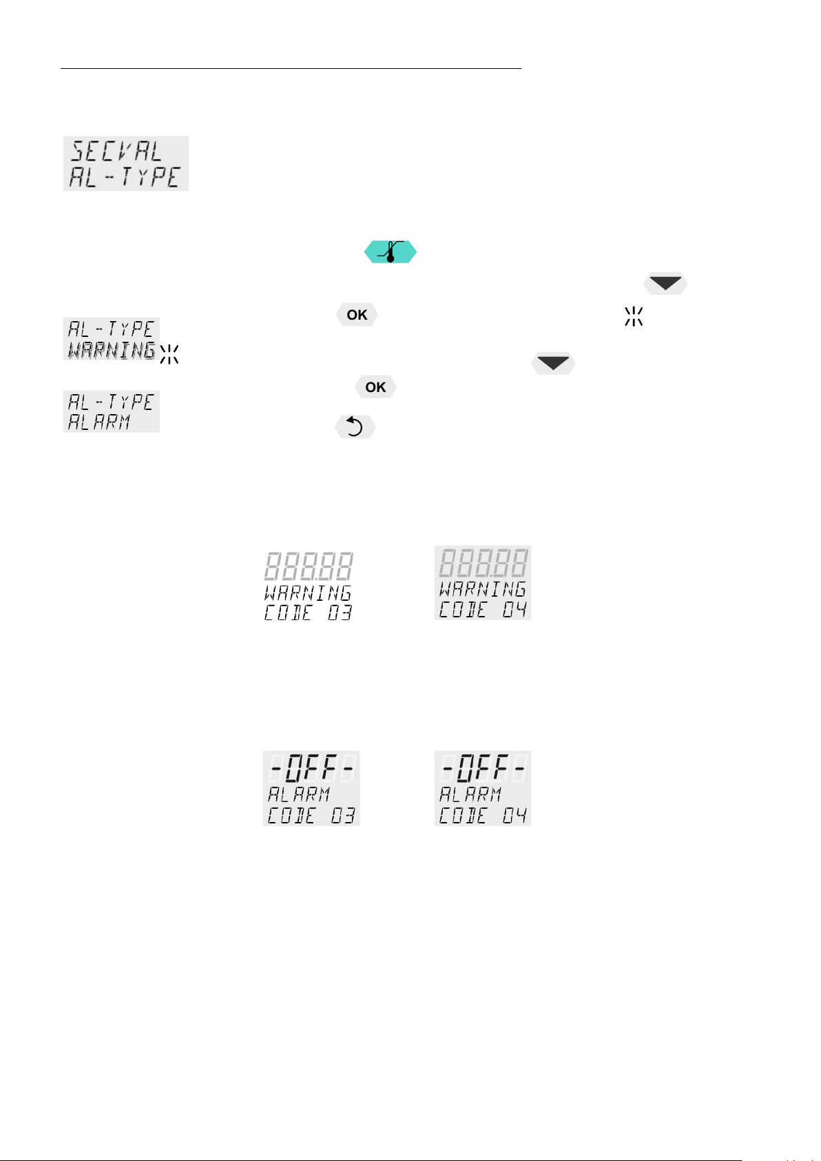
8.2. Switch-over from warning to shutdown function
If a shutdown of functional elements (e.g. heater, circulating pump) is
required when the limit values are exceeded or undercut the circulator can
be changed over from warning function >WARNING< to shutdown function
>ALARM<.
>WARNING<
1. Press the key
2. Select the menu >SECVAL -AL-TYPE< by pressing the
3. Press the
(Example: WARNING)
4. Change the parameter by pressing the
pressing the
or
press the
.
key.
key and the set parameter will flash .
key and confirm by
key.
key if the parameter is to retained.
Setting >WARNING<
tone) A message appears on the VFD COMFORT-DISPLAY:
or
OVERTMP SUBTEMP
• Setting >ALARM<
Temperature limit with shutdown of heater and circulating pump.
An audible alarm sounds (continuous tone) and a message appears on
the VFD COMFORT-DISPLAY:
or
OVERTMP SUBTEMP
30
Page 31
Set the over temperature warning value >OVERTMP< 5 °C to 10 °C above
Set the sub temperature warning value >SUBTMP< 5 °C to 10 °C below the
8.3. Over and Sub temperature warning function
HE
Over temperature
Sub temperature
If the observance of a working temperature value >SETP< has to be
supervised for a sensitive temperature application, then set over and sub
temperature warning values. In the example below the SETPOINT 85 °C is
surrounded by the values OVERTMP 87 °C and SUBTEMP 83 °C. The
electronics immediately register if the actual temperature breaches one of
the set limit values. The resulting reaction is defined in a further menu item.
(See chapt er 8.2. )
1. Press the key
.
2. By pressing the
>SUBTEMP<.
or
key select the menu >OVERTMP< or
1. Press the key . Th e in te ger di gi ts f lash
2. Change the values to 87. °C and/or 83. °C by pressing the and
key and confirm with the key.
The decimal digits flash and can be adjusted if desired.
Confirm once more by pressing the
See above ex amples.
• The warning functions are only activated if the actual bath temperature
remains wi t hi n th e set limit values for 3 seconds after switch-on.
Recommendation:
the working temperature setpoint.
working temperature setpoint.
key.
31
Page 32

Menu functions
9. Menu functions
Menu level 1
1. Ope n the me nu by pr ess ing the
2. Use the
3. Press the
Press the
The term „Menu functions“ refers to settings such as
Start pro gr am Page 33
Administration and creation of programs Page 36
Electronically adjustable pump capacity Page 38
Configuration of the unit Page 39
REMOTE – on / off (remote control via RS232)
AUTOST – AUTOSTART on / off
OFF-MODE – pump on / off
TIME / DATE – s et ting time and date
RESET – factory settings
keys to scroll in menu level 1.
key to change to menu level 2.
key if settings are to be retained.
key.
Control characteristics and parameters Page 43
C-TYPE – Internal or external control
DYNAMICS - internal
Control parameter - XP-, TN-, TV- INTERNAL
Control parameter - XP-, TN-, TV- XPU-, EXTERNAL
Adjustable interface parameters Page 49
BAUD RATE, PARITY, HANDSHAKE
ATC - Absolute Temperature Calibration, Page 50
Sensor calibration INTERNAL SENSOR,
Sensor calibration EXTERNAL SENSOR
3-point calibration
Limitati o ns o f temp er ature and capacity Page 56
SETPOINT MAX / MIN - Maximum and minimum setpoint
HEAT MAX – Set maximum heating
COOLING MAX – Set maximum cooling
INTERN MAX / MIN – Limitation o f the tem perature range
BAND HIGH / LOW – Band limit
32
Page 33

Menu level 1
Analog inputs/outputs Page 59
This menu will start a previously set program.
Correcti o n function for paramet er s or val u es ( pr i or to OK)
HE
Recorder output – CHANNEL 1, 2, 3
EPROG – External programmer input
EX-STBY - STAND-BY input
ALARM - output
9.1. MENU PROGRAM – START
Start-Menu
Requirements:
1. Create a program. (refer to next chapter)
2. Return to the Start-MENU and confirm the desired setting of each
MENU item with the key
3. Set a start time (>TIME< >DATE< >YEAR<) if the program is to be
started by the internal timer.
Menu level 1
Level 2 Parameter level
Press the key if a parameter is to be retained.
> STEP< Program start at section 1 … 10
> RUNS < Number of repet it i o ns 1 .. . 99
> END< Status at en d o f pro gr am (ST D BY /SETPNT)
Standby or last setpoint
> GO < Time of start (NOW/TIME R)
• Set program step with
example: STEP 1
and
• Set number o f runs with
example: 1 ru n
and
• Set desir ed parameters with
or
(STDBY / SETPNT)
Parameter STanDBY: the circulator switches to –
OFF-.
Parameter SETPoiNT: the circulator constantly
keeps the temperature at the value of the last step.
and .
33
Page 34

Menu functions
Submenu TIMER
Level 2 Parameter level
oer
Parameter level
• Confirm >NOW< with the key and the program
will start immed iately
or
start at the set time under paramet er (TIMER ).
Set time in the ex ample below:
09. August 20 09, 11:15 hrs
set the time for the start of the program in the
submenu >TIMER<.
>TIME< hours/minutes (hh:mm ) , s et bot h v al u es one
after the other and confirm
• hours flas h, set by pressi ng
+
minutes flash, set by pressing
+
>DATE< day/months (TT/MM), set both values one after
the other and confirm.
• day flashes, set by pressing
+
month flas h es , s et by pr es sing
>YEAR< year
• Set the year with
+
and .
The program star ts at the set time.
Display of time until start:
In line 3 the notice >TIMER< and the set values for „TIME“ and
„DATE/Y EAR “ ar e al ter n ately indicated
Check the correct setting of the internal real time clock if required
(see MENU CONFIG)
34
Page 35

HE
The started program
D2
After the start the program will indicate the currently calculated setpoint in line
Termination / Interruption of a program
2
S XX.XX. The value increases within the time period >TSLICE< until the
target temperature >SETPNT< of the section is reached.
If the time period in a section is set to „0“, the next section will not begin until
the target temperature has been reached.
A
B
C1
C2
D1
Use the edit keys
approximately every 4 seconds between the current section (STEP XX) and
the
A remaining time of the section
B remaining time of the program
C current bath temperature
I xxx.xx - inter nal actual value or
E xxx.xx – external actual value
D RUN – the program has started or
PAUSE – th e pr o gr ess o f th e pr ogr am h as been interrupted by pressing
the
remain at the last calculated setpoint
Continue with the
key. While the time is stopped the temperature will constantly
to scroll to line 3. The display changes
key.
The program can be terminated any time by pressi ng the key .
In case of power failure the program is interrupted.
The circulator switches to –OFF- .
If the AUTOSTART-function is activated the programmer starts again at
the point in time approx. 5 minutes prior to the interruption. However, an
uncontrolled change of the bath temperature has occurred.
35
Page 36

Menu functions
The integrated programmer permits fast and easy programming of setpoint
25
50
10 20 30 40 50 60 10 20 30 40 50 60 10
[min]
75
100
150
200
°C
t
Step 1 2 4
6 8
retroac ti vel y an d the integra te d in to t h e pr ogram.
9.2. MENU PROGRAM – creation, administration
Menu level 1
1 program
10 sections
temperature sequences. This temperature sequence is called program. A
program is composed of individual sections (STEP). The sections are defined
by duration (TSLICE) and target temperature. The target temperature is the
setpoint (SETPNT), which is achieved at the end of a section. The programmer
calcula tes th e tem perature ramp from the difference in time an d tem p er ature.
STEP (Nr.) 1 2 4 6 8
SETPNT (°C) 100 180 180 75 75
TIME (hh.mm) 00:20 00.10 00:20 00:50 00:20
Graph1
Sections without set value and time are skipped. They can be defined
36
Page 37

Level 2
Level 3
Parameter level
Menu level 1
>EDIT< Create , adm i ni ster program
> STEP< Program step (1 ... 10)
>SETPNT < Temperature setpoint of step ...
>TSLICE< Duration of step ...
> DELETE< delete program step (01 … 10, ALL)
Press key, if a parameter is to be retained.
Correcti o n function for paramet er s or val u es ( pr i or to OK)
• Set program step with
(Example: EDIT STEP 01)
For STEP 01 the values for SETPOINT 01 and
TSLICE 01 ar e s et on e a ft er the other
and
(STEP 1 … 10)
HE
• Integer digits flash, set by pressing
(values within working temp. range)
+
• Decimal digits flash, set by pressing
+
(time slice)
• Set durati o n by pr es si ng and
Delete program
Program steps can be deleted individually or
entirely. ( STEP 01, 02,… 10, ALL).
• Set parameters by pressing and
37
Page 38

Menu functions
9.3. MENU PUMP - Setting of pump pressure
The pressure of the circulating pump is adjustable in four stages. After
setting, the VFD COMFORT-DISPLAY indicates the corresponding value.
Adjusta bl e pump capaci ty stage 1 ... 4
Examples:
Soll Ist
Illuminated display:
for pump pressure
Adjusted:Display for the adj usted pump pressur e s tag e in the –OFF-
mode.
Effective: Display for the effecti ve pump pressure sta ge (r o tation
Factory setting:
stage 1
speed) a ft er st ar t.
For protecting the pump motor, the rotation speed (i.e. the pump pressure
stage) changes with the load applied.
Example: The viscosity of the bath fluid (i.e. the load applied to the pump
motor) changes with the working temperature in the bath.
Flow rate: 22 ... 26 l/min
Pump capacity stage 1 2 3 4
Pump pressure [bar] 0.4 0.5 0.6 0.7
Suction pump [bar] 0.2 0.26 0.33 0.4
Total capacity [bar] 0.6 0.76 0.93 1.1
in a loop circuit
1. Press the
2. Select the menu >PUMP< pressing the
pressing the
The set par am et er flashes (example: >LEVEL 2<)
key.
key
key and confirm by
38
3. Change the parameter by pressing
or
Press the
key.
key if the parameter is to be retained.
and confirm b y press ing the
Page 39

9.4. MENU CONFIG - Configuration of unit
Menu level 1
A RESET can be effected only in the >OFF< mode.
Switch off circulator by pressing the
CONFIGURATION.
HE
key and call up the menu
or
or
or
Level 2 Parameter level
Press the key if a parameter is to be
retained. Correc ti o n func tion for parameter s and
values (prior to OK).
• Switch on and off remote control by pressing
and
Control display in the topline
for Remote
For remote control refer to 72
Connect RS23 2 with PC.
• Switch over s et point setti ng by pr ess ing
and
OFF –Setpoint setting with the navigation keys
or
Setpoint setting via the analog socket „ext. Pt100
or
analog socket >REG+EPROG<
• Switch on and off autostart by pressing
or
AUTOSTART on = on
AUTOSTART off = off
See WARNING page 41
and
• Switch on and off OFFMODE by pressing
or
PUMP ON continuous operation of circulating pump
PUMP OFF circulating pump is linked to Start/Stop
and
• Switch over the input variable by pressing
or
and
Programmin g o f vari ables for the paramet er s >
or
SERIAL < or > EPROG < is only accepted, if the
unit is in Start mode
39
Page 40

Menu functions
Level 2
Level 3
Parameter level
• Hours flash, set by pressing
• Minutes flash, set by pressing
• Day flashe s , s et by pr es si n g
• Month fl ash es , s et by pr es sing
• Year flashes, set by pressing
+
+
+
+
+
• Return to factory settings by pressing
RESET returns all set values to the factory setting
except for dat e and time.
A RESET can be effected only in the –OFF- mode.
During the mess age –RUN- all parameters are
9.4.1. Remote control via the serial interface
Factory setting : OFF
The control electronics offer two ways of adjusting a setpoint.
1. Adjustment of setpoint using the keypad
or the integrated programmer.
2. Adjustment of setpoint via the serial interface RS232 using a PC or a
superordinated process control system.
The topline of the VFD-DISPLAY shows a br i ght „R“ for remote
control; - remote co ntr ol di sc o nti n ued.
RS232
IMPORTANT: additional measures for remote control
Connect the circulator to the PC using an interface cable.
Check the int erface parameters of both inter faces (circulator an d PC)
and make sure they match.
(refer to 12.1. Setup for remote controll page 72)
reset to factory set tings.
40
Page 41

9.4.2. Keypad control or setpoint setting via the analog input
Notice:
accordance with the NAMUR recommendations. This means for the start
start of the circulator by pressing the mains switch or using a timer.
HE
Factory setting:: OFF
The selected mode is
indicated on the VFD
COMFORT-DISPLAY
OFF
PT100
EPROG
>
>
In addition to the serial interface via remote control the circulator offers
the possibility to adjust the setpoint via analog interface >ext. Pt100< or
>REG+E-PROG<.
OFF - Setpoint setting with the navigation keys
o r the integrated programmer.
PT100 - Setpoint setting via the analog socket „ext. Pt100“ using an
external tem p er ature sensor or an appr opr i a te v ol t age/current
source.
EPROG - Ca n onl y be adjusted when an elec t r onic module with analog
connections is used (option).
Setpoint setting via the analog interface REG+E-PROG connection
with an external voltage or current source or a programmer.
Important:
Connect the external voltage or current source or a programmer to
the circulator via the socket REG+E-PROG (see page 63).
In the menu >MENU IN/OUT< set the par ameter >EPROGINPUT< and the input variables >EPROG-SIGNAL< (see page 63).
The E-Prog input can only be used either under menu item >SP
EXT < or under menu item >ACTVAR<
(see page 42).
9.4.3. AUTOSTART
Warning:
For superv is e d or uns u per vi sed operation wit h th e “AU T OSTART“ function avoid any
hazardous situation to persons or property
Take care to fully observe the safety and warning functions of the circulator.
Factory settings: OFF
The circulator has been configured and delivered by JULABO in
mode that th e uni t m us t en ter a s a fe operating status aft er a pow er
failure. This s a fe op er at ing status is indicated by the message „OFF“ or
„R OFF“ on the VFD COMFORT-DISPLAY.
A complet e, al l -pole shutdown of the main functional elements such as
heater an d pump motor is e ff ected.
The values set on the circulator remain saved and the unit is restarted by
pressing the start/stop key in manual control.
In remote control mode the values need to be resent by the PC via the
interface.
If such a safety standard is not required, the NAMUR recommendations
can be bypassed with the AUTOST AR T function thus allowing a direct
41
Page 42
Menu functions
The heater or the connected cooling unit receives the control
The heater or the connected cooling unit receives the control
control. The permissible maximum temperature can be exceeded. The user has to take
Materi al s , suc h as gas kets or insulations for exampl e, m ay be damaged or destroye d, i f
9.4.4. OFF-MODE
Factory setting:
PMP OFF
Usually the circulating pump is controlled with the key
start/stop command. If the circulating pump is to work in the –OFFmode, the adjustment can be set in a sub-menu.
The pump motor will be shutdown in case of alarm anyhow.
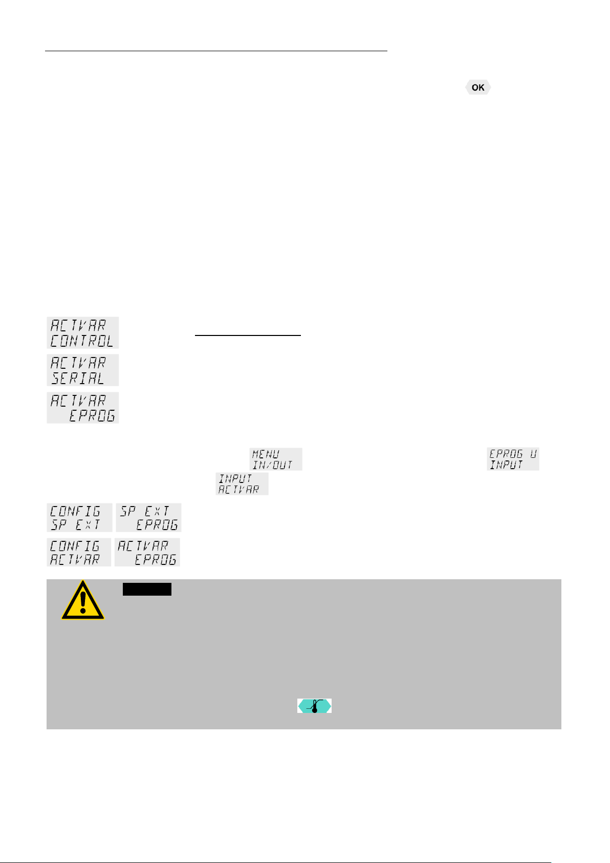
9.4.5. ACTVAR - actuating variable
Factory setting:
CONTROL
The variable (ACTuating VARiable) corresponds to the extent to which
the heater or cooling unit of the circulator is controlled. Heat or cold is
applied to the bath according to this variable. If this happens with the
control electronics of the circulator, called > CONTROL < in this
particular case, the bath temperature is exactly heated and maintained
constant at the adjusted setpoint.
Programming of variables for the parameters > SERIAL < or >
EPROG < is only accepted, if the unit is in Start mode.
Possibl e par ameters:
CONTROL – The internal control electronics of the circulator controls
the heater und the connected cooling unit. Self-tuning is possible.
SERIAL –
signal via the serial interface. Self-tuning is not possible.
or the
Warning:
The working temperature range of the circulator is determined during configuration. If
set to >CONTROL<, this range cannot be exceeded.
If se t to > SERIAL < and > EPROG <, heat or cold is applied to the bath without
adequat e pr ec a utions for temperat ur e control.
the permissible maximum temperature is exceeded.
The safety and warnin g f unc t ions > < of the instrument must always be used to
their full est capacit y .
EPROG -
signal via the E-Prog input. Self-tuning is not possible.
Important:
Under
(refer to pa ge 63).
Note:
The E-Prog input can only be used either under menu item
>SP EXT< (refer t o page 41) or under menu item > ACTVAR <.
set the input variable >EPROG U/I< to
42
Page 43

9.4.6. Setting of clock and date
The internal real time clock allows starting a program any time. The clock
Level 2
Parameter level
is set to the local mean time (MEZ) at the factory.
If the unit is operated in a different time zone, the clock can be
adjusted in this menu.
HE
9.4.7. RESET – Factory settings
Change summer/winter time in this menu
A Reset will ret ur n al l values to factory sett ing except for da t e an d ti m e.
A RESET ca n be effected in the >OFF < mode on ly.
9.5. MENU CONTROL – Control characteristics and parameters
Menu level 1
The circulator is qualified for internal and external temperature control
The switchover is carried out in the menu >C-TYPE< .(INT o r EXT).
Switch off the circulator by pressing the key
menu CONFIGURATION.
For external temperature control and measurement connect a Pt100
external sensor to the socket at the rear of the circulator.
Press the key if a parameter is to be retained. Corr ecti on function
for parameters or values (prior to OK)
and call up the
The parameter flashes, switch by pres si n g
or
The control type can be adjusted in the -OFF-
mode only.
Depending on the adjustment only the active
parameter s ar e displayed.
The parameter flashes, switch by pres si n g
or
OFF - no selftuning.
or
ONCE - single selftuning (factory setting)
ALWAYS - continual selftuning.
and
and
43
Page 44

Menu functions
C-TYPE INTER NAL
C-TYPE EXTERNAL
0.1 … 99.9
Level 2 Parameter level
or
0.1 … 99.9
3 … 9999
0 … 999
• The param et er flashes, switch by pressing
and
This parameter affects the temperature sequence
in case of internal control.
• The param et er flashes, set by pressin g
•
The param et er flashes, set by pressin g
+
+
• The parameter flashes, set by pr ess i n g
+
• The param et er flashes, set by pressin g
0.1 … 99.9
+
• The param et er flashes, set by pressin g
3 … 9999
+
• The param et er flashes, set by pressing
0 … 999
+
• The param et er flashes, set by pressin g
+
44
Page 45
9.5.1. CONTROL – Contr o l INTERNAL / EXTERNAL
(See pag e 50).
Attention:
circuit
Switchover can only be effected if a Pt100 external sensor is
connected.
Pt100
Factory setting: INT
IMPORTANT: Additional measures for external temperature control
Suggested settings for external temperature control:
BAND HIGH / LOW and INTERN MAX / MIN
see chapter >MENU LIMITS<.
Sensor calibration of the Pt100 external sensor is carried out in the
menu >ADJUST<, submenu >ATC SENOR - EXT<; set ATC
STATUS< to >OFF<
Place the external sensor into the temperature-controlled medium and securely fix the
sensor.
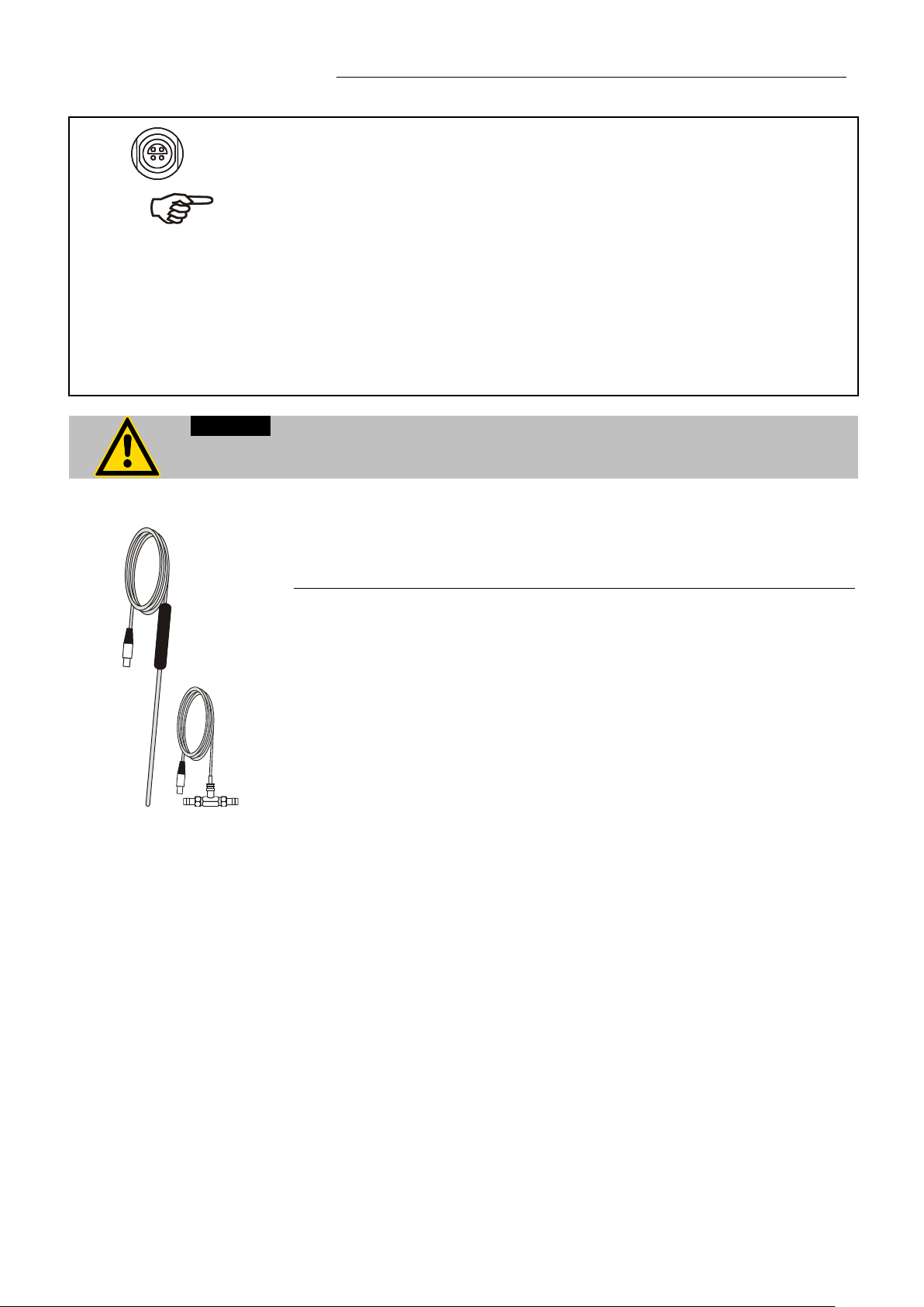
Accessory: Pt100 external sen s or
Order No. Description Material Cable
8981003 200x6 mm Ø, stainless steel 1.5 m
8981005 200x6 mm Ø, glass 1.5 m
8981006 20x2 mm Ø, stainless steel 1.5 m
8981010 300x6 mm Ø, stainless steel 1.5 m
8981015 300x6 mm Ø, stainless steel / PTFE coated 3 m
8981013 600x6 mm Ø, stainless steel / PTFE coated 3 m
8981016 900x6 mm Ø, stainless steel / PTFE coated 3 m
8981014 1200x6 mm Ø, stainl ess steel / PTFE coated 3 m
8981103 Extension cable for Pt100 sensor 3.5 m
8981020 M+R in-line Pt100 sensor
Pt100 M+R
The M+R in-line Pt100 sensor is a flow sensor and can be installed loop
HE
45
Page 46
Menu functions
The control parameters ascertained during the last identification are
The instrument performs a single selftuning of the controlled system
t
APER
NORM
Setpoint
t
APER
NORM
temperature ramp
temp. stability
Setpoint change: The temperature increases at
9.5.2. SELFTUNING
Selftuning:
When performing a selftuning for the controlled system (temperature
application system), the control parameters Xp, Tn and Tv are
automatically determined and stored.
Possibl e par ameters:
OFF - no selftuning
used for cont r ol purposes.
ONCE - single selftuning (factory setting)
after each s tar t wi th the key or after receiving a start
command via the interface.
ALWAYS - continual selftuning
The instrument performs a selftuning of the controlled system
whenever a new setpoint is to be reached.
Use this setting only when the temperature application system
changes per manently.
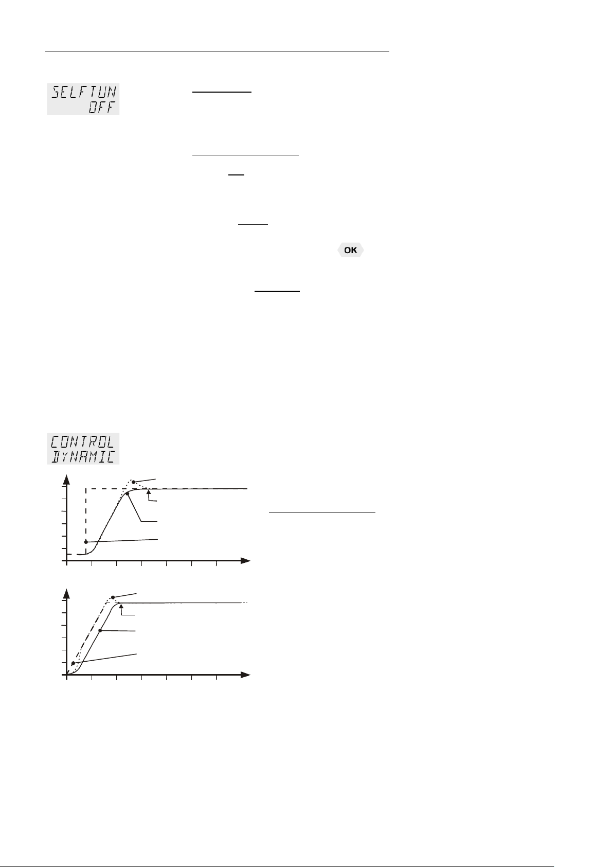
9.5.3. Dynamic internal
This parameter a ffects th e temperature sequence only in
case of int er nal c o ntr ol .
Factory setting: APER (aperiodic)
°C
temp. stability
°C
Possibl e par ameters:
NORM Allows for reaching the setpoint faster – with
setpoint change or ramp function – but
overshooting of up to 5 % is possible.
APER Ramp function: the increase of temperature
occurs tem p or al l y o f fset an d achieves the
target temperature without overshooting.
the same rate, the target temperature is
achieved without overshooting.
W it h both set tings constant temperature is achieved
after approximately the same time.
46
Page 47
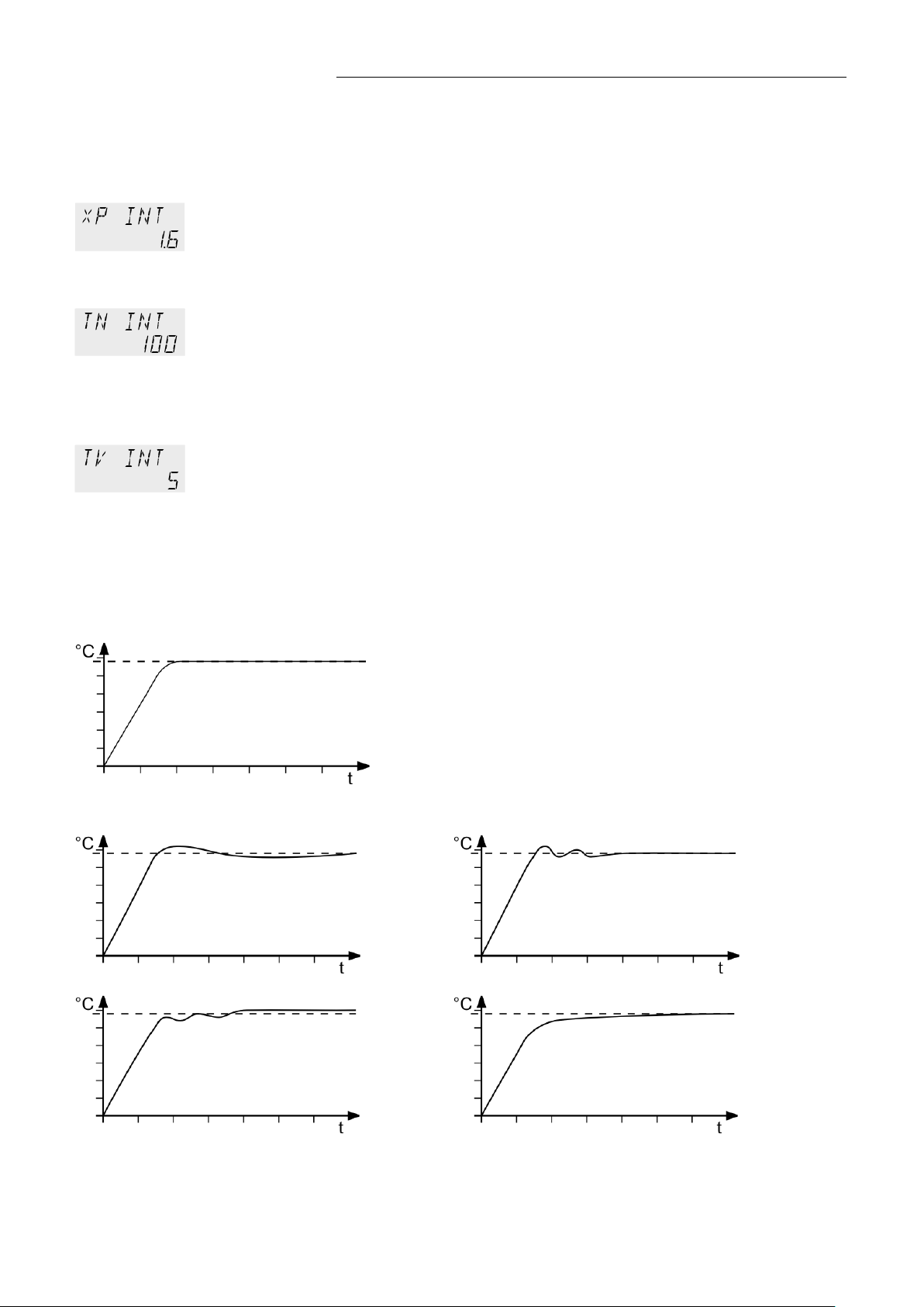
9.5.4. Control parameters– XP-, TN-, TV- INTERNAL
The differential component reduces the transient time. An insufficient lead
Optimum setting
Control parameters XP-, TN-, TV- INTERNAL as well as
Xp too low
Tv/Tn too low
Xp too high or Tv too high
Tv/Tn too high or Xp too high
HE
Setting range: 0.1 ... 99.9
Setting range: 3 ... 9999
Setting range: 0 ... 999
In most cases the control parameters preset in the factory are adequate
for achieving an optimum temp er at ur e s e qu ence.
The cont r ol par ameters allow adj ust m e nt to speci al co ntr ol pr ocesses..
Proportional range >Xp<
The proportional range is the range below the setpoint in which the
control circuit reduces the heating capacity from 100% to 0 %
Reset time >Tn< (Integral component)
Compens a ti o n of t he r em aining control devi ati o n due to pr oportional
regulation. An insufficient reset time may cause instabilities. Excessive
reset times will result in unnecessary prolongation of compensation of the
control difference.
Lead time >Tv< (Differential component)
time will prolong the time required for compensation of disturbance
effects and cause high overshooting during run-up. An excessive lead
time could cause instabilities (oscillations)
Optimization instructions for the PID control parameters
-EXTERNAL
The heat-up curve reveals possible faulty settings of the
control parameter.
Inappropriate settings may produce the following heat-up curves:
47
Page 48

Menu functions
°C
t
Setpoint
5
3
0
Int. temperature
Ext. temperature
Setting range: 0 ... 999
Setting range: 0.1 ... 99.9
The proportional range Xpu of the cascaded controller is only needed for
9.5.5. COSPEED - external
This parameter affects the temperature pattern only in case of external
control.
Possibl e par ameters: 0.0 ... 5.0
During selftuning, the control parameters Xp, Tn and Tv of a controlled
system ar e aut om a t ic al l y determined and stored. Depending on the
controlled system, time for tuning can be unequally longer. This
controller layout allows protection of sensitive objects requiring
temperature applicati on.
As soon as a co-speed factor is set, it is
considered for calculating the control
parameters. As shown in the diagram,
tuning tim es become shorter the hig h er
the co-speed fac t or is, but oversh oo ti ng
can happen in the internal system.
9.5.6. Control parameters – XPU-, XP-, TN-, TV- EXTERNAL
In most cases the control parameters preset in the factors are adequate
for achieving an optimum temp er at ur e s e qu ence.
Setting range: 0.1 ...99.9
Setting range: 3 ... 9999
The contr ol par ameters allow adj ust m e nt to special control processes.
Proportional range >Xpu<
external control.
48
Page 49

Protocol RTS/CTS (Hardware handshake)
9.6. MENU SERIAL - BAUDRATE, HANDSHAKE, PARITY
HE
Menu level 1
For communication between circulator and a PC or a superordinated process
control system the interface parameters of both units must be identical.
For remote control refer to page 72
Level 2 Parameter level
Factory settings:
4800 Baud
even
hardwar e ha ndshake
Press the key if a parameter is to be
retained.
• The param et er flashes, switch by pres s ing
and
• The param et er flashes, switch by pres s ing
even: Data bits = 7; Stop bits = 1
odd: Data bits = 7; Stop bits = 1
no: Data bits = 8; Stop bits = 1
and
• The param et er flashes, switch by pres s ing
Xon/Xoff-protocol (Softwar e ha ndshake)
and
49
Page 50

Menu functions
°C
°C
T 1
T
°C
°C
T 1
T
°C
TT
M
B (INT)
T
°C
TT
M
B (EXT)
T
Pt100
ext
9.7. MENU ATC - Absolut Temper atu re Calibrat ion
ATC serves to compensate a temperature difference that might occur
betwee n cir culator and a defined me as ur i n g point in the bath tank
becaus e o f physi cal proper t ies .
Example:
1-point calibration
For ATC calibration, in steady state the bath temperature at the location
of the temperature sensor (CT) is determined at the respective adjusted
working tem p erature. This value is then set on the circulator in the menu
>ATCalibration< under menu item > CTEMP X <.
This can be a 1-point, 2-point or 3-point calibration.
3-point calibration
Principle:
T
1 = Original curve
T
M = Temperature measuring instrument with temperature sensor
B = Bath tank (INTer nal or E XTer nal)
T = circulator
CT = Temperature on measuring point
TT = Temperature on circulator
50
Page 51

key if parameter is to be retained.
The selected calibration is indicated on level 2 by 1 or
point calibration is carried out, the following menu items are not
Menu level 1
Level 2 Parameter level
or
or
HE
Press the
Correction function for par am eters or values (pri or
to OK).
• The param et er flashes, switch by pres s ing
and
On level 2 a (I) is indicated for internal or an (E)
for external.
Example:
• The param et er flashes, switch by pressing
and
>NO< Carry out an ATC calibration
>YES< retur n to standard operation afte r
calibration.
• The param et er flashes, switch by pres s ing
A >1-point<, >2-point< or >3-point< calibration
can be carried out .
2 or 3.
The value >TMPVAL< is only indicated
In addition the measured temperature value
>CALVAL X< is saved during the next step.
and
• Integer digits flash, set by pressing
+
• Decimal digits flash, set by pressing
+
Level 2 Parameter level
If only a 1-
indicated anymore
The value is only indicated
51
Page 52

Menu functions
point calibration is carried out, the following menu items are not
Level 2 Parameter level
If only a 2-
indicated anymore
• Integer digits flash, set by pressing
+
• Decimal digits flash, set by pressing
+
The value is only indicated
• Integer digits flash, set by pressing
+
• Decimal digits flash, set by pressing
+
9.7.1. ATC SENSOR - INTE RNAL / E XTERNAL
In the first submenu the ATC function is set for the >INTERN< internal or the
>EXTERN< external temperature sensor.
9.7.2. ATC STATUS - YES / NO
Calibration can be carried out for the internal temperature sensor and for the
external temperature sensor connected to the socket „ext. Pt100“.
The circulator is able to save both parameter sets. However only the one
which has b ee n se t und er me nu item > ATC SEN SOR < is displayed.
In the second submenu the ATC function for the temperature sensor selected
above is activated >YES< or deac ti v a te d >NO<.
>YES< (factory setting) The controller of the circulator uses the original
curve of th e tem perature sensor or th e new c urv e m easured during the
ATC calibration.
Important: Set to >NO< during the calibration process
>NO< An ATC calibration is to be carried out.
Important: Set to >YES< after calibration.
In the > ATC STATUS < >YES< the ATC calibration always affects the
current working temperature; also the one set via interface.
52
Page 53
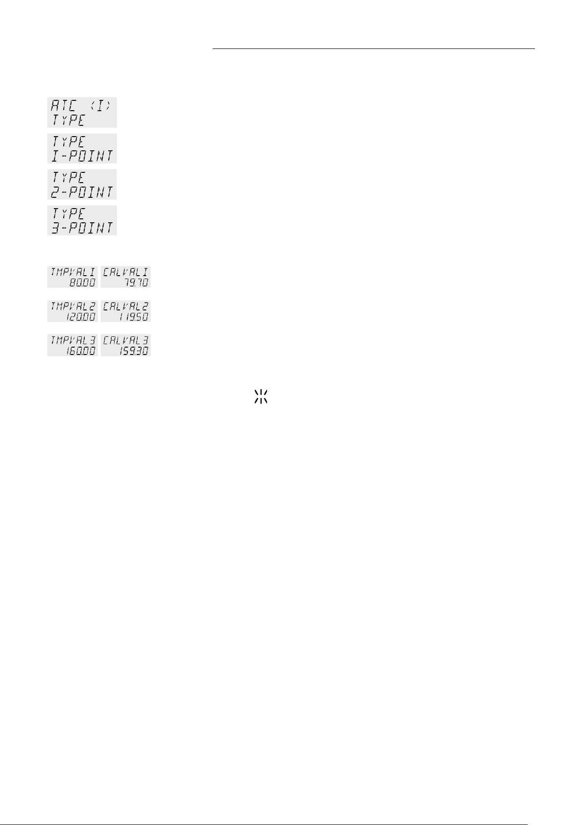
9.7.3. CALIBRATION TYPE: 1 -/ 2 -/ 3 POINT
A >1-point<, >2-point< or >3-point< calibration can be carried out.
HE
First geometrically define the location for calibration (measuring point CT),
then determine the temperature values of the calibration points.
The type of cal i br ations also determines the number of the fol low i n g pai r s o f
values indicated on the LCD DIALOG-DISPLAY.
Pairs o f values:
TMPVAL X: Circulator temperature 1 or 2 or 3 (actual value TT )
The actual temperature of the bath is simultaneously saved with the
“calibration value“ >CALVAL< and can be indicated for control purposes
(value do es no t flash).
CALVAL X: Calibration temperature 1 or 2 or 3 (actual value CT )
The „calibration value“ is determined with a temperature measuring
device and saved under menu item >CALVAL<.
(value flashes
)
53
Page 54

Menu functions
Level 2
Parameter level
and .
9.7.4. Example: 3-point calibration for internal control
In the temperature range from 80 °C to 160 °C the calibration curve of the
temperature sensor (TT) is to be adjusted to the actual temperatures at
measuri ng point (CT).
Menu level 1
80.00 °C
120.00 °C
160.00 °C
1. Set circulator to internal control:
MENU CONTROL page 43
The type of control can be set only in the –OFF- mode.
2. Set working temperature setpoint – SETPNT:
Refer to „Direct temperature setting “ page 27
• By pressing the key
>SETPOINT< see example on the left: >SETPNT / 1 25.00°C<.
The integer di git s flash
• Change the value to 80.00 °C by pressing the keys
confirm by pressing the key
The decim al di gi ts fl as h.
Confirm once more by pressing the key
• The bath is heated up.
Wait for approx. 5 minutes until the temperature is constant.
the circul at or swi tches to the active
(Exampl e: <2 5> ).
and and
.
.
Menu level 1
3. Reading of temperature measuring device
Read the value of measuring point CT on the device and enter under menu
item >CALVAL X< by using the keypa d.
4. Calibration
>CALVAL 1< (79.70 °C)
>CALV AL 2< (119.50 °C)
>CALV AL 3< (159.30 °C)
Press the key if parameter is to be retained. Correction function for
parameters or values (prior to OK).
Setting is required only for the first calibration point.
Set SENSOR IN TER N:
• The param et er flashes, switch by pres si ng
and .
An ATC cali br ati o n i s to be carrie d out.
Set to >NO<
• The param et er flashes, switch by pres si ng
54
Page 55

HE
tion the measured value >CALVAL X< is saved
Return to 2. Set working temperature value SETPNT: 120.00 °C
Return to 2. set working temperature value SETPNT: 160.00 °C
The 3-point calibration is completed
• The param et er flashes, switch by pres si ng
and .
A >3-point< calibration is carried out.
The value >TMPVAL< is only indicated
In addi
during the following step
• Integer digits flash, set by pressing
• Decimal digits flash, set by pressing
(79) +
(70) +
The first of 3 points is calibrated.
The value is only indicated
• Integer digits flash, set by pressing
• Decimal digits flash, set by pressing
The second of 3 points is calibrated.
The value is only indicated.
• Integer digits flash, set by pressing
• Decimal digits flash, set by pressing
5. Return to standard operation
• Set >YES< after calibration.
(Standard operation)
(119) +
(50) +
(159) +
(30) +
55
Page 56

Menu functions
OK).
+
+
In case of external control these menu items are additionally indicated.
+
+
9.8. MENU LIMITS
Menu level 1
Level 2 Parameter level
0 … 100 %
Press the
Correcti o n function for paramet er s or val u es ( pr i or to
• Integer digits flash, set by pressing
• Decimal digits flash, set by pressing
• Integer digits flash, set by pressing
• Decimal digits flash, set by pressing
• The value fl as h es , set by pr es sing
key if parameter is to be retained.
+
+
+
• The value fl as h es , set by pr es sing mit
0 … 100 %
• Integer digits flash, set by pressing
• Decimal di git s fl as h , set by pressing
• Integer digits flash, set by pressing
• Decimal digits flash, set by pressing
• The value fl as h es , set by pr es sing
• The value fl as h es , set by pr es sing
+
+
+
+
+
56
Page 57

The limitation of the operating temperature range effects the temperature
bath fluid.
9.8.1. Limits for internal control
SETPOINT MAX / MIN – Maximum and minimum setpoint
Restriction of the adjustable temperature range.
setting in the menu with the key .
HE
Only setting of working temperatures which lie within the determined
limits is possible
Existing settin gs for SETPNT 1, -2, -3, as well as thos e f or >OVER T MP<
and > SUBTMP < (refer to page 28), are automatically deferred into the
limit range.
Setting range: -94,90 °C ... +300,0 °C
SET MAX > SET MIN
Interchange of values is not possible.
9.8.2. Limits for external control
Set maximum heating / cooling
The heatin g and coolin g capacity of the unit are a dj ustable. 100 %
corresponds to the technical specificatio n o f the equi pment.
Setting range:
HEAT M AX – 0 to 100 % in 1 % steps
COOLING MAX – 0 to 100 % in 1 % steps
> SAFETMP <
INTERN MAX / MIN
Restriction for the temperature range of the internal bath.
Setting range:
The limits INT MAX and INT MIN are only active in external control. INT
MAX and INT MIN determine fixed limits for the temperature within the
internal bath. The temperature controller cannot exceed these limits even
if it would be necessary for achieving the temperature in an external
system. Therefore it is possible that the external setpoint cannot be
achieved.
Sense of limit setting:
-94,9 °C ... +300,0 °C
Protects the bath fluid from overheating.
Prevents an undesired alarm shutdow n by t h e ex c es s t em p er at ur e
protection - >ALARM CODE 14<.
Set the value of > INT MAX at least 5 °C below the value of
>SAFETMP<.
Protects the pump motor from high viscosity of the bath fluid at low
temperatures.
For refrigerated circulat or s . Freezing protection when using water as
57
Page 58
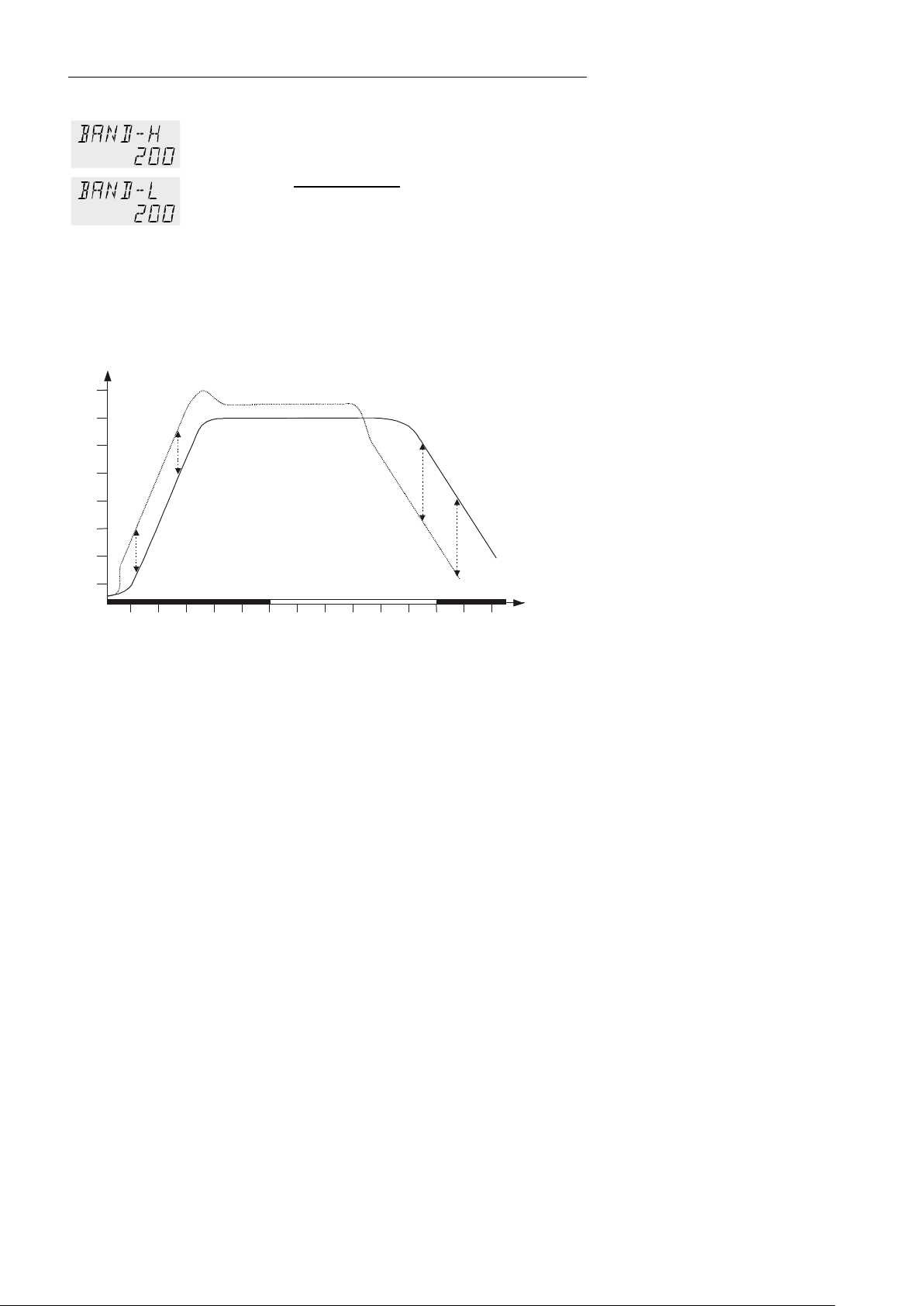
Menu functions
between the temperatures in the internal bath and the external system to
255010203040506010203040506010
[min]
75
100
150
200
°C
t
BAND HIGH
Sense of a band li m i t ati o n:
BAND HIGH / LOW – Band limita tion
The band limitation is active during external control. Varied, practiceoriented setting ar e f easible for heat-up and coo l-down phases.
Setting range: 0 °C ... 200 °C
BAND HIGH and BAND LOW allow for th e lim i tation of the difference
any maximum value for the heat-up and cool-down phase.
During th e hea t-up phase this difference value is always added to the
actual external temperature. During the cool-down phase the difference
value is subtracted.
Internal bath
Protecti o n of objects and samples
by gentle tem p er ature control
external system
Protection of e.g. glass reactors
from thermal shock.
BAND LOW
58
Page 59

9.9. MENU IN/OUT – Analog inputs/outputs (Option)
ALARM
REG+
E-PROG
STAND-BY
Level 2
Level 3
Parameter level
In order to use the analog inputs and outputs, the circulator must be
equipped with the elec tr o ni c m od ul e avai l a bl e as option.
Order No. 8 900 100 Elec tr oni c module
This submenu enables setting of the input and output values for the
programmer input and the temperature recorder outputs of socket REG+E-
Menu level 1
PROG.
The >STAND-BY< input and the >ALARM< output are configurable.
Press the key if parameter is to be retained. Correct ion function for
parameters or values (prior to OK).
HE
• The param et er flashes,
switch by pressing
and
ACTINT [°C]
internal actual temperature value
(bath temperature)
ACTEXT [°C]
external actual temperatur e
value (external sensor)
S-POINT [°C]
active set point temperature
POWER [%]
• Integer digits flash, set by
pressing
+
• Decimal digits flash, set by
pressing
+
• The param et er flashes,
switch by pressing
and
59
Page 60

Menu functions
Level 2
Level 3
Parameter level
• Integer digits flash, set by
pressing
+
• Decimal digits flash, set by
pressing
+
• The param et er flashes,
switch by pressing
and
• Integer digits flash, set by
pressing
+
• Decimal digits flash, set by
pressing
+
• The param et er flashes,
switch by pressing
and
60
• The param et er flashes,
switch by pressing
and
The parameter flashes,
or
switch by pressing
and
Define the indication of
or
VOLTAGE CURRENT
Page 61
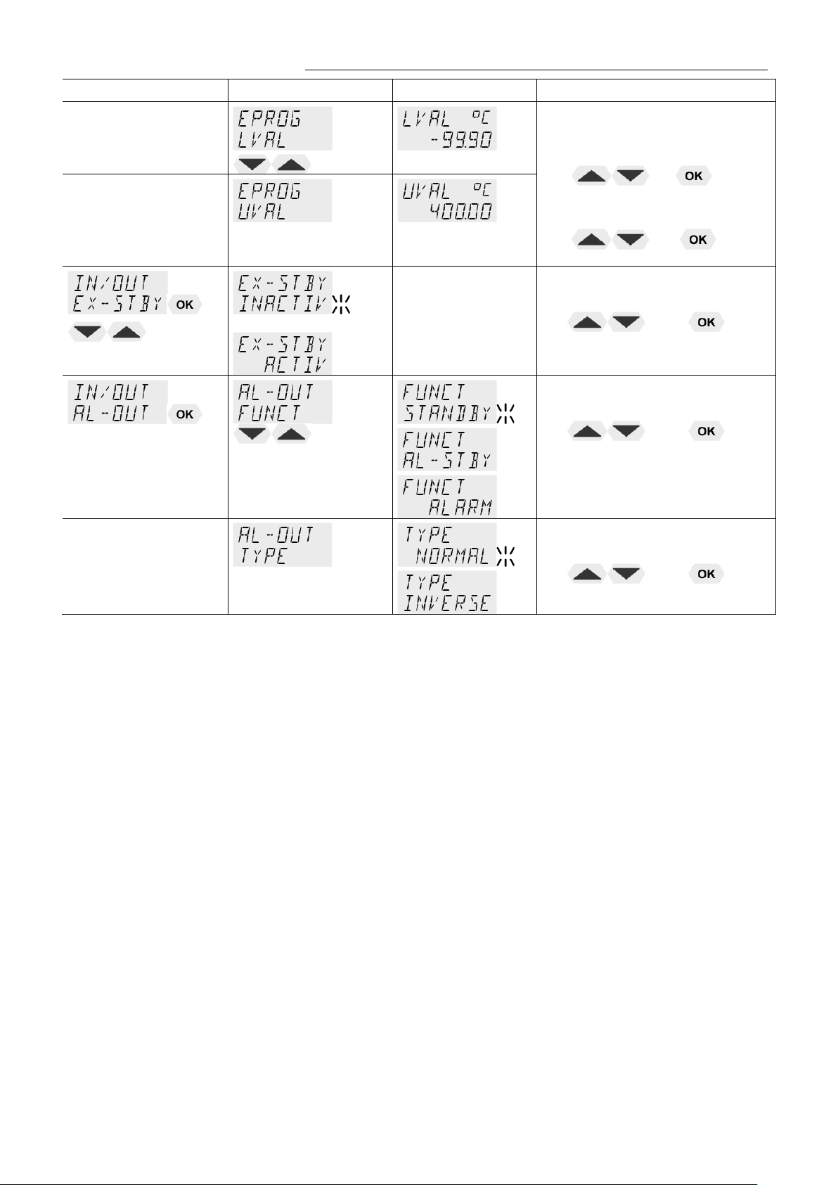
HE
Level 2
Level 3
Parameter level
Lower VALue
or
Upper VALue
• Integer digits flash, set by
pressing
+
• Decimal digits flash, set by
pressing
+
• The param et er flashes,
switch by pressing
and
• The param et er flashes,
switch by pressing
and
• The param et er flashes,
switch by pressing
and
61
Page 62
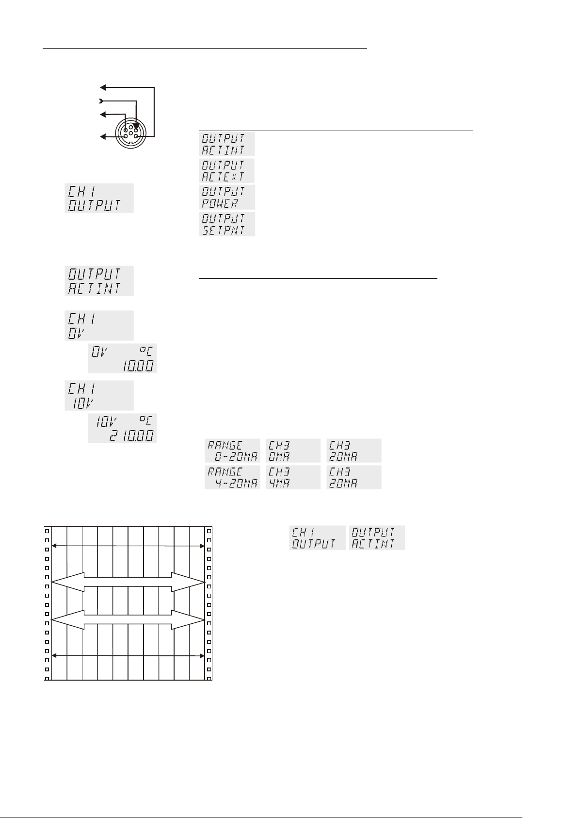
Menu functions
CHANNEL 1
CHANNEL 3
CHANNEL 2
REG+E-PROG
EPROG
Assign the voltage values of 0 V to the lowest and 10 V to the highest
necessary temperature (°C) or power rating (%) required as an output
0 V
0 mA
20 mA
4 mA
10 °C
210 °C
197 °C
202 °C
∆ Τ =
5 K
∆ Τ =
200 K
9.9.1. Outputs of the connector - REG+E-PROG
REG+E-PROG :
1. Selec t CH AN N E L 1, 2 or 3
2. Fir st defi ne the des i r e d out put value for CHANNELs 1 to 3:
1.
2.
3.
internal actual temperature value (bath temperature))
external actual temperature value (external sensor)
periodic or intermittent heating or cooling
active setpoint temperatur e
(SETPoint 1, 2, 3,/ integr. programmer /external programmer)
3. Then select the display size for CHANNELs 1 to 3:
Voltage outputs CHANNELs 1 and 2
value.
CHANNEL 3: Output for temperature value (°C) / power (%)
The current output (channel 3) offers 2 ranges for selection:
0 mA to 20 mA or
4 mA to 20 mA
Assign the current values 0 mA or 4 mA to the lowest and 20 mA to
the highest temperature (°C) or power rating (%) required as an
output value.
or
Example 1:
lowest temperature value: 10 °C
highest temper a tur e value 210 °C
Fig. shows 20 0 °C scaled to paper width
rise: 50 mV/ °C
Example 2:
lowest temp er a t ur e valu e: 197 °C
highest temperature value: 202 °C
Fig. shows 5 °C scaled to paper width
rise: 2000 mV/°C
62
Page 63
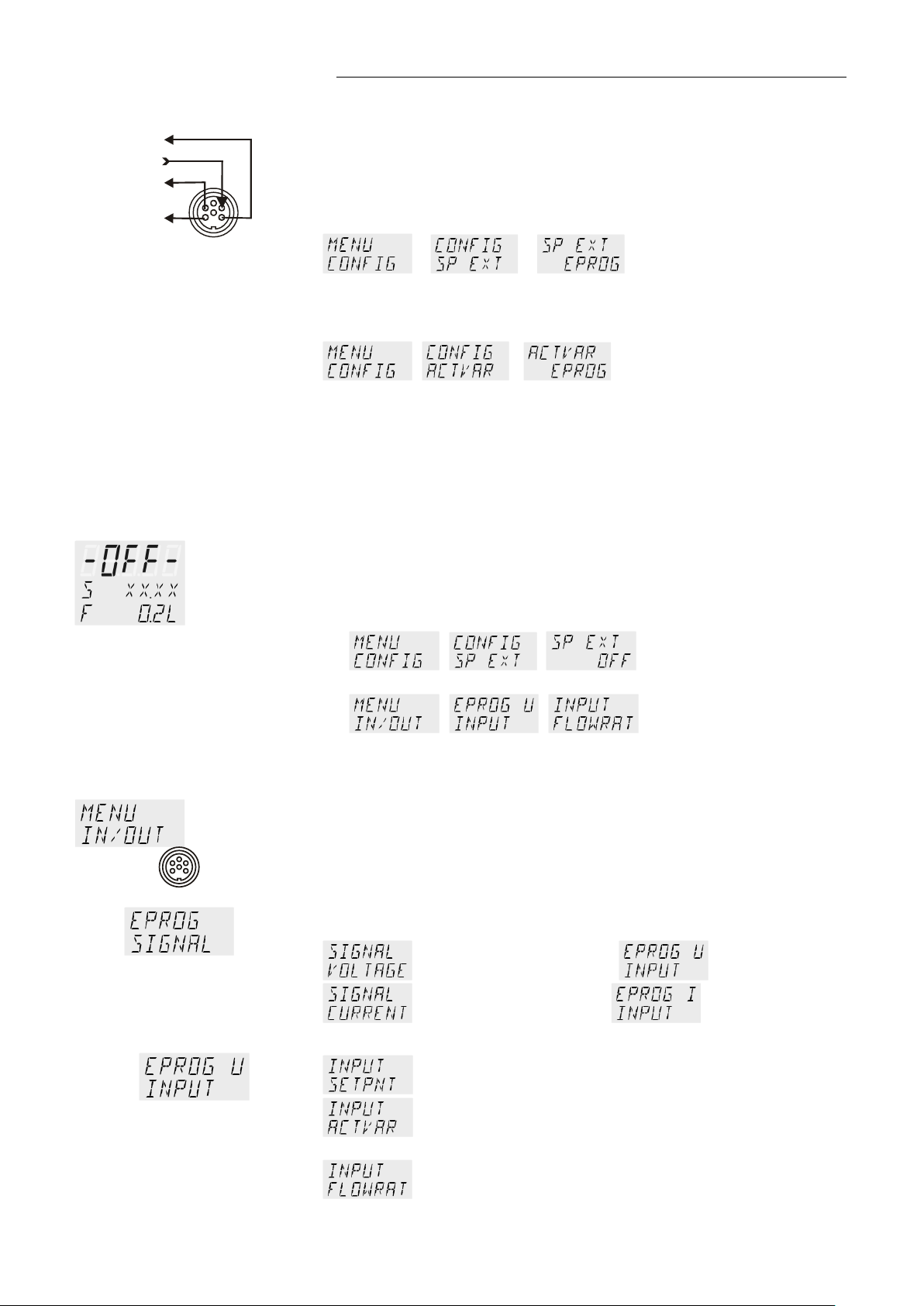
9.9.2. Input of the connector - REG+E-PROG
CHANNEL 1
CHANNEL 3
CHANNEL 2
REG+E-PROG
EPROG
Setting needs to be carried out, if
1. setpoint programming is to be made via an external voltage or
current source or programmer.
For this, in the menu > MENU / CONFIG < first set
the menu item > SETP < to >EPROG<.
HE
>FLOWRAT<
Indicati o n on di s play
> >
2. the heater variable should be controlled via an external control pulse.
For this, in the menu > MENU / CONFIG < set
the menu item >ACTVAR< to >EPROG<.
> > (refer to page 42).
3. the signal of an external flow meter should be registered.
>FLOWRAT< see below.
FLOWRAT
The E-Prog input can only be used either under menu item >CONFIG
-SP EXT< < or under menu item >CONFIG ACTVAR<
If the input is neither occupied by > SP EXT < or > ACTVAR <, the
signal of a flow meter can be connected.
First set >MENU CONFIG<
> >
then >MENU IN/OUT<
Beispiel:
Settings on input - E-PROG
1. Connect the external voltage or current source or programmer to
socket REG+E-PROG of the circulator.
2. Selecting the signal:
The programmer (E-PROG) input of the circulator can be matched to
the ou tput signal of the external voltage or current source.
> >
voltage input = U
current input = I
3. Define the input variable:
with an external c on tr ol pul se
Set point programmed by ext er n al voltage or current
Manipulated (ACTuated) variable for the heater
Signal of an exter nal fl ow sensor
63
Page 64

Menu functions
Examples
20
40
60
80
100
200
300
250
150
°C
1 2 3 4 5 6 7 8 9 10 V
2 4 6810 14 18 20 mA
A
B
Assign a lower temperature threshold value to this adjusted
t value by pressing the appropriate buttons on
:
4. – Setting the LOW value: (See below )
First adjust and set the lowest voltage or current on the external
voltage or current source (e.g. 0 V or 0 mA).
Then after approx. 30 secs enter the corresponding temperature
value (e.g. 20.00 °C).on the circulator by pressing
and
5. – Setting the HIGH value: (See below )
First adjust and set the highest voltage or current on the external
voltage or current source (e.g. 10 V or 20 mA).
Then after approx. 30 secs enter the corresponding temperature
value (e.g. 300 °C).on the circulator by pressing
and
Example:
Set the external voltage or current source output for the equivalent of
50 °C temperature setpoint.
Press
- to standar d di s play.
The temper at ur e v al u e adjusted and set on the external voltage or
current source is displayed in line 2 of the VFD COMFORT-DISPLAY for
control purposes. (Example: SP 50.00 °C).
This EPROG input enables the use of different voltage and current
values as program parameters.
– Setting the LOW value: (See below )
1. Adjust and set the lowest desired value on the voltage or
current sour c e r esp. (Exampl e A: 1 V) .
Wait appr. 30 seconds.
2.
voltage/curren
the keypad of the instrument (Example A: 20 °C ) and set by
pressing
64
1. Adjust and set the highest desired value on the voltage or
current source resp. (Example A: 10 V).
Wait appr. 30 seconds.
2. Assign an upper temperature threshold value to this
adjusted voltage/current value by pressing the appropriate
buttons on the keypad of the instrument (Example A: 200°C)
and set by pressing
Example B in the diagram serves to illustrate that the end
point values are freely selectable (Ex: 8 mA and 16 mA).
.
– Setting the Upper value: (See below )
.
Page 65

HE
Notice:
Important:
(working temperature range see technical specifications)
< pins 2 and 1 ar e connected in any case acc ording
Example out of diagram A:
• Adjusting the voltage source for an output of 7.6 V!
The instrument calculates this value from the rise angle of the two
If this adjustment is not correctly performed at two different points, the setpoint setting
will be incorrect .
predecided end points (in example A: 7.6 V corres po nd to an ex ter n al
setpoint temperature of 152.0 °C ).
After returning the VFD display to standard display, this value is
displayed in line 2 (Example: SP 152.00 °C).
9.9.3. ALARM-output / Stand-by-input
The usable temperature range between > LVAL < and > UVAL < is limited to the
configured working temperature range of the circulator resp. of the unit combination
Alarm output (10)
(for external alarm signal)
Possibl e par ameters:
ALARM
This socket is a potential-free change-over contact. With the adjustments
in the menu item > AL-OUT Function< all operating conditions can be
signaled without having to change the pin assignments.
Signification of the terms under menu item >Function< :
The circulator is in condition >STANDBY< or >ALARM< or >AL-STBY< -
both conditions are signaled.
(STANDBY or ALARM or AL-STBY)
Alarm-TYPE
Possibl e par ameters:
( NORMAL or INVERS )
For >TYPE- NORMAL< pins 2 and 3 are connected in any case
according to the selected > AL-OUT Function<
For >TYPE- INVERS
to the selected > AL-OUT Function<
Switching capacit y max. 30 W / 40 VA
Switching voltage max. 125 V∼/−
Switching current max. 1 A
65
Page 66

Menu functions
1
2
3
AK
AK
1
2
3
STAND-BY
ontact is reclosed. The temperature of the bath fluid changed during
STAND-BY
EX-STBY: External Stand-by input
(for external switch-off)
Possibl e par ameters:
INACTIV - standby input is ignored
ACTIV - standby input is active
Activate the standby input:
1. Under menu item > EXT-STBY <, set the parameter to >ACTIV<.
2. Connect an external contact ‚AK‘ (e.g. for switch-of f) or an alar m
contact of the superordinated system.
In case the connection between Pin 2 and Pin 3 is interrupted by openi ng
the contact ‚AK‘, a complete shutdown of the circ u l ati ng pum p an d heater
is effected, and th e uni t enters the conditi on „E OFF“.
If the contact is reclosed, the instrument returns to the standby state and
„E OFF“ is display ed. Press
Additional tips for using the STANDBY input:
The standby function can be used in conjunction with the AUTOSTART
feature
1. If the Autostart function is NOT turned ON, the standby input is used
as described above.
2. If the Autostart function is enabled, the instrument will revert back to
the original method of entering the setpoint (i.e. keypad, RS232,
Analog input, etc.).
Entering the setpoint with the keypad.
As described above, a bipolar shutdown is accompanied by
displaying the „E OFF“ state. The circulator starts again when the
c
the „E OFF“ state.
Entering the setpoint with the programmer.
The displ ay E OFF appears. The setpoint value and the time are both
held at the current value. The temperature of the bath fluid will be held
constant at this temperature. The programmer continues once the
contact is reclosed.
Notice: This is not an actual shutoff feature.
to start.
e.g.
66
Page 67

+
Repair by authorized JULABO service personnel.
Reconnect the control line or repair short-circuit.
Type of warning: set to >warning< or >alarm< (refer to page 30)
Typ of warning: set to >warning< or >alarm< (refer to page 30)
Cable of working temperature sensor is disconnected or short-circuited.
10. Troubleshooting guide / error messages
Alarm with complete shutdown:
If one of the following failures occur a complete, all-pole shutdown of the
heater and circulating pump is effected.
“ lights up and a continuous signal sounds.
„
The code for the cause of alarm is indicated on the VFD COMFORTDISPLAY.
Alarm without shutdown:
The code for the cause of alarm is indicated on the VFD COMFORTDISPLAY. The warning signal sounds in regular intervals. The messages
appear every 10 seconds.
HE
Press the key
Error message with ticker: >LOW LEVEL ALARM-FILL MEDIUM <
Low level al ar m
The circulator is operated without or insufficient bath fluid.
Switch th e uni t o f f with t h e mains switc h, re fil l ba th flui d an d swi tch on!
Tube breakage has occurred (insufficient filling level of bath fluid caused by
pumping-out)
Replace the tubing and refill bath liquid.
The float is defect (e.g. transport damage).
Error message with ticker:
> REFRIGERATOR ALARM-CHECK CONNECTION <
During th e sel f-test after switch-on a short –circuit is detected between pin 2
and pin 4 of the control line or the control line was disconnected during
operation.
Error message with ticker:
> EXCESS TEMPERAT UR E WARNIN G-CHECK LIMITS <
Excess temperature warning
or
Excess temperature alarm
to stop the signal
Error message with ticker:
> LOW TEMPERATURE WARNING-CHECK LIMITS <
Low temperature warning
or
Low temper ature alarm.
Error message with ticker:
> WORKING SENSOR ALARM-CALL SERVICE <
67
Page 68

Troubleshooting guide / error messages
Other errors
defect.
Error message with ticker:
>SENSOR DIFFERENCE ALARM-CHECK VISCOSITY AND PUMP STAGE<
Defect of working or excess temperature protector.
Working temperature sensor and excess temperature protector report a
temperature difference o f mor e t ha n 35 K.
Error message with ticker:
> INTERNAL HARDWARE ERROR-CALL SERVICE <
Error in A/D converter
Error message with ticker:
> EXCESS TEMPERATURE PROTECTOR ALARM-CHECK ADJUSTMENT <
Excess temperature protector defect.
The protection temperature is below the set worki ng t em p er at ur e s et point.
Set the prot ec ti o n tem perature to a higher v al ue .
Error message with ticker:
> EXTERNAL SENSOR ALARM-CHECK EXTER N AL SEN S OR <
External control was set but the Pt100 external senor was not connected or is
Error message with ticker:
> CLEAN CONDENSER OR CHECK COOLING WATER <
Insufficient cooling of condenser. Clean the air-cooled condenser. Check the
flow and the t em p er at ur e of the coolin g wa ter of a water-cooled condenser.
Error message with ticker:
> COMPRESSOR FAILURE-CHECK REFRIGERATOR <
Stage 1 of the compressors does not work.
Automatic restart after short cool-down, message E 21 goes off.
Stage 2 of the compressor does not work.
Cooling machine – overload prot ec ti o n
The driving motor of the cooling compressor is equipped with an overload
protection which is triggered by increased internal
current consumption.
Shutdown can be caused by
- insufficien t ventilation,
- insufficient wall distance,
- soiled condenser,
- high room temperature
- switching off and on in short sequence
temperatures or excessiv e
68
Excess temperature in stage 1 of the compressor.
Excess temperature in stage 2 of the compressor.
Short circuit of control line to cooling machine during self-test.
Page 69

HE
short-circuited
60
30
1545
4 s
By quickly switching off and restarting the unit the alarm is cancelled.
In this case please call the JULABO Technical Service or an authorized dealer.
Warning:
Only use fin e f uses with a nomin al value as specified.
Manufacturer
Supplier
Type
Order No.
Schurter
Schurter
G-fuse insert SPT
T16A 5x20mm
No. 0001.2516
Wickmann
Wickmann
G- fuse insert
T10,0A 5x20 mm
No. 19195
Error message with ticker:
> SAFETY SEN SOR AL ARM-CALL SERVICE <
The cable of the excess temperature protector has been disconnected or
Ext. Pt100 sensor input without signal, but setpoint programming set to
external Pt1 00.
Error message with ticker:
> LOW LEVEL WARNING-FILL MEDIU M <
The early warning system for low level reports a critical fluid level. Refill bath
fluid.
If the error occurs once more after the restart, a remote diagnosis is required.
Error message with ticker:
> CONFIGURATION ERROR-PRESS OK<
The configuration of the circulator does not correspond with its current
application.
Press the
key for a non-recurring, automatic change of the
configuration.
Disturbances that are not indicated.
The electr oni c pump motor is over load-protect ed by an el ec tronic current
limiter. If viscosity of the bath fluid is or becomes too high, the motor stops
running.
Before exchanging the fuses, turn off the mains power switch and disconnect the
power plug from the mains socket!
Fuses:
The mains fuses on the rear of the unit may easily be exchanged as
shown on the left.
Circulator: Fine fuses T 16 A , dia.5 x 20 mm
Cooling machine: Fuse T 10.0 A, dia.5 x 20 mm
Example:
69
Page 70

Electrical connections
cellular ph on es ) .
4
1
3
2
1
4
2
3
Shield Plug
Look on
soldering side.
Pt100
remote co ntr ol o f th e cir culator.
9 6
5
1
RS232 interface cable
8 980 073
RS232 interface cable 9-pol./9-pol. , 2,5 m
8 900 110
USB interface adapter cable
11. Electrical connections
Notice:
Use shielded cables only.
The shield of the connecting cable is electrically connected to the plug housing.
The unit ensures safe operation if connecting cables with a maximum length of 3 m
are used. The use of longer cables does not affect proper performance of the unit,
however external interfere nc es may hav e a negative impact on sa fe operation (e.g.
Socket for external Pt100 sensor
Pin assig nm en t :
ext. Pt100
Pin Signal
1 I+
2 U+
3 U 4 I-
The shield of the connecting cable is electrically connected to the plug
housing and the sensor tube.
RS232C
Accessories:
RS232 serial interface
This port can be used to connect a computer with an RS232 cable for
Pin assignments R S23 2:
Pin 2 RxD Receive Data
Pin 3 TxD Transmit Data
Pin 5 0 V Sig na l GND
Pin 7 RTS Request to send
Pin 8 CTS Clear to send
Pin 1; 4; 6, 9 Reserved - do not use!
Circulator (9-pol) PC (9-pol)
Pin 2 RxD ⇔ Pin 3 TxD
Pin 3 TxD ⇔ Pin 2 RxD
Pin 5 GND ⇔ Pin 5 GND
Pin 7 RTS ⇔ Pin 8 CTS
Pin 8 CTS ⇔ Pin 7 RTS
Order No. Description
70
Page 71

HE
AK
1
2
3
STAND-BY
3
4
6
/ Control output
The connector may only be used for control of a JULABO refrigerated
circulator or JULABO MVS Solenoid valve controller for cooling water.
Pin assig nm en t :
Pin Signal (only with attached JULABO equipment)
1 +24 V (I max. current 25 mA)
2 0 V
3 Alarm relay
4 Reserved - do not use!
5 Cooling pu ls e
Alarm output
(for external alarm signal)
This potential-free change-over contact is activated in case of an alarm
when pins 2 and 3 are connected.
Switching capacit y max. 30 W / 40 VA
Switching voltage max. 125 V∼/−
Switching current max. 1 A
ALARM
Functional description see page 65
STAND-BY input
(for external emergency switch-off)
Pin assig nm en t : Pin Signal
1 not connected
2 5 V / DC
3 0 V
Functional description see page 6
Programmer input / temperature recorder output
2
Pin Signal
1
REG+E-PROG
5
1 Voltage output Channel 1 0 ... 10 V
2 Voltage output Channel 2 0 ... 10 V
3 GND for outputs 0 V
4 Programmer input EPROG 0 to 10 V / 0 to 20 mA
5 Current output Channel 3 0 to 20 mA / 4 to 20 mA
6 GND for Progammer 0 V
Functional description see page 62
71
Page 72

Remote control
9 6
5
1
3. Connect both units with an interface cable..
Like all parameters which can be entered through the keypad, interface
parameters are stored in memory even after the circulator is turned off.
If the circulator is put into remote control mode via the configuration level, the
In general, the computer (master) sends commands to the circulator (slave).
In remote control mode, the start command and all values to be set must be
A transfer sequence consists of:
To ensure a safe data transfer, the time gap between two commands should
The out commands are valid only in remote control mode.
Response from the circulator: 55.5↵
12. Rem ot e control
12.1. Setup for remote control
1. Check the inter face parameters for bot h int erfaces (on circulator and PC)
and make sure they match.
RS232C
(Serial int erface re fer to pa ge 49)
2. In the menu > MENU CONFIG < set
the menu item
12.2. Communication with a PC or a superordinated data system
VFD COMFORT-DISPLAY will read “R -OFF-” = REMOTE STOP. The
circulator is now operated via the computer.
The circulator sends data (including error messages) only when the
computer sends a query.
resent by the PC via the interface in case of a power interruption.
AUTOSTART is not possib le.
to
.
• command
• space (
; Hex: 20)
⇔
• parameter (decimal separation with a period)
• end of file (↵; Hex: 0D)
The comma nds ar e di vi d ed into in and out commands.
in commands: retrieve parameters
out commands: set parameter s
Important times for a command transmission:
be at least 250 ms.
The circulator automatically responds to an in comm and wit h a data string
followed by a LF (Line Feed). The next comman d s ho ul d onl y be se nt a ft er
10 ms.
Command to set the working temperature > SETPNT 1< to 55.5 °C
out_sp_00 ⇔ 55.5↵
Command to retrieve the working temperature > SETPNT 1< in_sp_00↵
72
Page 73

Temperature control by using the stored parameters.
Single selftuning of controlled system after the next start.
setpoint is to be reached.
Voltage 0 V ... 10 V
Current 0 mA ... 20 mA
-99.99 ... +1 00 [ %]
12.3. List of commands
out commands: Setting temperature values or parameters.
Command Parameter Response of circulator
out_mode_01 0 Use working temperature > SETPNT 1<
out_mode_01 1 Use working temperature > SETPNT 2<
out_mode_01 2 Use working temperature > SETPNT 3<
out_mode_02 0 Selftuning „off“.
out_mode_02 1 Selftuning „once“
out_mode_02 2 Selftuning „always“
Continual selftuning of controlled system whenever a new
out_mode_03 0 Set external programmer input to voltage.
HE
out_mode_03 1 Set extern al pro gr am m er input to current.
out_mode_04 0 Temperature control of internal bath.
out_mode_04 1 External control with Pt100 sensor.
out_mode_05 0 Stop the unit = R –OFF-.
out_mode_05 1 Start the unit.
out_mode_08 0 Set the contr ol dynamics - aperiodic
out_mode_08 1 Set the control dynamics - standard
out_sp_00 xxx.xx Set working temperature. „SETPNT 1“
out_sp_01 xxx.xx Set working temperature. „SETPNT 2“
out_sp_02 xxx.xx Set working temperature. „SETPNT 3“
out_sp_03 xxx.xx Set high temperature warning limit „OverTemp“
out_sp_04 xxx.xx Set low temperature warning limit „SubTemp“
out_sp_06 xxx.xx Set manipulated variable for the heater via serial interface
out_sp_07 x Set the pump pre s sur e st age. (1 ... 4)
out_par_04 x.x CoSpeed for external control 0 ... 5.0
out_par_06 xxx Xp control parameter of the internal controller. 0.1 ... 99.9
out_par_07 xxx Tn control parameter of the internal controller. 3 ... 9999
out_par_08 xxx Tv control param eter of the internal controller. 0 ... 999
out_par_09 xxx Xp control parameter of the cascade controller. 0.1 ... 99.9
out_par_10 xxx Proportional por tion of the cascade co ntr ol ler . 1 ... 99.9
out_par_11 xxx Tn control parameter of the cascade controller. 3 ... 9999
73
Page 74

Remote control
This adjustment only makes sense if FP refrigerating units are
used.
(REG+E-PROG) .
after start.
sensor
Command Parameter Response of circulator
out_par_12 xxx Tv control parameter of the cascade controller. 0 ... 999
out_par_13 xxx Maximum internal temperature of the cascade controller.
out_par_14 xxx Minimum internal temperature of the cascade controller.
out_par_15 xxx Band limit (upper) 0 ... 200 °C
out_par_16 xxx Band limit (lower) 0 ... 200 °C
out_hil_00 -xxx Set the desire d maxi mum cooling power (0 % to 1 00 %) .
Note: Enter the value with a preceding negative sign!
out_hil_01 xxx Set the desired maximum heating power (10 % to 100 %).
in commands: Asking for parameters or temperature values to be displayed.
Command Parameter Response of circulator
version none Number of software version (V X.xx)
status none Status message, error message (see page 76)
in_pv_00 none Actual bath temperature.
in_pv_01 none Heating power being used (%).
in_pv_02 none Temperature value registered by the external Pt100 sensor.
in_pv_03 none Temperature value registered by the safety sensor.
in_pv_04 none Setpoint temperature of the excess temperature protection
in_sp_00 none W orking temperature „SETP 1“
in_sp_01 none W orking temperature „SETP 2“
in_sp_02 none W orking temperature „SETP 3“
in_sp_03 none High temperature warning limit „OverTemp“
in_sp_04 none Low temperature warning limit „SubTemp“
in_sp_05 none Setpoint temp er ature of the external pr ogrammer
in_sp_07 none 1. Adjusted pump stage in the -OFF- condition.
2. Pump stage corresponding to the effective rotation speed
in_sp_08 none Value of a flowrate sensor co nnected to the E-Prog input
in_par_00 none Temperature difference between working sensor and safety
in_par_01 none Te - Ti m e constant of the exter nal bat h.
in_par_02 none Si - Internal slope
in_par_03 none Ti - Time constant of the internal bath.
74
Page 75

Command Parameter Response of circulator
temperatures in the internal bath and external system).
Ratio of max. cooling capacity versus max. heating capacity
controller.
controller.
thr ou gh an ex ternal programmer
2 = Selftuning „alwayS“
1 = Current 0 mA to 20 mA
1 = Temperature control with external Pt100 sensor.
1 = Start
1 = standard
in_par_04 none CoSpeed - Band limit (max. difference between the
in_par_05 none F act or pk/ph0:
in_par_06 none Xp control parameter of the internal controller.
in_par_07 none Tn control parameter of the internal controller.
in_par_08 none T v con tr ol par ameter of the internal controller.
in_par_09 none Xp control parameter of the cascade controller.
in_par_10 none Pr oportional porti on o f th e cas cade controller.
in_par_11 none Tn control parameter of the cascade controller.
in_par_12 none T v con tr ol par ameter of the cascade controller.
in_par_13 none Adjusted maximum internal temperature of the cascade
in_par_14 none Adjusted minimum internal temperature of the cascade
in_par_15 none Band limit (upper)
HE
in_par_16 none Band limit (lower)
in_mode_01 none Selected setpoint:
0 = SETP 1
1 = SETP 2
2 = SETP 3
3 = Last setpoint setting was carried out
in_mode_02 none Selftuning typ e:
0 = Selftuning „off“
1 = Selftuning „once“
in_mode_03 none Type of the external pr o gr am m er in pu t:
0 = Voltage 0 V to 10 V
in_mode_04 none Internal/external temperature control:
0 = Temperature control with internal sensor.
in_mode_05 none Circulator in Stop/Start condition:
0 = Stop
in_mode_08 none Adjusted control dynamics
0 = aperiodic
in_hil_00 none Max. cooling power (%).
in_hil_01 none Max. heating power (%).
75
Page 76

Remote control
00 MANUAL S TOP
Circulator in „OFF“ state.
01 MANUAL START
Circulator in keypad control mode.
02 REMO TE ST OP
Circulator in „r OFF“ state.
03 REMO TE ST ART
Circulator in remote control mode.
Value lies outside the adjusted range for the high and low
12.4. Status messages
Status messages
12.5. Error me ss a ges
Error messages
-01 LOW LEVEL ALARM
-02 REFRIGERATOR ALARM
-03 EXCESS TEMPERATU R E
WARNING
-04 LOW TEMPERATUR E WARNING
-05 WOR KING SENSO R ALARM
-06 SENSOR DIFFERENCE ALARM
-07 I2C-BUS ERROR
Description
Description
Low liquid level alarm.
Control cable of the refrigerated circulator or MVS
solenoid valve controller short-circuited or int er r up ted.
High temperature warning.
Low temperature warning.
Working temperature sensor short-circuited or interrupted.
Sensor differenc e al ar m .
Working temperature and safety sensors report a
temperat ur e difference of more tha n 35 K.
2
Internal error when reading or writing the I
C bus.
-08 INVALID COMMAND
-09 COMMAND NOT ALLOWED IN
CURRENT OPERATING MODE
-10 VALUE TOO SMALL
-11 VALU E TOO LARGE
-12 TEMPERATURE MEAS UREMENT
ALARM
-13 WARNING : VALUE EXCEEDS
TEMPERATURE LIMITS
-14 EXCESS TEMPERATU R E
PRO T E CTO R AL AR M
-15 EXTERNAL SENSOR ALARM
-20 WARNING: CLEAN CONDENSOR
OR CHECK COOLING WATER
CIRCUIT OF REFRIGERATOR
-21 WARNING: COMPRESSOR STAGE
1 DOES NOT WORK
Invalid command.
Invalid command in current operating mode.
Entered value too small.
Entered value too large.
Error in A/D converter.
temperature warning limits . But value is stored.
Excess temperature protector alarm
External control selected, but external Pt100 sensor not
connected.
Cooling of the condenser is affected.
Clean air-cooled condenser.
Check the flow rate and cooling water temperature on
water-cooled condenser.
Compressor stage 1 does not work.
-22 WARNING: COMPRESSOR STAGE
2 DOES NOT WORK
76
Compressor stage 2 does not work.
Page 77
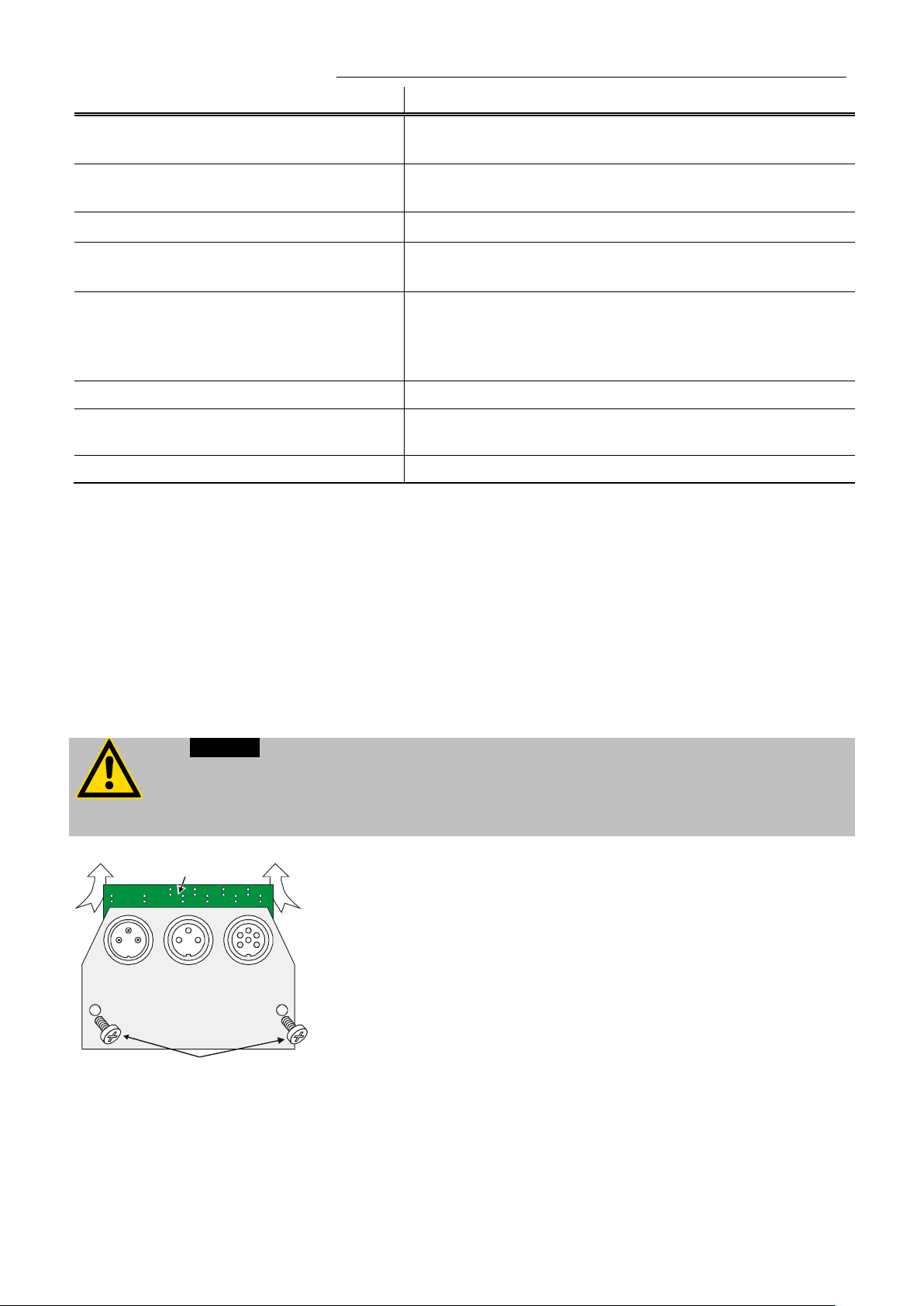
HE
to automatically perform a single modification
Caution:
carried out by quali fie d per sonnel.
ALARM
REG+
E-PROG
STAND-BY
A
B
Error messages
-23 WARNING: HI GH TEMPERATURE
ON COMPRESSOR STAGE 1
-24 WARNING: HI GH TEMPERATURE
ON COMPRESSOR STAGE 2
-25 REFRIGERATOR WARNING
-26 WARNING: S TAND -BY PLUG IS
MISSING
-30 CONFIGURATION ER ROR:
CONFIRM BY PRESSING <OK> ON
CIRCULATOR
-33 SAFETY SENSOR ALARM
-38 EXTERNAL SENSOR SETPOINT
PRO GRAM MING ALAR M
-40 NIVEAU LEVEL WARNUNG
Description
Excess temperature on compressor stage 1.
Excess temperature on compressor stage 2.
Error in the cooling machine.
External standby contact is open.
(see page 65 and 71)
The configuration of the circulator does not conform to its
present use.
Press >OK<
of the configuration.
Excess temperature sensor short-circuited or interrupted.
Ext. Pt100 sensor input without signal and setpoint
program m i ng set to external Pt100.
Low liquid level warning in the internal reservoir.
13. Ins tal l at i o n of electr oni c m od ul e
Always tur n o ff the uni t and di s c onnect the mains cable from th e pow er s our ce before
performing any service or maintenance procedures, or before moving the unit.
Configuration, installation, maintenance and repairs on the circulator may only be
• Turn off the unit with the mains switch and disconnect the
power plu g.
• Open the screws (A) and remove the dummy plate.
• Carefully insert the upper edge (B) into the rear panel from
below, align the electronic module at top and bottom and
applying light pressure connect the 15-pole connector.
• Attach the electronic module using the screws (A).
• The circulator is ready for use. It automaticall y recognizes the
installe d el ec tronic module.
77
Page 78
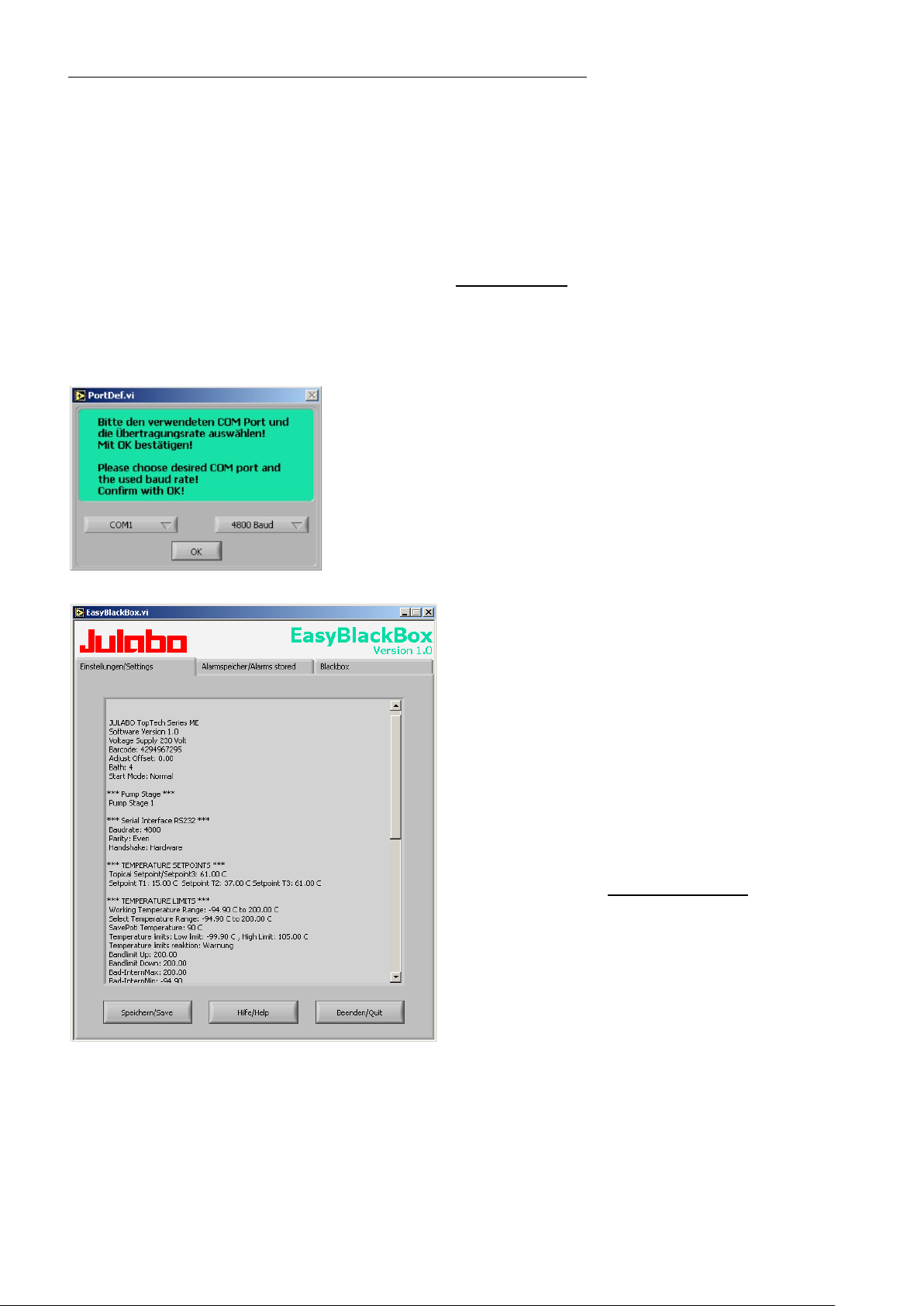
JULABO Service – Online remote diagnosis
The program asks for the port used (COM1, ......) and the baud
settings ar e made.
14. JULABO Service – Online remote diagnosis
JULABO circulators of the HighTech series are equipped with a
black box. This box is implemented in the controller and records
all significant data for the last 30 minutes.
In case of a failure, this data can be read out from the unit by
using special software. This software is available as a free
downloa d fr om
• Installation is easy and is performed step by step.
Please observe the instructions.
• Data read-out is possible in the conditions
“OFF”, “R OFF” or “ALARM”.
• Connect the circulator to the computer using an interface
cable.
• Start the EasyBlac k B ox pr o gr am .
rate of the uni t.
You do not have this information on hand? Simply try it out!
The program continues to send the request until the correct
www.julabo.de \ EasyBlackBox.
• Data is read out and shown on the monitor
divided into the sections
>Einstellungen/Settings<,
>Alarmspei c her/Alarms stored<,
>Blackbox<
see example
• After press ing >Speichern/ S ave<, a text file is
created. Th e pr ogram suggests a filename >C:\model descr iption and barcode no.<.
Modifications are possible.
• E-mail this file to
service department. JULABO is thus able to
provide rapid support.
service@julabo.de, JULABO's
78
Page 79
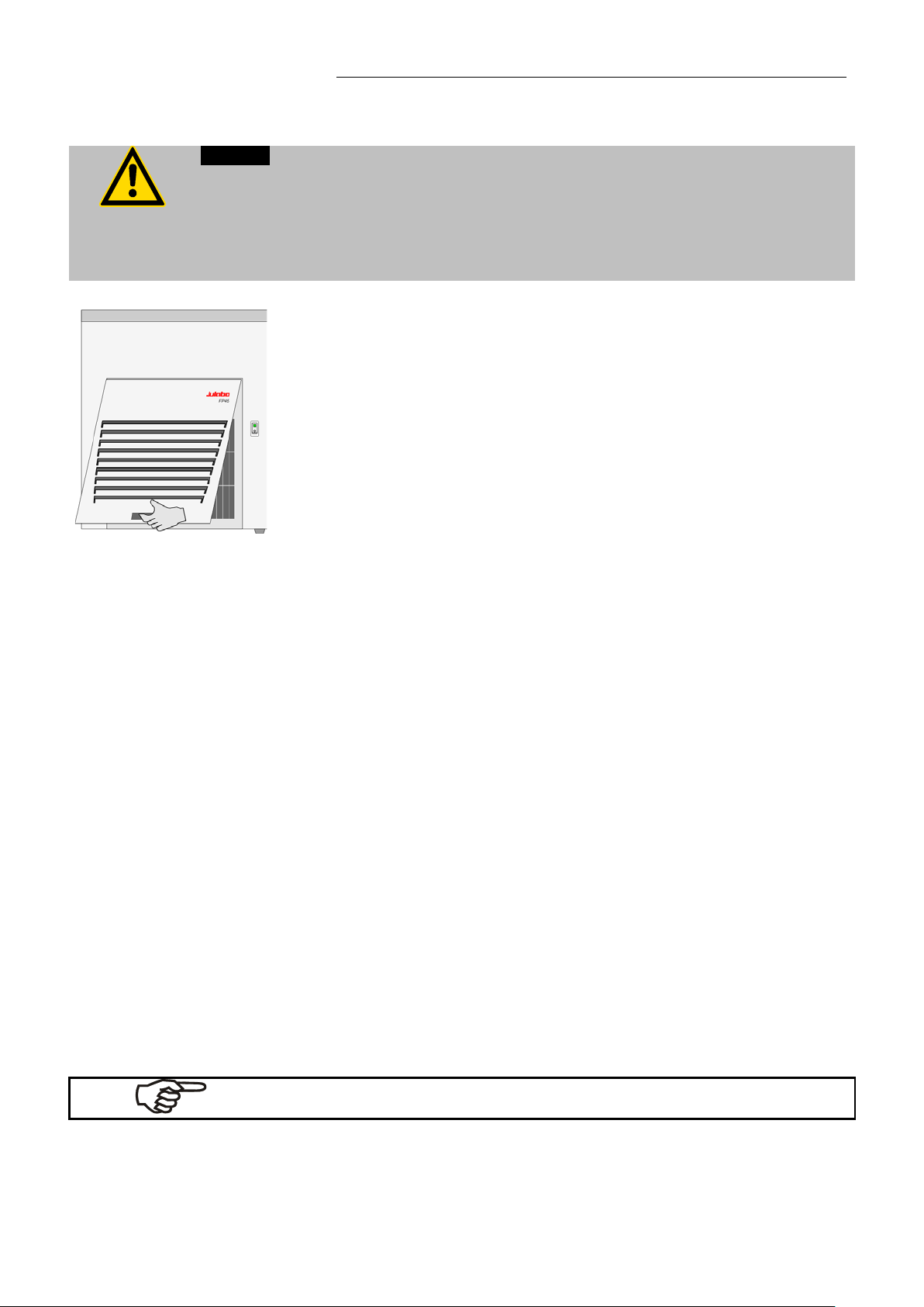
Caution:
personn el onl y.
To maintain the full cooling performance, clean the condenser from time to
To avoid contamination, it is essential to change the bath fluid from time to
time.
insufficient packing.
JULABO reserves the right to carry out technical modifications with repairs
for providing improved performance of a unit.
15. Cleaning / repairing the unit
• Always turn off the unit and disconnect the mains cable from the power source
before cleaning the unit.
• Prevent humidity from entering into the circulator.
• Electrical connections and any other work must be performed by qualified
time.
• Switch o ff th e unit, discon nect mains pow er cable.
• Hold the venting grid, pull out and remove.
• Clean the ribbed condenser with a vacuum cleaner.
• Replace the venting grid.
• Switch on the unit.
HE
Cleaning:
For cleaning the bath tank and the immersed parts of the circulator, use
low surface tension water (e.g., soap suds).
Clean the outside of the unit using a wet cloth and low surface tension
water.
The circulator is designed for continuous operation under normal
conditions. Periodic maintenance is not required.
The tank sho ul d be f il l ed o nl y with a bath fluid rec om m en ded by JULAB O.
Repairs
Before asking for a service technician or returning a JULABO
instru ment for repair, please contact an authorized JULABO service
station.
When returning the un it:
• Clean the uni t i n or der to avoid any harm to the se r vi c e per son nel.
• Attach a shor t fa ult desc r i p tion.
• During transport the unit has to stand upright. Mark the packing
correspondingly.
• When returning a unit, take care of careful and adequate packing.
• JULABO is not responsible for damages that might occur from
79
 Loading...